Embed Size (px)
Citation preview

1 FORM NO. L-20283-F-0704
Elgin Hydraulic Clutch-BrakeECB-240, Product Number 964225
FORM NO. L-20283-F-0704

2FORM NO. L-20283-F-0704
In accordance with Nexen’s established policy of constant product improvement, the specifications contained in thismanual are subject to change without notice. Technical data listed in this manual are based on the latest informationavailable at the time of printing and are also subject to change without notice.
Technical Support: 800-843-7445(651) 484-5900
www.nexengroup.com
Copyright 2004 Nexen Group, Inc.
Nexen Group, Inc.560 Oak Grove Parkway
Vadnais Heights, Minnesota 55127
ISO 9001 Certified
Read this manual carefully before installation and operation.
Follow Nexen's instructions and integrate this unit into your system with care.
This unit should be installed, operated and maintained by qualified personnel ONLY.
Improper installation can damage your system or cause injury or death.
Comply with all applicable codes.
DANGER

3 FORM NO. L-20283-F-0704
Table of Contents
INSTALLATION ----------------------------------------------------------------------------------------------------------------- 4
INSTALLATION OF CHECK VALVE -------------------------------------------------------------------------------------- 5
TROUBLESHOOTING ------------------------------------------------------------------------------------------------------- 6
PARTS REPLACEMENT ---------------------------------------------------------------------------------------------------- 7
REPLACEMENT PARTS -------------------------------------------------------------------------------------------------- 10
PARTS LIST ------------------------------------------------------------------------------------------------------------------- 11
WARRANTY ------------------------------------------------------------------------------------------------------------------- 12

4FORM NO. L-20283-F-0704
INSTALLATION
FIGURE 1
NOTE: Mount the Hydraulic Clutch/Brake with the Plugfacing up and the hydraulic inlet port facing down.
1. Apply a thin film of Never Seez® to the splined end of theDrive Disc (See Figure 1).
2. Using customer supplied socket head cap screws, securethe Hydraulic Clutch/Brake to the transmission gear box.
NOTE: The driveline must be offset 3o to 5o to ensure properlubrication of the driveline knuckles.
3. Attach the customer supplied driveline to the SAE flangedadapter.
4. Attach a customer supplied #6 or greater hydraulic pressureline to the hydraulic port of the Hydraulic Clutch/Brake (SeeFigure 1).
NOTE: The Hydraulic Clutch/Brake is rated for 270 to 280psi [19.3 bar] with a recommended operating pressure of280 psi [19.3 bar].
5. Remove the Plug (located in a vertical position on aproperly mounted Hydraul ic Clutch/Brake) (SeeFigure 1).
6. Turn the engine over until the hydraulic oil flows from thetop port, bleeding the air from the Hydraulic Clutch Brake.Turning the engine over will activate the hydrostatic chargepump which also powers the Hydraulic Clutch/Brake.
7. Tighten the Plug after the air is bled from the HydraulicClutch/Brake.
Apply a thin film of Never Seez® tothe splined end of the Drive Disc.
Hydraulic Bleed PortNexen
SuppliedPlug
Customer SuppliedHydraulic Line
DANGERNever use your hand to check the condition of hydraulic lines. If hydraulic fluid
penetrates the skin, get medical help immediately. Failure to get proper medical helpmay result in loss of limb or life. The safest way to check hydraulic lines for leaks is by
holding a piece of cardboard next to the hydraulic line.

5 FORM NO. L-20283-F-0704
INSTALLATION OF CHECK VALVE
The PTO drive system in a Pelican S is engaged by a hydraulically operated clutch. A spring applied friction brake is alsoincorporated in the clutch assembly to prevent the rotation of the brooms while the clutch is disengaged. Hydraulic pressuresupplied by the hydrostatic-drive-charge-pump circuit is used to engage the clutch.
Pelican S model sweepers S8500 and higher use hydrostatic charge pressure regulated to 270 to 280 psi to engage the broomclutch. During operation, charge pressure can drop significantly for a short time. A Check Valve is used to prevent stalling duringnormal fluctuations of charge pressure. Pressure test ports are included on both the pressure regulating valve and the clutchhousing. These ports can be used to check engagement and disengagement pressures when performing diagnostics on clutchproblems.
Install Check Valve referencing the diagram below.
G
C
T
P
Clutch pressure testClutch valve test port
Install Check Valve 1076694 (part of kit)
Install Elbow 1042222 (part of kit)
PELICAN S CLUTCH CIRCUIT

6FORM NO. L-20283-F-0704
TROUBLESHOOTING
Bearings
Bearings
O-ring SealsClutch Disc
Cylinder Housing
SAEFlanged
Shaft
Brake Housing
FIGURE 2
SAE #6Hydraulic
Port
Return Springs
BearingHousing
Input Spline
Drive Disc
Housing
ClutchFriction Facing
Hydraulic Seals
Piston
BrakeFriction Facing
SYMPTOM PROBABLE CAUSE SOLUTION
HydraulicClutch/Brake slips
Low hydraulic pressure. Check hydraulic pump pressure or system for leaks ormalfunctioning charge pump and replace pump if necessary.
Restricted hydraulic line or hydraulicline too small for application.
Check hydraulic line for restrictions or replace hydraulic line (#6 lineminimum).
Worn O-ring or Hydraulic Seals. Replace O-ring and Hydraulic Seals.
Wrong viscosity hydraulic fluid forambient temperature conditions.
Replace hydraulic fluid with correct viscosity hydraulic fluid forambient temperature conditions.
Dirty or contaminated Facings. Replace Friction Facings.
HydraulicClutch/Brake fails
to engage
Worn O-ring or Hydraulic Seals. Replace O-ring and Hydraulic Seals.
Restricted hydraulic line or hydraulicline too small for application.
Check hydraulic line for restrictions or replace hydraulic line (#6 lineminimum).
Low hydraulic pressure. Check hydraulic pump pressure or system for leaks ormalfunctioning charge pump and replace pump if necessary.
Faulty hydraulic control system. Replace hydraulic control system and replace system if necessary.
HydraulicClutch/Brake fails
to disengage
Oil from Hydraulic Clutch/Brakechamber does not drain to tank.
Check hydraulic circuit for a faulty control valve and replace valve ifnecessary.
Restricted hydraulic line or hydraulicline too small for application.
Check hydraulic line for restrictions or replace hydraulic line (#6 lineminimum).
Faulty hydraulic control. Replace hydraulic control system.
Wrong viscosity hydraulic fluid forambient temperature conditions.
Replace hydraulic fluid with correct viscosity hydraulic fluid forambient temperature conditions.

7 FORM NO. L-20283-F-0704
PARTS REPLACEMENT
HOUSING
1. Remove the twelve Socket Head Cap Screws (Item 21)and Flat Washers (Item 27); then, remove the Housing(Item 1) (See Figure 3).
WARNINGSpecial attention should be exercised when
working with retaining rings. Always wear safetygoggles when working with spring or tension
loaded fasteners or devices.
2. Remove the Retaining Ring (Item 13); then, press the DriveDisc (Item 2) and Bearing (Item 15) out of the Housing(Item 1) (See Figure 4).
3. Remove the Retaining Ring (Item 17) (See Figure 4).
4. Press the old Bearing (Item 12) out of the Housing (Item 1)(See Figure 4).
5. Remove the Retaining Ring (Item 16) from the Drive Disc(Item 2) (See Figure 4).
6. Using a bearing puller, remove the old Bearing (Item 15)from the Drive Disc (Item 2) (See Figure 4).
7. Clean both bearing bores of the Housing (Item 1) withfresh safety solvent, making sure all old Loctite® residuehas been removed.
WARNINGDo not touch heated parts with bare hands. Useinsulated gloves or tongs to handle heated parts.
8. Supporting the inner race of Bearing (Item 15), press theDrive Disc (Item 2) into the new Bearing (Item 15) (SeeFigure 4).
9. Reinstall the Retaining Ring (Item 16) (See Figure 4).
10. Heat the Housing (Item 1) to 200° F [93.2° C]; then, applyan adequate amount of Loctite® 680 to evenly coat theouter race of the new Bearing (Item 15) (See Figure 4).
11. Carefully align the outer race of the new Bearing (Item 15)with the bore of the Housing (Item 1), and press the newBearing and Drive Disc (Item 2) into the Housing (See Figure4).
12. Apply an adequate amount of Loctite® 680 to evenly coatthe outer race of the new Bearing (Item 12) (See Figure 4).
13. Carefully align the outer race of the new Bearing (Item 12)with the bore of the Housing (Item 1) and, pressing on theinner and outer race, press the new Bearing into place(See Figure 4).
14. Reinstall the Retaining Rings (Items 17 and 13) (See Figure 4).
Housing(Item 1)
FIGURE 4
215
16
1
17
13
12
FIGURE 3
Socket HeadCap Screw(Item 21)
Flat Washer(Item 27)

8FORM NO. L-20283-F-0704
BRAKE HOUSING
1. Remove the ten Socket Head Cap Screws (Item 22) andFlat Washers (Item 28); then, remove the Brake Housing(Item 4) (See Figure 5).
2. Remove the old O-ring Seal (Item 18) (See Figure 5).
WARNINGSpecial attention should be exercised when
working with retaining rings. Always wear safetygoggles when working with spring or tension
loaded fasteners or devices.
3. Remove the Retaining Ring (Item 16) (See Figure 6).
4. Press the Clutch Disc (Item 3) out of the Piston (Item 5),Bearing (Item 15), and Brake Housing (Item 4) (See Figure 6).
NOTE: The Machine Screws are installed with an anaerobiclocking compound. Inserting a properly fitting screwdriverinto the head of the Machine Screw and striking thescrewdriver with a hammer will break the lockingcompound crystalline structure and allow removal of theMachine Screws. Never use an impact wrench to removethe Machine Screws.
5. Remove the six old Brass Machine Screws (Item 19) andremove the Clutch Friction Facing (Item 32) from the ClutchDisc (Item 3) (See Figure 6).
6. Using six new Brass Machine Screws (Item 19) secure thenew Clutch Friction Facing (Item 32) to the Clutch Disc(Item 3) (See Figure 6).
7. Tighten the six Brass Machine Screws (Item 19) to86 In. Lbs. [9.71 N•m] torque.
8. Remove the six old Brass Machine Screws (Item 19) andremove the Brake Friction Facing (Item 8) from the BrakeHousing (Item 4) (See Figure 6).
9. Using six new Brass Machine Screws (Item 19), secure thenew Brake Friction Facing (Item 8) to the Brake Housing(Item 4) (See Figure 6).
10. Tighten the six Brass Machine Screws (Item 19) to86 In. Lbs. [9.71 N•m] torque.
11. Slide the Piston (Item 5) and Bearing (Item 15) out of theBrake Housing (Item 4) (See Figure 7).
12. Remove the ten Springs (Item 20) from the Brake Housing(Item 4) (See Figure 7).
13. Remove the Retaining Ring (Item 14) from the Piston (Item5) (See Figure 7).
14. Press the old Bearing (Item 15) out of the Piston (Item 5)(See Figure 7).
15. Clean the bearing bore of the Piston (Item 5) with freshsafety solvent, making sure all old Loctite® residue has beenremoved (See Figure 7).
184
28 22
FIGURE 5
19
3
19
32
8
45
1516
FIGURE 6
4
15
520
9
10
11
14
FIGURE 7
FIGURE 8
O-ringSeal
(Item 11)
HydraulicSeal
(Item 10)
HydraulicSeal
(Item 9)
9 FORM NO. L-20283-F-0704
16. Apply an adequate amount of Loctite® 680 to evenly coatthe outer race of the new Bearing (Item 15) (See Figure 7).
17. Carefully align the outer race of the new Bearing (Item 15)with the bore of the Piston (Item 5) and press the newBearing into place (See Figure 7).
18. Reinstall the Retaining Ring (Item 14) (See Figure 7).
19. Remove the old O-ring Seal (Item 11) and the two oldHydraulic Seals (Items 9 and 10) from the Piston (Item 5)(See Figure 7).
20. Lubricate the new O-ring Seal (Item 11) and the twoHydraulic Seals (Items 9 and 10) with a thin film ofLubriplate® O-ring lubricant (See Figure 7).
NOTE: The two Hydraulic Seals (Items 9 and 10) must bealigned as shown (See Figure 8).
21. Install the new O-ring Seal (Item 11) and the two newHydraulic Seals (Items 9 and 10) (See Figure 7).
22. Reinstall the ten Springs (Item 20).
15
3
1645
FIGURE 9
CYLINDER HOUSING
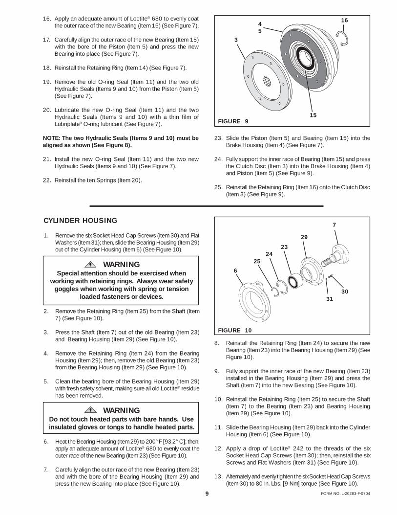
1. Remove the six Socket Head Cap Screws (Item 30) and FlatWashers (Item 31); then, slide the Bearing Housing (Item 29)out of the Cylinder Housing (Item 6) (See Figure 10).
WARNINGSpecial attention should be exercised when
working with retaining rings. Always wear safetygoggles when working with spring or tension
loaded fasteners or devices.
2. Remove the Retaining Ring (Item 25) from the Shaft (Item7) (See Figure 10).
3. Press the Shaft (Item 7) out of the old Bearing (Item 23)and Bearing Housing (Item 29) (See Figure 10).
4. Remove the Retaining Ring (Item 24) from the BearingHousing (Item 29); then, remove the old Bearing (Item 23)from the Bearing Housing (Item 29) (See Figure 10).
5. Clean the bearing bore of the Bearing Housing (Item 29)with fresh safety solvent, making sure all old Loctite® residuehas been removed.
WARNINGDo not touch heated parts with bare hands. Useinsulated gloves or tongs to handle heated parts.
6. Heat the Bearing Housing (Item 29) to 200° F [93.2° C]; then,apply an adequate amount of Loctite® 680 to evenly coat theouter race of the new Bearing (Item 23) (See Figure 10).
7. Carefully align the outer race of the new Bearing (Item 23)and with the bore of the Bearing Housing (Item 29) andpress the new Bearing into place (See Figure 10).
7
29
3031
2324
25
6
FIGURE 10
8. Reinstall the Retaining Ring (Item 24) to secure the newBearing (Item 23) into the Bearing Housing (Item 29) (SeeFigure 10).
9. Fully support the inner race of the new Bearing (Item 23)installed in the Bearing Housing (Item 29) and press theShaft (Item 7) into the new Bearing (See Figure 10).
10. Reinstall the Retaining Ring (Item 25) to secure the Shaft(Item 7) to the Bearing (Item 23) and Bearing Housing(Item 29) (See Figure 10).
11. Slide the Bearing Housing (Item 29) back into the CylinderHousing (Item 6) (See Figure 10).
12. Apply a drop of Loctite® 242 to the threads of the sixSocket Head Cap Screws (Item 30); then, reinstall the sixScrews and Flat Washers (Item 31) (See Figure 10).
13. Alternately and evenly tighten the six Socket Head Cap Screws(Item 30) to 80 In. Lbs. [9 Nm] torque (See Figure 10).
23. Slide the Piston (Item 5) and Bearing (Item 15) into theBrake Housing (Item 4) (See Figure 7).
24. Fully support the inner race of Bearing (Item 15) and pressthe Clutch Disc (Item 3) into the Brake Housing (Item 4)and Piston (Item 5) (See Figure 9).
25. Reinstall the Retaining Ring (Item 16) onto the Clutch Disc(Item 3) (See Figure 9).

10FORM NO. L-20283-F-0704
REASSEMBLY
1. Lubricate the new O-ring Seal (Item 18) with Lubriplate®
O-ring lubricant (See Figure 11).
2. Press the new O-ring Seal into the seal groove in the BrakeHousing (Item 4) (See Figure 11).
3. Slide the Cylinder Housing (Item 6), Bearing Housing (Item29), and Shaft (Item 7) onto the Brake Housing (Item 4)and Clutch Disc (Item 3) (See Figure 11).
4. Apply a drop of Loctite® 242 to the threads of the tenSocket Head Cap Screws (Item 22) (See Figure 11).
5. Reinstall and tighten the ten Socket Head Cap Screws(Item 22) and Flat Washers (Item 28) to 143 In. Lbs. [16.02N•m] torque.
6. Slide the assembled Brake Housing (Item 4) and CylinderHousing (Item 6) onto the Housing (Item 1) (See Figure12).
7. Apply a drop of Loctite® 242 to the threads of the twelveSocket Head Cap Screws (Item 21) (See Figure 12).
8. Reinstall and tighten the twelve Socket Head Cap Screws(Item 21) and Flat Washers (Item 27) to 45 In. Lbs. [5.04N•m] torque.
FIGURE 11
6
184
3
22
InletPort
7
4
1
6
FIGURE 12
28
2127
REPLACEMENT PARTS
The item or balloon number for all Nexen products is used forpart identification on all product parts lists, product pricelists, unit assembly drawings, bills of materials, and instructionmanuals.
When ordering replacement parts, specify model designation,item number, part description, and quantity. Purchasereplacement parts through your local Nexen Distributor.
11 FORM NO. L-20283-F-0704
1712
1
1615
2
1932
319
816
1415
11
20
5
109
18
16
2524
29
3123
30
13
22
7
21
27
266 28
FIGURE 13
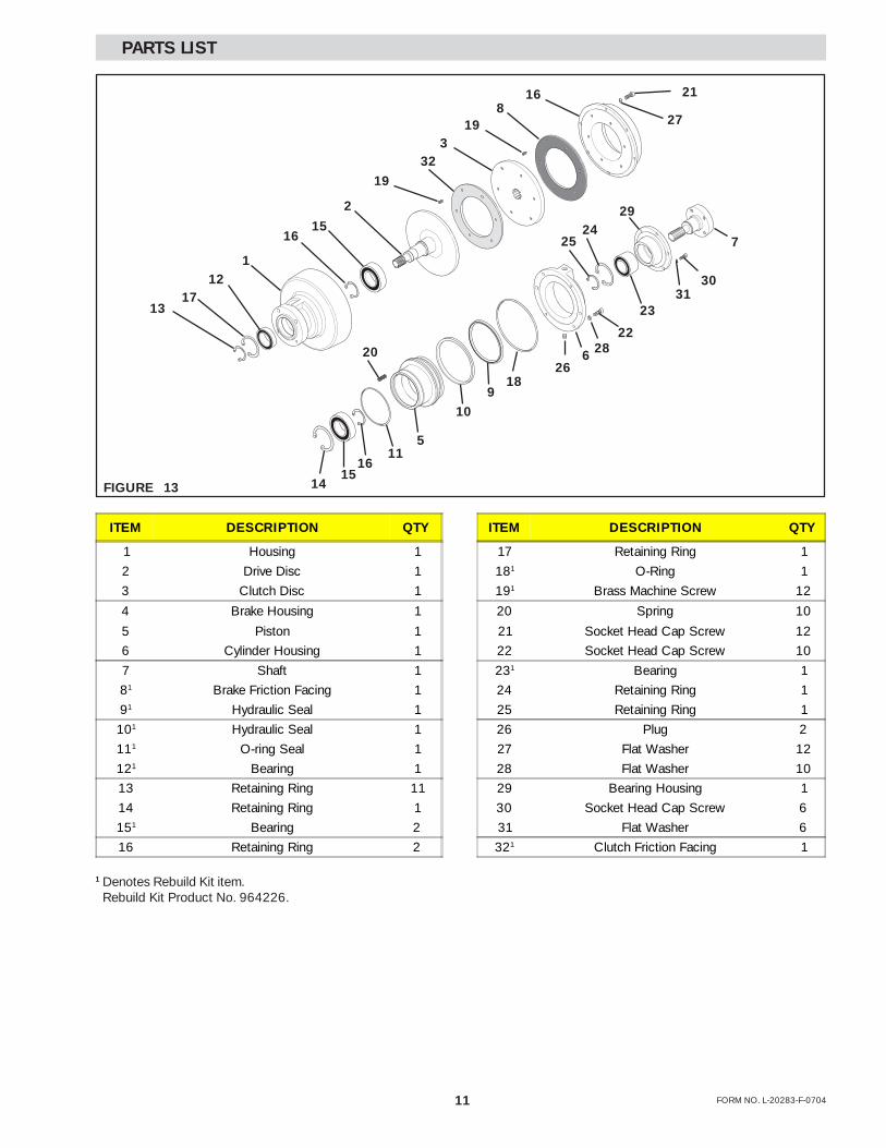
1 Denotes Rebuild Kit item. Rebuild Kit Product No. 964226.
PARTS LIST
ITEM DESCRIPTION QTY ITEM DESCRIPTION QTY
1 Housing 1 17 Retaining Ring 1
2 Drive Disc 1 181 O-Ring 1
3 Clutch Disc 1 191 Brass Machine Screw 12
4 Brake Housing 1 20 Spring 10
5 Piston 1 21 Socket Head Cap Screw 12
6 Cylinder Housing 1 22 Socket Head Cap Screw 10
7 Shaft 1 231 Bearing 1
81 Brake Friction Facing 1 24 Retaining Ring 1
91 Hydraulic Seal 1 25 Retaining Ring 1
101 Hydraulic Seal 1 26 Plug 2
111 O-ring Seal 1 27 Flat Washer 12
121 Bearing 1 28 Flat Washer 10
13 Retaining Ring 11 29 Bearing Housing 1
14 Retaining Ring 1 30 Socket Head Cap Screw 6
151 Bearing 2 31 Flat Washer 6
16 Retaining Ring 2 321 Clutch Friction Facing 1

12FORM NO. L-20283-F-0704
WARRANTY
WarrantiesNexen warrants that the Products will be free from any defects in material or workmanship for a period of 12 monthsfrom the date of shipment. NEXEN MAKES NO OTHER WARRANTY, EXPRESS OR IMPLIED, AND ALL IMPLIEDWARRANTIES, INCLUDING WITHOUT LIMITATION, IMPLIED WARRANTIES OF MERCHANTABILITY AND FIT-NESS FOR A PARTICULAR PURPOSE ARE HEREBY DISCLAIMED. This warranty applies only if (a) theProduct has been installed, used and maintained in accordance with any applicable Nexen installation or maintenancemanual for the Product; (b) the alleged defect is not attributable to normal wear and tear; (c) the Product has not beenaltered, misused or used for purposes other than those for which it was intended; and (d) Buyer has given writtennotice of the alleged defect to Nexen, and delivered the allegedly defective Product to Nexen, within one year of thedate of shipment.
Exclusive RemedyThe exclusive remedy of the Buyer for any breach of the warranties set out above will be, at the sole discretion ofNexen, a repair or replacement with new, serviceably used or reconditioned Product, or issuance of credit in theamount of the purchase price paid to Nexen by the Buyer for the Products.
Limitation of Nexen’s LiabilityTO THE EXTENT PERMITTED BY LAW NEXEN SHALL HAVE NO LIABILITY TO BUYER OR ANY OTHER PERSONFOR INCIDENTAL DAMAGES, SPECIAL DAMAGES, CONSEQUENTIAL DAMAGES OR OTHER DAMAGES OFANY KIND OR NATURE WHATSOEVER, WHETHER ARISING OUT OF BREACH OF WARRANTY OR OTHERBREACH OF CONTRACT, NEGLIGENCE OR OTHER TORT, OR OTHERWISE, EVEN IF NEXEN SHALL HAVEBEEN ADVISED OF THE POSSIBILITY OR LIKELIHOOD OF SUCH POTENTIAL LOSS OR DAMAGE. For all ofthe purposes hereof, the term “consequential damages” shall include lost profits, penalties, delay images, liquidateddamages or other damages and liabilities which Buyer shall be obligated to pay or which Buyer may incur basedupon, related to or arising out of its contracts with its customers or other third parties. In no event shall Nexen be liablefor any amount of damages in excess of amounts paid by Buyer for Products or services as to which a breach ofcontract has been determined to exist. The parties expressly agree that the price for the Products and the services wasdetermined in consideration of the limitation on damages set forth herein and such limitation has been specificallybargained for and constitutes an agreed allocation of risk which shall survive the determination of any court of compe-tent jurisdiction that any remedy herein fails of its essential purpose.
Limitation of DamagesIn no event shall Nexen be liable for any consequential, indirect, incidental, or special damages of any nature whatso-ever, including without limitation, lost profits arising from the sale or use of the Products.
Warranty Claim ProceduresTo make a claim under this warranty, the claimant must give written notice of the alleged defect to whom the Productwas purchased from and deliver the Product to same within one year of the date on which the alleged defect firstbecame apparent.
Nexen Group, Inc.560 Oak Grove ParkwayVadnais Heights, MN 55127
800.843.7445Fax: 651.286.1099www.nexengroup.com
ISO 9001 Certified