Embed Size (px)
Citation preview


EMP Assessment Report – Hi-Quality (Bulla)
3
Contents
Abbreviations 6
Summary 9
1 Introduction 14
1.1 Background 14
1.2 West Gate Tunnel Project roles and responsibilities 14
1.2.1 Waste producer (CPB/JH JV) 14
1.2.2 Waste receiver (Hi-Quality) 15
2 Assessment approach 16
2.1 The Environment Protection Act 1970 17
2.2 Environment effects statement requirement 17
2.3 Subordinate legislation and guidance 18
2.4 Management of Tunnel Boring Machine Spoil Regulation 18
2.5 Relevant waste legislation 19
2.6 Legislative basis 19
3 The West Gate Tunnel Project 21
3.1 Project overview 21
3.2 Estimated volume of spoil 22
3.3 Spoil and groundwater characteristics 22
3.3.1 Geology 23
3.3.2 Potential contaminants 23
3.3.3 Sources of PFAS in soil 23
3.3.4 Sources of other contamination in soil 23
3.3.5 Tunnel alignment exceptions 28
3.3.6 PFAS in Groundwater 29
3.3.7 Other contaminants in groundwater 31
3.3.8 Foaming agents 32
4 Hi-Quality Environment Management Plan 34
4.1 Spoil management proposal 34
4.2 Spoil storage 34
4.3 Soil sampling regime 34
4.3.1 Sampling at the source 34
4.3.2 Sampling at Hi-Quality 34
4.3.3 Spoil from exception zones 34
4.3.4 Spoil analysis 35
4.3.5 PFAS testing regime 35
4.3.6 Spoil water sampling locations and frequency 36
4.3.7 Assumptions 36
4.4 Spoil deposition 36
4.4.1 PFAS Thresholds for containment cell 36

EMP Assessment Report – Hi-Quality (Bulla)
4
4.4.2 Soil categories A, B and C 37
4.5 Spoil 38
4.6 Leachate 38
4.7 Groundwater 39
4.8 Surface water 39
5 Site Description 40
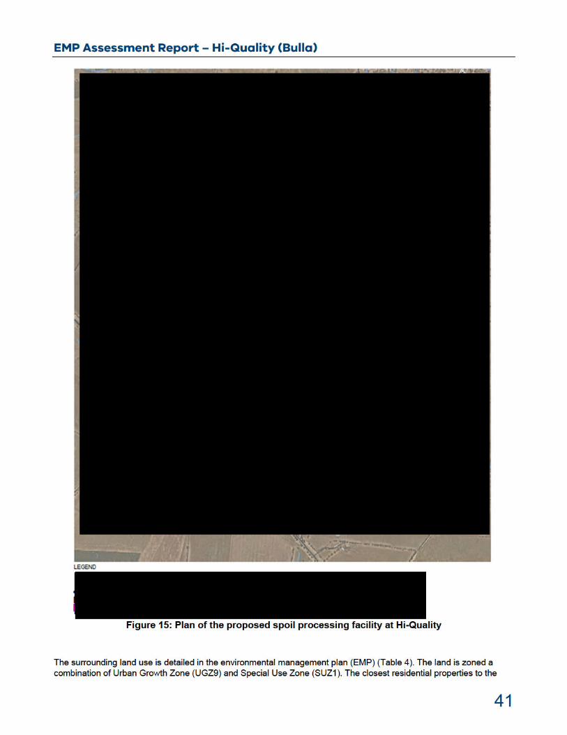
5.1 Location and site layout 40
5.2 Topography and surface waters 42
5.3 Geology 43
5.4 Hydrogeology and groundwater 44
5.4.1 Hydrogeological setting 44
5.4.2 Background levels 44
5.4.3 Beneficial uses 44
5.5 Background PFAS concentrations 45
6 Environmental and Human Health Risk assessment 46
6.1 Human health risk assessment 46
6.1.1 Operational use – on-site 46
6.1.2 Off-site 46
6.1.3 Future use 48
6.2 Ecological risk assessment 48
6.3 Hydrogeological risk assessment 49
6.3.1 Groundwater risk assessment – containment cell, holding bay area and leachate ponds 49
6.4 Containment cell groundwater risk assessment 50
6.4.1 Liner suitability results 52
6.4.2 Uncertainty analysis 52
6.4.3 Limitations and assumptions 53
6.4.4 Liner suitability conclusions 53
6.5 Holding bays – groundwater risk assessment 53
6.6 Leachate pond – groundwater risk assessment 56
6.7 Noise assessment 57
6.7.1 Noise modelling software 57
6.7.2 Construction noise assessment 57
6.7.3 Sleep disturbance 58
6.7.4 Heavy vehicle noise 58
6.7.5 Noise Conclusions 58
7 Detailed Design Assessment 60
7.1 Holding bays design overview 60
7.1.1 Designs 60
7.1.2 Technical specifications and CQAP 63
7.1.3 Holding bay design conclusions 63
7.2 Containment cell design assessment 64
7.2.1 Designs 64
7.2.2 Technical specifications and CQAP 68

EMP Assessment Report – Hi-Quality (Bulla)
5
7.2.3 Containment cell design conclusions 68
7.3 Leachate pre-treatment ponds 68
7.3.1 Design 69
7.3.2 Technical specifications and CQAP 71
7.3.3 Pre-treatment leachate pond design conclusions 72
7.4 Leachate water balance 72
7.5 Leachate treatment 73
8 Environmental Management Assessment 75
8.1 Spoil Management 75
8.1.1 Disposal in the containment cell 75
8.1.2 Containment cell compliance sampling 75
8.1.3 Prescribed industrial waste disposal 76
8.1.4 Existing Soil 76
8.2 Groundwater 76
8.3 Surface water 79
8.4 Leachate 79
8.5 Air quality 80
8.6 Noise/vibration 81
8.7 Other management activities 82
8.8 Rehabilitation 82
8.9 Reporting 83
8.9.1 Pollution Incident Plan 83
8.10 Auditing 83
9 References 85
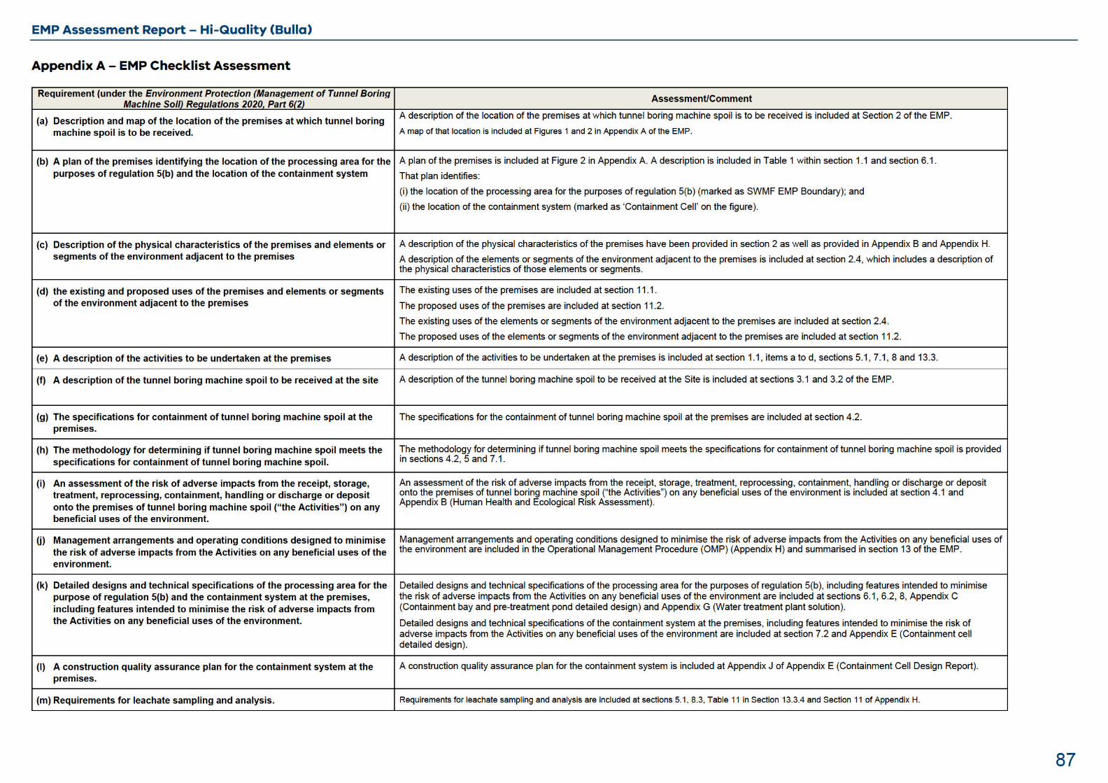
Appendix A – EMP Checklist Assessment 87

EMP Assessment Report – Hi-Quality (Bulla)
6
Abbreviations
ADWG Australian Drinking Water Guideline
ANZECC Australian and New Zealand Environment Conservation Council
AJJV Aurecon-Jacobs Joint Venture
ASLP Australian Standard Leaching Procedure
bgl below ground level
CPB/JH JV CPB John Holland Joint Venture
CQAP construction quality assurance plan
EES environment effects statement
EMP environmental management plan
EP ACT Environment Protection Act 1970
EP MTBMS Regulations Environment Protection (Management of Tunnel Boring Machine Spoil) Regulations 2020
FOS Factor of Safety
GCL geosynthetic clay liner
HDPE high-density polyethylene
HHERA human health and ecological risk assessment
Hi-Quality Hi-Quality Quarry Products Pty Ltd
IWR Regulations Environment Protection (Industrial Waste Resource) Regulations 2009
IWRG621 Industrial Waste Resource Guidelines - Soil Hazard Categorisation and Management
IWRG702 Industrial Waste Resource Guidelines - Soil Sampling
km kilometre
Koc organic carbon partition coefficient
LCM loose cubic metres
LOR limit of reporting
m metre
m3 cubic metre

EMP Assessment Report – Hi-Quality (Bulla)
7
mg/kg milligrams per kilogram
NAPL non-aqueous phase liquid
NEMP National Environmental Management Plan
NYMS North Yarra Main Sewer
OMP Operational Management Procedures
PAH polycyclic aromatic hydrocarbon
PASS potential acid sulfate soil
PFAS per- and poly-fluoroalkyl substances
PFBS perfluorobutanesulfonic acid
PFCA perfluorocarboxylic acid
PFHpA perfluoroheptanoic acid
PFHxA perfluorohexanoic acid
PFHxS perfluorohexane sulfonate
PFOA perfluorooctanoic acid
PFOS perfluorooctane sulfonate
PFPeA perfluoro-n-pentanoic acid
PFSA perfluorosulfonic acid
PIW prescribed industrial waste
QC quality control
SAQP sampling analysis quality plan
SEPP State Environment Protection Policy
SWMF Sunbury Waste Management Facility
SPR source pathway receptor
TBM tunnel boring machine
TDS total dissolved salt
foc total organic carbon
UCL upper confidence limit

EMP Assessment Report – Hi-Quality (Bulla)
8
µg/L micrograms per litre
USEPA United States Environment Protection Agency
VOC volatile organic compound
WGTP West Gate Tunnel Project
WTP wastewater treatment plant

EMP Assessment Report – Hi-Quality (Bulla)
9
Summary
Environment Protection Authority Victoria (EPA) received from Hi-Quality Sales Victoria Pty Limited (Hi-Quality) an Environment Management Plan (EMP) application proposing to receive and manage soil and rock (spoil) generated from the West Gate Tunnel Project (WGTP). This followed a series of technical documents submitted over previous weeks. In addition, EPA received a sample analysis quality plan from CPB/John Holland Joint Venture (CPBJH JV).
It is estimated that a total of 1.5 million cubic metres (m3) (2.8 million tonnes) of spoil will be generated from the construction of the WGTP tunnel. Hi-Quality proposes to receive the spoil at their premises located at 570 Sunbury Road, Bulla VIC 3428 (the Site).
Hi-Quality’s proposal is to:
temporarily stockpile and temporarily store spoil generated from the WGTP within holding bays in order to collect and analyse soil samples for the purpose of categorisation and potential classification; and
permanently deposit categorised spoil into a containment cell area at the Site where suitable to do so, or transportation of spoil for either reuse elsewhere, treatment or disposal at an appropriate facility.
Groundwater investigations along the WGTP tunnel alignment have indicated the presence of per- and poly-fluoroalkyl substances (PFAS). However, the soil and rock from the tunnel alignment has not been sampled for PFAS. To ensure the spoil is appropriately managed, EPA therefore requires that the spoil is to be sampled and analysed prior to reuse, containment, or disposal to landfill. Due to the volume and rate of tunnelling, there will be insufficient storage capacity at the northern portal to store the waste spoil in order to sample and categorise it prior to reuse, containment, or disposal to landfill. Therefore, an off-site location such as that which Hi-Quality is proposing will be required to temporarily stockpile, sample, and dry the waste soil prior to reuse, containment, or disposal to landfill.
To support its application, Hi-Quality submitted a document titled ‘Hi-Quality Products Pty Limited, Hi-Quality Sunbury Waste Management Facility, Environment Management Plan’ prepared by GHD, and dated March 2021. This submission comprised a soil management plan, reuse proposal, human health and ecological risk assessment (HHERA), POLLUTEv7 modelling report, detailed design of temporary storage and containment area (including water treatment system design) and endorsement letter from an independent auditor. Further information was provided with the initial EMP (dated December 2020) and subsequent final version of the EMP (dated March 2021).
EPA assessed Hi-Quality’s submission in accordance with the principles of the Environment Protection Act 1970 (the EP Act 1970), as well as in accordance with relevant subordinate legislation and guidelines.
EPA’s assessment focused on the following areas:
Spoil storage and categorisation procedures, including sampling and analysis plans.
Potential environmental and human health impacts of:
o temporary storage of the spoil within holding bays
o permanent deposition to a containment cell.
Assessment of potential spoil and leachate management impacts to:
o on-site operators and future site users
o groundwater quality
o surface water quality
o stormwater quality
o air quality
o noise.
EPA is satisfied that the proposed spoil management methods are in compliance with the relevant subordinate legislation and the relevant guidelines. EPA is satisfied that all the matters specified in regulation 6(2) of the Management of Tunnel Boring Machine Spoil Regulations are included in the EMP (this is outlined in Appendix A). EPA is satisfied that the EMP, together with the EP MTBMS Regulations adequately protects human health and the environment from the harmful effects of pollution and waste (regulation 6(3)). EPA has reached this state of satisfaction

EMP Assessment Report – Hi-Quality (Bulla)
10
having regard to conclusions 1-42 set out in this summary (see below), as well as the other conclusions addressed throughout the assessment report. In particular, EPA has considered:
assessment of the spoil (conclusions 1-4);
the holding bays (conclusions 5-9);
the containment cell (conclusions 10-13);
the leachate pond and leachate management (conclusions 14-19);
the human health and ecological risk assessment (conclusions 20-27); and
the environmental management (conclusions 28-42)
On that basis EPA approves the EMP under the Environment Protection (Management of Tunnel Boring Machine Spoil) Regulations 2020.
EPA provides the following conclusions from its assessment of the applications.
Soil (spoil) assessment
EPA conclusions
1. The leachable PFOS+PFHxS (perfluorooctanesulfonic acid and perfluorohexane sulfonic acid) concentrations in spoil are likely to range between below laboratory detection (<0.01 µg/L) up to approximately 0.7 micrograms per litre (µg/L), based on the groundwater data provided.
2. The total and leachable concentrations of PFAS will be measured in samples of spoil taken from the holding bay/s. The concentrations of PFAS in water that drains from the soil may differ significantly from those in in-situ groundwater or in the water in the spoil immediately after production of spoil from the tunnel boring activities.
3. Overall, the total mass of dissolved and adsorbed PFAS per unit bulk volume of spoil and spoil water placed in the containment cell should be lower than the equivalent mass within the soil and groundwater prior to excavation, due to the drainage of the liquid component that would have occurred.
4. The proposed spoil categorisation and disposal management procedure are considered appropriate, and in compliance with the relevant subordinate legislation and the guidelines.
Hi-Quality’s holding bays
EPA conclusions
5. EPA is satisfied that the Auditor assessed holding bays design documents provided in the EMP, contain sufficient provisions to adequately manage environmental risks that may arise during holding bay construction and operation, and ensure the holding bays are constructed in accordance with the design.
6. The approach to modelling PFAS transport, in the hydrogeological risk assessment, across the liner of the holding bays is likely conservative as it does not consider provisions for surface drainage or the short timescale of the project. It also assumes a constant leachate head of PFAS-containing leachate across the whole of the holding bay area for the duration of the project. Given the intermittent use of bays this likely overestimates seepage.
7. The profile that is adopted in the holding bay design documents is a subgrade. This profile, in combination with the 40 m subgrade, is considered protective of
groundwater beneficial uses even with high PFAS concentrations and the assumptions outlined above.
8. In the absence of the 40 m subgrade, the model suggests that the chosen liner would not be protective of groundwater beneficial uses given a 5-year timeline. However, this is based on assumptions detailed above.
9. Even under the worst-case conditions modelled, penetration of PFAS was found to be unlikely to reach groundwater due to the substantial unsaturated zone in the area. The model indicates some penetration into this layer. However, as noted this is based on conservative assumptions which likely overestimate seepage and time available for seepage. It is interpreted that given the chosen liner and the holding bay seepage is likely to be low with little reliance on the subgrade.

EMP Assessment Report – Hi-Quality (Bulla)
11
Hi-Quality’s containment cell
Siting and design
EPA conclusions
10. EPA is satisfied that the Auditor assessed containment cell and cap design documents provided in the EMP, contain sufficient provisions to adequately manage environmental risks that may arise during containment cell construction and operation, and ensure the containment cell and cap are constructed in accordance with the design.
11. The proposed liner for the containment cell has . Modelling of the
profile in combination with the 6 m separation from groundwater, was found to be protective of the beneficial uses of the underlying groundwater within the 100-year model time given PFOS or PFOA concentrations of 10.7 µg/L and 330 µg/L (above the proposed acceptance criteria) . Conservatively this is in the absence of accounting for any dilution in the aquifer. The modelling indicates some reliance on the subsurface providing attenuation of PFAS which may have uncertainty related to its composition and the behaviour of PFAS. This should be considered in combination with the inherent assumptions discussed further in section 6.4.
12. The model’s outcomes being realised are also contingent on suitable construction quality control and construction quality assurance to ensure the liner materials perform to specifications. The Technical Specifications and CQAP indicate an adherence to industry best practice (section 7.2.2).
13. Based on the proposed controls and management of the soil, adopting the disposal criteria in the PFAS NEMP is a conservative option. The risk assessment justifies taking a less conservative approach, but there are residual uncertainties. An alternative approach would be to use the Industrial Waste Resource Guidelines (IWRG) process for other chemicals (multiplying drinking water criteria by 100). This would result in a criteria of . While this approach is not primarily driven by the site-specific risk assessment, it is consistent with it. The reduction in the acceptance criteria to this value provides a safety margin given the remaining uncertainties in regards the interaction of PFAS with landfill liner materials, uncertainties in flow through the unsaturated zone and the behaviour of PFAS in the environment.
Hi-Quality’s leachate pond and leachate management
EPA conclusions
14. EPA is satisfied that the leachate pre-treatment pond designs provided in the EMP, contain sufficient provisions to adequately manage environmental risks that may arise during pre-treatment ponds construction and operation.
15. The leachate water balance has been prepared using conservative assumptions in that it is assuming high volumes of leachate production.
16. EPA is satisfied that the system is then designed to be able to manage the resulting leachate volumes and that redundancy to cope with high volumes of leachate will be available. The water balance, therefore, supports the proposed leachate management for the Site. All leachate collected will be transferred to the water treatment plant and PFAS will be removed to below 0.02 µg/L for total PFAS.
17. As with the holding bay area modelling, the model indicates some reliance on the properties of the 40 m subsurface layer (aquitard) being realised. However, the general approach to modelling parameters is likely to be conservative and EPA is satisfied that even if the aquitard is not as effective regarding attenuation the design would be sufficiently protective.
18. The EMP risk-based acceptance criteria for the leachate ponds is 250 µg/L (perfluorocarboxylic acids (PFSA’s) and perfluorosulfonic acids (PFCA’s)), based on ecological protection values derived in the HHERA. This is significantly higher than the spoil leaching waste acceptance criteria and far in excess of the groundwater concentrations in the tunnel alignment to date. Such a high acceptance criterion for the leachate ponds may put a higher reliance on the 40 m subsurface layer properties being realised. Therefore, the EMP states that although higher concentrations could be contained within the ponds, a more conservative upper
EMP Assessment Report – Hi-Quality (Bulla)
12
value is adopted: . It is noted that this value is also in excess of the anticipated concentrations in the leachate but is sufficient to minimise potential impacts to groundwater.
19. Leachate is proposed to be treated through a water treatment plant consisting of A proposed criteria for reuse of
treated water is the Australian Drinking Water Guidelines. The system has been designed to treat water down to between non-detect and 0.02 µg/L for total PFAS. Treated wastewater will either be reused on site or disposed to a site licensed to accept the waste.
Hi-Quality’s human health and ecological risk assessment (HHERA)
EPA conclusions
20. The assumptions used in the derivation of the site-specific trigger levels are suitably conservative.
21. Exposure pathways were considered further in the HHERA and incidental ingestion of leachate and dust formed the basis of deriving the site-specific trigger levels for PFCAs and PFSAs.
22. The HHERA states that the modelling predicts that a lining system of will be effective in containing material with
quite elevated PFAS concentration to within Australian drinking water criteria.
23. The assumption in the HHERA that there will be no PFAS impacts to groundwater beneficial uses as a result of leaching from the containment area is based on liner performance modelling.
24. The HHERA states that the SPR linkage for direct contact with spoil and leachate in the containment area (intrusive maintenance workers) is incomplete as exposure to spoil and leachate will not occur due to the area being capped in accordance with EPA Publication 788.3. This is considered to be a reasonable assumption.
25. The HHERA appears to consider the health of the ecological receptors such as water birds.
26. The Site must restrict access of birdlife to the on-site leachate ponds.
27.
Hi-Quality’s environmental management
Spoil
EPA conclusion
28. The proposed acceptance criteria for the spoil at the site is above EPA’s interim criteria for reuse (as per EPA Publication 1669.3). Therefore, some management and controls measures must be in place, such as placement in a containment cell, as proposed.
Groundwater
EPA conclusions
29. The EMP proposes a sufficient groundwater monitoring program to monitor for potential changes to groundwater quality.
30. All leachate management will be undertaken within appropriately lined areas to prevent potential groundwater contamination.
31. Additional groundwater monitoring bores are proposed to be installed around the proposed spoil bays and containment area. These will be required to monitor the groundwater during and after operation.
32. As part of the audit process, records of the monitoring data (including PFAS) will be checked.
Surface water
EPA conclusion
33. 95 per cent species protection level for PFOS (0.13 µg/L) is acceptable with ambient data (water, sediment and biota) collected for the Site.

EMP Assessment Report – Hi-Quality (Bulla)
13
34. Ambient levels of PFAS in water and sediment are proposed to be obtained. This sampling will be conducted before the receipt of spoil.
35. Regular monitoring of surface waters will be undertaken to monitor for potential changes in surface water quality. Monitoring will include PFAS sampling for water and sediment.
36. As part of the audit process, records of the biannual and annual monitoring data (including PFAS) will be checked.
Noise/vibration
EPA conclusions
37. Minimising noise as far as reasonably practicable – for both construction works and operations – must be considered prior to considering compliance to the relevant noise limits or criteria.
38. Where there are no noise criteria provided on the guidelines, the most appropriate approach is to demonstrate application of requirements of the guidelines and measures implemented to reduce noise/vibration and their impacts.
39. Consideration must be given to addressing the potential issue of low frequency noise which may occur during construction and while the spoil processing and management facility is operational.
40. Follow-up assessment of the effective implementation of noise mitigation measures will be undertaken to verify compliance with State Environment Protection Policy (Control of noise from industry, commerce and trade) No, N-1 (SEPP N-1) once spoil processing and management facility is operational.
Rehabilitation
EPA conclusions
41. Details of proposed assessment and monitoring post removal of temporary infrastructure and completion of works appears to be appropriate. The EMP proposes to
42. A detailed rehabilitation and after-care management plan shall be provided to EPA for review prior to receipt of the final load of spoil.

EMP Assessment Report – Hi-Quality (Bulla)
14
1 Introduction
EPA received an Environment Management Plan (EMP) from Hi-Quality Sales Victoria Pty Limited (Hi-Quality) proposing to receive and manage soil, rock and water (spoil) generated from the West Gate Tunnel Project (WGTP). This application was followed by a sample analysis quality plan (SAQP) from CPB/John Holland Joint Venture (CPB/JH JV). CPB/JH JV will be responsible for the generation of the spoil, transportation to a site with an approved EMP and for sampling and characterisation of the spoil and spoil water prior to containment, reuse or disposal. A receiving site such as Hi- Quality will be responsible for the temporary stockpiling, containment and management of environmental controls at the receiving site.
It is estimated that a total of 1.5 million cubic metres (m3) (2.8 million tonnes) of spoil will be generated from the construction of the WGTP tunnel. Hi-Quality proposes to receive the spoil at its premises located at 570 Sunbury Road, Bulla VIC 3428 (the Site).
Hi-Quality’s proposal is to develop their Sunbury Waste Management Facility (SWMF) to:
temporarily stockpile and temporarily store spoil generated from the WGTP within holding bays in order to collect and analyse spoil samples for the purpose of categorisation and potential classification; and
permanently deposit categorised spoil into a containment cell area at the Site where suitable to do so, or transportation of spoil for either reuse elsewhere, treatment or disposal at an appropriate facility.
The containment cell is proposed for construction within a gully at the Site, which has been identified under the Sunbury South Precinct Structure Plan for redevelopment with potential end use of commercial and industrial land use.
In accordance with the Environment Protection (Management of Tunnel Boring Machine Spoil) Regulations 2020, Hi-Quality has submitted the following documentation for EPA's assessment:
‘Hi-Quality Quarry Products Pty Limited, Sunbury Waste Management Facility Environmental Management Plan’, prepared by GHD, dated December 2020, subsequently revised to version dated March 2021.
‘Assessment of suitability of the detailed designs, technical specifications, construction quality assurance plan, monitoring program and pollution incident plan in achieving the requirements and objectives of the Regulations’, prepared by Nolan Consulting (Environmental Auditor), dated 15 December 2020, subsequently revised to version dated 4 March 2021.
EPA has reviewed the applicant’s documents and critically assessed the data and information to inform this assessment.
1.1 Background
The WGTP is a project that will provide an upgrade to the West Gate Freeway and a connection from the West Gate Freeway to the CityLink toll road.
Approximately 1,500,000 m3 of the spoil, which can include soil, rock and water, is expected to be generated from two tunnel boring machines, excavated from the tunnel alignment.
Assessment reports indicate that groundwater is likely to be contaminated with per- and poly-fluoroalkyl substances (PFAS) along the tunnel alignment. Coastal acid sulfate soils are also potentially present in small quantities in the area of the former Stony Creek Alignment.
Hi-Quality has applied under the Environment Protection (Management of Tunnel Boring Machine Spoil) Regulations 2020 to receive and manage spoil form the tunnel alignment.
1.2 West Gate Tunnel Project roles and responsibilities
1.2.1 Waste producer (CPB/JH JV) The waste producer will be responsible for:
managing the waste spoil, and treatment of excess wastewater at the northern portal/Pivot site
daily observation of odour and visual appearance of spoil
EMP Assessment Report – Hi-Quality (Bulla)
15
daily sampling of the soil and water released from the spoil at Hi-Quality’s site as per the SAQP and classification
transport of the spoil from the northern portal/Pivot site to the Hi-Quality site
daily tracking of waste spoil volumes and movements
disposal of waste spoil unsuitable for reuse or storage in containment cell to a licensed facility
production of EPA classification compliance reports.
1.2.2 Waste receiver (Hi-Quality) The waste receiver will be responsible for:
managing the temporary storage of the waste spoil prior to disposal, permanent containment or reuse
tracking of material received
construction of temporary storage bays and containment cell
general site management, including potential air quality, noise, surface water and other environmental impacts on the Site
management, including treatment of waste waters including leachate and surface water generated for the storage and management of the waste soils
monitoring groundwater and surface waters for potential changes in environmental conditions.

EMP Assessment Report – Hi-Quality (Bulla)
16
2 Assessment approach
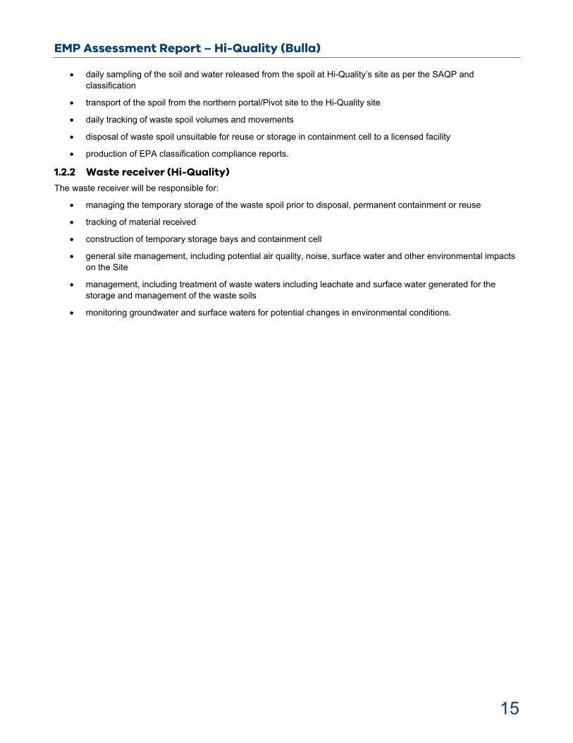
EPA’s assessment process has considered the following key issues (with a generic conceptual site model giving an overview in Figure 1):
The characterisation of the WGTP spoil, including potential contaminants within extracted spoil and groundwater
The proposed spoil management including:
o storage of the spoil within holding bays
o spoil sampling and analysis regime and methodology
o suitability of the spoil deposition.
Environmental and human health risks of the proposed deposition of spoil to a containment cell
Human health risks, including:
o risk to human health of on-site operational activities associated with the management of the spoil
o off-site impacts of the on-site operational activities associated with the management of the spoil
o potential impacts to the future use of the Site.
o noise impacts.
Environmental risks, including potential environmental impacts of the proposed temporary spoil storage in holding bays and permanent deposition to a containment cell. The assessed approaches include leachate treatment and management, stormwater management and groundwater management.
Environmental management and monitoring of:
o spoil characteristics
o groundwater quality
o surface water quality
o leachate
o air quality
o noise
Rehabilitation of the Site.
EMP Assessment Report – Hi-Quality (Bulla)
17
Figure 1: A generic conceptual site model of the spoil receiving site.
This highlights potential pathways and receptors, in addition to the controls that will be assessed.
2.1 The Environment Protection Act 1970
Management of contaminated soil is not specifically addressed in the Environment Protection Act 1970 (EP Act). However, the Act contains a range of relevant regulatory requirements.
Contaminated soil generated by infrastructure projects is industrial waste. Therefore, the excavations and management of such soil must be conducted in accordance with the EP Act, including the principles of the EP Act, relevant subordinate legislation and instruments under the EP Act.
The principles of the EP Act of most relevance for this proposal are:
1B Principle of integration of economic, social and environmental considerations
1C The precautionary principle
1D Principle of integrational equity
1I Principle of wastes hierarchy; and
1K Principle of integrated environmental management.
2.2 Environment effects statement requirement
On 23 December 2015, the Victorian Minister for Planning declared the works proposed for the WGTP as ‘public works’ requiring an environment effects statement (EES).
The key regulatory instruments that govern the management of contaminated soil in Victoria are identified in the EES prepared for the WGTP.
EMP Assessment Report – Hi-Quality (Bulla)
18
The EES, issued in November 2017, identified an extensive list of environmental performance requirements to ensure any adverse local effects are minimised.
2.3 Subordinate legislation and guidance
EPA has assessed the project’s compliance with applicable Regulations, waste management policies and Victorian State Environment Protection Policies (SEPP) including but not limited to:
Environment Protection (Industrial Waste Resource) Regulations 2009
Environment Protection (Management of Tunnel Boring Machine Spoil) Regulations 2020
Environment Protection (Scheduled Premises and Exemptions) Regulations 2017
EPA Publication 1669.3 – Interim Position Statement of PFAS
EPA Publication IWRG701; Industrial Waste Resource Guidelines – Sampling and analysis of waters, wastewaters, soils and wastes
EPA Publication IWRG702; Industrial Waste Resource Guidelines – Soil sampling
Industrial Waste Management Policy (Waste Acid Sulphate Soils) 1999
National Environment Protection (Assessment of Site Contamination) Measure 2013
Relevant Industrial Waste Resources Guidelines
SEPP – Air Quality Management 2001 (in respect of odour)
SEPP – Prevention and Management of Contaminated Land, 2002
Worksafe Occupational Health and Safety Regulations 2007 (Asbestos).
2.4 Management of Tunnel Boring Machine Spoil Regulation
Environment Protection (Management of Tunnel Boring Machine Spoil) Regulations 2020 (EP MTBMS Regulations) which took effect from 30 June apply to TBM spoil. The new EP MTBMS Regulations provide a mechanism for the management and disposal of TBM spoil to protect human health and the environment. While TBM spoil is mostly virgin excavated spoil, some of the WGTP spoil is likely to contain low levels of contaminants including PFAS.
EP MTBMS Regulations set up a framework to appropriately manage spoil ensuring the process is safe for the community and the environment. In accordance with the EP MTBMS Regulations, a site occupier wishing to receive TBM spoil can submit an EMP demonstrating that TBM spoil can be managed in a safe manner so that its risks to the groundwater, surface water and air quality are mitigated.
Key components of the EMP must be verified by an auditor appointed under “Industrial Facilities Category” or “Contaminated Land Category”. EPA’s role under the EP MTBMS Regulations is to review, approve and ensure compliance. The auditor is required to conduct a risk of harm audit and assess the suitability of key plans in achieving the requirements of the Regulations. Clause 6(2)(q) of the regulation reflects section 53V of the EP Act 1970. Moving forward, the auditor may conduct the environmental audit under the EP Act 1970 or EP Act 2017.
EPA’s assessment of Hi-Quality’s EMP in accordance with the EP MTBMS Regulations is provided in Appendix A8.1.

EMP Assessment Report – Hi-Quality (Bulla)
19
2.5 Relevant waste legislation
The WGTP EES, issued in November 2017, identified an extensive list of environmental performance requirements to ensure any adverse local effects are minimised. The environmental performance requirements require the proponent to manage contaminated soil in accordance with environmental legislation and EPA's waste management hierarchy.
Under the provision of the EP Act, there are layers of regulatory requirements which can be applied to the management of contaminated soil. These are found across the EP Act, Regulations, SEPPs and other materials (such as the National Environment Protection (Assessment of Site Contamination) Measure 1999)). Where contaminated soil constitutes waste, and therefore industrial waste, it will be subject to the requirements of the Environment Protection (Industrial Waste Resource) Regulations 2009 (the IWR Regulations).
Schedule 1 of the IWR Regulations lists a series of industrial wastes that are automatically exempt from Regulations. All other industrial waste would be subject to a hazard assessment unless the material has a direct beneficial reuse. Liquid industrial wastes not discharged to sewer, and solid industrial wastes classified as Category A, B or C are defined as ‘prescribed industrial waste’.
The basis for contaminant thresholds is not specifically detailed in the IWR Regulations. The framework for soil hazard categorisation and the basis for contaminant thresholds are provided through the supporting guidelines (IWRG621, IWRG631). The IWRG621 provides hazard categorisation thresholds for a series of analytes but does not include PFAS.
PFAS is an emerging contaminant, and the categorisation and management of PFAS waste is necessary to assist with compliance with the EP Act, relevant subordinate legislation and instruments under the EP Act and the guidelines. The relevant legislations and guidance are provided in section 2.3.
The Provisions of the IWR Regulations impose requirements on three classes of persons concerning the management of PIW, each of which are separately defined in clause 5(1) of the IWR Regulations. The three classes of persons are the waste producer, the waste transporter and the waste receiver.
Under section 27A(1)(b) of the EP Act, it is an indictable offence to contravene any Regulations relating to industrial waste.
EPA can classify waste as PIW or non-PIW under certain conditions. If a person, to which the Classification applies, is not handling the waste in compliance with the Classification, the person may be committing an offence under the EP Act.
As per the Classification, spoil must be transported using appropriate vehicles. Under the current procedure, transporters are required to submit a declaration at the time of applying for a permit, declaring their vehicle satisfies the design requirements.
2.6 Legislative basis
The tunnel components of the WGTP will involve excavations of significant volumes of potentially contaminated soil that cannot be deposited or reused at the point of excavation.
The EP Act contains various provisions which, depending on the circumstances, may apply to the management of contaminated soil.
The Environment Protection (Management of Tunnel Boring Machine Spoil) Regulations 2020 provides a mechanism for the management and disposal of tunnel boring machine spoil to protect human health and the environment. They provide for the occupier of a premises to apply to EPA for approval of an Environment Management Plan (EMP) and requires the occupier to manage tunnel boring machine spoil in accordance with an approved plan. It specifies the elements that must be included in the plan and specifies further parameters that must be complied with.
It is considered that an EMP approved under the Environment Protection (Management of Tunnel Boring Machine Spoil) Regulations 2020 is the appropriate regulatory tool to manage the receipt, dewatering, and containment of the waste.

EMP Assessment Report – Hi-Quality (Bulla)
20
EPA can approve the transport of contaminated soil to non-licensed or non-exempt premises for the purpose of reuse or recycling in accordance with the principle of the waste hierarchy. Alternatively, EPA can issue a classification in respect of contaminated soil, to define the regulatory requirements and management options which may apply to it.

EMP Assessment Report – Hi-Quality (Bulla)
21
3 The West Gate Tunnel Project
3.1 Project overview
The WGTP consists of three zones, being the West Zone, the East Zone and the Tunnel Zone and two portals (the Northern and Southern portals). The three zones are described as:
The West Zone (W200) comprises an upgrade and widening of the West Gate Freeway from the M80 interchange to Williamstown Road, Yarraville.
The East Zone (E400) comprises an elevated road structure from the tunnel’s northern portal in Footscray to the CityLink toll road in North Melbourne.
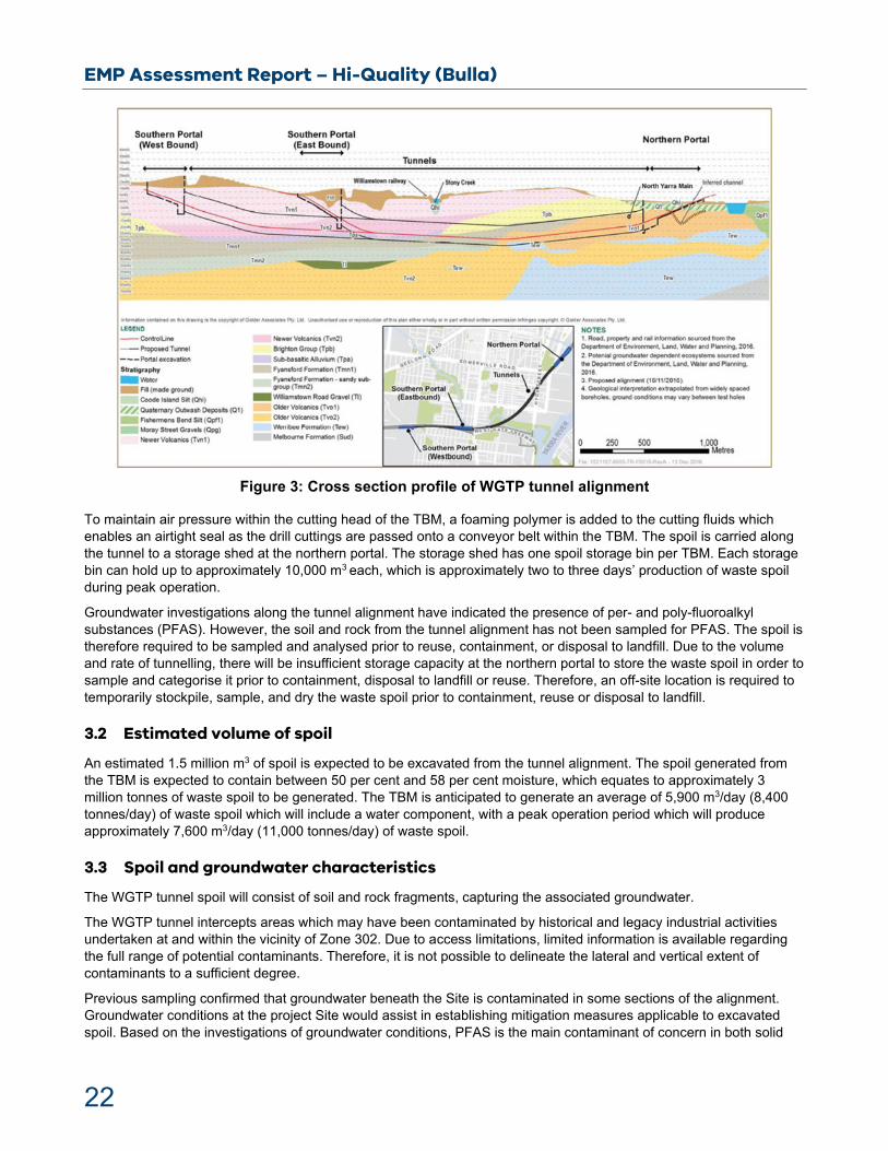
The Tunnel Zone (T300) comprises two 15.6 metre (m) wide tunnels to be excavated beneath Yarraville using tunnel boring machines (TBMs) (refer to Figure 2 and Figure 3).
One of the tunnels is approximately 4 kilometres (km) long, the other is 2.8 km long, and both are excavated to a depth between approximately 10 m and 40 m below the ground. The TBMs will start at the northern portal and progress south towards the two separate southern portals at an average rate of 9 m per day. It is estimated that a total of 1.5 m3 (2.8 million tonnes) of spoil, as well as groundwater, will be generated and/or extracted from the construction of the tunnel.
Figure 2: Extent of WGTP tunnel alignment (Zone 300)
EMP Assessment Report – Hi-Quality (Bulla)
22
Figure 3: Cross section profile of WGTP tunnel alignment
To maintain air pressure within the cutting head of the TBM, a foaming polymer is added to the cutting fluids which enables an airtight seal as the drill cuttings are passed onto a conveyor belt within the TBM. The spoil is carried along the tunnel to a storage shed at the northern portal. The storage shed has one spoil storage bin per TBM. Each storage bin can hold up to approximately 10,000 m3 each, which is approximately two to three days’ production of waste spoil during peak operation.
Groundwater investigations along the tunnel alignment have indicated the presence of per- and poly-fluoroalkyl substances (PFAS). However, the soil and rock from the tunnel alignment has not been sampled for PFAS. The spoil is therefore required to be sampled and analysed prior to reuse, containment, or disposal to landfill. Due to the volume and rate of tunnelling, there will be insufficient storage capacity at the northern portal to store the waste spoil in order to sample and categorise it prior to containment, disposal to landfill or reuse. Therefore, an off-site location is required to temporarily stockpile, sample, and dry the waste spoil prior to containment, reuse or disposal to landfill.
3.2 Estimated volume of spoil
An estimated 1.5 million m3 of spoil is expected to be excavated from the tunnel alignment. The spoil generated from the TBM is expected to contain between 50 per cent and 58 per cent moisture, which equates to approximately 3 million tonnes of waste spoil to be generated. The TBM is anticipated to generate an average of 5,900 m3/day (8,400 tonnes/day) of waste spoil which will include a water component, with a peak operation period which will produce approximately 7,600 m3/day (11,000 tonnes/day) of waste spoil.
3.3 Spoil and groundwater characteristics
The WGTP tunnel spoil will consist of soil and rock fragments, capturing the associated groundwater.
The WGTP tunnel intercepts areas which may have been contaminated by historical and legacy industrial activities undertaken at and within the vicinity of Zone 302. Due to access limitations, limited information is available regarding the full range of potential contaminants. Therefore, it is not possible to delineate the lateral and vertical extent of contaminants to a sufficient degree.
Previous sampling confirmed that groundwater beneath the Site is contaminated in some sections of the alignment. Groundwater conditions at the project Site would assist in establishing mitigation measures applicable to excavated spoil. Based on the investigations of groundwater conditions, PFAS is the main contaminant of concern in both solid

EMP Assessment Report – Hi-Quality (Bulla)
23
and water fractions of the tunnel waste. PFAS have been detected in bore water samples within the project area. The management of PFAS-contaminated soil and groundwater is important due to the environmental persistence of PFAS.
In addition, Potential Acid Sulfate Soils (PASS), hydrocarbons, chlorinated hydrocarbons, volatile organic compounds (VOCs), naturally occurring metals and metalloids are expected to be present within a few domains of the tunnel alignment. Other contaminants in groundwater may include hydrocarbons, benzene, chlorinated solvents, PAHs and organochlorine pesticides at low concentrations.
EPA recognises that TBM will create a homogeneous material mixing the different lithology. Therefore, there is the potential for a change in contaminant concentrations once the material is removed from the tunnel. During project works, the temperature of the spoil in the TBM excavation chamber may rise up to 50 degrees Celsius. This temperature is expected to reduce the concentrations of some VOCs which may be present in soil.
3.3.1 Geology
The ground conditions include anthropogenic fill, upper basalt rock, soft ground and lower basalt rock. There is a correlation between geological characteristics and spatial and vertical distribution of contaminants. Some attenuation is likely, via differential dispersion, diffusion, sorption and degradation of the different contaminants. Some of the geological formations are likely to contain naturally elevated nickel and arsenic.
The tunnel intersects geological formations such as Newer Volcanic, Older Volcanic, Brighton Group and Fyansford Formation. Older Volcanic outcrops occur across the northern portal. These geological and hydrological settings influence the fate and transport of contaminants at the project site.
3.3.2 Potential contaminants Based on the results of previous soil investigations, CPB/JH JV has reported that, apart from identifiable zones of the project (see sections 3.3.4 and 3.3.5 below), the solids fraction of the in-situ ground in the tunnel alignment has no potential contaminants, except for PFAS.
Elevated concentrations of metals were reported in soil samples collected by the project. However, based on the geology and depth, these were deemed to be naturally occurring.
Anthropogenic chemicals have been detected at low levels in some of the groundwater wells. These include petroleum hydrocarbons, chlorinated solvents, polycyclic aromatic hydrocarbons (PAHs) and pesticides. Several aqueous-phase contaminants were present in sampled groundwater. The concentrations of some heavy metals in groundwater and soil samples are deemed by the project as being reflective of ambient conditions, and the concentrations of other groundwater contaminants are likely to be too low to affect the waste classification of soils/rock to be excavated as tunnel spoil.
3.3.3 Sources of PFAS in soil Based on the observed pattern of PFAS in the groundwater within the tunnel alignment, PFAS have originated from a mix of multiple, dispersed, point and diffuse sources. The exact sources of PFAS plumes cannot be determined without extensive investigations.
PFAS is associated with historic fire-fighting activities and training activities involving the use of aqueous film forming foam that contained PFOS, PFHxS and PFOA. PFOS is expected to be a dominant contaminant in the soil. Groundwater samples near the tunnel alignment contain reported concentrations of PFAS (total) up to 1.12 µg/L, PFOS up to 0.43 µg/L, PFHxS up to 0.21 µg/L and PFOA up to 0.07 µg/L. Higher concentrations have been reported further from the tunnel alignment as described in section 3.3.6, below.
All the West Gate Tunnel Project domains along the tunnel alignment are considered potentially contaminated with PFAS for the purposes of managing the tunnel spoil. The concentrations are likely to be spatially and vertically variable. Shallow soils are likely to contain higher PFAS concentrations than the bulk of the soil to be removed along the alignment at the depth of the tunnel.
3.3.4 Sources of other contamination in soil A desktop assessment has been carried out by the CPB/JH JV’s consultants to determine if acid sulfate soil may be present in the tunnel alignment. Specific geological formations such as Fyansford Formation (Newport Formation), which overlies the Coode Island Silt, may consist of PASS. PASS is geological material containing metal sulfides exceeding criteria in EPA Publication 655 – Acid Sulfate Soil and Rock. PASS may become oxidised following excavation. PASS

EMP Assessment Report – Hi-Quality (Bulla)
24
may be present in black coloured soil with high organic content, enriched with iron monosulfide. The SAQP includes interpretation of the field indicators and action required. Acid sulfate soil may be present in the tunnel alignment. The percentage of the tunnel face that would encounter the Fyansford Formation is conservatively reported as being significantly less than 50 per cent. PASS generally occurs at very low concentrations. However, at elevated concentrations, the risk of harm if not managed appropriately becomes greater. The tunnel soil is clay rich, and clay rich soils generally have a higher natural pH buffering capacity than clay-poor soils. If required, soil alkalinity must be maintained by chemical means to reduce oxidation rate.
Residual soil in Newer Volcanic basalt and Older Volcanic basalt is enriched with nickel, ranging in concentrations from 90 to 450 mg/kg. The maximum concentration of arsenic within residual soil in Older Volcanic basalt is 860 mg/kg. Arsenic concentrations in soil derived from Fyansford Formation are also high. The distribution of arsenic and nickel is influenced by specific adsorption of metals on iron oxide. Newer Volcanic and Older Volcanic occurs west of Maribyrnong River, and outcrops across the majority of the tunnels. The leachability of naturally elevated arsenic and nickel is unlikely to be an issue provided such waste is deposited in a composite-lined cell.
North Yarra Main Sewer (NYMS), which directly intersects the tunnel alignment, is a potential contamination source. Construction would involve relocation of some utilities including a segment of the NYMS between Sommerville Road and Youell Street, Yarraville. This area has been identified as Domain 2, and a relatively small volume soil that is contaminated with other chemicals is likely to be generated from this domain.
Historical activities within northern portal include filling of the former Footscray depression (up to ~10 m) and former use of the site as a State Electricity Commission terminal/depot, gasworks, smelting works, and fertiliser manufacturing plant. The material used to infill the swamp may include waste materials from nearby chemical sites.
The tunnel passes through a highly disturbed area of Yarraville, which has a history of chemical manufacturing and petroleum storage. The south inbound portal is associated with the filling of Stony Creek and the industrial activities which have occurred within the surrounding area. The south outbound portal area occurs where James Hardie and Bradmill manufacturing plants were located.
Characteristics and potential contaminants of concern near the portals include pH, metals (lead, arsenic, copper, zinc), petroleum hydrocarbons, phenolic compounds, chlorinated hydrocarbons, aromatic hydrocarbons, benzo(a)pyrene, organochlorine pesticides, polychlorinated biphenyls, PFAS and asbestos.
As shown in the conceptual cross section in Figure 3, the geochemical and stratigraphical conditions of the ground at the level of, and in the tunnel alignment, are variable. This would create local scale variability in the distribution and concentration of adsorbed and dissolved anthropogenic contaminants.
Based on results from groundwater sampling, PFAS is likely to be present in the tunnel alignment at concentrations that would be above the PFAS reuse criteria concentrations in EPA publication 1669.3. The spoil would therefore require deposition in a composite-lined containment or landfill cell.
EPA does not regulate the use of soil categorised as natural Fill Material (as per IWRG Publication 621). However, soil with elevated levels of metals still requires careful management. Soil with elevated levels of metals may be required to be disposed to landfill to prevent adverse impacts on the environment and on human health.
A series of conceptual site models have been produced by CPB/JH JV’s consultants that demonstrate potential contaminants and geological formations along the alignment. These are described below. Conceptual site model cross sections are presented in Figures 4–10.

EMP Assessment Report – Hi-Quality (Bulla)
25
Figure 4: Conceptual site model cross section 1 – south westbound portal
Figure 5: Conceptual site model cross section 2 – south eastbound portal
EMP Assessment Report – Hi-Quality (Bulla)
26
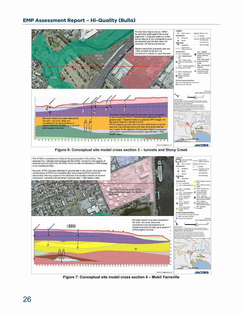
Figure 6: Conceptual site model cross section 3 – tunnels and Stony Creek
Figure 7: Conceptual site model cross section 4 – Mobil Yarraville

EMP Assessment Report – Hi-Quality (Bulla)
27
Figure 8: Conceptual site model cross section 5 – Orica site
Figure 9: Conceptual site model cross section 6 – former Pivot plant

EMP Assessment Report – Hi-Quality (Bulla)
28
Figure 10: Conceptual site model cross section 7 – north portal
3.3.5 Tunnel alignment exceptions
The following areas have been identified as likely being an exception to the bulk of the tunnel alignment, with regards to the presence and combination of potential contaminants.
Original North Yarra Main Sewer alignment
The North Yarra Main Sewer extends for about 50 m and approximately between Tunnel Rings 83 and 115 for the outbound tunnel and between Tunnel Rings 60 and 83 inclusive for the inbound tunnel. This equates to approximately 19,100 m3 of tunnel spoil.
Figure 11: Exception zone of the North Yarra Main Sewer
EMP Assessment Report – Hi-Quality (Bulla)
29
The soil from this section of the tunnel is reported to be contaminated with old bricks, timber and the backfill grout pumped into the closed section of sewer. It is also possible that the soil could contain light non-aqueous phase liquid (NAPL), hydrocarbons, solvents, benzene, toluene, ethylbenzene and xylene, volatile organic compounds, metals and PFAS. It is unlikely that asbestos-containing material is present, based on the age of the sewer structure and its form of construction. However, the presence of asbestos-containing material cannot be discounted.
Grout blocks
The first ring (1.2 m) at the northern portal will be reinforced by a concrete pile wall. The last six rings (14.4 m) of each tunnel at the southern portals will be reinforced with cement-treated soil/rock.
Potential acid sulfate soils
A short section of the tunnel alignment intersects some of the Newport formation. Specific geological formations such as Fyansford Formation (Newport Formation), which overlies the Coode Island Silt, may contain soil/ rock which could be classified as potential acid sulfate soil. However, the proportion of the tunnel face that would encounter the Newport formation is very small. Therefore, it is likely that most of the spoil produced when the Newport formation is encountered would have extensive capacity to neutralise the acidity potential of the Newport formation materials in the spoil. However, this assertion will need to be confirmed with some testing and analysis.
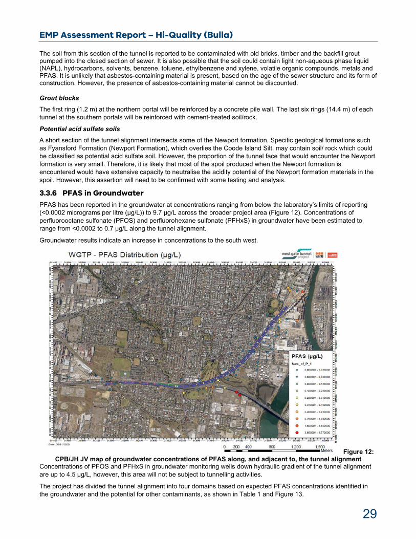
3.3.6 PFAS in Groundwater
PFAS has been reported in the groundwater at concentrations ranging from below the laboratory’s limits of reporting (<0.0002 micrograms per litre (µg/L)) to 9.7 µg/L across the broader project area (Figure 12). Concentrations of perfluorooctane sulfonate (PFOS) and perfluorohexane sulfonate (PFHxS) in groundwater have been estimated to range from <0.0002 to 0.7 µg/L along the tunnel alignment.
Groundwater results indicate an increase in concentrations to the south west.
Figure 12: CPB/JH JV map of groundwater concentrations of PFAS along, and adjacent to, the tunnel alignment
Concentrations of PFOS and PFHxS in groundwater monitoring wells down hydraulic gradient of the tunnel alignment are up to 4.5 µg/L, however, this area will not be subject to tunnelling activities.
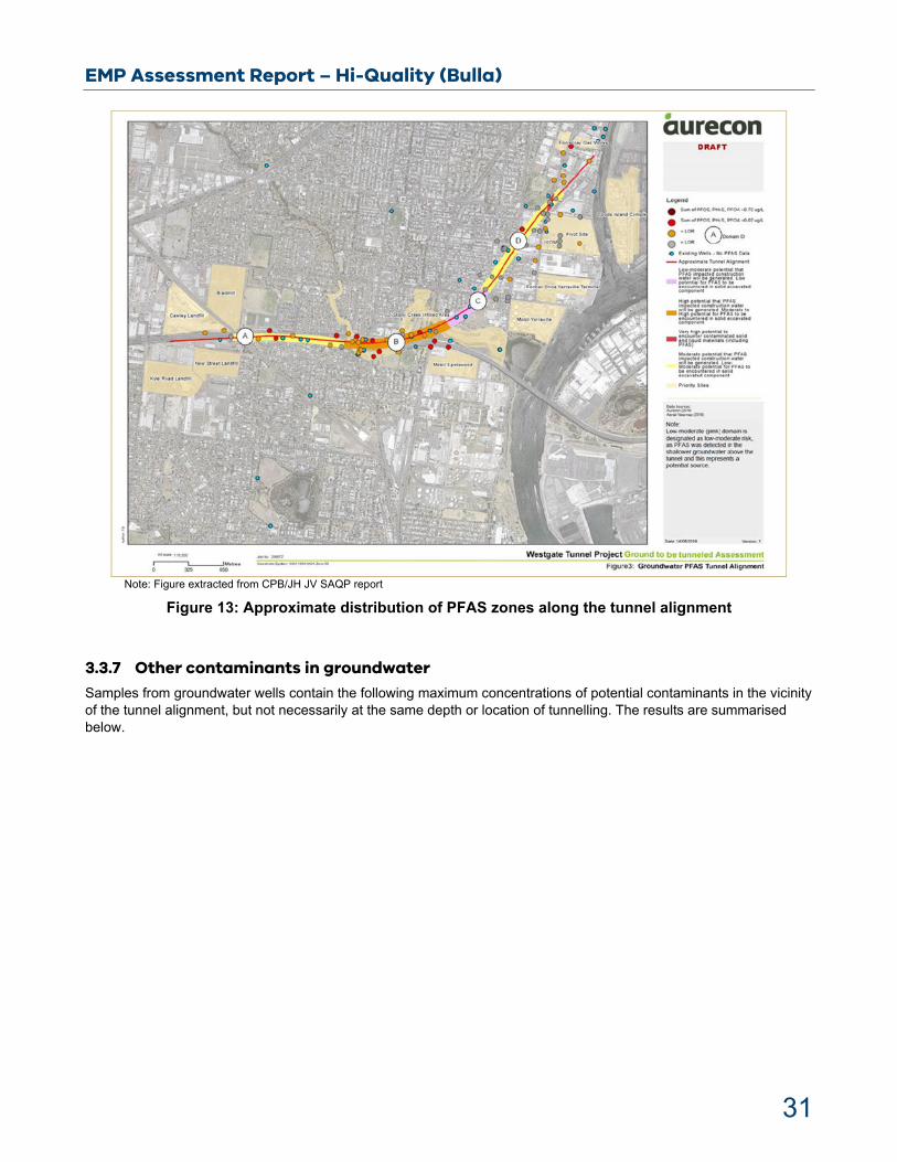
The project has divided the tunnel alignment into four domains based on expected PFAS concentrations identified in the groundwater and the potential for other contaminants, as shown in Table 1 and Figure 13.

EMP Assessment Report – Hi-Quality (Bulla)
30
Soil samples collected along the tunnel alignment at the depth of excavation were not analysed for PFAS compounds.
Table 1: Summary of volume of spoil in relation to each PFAS classification zone
Note: Table extracted from CPB/JH JV SAQP report
EMP Assessment Report – Hi-Quality (Bulla)
31
Note: Figure extracted from CPB/JH JV SAQP report
Figure 13: Approximate distribution of PFAS zones along the tunnel alignment
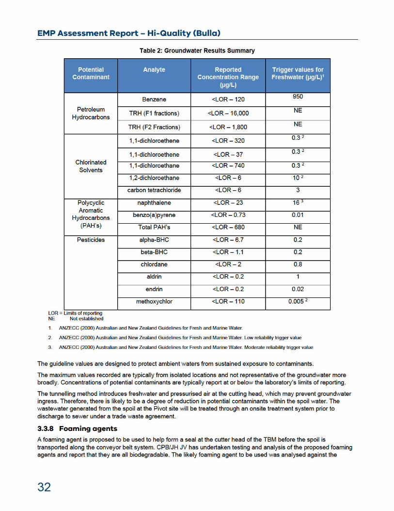
3.3.7 Other contaminants in groundwater
Samples from groundwater wells contain the following maximum concentrations of potential contaminants in the vicinity of the tunnel alignment, but not necessarily at the same depth or location of tunnelling. The results are summarised below.

EMP Assessment Report – Hi-Quality (Bulla)
33
Australian and New Zealand Environment Conservation Council (ANZECC 2000) water quality guidelines for 95 per cent species protection. Concentrations were reported below the laboratory’s limits of reporting for the chemicals listed.
EMP Assessment Report – Hi-Quality (Bulla)
34
4 Hi-Quality Environment Management Plan
4.1 Spoil management proposal
The WGTP TBM is anticipated to generate an average of 5,900 m3/day (8,400 tonnes/day), with a peak operation period which will produce approximately 7,600 m3/day (11,000 tonne/day). Peak truck movements of spoil are expected to be up to 360 trucks per day (15 per hour).
The spoil will be delivered from the TBM onto its conveyor for transport to a purpose-built soil handling facility located at the former Pivot site, at Whitehall St, Yarraville. From the Pivot site the soil will be loaded into trucks and potentially taken to the Hi-Quality site where they propose to store and categorise the spoil at its site located at 570 Sunbury Road, Bulla VIC 3428 (the Site).
Categorised spoil will either be deposited in a containment cell at the Site or be transported for either treatment or disposal at an appropriate facility.
4.2 Spoil storage
From the Pivot site the spoil will be loaded into trucks and transported to the Site into holding bays where it will be sampled for categorisation. The volume held in each bay is expected to not exceed 10,000 m3. Some draining and drying will have occurred since the spoil was produced by the TBM. There will be one set of bays for each tunnel.
At the Site, spoil will be stored in bays for up to 21 days while awaiting categorisation for containment on-site or disposal. During this period the spoil will release water and partially dry.
4.3 Soil sampling regime
4.3.1 Sampling at the source
In a 24-hour period, there will be six occasions when excavators pause, and soil can be sampled at the Pivot site. At this time, their buckets can be lowered onto the ground and made accessible for safe sampling. This will provide per tunnel a minimum of 12 primary samples plus 2 or 3 duplicate and 2 or 3 triplicate samples. Average daily production is 5,800 to 7,600 loose cubic metres (LCM). This equates to 1 sample per 240 LCM for average production and 1 per 315 LCM for peak production rates.
For anomalous spoil or spoil from exception zones that needs to attain the 1 sample per 250 m3 sampling rate using primary samples no additional samples are required at average production rates and 3 additional samples are required at peak production rates.
Sampling must be undertaken by suitably qualified consultants appointed by the duty holder.
4.3.2 Sampling at Hi-Quality
Soil volumes greater than 2,500 m3 require sampling at a density of one sample per 250 m3. For homogeneous material, the SAQP indicates that sampling at that rate may not be required.
Consistent with IWRG702, the SAQP preferentially employs the 95 per cent upper confidence interval plus arithmetic level mean concentration (contracted to ‘95 per cent% upper confidence limit (UCL)average’ or ‘UCL95’, where UCL represents upper confidence limit) as a measure of central tendency in chemical test data comparison with the soil acceptance criteria or waste categorisation criteria.
The field pH will be compared with EPA Publication 655.1 – Acid Sulfate Soil and Rock.
4.3.3 Spoil from exception zones There are three exception zones. Spoil derived from these zones requires specific sampling and analysis, once received at the proposed holding bays.
Exception zone 1: Potential contaminants from the former North Yarra Main Sewer.
Exception zone 2: Cement grout from the portal grout blocks.
Exception zone 3: Potential ASS from the Fyansford Formation (in Domains 7 and 8).

EMP Assessment Report – Hi-Quality (Bulla)
35
Anomalous spoil will be segregated and managed separately. The anomalous spoil will initially be assessed to determine if the material requires further processing or treatment to enable disposal at Hi- Quality Landfill or alternatively disposal off-site to a suitably licensed facility.
Potential acid sulfate soils (PASS) will be sampled and assessed to determine if the soil has the potential be waste acid sulfate soils (WASS). If WASS is indicated, then it will be managed by application of lime. WASS or PASS will be spread in 250-mm lifts with lime applied at the rate required to neutralise any acid generation.
The sampling methodology and the rational for minimum sample rate are to be determined.
EPA conclusions
The SAQP proposes to derive the duplicate and triplicate quality control samples from primary samples. This means that one sample would be converted into three samples for comparability.
The total and leachable concentrations of PFAS will be measured in samples of spoil taken from the holding bays. The concentrations of PFAS in water that drains from the spoil may differ significantly from those in in situ groundwater or in the water in the spoil immediately after production in the TBM.
Overall, the total mass of dissolved and adsorbed PFAS per unit bulk volume of spoil and spoil water placed in the holding bay should be lower than that in the produced spoil, due to the drainage that would have occurred.
4.3.4 Spoil analysis Spoil from the identified zone of exception or that has spoil with visual/odour indicators of contamination observed during loading or delivery will require analysis for IWRG 621 full screen suite.
Spoil from other domains will be analysed for total and leachable concentrations of all PFAS analytes, referred to as PFOS, PFHxS and PFOA.
The reference procedure is in AS 4439.3 – 1997, with US EPA Method EPA- 821-R-11-007 for the solid component and US EPA 537 for the liquid component.
To provide greater confidence in the reproducibility of results, blind replicates, split samples and rinsate blanks should be collected at a rate of at least one for every ten primary samples.
Appropriate numbers of quality control (QC) samples as outlined in Table 4 of AS 4482.1-2005 (Guide to the investigation and sampling of sites with potentially contaminated soil. Part 1: Non-volatile and semi-volatile compounds) are required to be taken from the site of origin.
4.3.5 PFAS testing regime The total and leachable concentrations of PFAS will be measured in samples of spoil taken from the holding bays. The concentrations of PFAS in water that drains from the spoil may differ significantly from those in situ groundwater or in the water in the spoil immediately after production in the TBM.
Overall, the total mass of dissolved and adsorbed PFAS per unit bulk volume of spoil and spoil water placed in the holding bay should be lower than that in the produced spoil, due to the drainage that would have occurred.
PFOS/PFHxS and PFOA testing will be undertaken using the method described in Table 16 of the SAQP.
Testing regime:
First 10 bays of spoil from each geological domain – all samples (plus QC samples) are to be tested.
If trends in the maximum data values from each of these 10 bays indicate that results are trending at <75 per cent of the soil acceptance criteria, then testing is reduced to two primary samples plus 2 duplicate and 2 triplicate samples per 2,500 to 3,500 m3 per bay (minimum testing regime).
Subsequently, as each next bay is filled, trends over the previous 10 bays will continue to be monitored.

EMP Assessment Report – Hi-Quality (Bulla)
36
4.3.6 Spoil water sampling locations and frequency Water derived from spoil will be sampled from the lowest point in each filled holding bay’s drainage system, between 7 and 14 days after filling.
EPA considered that the sampling and analysis approach taken by the project is appropriate. The statistical analysis approach presented is based on comparing the confidence intervals to waste thresholds.
All samples will be analysed as per chain of custody documentation.
EPA conclusions
EPA is satisfied that the proposed spoil management methods are in compliance with the relevant subordinate legislation and the guidelines.
4.3.7 Assumptions The waste categorisation will be based on what was measured in the samples taken from the spoil when placed in the holding bay. The true leachable concentrations are likely to be lower than these values.
It is assumed that that the maximum PFAS concentrations in the tunnel spoil are likely to be less than those in the groundwater. At such concentration, PFAS contained in spoil does not pose an unreasonable risk to the environment when contained as per the proposed method.
By the time spoil is placed in the containment cell, the total and leachable concentrations may have changed from what were measured in the samples taken from the spoil when placed in the holding bay.
The tunnel is unlikely to be contaminated with anthropogenic contaminants other than PFAS. The exceptions to this are spoil from Domain 1, 2 and 3. Therefore, the containment or disposal of spoil from other domains may be determined by its total and leachable PFAS concentrations.
4.4 Spoil deposition
Following, and depending on, the final spoil categorisation results, spoil may be deposited into a containment cell at the Site. For the purposes of assessment, this containment cell has been compared to and considered in accordance with EPA Publication 788.3 (Siting, design, operation and rehabilitation of landfills).
4.4.1 PFAS Thresholdsfor containment cell All other waste management options have been evaluated before off-site containment of low level PFAS contaminated spoil was considered. In determining whether a landfill will be suitable to accept solid PFAS-contaminated materials, considerations included:
containment cell siting considerations
performance of landfill liner and leachate management system
leachate management practices
treatment of PFAS containing materials prior to release, or reuse either on- or off-site.
These considerations are discussed further in section 5. The containment cell is to be lined and capped with a composite liner designed in accordance with a Type 2 landfill in EPA Publication 788.3. The assessment of the suitability of the containment cell is further discussed in section 7.2.
EPA consider that the threshold criteria for PFAS will be primarily based on a leachability criteria rather than total mass concentrations. This is due to the potential mobility of PFAS in the environment. The mobility of PFAS is related to how leachable it is compared with what the total mass may be in the soil. However, the total concentrations of PFOS + PFHxS and PFOA in spoil entering the cell will not exceed human health-based guidance values applicable to industrial/commercial land use application of spoil (for example, PFOS + PFHxS <20 mg/kg; PFOA <50 mg/kg).
A summary of Hi-Quality’s proposed site-specific trigger levels for PFAS for the containment cell and industrial waste is presented in Table 3. These were developed based on a risk assessment undertaken by Hi-Quality’s consultants. Hi-Quality’s consultant has undertaken POLLUTEv7 modelling to demonstrate that the proposed engineered liner for the


EMP Assessment Report – Hi-Quality (Bulla)
38
Should the North Yarra Main Sewer and the grout blocks material be identified as Category B or A PIW, material must only go to a facility licensed to receive such waste.
EPA conclusions
The categorisation and disposal management procedure as described is appropriate.
4.5 Spoil
EPA will use one of the following as the basis for assessing sampling procedures:
EPA’s Industrial Waste Resource Guidelines, 2009, Publication IWRG701 – Sampling and Analysis of Waters, Soils and Waste.
EPA’s Industrial Waste Resource Guidelines, 2009, Publication IWRG702 – Soil Sampling
Any other relevant methods or guidelines approved by EPA.
Average daily production per tunnel is approximately 5,900 m3, and peak average production is expected to be approximately 7,600 m3 in total across the two tunnels. A base level of sampling would occur at the Pivot site. In a 24-hour period there will be six occasions when excavators pause. Safe sampling would occur during this time. This will provide a minimum of 12 primary samples plus 2 or 3 duplicates and 2 or 3 triplicates. This equates to 1 sample per 180–240 LCM.
Hi-Quality’s proposed works will involve segregation and processing the spoil so that the appropriate management options can be decided (for example, reuse, containment or disposal in a licensed facility). As such, the proposed works will effectively reduce the material going to landfills for disposal.
The deposition of spoil material in the cell will occur in a series of progressive lifts to raise the level of the land, commensurate with the surrounding topography.
The SAQP document reference procedure for total PFAS concentration in soil is US EPA Method EPA-821-R-11-007.
4.6 Leachate
Water that drains from the spoil in the holding bays, and leachate that drains from the spoil when placed in the containment cell, will be directed to the leachate treatment pond. EPA considers that leachate criteria should be protective of groundwater and surface water quality and aquatic ecosystems at the site of containment, and protective of sensitive receptors and environmental values.
Detailed design drawings for storage of the spoil material and leachate in holding bays and pre-treatment leachate holding dams, respectively, have been prepared.
. The proposed ponds will consist of
Leachate collected in the containment cell sump will gravity drain to a holding tank and be pumped directly to a wastewater treatment plant.
The treatment process is expected to remove contaminants, including PFAS, to at least the drinking water standards.
.
The standing water level in the leachate collection sump (as progressively installed) will be controlled automatically.
The storage and handling of leachate and treated water within the facility must be in accordance with EPA Publication 1698 – Liquid Storage and Handling Guidelines. Uncovered areas, such as leachate drainage areas, will have a system to accommodate rainwater.
The treated water monitoring program is summarised in the EMP. Laboratory parameters include pH, dissolved oxygen, electrical conductivity, total suspended solids, PFOS, PFHxS and PFOA.

EMP Assessment Report – Hi-Quality (Bulla)
39
The frequency of leachate sampling is as per the monitoring program, as specified within the waste management plan.
4.7 Groundwater
On a regional scale, groundwater flow is inferred to be in a southerly direction towards Port Phillip Bay. At the site scale, the pre-landfilling groundwater flow direction is inferred to be in an east-south-easterly direction from the ridge lines to Emu Creek.
The Site’s groundwater has been conservatively classified as being within Segment B, precluding potable beneficial use.
The groundwater bores (as shown in the EMP) will be monitored for standing water level and sampled for field and laboratory analysis. Groundwater will be tested biannually. Baseline monitoring will include pH, dissolved oxygen, total dissolved solids, total suspended solids, PFOS, PFHxS and PFOA.
Standing water levels are to be measured in all groundwater monitoring wells and recorded on the same day during any sampling rounds.
EPA conclusions
Regional hydrology and the groundwater flow regime are understood by the duty holder. The placement of PFAS-impacted spoil and wastewater is considered to be appropriately controlled, and hence, the potential impacts on groundwater and surface water are mitigated.
4.8 Surface water
Surface water generated from the Site is to be monitored. The Site generally slopes in a north-north-easterly direction. The topography is gently undulating on the western part of the Site and is deeply incised in the north and east where Emu Creek has eroded into the basalts and underlying bedrock.
Emu Creek joins Deep Creek approximately 1.4 km to the southeast of the Site. Deep Creek is a larger watercourse of the Port Phillip catchment, and may offer limited fishing opportunities to the south at the Bulla Crossing, approximately 2 km south of the confluence with Emu Creek. Deep Creek reaches its confluence with the Jackson Creek near Bulla and together they form the Maribyrnong River.
As part of the Sunbury South Precinct Structure Plan, a future drainage channel is proposed to be constructed through Hi-Quality’s site to manage 1-in-100-year rainfall events. Design and construction work on the 1-in-100-year drainage channel will occur after the proposed containment cell reaches final capacity and is completed. The final design of the drainage channel will have to consider the containment cell infrastructure.
Assessment criteria for monitoring of Emu Creek and the are provided in the EMP.
The frequency of groundwater and surface water sampling is specified within the most recent landfill monitoring program reviewed by an auditor and included in the EMP.
EPA conclusions
EPA considers that human health risks are minimal because of the proposed surface water infiltration controls. The proposed controls would substantially mitigate off-site migration of contaminants to sensitive receptors.

EMP Assessment Report – Hi-Quality (Bulla)
42
proposed facility are described as being 360 m west (residential dwelling, excluding the Daameeli homestead on the Site) and 2.2 km to the northwest (residential area). EPA notes there is a property approximately 220 m to the south west of the site boundary. These distances are greater than the minimum listed for buildings and structures for solid inert landfills, but within that for putrescible landfills in EPA Publication 788.3 (not including on-site buildings and structures). It is likely that the recommended buffer distance for putrescible landfill is primarily related to issues with putrescible waste such as landfill gas, litter and odour which are not of concern with TBM spoil. The Site is located to the northwest of Melbourne Airport; at approximately 4.5 km to the airport Site boundary, it is in excess of the minimum distance for landfills in EPA Publication 788.3.
The distance from the containment cell and holding bay areas to the nearest surface water body (not including on-site surface water), Emu Creek, is greater than the minimum buffer distances for landfills specified in EPA Publication 788.3 (100 m to surface water) and the distance proposed in the NEMP for spoil reuse (200 m). All of the infrastructure is within the buffer distance to surface water discussed for landfills receiving PFAS waste in NEMP (1000 m). A reliance will therefore be placed on the leachate and surface water controls and subsurface to prevent this exposure pathway being open.
Table 4: Description of the land use surrounding the proposed receiving site (Table 3 of the EMP)
5.2 Topography and surface waters
The Site topography is detailed in the report. The Site generally slopes in a north/north-easterly direction. The topography is gently undulating on the western part of the Site and is deeply incised in the north and east where Emu Creek has eroded into the basalts and underlying bedrock.
Emu Creek is a small ephemeral feature to the immediate east of the Site. Emu Creek joins Deep Creek approximately 1.4 km to the southeast of the Site.
Deep Creek is a tributary of the Maribyrnong River, which it joins approximately 7 km south of the Site.
As per ADE Consulting (2018):
The Site is located on the Victorian Volcanic Plains, a landscape dominated by Cainozoic volcanic deposits, and this is noticeable through the rocky outcrops and rock escarpments at the Site. The Site is comprised of a large area of relatively flat land, extending approximately 500 m setback into the Site from Sunbury Road. The Site’s general topography drains toward Emu Creek and there are a number of incised gullies and drainage corridors on the land.
The holding bay area and associated infrastructure are proposed to be located in a relatively flat topographic high in the southeast corner of the Site. The containment cell is proposed to be located over an incised gulley drainage feature and into an area of current surface operations. This placement in the gulley feature needs to be carefully considered to prevent surface water ingression causing potential leachate, stability and erosion issues. Infilling of valleys with landfill

EMP Assessment Report – Hi-Quality (Bulla)
43
cells (which have similar engineering features to the containment cell) is discouraged in EPA Publication 788.3, with the following additional considerations provided if infilling of a valley is otherwise desirable:
Furthermore, because a valley fill landfill is located in a drainage line, extensive management is required to control surface run-off water ingress into the landfill, potential planes of geotechnical weakness from leachate flows within the landfill, and leachate seeping from the landfill. This type of landfill should be limited to select solid inert wastes that are part of an engineered solution for an erosion problem.
The detailed designs include considerations of surface water drainage for the containment cells, to divert stormwater around the cells to the existing stormwater management system (section 7.2.1.6). Although not detailed these provisions do appear to be adequate to address stormwater management in this area. The designs also include provisions for further geotechnical investigations to ensure the cell meets stability and settlement objectives (section 7.2.1.2).
The gulley fill is proposed to facilitate the construction of a 1-in-100-year storm event drainage channel. This drainage channel is proposed to flow north to south along the western batter of the containment cell, flowing to join Emu Creek to the northwest of the Site. The exact path of this drainage channel is not provided and will need to be appropriately engineered so as not to provide water that may generate leachate or provide a pathway for PFAS from the containment area.
The proposed infrastructure does not appear to be included in areas prone to flooding. For example, it is not included in the floodway overlay of the VicPlan planning mapping tool. However, as noted above, the containment area is proposed to be located in a drainage feature and the potential for localised flooding and flow of stormwater through the area needs to be adequately addressed.
EPA conclusions
Infrastructure for, and management of, surface water drainage has been considered for the containment cell and the wider site. This is especially relevant to the containment cell due to its location in a drainage gulley feature. Stormwater is proposed to be directed away from any areas of spoil to prevent the generation of leachate and captured by the leachate management infrastructure.
5.3 Geology
The Site geology is described in the EMP, starting from the youngest:
Alluvial sediments: Alluvial or swamp deposits along Emu Creek bank and low-lying depressions (unconsolidated Quaternary deposits consisting of sand, sandy silt, silt and clay)
Newer Volcanics: Quaternary aged basalts outcrop across much of the Site and are exposed on the quarry walls, and consist of olivine basalt, scoria, thin interbedded sand, clay, and tuff.
Brighton Group: Logged as a 10 m thick interval in bores MB10A and MB10B, which are near the mapped Brighton Group outcrop in the northeast of the Site (Geological Survey of Victoria (GSV) Sunbury Map Sheet 7822 Zone 55 (1:63, 360)). Tertiary aged and generally consists of gravel, sand, silt and clay. The clayey sands pinch and swell between the basalt flows of the Newer and Older Volcanics.
Older Volcanics: Exposed in the quarries where they overlie the Werribee Formation. They outcrop in Emu Creek near the central eastern boundary of the Site and consist of tertiary-aged highly weathered olivine basalt.
Werribee Formation: Tertiary age sandy to gravelly sediment that is exposed below the Older Volcanic in the Site quarries.
Ordovician: Siltstone and sandstone sediments that outcrop northeast of the Site along Emu Creek, the western part of the Site, and at the base of the southern quarry pit.
The description of the geology of the Site does not indicate any underlying geology that may be unconducive to waste containment or highly erosional lithology, for example karst settings. The Site to the north is used for landfilling and has not encountered any problematic geology. The area does not appear to be seismically active and as per the

EMP Assessment Report – Hi-Quality (Bulla)
44
recommendation in EPA Publication 788.3 is over 100 m from a fault line displaced in the Holocene period, with the nearest neotectonic feature passing through Sunbury to the northwest of the Site (https://earthquakes.ga.gov.au/).
5.4 Hydrogeology and groundwater
5.4.1 Hydrogeological setting On a regional scale, groundwater flow is inferred to be in a southerly direction towards Port Phillip Bay. At the site scale, the pre-landfilling groundwater flow direction is inferred to be in an east-south-easterly direction from the ridge lines to Emu Creek. At the local scale, the occurrence and movement of groundwater at the Site is not well defined given the multiple aquifers and the limited number of groundwater monitoring bores in each aquifer (Nolan 2019) but is expected to flow in the general direction of Emu Creek.
The potential groundwater flow velocities within the various aquifers beneath the Site does not appear to be discussed. Furthermore, the information required to estimate groundwater flow velocities does not appear to be presented. From literature values, and using hydraulic gradients presented in the hydrogeological assessment, groundwater flow velocities in the Older Volcanics and Werribee formation may average around 90 m/year. Velocities in the Silurian sediments may average approximately 8 m/year.
The depth to groundwater across the Site is not noted in the provided information. EPA has assessed potential depth to groundwater using Visualising Victoria’s Groundwater (VVG.org.au). The depth to groundwater is likely to range between 0 (for example. outcropping such as at the base of the quarry) and 50 m below the surface.
5.4.2 Background levels
Groundwater salinity within the Site is variable due to multiple aquifers intersected and their different proximity to recharge sources. Groundwater monitoring bores installed at the Site are screened within the Older Volcanics aquifer, Werribee Formation aquifer and Silurian bedrock aquifer. Based on the salinity range observed in the up-gradient monitoring bores, the Site’s groundwater has been conservatively classified as being within Segment B (1,201 to 3,100 mg/L), which does not include potable drinking water as a protected beneficial use. Additional up-gradient bores have reported salinity ranges classifying the groundwater unit within Segment C.
Existing levels of PFAS within the aquifer are presented and discussed in section 9 and Appendix J of the EMP. A network of 16 groundwater monitoring wells were sampled.
Four additional groundwater wells are proposed to be installed, surrounding the proposed spoil management area. These are scheduled to be sampled prior to receipt of spoil.
EPA conclusion
Existing groundwater concentrations for potential contaminants for the majority of the Site have been established. Further information and sampling results detailing background concentrations upgradient and near planned infrastructure following installation of new monitoring wells (prior to the receipt of spoil) will be provided to EPA as it is collected.
5.4.3 Beneficial uses Based on the groundwater segment (Segment B), protected beneficial uses for the area include:
water dependent ecosystems and species
agricultural and irrigation (irrigation)
agriculture and irrigation (stock watering)
water-based recreation (primary contact recreation)
industrial and commercial.
EMP Assessment Report – Hi-Quality (Bulla)
45
potable mineral water supply
traditional Owner cultural values
cultural and spiritual values
buildings and structures
geothermal properties.
In terms of the key PFAS in question this equates to maximum values consistent with the Australian Drinking Water Guideline (ADWG) values of 0.07 µg/L PFOS+PFHxS and 0.56 µg/L PFOA.
Potable mineral water does not apply to the Site as groundwater is not mineral water as defined in SEPP (Waters). Geothermal properties do not apply as groundwater temperature is not within 30 to 70oC as specified in SEPP (Waters).
Extractive beneficial uses are considered to be existing in the area.
Six groundwater bores were identified within 1,000 m of the proposed containment area. Two wells are associated with domestic and stock at a minimum depth of 67 m. One well was designated for commercial purposes and the purposes of three wells were unknown.
EPA Publication 688 suggests a 2 km bore search radius. There are 28 groundwater bores within a 2,300 m radius of the centre of the containment area (giving an approximate 2,000 m radius from the boundaries of the containment area): 3 domestic and stock (drilled to 54, 67 and 90 m), 1 commercial (drilled to 5 m), 1 irrigation (drilled to 265 m), 15 investigation (drilled to between 27 and 83 m) and 8 unknown (drilled to between 17 and 150 m).
5.5 Background PFAS concentrations
Further information was supplied by the proponent (Appendix J of the EMP), which included PFAS monitoring data from the monitoring network at the Hi-Quality site for surface water and groundwater. The monitoring network is described in more detail in section 8.2 of this report. This data is temporally limited, representing one sampling point for most of the locations.
Emu Creek was sampled at the four sampling points detailed in Figure 23 (EC01 to EC04). The three upstream samples (EC01 to EC03) contained PFAS and PFOS above the Australia and New Zealand Guidelines (ANZG) for Fresh and Marine Water Quality 99 per cent species protection (0.00023 µg/L), but lower than the ANZG 95 per cent species protection (0.13 µg/L). All values for these three sample locations were below the ADWG value for PFOS+PFHxS and PFOA. The furthest downstream sample (EC04) had higher concentrations of PFAS, with PFOS+PFHxS at 0.085 µg/L and therefore over the ADWG of 0.07 µg/L, with PFHxS the dominant PFAS compound detected. The quarry sump was also sampled and analysed, with low levels of various PFAS detected and PFOS reporting above the ANZG 99 per cent species protection (0.00023 µg/L), but below the ANZG 95 per cent% species protection (0.13 µg/L).
Groundwater samples were analysed from boreholes MB2 (screened in Emu Creek alluvium), MB4R (screened in Older Volcanics), MB11A&B (screened in Upper Ordovician Siltstone) and WS1 (screened in sub-basaltic tertiary sediments). See Figure 23 for sample locations. All these sampling locations are within the area of current activities at Hi-Quality, with MB2 likely representing a downgradient location. The sample from MB2 contained the highest PFAS concentration with PFOS+PFHxS in excess of the ADWG at 0.34 µg/L. Individually, PFOS was above the ANZG 99 per cent species protection (0.00023 µg/L), but below the ANZG 95 per cent species protection (0.13 µg/L). The other groundwater samples from the Older Volcanics and tertiary sediments (WS1) contained low levels of PFAS, with PFOS above the ANZG 99 per cent species protection (0.00023 µg/L), but below the ANZG 95 per cent species protection (0.13 µg/L). The samples from the Upper Ordovician Siltstone (MB11A&B) contained very low levels, with only one detection of PFAS, for the precursor 6:2 fluorotelomer sulfonate.
EMP Assessment Report – Hi-Quality (Bulla)
46
6 Environmental and Human Health Risk assessment
6.1 Human health risk assessment
The Human Health and Ecological Risk Assessment (HHERA) has identified relevant exposure scenarios for on-site and off-site sensitive receptors to PFAS-contaminated soil, dust and water. EPA has reviewed the exposure scenarios relevant to human health in the following sections.
6.1.1 Operational use – on-site
Direct contact with spoil or inhalation of dust.
Direct contact with leachate or treated leachate
Both exposure pathways are relevant to Hi-Quality personnel and contractors and it was considered that a complete source pathway receptor (SPR) linkage existed.
EPA conclusions
These exposure pathways were considered further in the HHERA and incidental ingestion of leachate and dust formed the basis of deriving the site-specific trigger levels for PFSAs and PFCAs.
The assumptions used in the derivation of the site-specific trigger levels are suitably conservative.
6.1.1.1 Direct contact with leachate or treated leachate (transient ecological receptors)
Bioaccumulation is not anticipated within these engineered receptors.
EPA conclusion
The HHERA appears to consider the health of the ecological receptors such as water birds. The proponent has clarified that wildfowl is not resident for a period on the leachate pond. There are no other animals that are reported to rely on the leachate pond.
6.1.2 Off-site
6.1.2.1 Direct contact with soils where airborne dust has deposited or inhalation of dust
(residents)
The HHERA assumes that dust will be managed on-site with engineering controls and/or dust mitigation measures ensuring that significant off-site migration of dust does not occur. The HHERA therefore assesses that this SPR linkage is not complete.
EPA conclusions
Once operational, EPA will receive further information on monitoring of the effectiveness of controls at preventing substantial migration of dust off-site as part of the EMP to ensure this SPR linkage remains incomplete.
EMP Assessment Report – Hi-Quality (Bulla)
47
Contingency plans (which include trigger values for erosion and off-site soil impacts) are in place to respond to incidents (control dust, assess risk and remediate where necessary) involving significant movements of dust off-site should they occur.
6.1.2.2 Direct contact with surface water (recreational users)
The HHERA assumes that engineering controls will manage surface water on-site to the extent that there will be no potential for off-site migration of PFAS via surface water. The HHERA assesses this SPR linkage as incomplete. Details on the segregation and management of leachate within containment are provided in sections 6.7, 7.2, and 7.3.
EPA conclusions
Monitoring of the effectiveness of controls in preventing migration of PFAS off-site via surface water has been included in the EMP to ensure this SPR linkage remains incomplete. This is discussed in section 8 below.
Contingency plans (which include trigger values for surface water run-off) must be in place as described in the EMP, to respond to incidents (contain surface water runoff, assess risk and remediate where necessary) involving significant off-site surface water run-off if it occurs. An assessment of the monitoring plan provided in the EMP application is provided in section 8.
6.1.2.3 Direct contact with, or irrigation using, groundwater (residents)
The HHERA assumes that engineering controls will preclude PFAS impacts to groundwater as a result of leaching from the containment area. It states that due to depth of groundwater and the non-potable use of groundwater, water from the aquifer beneath the Site will not represent a PFAS source to off-site residents. The HHERA assesses this SPR linkage as incomplete.
EPA conclusions
The assumption in the HHERA that there will be no PFAS impacts to groundwater as a result of leaching from the containment area is based on liner performance modelling.
The HHERA states that the modelling confirms that a lining system of will be effective in
containing material with higher than expected PFAS concentrations to within Australian drinking water criteria.
Monitoring of the effectiveness of the liner performance in the containment area in EMP is proposed to be undertaken to ensure the SPR linkages remain incomplete.
Contingency plans (which include trigger values for impacts to groundwater) must be in place as described in the EMP to respond to incidents (assess risk and remediate where necessary) involving significant groundwater impacts if they occur. An assessment of the monitoring plan provided in the EMP application is provided in section 8.

EMP Assessment Report – Hi-Quality (Bulla)
48
6.1.2.4 Groundwater abstraction for stock watering (livestock health)
The HHERA assesses this pathway against livestock health as the receptor. It assumes an incomplete SPR linkage based on liner performance modelling.
EPA conclusions
Refer to conclusions in section 6.4.4 in relation to the liner performance modelling.
Contingency planning (which includes trigger values for groundwater) for responding to incidents involving significant impacts to groundwater also considers the need to assess risks to humans who may consume impacted livestock.
6.1.2.5 Consumption of fin fish
The HHERA assumes that engineering controls will contain PFAS-affected media (dust, surface water, groundwater) on-site. The HHERA assesses this SPR linkage to be incomplete.
EPA conclusions
Monitoring of the effectiveness of controls in preventing substantial migration of dust, surface water and groundwater off-site is proposed in the EMP to ensure this SPR linkage remains incomplete.
Contingency plans (with trigger values for surface water run-off, erosion and off-site migration of soils and impacts to groundwater) must be in place as described, to respond to incidents (control off-site migration of PFAS-contaminated media, assess risk and remediate where necessary) involving significant movements of dust, surface water and PFAS-contaminated groundwater off-site if they occur.
6.1.3 Future use
On-site
Direct contact with spoil in containment area (Intrusive maintenance workers)
Direct contact with leachate in the containment area (Intrusive maintenance workers)
EPA conclusions
The HHERA determines this SPR linkage to be incomplete as exposure to spoil and leachate will not occur due to the area being capped in accordance with EPA Publication 788.3. This is a reasonable assumption.
6.2 Ecological risk assessment
Due to the use of the Site as a landfill and quarry and the lack of significant groundcover, permanent terrestrial receptors at the Site are not included in the HHERA. Evidence is not provided for the potential impact on the permanent terrestrial ecology of the Site for this assessment. In terms of modified habitat, this needs to be adequately addressed during the rehabilitation of the Site. Transient on-site ecological receptors are considered in the form of birds that may use the surface water features such as the leachate ponds. An assessment was made for ingestion of leachate contained in the on-site storage ponds by the waterfowl.
The HHERA report notes that the surrounding area is significantly cleared and the ecology likely a highly modified habitat. The report addresses the following sensitive ecological receptors off-site:

EMP Assessment Report – Hi-Quality (Bulla)
49
The Environment Protection and Biodiversity Conservation Act 1999 (Cth) (EPBC Act) Protected Matters Search Tool (PMST) was consulted on 2 December 2019. Four threatened ecological communities, 26 threatened species, and 14 migratory species were identified as potentially present within 1 km of the Site. Of these, one threatened ecological community and two threatened species are known to occur within 1 km of the Site.
These off-site receptors are not considered as part of the HHERA, as it is proposed the key pathways will prevent off-site migration of PFAS. This is contingent on the successful implementation of engineering and management controls of exposure pathways. The treated leachate will have up to
6.3 Hydrogeological risk assessment
6.3.1 Groundwater risk assessment – containment cell, holding bay area and leachate ponds
The application seeks to establish a site-specific risk-based criterion for the acceptance of waste to the containment cell. Therefore, the NEMP landfill acceptance criteria are not requested to be used along with the corresponding engineering (for example, composite lined or double composite lined).
Modelling is provided of PFAS transport from the spoil in the holding bays and containment cell or the leachate in the leachate ponds, to groundwater across various liner profiles and site specifications. This is then used to inform the proposed liner configuration and the leachable fraction (as ASLP or leachate concentration) of contaminants that can be contained within the cell, holding bays or leachate pond, without precluding the relevant beneficial use in the groundwater.
The application uses the POLLUTEv7 software, which is a widely used program for understanding the fate and transport of contaminants across landfill liner components.
A deterministic approach was used for the various input parameters. These are informed by either literature references, communication with experts or site-specific specifications informed by previous work characterising the Site. To understand the impact of uncertainty, sensitivity analysis was performed on selected parameters. This approach is broadly in-line with guidance such as EPA Publication 688 and the Australian Groundwater Modelling Guidelines (Commonwealth of Australia 2012).
The proposed conceptual model for the groundwater risk assessment considers the transport of PFAS across the liner and underlying subsurface (via advection and diffusion), in addition to the initial dilution in the receiving aquifer. Retardation in the form of adsorption to the solid phase is considered through each layer of the profile, while degradation is not considered due to the recalcitrant nature of PFAS. The receiving aquifer underneath the source zone (containment cell, leachate pond or holding bay area) is assumed to be the point at which the beneficial use is realised (and cannot be exceeded) – that is, no lateral transport downgradient within the aquifer is considered (no attenuation zone). The selection of this point for considering the beneficial use of the groundwater is consistent with SEPP (Waters) 2018 and the approach detailed in EPA Publication 788.3.
The relevant beneficial uses of the groundwater at the Site are discussed above. The ADWG criteria values of 0.07 µg/L PFOS+PFHxS and 0.56 µg/L PFOA are adopted to assess potential risk to beneficial uses of the aquifer. This approach is inconsistent with SEPP (Waters), which indicates that where natural background levels are better than environmental objectives, the background levels become the objectives (the natural background level of PFAS is below the detection limit). However, it should also be noted that the proposed liner is in excess of a Type 2 liner for a landfill, as per EPA Publication 788.3 and therefore, assuming suitable construction procedures are adhered to (assessed under the construction audit), approaches best practice in containment for landfills and would form the basis of “minimising risks to the extent practicable” in accordance with SEPP (Waters). The requested acceptance criteria are also not at the maximum that the modelling indicates could be contained and therefore the concentration in the aquifer would be assumed to be lower than the guideline value.
The modelling approach sets out time intervals to report the concentration at various depths, which vary depending on the source considered. The reported concentrations at the time intervals for the receiving aquifer indicate whether the concentration of the guideline protective of the beneficial use is exceeded. The approach does not consider changes in management over time or changes in the integrity of the key liner components.
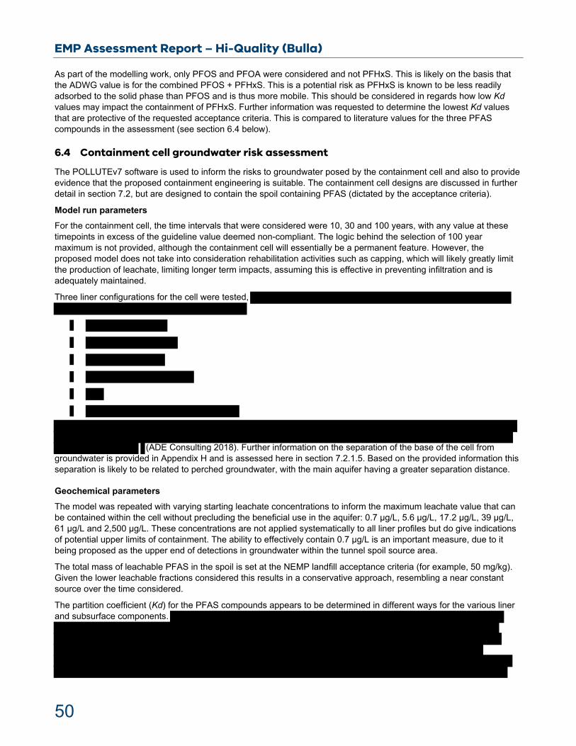
EMP Assessment Report – Hi-Quality (Bulla)
50
As part of the modelling work, only PFOS and PFOA were considered and not PFHxS. This is likely on the basis that the ADWG value is for the combined PFOS + PFHxS. This is a potential risk as PFHxS is known to be less readily adsorbed to the solid phase than PFOS and is thus more mobile. This should be considered in regards how low Kd values may impact the containment of PFHxS. Further information was requested to determine the lowest Kd values that are protective of the requested acceptance criteria. This is compared to literature values for the three PFAS compounds in the assessment (see section 6.4 below).
6.4 Containment cell groundwater risk assessment
The POLLUTEv7 software is used to inform the risks to groundwater posed by the containment cell and also to provide evidence that the proposed containment engineering is suitable. The containment cell designs are discussed in further detail in section 7.2, but are designed to contain the spoil containing PFAS (dictated by the acceptance criteria).
Model run parameters
For the containment cell, the time intervals that were considered were 10, 30 and 100 years, with any value at these timepoints in excess of the guideline value deemed non-compliant. The logic behind the selection of 100 year maximum is not provided, although the containment cell will essentially be a permanent feature. However, the proposed model does not take into consideration rehabilitation activities such as capping, which will likely greatly limit the production of leachate, limiting longer term impacts, assuming this is effective in preventing infiltration and is adequately maintained.
Three liner configurations for the cell were tested,
(ADE Consulting 2018). Further information on the separation of the base of the cell from groundwater is provided in Appendix H and is assessed here in section 7.2.1.5. Based on the provided information this separation is likely to be related to perched groundwater, with the main aquifer having a greater separation distance.
Geochemical parameters
The model was repeated with varying starting leachate concentrations to inform the maximum leachate value that can be contained within the cell without precluding the beneficial use in the aquifer: 0.7 µg/L, 5.6 µg/L, 17.2 µg/L, 39 µg/L, 61 µg/L and 2,500 µg/L. These concentrations are not applied systematically to all liner profiles but do give indications of potential upper limits of containment. The ability to effectively contain 0.7 µg/L is an important measure, due to it being proposed as the upper end of detections in groundwater within the tunnel spoil source area.
The total mass of leachable PFAS in the spoil is set at the NEMP landfill acceptance criteria (for example, 50 mg/kg). Given the lower leachable fractions considered this results in a conservative approach, resembling a near constant source over the time considered.
The partition coefficient (Kd) for the PFAS compounds appears to be determined in different ways for the various liner and subsurface components.
EMP Assessment Report – Hi-Quality (Bulla)
51
In assessment, although the relationship between foc and Koc is not well proven in the literature (Li et al., 2018) and the use of a Kd value based on observational data is advised (Anderson et al. 2018), the Kd values adopted for PFOS and PFOA are within the range of Kd values seen for soils in the literature (Li et al., 2018). Literature Kd values for PFAS adsorption to subsurface materials are highly variable and difficult to predict in comparison to other chemical compounds. Accurate prediction of expected Kd values for PFAS is inherently difficult; the values have associated uncertainty. To inform decisions on the presented modelling, the Kd values used in the EMP and those provided (on further request) as the minimum needed to meet the acceptance criteria, are compared to literature values. Li et al (2019) presented a review of Kd literature values for PFOS and PFOA for soils and sediments, with median values of:
PFOS = 83 L/Kg for field data and 16 L/Kg for laboratory data
PFOA = 14 L/Kg for field data and 2 L/Kg for laboratory data
The above values have a considerable range and are dependent on various physico-chemical parameters. Limited resources are available for PFHxS, with a median value of 1 L/Kg in soils reported in Guelfo and Higgins (2013). However, it is difficult to draw conclusions for PFHxS based on the limited studies available. The minimum Kd values protective of the proposed acceptance criteria for PFOS in the subsurface (2.1 L/Kg) are at the lower end of the range in Li et al (2019) for both field and laboratory data. This likely represents a conservative option for many subsurface materials. The PFOA Kd value for the subsurface (2.1 L/Kg) is at the lower end of the range for the field data, but above the median values for laboratory data. It is, therefore, potentially a less conservative value than for PFOS. As PFOA is not believed to be the PFAS driving risk in the spoil – risk-based guideline values are often higher for PFOA.
The majority of Kd values found in the literature are for soils or sediments and their relevance to other subsurface materials (for example, weathered rock materials) is unclear. Careful consideration is therefore required as to the ability of the subsurface to realise these Kd values. The Site is known to have unweathered basalts in addition to finer grained lithology of clays and silts. The potential for attenuation in unweathered basalts is limited, while likely greater for the finer grained weathered materials and clays/silts. The containment area is near boreholes MW1, MW2, MW3, MW4 and MB4R. To further subjectively constrain the potential for attenuation in the subsurface layer, borehole logs were consulted (ADE Consulting 2018) to inform the expected lithology:
MW1 – Bore depth of 57 m below ground level (bgl) with no groundwater encountered. Lithology encountered included basalts of varying weathering (Newer Volcanics), clays and sandy clays (Brighton group) and mudstones/siltstones.
MW2 - Groundwater encountered at 26 m bgl. The Older Volcanics basalt are highly weathered to a high plasticity clay, underlain by a weathered siltstone.
MW3 – Groundwater encountered at 6 m bgl. The lithology encountered was primarily composed of fill material of clay and silty clay, with some basalt fragments.
MW4 - Groundwater encountered at 18 m bgl. With surface layers of gravel and silty clay fill. The remainder of the depth is composed of high strength basalt and weathered basalt.
MB4R – Groundwater encountered at 40 m bgl. The surface material consists of highly weather basalts and silty clays (Newer Volcanics), followed by sandy clay (Brighton Group) and high strength basalts (Older Volcanics).
The above borehole information and details from the applicant indicate that the lithology encountered underneath the containment cell is likely variable. As a detailed subsurface model is not available for the containment cell area, only a subjective consideration can be provided. The borehole logs indicate that the subsurface under the containment cell could be expected to contain both unweathered volcanics and fine-grained materials. This variability will affect whether the proposed attenuation can be consistently realised (in terms of the Kd value). As a result, attenuation may be realised in some areas of the containment cell footprint, but not in other areas of the cell footprint. However, the model incorporates a 6 m separation from groundwater, and a relatively low Kd value, which indicates it may be protective of high values (330 µg/L PFOS or PFOA). Therefore, a degree of variability and uncertainty in the subsurface layer properties may be tolerable. This is, however, difficult to determine and should be considered alongside other conservatisms in the modelling.

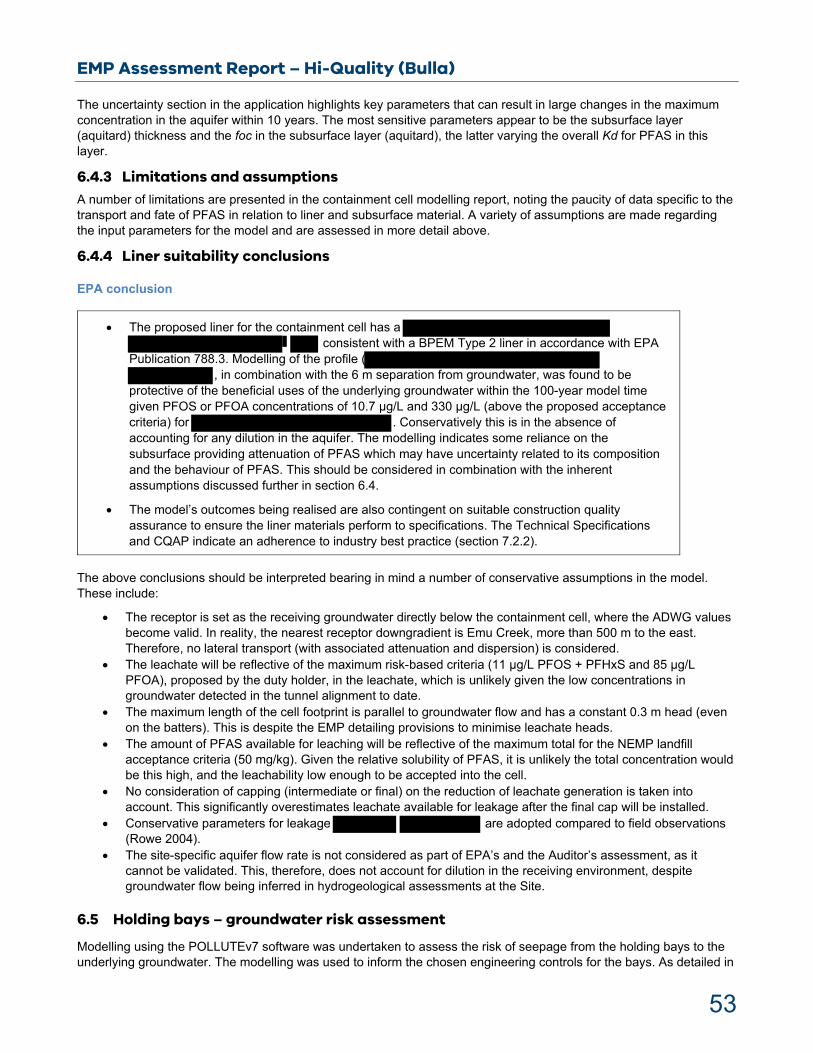
EMP Assessment Report – Hi-Quality (Bulla)
53
The uncertainty section in the application highlights key parameters that can result in large changes in the maximum concentration in the aquifer within 10 years. The most sensitive parameters appear to be the subsurface layer (aquitard) thickness and the foc in the subsurface layer (aquitard), the latter varying the overall Kd for PFAS in this layer.
6.4.3 Limitations and assumptions A number of limitations are presented in the containment cell modelling report, noting the paucity of data specific to the transport and fate of PFAS in relation to liner and subsurface material. A variety of assumptions are made regarding the input parameters for the model and are assessed in more detail above.
6.4.4 Liner suitability conclusions
EPA conclusion
The proposed liner for the containment cell has a consistent with a BPEM Type 2 liner in accordance with EPA
Publication 788.3. Modelling of the profile ( , in combination with the 6 m separation from groundwater, was found to be
protective of the beneficial uses of the underlying groundwater within the 100-year model time given PFOS or PFOA concentrations of 10.7 µg/L and 330 µg/L (above the proposed acceptance criteria) for . Conservatively this is in the absence of accounting for any dilution in the aquifer. The modelling indicates some reliance on the subsurface providing attenuation of PFAS which may have uncertainty related to its composition and the behaviour of PFAS. This should be considered in combination with the inherent assumptions discussed further in section 6.4.
The model’s outcomes being realised are also contingent on suitable construction quality assurance to ensure the liner materials perform to specifications. The Technical Specifications and CQAP indicate an adherence to industry best practice (section 7.2.2).
The above conclusions should be interpreted bearing in mind a number of conservative assumptions in the model. These include:
The receptor is set as the receiving groundwater directly below the containment cell, where the ADWG values become valid. In reality, the nearest receptor downgradient is Emu Creek, more than 500 m to the east. Therefore, no lateral transport (with associated attenuation and dispersion) is considered.
The leachate will be reflective of the maximum risk-based criteria (11 µg/L PFOS + PFHxS and 85 µg/L PFOA), proposed by the duty holder, in the leachate, which is unlikely given the low concentrations in groundwater detected in the tunnel alignment to date.
The maximum length of the cell footprint is parallel to groundwater flow and has a constant 0.3 m head (even on the batters). This is despite the EMP detailing provisions to minimise leachate heads.
The amount of PFAS available for leaching will be reflective of the maximum total for the NEMP landfill acceptance criteria (50 mg/kg). Given the relative solubility of PFAS, it is unlikely the total concentration would be this high, and the leachability low enough to be accepted into the cell.
No consideration of capping (intermediate or final) on the reduction of leachate generation is taken into account. This significantly overestimates leachate available for leakage after the final cap will be installed.
Conservative parameters for leakage are adopted compared to field observations (Rowe 2004).
The site-specific aquifer flow rate is not considered as part of EPA’s and the Auditor’s assessment, as it cannot be validated. This, therefore, does not account for dilution in the receiving environment, despite groundwater flow being inferred in hydrogeological assessments at the Site.
6.5 Holding bays – groundwater risk assessment
Modelling using the POLLUTEv7 software was undertaken to assess the risk of seepage from the holding bays to the underlying groundwater. The modelling was used to inform the chosen engineering controls for the bays. As detailed in
EMP Assessment Report – Hi-Quality (Bulla)
54
section 6.7, the holding bays are designed to allow drainage of leachate into swale drains that direct leachate to the leachate management system. However, it can be assumed that the potential for seepage will exist, as saturated spoil is present in the holding bays.
Input parameters
Section 3 of the holding bay modelling report notes that: ‘The model input parameters and methodology is consistent with that presented in the GHD report on Reuse Area POLLUTEv7 modelling (February 2020) undertaken to inform reuse containment cell area design.’ A number of parameters were modified to reflect the holding bay design:
Waste thickness: maximum considering a perimeter bund height of
Landfill length: bays in the direction of groundwater flow).
Aquitard thickness: 40 m (SMEC design details indicate the containment bays are at approximately natural surface level, the groundwater level is based off monitoring bore MW4 (ADE Consulting 2018).
Outflow velocity: results associated to the minimum default aquifer outflow velocity have been presented in this report.
Where unchanged from the containment area modelling and relevant here, parameters are not assessed further. However, where they have been changed or assumptions are changed, they are discussed further.
Modelling parameters
‘The estimated project duration is 18 months. The model was conservatively run for a period of 5, 7, 10 and 15 years to account for project delays and to consider possible ongoing use’. This approach is highly conservative as it assumes a constant PFAS source across the whole of the containment bay area continually for the above timeframes. These timeframes are far in excess of the expected project duration, which is also likely in excess of the period of use for an individual bay.
A variety of liner profiles were considered:
1.
The above profiles do not consider the overlying the containment layer which may further reduce infiltration to the underlying system.
Geochemical parameters
The modelled source leachate concentration was 0.7 µg/L, 5.6 µg/L, 11 µg/L, 85 µg/L and the higher value of 2500 µg/L.
As stated above, other geochemical parameters appear to have been adopted from the containment cell modelling report. These include the Kd values of the subsurface (aquitard), with no further consideration of potential differences in the lithology of this layer.
Engineering parameters

EMP Assessment Report – Hi-Quality (Bulla)
55
These parameters are principally adopted from the containment area modelling report and are relevant and justified here. It is assumed that the leachate head adopted is 0.3 m. Although no control is possible for this in the holding bays, it is assumed some of the material will be relatively free draining and given the slope of the bays will maintain a low hydraulic head. This is therefore likely a conservative approach.
Hydrological and hydrogeological parameters
These parameters are principally adopted from the containment area modelling report and are relevant and justified here. The aquifer flow velocity for the holding bay area modelling appears to have been conducted only for the minimal aquifer outflow velocity. This is a conservative approach which does not account for any dilution in the receiving groundwater.
Results
In absence of the 40 m subsurface, liner profiles 1 and 2 were ineffective in containing 0.7 µg/L PFOS/PFOA for the 15-year timespan but could retain PFOA for 10 years. This is under conditions which do not account for any dilution in the receiving aquifer or consider the substantial unsaturated zone and is thus likely a worst-case scenario. , profile 3 was ineffective in containing 0.7 µg/L PFOS for the 15-year timespan. Profile 4 effectively contained 0.7 µg/L PFOS/PFOA for the 15-year timespan but could only contain 5.6 µg/L PFOS for 5 years.
In the presence of the 40 m subsurface layer (aquitard) all profiles could contain PFOS and PFOA, up to concentrations of 2500 µg/L. From the depth profiles provided, the HHERA concentrations (11 µg/L PFOS and 85 µg/L PFOA), PFAS would penetrate to a depth of approximately 5 m by the end of the modelled period (15 years) in the absence of a geomembrane and considerably less in the presence of one.
Uncertainty analysis
No specific uncertainty analysis was presented in the holding bay area modelling report.
Limitations and assumptions
Few limitations and assumptions are discussed in the holding bay modelling report. However, many of the underlying assumptions and limitations in regards the selected parameters are discussed in detail in the containment cell modelling report.
EPA conclusion
The approach to modelling PFAS transport, in the hydrogeological risk assessment, across the liner of the holding bays is likely conservative as it does not consider provisions for surface drainage or the short timescale of the project. It also assumes a constant leachate head of PFAS-containing leachate across the whole of the holding bay area for the duration of the project. Given the intermittent use of bays this likely overestimates seepage.
The profile that is adopted in the holding bay design documents is is
considered protective of groundwater beneficial uses even with high PFAS concentrations and the assumptions outlined above.
In the absence of the 40 m subgrade, the model suggests that the chosen liner would not be protective of groundwater beneficial uses given a 5-year timeline. However, this is based on assumptions detailed above.
Even under the worst-case conditions modelled, penetration of PFAS was found to be unlikely to reach groundwater due to the substantial unsaturated zone in the area. The model indicates some penetration into this layer. However, as noted this is based on conservative assumptions which likely overestimate seepage and time available for seepage. It is interpreted that given the chosen liner and the holding bay design, seepage is likely to be low with little reliance on the subgrade.
EMP Assessment Report – Hi-Quality (Bulla)
56
6.6 Leachate pond – groundwater risk assessment
The leachate ponds are also subject to groundwater risk modelling using the POLLUTEv7 software. As above, this was used to inform the chosen engineering controls for the leachate ponds, which will receive leachate from the holding bay area and the containment cell prior to its treatment.
Input parameters
Section 3 notes ‘The model input parameters and methodology is consistent with that presented in the GHD report on Reuse Area POLLUTEv7 modelling (March 2020) undertaken to inform containment layer design’. A number of parameters were modified to reflect the leachate pond design:
Length of pond: 188 m (total pre-treatment pond length in the direction of groundwater flow).
Aquitard thickness: 40 m (SMEC design details indicate the containment bays are at approximately natural surface level, the groundwater level is based off monitoring bore MW3 (ADE Consulting 2018).
Leachate head on the primary liner: 1.5 m.
Modelling parameters
Although the project is anticipated to be in operation for 18 months, the model includes a constant PFAS source being present above the liner, with concentrations reported at 5, 7, 10 and 15 years. It is noted that the timeline for operation of the leachate ponds is unclear as it may receive leachate from the containment cell in excess of 15 years, depending on the amount of leachate produced in the containment cell post-capping. However, given the provisions for treatment of leachate the residence time of any PFAS in the ponds is likely to be low.
A variety of liner profiles were considered:
1.
The liner profile adopted in the designs included further provisions than those modelled, including a GCL (see section 7.3.1.3).
Geochemical parameters
The source of the PFAS in the leachate ponds is modelled as constant over the modelling period. The source concentration of the leachate modelled are 0.7 µg/L, 5.6 µg/L, 11 µg/L, 85 µg/L and 2500 µg/L.
As stated above, other geochemical parameters appear to have been adopted from the containment area modelling report. These include the Kd values of the subsurface (aquitard), with no further consideration of potential differences in the lithology of this layer. See the containment cell hydrogeological risk assessment section for more details.
Hydrological and hydrogeological parameters
The models were undertaken assuming the site-specific aquifer flow rate and with minimum outflow velocity (results in no dilution in the aquifer).
Results
All profiles were able to contain 2500 µg/L for the 15-year period, whether minimum outflow velocity or the site-specific groundwater velocity was chosen. Modelling was undertaken with the 40 m subsurface layer. For both profiles, at the HHERA concentrations, the PFAS had penetrated approximately 5 m into the underlying subsurface layer.
Uncertainty analysis
Sensitivity analysis was undertaken by removing the 40 m subsurface (aquitard) layer. As above, this highlights the dependence on the 40 m subsurface layer. Only liner profile 2 was found to be protective for PFOS and PFOA over the modelled timeline given a source concentration of 0.7 µg/L if site-specific aquifer flow rates were used. In the absence of the 40 m subsurface (aquitard) layer, no other liner profile variables were found to be protective.
Limitations and assumptions

EMP Assessment Report – Hi-Quality (Bulla)
57
The leachate pond modelling report discusses few limitations and assumptions. However, many of the underlying assumptions and limitations in regards the selected parameters are discussed in detail in the containment cell modelling report.
EPA conclusions
As with the holding bay area modelling, the model indicates some reliance on the properties of the 40 m subsurface layer (aquitard) being realised. However, the general approach to modelling parameters is likely to be conservative and EPA is satisfied that even if the aquitard is not as effective regarding attenuation the design would be sufficiently protective.
The EMP risk-based acceptance criteria for the leachate ponds is 250 µg/L, based on ecological protection values derived in the HHERA. This is significantly higher than the spoil leaching waste acceptance criteria and far in excess of the groundwater concentrations in the tunnel alignment to date. Such a high acceptance criterion for the leachate ponds may put a higher reliance on the 40 m subsurface layer properties being realised. Therefore, the EMP states that although higher concentrations could be contained within the ponds, a more conservative upper value is adopted: 7 μg/L for PFOS and 56 μg/L for PFAS. It is noted that this value is also in excess of the anticipated concentrations in the leachate but is sufficient to minimise potential impacts to groundwater.
6.7 Noise assessment
The proposed SWMF is to be located along the southern boundary of the existing Hi-Quality premises situated at 570-600 Sunbury Road, Bulla.
The noise assessment has identified 15 sensitive receptors surrounding the proposed SWMF, with the closest being southwest within urban growth zone (UGZ9), 170 m from the premises within the urban growth area of Bulla.
6.7.1 Noise modelling software
EPA considers it is the consultant’s responsibility to ensure that the noise modelling software used is fit for purpose, that is used adequately, and within the conditions for which it has been designed and validated.
The noise modelling software, Computer Aided Noise Abatement, used to model the proposed construction activities and the operational facility at Bulla is understood to implement adequately the procedures of ISO 9613-2 1996 (Acoustics – Attenuation of sound during propagation outdoors – Part 2: General method of calculation), which is a relevant standard for the calculation of environmental noise levels.
EPA understands the predicted noise impacts are conservative for the construction noise based on the worst-case scenario modelled whereby all equipment is operating simultaneously under atmospheric conditions favourable to the propagation of sound from the Site to the sensitive receivers.
6.7.2 Construction noise assessment While there are no statutory controls for noise from construction sites, all noise nuisances should be reduced wherever reasonably practicable from vehicles, fixed machinery within the Site, general construction activities, and from movements of vehicles servicing the Site.
The intent of both EPA Publications 1834 is that the first consideration is to minimise construction noise as far as reasonably practicable. This regard is to be made prior to considering compliance to specific noise levels.
Where EPA guidelines do not provide noise criteria, the most appropriate approach is to demonstrate application of requirements and measures implemented to reduce the impacts. EPA publication 1834 lists in section 2 provisions regarding community consultation, work scheduling, and work requirements which includes requirements and measures to be applied. Management of noise from construction activities should be about meeting these requirements in the first instance and then assessing the residual noise and addressing its impacts.
Further, EPA guidelines for construction noise have the default position that construction noise at night be inaudible within a habitable room of any residential premises during the hours of 10:00 pm to 07:00 am, Monday to Sunday.

EMP Assessment Report – Hi-Quality (Bulla)
58
There are exemptions to this requirement for works that are unavoidable – as defined in EPA publication 1834 – or approved managed impact works, but such exemptions need to be justified.
EPA notes that all construction activities are proposed to be undertaken during the day and evening, with no anticipated night works, other than receipt of waste spoils.
It should be noted that the background level to apply to define the noise criteria for weekend/evening and night period should represent the background at the time of impact.
Using the period-average background level determined for the purpose of SEPP N-1 is generally not appropriate as it is limited in reflecting the variations of the background across the considered period.
6.7.3 Sleep disturbance
While statutory policies and guidelines do not specifically define short term criteria (for example, LAmax) for sleep disturbance, we note that applying criteria from the NSW Noise Policy for Industry (NSW EPA 2017) is proposed.
We note that the noise assessment has identified impacts at the residential receivers during the operational night period, with levels below the screening criteria in NSW Noise Policy for Industry, 2017.
6.7.4 Heavy vehicle noise
Road traffic noise
EPA understands that the operations of the spoil processing and management facility at peak periods will increase the road traffic on surrounding roads by 36 heavy vehicle movements per hour (18 vehicle movements in each direction) with typical operations involving 26 heavy vehicles movements per hour (13 vehicle movements in each direction) across all periods (day, evening and night) for weekdays and weekends.
The noise assessment states that the “operational traffic noise levels are predicted to increase by up to 3 dB at the assessed receiver locations” and have been deemed “just perceptible to the majority of people”.
These considerations are made considering LAeq levels averaged across the whole day (07:00 am to 10:00 pm) or night (10:00 pm to 07:00 am) period. However, this index is limited in its ability to reflect the increase in the number and frequency of loud events from passing trucks that can have a significant impact.
Given the anticipated increase in heavy vehicle movements particularly during the night, there is the potential that the number of events that can cause awakenings will also increase. The closest sensitive receiver may get additional noise from the engine braking, and/or trucks turning into and out of the premises.
An assessment based on the number, frequency and magnitude of loud events (using a short-term noise indicator such as LAmax) would give a better representation of these impacts.
The acoustic report discusses measures that can assist in reducing potential impact:
“avoid the use of engine compression brakes.
Advocate appropriate driver behaviour.
Keep truck drivers informed of designated vehicle routes”.
These measures are consistent with good practice. Enforcement will be in place to ensure that these measures are adhered to.
Low frequency noise
EPA identifies the risk of low frequency noise (for example, below one-third octave band frequency 80 Hz) during the construction and operation may arise from idling heavy vehicles and machinery.
6.7.5 Noise Conclusions
EPA conclusions
The conclusion of the noise assessment is that:
EPA is satisfied with the noise management approach provided in the EMP.

EMP Assessment Report – Hi-Quality (Bulla)
59
The activity will result in an increase in heavy vehicle traffic volume on surrounding roads, particularly during the night period.
Noise is to be minimised as far as reasonably practicable – for both construction works and operations – prior to considering compliance to the relevant noise limits or criteria.
EPA will receive further information on effective implementation of noise mitigation measures via follow-up assessment to verify compliance once spoil processing and management facility is operational with SEPP N-1.
EMP Assessment Report – Hi-Quality (Bulla)
60
7 Detailed Design Assessment
7.1 Holding bays design overview
The design of the holding bays is summarised in the EMP (section 6). Detailed design information is provided in Appendix C of the EMP, and includes Performance Specifications, Technical Specifications and CQAP. The detailed design documents were assessed by the Auditor, provided in Appendix L of the EMP.
The Performance Specifications, in addition to the Technical Specifications and the CQAP, address the primary environmental protection measures required for the holding bays. The Performance Specifications detail the key design objectives which the holding bay designs must meet. They also include plans for the holding bays and pre-treatment ponds layout, which principally concerns the segmentation of the holding bays and the location, number and capacity of the leachate holding ponds. The Performance Specifications also state that an alternative layout may be proposed by the contractor, with any changes to the leachate management capacity requiring further EPA approval. This is appropriate to ensure sufficient leachate capacity is appropriately considered. The provided design documents address the key primary environmental protection measures.
The Technical Specifications and a CQAP are prepared in accordance with relevant information detailed in Appendix 10 and Appendix 11 of EPA Publication 1323.3, respectively. The Technical Specifications contain assessable specifications for the primary elements used in construction. The CQAP provides information to demonstrate that the holding bays liner is constructed to meet its design requirements. The Auditor concludes the risks posed to the environment will be acceptable, provided the Auditor’s recommendations are adopted.
The holding bay area is to be composed of a ootprint (Figure 16), with configuration of 52 individual storage bays of dimensions 6 with various dimensions, 3
These bays are designed to contain at least of spoil at a nominal height of The holding bay area will also have internal roadways, drainage systems, lined storage ponds, weighbridge and truck wash systems. There are also provisions for a 4 m vegetated embankment to shield the holding bay area from public view and direct stormwater away from the area.
The holding bays are designed to have a low permeability base, limiting seepage, and a wearing surface to protect the underlying liner material. The bays are designed to promote gravity draining through gaps in a slipform retaining wall to surface leachate swale drains, which flow to the leachate ponds. These areas and haul roads are consistently lined so that all leachate and spoil remain within containment.
7.1.1 Designs
7.1.1.1 Plans and design drawings
The location of the holding bay area, in the context of the wider Sunbury Waste Management Facility site and its surrounds, is provided in the EMP (Figure 1 and 2 of Appendix A). These maps detail the location of the premise’s boundary, project area, key roads, surface water bodies and areas of the adjacent landfill.
The concept plans for the holding bay area are provided in the EMP (Appendix A of Appendix C of the EMP and Figure 16 of this report).
.
Design drawings for the holding bays are provided in the EMP (Attachment 4 of EMP Appendix D). These include a cross section of two bays and leachate swale drain, plan view of a typical holding bay including surface grades and a cross section of the slipform wall. In addition, the holding bays liner profile is provided in Appendix A of the Technical Specifications and is discussed in more detail below (section 7.1.1.3).
The provided maps, plans and indicative design drawings, broadly meet many of the relevant components detailed in Appendix 9 of EPA Publication 1323.3, which is applied to waste containment cells. The provided information demonstrates the design can effectively manage the spoil during short term storage and allow direction of generated leachate to leachate management infrastructure. It is noted that further detailed design drawings will be required to be prepared for construction, detailing the subgrade levels and liner component plans. The Performance Specification states that final design drawings will be prepared, including 3D surface models, in general accordance with Appendix 9 of EPA Publication 1323.3. This is appropriate guidance to follow and if prepared in accordance with the information in the EMP will meet the design intent.
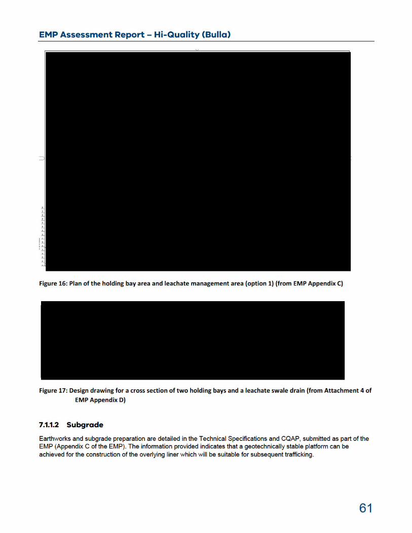
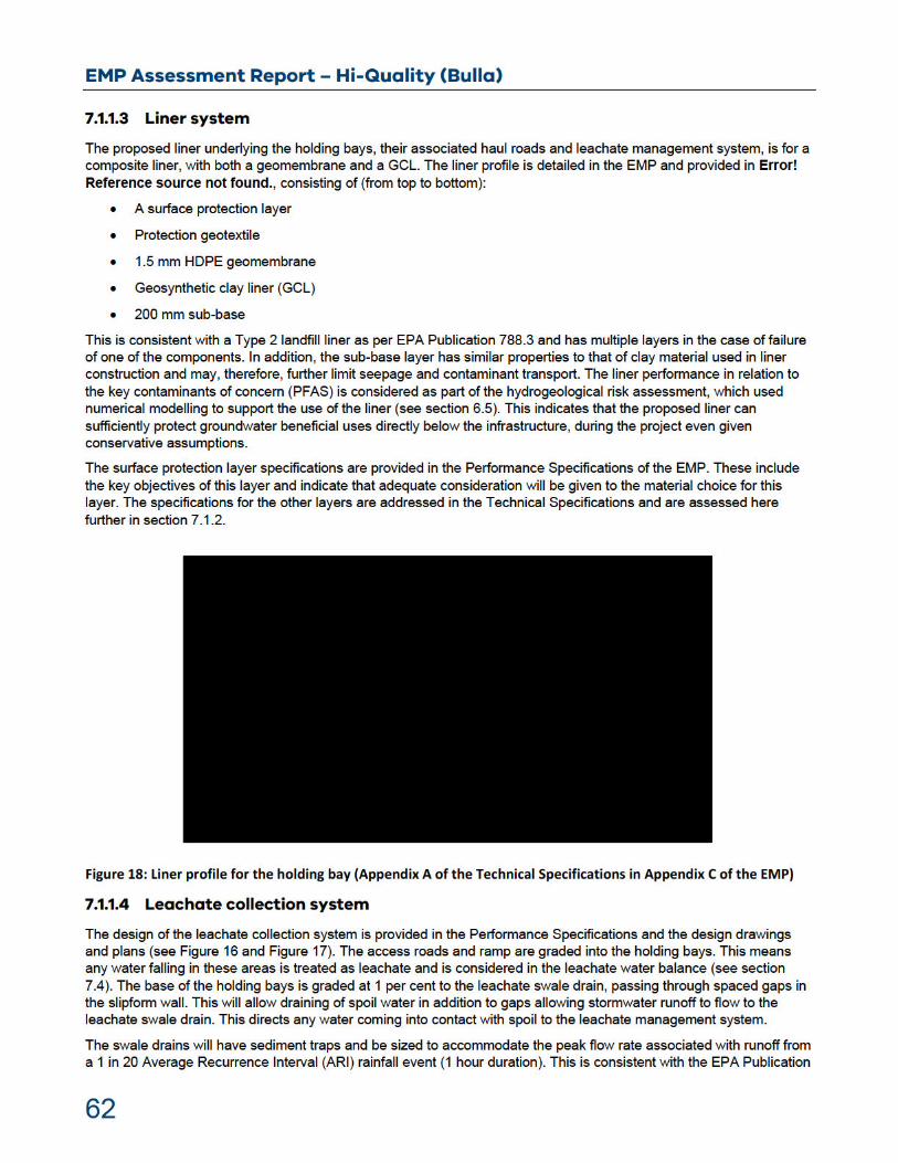

EMP Assessment Report – Hi-Quality (Bulla)
63
788.3 requirement for drainage measures for a putrescible landfill. In the event of higher rainfall events than considered, the inlet valve to the leachate ponds will prevent flooding of the leachate storage ponds.
7.1.1.5 Groundwater separation
The separation from groundwater in the vicinity of the holding bays is reported to be considerable, with a 40 m separation indicated based on the proximal monitoring bore MW4 (ADE Consulting 2018). This separation from groundwater is considered in the hydrogeological risk assessment. The low seepage and likely low PFAS diffusion rate through the proposed liner, limit reliance on this separation for the protection of groundwater. The separation of groundwater is, therefore, sufficient for the proposed activities and its thickness further limits potential for off-site PFAS migration.
7.1.1.6 Surface water management
Stormwater is to be managed as leachate if it falls within the holding bay access roads, the holding bays or the leachate management infrastructure. Rainfall falling outside of these areas is segregated from the leachate management system. The grassed earthen bund that borders the holding bays to the south and south west, will prevent surface water flow from this direction, downgradient into the holding bay area. Further stormwater provisions are detailed in the containment cell Design Report (Appendix E of the EMP), which includes a drainage line running around the holding bays to the west and north west, directing stormwater to the existing landfill to the north.
7.1.2 Technical specifications and CQAP The general method of construction of the preparatory earthworks, subgrade and liner components, are sufficiently detailed in the Technical Specifications. The provisions are in general accordance with relevant standards and industry best practice.
The proposed properties for the materials are in line with those of EPA Publication 788.3, industry best practice and other relevant standards. The properties of preparatory earthworks, subgrade and subbase appear to be sufficient to enable the construction of a stable base for the construction of the liner. The
properties are broadly in line with the specifications provided in EPA Publication 788.3, and Geosynthetic Research Institute (GRI)-GCL3 Standard Specification, GRI – GM13 Standard Specification and GRI -GT12(a) - ASTM Version Standard Specification, respectively.
All Construction Quality Assurance (CQA) testing of materials proposed to be used in construction of the holding bays liner are in line with the specifications detailed in EPA Publication 788.3. The Technical Specifications and CQA plan also detail Construction Quality Control (CQC) and CQA procedures for the construction of the liner, meeting the intent of EPA Publication 788.3. This includes appropriate independent third-party involvement in the construction to verify that this is in accordance with the design intent, via involvement of a Geotechnical Inspection and Testing Authority (GITA) (Level 1 Responsibility), CQA Inspector and Auditor. The Auditor will verify the construction works meets EPA's approved design documents. Relevant Auditor hold points are included in the CQAP, in accordance with those detailed in Appendix 12 of EPA Publication 1323.3, where relevant.
In summary, the Technical Specifications and CQAP, address all the relevant aspects typically required for landfill cell designs as per Appendix 10, 11 and 12 of EPA Publication 1323.3. The Technical Specifications demonstrate the specifications for the primary elements used in construction and construction approaches are broadly in line with best practice. The CQAP provides sufficient provisions to demonstrate that the holding bays liner will be constructed to meets its design requirements.
7.1.3 Holding bay design conclusions
EPA conclusions
EPA is satisfied that the Auditor assessed holding bays designs documents provided in the EMP, contain sufficient provisions to adequately manage environmental risks that may arise during holding bay construction and operation, and ensure the holding bays are constructed in accordance with the design.

EMP Assessment Report – Hi-Quality (Bulla)
64
7.2 Containment cell design assessment
The design of the containment cell (including its cap) is summarised in the EMP (section 7). Detailed design information is provided in Appendix E of the EMP, and includes a Design Report, Technical Specifications and a CQAP for the containment cell and a Technical Specification and CQAP for the containment cell cap. These documents were assessed by the Auditor and their assessment is provided in Appendix L of the EMP.
The detailed design documents are prepared in accordance with relevant information detailed in Appendices 9, 10, 11, 12 and 13 of EPA Publication 1323.3 (where relevant to this application). The Auditor concludes the risks posed to the environment will be acceptable, provided the Auditor’s recommendations are adopted.
The containment cell is designed to contain spoil that meets the acceptance criteria for the cell in regards PFOS+PFHxS and PFOA. The cell is to be located within a gully area at the Site and into an area of stockpiles and existing site activities. Its construction will require cutting and filling of this existing area.
To limit seepage and PFAS migration through the base of the cell, the cell design incorporates a composite liner (consistent with a Type 2 liner in accordance with EPA Publication 788.3), with the liner choice supported by modelling assessed further in section 6.4 of this report. To manage leachate, the designs have provisions for a leachate collection system and a leachate sump for removal of the leachate.
7.2.1 Designs
7.2.1.1 Plans and design drawings
The EMP includes maps and design drawings that detail the relevant aspects included in Appendix 9 of EPA Publication 1323.3 (“Preparation of plans (designs) for a new landfill cell”). This includes location maps, premises maps, cell plans, cell cross sections, liner profiles, leachate collection system plans and final cap contours. These plans detail the staging of the cell construction and the connection of later stages with earlier stages, to ensure leachate management and liner materials can be tied in.
The maps and plans appear to confirm the cell is designed in line with requirements typically applied to Type 2 landfill cells as per EPA Publication 788.3. Key deviations from EPA Publication 788.3 include the spacing of the leachate collection pipes, discussed further in section 7.2.1.4 of this report.
The maps provided in the EMP also include a provisional position for a 1-in-100 drainage channel, planned to run along the western batter of the containment cell. The planned drainage channel appears to go through the containment cell. It is not clear how this will be engineered, but it raises concerns regarding potentially supplying water for leachate generation and stability issues with the cell. As the drainage channel will follow at a later date details cannot be provided. However, when it is designed consideration needs to be given to the above potential risks and adequate controls put in place.
In conclusion, the maps and designs broadly indicate that the design meets the design objectives and that the cell can adequately manage environmental risks. This is also reliant on the additional design aspects addressed in the Design Report, Technical Specifications and the CQA Plan.

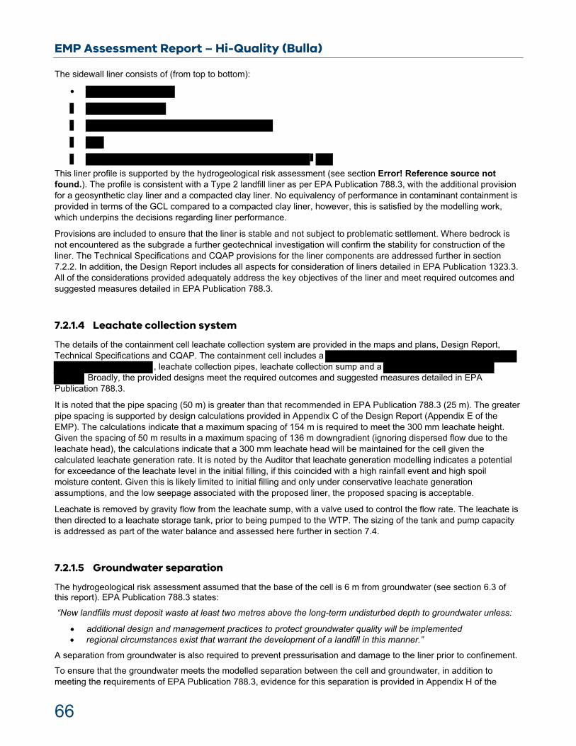
EMP Assessment Report – Hi-Quality (Bulla)
66
The sidewall liner consists of (from top to bottom):
This liner profile is supported by the hydrogeological risk assessment (see section Error! Reference source not found.). The profile is consistent with a Type 2 landfill liner as per EPA Publication 788.3, with the additional provision for a geosynthetic clay liner and a compacted clay liner. No equivalency of performance in contaminant containment is provided in terms of the GCL compared to a compacted clay liner, however, this is satisfied by the modelling work, which underpins the decisions regarding liner performance.
Provisions are included to ensure that the liner is stable and not subject to problematic settlement. Where bedrock is not encountered as the subgrade a further geotechnical investigation will confirm the stability for construction of the liner. The Technical Specifications and CQAP provisions for the liner components are addressed further in section 7.2.2. In addition, the Design Report includes all aspects for consideration of liners detailed in EPA Publication 1323.3. All of the considerations provided adequately address the key objectives of the liner and meet required outcomes and suggested measures detailed in EPA Publication 788.3.
7.2.1.4 Leachate collection system
The details of the containment cell leachate collection system are provided in the maps and plans, Design Report, Technical Specifications and CQAP. The containment cell includes a
, leachate collection pipes, leachate collection sump and a Broadly, the provided designs meet the required outcomes and suggested measures detailed in EPA
Publication 788.3.
It is noted that the pipe spacing (50 m) is greater than that recommended in EPA Publication 788.3 (25 m). The greater pipe spacing is supported by design calculations provided in Appendix C of the Design Report (Appendix E of the EMP). The calculations indicate that a maximum spacing of 154 m is required to meet the 300 mm leachate height. Given the spacing of 50 m results in a maximum spacing of 136 m downgradient (ignoring dispersed flow due to the leachate head), the calculations indicate that a 300 mm leachate head will be maintained for the cell given the calculated leachate generation rate. It is noted by the Auditor that leachate generation modelling indicates a potential for exceedance of the leachate level in the initial filling, if this coincided with a high rainfall event and high spoil moisture content. Given this is likely limited to initial filling and only under conservative leachate generation assumptions, and the low seepage associated with the proposed liner, the proposed spacing is acceptable.
Leachate is removed by gravity flow from the leachate sump, with a valve used to control the flow rate. The leachate is then directed to a leachate storage tank, prior to being pumped to the WTP. The sizing of the tank and pump capacity is addressed as part of the water balance and assessed here further in section 7.4.
7.2.1.5 Groundwater separation
The hydrogeological risk assessment assumed that the base of the cell is 6 m from groundwater (see section 6.3 of this report). EPA Publication 788.3 states:
“New landfills must deposit waste at least two metres above the long-term undisturbed depth to groundwater unless:
additional design and management practices to protect groundwater quality will be implemented regional circumstances exist that warrant the development of a landfill in this manner.”
A separation from groundwater is also required to prevent pressurisation and damage to the liner prior to confinement.
To ensure that the groundwater meets the modelled separation between the cell and groundwater, in addition to meeting the requirements of EPA Publication 788.3, evidence for this separation is provided in Appendix H of the

EMP Assessment Report – Hi-Quality (Bulla)
67
Design Report (Appendix E of the EMP). This reports groundwater level data from three bores within the cell footprint, one now decommissioned and two commissioned in 2019. The data indicates a minimum separation over the monitoring period of 6.9 m, between the lowest point of the cell and groundwater, measured during installation. This well is interpreted by the Auditor, and the well installation consultants (ADE Consulting Group 2018), as representing perched water. Other surrounding bores do report lower groundwater depths, supporting this hypothesis. All groundwater bores in this area of the Site, in the cell footprint and to the topographic high in the east have all reported groundwater levels lower than the one considered in the hydrogeological risk assessment, and, therefore, have a greater separation from groundwater.
It is noted that there is limited historical data for this area of the Site and also a lack of information for the southern end of the cell. However, based on the evidence provided, EPA agree with the Auditor, that the separation from groundwater appears to meet the modelled separation (6 m) and, therefore, likely exceeds the 2 m separation stated in EPA Publication 788.3.
7.2.1.6 Surface water management
Indicative pathways for stormwater swale drains are provided in the maps and plans of the containment cell in the EMP. In addition, design drawings are provided that detail the cross sections of typical surface water swale drains and erosion control measures. It is noted in the design documents that they are preliminary and may be adjusted, while still meeting the objectives. During construction, the Technical Specifications state that erosion and sediment controls will be enacted according with EPA Publication 1834 and EPA Publication 275.
The provided indicative information demonstrates that surface water will be adequately diverted around the cell, which is important given its location in a gulley feature and ensures segregation from the spoil containing areas. The provisions also include erosion and sediment control features in accordance with the suggested measure in EPA Publication 788.3. The designs do not include details of how they tie into the existing site stormwater management system or the capacity of stormwater management system. These are addressed by the Auditor and subject to two Auditor recommendations (#22 and #23).
7.2.1.7 Cap Design
As part of the design documents, a Technical Specification and a CQAP are provided for the containment cell cap. Information is also provided in the cell designs and includes the proposed cap profile, material specifications for the cap and proposed cap design. This is consistent with the information typically provided for landfill cell design documents, detailed in EPA Publication 1323.3. It is noted that the finalised design cannot be developed at this stage as the final waste volumes entering the cell will dictate the final cap design. These will be developed when the top of waste height is known.
The cap liner profile is in accordance with a typical Type 2 cap as per EPA Publication 788.3, from top to bottom:
This is consistent with the baseliner and it is assumed this would meet <75 per cent infiltration as seepage through the base.
The indicated cap design has grades of 5 per cent in accordance with the grades recommended in EPA Publication 788.3.
EMP Assessment Report – Hi-Quality (Bulla)
68
7.2.2 Technical specifications and CQAP The general method of construction of the preparatory earthworks, subgrade and liner components, are sufficiently detailed in the Technical Specifications. The provisions are in general accordance with relevant standards and industry best practice, including considerations detailed in EPA Publication 788.3.
The proposed properties for the materials are in line with those of EPA Publication 788.3, industry best practice and other relevant standards. The properties of preparatory earthworks and subgrade appear to be sufficient to enable the construction of a stable base for the construction of the liner. Noting that further geotechnical investigations may inform further corrective actions to improve strength and stability.
broadly in line with the relevant specifications provided in EPA
Publication 788.3, and Geosynthetic Research Institute (GRI)-GCL3 Standard Specification, GRI – GM13 Standard Specification and GRI -GT12(a) - ASTM Version Standard Specification respectively.
CQA testing of materials proposed to be used in construction of the containment cell and cap liner are broadly in line with the frequencies detailed in EPA Publication 788.3. The Technical Specifications and CQAP also detail CQC and CQA procedures for the construction of the cell meeting the intent of EPA Publication 788.3. This includes appropriate independent third-party involvement in the construction to verify that this is in accordance with the design intent. This includes involvement of a GITA (Level 1 Responsibility), CQA Inspector and Auditor. The Auditor will verify the construction works meets EPA's approved design documents. Relevant Auditor hold points are included in the CQA Plan, in accordance with those detailed in Appendix 12 of EPA Publication 1323.3, where relevant to this application.
In review of the Technical Specifications and CQAP (summarised above), EPA concur with the assessment and conclusions of the Auditor. The documents provide sufficient detail to adequately manage environmental risks that may arise during cell and cap construction and operation, and ensure the cell and cap is constructed in accordance with the design.
The Technical Specifications and CQAP address all the relevant aspects typically required for landfill cell and cap designs as per Appendix 10, 11 and 12 of EPA Publication 1323.3. The Technical Specifications demonstrate the specifications for the primary elements used in construction and construction approaches are broadly in line with best practice. The CQAP provides sufficient provisions to demonstrate that the containment cell liner will be constructed to meets its design requirements.
7.2.3 Containment cell design conclusions
EPA conclusions
EPA is satisfied that the Auditor assessed containment cell and cap design documents provided in the EMP, contain sufficient provisions to adequately manage environmental risks that may arise during containment cell construction and operation, and ensure the containment cell and cap are constructed in accordance with the design.
7.3 Leachate pre-treatment ponds
The design of the leachate pre-treatment ponds is summarised in the EMP (section 6). Detailed design information is provided in Appendix C of the EMP, and includes Performance Specifications, Technical Specifications and a CQAP. The Technical Specifications and CQAP include considerations detailed in Appendix 11 and Appendix 12 of EPA Publication 1323.3 (where relevant to this application). A holistic site water balance was provided in Appendix D of the EMP, which informs the capacity of the pre-treatment leachate holding ponds and other aspects of the leachate management system (assessed further in section 7.4 of this report). These documents were assessed by the Auditor and their assessment is provided in Appendix L of the EMP.

EMP Assessment Report – Hi-Quality (Bulla)
69
The documents provided as part of the EMP are sufficient to make an assessment of the leachate pre-treatment pond design to ensure they meet the design intent. The Auditor concludes the risks posed to the environment will be acceptable, provided the Auditor’s recommendations are adopted.
The Performance Specifications detail the key design objectives which the pre-treatment leachate ponds designs must meet, including pond size, location, capacity, inlets and outlets and sediment control. They also include plans for the holding bays and pre-treatment ponds layout, which principally concerns the segmentation of the holding bays and the location, number and capacity of the leachate holding ponds. The Performance Specifications also state that an alternative layout may be proposed by the contractor, with any changes to the leachate management capacity requiring further EPA approval. This is appropriate to ensure sufficient leachate capacity is appropriately considered.
The pre-treatment leachate ponds are proposed to be in one of two arrangements, with either three ponds or five ponds, depending on the arrangement decided on. The Performance Specifications indicates that the total capacity of these ponds will be , excluding the
7.3.1 Design
7.3.1.1 Plans and design drawings
The location of the pre-treatment ponds in the context of the wider Sunbury Waste Management Facility site and its surrounds, is provided in the EMP (Figure 2 of Appendix A). The concept plans provided for option 1 and 2 of the holding bay area are provided in the EMP (Appendix A of Appendix C of the EMP and option 1 in Figure 15 of this report). These detail the location and footprint of the pre-treatment leachate ponds.
Indicative design drawings for the pre-treatment ponds are provided in the EMP (Attachment 4 of EMP Appendix D). These include a cross section and plan of an indicate pre-treatment leachate pond (Figure 20). In addition, the pre-treatment pond liner profile and anchor trench are provided in Appendix A of the Technical Specifications (Appendix C of the EMP).
The provided maps, plans and indicative design drawings, broadly meet many of the relevant components detailed in Appendix 9 of EPA Publication 1323.3. The provided design drawings for the ponds are limited in detail, however, the Performance Specifications, Technical Specifications and CQAP together address the key environmental protection objectives of the leachate pond. The Performance Specification states that final design drawings will be prepared, including 3D surface models, in general accordance with Appendix 9 of EPA Publication 1323.3. This is appropriate guidance to follow and if prepared in accordance with the information in the EMP will meet the design intent.


EMP Assessment Report – Hi-Quality (Bulla)
73
The leachate water balance considered two consecutive 90th percentile rainfall years (1963 repeated twice) for the containment cell, using observational data from a weather station in proximity to the Site. This satisfies the above EPA Publication 788.3 requirement. The holding bay area considered a two-year period that was collectively a 90th percentile rainfall period (1963 and 1964). Although resulting in a lower total than two consecutive 90th percentile rainfall years, this is a reasonable approach to consider a higher rainfall period. The leachate water balance also estimated contribution from spoil water, using information on the possible moisture content of the spoil and making assumptions of its field capacity. It is noted that significant uncertainty is associated with estimating spoil water drainage once arrived at the Site, however, the approach taken to estimating uses conservative assumptions and is, therefore, a reasonable approach.
The water balance uses the Hydrologic Evaluation of Landfill Performance (HELP) to estimate the leachate production in the containment cell for various filling and capping stages. This is the industry standard approach to estimating this and the inputs and outputs for this estimation are reasonable and likely conservative. All rainfall on the holding bays is assumed to be captured as leachate for management, while evaporation and drainage from the spoil are also estimated. The assumptions underpinning these calculations are reasonable.
The water balance for the containment cell informs the sizing of the leachate holding tank, which is sized ( ) to hold the peak daily leachate production for the cell (calculated to be ). The pump used to supply leachate to the WTP has a capacity of This pumping rate has been adopted for the water balance modelling. When compared to the peak daily leachate production, this pump capacity is sufficient to enable the 300 mm leachate head in the cell to be met for all except one day of the modelled period. However, given the conservative assumptions on spoil moisture entering the cell and the high rainfall events considered, the proposed capacity is reasonable.
The water balance for the holding bay area informs the required pre-treatment storage capacity. The water balance assumes flow to the WTP of hours a day. This capacity is enough to ensure, on a monthly basis, the proposed leachate storage capacity is not exceeded considering the peak monthly leachate production. It is noted that individual rainfall events may exceed the daily capacity to the WTP, however, in the short term these storm events can be managed by constricting the inflow into the ponds using a valve. This may rely on short term storage capacity in the holding bays area.
Considering the leachate production rate for the holding bays and the containment cell combined, the proposed 3 ML WTP will have sufficient capacity to treat the leachate at all times. A series of six 250,000L storage tanks will be used to store water prior to reuse or disposal to a site licensed to accept industrial waste of that kind.
EPA conclusions
The leachate water balance has been prepared using conservative assumptions in regards leachate volumes produced, assuming high volumes of leachate production.
EPA is satisfied that the system is then designed to be able to manage the resulting leachate volumes and that redundancy to cope with high volumes of leachate will be available. The water balance, therefore, supports the proposed leachate management for the Site.
7.5 Leachate treatment
The proposed leachate treatment system consists of preliminary treatment to make leachate suitable for further treatment and subsequent treatment to remove PFAS.
Initial clarification of leachate is designed to occur in the lined leachate holding ponds where the majority of the solid particles are expected to settle.

EMP Assessment Report – Hi-Quality (Bulla)
74
Detailed information about wastewater treatment plant has been provided in section 8 of the EMP. Design criteria and assessment against the criteria, including removal efficiencies, for each treatment train should be developed and provided to confirm that the proposed treatment train can achieve required treated water quality. Dewatered sludge will be tested and based on the test results and the solid residue will be disposed at an appropriate licensed facility.
EPA conclusion
The proposed design and methods for leachate treatment is acceptable. Routine operations and maintenance checks will be undertaken to confirm the operational plant performance.

EMP Assessment Report – Hi-Quality (Bulla)
75
8 Environmental Management Assessment
The EMP identifies various operations undertaken at the spoil management facility and containment cell, broadly falling under the following headings:
Initial processing of spoil
Leachate
Classification of spoil
Reuse, containment, or disposal of spoil
Reuse or disposal of treated water.
Various requirements for operations were identified as part of EPA’s assessment. They are reproduced below as sub-headings, with the extent that the application met them, discussed.
The environmental monitoring and inspection program is proposed in the EMP and the Operational Management Procedures (OMP) (Appendix H of the EMP). These sections contain all of the information for a monitoring program that is required of landfills as per EPA Publication 1323.3. The selection of analytes, procedures, field records, QA/QC and PFAS sampling procedures appear to be well informed by existing guidance and adequate for the monitoring required. Some specific details are highlighted below, including assessment and recommendations.
8.1 Spoil Management
Spoil management activities in the EMP include tracking of spoil at the weighbridge and spoil sampling and classification. Further details are provided in section 4.1 above.
8.1.1 Disposal in the containment cell Some procedures are given for spoil bay management or containment cell management for control of dust. Use of treated leachate from the spoil bays is mentioned for use as dust suppression in the water balance and in various sections of the EMP. . Treated leachate from the leachate ponds is proposed to be used for dust suppression in the containment cell.
EPA conclusions
The proposed acceptance criteria for the spoil at the Site is above EPA’s interim criteria for reuse (as per EPA Publication 1669.3). Therefore, some management and controls measures must be in place, such as placement in a containment cell. A plan for the containment cell describing various landfill type procedures has been provided, which includes management of the spoil and potential dust management requirements.
8.1.2 Containment cell compliance sampling Periodic sampling and analysis of spoil prior to being deposited in the containment cell is proposed to be undertaken to ascertain if it meets the containment cell acceptance criteria. This is in line with the spoil classification testing regime which references the sampling analysis quality plan, developed by CPB/JH JV, undertaken in the holding bays and provides confidence that the spoil classification testing is robust. Frequency of sampling can be on a sliding scale governed by consistency of results and hence confidence in the classification sampling and analysis.
EPA conclusions
There is a requirement for periodic sampling of waste in the containment cell to ensure it meets the cell acceptance criteria. This has been addressed through the SAQP prepared by CPB/JH JV

EMP Assessment Report – Hi-Quality (Bulla)
76
8.1.3 Prescribed industrial waste disposal The EMP states:
Category C Contaminated Soil will be transferred and disposed to the on-site Category C licensed Cell within EPA Licence 45279.
Category B and A PIW Contaminated Soil will be transferred to the proposed on-site PIW treatment area for immobilisation and reclassification prior to ultimate disposal.
The GHD documents state that PIW that cannot be disposed of at the Hi-Quality licensed landfill will be disposed of to an off-site licensed facility. Additionally, the chance of PIW needing to be disposed of is described as unlikely. With this in mind, it is considered unlikely that Hi-Quality would commit to such infrastructure to dispose of PIW beyond its existing landfill cells for Category C PIW. All disposal of PIW soil will be tracked and logged using EPA’s electronic waste transport certificate system.
EPA conclusions
Disposal of all PIW waste soils will occur at EPA licensed facilities, using appropriate tracking methods.
8.1.4 Existing Soil A baseline study of the Site has been recommended and undertaken as part of the monitoring plan. To understand the background levels prior to infrastructure being constructed, and to inform rehabilitation actions post-closure, samples will be taken from key soil management areas. This should include the surface underneath the temporary soil holding bay area. This data can then inform increases in PFAS concentrations as a result of soil processing activities at the Site.
EPA conclusions
EPA agrees with the approach to sample before and after the operation of the holding bay area to inform rehabilitation actions, where required.
8.2 Groundwater
The EMP states that a baseline groundwater program will be undertaken to assess for current conditions. Sampling is due to occur from groundwater wells MB1 to MB19. Once operational it is proposed to undertaken groundwater sampling and monitoring quarterly at all groundwater wells. It is proposed to measure and sample for: groundwater levels, temperature, electrical conductivity, oxidation-reduction potential, pH, redox, dissolved oxygen, total dissolved solids, total suspended solids, major ions, metal, nutrients, PFOS, PFHxS and PFOA.
Samples are proposed to be taken every three months after spoil disposal commences and after completion of operations for a length of time determined by the aquifer hydraulic conductivity (K). If impacts are not observed at down-gradient bores after a time when the conductivity would be expected to have transported contaminants to those bores, then monitoring may be reduced to biannual. In addition, prior to disposal of spoil, additional PFAS sampling and testing in groundwater and surface water will be undertaken to establish background levels.
The current and proposed groundwater monitoring networks are presented in Figure 23. The EMP states that one up hydraulic gradient groundwater monitoring bore is present. This is the minimum requirement in guidance but could be considered insufficient to determine the hydraulic gradient in this case due to hydrogeological complexity and project profile. This appears to be recognised, as further bores are proposed surrounding the soil containment area (MB16, MB17, MB 18 and MB19). Groundwater bore locations and installation dates are required for EPA to determine if the network is sufficient. The new bores must be installed and developed prior to any spoil acceptance.
The sampling methodology, analytes list and quality assurance and controls appear to be appropriate and in accordance with EPA guidelines and Australian Standards.

EMP Assessment Report – Hi-Quality (Bulla)
77
EPA conclusions
EPA is satisfied that the EMP addresses the risk to groundwater by proposing a monitoring plan for this aspect.
All leachate management will be undertaken within appropriately bunded areas to prevent potential groundwater contamination.


EMP Assessment Report – Hi-Quality (Bulla)
79
8.3 Surface water
Appropriate infrastructure and management have been included for considering stormwater and sediment control to protect the adjacent surface waters and groundwater. Hence, surface run off and stormwater in this area needs to be effectively managed. Monitoring of surface water quality around the Site has been considered and is addressed in detail. In addition, surface water that contacts the spoil in the cell must be and will be treated as leachate. The nature of the spoil is likely to lead to a significant run-off component which will be collected and directed to the leachate management system.
Surface water is proposed to be monitored at four creek locations (EC01 to EC04) one quarry sump location (QS1) and within a number of sumps in the holding bay and containment cell areas. The four creek sampling locations will be sampled biannually. The quarry and leachate sumps in the spoil management areas will be sample monthly for the first four months. The frequency will then be assessed based on initial results. An initial baseline study is proposed to be undertaken. The sampling methodology is consistent with the protocols listed in EPA Publication IWRG701. The following parameters will be determined: temperature, electrical conductivity, dissolved oxygen, oxidation-reduction potential, pH, physical appearance (turbidity, sheen, odour, sediment load) and PFAS. Further, field blanks will be taken as part of the quality assurance processes, as follows: two rinsate blanks and two trip blanks. In addition, two groundwater quality field duplicate samples and two field splits will be collected to meet the monitoring program requirements.
In the event PFAS concentrations increase in any surface water or ground water location, then the source of the increase will be investigated, and it is proposed to undertake aquatic biota sampling.
EPA conclusions
EPA is satisfied by the proposed monitoring plan for surface waters.
EPA supports proposed establishing of background levels of PFAS in sediment and biota in addition to the previously collected surface and ground water locations. This sampling will be conducted prior to receipt of soil.
95 per cent species protection level for PFOS (0.13 µg/L) is acceptable due to background data (water, sediment and biota) being collected.
EPA will receive results from the biannual monitoring plan to contain PFAS sampling for water and sediment, and the annual monitoring plan to include PFAS-sampling for biota if PFAS levels in water and sediment increase over time.
As part of the audit process, records of the biannual and annual monitoring data (including PFAS) will be checked and assessed by EPA.
8.4 Leachate
Leachate monitoring is considered in depth in the EMP and the OMP. The containment cell is described in the application documents as having that will be required to maintain a maximum 300 mm leachate head prior to leachate disposal/treatment. As this water will have contacted the spoil, it must be considered leachate and accounted for in water balances for leachate collection, transfer, temporary storage and treatment. Leachate in this scenario therefore includes water generated from the spoil (spoil water) or that lands within the spoil management areas and comes in contact with the spoil. All leachate that exceeds the proposed trigger levels will be required to be treated to concentrations below the trigger levels prior to reuse or disposal to a site licensed to accept industrial waste of that kind. It is proposed to treat the water to levels below the Australian Drinking Water Guidelines. Leachate levels in the containment cell sump/s will be monitored by a permanent depth monitoring device including an automated alarm system and also gauged on a monthly basis.
Lined leachate holding ponds are proposed in this application to supply the water/leachate treatment plant. If the retention time in the ponds is short, the modelling parameters are sufficiently conservative and indicative of protection
EMP Assessment Report – Hi-Quality (Bulla)
80
of groundwater and groundwater monitoring is robust, this may be acceptable. Modelling indicates the ponds will be protective of the underlying groundwater at the trigger levels set in the EMP, beyond the intended project timeline.
A monitoring plan is provided for the treated leachate in the leachate pond, holding tanks, and the containment cell sump. Sampling is scheduled to include temperature, electrical conductivity, dissolved oxygen, oxidation-reduction potential, pH, physical appearance (turbidity, sheen, odour, sediment load), total dissolved solids, total suspended solids, major ions, industrial waste resource regulation waste suite (IWRG 621), nutrients, oxygen demand, PFOS, PFHxS and PFOA. Sampling and quality assurance is proposed to be undertaken in accordance with EPA guidelines and Australian Standards.
Treated leachate is proposed to be sampled with the same parameters. Samples are proposed to be collected from the holding tank at an estimated weekly frequency, dependant on through put of water. The rate of testing may increase or decrease based on the volume of leachate generated.
. For long term monitoring this is likely to be sufficient as it is used in combination with spoil acceptance leachate testing.
EPA conclusions
EPA is satisfied by the proposed leachate monitoring.
EPA will receive the results of the leachate sampling once conducted.
Reporting of the leachate monitoring must be provided as part of the Audit process.
8.5 Air quality
Given the high moisture content of the material (50-58 per cent), it is not expected that there would be a significant risk of additional dust impacts at the Site. The application has considered the potential sources of dust emissions, which include the transportation and unloading of material as well as the unsealed road surfaces. The measures that have been proposed should be sufficient to deal with any potential dust and minimise any off-site dust impacts.
Hi-Quality have some dust deposition gauges installed, this will allow for assessment and monitoring of dust impacts and allow for preventative steps to be taken. This is in addition to using visual inspections to activate additional controls.
In addition to this, there will be consideration of proactive assessment prior to any dust events occurring, this could include daily checks of weather such as lack of rainfall and predicted high wind speeds to help assess if additional dust controls are required before a dust event occurs.
The spoil will have been dewatered prior to acceptance into this cell and will progressively dry out after deposition. Dust will likely be created during the approximately 16 months of ongoing vehicle movements and spoil deposition in this cell. The proposed dust/particulate monitoring program is required to inform the efficacy of dust management practices in the containment cell and to act as early warning when excessive dust is generated to prevent PFAS transmission off-site.
In terms of odour, in the EMP the proponent states: ‘Any odour sources located within the WTP will be covered if necessary, to minimise odorous emissions’. Given the nature of the material it is unlikely that impact from odour will occur from the spoil.
EPA conclusions
EPA is satisfied with the proposed air quality management approach. A review of the dust management procedures following establishment of the Site and initial receipt of spoil will be undertaken.

EMP Assessment Report – Hi-Quality (Bulla)
81
8.6 Noise/vibration
Construction
Night period
Based on the noise assessment provided, EPA understands that all construction is to occur during the day and evening period with no works anticipated during the night period.
Day period
Where EPA guidelines do not provide noise criteria, the most appropriate approach is to demonstrate application of requirements and measures implemented to reduce the impacts. EPA publication 1834 lists provisions regarding community consultation, work scheduling, and work requirements which includes requirements and measures to be applied.
The intent of EPA guidelines for construction noise is that the first consideration is to minimise construction noise as far as reasonably practicable. The requirements listed in section 4 of EPA publication 1834 provide requirements and measures to be applied in the first instance prior to considering compliance to specific noise levels.
Construction activities will have to be managed in accordance with these requirements. In the first instance, noise emissions should be minimised as far as reasonably practicable by implementing best practice noise control measures. Residual noise should then be assessed and its impacts addressed.
We also note that the current pandemic situation has resulted in more people working from home during the day period than usual, and people having to stay at home in the evening/weekend periods. It can be expected that the opportunities for people to cope with the noise are more limited. It is likely that this will remain the case in the foreseeable future.
Evening period
EPA notes there will be exceedances of up to 11 dBA cumulative during the evening period predicted during construction, particularly concerning earthworks. Specific measures recommended are to be implemented and further actions to mitigate or otherwise manage noise and its impacts will be considered and implemented as far as reasonably practicable.
Note: EPA observes that while the background level referred by the acoustic consultant for determining construction noise criteria is defined as the ‘90th percentile of LA90’, EPA publication 1254 requires that the measurement of the background level represents the background at the time of impact.
Mitigation measure overall
EPA agrees with the recommendation that mitigation measures should be implemented to reduce the impact on nearby sensitive receivers. Confirmation of the effective implementation of noise mitigation measures should be sought via follow-up assessment to verify compliance.
This should not only involve noise monitoring, but also adequate information and training of employees, contractors and vehicle drivers, supported by audit/inspection procedures in place to ensure that practices and behaviour are consistent with good practice management of noise emissions. This should be included in the daily and/or weekly inspection checklists provided in Appendix D of the OMP.
Low frequency noise from activities, which may include rumbling from heavy machinery in use, should also be addressed for both construction and operation of the spoil processing and management facility.
The A-weighted indicators LAeq and LAmax provide a limited representation of the noise at low frequencies. Consideration is to be given to truck idling and revving between the frequencies of 40 Hz to 80 Hz, for which EPA is particularly concerned given the anticipated number of heavy vehicles.
Monitoring is proposed to be undertaken to verify compliance in accordance with SEPP N-1.

EMP Assessment Report – Hi-Quality (Bulla)
82
EPA conclusions
EPA is satisfied by the proposed noise monitoring. Noise is to be minimised as far as reasonably practicable – for both construction activities and
operations –prior to considering compliance to the relevant noise limits or criteria. Where there are no noise criteria provided in the guidelines, the most appropriate approach is to
demonstrate application of the provisions of the guidelines and measures implemented to minimise or otherwise address the impacts.
A copy of the proposed follow-up noise assessment will be provided to EPA, to verify spoil processing and management facility once operational with SEPP N-1.
A copy of a noise management plan is to be provided to EPA. This plan would need to be explicitly considered and referred to in the noise assessment. This involves that it has been prepared in collaboration with the acoustic consultant, or as a minimum that it had been reviewed by them. We understand that such a plan will consider appropriate requirements and guidance by relevant authorities with regards to the proposal.
8.7 Other management activities
Various other management activities are included in the EMP, including management of hazardous chemicals, flora and fauna, waste management and weed and pest management. These appear to be sufficient and have been prepared citing the relevant guidance.
The HHERA listed ecological receptors that may encounter PFAS across the Site. The maned duck was selected as an indicator species for the Site, as it has been observed in the surrounding area and may use the leachate holding ponds. Ingestion of leachate contained in the on-site storage ponds was listed as a potential route of exposure.
Because the leachate levels at the Site are currently unknown, and PFAS-levels in waterfowls or other birds visiting the Site are unknown (for example, lack of data), the identified trigger values (250 µg/L PFSAs and PFCAs) for a bioaccumulating compound such as PFAS are not conservative enough. Therefore, the most suitable management option is to restrict access of birds to the leachate ponds. This will also prevent indirect exposure route to the surrounding ecosystem. Birdlife, such as wetland waders, may be particularly affected by contaminated soils, as highlighted by NEMPv2.
EPA conclusions
EPA agrees that access of birdlife to the on-site storage ponds is restricted, as described in the EMP.
8.8 Rehabilitation
Limited provisions for the rehabilitation of the Site are provided in the EMP, however further details are provided in section 13 of the OMP. Rehabilitation of the SWMF area is proposed to include removal of the spoil storage bays, leachate ponds, water treatment plant, bunds and access roads. It is proposed to rehabilitate the Site by capping the containment cell, as discussed above.
A soil validation testing program is planned to be undertaken to demonstrate that here has been no impact to the subsurface beneath the temporary structures. Any impacts are proposed to be remediated if required.
The preparation of a detailed rehabilitation and after care management plan is proposed to be developed following completion of the cells. EPA will review this plan. A high – level summary of the plan is provided which covers the key elements, however a detailed review would be required once the plan is produced. EPA recognises that there is little benefit in producing this plan prior to knowing the volume and characteristics of the material to be stored in a containment cell.
Additional to the information in the EMP, assessment of the PFAS levels at the Site post closure is proposed to be established to inform remedial action, if needed.
EMP Assessment Report – Hi-Quality (Bulla)
83
EPA conclusions
EPA will review a copy of the detailed rehabilitation and after-care management plan once it is prepared.
EPA will review validation sample results following the completion of testing and remediation (where applicable).
8.9 Reporting
Reporting details are provided in the EMP and OMP, which is appended to the EMP. Reporting is proposed to include pollution incidents, environmental monitoring events, tracking of waste volumes and disposal locations, quantity of leachate removed, treated and either disposed or reused, non-compliance incidents. This is consistent with EPA’s expectation with regards to the type of information to be reported or recorded.
It is expected that EPA will receive a copy of the reporting of environmental monitoring events following each monitoring event (for example, quarterly).
It is stated that records will be kept on site for a minimum of two years following completion of works, in accordance with the Regulations.
8.9.1 Pollution Incident Plan
Details of contingency actions to be undertaken in the event of a exceedances of adopted trigger levels has been provided. The plan states that EPA will be informed of any pollution incidents or escape, spill or leak of waste outside of the containment areas as soon as practicable. This meets EPA’s expectations for potential pollution response. The plan summarises adequately details for response for each of groundwater, leachate, treated water, surface water, dust and noise.
EPA is satisfied with the details provided related to the pollution incident management plan in the EMP.
8.10 Auditing
An independent Environmental Auditor has been engaged to review the EMP, including detailed design documents, technical specifications and construction quality assurance plan. A report prepared by the auditor assessing the suitability of the detailed designs, technical specifications, construction quality assurance plan, monitoring program and pollution incident plan is presented in Appendix L of the EMP. The auditor’s assessment was undertaken against the requirements of the Regulations and supports the EMP, concluding:
The Sunbury Waste Management Facility should achieve the requirements and objectives of the Environment Protection (Management of Tunnel Boring Machine Spoil) Regulations 2020 provided the infrastructure is constructed as per the design documents and the monitoring program and the pollution incident plan are implemented.
An independent auditor is also proposed to be engaged to undertake an audit of the construction of the spoil management infrastructure. A letter is to be prepared and provided to EPA on completion of construction, prior to receipt of waste spoil. The construction audit is proposed to be undertaken with consideration to EPA publication 788.3 and 1323.3. Reporting is currently proposed to be annually, in line with the current s53V operational audit undertaken on the adjacent landfill operations. A geotechnical verification is also to be undertaken in accordance with EPA publication 1323.3.
In addition, a six-monthly verification report is proposed to be produced by the independent auditor which will assess compliance with the requirements of the classification.
During operation of the spoil management facility, risk of harm audits are also proposed. These are to assess that the Site is operating in accordance with the EMP.
EPA conclusions
EMP Assessment Report – Hi-Quality (Bulla)
84
EPA is satisfied that an Auditor has undertaken an audit of the suitability of the detailed designs, technical specifications, construction quality assurance plan, monitoring program and pollution incident plan.
EPA is also satisfied with the proposed future scope of audits during and after both construction and operation of the proposed facility.
EMP Assessment Report – Hi-Quality (Bulla)
85
9 References
ADE Consulting Group (2018). Groundwater baseline assessment – acid sulfate soils (ASS Treatment Area, Hi-Quality Landfill)
Anderson, R. H., Adamson, D. T., & Stroo, H. F. (2019). Partitioning of poly-and perfluoroalkyl substances from soil to groundwater within aqueous film-forming foam source zones. Journal of contaminant hydrology, 220, 59-65.
Commonwealth of Australia (2012). Australian Groundwater Modelling Guidelines.
Department of Environment and Climate Change NSW (2009). Interim Construction Noise Guideline.
Di Battista, V., Rowe. R.K., Patch, D. and Weber, K. (2020) PFOA and PFOS Diffusion through Geomembranes at Multiple Temperatures, Waste Management, v117, 93-103.
EPA Victoria Publication 688 (2006). Hydrogeological Assessment (Groundwater Quality Guidelines).
EPA Publication IWRG701 (2009). Sampling and Analysis of Waters, Soils and Waste.
EPA Publication IWRG702 (2009). Soil Sampling
EPA Victoria Publication 788.3 (2015). Best Practice Environmental Management. Siting, design, operation and rehabilitation of landfills.
EPA Victoria Publication 1254 (2008). Noise control guidelines.
EPA Victoria Publication 1323.3 (2016). Landfill licensing.
EPA Victoria Publication 1669.2 (2019). Interim position statement on PFAS.
EPA Victoria Publication 1669.3 (2019). Interim position statement on PFAS.
EPA Victoria Publication 1834 (2020). Civil Construction, Building and Demolition (CCBD) guide.
Felizeter S, McLachlan MS, De Voogt P. Root uptake and translocation of perfluorinated alkyl acids by three hydroponically grown crops. J Agric Food Chem. 2014;62(15):3334-3342.
GHD 2017, Cell 3 and leachate pond upgrade HELP modelling memorandum, dated 7 March 2017.
GHD (2018), Report for Hi-Quality Products Pty Ltd – Bulla Landfill Hydrogeological Assessment, 3135157, September 2018.
GHD (2019), Bulla Landfill Monitoring 2019, June 2019 Monitoring Event, August 2019.
GRI Test Method GCL3. Standard specification for test methods, required properties, and testing frequencies of geosynthetic clay liners (GCLs). Revision 1: 30 March 2009, Geosynthetic Research Institute, Folsom, PA, USA
GRI Test Method Geomembrane 13. Standard specification for test methods, test properties and testing frequency for high-density polyethylene (HDPE) Smooth and Textured Geomembranes. Revision 9: June 1, 2009, Geosynthetic Research Institute, Folsom, PA, USA.
GRI Test Method GT12 (a). ASTM version. Standard specification for test methods and properties for nonwoven geotextiles used as protection (or cushioning) materials. Original: 18 February 2002, Geosynthetic Research Institute, Folsom, PA, USA.
Guelfo, J.L., Higgins, C.P. 2013. Subsurface transport potential of perfluoroalkyl acids at aqueous film-forming foam (AFFF)-impacted sites. Environmental science & technology. v47. 4164-4171.
ISO 9613-2 (1996) Acoustics – Attenuation of sound during propagation outdoors – Part 2: General method of calculation
Li, Y., Oliver, D. P., & Kookana, R. S. (2018). A critical analysis of published data to discern the role of soil and sediment properties in determining sorption of per and polyfluoroalkyl substances (PFASs). Science of the Total Environment, 628, 110-120.
Nolan (2019). Section 53V Audit – Landfill operation audit, Hi-Quality landfill, Service order no. 8005772, Nolan Consulting Pty Ltd.
NSW EPA (2017). Noise Policy for Industry.
PFAS National Environmental Management Plan Version 2.0 (2020). National Chemicals Working Group of the Heads of EPAs Australia and New Zealand
EMP Assessment Report – Hi-Quality (Bulla)
86
Ramsey (2020) White paper - Containment of PFAS type materials with geosynthetics. Boyd Ramsey Consulting LLC.
Rowe, R.K. 2004. Long-term performance of contaminant barrier systems. Geotechnique. v55. 631-678.
Sangam, H. P., & Rowe, R. K. (2001). Migration of dilute aqueous organic pollutants through HDPE geomembranes. Geotextiles and Geomembranes, 19(6), 329-357.
State Environment Protection Policy (Waters) 2018. Victoria Government Gazette, No. S 499.
Zareitalabad, P., Siemens, J., Hamer, M., & Amelung, W. (2013). Perfluorooctanoic acid (PFOA) and perfluorooctanesulfonic acid (PFOS) in surface waters, sediments, soils and wastewater–A review on concentrations and distribution coefficients. Chemosphere, 91(6), 725-732.