Embed Size (px)
Citation preview

EMR-5000™
User’s Guide
Document Number 100-0058-02 (A)

EMR-5000 User’s Guide version 2.3
August 2002
Published by
SkyStream Networks®
455 DeGuigne DriveSunnyvale, CA 94085-3890Copyright © 1998-2002 by SkyStream Networks.All rights reserved. No part of the contents of this book may be reproduced or transmitted inany form or by any means without the written permission of the publisher.
ContributorsTechnical Publications: Jonn Lavinnder and Regina Simmons
SkyStream Networks Engineering Department
Restricted rights This document contains proprietary and confidential information of SkyStream Networks.The contents of this document may not be disclosed to third parties, copied or duplicated inany form, in whole or in part, without the prior written permission of SkyStream Networks.
Use, duplication, or disclosure of the technical data contained in this document is subject torestrictions as set forth in subdivision (c)(1)(ii) of the Rights in Technical Data and ComputerSoftware clause at DFARS 52.227-7013 and/or in similar or successor clauses in the FAR, orin the DOD or NASA FAR Supplement. Unpublished rights reserved under the CopyrightLaws of the United States. Contractor/manufacturer is SkyStream Networks, 455 DeGuigneDrive, Sunnyvale, CA 94085-3890, USA. SkyStream is a registered trademark of SkyStreamNetworks. All other names are trademarks of their respective owners. SkyStream Networksowns the following patents: U.S. Patent No. 6351474, 6351471, 6292490, 6246701, 6195368,6148082, 6111896, 6064676 and has additional U.S. patents pending.
Software license and warrantyATTENTION! Use of the software program on the enclosed disks and/or installed on the computer issubject to the terms of the License Agreement printed on the license card, in the licensebooklet, or in the user documentation. You should not use this software until you have readthe License Agreement.
By using the software, you signify that you have read the License Agreement and accept itsterms.
LicenseSkyStream Networks hereby grants to the Customer a limited, non-exclusive license to use theSoftware provided solely on the terms and conditions contained herein. “Software” meanseach software program provided by SkyStream Networks in machine readable, object, printedor interpreted form.
Limitations on useThe Software is licensed to the Customer solely for Customer’s internal use on the purchasedSkyStream Networks equipment and may not be used for any other purpose or application.
The customer is licensed to use the Software only on the designated SkyStream Networksequipment. The Software may not be used by Customer on any other computer, on any otherSkyStream Networks or similar equipment, or at any other location, except as agreed bySkyStream Networks in writing.
Customer will not:Copy all or any part of the Software, except that Customer may make one copy of the
i

SkyStream Networks
Software solely for backup purposes for its own exclusive use, provided that customer shallreproduce and include on such backup copy SkyStream Networks’ proprietary rights notices.
� Use, print, copy, modify or display the software, in whole or in part, except asspecifically authorized by this Agreement.
� Sublicense, assign, resell, or otherwise transfer the Software to any third party. Anyattempted such sublicense; sale, assignment or transfer shall be void and shall be deemeda material breach of this agreement.
� Reverse engineer, duplicate or otherwise reproduce the Software.
Customer acknowledges that this Agreement does not grant to Customer, and Customer willnot acquire hereby, any rights to patents, copyrights, trade secrets, trade names, trademarks(whether registered or unregistered), or any other proprietary rights in or to the Software, allof which are expressly retained by SkyStream Networks.
Customer acknowledges that the laws and regulations of the United States may restrict theexport and re-export of the Software or media in any form without appropriate United Statesand foreign government approval.
If Customer is a unit or agency of the United States Government or is acquiring the Softwareand Documentation for any such unit or agency, the following apply:
� If the unit or agency is the Department of Defense (DOD), the Software and itsaccompanying documentation are classified as “commercial computer software” and“commercial computer software documentation,” respectively, and, pursuant to DFARChapter 227.7202, the Government is acquiring the Software and such documentationwith terms of the Agreement.
� If the unit or agency is other than DOD, the Software and its accompanyingdocumentation are classified as “commercial computer software” and “commercialcomputer software documentation,” respectively, and pursuant to FAR Chapter 12.212,the Government is acquiring the Software and such documentation in accordance withthe terms of this Agreement.
WarrantySkyStream Networks makes no warranty, express or implied, in connection with the Software,including the results and performance thereof, including without limitation any impliedwarranties of merchantability or fitness for a particular purpose or non-infringement.
Limitation of liabilityThe maximum liability of SkyStream Networks to Customer for damages relating to thisagreement for any and all causes whatsoever, and Customer’s maximum remedy, regardless ofthe form of action, whether in contract, tort or otherwise, shall be limited to the total feespaid by Customer to SkyStream Networks hereunder. In no event shall SkyStream Networksbe liable for any lost data or content, lost profits, or business interruption, or for any indirect,incidental, special, consequential, exemplary or punitive damages arising out of or relating tothe Software provided hereunder, even if SkyStream Networks has been advised of thepossibility of such damages.
Technical supportFor technical support, first contact your reseller of SkyStream Products. If the product waspurchased directly from SkyStream, contact SkyStream Networks Customer Support throughthe World Wide Web (www.skystream.com), via e-mail ([email protected]), or ifcurrently under a support contract phone (408) 616-3121; otherwise contact your localSkyStream sales representative.
Document No. 100-0058-01(A)
ii

EMR-5000 User’s Guide version 2.3
Agency compliance and cautions
FCC Class A complianceSkyStream Networks EMR equipment has been tested and found to comply withthe limits for a Class A digital device, pursuant to part 15 of the FCC Rules. Theselimits are designed to provide reasonable protection against harmful interferencewhen the equipment is operated in a commercial environment. This equipmentgenerates, uses and can radiate radio frequency energy and, if not installed andused in accordance with the instruction manual, may cause harmful interferenceto radio communications. Operation of this equipment in a residential area islikely to cause harmful interference, in which case the user will be required tocorrect the interference at personal expense.
IMPORTANT!Please note the following:1 The SkyStream Networks EMR is intended for indoor use only.2 In case of emergency, disconnect the power cord.3 If a power cord is not provided:
- In the United States, use a standard computer power cord (as specified below).- In Europe, for 230 volt operation, use a cord set marked “HAR” and consistingof a min 3 core H05VVF3G075 cord that has a minimum 0.75 square mmdiameter conductors, provided with an IEC 320 receptacle and a male plug for thecountry of installation, rated 6A, 250V.
4 Do not block the equipment vents.
Important safety information!
Read the following safety information thoroughly before installing this SkyStream Networks’ product. Failure to follow this safety information may lead to personal injury or damage to the equipment.
� Installation, maintenance, removal of parts, and removal of the unit must be done byqualified SkyStream authorized service personnel.
Power supply� This unit must be grounded.� The unit must be connected to a grounded outlet to comply with product safety
standards.� Do not connect the power supply unit to an AC outlet without a ground connection.
Power cordThe power cord must be approved for the country where it is used.
• For USA and Canada:� The cord set must be UL-approved and CSA-certified.� The attachment plug must be an earth-grounding type with a NEMA 5-15P (15A
125V) plug and a EN60320/IEC320 recepticle.
iii

SkyStream Networks
EMR operating temperatureThe EMR enclosure meets all specifications over a 41°F to 104°F (5°C to 40°C)ambient temperature range with a maximum temperature gradient of 36°F(20°C) per hour. The enclosure should be located such that the ambienttemperature at the front and rear of the unit is not exceeded. Air flow may beneeded to achieve these temperatures. Continual or sustained operation attemperatures above these values may degrade MTBF. Operation of the EMRenclosure at the maximum temperature is intended for short time periods only.Continuous operation at the elevated temperatures wi l l reduce productreliability.
Relative humidityThe values below assume that no condensation on the EMR enclosure occurs.
• Operating: 8% to 90% relative humidity with a maximum gradient of 30% perhour.
• Non-operating: 5% to 95% relative humidity.
✔
iv

SkyStream Networks
Table of Contents
Overview ................................................................................................................................... 1SkyStream EMR™ ............................................................................................................................................2
Operating Procedures ................................................................................................................................3Standard Features .......................................................................................................................................4Optional Features .......................................................................................................................................7
Hardware Specifications and Installation ................................................................................9Hardware ...........................................................................................................................................................10
EMR Specifications ..................................................................................................................................10Controls, Indicators and Connections ...................................................................................................11Basic Connections ....................................................................................................................................12Null-Modem Serial Cable Configuration ..............................................................................................12Crossover Cable Configuration (static IP) ............................................................................................14Network Hub Configuration (static IP) ................................................................................................16Network Hub Configuration (DHCP) ..................................................................................................18Regulatory Compliance ............................................................................................................................20Replacing the backup battery ..................................................................................................................21
System Logon .........................................................................................................................23First Time Logon .............................................................................................................................................24
CLI Login ...................................................................................................................................................24Web GUI Login ........................................................................................................................................25
CLI Commands and Operation .............................................................................................27Command Line Interface ...............................................................................................................................28
CLI Basics ..................................................................................................................................................28Navigation in config-mode .....................................................................................................................29Configuration Values ................................................................................................................................29
Command Definitions ....................................................................................................................................30root .......................................................................................................................................................30show .....................................................................................................................................................30show cli-tree ........................................................................................................................................31show running-config .........................................................................................................................32show interface .....................................................................................................................................37show interface satrx1 .........................................................................................................................37show interface eth1 ............................................................................................................................38show interface eth2 ............................................................................................................................38show interface ppp ............................................................................................................................38show interface isdn (optional) ..........................................................................................................39show interface sync (optional) .........................................................................................................40show active_pids ................................................................................................................................41show active_macs ..............................................................................................................................41show active_fkcas ..............................................................................................................................41show skycast_rules .............................................................................................................................42
v

EMR-5000 User’s Guide version 2.3
show skynat_rules ..............................................................................................................................42show skynpt_rules .............................................................................................................................43show tcpX ...........................................................................................................................................43show version .......................................................................................................................................44show turbointernet-vpn ....................................................................................................................44no .........................................................................................................................................................45ifconfig ................................................................................................................................................45netstat ..................................................................................................................................................47ping ......................................................................................................................................................47reboot ..................................................................................................................................................48route .....................................................................................................................................................48passwd .................................................................................................................................................48date .......................................................................................................................................................49timezone ..............................................................................................................................................49config ...................................................................................................................................................50[config-mode] pref .............................................................................................................................51[config-mode] interface .....................................................................................................................53[config-mode interface] satrx1 .........................................................................................................53[config-mode] interface eth1 or eth2 ..............................................................................................55[config-mode] interface ppp ............................................................................................................55[config-mode] interface ppp (node) ................................................................................................56[config-mode interface ppp] server .................................................................................................56[config-mode interface ppp] network .............................................................................................57[config-mode interface ppp] hardware ...........................................................................................58[config-mode interface ppp] modem ..............................................................................................58[config-mode] interface isdn (optional) ..........................................................................................59[config-mode] interface isdn (optional) ..........................................................................................59[config-mode interface isdn] server ................................................................................................59[config-mode interface isdn] ppp ....................................................................................................60[config-mode interface isdn] line .....................................................................................................61[config-mode] interface sync (optional) .........................................................................................61[config-mode] active_macs1 ............................................................................................................62[config-mode] active_pids1 ..............................................................................................................63[config-mode] active_fkcas1 ............................................................................................................63[config-mode] skycast .......................................................................................................................63[config-mode] skycast_rule ..............................................................................................................64[config-mode] skynat1 .......................................................................................................................65[config-mode skynat1] .......................................................................................................................66[config-mode skynat1 skynat_rules] ...............................................................................................66[config-mode skynat1 skynpt_rules] ...............................................................................................67[config-mode] snmp ..........................................................................................................................67[config-mode snmp mib2sys] ...........................................................................................................68[config-mode snmp access] ..............................................................................................................68
vi

SkyStream Networks
[config-mode snmp trap] ..................................................................................................................69[config-mode] tcpX ...........................................................................................................................69[config-mode tcpX] network ............................................................................................................70[config-mode tcpX network] server ................................................................................................70[config-mode tcpX network] client .................................................................................................71[config-mode tcpX] compression ....................................................................................................72[config-mode tcpX] userport ...........................................................................................................72[config-mode] turbointernet-vpn .....................................................................................................73[config-mode turbointernet-vpn] pptp ...........................................................................................73[config-mode turbointernet-vpn] ipsec ...........................................................................................74[config-mode turbointernet-vpn ipsec] IPSecConf ......................................................................75[config-mode turbointernet-vpn ipsec] IPSecKeyExchange .......................................................75[config-mode turbointernet-vpn ipsec] IPSecSecurity .................................................................76[config-mode turbointernet-vpn] connection ................................................................................77[config-mode turbointernet-vpn] advanced ...................................................................................77maintenance ........................................................................................................................................78maintenance kernel_list .....................................................................................................................78maintenance boot_mode ..................................................................................................................79maintenance sw_upgrade ..................................................................................................................79maintenance key_upgrade .................................................................................................................80maintenance reset_counter ...............................................................................................................81maintenance configuration ...............................................................................................................81maintenance configuration list .........................................................................................................81maintenance configuration wrt ........................................................................................................82maintenance configuration del .........................................................................................................82maintenance configuration load .......................................................................................................82maintenance configuration default ..................................................................................................83maintenance tcpXmode ....................................................................................................................83diag .......................................................................................................................................................83diag run ................................................................................................................................................84diag view ..............................................................................................................................................84diag upload ..........................................................................................................................................85diag syslog ...........................................................................................................................................86stats .......................................................................................................................................................86stats satrx1 ...........................................................................................................................................86stats eth1 ..............................................................................................................................................87stats eth2 ..............................................................................................................................................87stats tcpX (optional) ..........................................................................................................................87stats ppp ..............................................................................................................................................88stats isdn (optional) ............................................................................................................................88stats turbointernet-vpn ......................................................................................................................89stats sync (optional) ...........................................................................................................................89
Web GUI Configuration ......................................................................................................... 91
vii

EMR-5000 User’s Guide version 2.3
Web GUI ..........................................................................................................................................................92Using SkyStream EMR ............................................................................................................................92Navigation .................................................................................................................................................93Help Topics ...............................................................................................................................................93
Statistics ............................................................................................................................................................94Satellite Receiver .......................................................................................................................................94Network Interface ....................................................................................................................................96SkyCast .....................................................................................................................................................100SkyNAT ...................................................................................................................................................102DHCP Server ..........................................................................................................................................105PPP ...........................................................................................................................................................106ISDN ........................................................................................................................................................107TCP Acceleration ...................................................................................................................................108Sync ...........................................................................................................................................................109Turbo Internet/VPN .............................................................................................................................110Multifrequency Settings .........................................................................................................................114
Configuration .................................................................................................................................................115Satellite Receiver .....................................................................................................................................115Network Interface ..................................................................................................................................120PID Selection ..........................................................................................................................................122MAC Address Selection ........................................................................................................................124Static Routes ............................................................................................................................................126SkyCast .....................................................................................................................................................128SkyNAT ...................................................................................................................................................132DHCP Server ..........................................................................................................................................135SNMP .......................................................................................................................................................137PPP ...........................................................................................................................................................139ISDN ........................................................................................................................................................151Fixed Key CAS .......................................................................................................................................159TCP Acceleration ...................................................................................................................................161Turbo Internet/VPN .............................................................................................................................166Sync ...........................................................................................................................................................181Date and Time ........................................................................................................................................182E-Mail Notification ................................................................................................................................183
Maintenance ...................................................................................................................................................185Preferences ..............................................................................................................................................185Configuration File ..................................................................................................................................189Software Upgrade ...................................................................................................................................192Change Password ....................................................................................................................................194System Reboot ........................................................................................................................................195
Diagnostics .....................................................................................................................................................196Ping ...........................................................................................................................................................196Netstat ......................................................................................................................................................198
viii

SkyStream Networks
System Check ..........................................................................................................................................199Log Information .....................................................................................................................................201Software Information .............................................................................................................................203Hardware Information ...........................................................................................................................203
Troubleshooting ................................................................................................................... 205Troubleshooting .............................................................................................................................................206
LED Display ............................................................................................................................................206Error and Event Logging ......................................................................................................................207IPSec Debugging ....................................................................................................................................208Password Recovery Procedure .............................................................................................................209Software Upgrade ...................................................................................................................................210
Command Definitions .......................................................................................................... 205ping ..................................................................................................................................................................206route .................................................................................................................................................................209netstat ..............................................................................................................................................................213TCP Acceleration Working with Applications ..................................................................... 217Working with Applications ..........................................................................................................................218
Overview ..................................................................................................................................................218Connecting the TCP Acceleration Client to a LAN .........................................................................218
Glossary ................................................................................................................................. 223Acronyms, Abbr. & Definitions ..................................................................................................................224Forms: Bug Reports .............................................................................................................. 233Customer Bug Report Checklist ..................................................................................................................234
ix

EMR-5000 User’s Guide version 2.3
x

EMR-5000 User’s Guide version 2.3
Chapter 1: Overview
1

SkyStream Networks
SkyStream EMR™The SkyStream Edge Media Router (EMR) is a powerful platform to receive andmanage Internet content at the network edge— empowering service providersand enterprises to del iver rich content to large communities of users viabroadcast and broadband networks. The SkyStream EMR receives MPEG-2transport stream containing IP traffic, decapsulates this IP traffic and forwardsit over a pair of 10/100 Ethernet ports. Each port is capable of forwardingpackets up to 100 Mbps. The EMR supports both unicast and multicast traffic.
MPEG-2 (Motion Pictures Experts Group) A group of standards that specify an encoding and compression process. An MPEG-2 system provides a method for combining (multiplexing) several types of multimedia information into one stream.
IP (Internet Protocol) A connectionless protocol that provides packet routing.
Multicasting One-to-many transmission of an IP datagram to a host group—a set of one or more hosts identified by a single IP multicast destination address. A multicast datagram is delivered to all members of a destination host group with the same reliability as unicast IP datagrams.
2 Overview

EMR-5000 User’s Guide version 2.3
Operating Procedures
The following is a short review of how the satellite receiver and its relatedcomponents route data through the system.
Frequency Translation BasicsSending data such as audio, video, and digital data, from one location to anotheroften requires rearranging it in a variety of ways. The sender packs up theinformation, and the receiver unpacks it when received. The signal is sent viasatellite where the satellite dish receives the signal. In order for the signal bedelivered to the receiver, the signal must be down converted (modified) to becarried over coaxial cable.
Satellite signals, coming from space use higher carrier frequencies than televisionbroadcast frequencies. Large dish antennas use signals in the C frequency band(3 to 5 GHz) and the current popular consumer small dish antennas use signalsin the Ku frequency band (10 to 13 GHz). These carrier frequencies are too highto be used on the coaxial cable that connects the antenna to the receiver.
To rectify this problem, the antenna system down converts the carrier frequencyvalue to the range between 950 and 2150 MHz, which is consistent with thecoaxial cable transmission requirements.
Many satellite frequencies are available, and the same receiver might be used tocover a wide range of frequencies. For example, you may need to receive a signalrange of 10.90 to 13.25 GHz. This is a range larger than the satellite receiver isable to support.
Using a dual-range LNB antenna is one solution to this problem. Each LNB usesa different frequency range. Each LNB monitors either the low or the high partof the frequency range. The satellite receiver must be able to switch the LNBsettings from one to the other in order to work with this type of system.
LNB (Low Noise Block) A combination Low Noise Amplifier and downconverter built into one device attached to the feed.
3

SkyStream Networks
Standard Features Easy Management of Data Routing to the Local Area Network
Data coming into the network via multicast streams are easily routed to anetwork or server. Administration for incoming streams including IP addressand Time-To-Live (TTL) modification provide easy configuration for variousLAN environments.
IGMP ServiceThe IGMP service is an integrated option included in the SkyStream EMR. Onlydata that is requested by the clients on the LAN is forwarded to the listeners.IGMP automatically detects when requests are made on the network where theuser application supports IGMP. In addition, the system administrator is able toconfigure rules for each incoming multicast stream.
Recovery FeaturesMany levels of technology have been included to ensure configuration integrityduring the init ial and re-boot sequences due to power failure or networkproblems. With solid-state memory, a protected OS file system, and storedconfiguration data, the SkyStream EMR has administrator-free recovery features.
MonitoringThe SkyStream EMR provides monitoring and diagnostic functionality forsafeguarding data integrity.
Online ManagementConfiguration of the SkyStream EMR is handled online using either a commandline interface (CLI) or a Web GUI. In this way, all satellite tuning, data handling,and IP routing functions can be controlled and managed remotely via the localarea network (LAN). In addition, the EMR supports SNMP management, usingthird party applications such as HP OpenView.
Turbo Internet/VPNSkyStream’s Turbo Internet solution employs an asymmetrical satellite networkthat provides a high-speed delivery system. Turbo Internet uses the EMR, in anend-to-end broadband content delivery system that includes an IP encapsulator,such as the SkyStream satellite Source Media™ Router (SMR). Most Internettraffic is asymmetrical in nature. There is much more data going toward theInternet terminal than away from it. The Turbo Internet takes advantage of thisfact and employs a high-capacity forward path and a lower-capacity return path,such as ISDN or modem. SkyStream’s solution also incorporates Virtual PrivateNetworking (VPN), which emulates point-to-point connectivity. For a secureVPN, data is encrypted using a protocol called the Point-to-Point TunnelingProtocol (PPTP), or IPSec.
TTL (Time To Live) This value decrements each time the IP frame moves through a router. When the number reaches the value of zero, the stream is discarded.
IGMP (Internet Group Management Protocol) A control protocol used by multicast-enabled hosts to report their group membership information to directly-attached routers.
OS (Operating System) The master control program that runs the computer. The operating system is the first program loaded when the computer is turned on, and its main part, called the “kernel,” resides in memory at all times.
SNMP (Simple Network Management Protocol) A standard protocol to manage devices in the network. Manageable devices contain an SNMP Agent responsible for handling the information control request.
4 Overview

EMR-5000 User’s Guide version 2.3
SkyNATSkyNAT is the SkyStream EMR application used to support packet translationof incoming data from satellite for address translation, protocol translation, andTTL translation.
The objective of packet translation in an Edge Media Router is to modify IPpackets received from the satellite interface prior to sending them on to theEthernet interface. The following types of translations are possible:
� IP address translation: Modify the destination address of the received packetprior to sending it out.
� Protocol translation: Transfer the payload of the packet from one protocol toanother.
� Port translation: Modify the destination and/or source port of a packet; thesetranslations are protocol-dependent.
� Other translations: Modify other fields in the IP header, such as the Time-To-Live (TTL) field.
The EMR suppor ts address t ranslat ion, protocol trans lat ion, and TTLtranslation.
Address Translation
Address translation means replacing the received destination IP address, in thepacket received from the satellite interface, with a different IP address prior tosending it out over the Ethernet interface.
Protocol Translation
Protocol translation is the process of receiving data payloads in one protocol,and then re-transmitting these payloads in another protocol. The most commonlayer-4 data transfer protocols in use are TCP and UDP.
UDP to TCP
The EMR is capable of converting UDP from the DVB link into TCP in thelocal area network to reliably deliver the payload. Of course, appropriate clientsoftware applications are required to take advantage of this, since packetboundaries are lost in the conversion from UDP to TCP.
On the TCP side of the connection, the EMR will listen on a TCP port and waitfor clients to connect (i.e., it will act as a server).
The EMR supports multiple clients on the same stream, with a set maximum offive clients. The EMR will manage each connection independently. This allowsfor point-to-multipoint support.
SkyCastSkyCast is the SkyStream EMR system used for IP Multicast Management. Theuser has the option to enable or disable SkyCast; however, the default rule willcontinue to be processed.
UDP (User Datagram Protocol) A connectionless transport-level protocol used in the suite of IP-based protocols.
TCP (Transmission Control Protocol) The connection-oriented, transport-level protocol used in the suite of IP-based protocols.
5

SkyStream Networks
Rules for Multicast Packet Processing
From a rule structure created by the user, the EMR will read the initial startupvalue of the default processing. If no session file exists or if a default processingis not set in the session file, the EMR will still forward the stream to a listener.This is one of the purposes of having SkyCast enabled.
The default rule’s IP address and Netmask are as follows:
1 IP Address: 224.0.0.0
2 Netmask: 240.0.0.0
3 TTL: 0
This rule instructs the EMR to forward al l multicast addresses (address224.0.0.0, mask 240.0.0.0) without changing the TTL (indicated by the value 0).
Each rule can take the following actions:
Forward-if-listenerFor the default processing to be forwarded-if-listener, the user must enableSkyCast.
The forwarding rule is as follows:
Multicast packets will only be forwarded into the local Ethernet port(s) if hostsin the attached network have joined the group.
ForwardThe selection of this option implies that the user wants to always forwardpackets to the local Ethernet ports. The user adds rules for forwarding packetsvia the following two mechanisms:
� Unicast to Multicast
� Multicast to Multicast
To accomplish this, the user must specify the destination Ethernet interfacethrough which the packet will be forwarded.
DiscardThe EMR will discard the packets with the specified destination address.
6 Overview

EMR-5000 User’s Guide version 2.3
Optional FeaturesISDNIntegrated Service Digital Network (ISDN) has an optional connection in theexpansion slot at the back of the EMR that is configurable via the Web GUI orCLI commands. ISDN allows data to be transmitted from point-to-point andreach a destination without errors. The rate of transmission of the data in theISDN is 64 kbps per channel.
NOTE Two channels are supported in this release.
Sync Transmission InterfaceThe EMR has a Sync-In port option through an expansion slot at the back of theunit and configurable via the Web GUI or CLI commands. The Sync-In port canreceive streams of synchronous data from an SMR or IP encapsulator. Afterreceiving HDLC frames with bit stuffing via satellite, the SMR packetizes theframes using the Data Pipe packetizer and sends them on to the EMR. The EMRthen forwards the MPEG-2 Transport Stream through a Sync card to a SyncReceiver.
Internal Modem The EMR has optional internal modem in the expansion slot at the back of theunit. You can select this option in Configuration PPP, Hardware Settings.
TCP AccelerationTCP Acceleration optimizes the use of TCP over satel l i te. This featureovercomes the resource consumption problems normally associated withInternet/Intranet applications in a satellite environment. TCP Accelerationsupports both passive and active FTP, concurrent TCP connections, VSAT, andredundancy backup.
Features� Acceleration—Provides an optimized reliable transport protocol that
maximizes bandwidth utilization and reduces overhead traffic.
� Compression—Compresses data packets in real-time, thereby reducing overallbandwidth requirements and accelerating information transfer.
� Ease of Integration—Acts as a proxy and inter operates with industry standardInternet applications and network elements such as firewalls and routers.
� Scalability—Highly scalable using multiple servers together with the Masterserver, it can handle tens of thousands of users.
� Redundancy—Designed to be fully redundant and meets carrier and enterprisereliability requirements.
Benefits� Efficiently utilizes bandwidth requirements
HDLC (High-level Data Link Control) An ISO communications protocol used in X.25 packet switching networks. It provides error correction at the data link layer.
Bit stuffing Adding bits to a transmitted message in order to round out a fixed frame.
VSAT (Very Small Aperture satellite Terminal) A small earth station for satellite transmission that handles up to 56 kbits/sec of digital transmission.
7

SkyStream Networks
� Acceleration applications response times
� Optimizes allocation of network resources
Licensing KeyTCP Acceleration is an optional feature of the EMR. To receive a licensing key,contact your local SkyStream Networks sales representative or service provider.
8 Overview

EMR-5000 User’s Guide version 2.3
Chapter 2: Hardware Specifications and Installation
9

SkyStream Networks
HardwareThis chapter outlines the hardware, software specifications, and initial setup andinstallation for the SkyStream EMR. In addition, you will learn how to connectand configure the EMR to communicate with your local network.
EMR Specifications
• External Connector — F Type female
• Receiving Frequency — 950 MHz to 2150 MHz
• Input Signal Level — -65 dBm to -25 dBm
• RF Input Impedance — 75 ohm
• Embedded Linux Operating System
Physical SpecificationsDimensions: 1.75” High x 17” Wide x 13” Long
Weight: 3.8 kg
Operating Temperature: -0° to 40°C
Storage Temperature: -55° to 85°C
Humidity (operating) 10% to 90%
Power Requirements and SpecificationsInput Voltage: 100-240 V ac
Frequency: 50-60 Hz
Power Consumption: 40 W (typical)
Regulatory Compliance: UL, CE, FCC
10 Hardware Specifications and Installation

EMR-5000 User’s Guide version 2.3
Controls, Indicators and Connections
Description of the controls, indicators and connectors on the front and rearpanels of the SkyStream EMR shown below:
EMR front bezel and indicators
Front bezel indicators are as follows:
Transport stream activity Indicators
The front bezel offers a series of Light Emitting Diodes (LEDs) for immediate indication of the status of each of the network cards. The upper LED, labeled “LINK,” indicates that you have achieved the frequency and symbol rate lock to the satellite signal. The bottom LED, labeled “DATA,” will flash indicating that the FEC is locked.
Expansion slot activity IndicatorsThe EXP LEDs indicate the status of each of the network cards. The upper LED, labeled “ACTIVE,” indicates network card activity. The bottom LED, labeled “CONFIG,” should be on solid indicating that this card is healthy.
LAN activity indicatorsThese LEDs light up if the EMR is connected to a LAN (two LANs maximum). The upper LED indicates an active link, and if flashing, indicates that data is transmitting. The lower LED indicates that the system is transmitting at 100 Mbps and will stay off if it is at 10 Mbps.
EMR rear panel connectors with PCI expansion slot
11

SkyStream Networks
Basic Connections The following sections walk you through different available options to setup thebasic connection to the EMR. Review the configurations before you begin todetermine which is the best option for your installation.
You can configure the EMR using four basic connections:
• Null-modem Serial Cable — Serial connection using a null-modem serialcable, configuring the EMR using the Command Line Interface (CLI).
• Crossover Cable (Static IP) — Ethernet connection with a crossover cable,configuring the EMR using the Web GUI.
• Network Hub (Static IP) — Ethernet connection through a hub,configuring the EMR using the Web GUI.
• Network Hub (DHCP) — Ethernet connection through a hub, configuringthe EMR using the Web GUI.
NOTE The PCI expansion slot at the back of the unit can be used for any ofthe optional PCI cards.
Null-Modem Serial Cable Configuration
The following components are required for the installation of the SkyStreamEMR with the Null-modem serial cable configuration:
Hardware Dependencies• Low Noise Block Converter (LNB) connected to the satellite receiver
• Satellite Receiver
• Sync card (optional)
• PC or workstation with a serial port.
Cables Required – (supplied by the user)• Serial null-modem cable
• Coaxial cable for connecting to satellite receiver on the EMR
Software Requirements• Serial port software for the PC workstation; for example, Windows™
HyperTerminal
IMPORTANT NOTE Looking at the unit from the back, there are two serialconnectors; plug the console into the left-hand serial port. If you are using amodem, plug it into the right-hand (AUX) serial port.
Null-modem cable An RS-232 cable used to connect two personal computers together in close proximity for file transfer. It attaches to the serial ports of both machines and simulates what would occur naturally if modems and the phone system were used. It crosses the sending wire with the receiving wire.
12 Hardware Specifications and Installation
EMR-5000 User’s Guide version 2.3
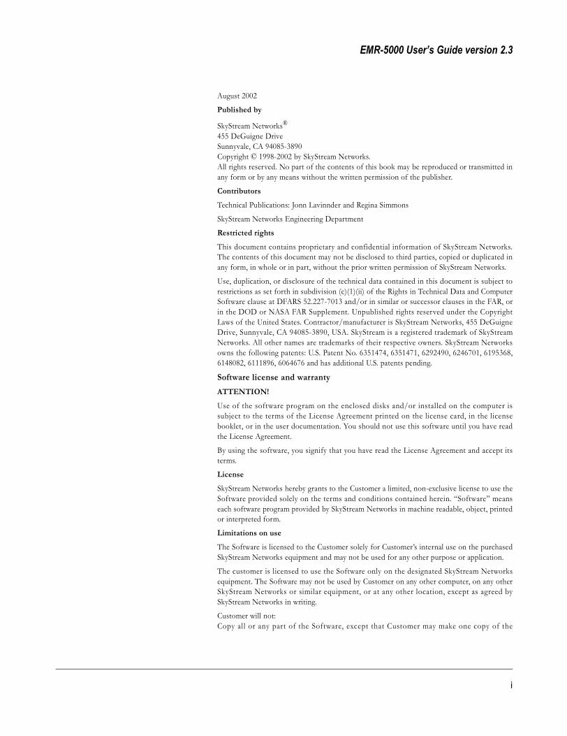
The following steps will walk you through connecting a PC directly to the EMRwith a serial null-modem cable giving you access to the Command Line Interfaceconfiguration page:
1 Mount the EMR in a 19-inch standard rack using the screws and bracketsprovided. (See separate installation sheet.)
2 Connect to the satellite receiver at the back of the EMR using coaxial cable.
3 Connect the SkyStream EMR to a PC via the serial null-modem cable.
4 Connect the power cord to the EMR and to an available power source.
5 Turn on the power switch found on the back of the EMR.
6 Once the EMR is on, start a HyperTerminal session to open a connection tothe EMR with the PC or workstation.
7 Configure HyperTerminal to 9600 baud, 8 bits, no parity, 1 stop (9600 N81)and set Flow control to “None.”
8 Enter the user name to log in, this will open the Command Line Interface(CLI). See Chapter 3, “First Time Logon.”
NOTE No password is required if none is assigned.For information on how to configure the SkyStream EMR using the CLI, seeChapter 4, “CLI Commands and Operation.”
13

SkyStream Networks
Crossover Cable Configuration (static IP)
The following components are required for the installation of the SkyStreamEMR with the Crossover cable (static IP) configuration:
Hardware Dependencies• Low Noise Block Converter (LNB) connected to the satellite receiver
• Satellite Receiver
• ISDN card (optional)
• Internal modem (optional)
• PC or workstation with a serial port.
Cables Required – (supplied by the user)• Crossover cable
• Coaxial cable for connecting to satellite receiver on the EMR
Software Requirements• Internet Web GUI
Crossover cable A network cable that crosses the transmit and receive lines. The crossover cable is used to connect hubs and switches together using standard MDI-X ports, which are already crossover ports. The crossover cable crosses the lines first so that after the MDI-X crosses the lines, they are effectively back to a non-crossed condition.
14 Hardware Specifications and Installation
EMR-5000 User’s Guide version 2.3
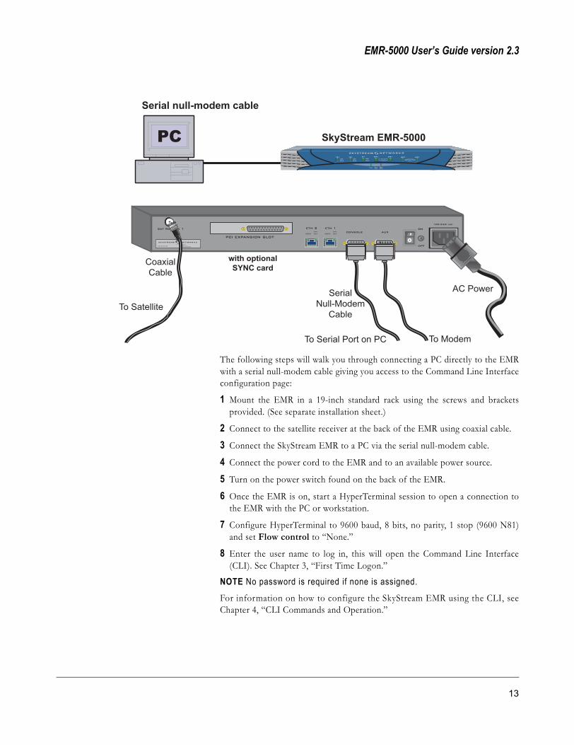
NOTE When using the internal modem, plug the phone line into LINE and usePHONE as a phone extension.The following steps will walk you through connecting a PC directly to the EMRwith an Ethernet crossover cable giving you access to the Web GUI:
1 Mount the EMR in an available 19-inch standard rack using the screws andbrackets provided. (See separate installation sheet.)
2 Connect to the satellite receiver at the back of the EMR using coaxial cable.
3 Connect the SkyStream EMR to a PC via a crossover network cable. (Youmust connect the cable to LAN 1 connector on the back of the EMR.)
4 Connect other end of crossover cable to the PC or workstation you are usingto connect to the EMR.
5 Connect the power cord to the EMR and an available power source.
6 Turn on the power switch found on the back of the EMR.
7 Enter the following IP address and subnet mask for the PC or workstationyou are using to connect to the EMR:
IP Address = 172.16.1.3Subnet mask = 255.255.255.0
This will allow you to connect to the EMR through the Web GUI.
NOTE Consult the appropriate Microsoft documentation for details on how toconfigure the IP address and subnet mask on the PC.
8 If the power light and LAN 1 LEDs on the front of the EMR panel are onthen the EMR is running. Enter the EMR’s IP address in the Web GUI’saddress field as follows: http://172.16.1.2
Default EMR IP Address: 172.16.1.2See Chapter 3, “First Time Logon.”
For more information on how to configure the EMR through the web interface,refer to Chapter 5, “Web GUI Configuration.”
15
SkyStream Networks
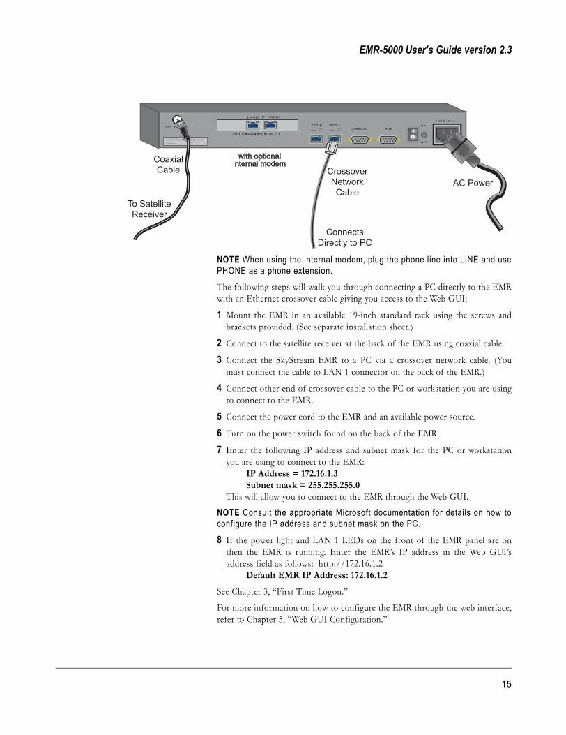
Network Hub Configuration(static IP)
The following components are required for the installation of the SkyStreamEMR with the Network hub (static IP) configuration:
Hardware Dependencies• Low Noise Block Converter (LNB) connected to the satellite receiver.
• Satellite Receiver
• Secondary Satellite Receiver (optional)
• PC or workstation with a serial port.
• Hub for network interface
Cables Required – (supplied by the user)• Network cable
• Coaxial cable for connecting to satellite receiver on the EMR
Software Requirements• Internet Web GUI
Network hub A central connecting device in a network that joins communications lines together in a star configuration.
Static IP address A permanent IP address that is assigned to a node in a TCP/IP network. Servers and routers are usually assigned static IP addresses, while client stations are often assigned dynamic IP addresses from a DHCP server each time they come online.
16 Hardware Specifications and Installation

EMR-5000 User’s Guide version 2.3
The following steps will walk you through connecting a PC directly to the EMRwith an Ethernet hub giving you access the Web interface:
1 Mount the EMR in a 19-inch standard rack using the screws and bracketsprovided. (See separate installation sheet.)
2 Connect to the satellite receiver at the back of the EMR using coaxial cable.
3 Connect the SkyStream EMR to the hub using a network cable. You must usethe LAN 1 connector.
4 Connect the power cord to the EMR and an available power source.
5 Turn on the power switch found on the back of the EMR.
6 Enter the following IP address and subnet mask for the PC or workstationyou are using to connect to the EMR:
IP Address = 172.16.1.3 Subnet mask = 255.255.255.0
This will allow you to connect to the EMR through the Web GUI.
NOTE Consult the appropriate Microsoft documentation for details on how toconfigure the IP address and subnet mask on the PC.
7 If the power light and LAN 1 LEDs on the front of the EMR panel are onthen the EMR is running. Enter the EMR’s IP address in the Web GUI’saddress field: http://172.16.1.2
Default EMR IP Address: 172.16.1.2
See Chapter 3, “First Time Logon.”
To configure the EMR and satellite receivers further, refer to Chapter 5, “WebGUI Configuration.”
17

SkyStream Networks
Network Hub Configuration (DHCP)
The following components are required for the installation of the SkyStreamEMR with the Network hub (DHCP) configuration:
Hardware Dependencies• Low Noise Block Converter (LNB) connected to the satellite receiver
• Satellite Receiver
• DHCP Server – (supplied by the user)
• PC or workstation
• Hub for network interface
Cables Required – (supplied by the user)• Ethernet cable
• Coaxial cable for connecting to satellite receiver on the EMR
Software RequirementsInternet Web GUI – (supplied by the user)
DHCP (Dynamic Host Configuration Protocol) Software that automatically assigns IP addresses to client stations logging onto a TCP/IP network. It eliminates having to manually assign permanent IP addresses. DHCP software typically runs in servers and is also found in network devices such as ISDN routers and modem routers that allow multiple users access to the Internet.
18 Hardware Specifications and Installation

EMR-5000 User’s Guide version 2.3
The following steps will walk you through connecting a PC directly to the EMRusing Ethernet and giving you access to the Web GUI:
1 Mount the EMR in a 19-inch standard rack using the screws and bracketsprovided. (See separate installation sheet.)
2 Connect to the satellite receiver coaxial cable(s) at the back of the EMR.
3 Connect the SkyStream EMR to the hub where the PC and the DHCP serverare connected. Make sure you connect the cable to LAN 2 port.
4 Connect the power cord to the EMR and to an available power source.
5 Turn on the power switch found on the back of the EMR.
6 Find the MAC address for the EMR’s LAN 2 Ethernet port. (Either on asticker on the back of the EMR or in additional documentation provided withthe EMR.)
7 Configure your DHCP server to recognize the EMR’s MAC address andautomatically assign a predetermined IP address that conforms to your localnetwork. If no DHCP server is found and this operation fails, then Ethernet 2will be assigned to 172.16.2.2.
8 If the power light and LAN 2 LED on the front of the EMR panel are on thenthe EMR is ready to be configured for data transfer. Enter the EMR’s IPaddress in the Web GUI’s address field.
For more information on how to configure the EMR through the web interface,refer to Chapter 5, “Web GUI Configuration.”
19

SkyStream Networks
Regulatory Compliance
Feature Standard Comments
Electromagnetic Interference (EMI)
FCC Class BEN 55024 (1998)EN 55022 (1995) Class AVCCI Class AFCC Part15 Sub part B Class ACISPR 22/85 Class A
Noise frequency range: 30 MHz to 1GHz
Immunity: Electrostatic Discharge
EN 61000-4-2IEC 1000-4-2
Discharges of ± 15kV with an air discharge probe on the receptacle cause no damage
Immunity: Radio Frequency Electromagnetic Field
EN 61000-4-3IEC 1000-4-3
With a field strength of 10 V/m rms, noise frequency ranges from 10 MHz to 1 GHz
Eye Safety IEC 825-1 Class 1
Safety EN 60950 Class 1
20 Hardware Specifications and Installation

EMR-5000 User’s Guide version 2.3
Replacing the backup battery
The lithium battery on the motherboard powers the real time clock (RTC) for upto 10 years in the absence of power. When the battery starts to weaken, it losesvoltage, and the system settings stored in CMOS RAM in the RTC may bewrong. Contact your customer service representative or dealer for a list ofapproved devices.
WARNING (for Customer Service trained technician)There is a danger of explosion if battery is incorrectly replaced. Replace onlywith the same or equivalent type recommended by the equipment manufacturer.Discard used batteries according to manufacturer’s instructions.
InstructionsThe following instructions should only be undertaken by a trained service person.1. Observe the standard safety
and ESD precautions.2. Open the chassis.3. Insert the tip of a small flat
bladed screwdriver, or equivalent, under the tab in the plastic retainer.
4. Gently push down on the screwdriver to lift the battery.
5. Remove the battery from its socket.
6. Dispose of the battery according to local ordinances.
7. Remove the new lithium battery from its package, and observe the correct polarity; insert it in the battery socket.
8. Close the chassis.
21

SkyStream Networks
22 Hardware Specifications and Installation

EMR-5000 User’s Guide version 2.3
Chapter 3: System Logon
23

SkyStream Networks
First Time LogonAccessing the SkyStream EMR happens in one of two ways. You can use either a command-line interface (CLI) or a Web GUI. In addition, you can access the CLI either through the serial port or through telnet via the Ethernet interface. The web interface is accessed via the Ethernet. The following sections walk you through the logon processes for the CLI or Web GUIs.
CLI Login If an Ethernet or a Web GUI connection is not available, you can configure the SkyStream EMR with the Command Line Interface (CLI) using the serial port connection, this is reviewed in “Basic Connections.”
SecurityThere are two levels of security/authentication in the EMR:
� emradmin —full privileges
� emruser —cannot change SMMP properties (PIDs and Ports)
TIP SkyStream recommends that only users familiar with the CLI format use the Command Line Interface.
Start Telnet from the management PC.
1 Click the Windows Start button.
2 Click Run.
3 In the Open box, type: telnet xxx.xxx.xxx.xxx(and the IP Address of the EMR you are connecting to)
4 Click OK.
5 Type at EMR5000 login: emradmin
NOTE No password is required at this time, just press Enter.
TIP To look at more lines than can be seen, when typing CLI commands, right-click the Command Prompt Window title bar and click Properties. Click Layout tab and change page Buffer Width to 90 and Height to 70. Make sure that “Let the system position the window” is checked. This should allow you to use scroll bars to view the lines of text.
24 System Logon

EMR-5000 User’s Guide version 2.3
Web GUI Login Start the Web GUI from the management PC by typing the EMR’s IP address in the Web GUI’s address field.
SecurityThere are two levels of security/authentication in the EMR:
� emradmin —full privileges
� emruser —cannot change SMMP properties (PIDs and Ports)
1 Click File from the Menu Bar.
2 Click Open...
3 In the Open box, type: (EMR IP address)
TIP After you have logged on for the first time, a good practice is to change the password. See Chapter 4, “Command Definitions—passwd.” ALSO See: Chapter 5, “Maintenance—Change Password.”
4 Click one of the buttons (Statistics, Configuration, Maintenance, or Diagnostics) on the left side of the page. This will open a Network Password dialog box.
5 In User Name type: emradmin.
NOTE No password is required at this time.
6 Click OK.
25

SkyStream Networks
26 System Logon
EMR-5000 User’s Guide version 2.3
Chapter 4: CLI Commands and Operation
27

SkyStream Networks
Command Line InterfaceCLI Basics This chapter covers the basic operation and commands of the Command Line
Interface (CLI). After reading this chapter, you will be able use the CLI toconfigure and manage the EMR.
You can access the SkyStream EMR’s command line interface through a Telnetor console (serial port) connection. Accessing the command line interface isreferred to as a CLI session.
When you establish a CLI session, commands within the EMR’s CLI are in a treestructure. To configure the EMR, you need to understand how to navigate theCLI tree structure. The following section walks you through navigating withinthe CLI tree. With the help of the question mark (?) and “Show” functions, youwill learn how to determine where you are in the tree, and what functions andsubcommands are available.
Depending on the position within the tree structure, you will have access todifferent command options. Once in a given configuration branch, you mayenter the system level configuration commands that apply to that particularlevel. In addition, the command prompt changes to reflect the position withinthe tree structure to assists with navigation. This allows for easy reference withinthe tree structure when in configuration mode.
To start a CLI session, see Chapter 3, “CLI Login.”
To list the main nodes available at the CLI level, type a question mark (?) at theprompt and hit Enter. Typing “?” at the prompt will display the fol lowing commands: show, no,ifconfig, netstat, ping, reboot, route, passwd, config, maintenance, diag, andstats.
When you combine “show” with the question mark (?), the system displays allthe subcommands that you can view. For example, when you type “Show cli-tree,” the system displays all nodes, subcommands, and functions of the “cli-tree.”
Type “show cli-tree” to display the CLI tree structure:
This command will display all the root nodes and root subcommands of “cli-tree” (see Command Definitions).
You can use the “?” with “show” subcommands when there are functions belowthe subcommands at this level; for example, “show interface ?”. This will displaythe interfaces available.
NOTE Type a space between “show” and “?.”
28 CLI Commands and Operation

EMR-5000 User’s Guide version 2.3
Navigation in config-mode
The CLI has a special configuration mode, which allows you to configureindividual subsystems. By typing “config” at the prompt, you wil l enterconfiguration mode. The prompt will then change to:
[config-mode]#To review what functions are available, enter a question mark (?) at the prompt.
Type “?” at the [config-mode]# prompt:
The following functions will display: pref, interface, active_macs1, active_pids1,active_fkcas1, skycast, skycast_rule, skynat1, snmp, tcpX, and turbointernet-vpn.
At the [config-mode]# prompt, enter the next node you wish to access; forexample, when you enter interface, the command prompt changes to [config-mode interface]#. To access the nodes at the next level, enter a question mark(?) at the prompt.
Type “?” at the [config-mode interface]# prompt:
Displays the following interfaces: satrx1, eth1, eth2, ppp, isdn (optional) andsync (optional).
At the [config-mode interface]# prompt, enter the next node you wish toaccess. For example, when you enter satrx1 {, the command prompt changes to[config-mode interface satrx1]#. To display the options at the next level, enterquestion mark (?) at the prompt.
NOTE The user must type “{” after the node to configure. If not, CLI will return“{ <CR>” meaning that the user must type “{“ followed by a carriage return(Enter).Type “?” at the [config-mode interface satrx1]# prompt:
The satellite-configuration option list appears, which shows all the configurableoptions available on the interface (see Command Definitions).
Configuration Values
Each configuration option has a value that you can enter. For example, the “String”values on the “IfStatus” options allows you to enter a rule. The “IP Address” issimply the IP address being assigned to the Ethernet connection of the satellitereceiver. The “Integer” value is a number for setting the specific option.
TIP When typing commands in CLI, after a few keystrokes, use the TAB key to complete a command automatically.
To set the satrx1 to 10 Msymbols, at the prompt, type “symbolrate 10.” It shouldlook like this:
[config-mode interface satrx1]# symbolrate 10NOTE To return to [config-mode], type “}” to close the current node or, to goto the CLI prompt, type “exit.”
Conventions: A convention used throughout this User Guide is the use of“<>” (greater than and lesser than brackets)—brackets enclose keystrokeinstructions. For example: <filename> means, type the name of a file, or <CR>means, press “Enter” i.e., a Carriage Return.
29

SkyStream Networks
Command DefinitionsThe following section defines all the commands used by CLI.
root
Command Type: ?
Description Shows all top-level root nodes
Range (Nodes at top-level)
Example show Show commands to display informationno Disable commandsifconfig Show active interface statusnetstat Show Networking statisticsping Ping the specified hostreboot Reboot the emr boxroute Show IP routing tablepasswd Update user passwordconfig Enter the configuration modemaintenance Maintenance command treediag Diagnostics command treestats Root of the statistics command
show
Command Type: show ?
Description Shows all show subcommands
Range (All show subcommands)
Example cli-tree Display the CLI treerunning-config Display the current configurationinterface Root of the show interface commandsactive_pids Display active PIDs listactive_macs Display active MACs listactive_fkcas Display active fkcas listskycast_rules Display SkyCast rulesskynat_rules Display SkyNAT rulesskynpt_rules Display SkyNPT rulestcpX Display TCP Acceleration settingversion Show system version informationturbointernet-vpn Display Turbo Internet setting
30 CLI Commands and Operation

EMR-5000 User’s Guide version 2.3
show cli-tree
Command Type: show cli-tree
Description Shows all CLI tree root nodes and root subcommands
Range (All show subcommands)
NOTE ISDN, Sync, and TCP Acceleration are optional features, the CLIcommands for these options will only be available if you have these options.
Example root -> show no ifconfig netstat ping reboot route passwd config maintenance diag statsroot show -> cli-tree running-config interface active_pids active_macs active_fkcas skycast_rules skynat_rules skynpt_rules tcpX version turbointernet-vpnroot show cli-tree ->root show running-config ->root show interface -> satrx1 eth1 eth2 ppp isdn syncroot show interface satrx1 ->root show interface eth1 ->root show interface eth2 ->root show interface ppp ->root show interface isdn ->rrot show interface sync ->root show active_pids ->root show active_macs ->root show active_fkcas ->root show skycast_rules ->root show skynat_rules ->root show skyntp_rules ->root show tcpX ->root show version ->root show turbointernet-vpn ->root no ->root ifconfig ->root netstat ->root ping ->root reboot ->root route ->root passwd ->root date ->root timezone ->root config ->root maintenance -> kernel_list boot_mode sw_upgrade key_upgrade reset_counter configuration tcpXmoderoot maintenance kernel_list ->root maintenance boot_mode ->root maintenance sw_upgrade ->root maintenance key_upgrade ->root maintenance reset_counter -> satrx1root maintenance reset_counter satrx1 ->root maintenance configuration -> list wrt del load default factoryroot maintenance configuration list ->
31

SkyStream Networks
root maintenance configuration wrt ->root maintenance configuration del ->root maintenance configuration load ->root maintenance configuration default ->root maintenance configuration factory ->root maintenance tcpXmode ->root diag -> run view upload syslogroot diag run ->root diag view ->root diag upload ->root diag syslog ->root stats -> satrx1 eth1 eth2 tcpX ppp isdn turbointernet-vpn syncroot stats satrx1 ->root stats eth1 ->root stats eth2 -> root stats tcpX ->root stats ppp ->root stats isdn ->root stats turbointernet-vpn ->root stats sync ->
show running-config
Command Type: show running-config
Description Shows what interfaces are running
Range (All configurations running)
Example pref {
PidInputStyle hexTelnet enableHTTP enableRouterMode enableBoostLevel disablePidRateMonitoring enableConsoleLogView enableFECMode autoPromiscuousMode disableMACForwarding ethernet-1TCPProxy disableSMMPCtrlPidStatus lockSMMPDataPidStatus lockSMMPCtrlPortStatus lockSMMPDataPortStatus lockSMMPAutoDiscPortStatus lockSMMPCtrlAddrMCastStatus lockSMMPDataAddrMCastStatus lockSMMPCtrlPid 0X1FF5SMMPDataPid 0X1FF6SMMPCtrlPort 20000SMMPDataPort 20001SMMPAutoDiscPort 20002
32 CLI Commands and Operation

EMR-5000 User’s Guide version 2.3
SMMPCtrlMCastAddr 230.10.10.10SMMPDataMCastAddr 230.10.10.11
}
interface satrx1 {
IfStatus up
IPAddr 200.100.100.100
SubnetMask 255.255.255.0
SatInFreq 0.00
SymbolRate 20.00
Polarization disable
LNBMode none
LBANDFreq 1176.00
LNBLowFreq 0.00
LNBHighFreq 0.00
ViterbiRate 1/2
22KHzSwitch disable
}
interface eth1 {
IfStatus up
IPAddr 10.1.1.2
SubnetMask 255.255.255.0
DHCP disable
}
interface eth2 {
IfStatus up
IPAddr 192.168.4.113
SubnetMask 255.255.255.0
DHCP enable
}
interface ppp {
}interface ppp server {
PhoneNum
Username
Password
DebugStatus off
ExpectSendEntry1 -,-
ExpectSendEntry2 -,-
ExpectSendEntry3 -,-
ExpectSendEntry4 -,-
ExpectSendEntry5 -,-
}
interface ppp network {
UsePeerDefaultRoute yes
MaxRecvUnit 1500
MaxRecvUnit 1500
ConnectTimeout 120
}
interface ppp hardware {
33

SkyStream Networks
LineSpeed 57600
HwFlowControl enable
}
interface ppp modem {
InitString ATE0V1Q0&D2
DialString ATDT}
interface ppp {
}interface isdn server {
PhoneNumber Not Set
UserName Not Set
Password Not Set
}
interface isdn ppp {
UseThisAsDefaultRoute yes
VJHeaderCompression enable
BChannel twochannels
MRU 2000
MTU 1500
IPAddressNegotiation enable
RequestedIPAddress 0.0.0.0
RequestedRemoteIPAddress 0.0.0.0
}
interface isdn line {
DChannelProtocol ni1
MSNEAZ1 Not Set
MSNEAZ2 Not Set
SPID1 Not Set
SPID2 Not Set
interface sync {
PID 0XFFFF
SerialBitShift LSB
Speed 0
}
active_macs1 {
01:00:5e:00:00:00
}
active_pids1 {
0X1FF5
}
active_fkcas1 {
}
skycast {
Status enable
DefaultOrgDestIPAddr 224.0.0.0
DefaultNetmask 240.0.0.0
DefaultTTL 15
34 CLI Commands and Operation

EMR-5000 User’s Guide version 2.3
DefaultAction fwd-if-listner
DefaultFwdOutNetworkIf eth1
}
skycast_rule {
224.6.6.6 224.6.6.6 2 fwd eth1 255.255.255.255224.6.1.24 224.6.1.4 2 fwd eth1 255.255.255.255
}
skynat1 {
nat_status disable
npt_status disable
}
skynat1 skynat_rules {
}
skynat1 skynpt_rules {
}
snmp mib2sys {
SysContact [email protected]
SysLocation Sunnyvale
}
snmp access {
public rw
}
snmp trap {
192.168.4.161 public
}tcpX {
TransparentProxy disable }
tcpX network server {
PrimaryRemoteServerAddr 192.168.4.177
PrimaryRemoteServerPort 2915
SecondaryRemoteServerAddr 0.0.0.0
SecondaryRemoteServerPort 2913
POP3ServerAddr 0.0.0.0
POP3ServerPort 110
SMTPServerAddr 0.0.0.0
SMTPServerPort 25
NNTPServerAddr 0.0.0.0
NNTPServerPort 119
}
tcpX network client {
HTTPListenPort 9090
POP3ListenPort 110
FTPListenPort 9091
SSLListenPort 9092
SMTPListenPort 25
NNTPListenPort 119
}
tcpX compression {
CompressionStatus disabled
35

SkyStream Networks
CompressionLevel 1
HTTPCompressionStatus no
FTPCompressionStatus no
}
tcpX compression fileext {
txt
doc
html
htm
bmp
}
tcpX userport {192.22.23.24 23 333
}
turbointernet-vpn pptp {
ServerIPAddress 192.168.4.187
Username 1234
Password 1234
SatelliteMacFilter pppaddress
}
turbointernet-vpn ipsec conf {
GatewayIPAddress 192.168.4.186
IPSecMode tunnelmode
RemoteSubnet 0.0.0.0
RemoteSubnetMask 192.0.0.0
LocalSubnet 0.0.0.0
LocalSubnetMask 240.0.0.0
}
turbointernet-vpn ipsec ike {
EncryptionAlgorithm 3des
AuthAlgorithm hmacmd5
DiffHellman group2
AuthMode sharedsecret
SharedSecret 1234
}
turbointernet-vpn ipsec security {
UseAuthHeader UnKnownEnumValue
AHAuthenticationAlgorithm hmacmd5
UseESP UnKnownEnumValue
ESPEncryptionAlgorithm 3des
ESPAuthenticationAlgorithm hmacmd5
ReplaceKeyEverySeconds 28800
ReplaceKeyEveryKBs 100000
}
turbointernet-vpn connection {
ConnectionUsed ipsec
InitiateConnection automatic
Status IPSec Disconnected, PPTP Disconnected
}
36 CLI Commands and Operation

EMR-5000 User’s Guide version 2.3
turbointernet-vpn advanced {
NATApplied ethernet-1
MACPrefix 1234
}
show interface
Command Type: show interface ?
Description Shows interface settings
Range (EMR interface cards)
Example satrx1 Display Satellite Receiver Interface 0 settingeth1 Display Network Interface 0 settingeth2 Display Network Interface 1 settingppp Display PPP setting
isdn Display ISDN settingsync Display Sync Interface setting
show interface satrx1
Command Type: show interface satrx1
Description Shows interface satrx1 settings
Range (see [config-mode] interface satrx1)
Example SatRx1
current settings
SatRxIfStatus :up
SatRxIPAddr :200.100.100.100
SatRxSubnetMask :255.255.255.0
SatMACAddr :00:30:1d:00:04:f6
SatInFreq(GHz) :0.00
LBANDFreq(MHz) :1176.00
SymbolRate(MSym/sec) :20.00
Polarization :disabled
ViterbiRate :7/8
SignalLockStatus :LOCK
DataLockStatus :LOCK
MPELockStatus :UNLOCK
SignalStrength(%) :56
22KHzSwitch :disable
LNBMode :none
37

SkyStream Networks
LNBLowFreq(GHz) :N/ALNBHighFreq(GHz) :N/A
LNBOffset(MHz) :0.09
Eb/N0 (dB) :10.50
QPSKBER :0.00
ViterbiBER :0.00
ReedSolomonCError :0
ReedSolomonUCError :0
show interface eth1
Command Type: show interface eth1
Description Shows interface eth1 settings
Range (see [config-mode] interface eth1 or eth2)
Example Eth1current settings
IfStatus :upIPAddr :192.168.100.104SubnetMask :255.0.0.0MACAddr :00:30:1d:00:04:3dDHCP :disable
show interface eth2
Command Type: show interface eth2
Description Shows interface eth2 settings
Range (see [config-mode] interface eth1 or eth2)
Example Eth2current settings
IfStatus :upIPAddr :192.168.200.104SubnetMask :255.255.255.0MACAddr :00:30:1d:00:04:3cDHCP :disable
show interface ppp
Command Type: show interface ppp
Description Shows interface ppp settings
38 CLI Commands and Operation

EMR-5000 User’s Guide version 2.3
Range (see [config-mode] interface ppp)
Example PPP
current PPP Interface settings
PPPStatus :disable
DialMode :manual
ConnectionStatus :disconnected
IfStatus :down
current ISP/Remote PPP Server settings
PhoneNumber :Not Set
UserName :Not Set
Password :Not Set
DebugOn :off
ExpectSendEntry1 :-,-
ExpectSendEntry2 :-,-
ExpectSendEntry3 :-,-
ExpectSendEntry4 :-,-
ExpectSendEntry5 :-,-
current Network setup
UsePeerDefaultRoute :yes
MaxRecvUnit (MRU) :1500
MAXTranUnit (MTU) :1500
ReqLocalIPAddr :0.0.0.0
ReqRemoteIPAddr :0.0.0.0
current Hardware settings
LineSpeed :57600
HWFlowControl :enable
current Modem settings
InitString :ATE0V1Q0&D2
DialString :ATDT
show interface isdn (optional)
Command Type: show interface isdn
Description Shows isdn interface settings
Range (see [config-mode] interface isdn)
Example ISDNInterface settings
MasterStatus : ConnectedDialMode : Manual
39

SkyStream Networks
IfStatus : UpISP/Remote ISDN Server Setup
PhoneNumber :Not Set
UserName :Not Set
Password :********
ISDN-PPP Setup
UseThisAsDefaultRoute :Yes
VJHeaderCompression :Enabled
BChannel :One Channel
MRU :2000
MTU :1500
IPAddressNegotiation :Enabled
RequestedIPAddress :0.0.0.0
RequestedRemoteIPAddress :0.0.0.0
ISDN Line Settings
DChannelProtocol :NI1
MSNEAZ1 :Not Set
MSNEAZ2 :Not Set
SPID1 :121123
SPID2 :1234567890
show interface sync (optional)
Command Type: show interface sync
Description Shows sync interface settings
Range (see [config-mode] interface sync)
Example Sync
current settings
PID :0XFFFF
SerialBitShift :LSB
Speed(bps) :2
Media Type :X.21
Protocol :HDLC
Link Status :Up
40 CLI Commands and Operation

EMR-5000 User’s Guide version 2.3
show active_pids
Command Type: show active_pids
Description Shows active PID numbers entered by the user
Range (PIDs in decimal or hexadecimal)
Example Pid list1
----------------------
Pid Num | Pid Type
----------------------
34 strmUnknown35 strmUnknown36 strmUnknown48 strmUnknown
show active_macs
Command Type: show active_macs
Description Shows additional active MAC addresses for satellite receivers
Range (Shows active MAC addresses entered by user)
Example Promiscuous Mode : disable
MAC list1
------------------
MAC Address list
------------------
00:20:34:59:00:20
show active_fkcas
Command Type: show active_fkcas
Description Shows active fixed keys
Range (Shows active fixed keys entered by user)
Example fkcas list1
41

SkyStream Networks
------------------------------------------
Pid Num | Key | Parity
------------------------------------------
24 12-00-00-20-34-59-00-20 even
show skycast_rules
Command Type: show skycast_rules
Description Shows each SkyCast rule in the following format: original destination IP address,new destination IP address, TTL, packet action, netmask IP address, packetsreceived, and packets sent. to Ethernet 1 and Ethernet 2.
Range (see [config-mode] skycast_rules)
Example skycast status: enable
--------------------------------------------------------------------------------
OrgIPAddr|NewIPAddr|TTL|Action |eth|NetMask|PktRecv|PktProc|PktToEth1|PktToEth2
--------------------------------------------------------------------------------
224.6.6.6 |224.6.6.6 |20 |fwdiflst|1 |255.0.0.0| 0 |0 |0 |0 |0
show skynat_rules
Command Type: show skynat_rules
Description Shows SkyNAT: original destination IP address, new destination IP address,Time-To-Live, Action, Netmask IP address, packets processed, and packets sent.
Range (see [config-mode] skynat1)
Example nat1 status: Enable
SkyCast The SkyStream system used for IP Multicast Management.
SkyNAT EMR application used to support packet translation of incoming data from satellite for address translation, protocol translation, and TTL translation.
42 CLI Commands and Operation
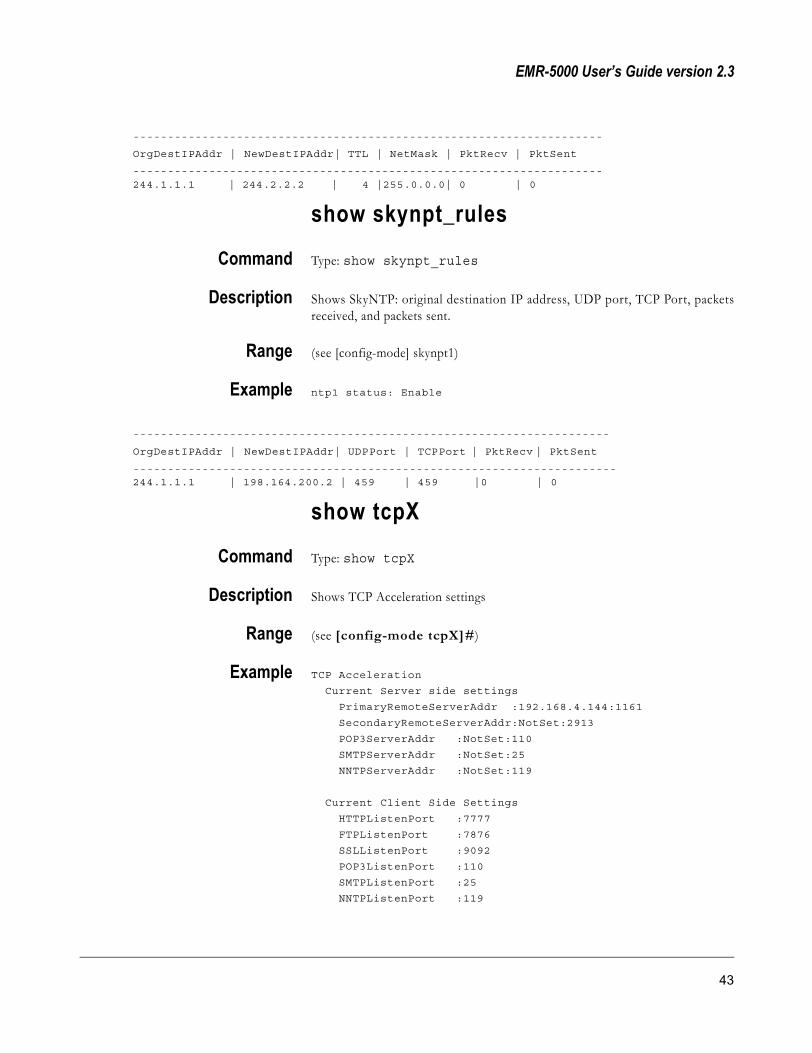
EMR-5000 User’s Guide version 2.3
--------------------------------------------------------------------
OrgDestIPAddr | NewDestIPAddr| TTL | NetMask | PktRecv | PktSent
--------------------------------------------------------------------244.1.1.1 | 244.2.2.2 | 4 |255.0.0.0| 0 | 0
show skynpt_rules
Command Type: show skynpt_rules
Description Shows SkyNTP: original destination IP address, UDP port, TCP Port, packetsreceived, and packets sent.
Range (see [config-mode] skynpt1)
Example ntp1 status: Enable
---------------------------------------------------------------------
OrgDestIPAddr | NewDestIPAddr| UDPPort | TCPPort | PktRecv | PktSent
----------------------------------------------------------------------244.1.1.1 | 198.164.200.2 | 459 | 459 |0 | 0
show tcpX
Command Type: show tcpX
Description Shows TCP Acceleration settings
Range (see [config-mode tcpX]#)
Example TCP Acceleration
Current Server side settings
PrimaryRemoteServerAddr :192.168.4.144:1161
SecondaryRemoteServerAddr:NotSet:2913
POP3ServerAddr :NotSet:110
SMTPServerAddr :NotSet:25
NNTPServerAddr :NotSet:119
Current Client Side Settings
HTTPListenPort :7777
FTPListenPort :7876
SSLListenPort :9092
POP3ListenPort :110
SMTPListenPort :25
NNTPListenPort :119
43

SkyStream Networks
Current User Defined Service Settings
-----------------------------------------
ServerAddress | ServerPort | ClientPort
-----------------------------------------
200.200.200.200 | 8888 | 9999
Current Compression Settings
CompressionStatus:Disabled
CompressionLevel :1
HTTPCompression :No
FTPCompression :No
CompressedFileExt:txt,
bmp,
doc,
PPP
Current General Info
TCPAccModeStatus :Enabled
MaxTCPConn :1000
TransparentProxy :Disabled
show version
Command Type: show version
Description Shows Bitstream file, current kernel version of EMR software running, numberof interfaces, and Field Programmable Gate Array version.
Range (All version numbers)
Example Current Running Kernel Version : EMR.17.06
Software Package : TCP Acceleration
Software Build Date : Sep 8 01:15:07 CDT 2001
System Uptime : 0 days, 01:13
Number of Satrx Interface : 1
Number of Ethernet Interface : 2
Total SDRAM : 128 MB
Mainboard Version : EMR5000
Boot Version : 1.17
System Firmware Version : 2001/04/27:15:23:42
Tuner Firmware Version : 2001/02/06:17:16:26
show turbointernet-vpn
Command Type: show turbointernet-vpn
44 CLI Commands and Operation

EMR-5000 User’s Guide version 2.3
Description Shows Turbo Internet/VPN settings
Range (All version numbers)
Example TurboInternet/VPN
current Connection Method
Status :IPSec Disconnected ,PPTP Disconnected
ConnectionUsed :PPTP
InitiateConnection :Upon Request (Manually)
current PPTP settings
ServerIPAddress :64.165.192.142
UserName :administrator
Password :******
SatMACFiltering :PPP Address (Encrypted over DVB)
Advanced Options settings
NATApplied :Ethernet-1
MACPrefix :0000
no
Command 1 Type: no
Description Use the no command to delete configuration values under the following foursections; active pids, active macs, skycast rules, and skynat rules.
Range ( active configuration values)
Example (see [config-mode active_pids1]#) type: no 0x10
(see [config-mode active_macs1]#) type: no 00:00:ce:aa:02:b7
( s e e [c onf ig - mode s k yc as t_ r u le s ] # ) t y p e : no 234.231.10.1234.231.10.1 237 fwd-if-listener eth1 255.255.255.255
(see [config-mode skynat_rules]#) type: no 244.1.1.1 244.2.2.2 4255.0.0.0 0 0
ifconfig
Command Type: ifconfig
Description Shows all interface information
45

SkyStream Networks
Range (All ifconfig information)
Exampleeth1 Link encap:Ethernet HWaddr 00:30:1D:00:09:E9
inet addr:192.168.4.187 Bcast:192.168.4.255 Mask:255.255.255.0
UP BROADCAST RUNNING MULTICAST MTU:1500 Metric:1
RX packets:9542660 errors:9 dropped:9 overruns:0 frame:13
TX packets:19700 errors:0 dropped:0 overruns:0 carrier:19441
collisions:0 txqueuelen:1000
Interrupt:9 Base address:0xffe0
eth2 Link encap:Ethernet HWaddr 00:30:1D:00:09:E8
inet addr:172.16.2.2 Bcast:172.16.2.255 Mask:255.255.255.0
UP BROADCAST RUNNING MULTICAST MTU:1500 Metric:1
RX packets:2969131 errors:0 dropped:0 overruns:0 frame:0
TX packets:15155 errors:0 dropped:0 overruns:11414 carrier:11414
collisions:0 txqueuelen:100
Interrupt:28
satrx1 Link encap:Ethernet HWaddr 00:30:1D:00:09:EA
inet addr:10.1.1.2 Bcast:10.1.1.255 Mask:255.255.255.0
UP BROADCAST RUNNING MULTICAST MTU:1500 Metric:1
RX packets:644 errors:0 dropped:0 overruns:0 frame:0
TX packets:644 errors:0 dropped:0 overruns:0 carrier:0
collisions:0 txqueuelen:100
lo Link encap:Local Loopback
inet addr:127.0.0.1 Mask:255.255.0.0
UP LOOPBACK RUNNING MTU:3856 Metric:1
RX packets:194 errors:0 dropped:0 overruns:0 frame:0
TX packets:194 errors:0 dropped:0 overruns:0 carrier:0
collisions:0 txqueuelen:0
ppp1 Link encap:Point-to-Point Protocol
inet addr:200.100.99.100 P-t-P:200.100.99.99 Mask:255.255.255.0
UP POINTOPOINT RUNNING NOARP MTU:1500 Metric:1
RX packets:10 errors:0 dropped:0 overruns:0 frame:0
TX packets:17 errors:0 dropped:0 overruns:0 carrier:0
collisions:0 txqueuelen:30
sl0 Link encap:Serial Line IP
UP POINTOPOINT RUNNING NOARP MULTICAST MTU:1500 Metric:1
RX packets:0 errors:0 dropped:0 overruns:0 frame:0
TX packets:0 errors:0 dropped:0 overruns:0 carrier:0
collisions:0 txqueuelen:10
46 CLI Commands and Operation

EMR-5000 User’s Guide version 2.3
netstat
Command Type: netstat
Description Shows all active network connection information (for more information on thenetstat command, see Appendix A: Command Definitions)
Range (All netstat information)
ExampleActive Internet connections (w/o servers)Proto Recv-Q Send-Q Local Address Foreign Address Statetcp 0 0 192.168.4.163:telnet 192.168.4.181:2406 ESTABLISHEDtcp 0 126 192.168.4.163:telnet 192.168.6.102:4132 ESTABLISHEDtcp 0 0 1.1.2:telnet 10.1.1.1:1077 ESTABLISHEDtcp 0 0 10.1.1.2:telnet 10.1.1.1:1079 ESTABLISHEDtcp 0 0 10.1.1.2:telnet 10.1.1.1:socks ESTABLISHEDtcp 0 0 10.1.1.2:telnet 10.1.1.1:1081 ESTABLISHEDActive UNIX domain sockets (w/o servers)Proto RefCnt Flags Type State I-Node Pathunix 3 [ ] DGRAM 7107 /dev/logunix 2 [ ] DGRAM 7110unix 2 [ ] STREAM 62unix 2 [ ] DGRAM 45
ping
Command 1 Type: ping (see Help)
Description Sends ICMP ping packets to a specified address (for more information on theping command, see Appendix A: Command Definitions).
Range (All IP addresses on network)
Example usage: ping [-LRdfnqrv] [-c count] [-i wait] [-l preload] [-p pattern] [-s packetsize] [-t ttl] [-I interface address] host
NOTE At the prompt, type the string of parameters separated with a space.
Command 2 Type: ping 192,168.100.70
Example PING 192.168.100.70 (192.168.100.70): 56 databytes64 bytes from 192.168.100.70:icm_seq=0ttl=128 time=1.6 ms
NOTE To stop PING command, type CTRL+C.
47

SkyStream Networks
reboot
Command Type: reboot
Description Reboots system
Range (EMR)
Example You will be prompted “reboot: Are you sure you want to reboot? (yes/no).”
route
Command Type: route
Description Shows IP routing information (for more information on the route command, seeAppendix A: Command Definitions)
Range (All active network destinations)
ExampleKernel IP routing tableDestination Gateway Genmask Flags Metric Ref Use Iface192.168.4.0 0.0.0.0 255.255.255.0 U 0 0 0 eth110.1.1.0 10.1.1.2 255.255.255.0 U 0 0 0 eth0200.100.10.0 0.0.0.0 255.255.255.0 U 0 0 0 etnr0224.0.0.0 0.0.0.0 240.0.0.0 U 0 0 0 eth0default 192.168.4.254 0.0.0.0 UG 0 0 0 eth1
passwd
Command Type: passwd
Description Prompts to change password. Type in new password and press Enter. You willbe prompted to re-type the password again.
Range (Type a string)
Example Changing password for user cli.
New UNIX password:Retype new UNIX password:
After retyping the new password correctly, the following message is displayed: passwd: all athentication tokens updated successfully.
48 CLI Commands and Operation

EMR-5000 User’s Guide version 2.3
date
Command 1 Type: date
Description Press enter and it will display the current date and time.
Example Tues Jul 16 14:22:00 PDT 2002
Command 2 Type: date 071613002002
Description Sets the date to July 16th 2002 1:00 P.M. date command modifies system timeand hardware clock.
Range (24 hour clock)
timezone
Command 1 Type: timezone
Description Press enter and it will display the current timezone.
Example America/Los_Angeles
Command 2 Type: timezone -l
NOTE Use the lowercase letter ‘l” not the number “1”.
Description Press enter and it will lists available timezones.
Range (Country/City—see list)
Example Africa/AbidjanAfrica/AccraAfrica/Addis_AbabaAfrica/AlgiersAfrica/AsmeraAfrica/BamakoAfrica/Bangui
Command 3 Type: timezone US/Pacific
Description Press enter and it will set new timezone.
49

SkyStream Networks
configIn config mode, there are three formats for entering values:
1 Attribute + value
2 Value only
3 String of values
Each command will give you an example of which format to use.
Command 1 Type: config
Description Changes prompt to config-mode
Command 2 In [config-mode]# type: ?
Description Shows all [config-mode]# subcommands
Range (All [config-mode]# subcommands)
Example pref preferences configuration node interface Interface configurationactive_macs1 Active MAC list for Satellite Receiver 1active_pids1 PID list for Satellite Receiver 1active_fkcas1 FKCas list for Satellite Receiver 0skycast Skycast configuration nodeskycast_rule SkyCast rule listskynat1 Skynat configuration node
snmp snmp settings
tcpX TCP Acceleration configuration node
turbointernet-vpn Turbo Internet/VPN Configuration Node
TIP To delete a parameter for active_pids1, active_macs1, active_fkcas1, or skynat_rule1, at the applicable prompt, type “no” and then the parameter. Remember to type “{“ to open the node for configuration.
NOTE When changing the attributes of a list such as skycast_rules,active_macs1, active_pids1, active_fkcas1, and skynat_rule1, you must enterthe parameters as a string. When editing the string, type the whole correctedstring at the appropriate prompt and CLI will make the change. At the CLIprompt, type show running-config to check it.
50 CLI Commands and Operation

EMR-5000 User’s Guide version 2.3
[config-mode] pref
Command 1 In [config-mode]# type: pref {
Description Changes to [config-mode pref]
Command 2 In [config-mode pref]# type: ?
Description The preferences list appears, which shows configurable system parameters. Eachcommand is a toggle between a pair of parameters.
Range (see list)
Example Attribute listPidInputStyle dec | hexTelnet disable | enableHTTP disable | enableRouterMode disable | enableBoostLevel disable | enablePidRateMonitoring disable | enableConsoleLogView disable | enableFECMode auto | manualPromiscuousMode disable | enable MACForwarding ethernet-1 | ethernet-2TCPProxy disable | enable SMMPCtrlPidStatus lock | unlock
SMMPDataPidStatus lock | unlock
SMMPCtrlPortStatus lock | unlock
SMMPDataPortStatus lock | unlock
SMMPAutoDiscPortStatus lock | unlock
SMMPCtrlAddrMCastStatus lock | unlock
SMMPDataAddrMCastStatus lock | unlock
SMMPCtrlPid PidValue
SMMPDataPid PidValue
SMMPCtrlPort Integer(1 .. 65535)
SMMPDataPort Integer(1 .. 65535)
SMMPAutoDiscPort Integer(1 .. 65535)
SMMPCtrlMCastAddr IP Address (A.B.C.D)
SMMPDataMCastAddr IP Address (A.B.C.D)
Values
� PidInputStyle: Type “dec” or “hex” to toggle between decimal or hexadecimalparameters.
� Telnet: Type “disable” or “enable” to turn Telnet on or off.
� HTTP: Type “disable” or “enable” to turn HTTP on or off.
51

SkyStream Networks
� RouterMode: Type “disable” or “enable” to turn RIP V1on or off. For moreinformation, see Chapter 5, Configuration—Static Routes.
� BoostLevel: Type “enable” to boost the polarization voltage by one-volt.
� PidRateMonitoring: Type “enable” to see the Bit/rate in PID Selection, and“disable” Router Mode (Decrement TTL) if you don’t want TTL to decrement.
� ConsoleLogView: Type “enable” to have the log messages to display the on thepage.
� FECMode: Type “auto” or “manual.” For more information, see Chapter 5,Maintenance—Advanced Preferences.
� PromiscuousMode: Type “disable” or “enable.” For more information, seeChapter 5, Configuration—MAC Address Selection.
� MACForwarding: Type “ethernet-1” or “ethernet-2.”
� TCPProxy: Type “disable” or “enable” if you want to forward data from a clientto a server via TCP.
� SMMPCtrlPidStatus: Type “lock” or “unlock” to allow or block a PID beingentered through the SMMPCtrlPid command.
� SMMPDataPidStatus: Type “lock” or “unlock” to allow or block a PID beingentered through the SMMPDataPid command.
� SMMPCtrlPortStatus: Type “lock” or “unlock” to allow or block a PID beingentered through the SMMPCtrlPort command.
� SMMPDataPortStatus: Type “lock” or “unlock” to allow or block a PID beingentered through the SMMPDataPort command.
� SMMPAutoDiscPortStatus: Type “lock” or “unlock” to allow or block a PIDbeing entered through the SMMPAutoDiscPort command.
� SMMPCtrlAddrMCastStatus: Type “lock” or “unlock” to allow or block aPID being entered through the SMMPCtrlMcastAddr command.
� SMMPDataAddrMCastStatus: Type “lock” or “unlock” to allow or block aPID being entered through the SMMPDataMCastAddr command.
� SMMPCtrlPid: Type control PID value.
� SMMPDataPid: Type data PID value.
� SMMPCtrlPort: Type integer (1 .. 65535) for control port number.
� SMMPDataPort: Type integer (1 .. 65535) for data port number.
� SMMPAutoDiscPort: Type integer (1 .. 65535) for Auto Discovery portnumber.
� SMMPMCtrlMCastAddr: Type control multicast IP address.
� SMMPMDataMCastAddr: Type data multicast IP address.
To configure parameters shown above:
52 CLI Commands and Operation

EMR-5000 User’s Guide version 2.3
Command 3 In [config-mode pref]# type: PidInputStyle dec
Description Changes from (default) Hexadecimal to decimal
NOTE After entering a new attribute, you can check it by typing the showrunning-config command.
[config-mode] interface
Command 1 In [config-mode]# type: interface
Description Changes to [config-mode interface]#
Command 2 In [config-mode interface]# type: ?
Description Shows interfaces
Range (All interface cards)
Example satrx1 SatRx configuration nodeeth1 Ethernet configuration nodeeth2 Ethernet configuration nodeppp PPP configuration node
isdn ISDN configuration nodesync Sync configuration node
[config-mode interface] satrx1
Command 1 In [config-mode interface]# type: satrx1 {
Description Changes to [config-mode interface satrx1]#
Command 2 In [config-mode interface satrx1]# type: ?
Description The satellite-configuration option list appears, which shows all the configurableoptions available on the interface.
NOTE The quickest way to do this, if you know the interface name, is to typeat the prompt [config-mode]# “interface satrx1 {” (remember to put a spacebetween each value).
Range (see values below)
Example Attribute list
53

SkyStream Networks
IfStatus enable | disable
IPAddr IP Address (A.B.C.D)
SubnetMask IP Address (A.B.C.D)
SatInFreq Float (GHz)
SymbolRate Float (Msymbols/sec)
Polarization ver_right | horz_left | disable
LNBMode none | single | dual
LBANDFreq Float (MHz)
LNBLowFreq Float (GHz)
LNBHighFreq Float (GHz)
ViterbiRate 1/2 | 2/3 | 3/4 | 5/6 | 6/7 | 7/8
22KHzSwitch enable | disable | auto
Values
� IfStatus: Type “up” or “down” to turn receiver card on or off
� IPAddress: Type the IP address for the receiver card
� SubnetMask: Type Subnet mask IP address, if applicable
� SatInFreq: Type the satellite receiver frequency in GigaHertz. This value is onlyapplicable in LNB mode.
� SymbolRate: Type the Symbol Rate in MegaSymbols. This must be set to matchthe baud data rate (range is 2 - 45).
� Polarization: Type “vert_right” or “horiz_left” to select the desired signal
NOTE Polarization works when LNB Mode is in “single” or “double” mode.� LNBMode: Type “none,” “single” or “double” depending on if you are using
LNB Low Frequency by itself, or both LNB Low and High Frequency together
� LBANDFreq: Type the value in MegaHertz to match LNB and incoming RFfeed
� LNBLowFreq: Type the value for the bottom limit of range in GigaHertz
� LNBHighFreq: Type the value for the top limit of range in GigaHertz
� VirterbiRate: Type “1/2”, “2/3”, “3/4”, “5/6” or “7/8”, which is equivalent tothe Forward Error Correction (FEC) rate
� 22KHzSwitch: Type “enable” to turn on switch in the satellite receiver tuner.Type “disable” to turn switch to automatic, or you can just type “auto.”
To configure parameters shown above:
Command 3 In [config-mode interface satrx1]# type: symbolrate 12
Description Type in attribute and parameter separated with a space.
NOTE After entering a new attribute, you can check it by typing the showrunning-config command.
Polarization A technique used by the satellite designer to increase the capacity of the satellite transmission channels by reusing the satellite transponder frequencies.
L-Band The frequency range from 0.5 to 1.5 GHz. Also used to refer to the 950 to 1450 MHz used for mobile communications.
54 CLI Commands and Operation

EMR-5000 User’s Guide version 2.3
[config-mode] interface eth1 or eth2
Command 1 In [config-mode interface]# type: eth1 {
Description Changes to [config-mode interface eth1]#
Command 2 In [config-mode interface eth1]# type: ?
Description The satellite-configuration option list appears, which shows all the configurableoptions available on the interface.
NOTE The quickest way to do this if you know the interface name is at[config-mode]# to type “interface eth1 {” (remember to put a space betweeneach value).
Range (see values below)
Example Attribute listIfStatus up | downIPAddr IP Address (A.B.C.D)SubnetMask IP Address (A.B.C.D)DHCP enable | disable
NOTE At the prompt, type the attribute followed by parameter.
Values
� IfStatus: Type “up” or “down” to turn receiver card on or off
� IPAddress: Type the IP address for the Ethernet interface
� SubnetMask: Type Subnet mask, if applicable
� DHCP: Type “enable” or “disable” to turn DHCP on or off
[config-mode] interface ppp
Command 1 In [config-mode interface]# type: ppp {
Description Changes to [config-mode interface ppp]#
Command 2 In [config-mode interface ppp]# type: ?
Description The configuration option list appears, which shows all the configurable optionsavailable for PPP.
Range (see list)
55
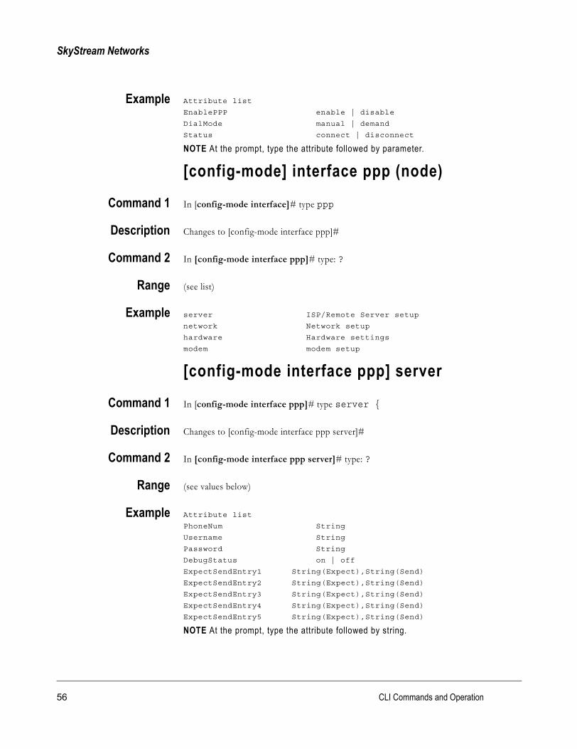
SkyStream Networks
Example Attribute list
EnablePPP enable | disable
DialMode manual | demand
Status connect | disconnect
NOTE At the prompt, type the attribute followed by parameter.
[config-mode] interface ppp (node)
Command 1 In [config-mode interface]# type ppp
Description Changes to [config-mode interface ppp]#
Command 2 In [config-mode interface ppp]# type: ?
Range (see list)
Example server ISP/Remote Server setup
network Network setup
hardware Hardware settings
modem modem setup
[config-mode interface ppp] server
Command 1 In [config-mode interface ppp]# type server {
Description Changes to [config-mode interface ppp server]#
Command 2 In [config-mode interface ppp server]# type: ?
Range (see values below)
Example Attribute list
PhoneNum String
Username String
Password String
DebugStatus on | off
ExpectSendEntry1 String(Expect),String(Send)
ExpectSendEntry2 String(Expect),String(Send)
ExpectSendEntry3 String(Expect),String(Send)
ExpectSendEntry4 String(Expect),String(Send)
ExpectSendEntry5 String(Expect),String(Send)
NOTE At the prompt, type the attribute followed by string.
56 CLI Commands and Operation

EMR-5000 User’s Guide version 2.3
Values
� PhoneNum: Type phone number to access ppp server without spaces including‘9’ for an outside line and ‘1’ for long distance, when required.
� Username: Type user name to access ppp server.
� Password: Type password to access ppp server.
� ExpectSendEntry1: Type String(ogin:),String(your-login)
� ExpectSendEntry2: Type String(word:),String(your-password)
� ExpectSendEntry3: Type String(>),String(ppp)
� ExpectSendEntry4: (etc...)
[config-mode interface ppp] network
Command 1 In [config-mode interface ppp]# type network {
Description Changes to [config-mode interface ppp network]#
Command 2 In [config-mode interface ppp network]# type: ?
Range (see values below)
Example Attribute list
UsePeerDefaultRoute yes | no
MaxRecvUnit Integer
MaxTransUnit IntegerConnectTimeout Integer
NOTE At the prompt, type the attribute followed by string or parameter.
Values
� UsePeerDefaultRoute: Type “yes” or “no.”
� MaxRecvUnit: Type (default 1500 bytes)
� MaxTransUnit: Type (default 1500 bytes)
� ConnectTimeout: Type number of seconds for connecting (120 default)
57

SkyStream Networks
[config-mode interface ppp] hardware
Command 1 In [config-mode interface ppp]# type hardware {
Description Changes to [config-mode interface ppp hardware]#
Command 2 In [config-mode interface ppp hardware]# type: ?
Range (see values below)
Example Attribute list
LineSpeed 1200|2400|4800|9600|19200|57600
HwFlowControl enable | disable
NOTE At the prompt, type the attribute followed by string.
Values
� LineSpeed: Type (baud rate of modem—1200, 2400, 4800, 9600, 19200, 57600)
� HwFlowControl: Type “Enable” or “Disable”
[config-mode interface ppp] modem
Command 1 In [config-mode interface ppp]# type modem {
Description Changes to [config-mode interface ppp modem]#
Command 2 In [config-mode interface ppp modem]# type: ?
Range (see values below)
Example Attribute list
InitString String
DialString String
NOTE At the prompt, type the attribute followed by string.
Values
� InitString: Type ATZ ATE1VE1V1Q0 (default)
� DialString: Type ATDT (default) 8 characters
58 CLI Commands and Operation

EMR-5000 User’s Guide version 2.3
[config-mode] interface isdn (optional)
Command 1 In [config-mode interface]# type: isdn {
Description Changes to [config-mode interface isdn]#
Command 2 In [config-mode interface isdn]# type: ?
Description The configuration option list appears, which shows all the configurable optionsavailable for ISDN.
Range (see list)
Example Attribute list
Status manual-dial | demand-dial | disconnect
NOTE At the prompt, type the attribute followed by string.
[config-mode] interface isdn (optional)
Command 1 In [config-mode interface]# type: isdn
Description Changes to [config-mode interface isdn]#
Command 2 In [config-mode interface isdn]# type: ?
Range (see list)
Example server SP/Remote ISDN Server Setup
ppp ISDN-PPP Setup
line ISDN Line Settings
[config-mode interface isdn] server
Command 1 In [config-mode interface isdn]# type: server {
Description Changes to [config-mode interface isdn server]#
Command 2 In [config-mode interface isdn server]# type: ?
Range (see values below)
59

SkyStream Networks
Example Attribute list
PhoneNumber String
UserName String
Password String
NOTE At the prompt, type the attribute followed by string.
Values
� PhoneNum: Type phone number to access isdn server without spaces including‘9’ for an outside line and ‘1’ for long distance, when required.
� Username: Type user name to access isdn server.
� Password: Type password to access isdn server.
[config-mode interface isdn] ppp
Command 1 In [config-mode interface isdn]# type: ppp {
Description Changes to [config-mode interface isdn ppp]#
Command 2 In [config-mode interface isdn ppp]# type: ?
Range (see values below)
Example Attribute list
UseThisAsDefaultRoute yes | no
VJHeaderCompression enable | disable
BChannel String
MRU Integer
MTU Integer
IPAddressNegotiation enable | disable
RequestedIPAddress String
RequestedRemoteIPAddress String
NOTE At the prompt, type the attribute followed by string.
Values
� UseThisAsDefaultRoute: Type “yes” or “no”
� VJHeaderCompression: Type “enable” or “disable”
� BChannel: Type “onechannel” or twochannels”
� MRU: Type 2000 (default maximum receive unit in bytes)
� MTU: Type 1500 (default maximum transmit unit bytes)
� IPAdvancedNegotiation: Type “enable” or “disable”
� RequestedIPAddress: Type (xxx.xxx.xxx.xxx) EMR IP address (0.0.0.0 willnegotiate actual IP address during connection)
60 CLI Commands and Operation

EMR-5000 User’s Guide version 2.3
� RequestedRemoteIPAddress: Type (xxx.xxx.xxx.xxx) remote ISP IP address(optional)
[config-mode interface isdn] line
Command 1 In [config-mode interface isdn]# type: line {
Description Changes to [config-mode interface isdn line]#
Command 2 In [config-mode interface isdn line]# type: ?
Range (see values below)
Example Attribute list
DChannelProtocol String
MSNEAZ1 String
MSNEAZ2 String
SPID1 String
SPID2 String
NOTE At the prompt, type the attribute followed by string.
Values
� DChannelProtocol: Type one of the following values: Protocol 1TR6,Protocol EDSS1, Protocol Leased, or Protocol NI1.
� MSNEAZ1: Type Multiple Subscriber Number or Endgeraete Auswahl Ziffer(Germany) Obtain these numbers from your Internet Service Provider.
� MSNEAZ2: (same as above)
� SPID1: Type Service Profile Identifier is an additional identifier used to identifythe EMR ISDN device to the telephone network. Obtain these numbers fromyou Internet Service Provider.
� SPID2: (same as above)
NOTE SPID is available by selecting Protocol NI1 as the D-Channel Protocol.
[config-mode] interface sync (optional)
Command 1 In [config-mode interface]# type: sync {
Description Changes to [config-mode interface sync]#
Command 2 In [config-mode interface sync]# type: ?
61

SkyStream Networks
Description The configuration option list appears, which shows all the configurable optionsavailable for Sync.
Range (see values below)
Example Attribute list
PID PidValueSerialBitShift MSB/LSBSpeed Integer
NOTE At the prompt, type the attribute followed by parameter.
Values
� PID: Type PID <Value> (i.e. 95 in dec. or 5F in Hex.)
� SerialBitShift: Type “MSB” or “LSB.” See SMR User’s Guide, Chapter 5,“Configure Sync In Hardware Driver.”
� Speed: Type <integer> (range is 1 to 8 Mbits/s)
[config-mode] active_macs1
Command 1 In [config-mode]# type: active_macs1 {
Description Changes to [config-mode active_macs1]#
Command 2 In [config-mode active_macs]# type: ?
Description Configure active MAC Addresses
Range (All MAC addresses entered by user)
Example Attribute listActive MACAddr String
NOTE Type the MAC address at the prompt in the following format:00:00:00:00:00:00
Command 3 Type: 00:30:1d:00:04:c2
62 CLI Commands and Operation

EMR-5000 User’s Guide version 2.3
[config-mode] active_pids1
Command 1 In [config-mode]# type: active_pids1 {
Description Changes to [config-mode active_pids1]#
Command 2 In [config-mode active_pids]# type: ?
Description Add active PIDs
Range 0-8191
Example Attribute listPID PidValue
NOTE At the prompt, type a PID number. Check to see if system is in decimalor hexadecimal configuration mode.
Command 3 Type: 32
[config-mode] active_fkcas1
Command 1 In [config-mode]# type: active_fkcas1 {
Description Changes to [config-mode active_fkcas1]#
Command 2 In [config-mode active_fkcas1]# type: ?
Description Add active PID, fixed key, and parity
Range (Fixed keys added by user)
Example Attribute listPID PidValue
Key xx-xx-xx-xx-xx-xx-xx-xx
Parity odd/even
NOTE At the prompt, type the string of parameters separated with a space.
[config-mode] skycast
Command 1 In [config-mode]# type: skycast {
63

SkyStream Networks
Description Changes to [config-mode skycast]#
Command 2 In [config-mode skycast]# type: ?
Description Configure SkyCast
Range (see values below)
Example Attribute list
Status enable | disable
DefaultOrgDestIPAddr IP Address (A.B.C.D)
DefaultNetmask IP Address (A.B.C.D)
DefaultTTL Integer
DefaultAction fwd | fwd-if-listner | discard
DefaultFwdOutNetworkIf eth1 | eth2
NOTE At the prompt, type attribute followed by parameter.
Values
� Status: Type “enable” or “disable” to turn SkyCast on or off
� DefaultAction: Type “fwd”, “fwd-if-listner” or “discard” for default
- Forward : Sends the Mult icast packets into the local networkunconditionally.
- Forward If Listener: Sends the Multicast packets from this multicastgroup into the network if there is a group member present
- Discard: Discards all packets belonging to this group.
� DefaultNewDestIPAddr: Type the new destination IP address for default
� DefaultTTL: Type an integer. If you leave this value as zero, the TTL willremain unchanged
[config-mode] skycast_rule
Command 1 In [config-mode]# type: skycast_rule {
Description Changes to [config-mode skycast_rule]#
Command 2 In [config-mode skycast_rule]# type: ?
Description Configure skycast rules
Range (see values below)
64 CLI Commands and Operation

EMR-5000 User’s Guide version 2.3
Example Attribute listOrgDestIPAddr IP Address (A.B.C.D)NewDestIPAddr IP Address (A.B.C.D)TTL IntegerAction fwd | fwd-if-listener | discardOutNetworkIf eth1 | eth2 Netmask IP Address (A.B.C.D)
NOTE At the prompt, type the string of parameters separated with a space.
Values
� OrgDestIPAddr: Type IP address for original destination of the data stream
� NewDestIPAddr: Type the IP address for the new destination of the datastream
� TTL: Type an integer. If you leave this value as zero, the TTL will remainunchanged
� Action: Type one of the forwarding options:
- Forward : Sends the Mult icast packets into the local networkunconditionally.
- Forward If Listener: Sends the Multicast packets from this multicastgroup into the network if there is a group member present.
- Discard: Discards all packets belonging to this group.
� OutNetworkIf: Type “eth1” or “eth2” to select the out interface
� NetMask: Type the related Net Mask information
Command 3 In [config-mode skycast_rule]# type:192.168.100.0 224.6.6.6 4 fwd-if-listner eth1 255.255.255.255
[config-mode] skynat1
Command 1 In [config-mode]# type: skynat1 {
Description Changes to [config-mode skynat1]#
Command 2 In [config-mode skynat1]# type: ?
Description Enables SkyNAT
Range (see list below)
65

SkyStream Networks
Example Attribute listnat_status enable | disablenpt_status enable | disable
Command 3 Type: nat_status enable
[config-mode skynat1]NOTE The suffix number ‘1’ refers to the number of the receiver card.
Command 1 In [config-mode]# type: skynat1
NOTE This command is similar to the one before except it does not use a “{“.
Description Changes to [config-mode skynat1]#
Command 2 In [config-mode skynat1]# type: ?
Description Configure SkyNAT’s two options: Address translation rule list, and Protocoltranslation rule list
Range (see list below)
Example skynat_rules Network address translation rule listskynpt_rules Network protocol translation rule list
[config-mode skynat1 skynat_rules]
Command 1 In [config-mode skynat1]# type: skynat_rules {
Description Changes to [config-mode skynat1 skynat_rules]#
Command 2 In [config-mode skynat1 skynat_rules]# type: ?
Description Configure address translation rule list
Range (see values below)
Example Attribute listOrgDestIPAddr IP Address (A.B.C.D)NewDestIPAddr IP Address (A.B.C.D)TTL IntegerNetmask IP Address (A.B.C.D)
NOTE At the prompt, type the string of parameters separated with a space.
66 CLI Commands and Operation

EMR-5000 User’s Guide version 2.3
Values� OrgDestIPAddr: Type IP address for original destination of the data stream
� NewDestIPAddr: Type the IP address for the new destination of the datastream
� TTL: Type an integer. If you leave this value as zero, the TTL will remainunchanged
� NetMask: Type the related Net Mask information
[config-mode skynat1 skynpt_rules]
Command 1 In [config-mode skynat1]# type: skynpt_rules {
Description Changes to [config-mode skynat1 skynpt_rules]#
Command 2 In [config-mode skynat1 skynpt_rules]# type: ?
Description Configure address translation rule list
Range (see values below)
Example Attribute listOrgDestIPAddr IP Address (A.B.C.D)UDPPort Integer (1..65535)
TCPPort Integer (1 .. 65535)
NOTE At the prompt, type the string of parameters separated with a space.Values
� OrgDestIPAddr: Type IP address for original destination of the data stream
� UDPPort: Type an integer (customer specific)
� TCPPort: Type an integer (customer specific)
[config-mode] snmp
Command 1 In [config-mode]# type: snmp
Description Changes to [config-mode snmp]#
Command 2 In [config-mode snmp]# type: ?
Description Configure SNMP information
67

SkyStream Networks
Range (see list)
Example mib2sys Mib-2 System settingsaccess Snmp access listtrap trap list
[config-mode snmp mib2sys]
Command 1 In [config-mode snmp]# type: mib2sys {
Description Changes to [config-mode snmp mib2sys]#
Range (see values below)
Command 2 In [config-mode snmp mib2sys]# type: ?Attribute listSysContact StringSysLocation String
NOTE At the prompt, type the string of parameters separated with a space.
Values� SysContact:� SysLocation:
[config-mode snmp access]
Command 1 In [config-mode snmp]# type: access {
Description Changes to [config-mode snmp access]#
Range (see values below)
Command 2 In [config-mode snmp access]# type: ?Attribute list
Community String
Access ro | rw
NOTE At the prompt, type the string of parameters separated with a space.
Values� Community: Type “Public” which ensures that only people on the local
network can get information on the SNMP.
� Access Control: Type “ro” Read_Only or “rw” Read_Write access.
68 CLI Commands and Operation

EMR-5000 User’s Guide version 2.3
[config-mode snmp trap]
Command 1 In [config-mode snmp]# type: trap {
Description Changes to [config-mode snmp trap]#
Range (see values below)
Command 2 In [config-mode snmp trap]# type: ?Attribute ListTrapDest IP Address (A.B.C.D)Community String
NOTE At the prompt, type the string of parameters separated with a space.
Values� Trap Destination: Type IP Address for trap destination.
� Community: Type “Public” which ensures that only people on the localnetwork can get information on the SNMP.
[config-mode] tcpX
Command 1 In [config-mode]# type: tcpX
Description Changes to [config-mode tcpX]#
Command 2 In [config-mode tcpX]# type: ?
Description Configure TCP Acceleration
Range (see list)
Example network Network settings
compression Compression settings
userport User Defined Ports settings
69

SkyStream Networks
[config-mode tcpX] network
Command 1 In [config-mode tcpX]# type: network
Description Changes to [config-mode tcpX network]#
Command 2 In [config-mode tcpX network]# type: ?
Description Configure TCP Acceleration Network Settings
Range (see list)
Example server Server settingsclient Client settings
[config-mode tcpX network] server
Command 1 In [config-mode tcpX network]# type: server {
Description Changes to [config-mode tcpX network server]#
Command 2 In [config-mode tcpX network server]# type: ?
Description Configure TCP Acceleration Network Settings for server side
Range (see values below)
Example Attribute list
PrimaryRemoteServerAddr IP Address (A.B.C.D)
PrimaryRemoteServerPort Integer
SecondaryRemoteServerAddr IP Address (A.B.C.D)
SecondaryRemoteServerPort Integer
POP3ServerAddr IP Address (A.B.C.D)
POP3ServerPort Integer
SMTPServerAddr IP Address (A.B.C.D)
SMTPServerPort Integer
NNTPServerAddr IP Address (A.B.C.D)
NNTPServerPort Integer
NOTE At the prompt, type attribute followed by parameter.
70 CLI Commands and Operation

EMR-5000 User’s Guide version 2.3
Values� PrimaryRemoteServerAddr: Type IP address for TCP Acceleration primary
server
� PrimaryRemoteServerPort: Type port number for TCP Acceleration primaryserver
� SecondaryRemoteServerAddr: Type IP address for TCP Accelerationsecondary server
� SecondaryRemoteServerPort: Type port number for TCP Accelerationsecondary server
� POP3ServerAddr: Type IP address for e-mail server to send mail.
� POP3ServerPort: Type port number for e-mail server to send mail.
� SMTPServerAddr: Type IP address for e-mail server to receive mail.
� SMTPServerPort: Type port number for e-mail server to receive mail.
� NNTPServerAddr: Type IP address of Network News server.
� NNTPServerPort: Type port number of Network New server.
NOTE After entering a new attribute, you can check it by typing the showrunning-config command.
[config-mode tcpX network] client
Command 1 In [config-mode tcpX network]# type: client {
Description Changes to [config-mode tcpX network client]#
Command 2 In [config-mode tcpX network client]# type: ?
Description Configure TCP Acceleration Network Settings for client side
Range (see values below)
Example Attribute list
HTTPListenPort Integer
POP3ListenPort Integer
FTPListenPort Integer
SSLListenPort Integer
SMTPListenPort Integer
NNTPListenPort Integer
NOTE At the prompt, type attribute followed by parameter.
71

SkyStream Networks
Values� HTTPListenPort: Type HTTP port used by the TCP Acceleration client
(default is 9090).
� POP3ListenPort: Type POP3 port used by the TCP Acceleration client
� FTPListenPort: Type FTP port used by the TCP Acceleration client (default is9091).
� SSLListenPort: Type SSL port used by the TCP Acceleration client (default is9092).
� SMTPListenPort: Type SMTP port used by the TCP Acceleration client.
� NNTPListenPort: Type NNTP port used by the TCP Acceleration client.
[config-mode tcpX] compression
Command 1 In [config-mode tcpX]# type: compression {
Description Changes to [config-mode tcpX compression]#
Command 2 In [config-mode tcpX compression]# type: ?
Description Configure TCP Acceleration Compression Settings
Range (see list)
Example Attribute list
CompressionStatus enabled | disabled
CompressionLevel 1..9
HTTPCompressionStatus yes | no
FTPCompressionStatus yes | no
NOTE At the prompt, type file extensions required.
Command 3 Type: xls
To delete extensions
Type: no xls
[config-mode tcpX] userport
Command 1 In [config-mode tcpX]# type: userport {
Description Changes to [config-mode tcpX userport]#
72 CLI Commands and Operation

EMR-5000 User’s Guide version 2.3
Command 2 In [config-mode tcpX userport]# type: ?
Description Configure TCP Acceleration User Defined Ports settings
Range (see values below)
Example Attribute listFreeTcpServerAddr IP Address (A.B.C.D)
ServerPort Integer
ClientPort Integer
NOTE At the prompt, type the string of parameters separated with a space.
Values� FreeTcpServerAddr: Type IP address used by TCP Acceleration primary
server.
� ServerPort: Type server side port number.
� ClientPort: Type client side port number (default is 5631).
[config-mode] turbointernet-vpn
Command 1 In [config-mode]# type: turbointernet-vpn
Description Changes to [config-mode turbointernet-vpn]#
Command 2 In [config-mode turbointernet-vpn]# type: ?
Description ConfigureTurbo Internet-VPN
Range (see list)
Example pptp PPTP Configuration
ipsec IPSec settings
connection Connection Method
advanced Advanced settings
[config-mode turbointernet-vpn] pptp
Command 1 In [config-mode turbointernet-vpn]# type: pptp {
Description Changes to [config-mode turbointernet-vpn pptp]#
Command 2 In [config-mode turbointernet-vpn pptp]# type: ?
73

SkyStream Networks
Description ConfigureTurbo Internet-VPN PPTP
Range (see values below)
Example Attribute list
ServerIPAddress String
Username String
Password String
SatelliteMacFilter tunneladdress | pppaddress
NOTE At the prompt, type attribute followed by string.
Values� ServerIPAddress: Type IP address of of the Windows PPTP server or VPN
concentrator.
� Username: Type your Windows server domain name followed by ‘\\’ andWindows username, for example: domain\\username.
� Password: Type a password.
� SatelliteMacFilter: Type “tunneladdress” or “pppaddress.”
[config-mode turbointernet-vpn] ipsec
Command 1 In [config-mode turbointernet-vpn]# type: ipsec {
Description Changes to [config-mode turbointernet-vpn ipsec]#
Command 2 In [config-mode turbointernet-vpn ipsec]# type: ?
Description ConfigureTurbo Internet-VPN IPSec
Range (see list)
Example Attribute list
IPSecConf IPSec configuration
IPSecKeyExchange IPSec Internet Key Exchange
IPSecSecurity IPSec Security Associations
74 CLI Commands and Operation

EMR-5000 User’s Guide version 2.3
[config-mode turbointernet-vpn ipsec] IPSecConf
Command 1 In [config-mode turbointernet-vpn ipsec]# type: IPSecConf {
Description Changes to [config-mode turbointernet-vpn ipsec IPSecConf]#
Command 2 In [config-mode turbointernet-vpn ipsec IPSecConf]# type: ?
Description ConfigureTurbo Internet-VPN IPSec
Range (see values below)
Example Attribute list
GatewayIPAddress String
IPSecMode String
RemoteSubnet String
RemoteSubnetMask String
LocalSubnet String
LocalSubnetMask String
NOTE At the prompt, type attribute followed by string.
Values� GatewayIPAddress: Type IP address of remote gateway.
� IPSecMode: Type string
� RemoteSubnet: Type remote subnet address (leave blank if not used).
� RemoteSubnetMask: Type remote subnet mask address (leave blank if notused).
� LocalSubnet: Type local subnet address (leave blank if not used).
� LocalSubnetMask: Type local subnet mask address (leave blank if not used).
[config-mode turbointernet-vpn ipsec] IPSecKeyExchange
Command 1 In [config-mode turbointernet-vpn ipsec]# type: IPSecKeyExchange {
Description Changes to [config-mode turbointernet-vpn ipsec IPSecKeyExchange]#
Command 2 In [config-mode turbointernet-vpn ipsec IPSecKeyExchange]# type: ?
75

SkyStream Networks
Description ConfigureTurbo Internet-VPN IPSec Key Exchange
Range (see values below)
Example Attribute list
EncryptionAlgorithm String
AuthAlgorithm String
DiffHellman String
AuthMode String
SharedSecret String
NOTE At the prompt, type attribute followed by string.
Values� EncryptionAlgorithm: Type string
� AuthAlgorithm: Type string
� DiffHellman: Type string
� AuthMode: Type pre-shared key.
� SharedSecret: Type prearranged phrase to use as a key.
[config-mode turbointernet-vpn ipsec] IPSecSecurity
Command 1 In [config-mode turbointernet-vpn ipsec]# type: IPSecSecurity {
Description Changes to [config-mode turbointernet-vpn ipsec IPSecSecurity]#
Command 2 In [config-mode turbointernet-vpn ipsec IPSecSecurity]# type: ?
Description ConfigureTurbo Internet-VPN IPSec Security
Range (see values below)
Example Attribute list
UseAuthHeader String
AHAuthenticationAlgorithm String
UseESP String
ESPEncryptionAlgorithm String
ESPAuthenticationAlgorithm String
ReplaceKeyEverySeconds Integer
ReplaceKeyEveryKBs Integer
NOTE At the prompt, type attribute followed by string or parameter.
76 CLI Commands and Operation

EMR-5000 User’s Guide version 2.3
Values� UseAuthHeader: Type string
� AHAuthenticationAlgorithm: Type string
� UseESP: Type string
� ESPEncryptionAlgorithm: Type string
� ESPAuthenticationAlgorithm: Type string
� ReplaceKeyEverySeconds: Type string
� ReplaceKeyEveryKBs: Typestring
[config-mode turbointernet-vpn] connection
Command 1 In [config-mode turbointernet-vpn]# type: connection {
Description Changes to [config-mode turbointernet-vpn connection]#
Command 2 In [config-mode turbointernet-vpn connection]# type: ?
Description ConfigureTurbo Internet-VPN Connection
Range (see values below)
Example Attribute list
ConnectionUsing String
InitialConnection String
NOTE At the prompt, type attribute followed by string.
Values� ConnectionUsing: Type
� InitialConnection: Type
[config-mode turbointernet-vpn] advanced
Command 1 In [config-mode turbointernet-vpn]# type: advanced {
Description Changes to [config-mode turbointernet-vpn advanced]#
77

SkyStream Networks
Command 2 In [config-mode turbointernet-vpn advanced]# type: ?
Description ConfigureTurbo Internet-VPN Advanced
Range (see values below)
Example Attribute list
NATApplied none|ethernet-1|ethernet-2|all
MacPrefix String
NOTE At the prompt, type attribute followed by string.
Values� NATApplied: Type “none,” “ethernet-1,” “ethernet-2,” or “all.”
� MACPrefix: Type hexadecimal (default is “0000”).
maintenance
Command Type: maintenance ?
Description Shows all maintenance subcommands
Range (All maintenance subcommands)
Example kernel_list List of currently installed kernelsboot_mode get/set kernel boot modesw_upgrade Upgrade new software through ftpkey_upgrade Get or set upgrade keyreset_counter reset satrx interface countersconfiguration configuration file operationstcpXmode disable/enable Tcp Acceleration mode
maintenance kernel_list
Command Type: maintenance kernel_list
Description Displays kernel list for maintenance purposes
Range (see list below)
Example Installed kernel list:EMR.00.09(default)EMR-2.4.0-5000
78 CLI Commands and Operation

EMR-5000 User’s Guide version 2.3
maintenance boot_mode
Command 1 Type: maintenance boot_mode
Description Selects the boot mode.
Example Usage : maintenance bootmode [get | [set <auto> | [<manual> <id>]] ]
NOTE If maintenance boot_mode is set to “auto” the boot loader will load thekernel that is most up-to-date. If set to “manual,” the user must set a kernelthat is available. This will be loaded the next boot-time.
Command 2 Type: maintenance boot_mode get
Description Gets settings
Range (see list)
Example Current Boot mode is AUTO
Command 3 Type: maintenance boot_mode set manual EMR-2.4.0-5000
NOTE Check maintenance kernel_list to see what kernels are available.
Description Sets bootmode
Range (see list)
Example Success!! kernel EMR-2.4.0-5000 will boot next time
maintenance sw_upgrade
Command 1 Type: maintenance sw_upgrade
Description Downloads and installs a new software load.
Range (see list)
Example sw_upgrade
Usage : maintenance sw_upgrade ftp <action> [IPAddr] [ -u user [ -p password ] ] [-r rootpath] {file}
options :
79

SkyStream Networks
action : get, list
IPAddr : specifies the IP Address of the remote system
-u user : specifies the username to log in with on host
-p password : specifies the password to log in with on host
-r rootpath : change remote working directory
If user is not specified, then the default will be 'anonymous'
Command 2 Type: maintenance sw_upgrade ftp get www.skystream.com-u my_name -p my_pwd -r/kernel/skyemr/ EMR_2.4.0-5000
maintenance key_upgrade
Command 1 Type: maintenance key_upgrade
Description Installs an upgrade key to enable advanced capabilities.
Range (see list)
Example Usage : maintenance key_upgrade [get | set <upgrade key>]
NOTE When upgrading your EMR to enhance its capabilities, you will receivean Upgrade Key string. Upgrade Key 1 provides support for up to 25Msymbols and 32 PIDs per receiver. Upgrade Key 2 provides support for up to45 Msymbols and 64 PIDs per receiver.
Command 2 Type: maintenance key_upgrade get
Description Gets key
Range (see list)
Example upgrade key : HD39D-MDX4-YASWU
Command 3 Type: maintenance key_upgrade set HD39D-MDX4-YASWU
NOTE Check what maintenance upgrade keys are available.
Description Sets upgrade key
80 CLI Commands and Operation

EMR-5000 User’s Guide version 2.3
maintenance reset_counter
Command Type: maintenance reset_counter ?
Description Resets interface counters
Range (see list)
Example satrx1 reset Satrx1 counters
maintenance configuration
Command Type: maintenance configuration ?
Description Displays subcommands for saving, deleting, loading and sett ing defaultconfiguration files
Range (see list below)
Example list List all configuration files
wrt Save configuration file
del Delete configuration file
load Load configuration file
default Set default configuration file
factory Restore factory default configuration
maintenance configuration list
Command Type: maintenance configuration list
Description Displays a list of configuration files
Range (see list)
Example current configuration files
filename : config1
desc : 1240, 20, 2 PIDs
default : yes
81

SkyStream Networks
maintenance configuration wrt
Command Type: maintenance configuration wrt
Description Writes the configuration file.
Range (see list)
Example Usage : maintenance configuration wrt -d [ <filename> <desc> ]options :
-d : save the session as default
NOTE By typing a configuration filename and description after the command,and pressing Enter, the EMR will write to flash memory and permanently savethe file.
maintenance configuration del
Command Type: maintenance configuration del
Description Deletes a configuration file.
Range (see list)
Example Usage : maintenance configuration del [<filename>]
NOTE By typing the name of the file after the command, and pressing Enter,the EMR will delete the configuration file from memory.
maintenance configuration load
Command Type: maintenance configuration load
Description Loads a configuration file.
Range (see list)
Example Usage: maintenance configuration load [<filename>]
NOTE By typing the name of the file after the command, and pressing Enter,the EMR will load the configuration file.
82 CLI Commands and Operation
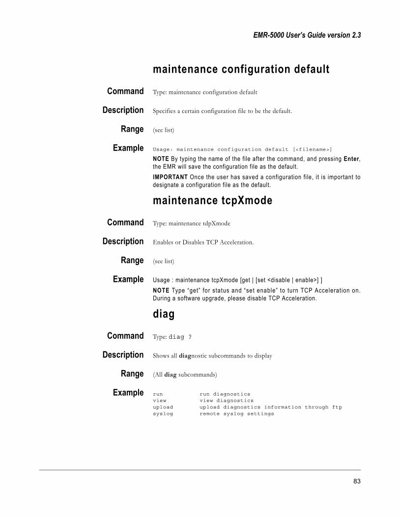
EMR-5000 User’s Guide version 2.3
maintenance configuration default
Command Type: maintenance configuration default
Description Specifies a certain configuration file to be the default.
Range (see list)
Example Usage: maintenance configuration default [<filename>]
NOTE By typing the name of the file after the command, and pressing Enter,the EMR will save the configuration file as the default. IMPORTANT Once the user has saved a configuration file, it is important todesignate a configuration file as the default.
maintenance tcpXmode
Command Type: maintenance tdpXmode
Description Enables or Disables TCP Acceleration.
Range (see list)
Example Usage : maintenance tcpXmode [get | [set <disable | enable>] ]NOTE Type “get” for status and “set enable” to turn TCP Accelerat ion on.During a software upgrade, please disable TCP Acceleration.
diag
Command Type: diag ?
Description Shows all diagnostic subcommands to display
Range (All diag subcommands)
Example run run diagnosticsview view diagnosticsupload upload diagnostics information through ftp syslog remote syslog settings
83

SkyStream Networks
diag run
Command Type: diag run
Description Runs diagnostic and creates a CLI diagnostic file
Range (see list)
Example Writing /tmp/clidiag.txt into diagnostic log.Success!
diag view
Command Type: diag view
Description Displays diagnostic log file
Range (see list)
Example Diagnostics:
50001706
root=/dev/ram rw ramdisk=32000 wdt=0
CPU0
1: 3595 4xx UIC Edge
2: 10378 4xx UIC Edge PPC405 IIC
9: 0 4xx UIC Edge 405eth Wakeup
10: 0 4xx UIC Edge 405eth MAL SERR
11: 21224 4xx UIC Edge 405eth TX EOB
12: 10046299 4xx UIC Edge 405eth RX EOB
13: 0 4xx UIC Edge 405eth TX DE
14: 0 4xx UIC Edge 405eth RX DE
15: 0 4xx UIC Edge 405eth MAC
25: 676 4xx UIC Edge satrx1
28: 2975305 4xx UIC Edge eth2
FIT: 0
BAD: 0
total: used: free: shared: buffers: cached:
Mem: 63582208 56557568 7024640 39485440 27193344 10973184
Swap: 0 0 0
MemTotal: 62092 kB
MemFree: 6860 kB
MemShared: 38560 kB
Buffers: 26556 kB
84 CLI Commands and Operation

EMR-5000 User’s Guide version 2.3
Cached: 10716 kB
Active: 37272 kB
Inact_dirty: 0 kB
Inact_clean: 0 kB
Inact_target: 16 kB
HighTotal: 0 kB
HighFree: 0 kB
LowTotal: 62092 kB
LowFree: 6860 kB
SwapTotal: 0 kB
SwapFree: 0 kB
IP address HW type Flags HW address Mask Device
192.168.4.254 0x1 0x2 00:E0:2B:85:C1:00 * eth1
192.168.4.186 0x1 0x2 00:03:47:70:7A:BF * eth1
Ip: Forwarding DefaultTTL InReceives InHdrErrors InAddrErrors ForwDatagrams InUn--More--(
knownProtos InDiscards InDelivers OutRequests OutDiscards OutNoRoutes ReasmTimeo--More--( (note: this is a fragment of the log file).
diag upload
Command 1 Type: diag upload
Description Uploads the diagnostic results.
Range (see example)
Example Usage : diag upload ftp <action> [IPAddr] [ -D | -L ] [ -u user [ -p password ]] [-r rootpath] {file}options :
action : putIPAddr : specifies the IP Address of the remote system-D : upload Diagnostic file-L : upload skyLog file-u user : specifies the username to log in with on host-p password : specifies the password to log in with on host-r rootpath : change remote working directory
If user is not specified, then the default will be 'anonymous'
Command 2 Type: diag upload ftp put 192.168.4.100 -D -u my_name -p my_pwd -r/kernel/skyemr/diag.txt
85

SkyStream Networks
diag syslog
Command Type: diag syslog
Description Shows syslog usage
Range (see example)
Example Usage : diag syslog [-l] | [enable | disable <ipaddr> ]options :-l : list remote syslog entry
Command 2 Type: diag syslog -l
Description Lists remote syslog entry
stats
Command Type: stats ?
Description Shows all statistics subcommands to display
Range (All stats subcommands)
Example satrx1 Display SatRx1 statisticseth1 Display eth1 statisticseth2 Display eth2 statisticstcpX Display tcpX statisticsppp Display ppp statistics
isdn Display isdn statistics
turbointernet-vpn Display turbointernet-vpn statisticssync Display sync statistics
stats satrx1
Command Type: stats satrx1
Description Shows all statistics for satrx1
Range (All satrx1 statistics)
Example Satrx1current statistics
86 CLI Commands and Operation

EMR-5000 User’s Guide version 2.3
M2T Packets Received :54740048M2T Packets Dropped :189Bad Continuity Count Pkts :189IP Packets Generated :14079529IP Packets Dropped :18IP Packets Sent :13321546IP Packets Discarded :0IP Multicast Packets :2754IP Unicast Packets :13321546
stats eth1Command Type: stats eth1
Description Shows all statistics for eth1
Range (All eth1 statistics)
Example Eth1current statistics
Bytes received :19508263Packets received :78966Bytes sent :13002796Packets sent :115654InPacket Errors :0OutPacket Errors :0Collisions :0
stats eth2Command Type: stats eth2
Description Shows all statistics for eth2
Range (All eth2 statistics)
Example Eth2current statistics
Bytes received :1713183662Packets received :10979301Bytes sent :3138600Packets sent :44346InPacket Errors :0OutPacket Errors :0collisions :0
stats tcpX (optional)Command Type: stats tcpX
87

SkyStream Networks
Description Shows all statistics for tcpX
Range (All tcpX statistics)
Example tcpXcurrent statistics
Current connections :2
stats pppCommand Type: stats ppp
Description Shows all statistics for PPP
Range (All ppp statistics)
Example PPP Statistics
current statistics
Bytes Received :8173
Bytes Sent :5676
Packets Sent :92
InPacket Errors :0
OutPacket Errors :0
Collisions :0
stats isdn (optional)Command Type: stats isdn
Description Shows all statistics for ISDN
Range (All isdn statistics)
Example ISDN Statistics
current statistics
Interface Status :Up
Local IP Address :209.245.132.211
Remote IP Address :209.244.43.89
Subnet Mask :255.255.255.0
L2 Protocol :L2_HDLC
L2 Protocol :L2_HDLC
MRU :2000
MTU :1500
Bytes Sent :40484
Bytes Received :20909
88 CLI Commands and Operation

EMR-5000 User’s Guide version 2.3
Packets Sent :552
Packets Sent :263
InPacket Errors :0
OutPacket Errors :0
stats turbointernet-vpn Command Type: stats turbointernet-vpn
Description Shows all statistics for Turbo Internet/VPN
Range (All turbointernet-vpn statistics)
PPTP Example TurboInternet/VPN Statistics
current PPTP statistics
Status :connected
PPTPServer :64.165.192.147
EncryptionMethod :MPPE
Mode :Stateless encryption
KeyLength :128
ConnectionTime :00:01:01
LocalTunnelIPAddr :64.165.192.144
RemoteTunnelIPAddr :64.165.192.147
SubnetMask :255.255.255.255
Bytes Sent :1677
Bytes Received :4196
Packets Sent :36
Packets Received :16
InPacket Errors :0
OutPacket Errors :0
Collisions :0
current IPSec General statistics
Status :disconnected
stats sync (optional)Command Type: stats sync
Description Shows all statistics for sync
Range (All sync statistics)
Example Sync Statistics current statistics
HDLC Frames Received :0
HDLC Frames Processed :2147483212
HDLC Frames Dropped :2147483040
89

SkyStream Networks
90 CLI Commands and Operation
EMR-5000 User’s Guide version 2.3
Chapter 5: Web GUI Configuration
91

SkyStream Networks
Web GUIIn this chapter you will learn how to navigate and configure the SkyStream EMRusing the Web GUI.
Using SkyStream EMR
On the left side of the EMR home page are five buttons giving the user access tothe following pages: Home, Statist ics, Configuration, Maintenance, andDiagnostics. Additional linked options appear under each of the major topicswhen you click on them.
92 Web GUI Configuration

EMR-5000 User’s Guide version 2.3
HomeThe Home page displays a short animation showing the basic flow of data fromthe satellite through the EMR to the listeners.
StatisticsThe Statistics pages display information about the Satellite Receiver, NetworkInterfaces, SkyCast (IGMP), SkyNAT, DHCP Ser ver, PPP, ISDN, TCPAcceleration, Sync and Turbo Internet/VPN settings.
ConfigurationThe Configuration pages allow you to modify all the major settings: SatelliteReceiver, Network Interface, PID Selection, MAC Address Selection, StaticRoutes, SkyCast (IGMP), SkyNAT, DHCP Server, SNMP, ISDN, PPP, Fixed KeyCAS, TCP Acceleration, Turbo Internet/VPN, Sync, Date/Time and E-mailNotification.
MaintenanceThe Maintenance pages allow you to download and upgrade software for theSkyStream EMR. In addition, you can change the administrator’s password, setpreferences, load a configuration file, and reboot the system.
DiagnosticsThe Diagnos t i c s pages provide current Software Informat ion, HardwareInformation, and Log File Information; and allows you to run a diagnosticssystem check, as well as utilities such as Ping and Netstat.
Navigation Accessing the different functions on the Web GUI is a simple point and click mouse function.The primary menu options are on the left side of the page. When you click themenu options, you access Statistics, Configuration, Maintenance, and Diagnosticfunctions. By clicking these menu options, new menu specific links will displaybelow the main section. The links allow direct access to monitor and configurethe SkyStream EMR.
Help Topics The Web GUI has instant online Help for every available page and function. To access theHelp information, click the Help link in the upper right corner of the page. TheHelp link displays links to the four menu items (Statistics, Configuration,Maintenance, or Diagnostics). For a complete list of Help Topics, click the linkat the bottom of each Help page.
SkyNAT EMR application used to support packet translation of incoming data from satellite for address translation, protocol translation, and TTL translation. SNMP (Simple Network Management Protocol) A standard protocol to manage devices on the network. Manageable devices contain an SNMP Agent responsible for handling the information/control request.SkyCast: The SkyStream system used for IP Multicast Management.
IGMP (Internet Group Management Protocol) A control protocol used to link a “group” of users to the source of a data stream.DHCP (Dynamic Host Configuration Protocol) Software that automatically assigns IP addresses to client stations logging onto a TCP/IP network. It eliminates having to manually assign permanent IP addresses. DHCP software typically runs in servers and is also found in network devices such as ISDN routers and modem routers that allow multiple users access to the Internet.
93
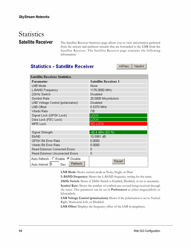
SkyStream Networks
StatisticsSatellite Receiver The Satellite Receiver Statistics page allows you to view information gathered
from the unicast and multicast streams that are forwarded to the EMR from theSate l l i te Rece iver. The Sate l l i t e Receiver page contains the fo l lowinginformation:
LNB Mode: Shows current mode as None, Single, or Dual.L-BAND Frequency: Shows the L-BAND frequency setting for the tuner.22kHz Switch: Shows if 22kHz Switch is Enabled, Disabled, or set to automatic.Symbol Rate: Shows the number of symbols per second being received throughthe tuner. This parameter can be set in Preferences as either megasymbols orkilosymbols.LNB Voltage Control (polarization): Shows if the polarization is set to VerticalRight, Horizontal Left, or Disabled.LNB Offset: Displays the frequency offset of the LNB in megahertz.
94 Web GUI Configuration

EMR-5000 User’s Guide version 2.3
Viterbi Rate: Indicates the Forward Error Correction (FEC) ratio of payload bitsto the total number of bits. For example, if FEC=3/4, then for every 4 bits, 3 bitsare actual data and 1 bit is overhead for error correction.Signal Lock (QPSK Lock): A green bar with the word “LOCK” will appearwhen the frequency and symbol rate are locked. If the signal cannot be locked, thebar will be grayed out.
Data Lock (FEC Lock): A green bar with the word “LOCK” will be displayed ifSymbol Rate, L-Band Frequency, and FEC are set properly. If data cannot belocked, a red bar is displayed with the words “NO LOCK” in the bar.MPE Lock: A green bar with the word “LOCK” will be displayed if data with anMPE header is being received. If data cannot be locked, a red bar is displayed withthe words “NO LOCK” in the bar.Signal Strength: Shows a value and percentage for the signal strength beingreceived from the satellite (-25 dBm to -65 dBm).Eb/N0: Displays the signal to noise ratio value detected by the Satellite Receiverin decibels.QPSK Bit Error Rate: Displays the measured QPSK bit error rate.Viterbi Bit Er ror Rate: Displays the measured er ror rate from the FECalgorithm.Reed Solomon Corrected Errors: Shows the errors that were fixed using theReed Solomon algorithm. These errors indicate that some data was corrupted andthen corrected. Errors are collected over time and will continue to build; a buttonis included on this page to clear the error counters.Reed Solomon Uncorrected Errors: Displays the total number of errors that theReed Solomon Correction Algorithm detected but was unable to correct.
NOTE To reset the error counters to zero click the Reset button.Auto RefreshThe Auto Refresh feature sets how often the system will update the information onthe current page. To configure the Auto Refresh option:1 Click the Enable radio button to activate the Auto Refresh feature.2 In the Auto Interval field, enter the amount of time (in seconds) between
updates for the current page.
3 Click the Refresh button to apply the changes.
MPE (Multi-protocol Encapsulation) A DVB and ATSC packetization format that enables a high-speed gateway to an asymmetric Internet (or private IP-based) network by retransmitting IP information in addition to the payload.
QPSK (Quadrature Phase Shift Keying) A method of modulating digital signals using four phase states to code two digital bits per phase shift.
95

SkyStream Networks
Network Interface The Network Interface Statistics page shows the current network statisticsinformation for the satellite receiver and Ethernet interfaces on the EMR. Thefollowing information displays on the page:
96 Web GUI Configuration

EMR-5000 User’s Guide version 2.3
IP Statistics• MPEG-2 Transport Packets Received: Number of valid MPEG-2 transport
packets received.• MPEG-2 Transport Packets Discarded: Number of MPEG-2 transport
packets discarded due to bad Sync bytes or Null packets.• Error in MPEG-2 Continuity Count: Number of MPEG-2 packets with
continuity count errors.• IP Packets Generated: IP packets that attempted to be reassembled from
MPEG-2 packets with valid PIDs and valid MAC addresses.
• IP Packets Dropped: IP packets generated but dropped because of failed re-assembly.
• IP Packets Discarded: IP packets explicitly discarded because of SkyCastrules if the Action is set to Discard.
• IP Packets Processed: Number of packets sent to IP stack (not directlyforwarded to Ethernet).
• IP Unicast Packets Processed: Unicast Packets sent to IP stack.
• IP Multicast Packets Processed: Multicast Packets sent to IP stack orforwarded.
Auto RefreshSee “Satellite Receiver.”
Satellite Receiver and Ethernet Parameters• Status: Displays if the receiver(s) and Ethernet connections on the EMR are
active by displaying either “UP” or “DOWN.”• Link Status: Shows the status of the physical Ethernet link (10 Mbps, or 100
Mbps; full duplex, half duplex, or none). The EMR auto-regulates dependingon the stream flowing in one direction or both directions at a time.
• IP Address: Shows current IP addresses.
• Subnet Mask: Shows current Subnet Mask settings.
• MAC Address: Shows current MAC Address on the satellite receiver andEthernet connections on the EMR.
• DHCP: Shows if DHCP server is enabled or not.
Packets Any block of data sent over a network. Each packet can contain sender, receiver, and error-control information, in addition to the actual message. Packets can be of fixed-length or variable-length and reassembled, if necessary, when they reach their destination.
97

SkyStream Networks
Ethernet Statistics• Bytes Received: Shows number of bytes received via Eth 1 and/or Eth 2.
• Bytes Sent: Shows number of bytes sent via Eth 1 and/or Eth 2.
• Packets Received: Shows number of packets received via Eth 1 and/or Eth2.
• Packets Sent: Shows number of packets sent through Eth 1 and/or Eth 2.
• InPacket Errors: Shows number of errors in packets coming in.
• OutPacket Errors: Shows number of errors in packets going out.
Ethernet Transmit Events• Total collisions: Shows the total number of single and multiple collisions.
• Single collisions: Shows the total number of single collisions.
• Multiple collisions: Shows the total number of multiple collisions.
• CRC errors: Shows number of frames that received invalid checksum. This isusually caused by interference from nearby radio traffic.
• Loss of carrier: Shows number of times the carrier was lost duringtransmission. This error may indicate a problem with a cable.
• PHY lockup corrected: Debugging statistics for Ethernet 1.
• Packets dropped - waiting for ARP: Shows number of packets droppedwhile waiting for node to respond to an ARP request.
• Packets dropped - excessive collisions: Shows number of times the framefailed to transmit because of excessive collisions. This usually indicates thatthe frame had to be continuously retried due to heavy traffic on Ethernetinfrastructure.
• Packets dropped - excessive deferrals: Shows number of times the framesfailed to transmit because of excessive deferrals. This may indicate a node onthe LAN is using more aggressive back off delay than this one.
• Packets dropped - late collisions: Shows number of times a collisionoccurred after the sixty-fourth byte of a frame was transmitted. This usuallyindicates a cable problem on the Ethernet infrastructure.
Ethernet Receive Events• Flow control packets: Shows number of flow control packets.
• False carrier events: Shows number of false carrier events.
• Invalid data symbols: Shows number of invalid data symbols.
• Alignment (framing) errors: Shows number of frames received whose sizein bits was not a multiple of 8. Occasionally, extra bits of data areinadvertently attached to a transmitted packet causing a frame alignmenterror.
ARP (Address Resolution Protocol) A TCP/IP protocol used to obtain a node's physical address. A client station broadcasts an ARP request onto the network with the IP address of the target node it wishes to communicate with, and the node with that address responds by sending back its physical address so that packets can be transmitted. ARP returns the layer 2 address for a layer 3 address
98 Web GUI Configuration
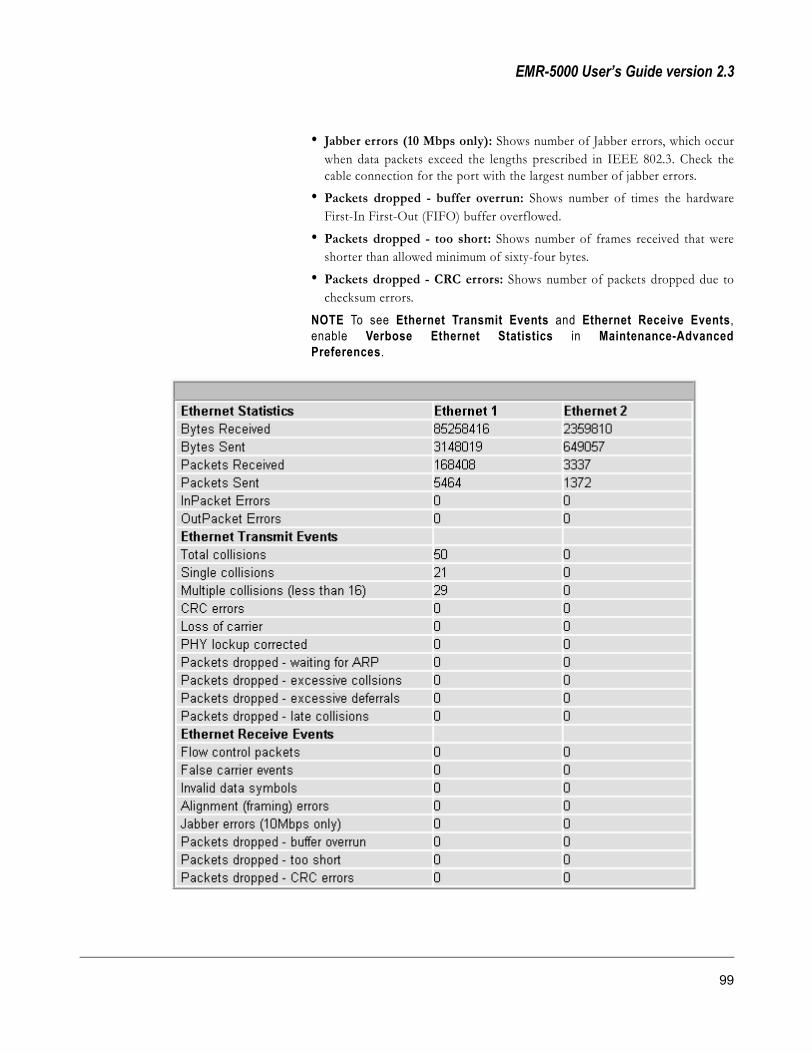
EMR-5000 User’s Guide version 2.3
• Jabber errors (10 Mbps only): Shows number of Jabber errors, which occurwhen data packets exceed the lengths prescribed in IEEE 802.3. Check thecable connection for the port with the largest number of jabber errors.
• Packets dropped - buffer overrun: Shows number of times the hardwareFirst-In First-Out (FIFO) buffer overflowed.
• Packets dropped - too short: Shows number of frames received that wereshorter than allowed minimum of sixty-four bytes.
• Packets dropped - CRC errors: Shows number of packets dropped due tochecksum errors.
NOTE To see Ethernet Transmit Events and Ethernet Receive Events,enable Verbose Ethernet Statistics in Maintenance-AdvancedPreferences.
99
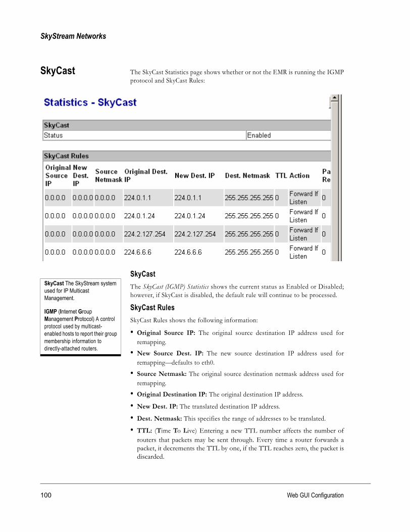
SkyStream Networks
SkyCast The SkyCast Statistics page shows whether or not the EMR is running the IGMPprotocol and SkyCast Rules:
SkyCastThe SkyCast (IGMP) Statistics shows the current status as Enabled or Disabled;however, if SkyCast is disabled, the default rule will continue to be processed.
SkyCast RulesSkyCast Rules shows the following information:
• Original Source IP: The original source destination IP address used forremapping.
• New Source Dest. IP: The new source destination IP address used forremapping—defaults to eth0.
• Source Netmask: The original source destination netmask address used forremapping.
• Original Destination IP: The original destination IP address.
• New Dest. IP: The translated destination IP address.
• Dest. Netmask: This specifies the range of addresses to be translated.
• TTL: (Time To Live) Entering a new TTL number affects the number ofrouters that packets may be sent through. Every time a router forwards apacket, it decrements the TTL by one, if the TTL reaches zero, the packet isdiscarded.
SkyCast The SkyStream system used for IP Multicast Management.
IGMP (Internet Group Management Protocol) A control protocol used by multicast-enabled hosts to report their group membership information to directly-attached routers.
100 Web GUI Configuration

EMR-5000 User’s Guide version 2.3
• Action: Forward, Forward If Listener, or Discard.
• Packets Received: Number of packets received from the satellite.
• Packets Processed: Number of packets forwarded to the network.
• Packets to Eth 1: Number of packets forwarded to Ethernet 1.
• Packets to Eth 2: Number of packets forwarded to Ethernet 2.
101
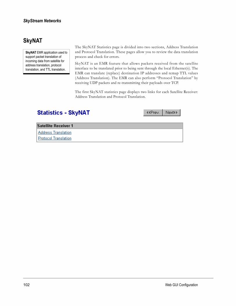
SkyStream Networks
SkyNATThe SkyNAT Statistics page is divided into two sections, Address Translationand Protocol Translation. These pages allow you to review the data translationprocess and check for errors.
SkyNAT is an EMR feature that allows packets received from the satelliteinterface to be translated prior to being sent through the local Ethernet(s). TheEMR can translate (replace) destination IP addresses and remap TTL values(Address Translation). The EMR can also perform “Protocol Translation” byreceiving UDP packets and re-transmitting their payloads over TCP.
The first SkyNAT statistics page displays two links for each Satellite Receiver:Address Translation and Protocol Translation.
SkyNAT EMR application used to support packet translation of incoming data from satellite for address translation, protocol translation, and TTL translation.
102 Web GUI Configuration

EMR-5000 User’s Guide version 2.3
Address Translation
The Address Translation Statistics page shows the following settings:
• Original and New Dest. IP Addresses: These settings show the originaldestination IP address, from where data was being transmitted, and the newIP address, where data is being routed.
• TTL (Time To Live) Translated TTL (zero means no change if Router Modeis enabled in Main ten ace Preferences).
• Netmask: This specifies the range of addresses to be translated.
• Packets Received and Packets Processed: Displays the amount of data thatis passing through the Address Translation process.
103

SkyStream Networks
Protocol Translation
The Protocol Translation Statistics page shows the following settings:
• Original Dest. IP Address: This is the address of the incoming UDP packetsto be translated.
• UDP and TCP Port: Shows the current Protocol UDP and TCP translationsettings. The SkyStream EMR changes UDP information into TCP packets tobe sent to the local network.
• Packets Received and Packets Processed: Displays the amount of data thatis passing through the Protocol Translation process.
104 Web GUI Configuration

EMR-5000 User’s Guide version 2.3
DHCP Server The DHCP Server Statistics page shows the current DHCP server information.The following information displays on the page:
Only Ethernet interfaces with static IP addresses assigned to them can beselected as DHCP Servers. Click the Ethernet interface you wish to view.
DHCP ServerThe DHCP Server Statistics shows the IP address, MAC address, and host name ofthe client. It also provides the lease time that these settings are valid.
IP Address: Shows the IP address of the client.
MAC Address: Shows the MAC address of the client.
Host Name: Shows the name given to the client.
Time to Expire: This value is the lease time shown in HH:MM:SS format, andshows how long these settings are still valid.
105

SkyStream Networks
PPPThe PPP Stat is t ics page shows the cur rent dial -up access infor mat ionconnecting a single computer to the Internet via modem. The followinginformation displays on the page:
PPP Statistics• Interface Status: “Active” or “Inactive”
• Dial Mode: “Dial on demand” or “Manual dial”
• Link Status: Physical link is “Up” or “Down.”
• Local IP Address: Shows the EMR IP address.
• Remote IP Address: Shows the ISP IP address.
• Subnet Mask: Shows EMR subnet mask.
• Connect Speed: Bits per second the modem connects at.
• Bytes Received: Shows bytes received through the modem.
• Bytes Sent: Shows bytes sent through the modem.
• Packets Sent: Shows packets sent through the modem.
• InPacket Errors: Shows number of errors in packets coming in.
• OutPacket Errors: Shows number of errors in packets going out.
• Collisions: Shows number of collisions while frame is being received.
PPP (Point-to-Point Protocol) A data link protocol that provides packet-oriented communication over serial lines.
106 Web GUI Configuration

EMR-5000 User’s Guide version 2.3
ISDN The Integrated Service Digital Network (ISDN) page shows the data beingtransmitted from point-to-point. The following information displays on thepage:
ISDN Statistics• Interface Status: “Active” or “Inactive”
• Dial Mode: “Manual” or “Dial on Demand”
• Local IP Address: This is the IP address of the local EMR.
• Remote IP Address: (Optional) not used in normal operation.
• Subnet Mask: Usually 255.255.255.255 for point-to-point connection.
• L2 Protocol: This is a Layer 2 protocol fixed at “HDLC.”
• L3 Protocol: This is a Layer 3 protocol fixed at “Synchronous PPP.”
• MRU: Set Maximum Receive Unit for negotiation (default 1500 bytes)
• MTU: Set Maximum Transmit Unit for negotiation (default 1500 bytes)
• Stream information: Bytes Sent, Bytes Received, Packets Sent, PacketsReceived, InPacket Errors, and OutPacket Errors.
107

SkyStream Networks
TCP Acceleration The TCP Acceleration Statistics page shows the status and number of TCPconnections made by the EMR. The following information displays on the page:
TCP Acceleration Statistics• Status Enabled/Disabled: TCP Acceleration status is enabled and ready to
make a connection or it can be disabled.• Number of current TCP connections: Displays the current number of TCP
connections.
108 Web GUI Configuration

EMR-5000 User’s Guide version 2.3
Sync The Sync Statistics page shows the HDLC frames received, processed, anddropped by the EMR. The following information displays on the page:
Sync Statistics• HDLC Frames Received: Number of frames received in synchronous
stream.• HDLC Frames Processed: Number of frames processed by data pipe
packetizer.• HDLC Frames Dropped: Number of frames dropped because of failed
assembly.
HDLC (High-level Data Link Control) An ISO communications protocol used in X.25 packet switching networks. It provides error correction at the data link layer.
109

SkyStream Networks
Turbo Internet/VPN The Turbo Internet/VPN Statistics page shows the status of Point-To-PointTunneling Protocol (PPTP), IPSec General Statistics, IKE Security Associationand IPSec Security Associations in the EMR. The following information displayson the page:
NOTE Only one connection method may be used at a time with TurboInternet/VPN. If PPTP is connected, IPSec is disconnected, and vice-versa. Ifneither is connected, this page will show disconnected status for both.
110 Web GUI Configuration

EMR-5000 User’s Guide version 2.3
PPTP Statistics• Status: “Connected” or “Disconnected”
• PPTP Server: IP address of server of Windows PPTP server or VPNconcentrator.
• Encryption Method: This release supports Microsoft Point-to-PointEncryption (MPPE), MSCHAP-v1 and v2. This release also supports PAPwith no encryption.
NOTE MPPE uses RC4, a stream cipher, to encrypt the PPP datagrams. Itcurrently supports encryption keys of 40 and 128 bits.• Mode: “stateless encryption” or “non-stateless encryption”
NOTE In stateless mode, the encryption keys are changed on every packet. Innon-stateless mode, the same key is used for many packets. Stateless modeis more reliable in “lossy” networks, and is more resistant to certain types ofcryptographic attacks. Non-stateless mode is a slightly more efficient methodin reliable networks.• Key Length: “40-bits” or “128-bits”
• Connection Time: Time in hours, minutes, and seconds (HH:MM:SS) formatsince the connection was established.
• Local Tunnel IP Address: IP address on the EMR side.
• Remote Tunnel IP Address: IP address on the server side.
• Subnet Mask: Usually 255.255.255.255, since this is a point-to-pointconnection.
• Stream information: Bytes Received, Bytes Sent, Packets Received, PacketsSent, InPacket Errors, OutPacket Errors, and Collisions.
111

SkyStream Networks
IPSec General Statistics
• Status: “Connected” or “Disconnected”
• IPSec Gateway: IP address of remote gateway or VPN concentrator.
• Stream information: Combined total Bytes Received, Bytes Sent, PacketsReceived, Packets Sent, InPacket Errors, OutPacket Errors, and Collisions forall IPSec Security Associations.
IP Sec The IP security protocol, more commonly known as IPsec, is a suite of protocols that provides security at the network layer.
112 Web GUI Configuration

EMR-5000 User’s Guide version 2.3
IKE Security Associations• Gateway: IP address of the other side of the IPSec connection. Usually a
VPN server.• Security: Combination of encryption, authentication and key exchange
parameters currently used for this connection.• IKE Lifetime: Time (HH:MM:SS) for which the IKE Security Association
(SA) remains valid.
• IPSec Lifetime: Time (HH:MM:SS) for which the IPSec SA remains valid.
• Serial Number: A unique identifier associated with the IKE SA, whichusually increments each time the SA is re keyed.
NOTE IKE negotiation happens first to create an authenticated encryptionchannel. This channel is then used to negotiate an IPSec SecurityAssociation (SA) between two gateways. The IPSec SA is then used totransfer encrypted and authenticated data traffic between the gateways andany subnets that might be configured.
IPSec Security Associations• Direction: “Out” or “In”
NOTE IPSec tunnels are unidirectional.• Tunnel Endpoint: Termination point (IP address) of a tunnel. This will
usually be the IP address of EMR or the remote IPSec gateway.
• Security: IPSec protocol, encryption, and authentication currently used forthis connection.
• Source: The source address of packets that will use these tunnels.
• Destination: The destination address of packets that will use these tunnels.
• Packets: Number of packets sent or received via this tunnel.
• Uptime: Amount of time this tunnel has been in operation.
113

SkyStream Networks
Multifrequency Settings
The Multifrequency Statistics page will display if it is set in E-Manager. It willexist as long as Multifrequency logic is searching for a lock. Once it has acquiredlock, the information will go away.
Set 1 and Set 2The values follow are the same as in Satellite Receiver Statistics.
StatusThe status will reflect the controls for obtaining lock configured in E-ManagerConfiguration—Satellite Receiver, Multifrequency Properties.
E-Manager Multifrequency Properties
The following parameters are set in E-Manager to obtain lock after you haveconfigured two sets of frequencies.
Set Immediately: Tries to Set-1 first for lock-on and if it fails will try Set-2 in Continuous Mode.
Set upon loosing lock: Tries to trigger change over from one configuration to another when lock is lost.
Interval gives the time in seconds it tries to get lock. When continuously trying to get lock.
Click the Advanced button and set the Timeout in minutes, which is the time set for acquiring lock.
114 Web GUI Configuration

EMR-5000 User’s Guide version 2.3
ConfigurationSatellite Receiver
The Satellite Receiver Configuration page allows you to control Satellite Receiversettings. The first page displays the Satellite Receivers present in the EMR. Byclicking the applicable link, you can access the Tuner page for each SatelliteReceiver.
115

SkyStream Networks
TunerThe first configuration page provides current information on the satellite receiver,such as LNB Mode status, Symbol Rate, L-BAND Frequency, LNB VoltageControl (polarization, 22kHz Switch status, and Data Lock (FEC lock) status. Youcan also change the LNB Mode by selecting one of the radio buttons (None,Single, and Double) or you can change the configuration by clicking the ChangeTuner Settings button. This wi l l open the other boxes for configurationpurposes. Once you have completed the configuration, you must click the Applybutton. You can then view Satellite Receiver Statistics by clicking the View TunerStatistics button. In addition, you can configure Multifrequency Settings.
Change Tuner SettingsYou can configure the following fields on the Configuration Satellite Tuner pagefor Receiver 1:
Symbol Rate: Sets a value for the symbol rate received from the satellite tunerin megasymbols.
NOTE The symbol rate values can be displayed as Msymbols/s or ksymbols/s. This value can be set in the Maintenance Preference page.LNB Mode: Select the radio button to set the LNB settings.
� None: Use if no LNB is present.� Single: Use if a single LNB is installed; when selected, enter the frequency in
gigahertz (GHz).� Dual: Use if dual LNBs are installed; when selected enter the High and Low
frequencies in gigahertz (GHz).
116 Web GUI Configuration
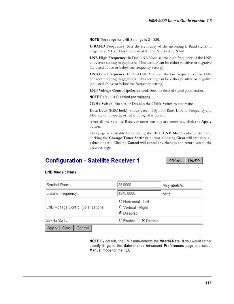
EMR-5000 User’s Guide version 2.3
NOTE The range for LNB Settings is 3 - 220.L-BAND Frequency: Sets the frequency of the incoming L-Band signal inmegahertz (MHz). This is only used if the LNB is set to None.
LNB High Frequency: In Dual LNB Mode set the high frequency of the LNBconverter setting in gigahertz. This setting can be either positive or negative(adjusted above or below the frequency setting).
LNB Low Frequency: In Dual LNB Mode set the low frequency of the LNBconverter setting in gigahertz. This setting can be either positive or negative(adjusted above or below the frequency setting).
LNB Voltage Control (polarization): Sets the desired signal polarization.
NOTE Default is Disabled (no voltage).22kHz Switch: Enables or Disables the 22kHz Switch to automatic.
Data Lock (FEC lock): Shows green if Symbol Rate, L-Band Frequency andFEC are set properly, or red if no signal is present.After all the Satellite Receiver tuner settings are complete, click the Applybutton.
This page is available by selecting the Dual LNB Mode radio button andclicking the Change Tuner Settings button. Clicking Clear will initialize allvalues to zero. Clicking Cancel will cancel any changes and return you to theprevious page.
NOTE By default, the EMR auto-detects the Viterbi Rate. If you would ratherspecify it, go to the Maintenance-Advanced Preferences page and selectManual mode for the FEC.
117

SkyStream Networks
Multifrequency SettingsMultifrequency allows you to reconfigure EMR satellite information remotelythrough using two sets of frequency-satellite parameters by which the EMRmight achieve lock. First , the EMR tries to acquire lock with one set ofparameters, and if it fails, tries a second set.
Click the Multifrequency Settings button in the Tuner Configuration page andthe following page will display:
To configure Set 1, click the Configure Set 1 button. Depending upon whichLNB Mode you select, a different dialog box will appear. Enter settings in thesame ways as configuring Satellite Receiver and click Apply. Then configure Set2 in the same way. Click the Advanced button to set the method by which theEMR obtains lock. When you are ready, click the Start Multifrequency button.
118 Web GUI Configuration

EMR-5000 User’s Guide version 2.3
Advanced SettingsAfter configuring Advanced Multifrequency Settings, click Apply.
Type: Select the type of method for obtaining lock; either Set Immediately orSet upon losing lock. In this way, one set will become the first set applied,followed by the second set of parameters.
Interval: Type the interval in seconds that the tuner checks to see if it has lostlock.
Timeout: Type the period in minutes that a set of paramteres tries to obtainlock and/or checks the tuner status to make sure that the tuner has lock.
The default is zero [0], which means that it will try forever until it acquires lock.
Lock means that a signal, data or other information is being recieved and processing properly.
119

SkyStream Networks
Network Interface The Network Interface page allows you to modify the network setting on theEthernet and Satellite Receiver Interfaces.
The first page that appears shows the available Ethernet interfaces on theSkyStream EMR. By clicking the link for Ethernet 1, Ethernet 2, SatelliteReceiver 1, or Satellite Receiver 2, the following pages appear:
To configure the Ethernet interface:
Select either “Obtain IP Address from DHCP Server” or “Specify an IPAddress” depending on your local network configuration.
If you selected to specify an IP address:
1 Enter the IP address.
2 Enter the subnet mask information.
3 Click the Apply button to save the changes.
120 Web GUI Configuration

EMR-5000 User’s Guide version 2.3
DHCP Client RequirementsThe DHCP client must be able to acquire the following information:
• IP Address
• Subnet Mask
NOTE Because the SkyStream EMR is primarily a router, the DHCP client willnot set DNS server and domain name information, as DNS lookups may slowdown the unit. The DHCP client will only request the three parameters listedabove.You can configure Ethernet 2 in the same manner as Ethernet 1.
To configure the Satellite Receiver Interfaces:
Satellite interfaces only require an IP address and subnet mask.
121

SkyStream Networks
PID Selection Packet IDs (PIDs) are identifiers used to tag different MPEG packet flowsinside the transport stream. The SkyStream EMR uses PIDs to identify thedifferent broadcast data or programs in the broadcast streams. In order toreceive specific data, the correct PID must be entered. The EMR can handle 32to 64 PIDs for each satellite receiver.
Clicking the Satellite Receiver 1 PID Selection link will take you to the nextpage.
122 Web GUI Configuration

EMR-5000 User’s Guide version 2.3
To scan for all PIDs in the stream:
1 Select the Enable PID Scanning radio button and click Apply. This actionstops data traffic and displays all detected PIDs in the stream when you pressRefresh.
2 When scanning is complete, you should select the Disable radio buttonbecause this function has high CPU Usage. If you want to add a PID intoActive PIDs, select the PID from the Scanned PIDs list and click the Addbutton.
To add a New Active PID:
1 First select either Decimal or Hexadecimal, depending on the format youwant to use when entering PID values.
TIP A block of PIDs can be entered as follows: 200,300-320,500. This will add PIDs 200, 500 and 300 through 320 to the list of active PIDs.
2 Enter the PID value, range between 0 and 8191 (0x and 0x1FFF) to New PIDbox.
3 Click the Add button.
4 To delete an existing PID, click the Delete link next to the PID.
NOTE To see Bits/Sec for Active PIDs, enable PID Rate Monitoring inMaintenance Preferences.
123

SkyStream Networks
MAC Address Selection
Each satellite receiver card has a unique MAC Address assigned by SkyStream.In normal operation, the satellite receiver will only accept unicast packets wherethe destination MAC addresses matches that of the receiver. Using this page, youcan define up to 32 additional MAC addresses per receiver. Incoming unicastpackets matching any of these addresses will be accepted and forwarded. Youcan also disable MAC address filtering.
The first page that appears shows the satellite receivers connected to the EMR.Clicking the link will take you to a page where you can add or delete a MACaddress.
124 Web GUI Configuration

EMR-5000 User’s Guide version 2.3
MAC Addresses can be added or deleted on this page. The MAC Configurationpage shows a l l the cur rent MAC addresses in use. You can also EnablePromiscuous Mode, which means that the EMR accepts all MAC addresses; oryou can Disable Promiscuous Mode, which means that the EMR only acceptsthe listed MAC addresses plus the default receiver MAC addresses. After makingchanges, click Apply.
To add a new MAC Address:
1 Type the New MAC Address. Use hexadecimals separated by colons, spaces,or dashes.
2 Click the Add button.
3 To cancel the MAC Address, click the Delete link.
125

SkyStream Networks
Static Routes This page allows you to add static routes to the system. The first page alsoprovides information on current static routes.
Enter any additional routing option(s) in the first box. This will allow you tocontrol the infor mation retrieved by the Route function. For addit ionalinformation on routing options, click the More Info button. This will display adocument defining the route command.
OR SEE Appendix A: Command Definitions
126 Web GUI Configuration

EMR-5000 User’s Guide version 2.3
Current Static RoutesClick the Add New Route button and the next page will appear. This pageallows you to configure a new route.
Select the interface type using the radio option button for Network, Host, orDefault Gateway, then click the Apply button to save settings. To reset the routeconfiguration page, click the Cancel button. Enter the IP address, netmask, andgateway network information for the route utility. Type a metric value for thisroute. If you do not enter a value, the default value is 1. After you haveconfigured the route settings, click the Apply button.
Click View Current Routing Table button and the following page will display:
RIP V1The RIP V1 section allows you to configure and enable/disable RIP (RoutingInformation Protocol). RIP allows the EMR to exchange routing informationwith neighboring routers and automatically learn the network topology. Use theradio buttons to enable/disable RIP. If RIP is enabled, you can use the radiobuttons to export (announce) the default route, if the EMR has one. After youhave configured the settings, click the Apply button.
127

SkyStream Networks
SkyCast You can enable or disable SkyCast from the Configuration SkyCast page andthen apply new rules. Moreover, you can enable or disable Global source re-address, which re-addresses the IP address of all packets regardless of group oraddress. Click Apply to make effective.
The EMR has the following multicast processing functionality (SkyCast):
• Forwarding: a particular multicast group may be unconditionally forwarded,discarded, or conditionally forwarded if listeners are in the network.
• Remapping: multicast addresses and TTL can be optionally remapped to newvalues.
NOTE When remapping a source IP address, not all fields in the SkyCast rule need to befilled. If the intention is just to remap the Source IP Address then it is only necessary toenter values in the first three fields—Original Source IP, New Source Dest. IP, and SourceNetmask.
Global Source Re-addressIf you enable Global Source Readdress, the source IP address of all packets witha multicast destination will be remapped to eth0, eth1, or both depending onwhichever one has been a listening member joining the multicast group. Inaddition, it will use the SkyCast default rule for TTL and forwarding.
128 Web GUI Configuration

EMR-5000 User’s Guide version 2.3
NOTE If SkyCast is enabled, then the source map will first try to process therules in SkyCast and then process global source remapping. If the user onlywants to use the default rule—with global source IP remap enabled—andbypass the SkyCast rules, then the user can disable SkyCast.
SkyCast RulesSkyCast Rules allow you to add, edit or delete SkyCast rules from the system.SkyCast rules also allow you to apply specific guidelines on how the informationis sent to the local network.
This section describes how to configure the multicast functionality.
• To configure the system, enter the Original Dest. IP Address, NewDestination IP Address, Netmask, TTL settings, and the Action rule forforwarding streams.
Configure SkyCastTo edit current rules or the default rule information, click the Edit link. Todelete a Current Rule, click the Delete link next to it. To add a new SkyCastRule, click the Add New Rule button.
Enter the following information to add a new SkyCast Rule:
129

SkyStream Networks
• Original Source IP Address, New Source IP Address, and SourceNetmask (Optional): These three settings are used to remap the Source IPaddress.
• Original and New Destination IP Addresses: These settings are theOriginal Destination IP Address of a data stream to be sent to a NewDestination IP Address.
• Netmask: The netmask specifies the range of addresses to be translated. Forexample, a netmask of 255.255.255.255 represents only one address, while anetmask of 255.255.255.0 represents a range of 256 addresses. Example: IfOriginal Dest. IP Address is 224.1.1.0, Netmask is 255.255.255.0 and NewDest. IP Address is 225.1.1.0, then packets destined to 224.1.1.1 willtranslate to 225.1.1.1, packets to 224.1.1.2 translate to 225.1.1.2, and so on upto 224.1.1.255 translating to 225.1.1.255.
• TTL (Time To Live) If you leave this value at zero, the TTL remainsunchanged.
NOTE The default for the TTL value is zero (0). This is a special value used toindicate that the EMR will not change the TTL value as it forwards thepackets. If you leave this value at zero the TTL remains unchanged; however, this onlyapplies if Router Mode is enabled in Maintenance Preferences.• Action: The Action radio buttons allow you to set up a specific Forwarding
Rule for the specified multicast IP address. The following three options areavailable:
� Forward If Listener: Sends the multicast packets from this multicast group intothe network if there is a group member present.
� Discard: Discards all packets belonging to this group.
� Forward: Sends the Multicast packets into the local network unconditionally;however, you will need to select which Ethernet to Forward through using theradio buttons (Ethernet 1, and Ethernet 2).
• Change: To delete a rule, click the Delete link. To edit a rule, click the Editlink.
TTL (Time To Live) Entering a new TTL number affects the number of routers that packets may be sent through. Every time a router forwards a packet, it decrements the TTL by one, if the TTL reaches zero, the packet is discarded. The TTL settings can vary depending on the topology of the local network to attempt to keep streams from being forwarded outside of your network.
130 Web GUI Configuration

EMR-5000 User’s Guide version 2.3
NOTE The same procedure applies to Default Rules. However, the defaultrules, in addition to the remapping addresses, only contain OriginalDestination IP, Netmask, and TTL.
131

SkyStream Networks
SkyNAT The SkyNAT Configurat ion page is divided into two sect ions, AddressTranslation and Protocol Translation. These pages allow you to configure thedata translation process. To activate this option, click the Enable radio buttonand then click the Apply button. To turn it off, select the Disable radio buttonand click the Apply button.
Address TranslationClick the Address Translation link to access the configuration page.
The Address Translation page shows the following settings:
• Original and New IP Addresses: These indicate the original destination IPaddress of the packets to be translated. Packets received on the DVB interfacethat match the original IP address range are transmitted with the new IPaddress as their destination.
• Netmask: This specifies the range of addresses to be translated.
• TTL (Time To Live) If you leave this value at zero, the TTL remainsunchanged; otherwise, the new TTL value is set.
• Change: To delete a rule, click the Delete link.
NOTE This release supports 100 Address Rules.
132 Web GUI Configuration

EMR-5000 User’s Guide version 2.3
To add new SkyNAT Address Translation options, click the Add New Rulebutton. A new page will appear, enter the information for the New AddressTranslation Rule.
133

SkyStream Networks
Protocol TranslationClick the Protocol Translation link to access the configuration page.
The Protocol Translation page shows the following settings:
• Original Dest. IP Address: Indicates the original destination IP address forUDP packets to be subject to translation. Only UDP packets with thisdestination address will have their payloads translated.
• UDP Port: Indicates the original UDP destination port for translated packets.
• TCP Port: The EMR will listen to incoming TCP connections on this port todeliver the packet payloads.
To add new SkyNAT Protocol Translation options, click the Add New Rulebutton.
• Original Dest. IP Address: Indicates the original destination IP address forUDP packets to be subject to translation. Only UDP packets with thisdestination address will have their payloads translated.
• UDP Port: Indicates the original UDP destination port for translated packets.
• TCP Port: The EMR will listen to incoming TCP connections on this port todeliver the packet payloads.
To save these options, click the Apply button.
NOTE TCP and UDP port numbers are between 0 and 65535.
134 Web GUI Configuration

EMR-5000 User’s Guide version 2.3
DHCP Server The DHCP Configuration page allows you to set up the DHCP Server settings.To configure the Server settings enter the Domain name, DNS server(s), Subnetmask, Lease Time, Default Broadcast Address, Router(s), and address ranges tobe assigned to listeners in the appropriate boxes on the configuration page. Toapply the setting, click the Apply button. You can also view DHCP ServerStatistics.
The following information gives you details about the different configurationsfor DHCP Client and Server settings.
135
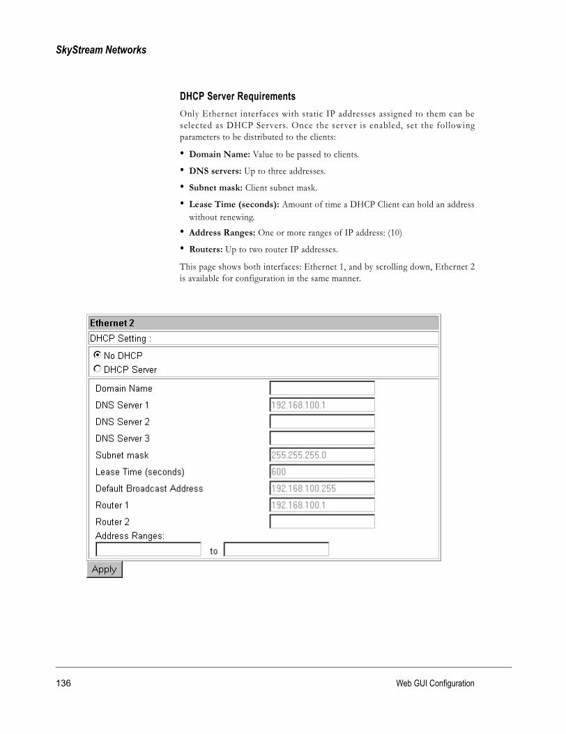
SkyStream Networks
DHCP Server RequirementsOnly Ethernet interfaces with static IP addresses assigned to them can beselected as DHCP Servers. Once the server is enabled, set the fol lowingparameters to be distributed to the clients:
• Domain Name: Value to be passed to clients.
• DNS servers: Up to three addresses.
• Subnet mask: Client subnet mask.
• Lease Time (seconds): Amount of time a DHCP Client can hold an addresswithout renewing.
• Address Ranges: One or more ranges of IP address: (10)
• Routers: Up to two router IP addresses.
This page shows both interfaces: Ethernet 1, and by scrolling down, Ethernet 2is available for configuration in the same manner.
136 Web GUI Configuration

EMR-5000 User’s Guide version 2.3
SNMP SNMP (Simple Network Management Protocol) is a widely used networkmonitoring and control protocol.
To configure the SkyStream EMR for SNMP, enter the following information:
• Trap Destination: Enter the IP address to be used for the trap destination.
• Trap Community: Sets the trap community name to be used with this levelof access.
• SNMP Community: Enter the SNMP community name to be used with thisaccess level.
• Access Control: Defines this access level for this community. SelectRead_Only or Read_Write from the pull down box. Allows Write or Readonly access to the SNMP function.
• Click the Add button to apply the SNMP settings.
• Click the Edit or Delete link next to the SNMP section in order to modify orremove the SNMP settings.
137
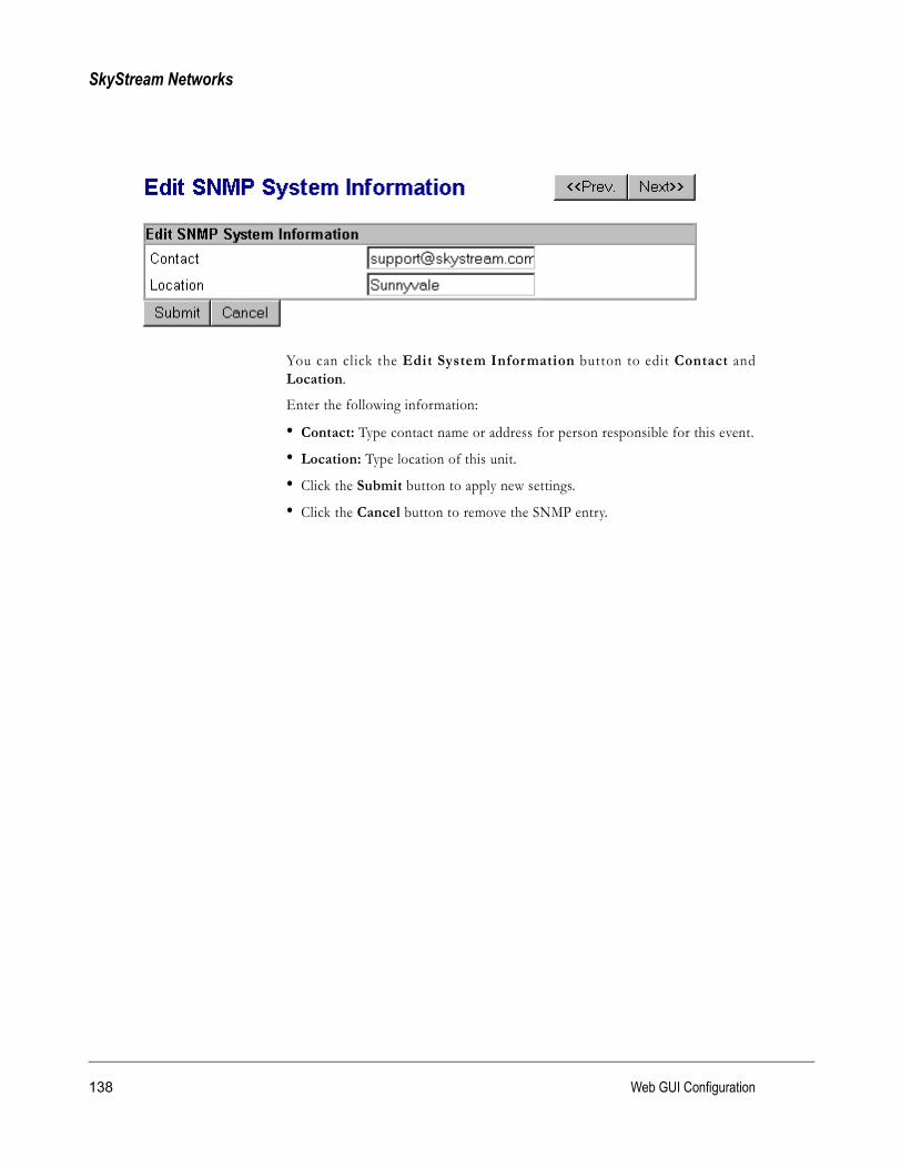
SkyStream Networks
You can cl ick the Edit System Information button to edit Contact andLocation.
Enter the following information:
• Contact: Type contact name or address for person responsible for this event.
• Location: Type location of this unit.
• Click the Submit button to apply new settings.
• Click the Cancel button to remove the SNMP entry.
138 Web GUI Configuration

EMR-5000 User’s Guide version 2.3
PPP Point-to-Point Protocol is a data link protocol that provides dial-up access overserial lines connecting a single computer to the Internet via a modem.
To configure the SkyStream EMR for PPP, you must enter connect ioninformation into the following tabs: ISP/Remote PPP Server Setup, NetworkSetup, Hardware Settings, Modem Settings, and Demand Dialer.
The button Enable/Disable toggles PPP “on” or “off ” and the Connect/Disconnect button toggles Manual Dialing “on” or “off.” You can also ViewPPP Statistics.
NOTE These values are set per EMR and are not saved in a configuration file.
139

SkyStream Networks
ISP/Remote PPP Server Setup
Click the ISP/Remote PPP Ser ver Setup tab and enter the fol lowinginformation:
• Phone Number: Type phone number of remote ISP server. If your systemrequires you to dial ‘9’ for an outside line, type ‘9<comma>’ and phonenumber without spaces.
• User Name: Type User Name required to log-on to remote ISP.
• Password: Type password to log-on to remote ISP.
Click Advanced button to set up Expect/Send Strings or turn Debug on oroff. Click Apply button or click Cancel to remove the entry.
PAP (Password Authentication Protocol) The most basic access control protocol for logging onto a network. A table of usernames and passwords is stored on a server. When users log on, their usernames and passwords are sent to the server for verification.
140 Web GUI Configuration

EMR-5000 User’s Guide version 2.3
Advanced ISP/Remote PPP Server
Expect/Send Strings
Generally, a script consists of one or more “expect/send” pairs of strings,separated by spaces, with an optional “subexpect-subsend” string pair, separatedby a dash as shown in the illustration. What you expect to receive in your logonscript is in the Expect box, and what you would type to log on is in the Sendbox. You must be an advanced user to use this feature. If you have had difficultyconnecting to your ISP, you can check the Log File for possible connectionerrors.
Debug On/Off
To view the Log File, click the Debug on radio button and click Apply, thenclick the View Log button. For more information, consult your service providerfor documentation on “hooking up a PPP link to an Internet Ser viceProvider (ISP).”
141

SkyStream Networks
Network Setup
Click the Network Setup tab and enter the following information:
• Use Peer as Default Route: Toggle radio buttons for modem-side gateway.
• Maximum Receiver Unit (MRU): 1500 (default) bytes
• Maximum Transmit Unit (MTU): 1500 (default) bytes
• Connect Timeout: PPP connection timeout (default is 45 seconds).
Click Apply button or click Cancel to remove the entry.
Click Advanced button to set up Local IP Address or Remote IP Address.
• Local IP Address: Type the EMR IP address (0.0.0.0 will negotiate actualIP address during connection).
• Remote IP Address: Type ISP IP address (optional)
Click Apply button or click Cancel to remove the entry.
MRU (Maximum Receive Unit)The largest packet size that canbe received over the network.
MTU (Maximum TransmissionUnit) The largest packet size thatcan be transmit ted over thenetwork. Messages longer thanthe MTU must be divided intos m a l l e r p a c k e t s b y t h ecommunications protocol.
142 Web GUI Configuration

EMR-5000 User’s Guide version 2.3
Hardware Settings
Click the Hardware Settings tab and enter the following information:
• Line Speed: Select line speed (baud rate of the modem)
• Modem Type: Select Internal or External modem (this line only appears ifthe EMR has an internal modem).
• Hardware Flow Control: Toggle radio buttons between Enable and Disable.
Click Apply button or click Cancel to remove the entry.
143

SkyStream Networks
Modem Setup
Click the Modem Setup tab and enter the following information:
• INIT String: ATZ ATE1VE1V1Q0 (default) Initial string of up to 256characters. You can override this setting with a new initializing string.
• Dial String: ATDT (default) Dial string of 8 characters.
Click Apply button or click Cancel to remove the entry.
Modem Setup for External ISDNYou can use an external ISDN through the PPP page with some modification onthe AT string, the new INIT string for using external ISDN would be as follows:
INIT String: ATE0V1Q0&D2!D1=57600%A2=96&K3
The explanation for this new AT string is as follows:
� ATE0 - Echo Off
� ATV1 - Result Code format (long format)
� ATQ0 - Enable Result Codes
� AT&D2 - DTR Control
� AT!D1= - Specify Default DTE Speed (n=speed)
� AT%A2= - Protocol Control (n=95 for async to sync conversion , n=96 for MLPPP)
� AT&K3 - Enable RTC CTS
144 Web GUI Configuration

EMR-5000 User’s Guide version 2.3
Demand DialerThe Demand Dialer is your gateway to remote ISP/PPP servers. The Idletimeout at the top of the Demand Dialer page allows you to specify the time inseconds before the dialer hangs up. Click the Demand Dialer tab to connect,view, edit, and delete rules.
145

SkyStream Networks
You can create a new rule by clicking the New Rule button at the bottom of thepage and click the New day/time button to set up dialing rules. After you haveconfigured the Demand Dialer rule, click Apply button. The Advanced buttonprovides a way to “ignore” all packets received on a given interface.
Advanced ButtonThis feature provides a way to “ignore” all packets received on a given interface,and can be used to prevent demand dial if spurious traffic is expected on aparticular interface. This is useful if you have Promiscuous MAC enabled, anddo not want unexpected packets to trigger a dial. The packets are still processedas usual; however, they will not cause an automatic dial even if they match one ofthe “accept” rules. By default, packets received by the Satellite Receiver(s) areignored by the demand-dial and demand-tunnel rules. This can be changed byclicking the receiver checkboxes and clicking Apply.
146 Web GUI Configuration

EMR-5000 User’s Guide version 2.3
Click Edit or Add New Rule and enter the following information:
• Action: Select from list “accept,” or “ignore.”
• Protocol: Select from the following list: TCP, UDP, ICMP, IGMP, EGP, GRE,IPv6-in-IPv4, ESP, AH, or any protocol.
NOTE Only TCP and UDP may use port numbers.• Source IP Address: The dialer source IP address
• NetMask: The dialer source netmask
• Destination IP Address: The dialer destination IP address
• Netmask: The dialer destination netmask
• Source Port (0 for any): The dialer source port number. Type zero ‘0’ for anyport.
• Destination Port (0 for any): The dialer destination port number. Type zero‘0’ for any port.
IPv6-in-IPv4 A next-generation Internet Protocol, known first as IPng and then as IPv6, has been under development by the Internet Engineering Task Force (IETF) for several years to replace the current Internet Protocol known as IPv4.
147

SkyStream Networks
Click New day/time button and enter Start Time and End Time. You can alsoselect specific days in that time period.
NOTE No New day/time rule can cross the boundary of a day. The first scenario shows that a New date/time rule cannot be set past 11.59 PM(actually 11:59:59). To continue into the following day, you must create a secondrule that starts the next day starting at midnight (12.00 AM).
The second scenario shows how two rules allow you to dial at anytime except forone hour from noon to 1.00 PM. To achieve this, you must create one rule thatstarts, say, at midnight and finishes at 11.59 AM and another that starts at 1.00PM and ends at 11.59 PM. This will block off one hour starting at noon.
148 Web GUI Configuration
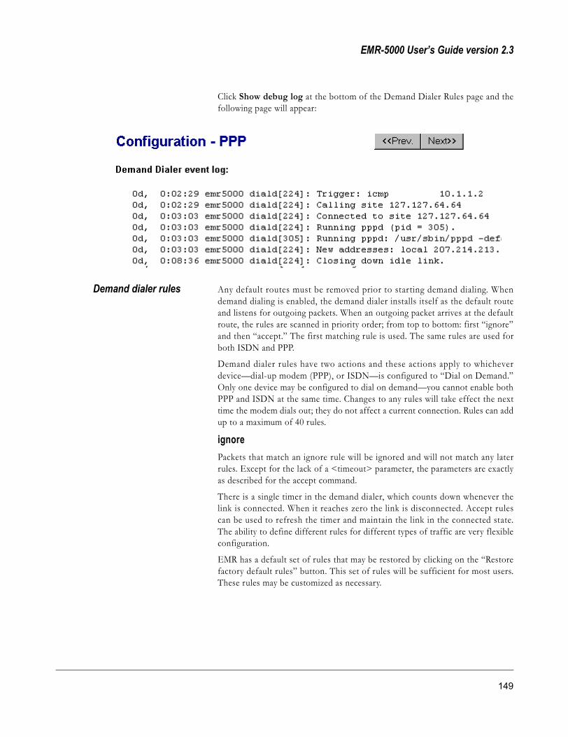
EMR-5000 User’s Guide version 2.3
Click Show debug log at the bottom of the Demand Dialer Rules page and thefollowing page will appear:
Demand dialer rules Any default routes must be removed prior to starting demand dialing. Whendemand dialing is enabled, the demand dialer installs itself as the default routeand listens for outgoing packets. When an outgoing packet arrives at the defaultroute, the rules are scanned in priority order; from top to bottom: first “ignore”and then “accept.” The first matching rule is used. The same rules are used forboth ISDN and PPP.
Demand dialer rules have two actions and these actions apply to whicheverdevice—dial-up modem (PPP), or ISDN—is configured to “Dial on Demand.”Only one device may be configured to dial on demand—you cannot enable bothPPP and ISDN at the same time. Changes to any rules will take effect the nexttime the modem dials out; they do not affect a current connection. Rules can addup to a maximum of 40 rules.
ignorePackets that match an ignore rule will be ignored and will not match any laterrules. Except for the lack of a <timeout> parameter, the parameters are exactlyas described for the accept command.
There is a single timer in the demand dialer, which counts down whenever thelink is connected. When it reaches zero the link is disconnected. Accept rulescan be used to refresh the timer and maintain the link in the connected state.The ability to define different rules for different types of traffic are very flexibleconfiguration.
EMR has a default set of rules that may be restored by clicking on the “Restorefactory default rules” button. This set of rules will be sufficient for most users.These rules may be customized as necessary.
149

SkyStream Networks
accept Packets that match an accept rule will cause the link to come up and/or stay upfor at least <timeout> seconds. The value <timeout> must be a non-negativeinteger. A <timeout> of zero means the connection associated with the packetwill be killed immediately. The default is 300 seconds.
The following debugging method will assist you in the development of customrule sets and to diagnose problems with demand-dial connections. The “Showdebug log” button displays a log file that indicates the activity of the demanddialer. Each time a demand rule causes the EMR to dial out, a “Trigger” messagewill appear in the log. This trigger message indicates the original source,protocol, source address (and port), and destination address (and port) of thematching packet that initiated the connection.
Trigger: from locally generated: tcp 192.168.4.178/1044 64. 165.192.147/1723
The above trigger is an example of an EMR initiating a PPTP connection to aPPTP server at 64.165.192.147, port 1723
The source of the packet that caused the trigger can be one of the following:
locally generated — a packet that originated from EMREMR itself.
eth1 — a packet that was received on Ethernet-1
eth2 — a packet that was received on Ethernet-2
satrx1 — a packet that was received on Satellite Receiver-1
satrx2 — a packet that was received on Satellite Receiver-2
This debugging message makes it easier for you to know what caused themodem to dial when configured for demand dialing. This allows you to adjustdemand rules if necessary.
If a timeout expires and causes the disconnection of the link, a message like theone below will appear in the log:
Closing down idle link
150 Web GUI Configuration

EMR-5000 User’s Guide version 2.3
ISDN Integrated Service Digital Network (ISDN) allows data to be transmitted frompoint-to-point and reach a destination without errors. The rate of transmissionof the data in the ISDN is 64 kbps per channel (maximum 128 kbps). The EMRsupports BRI, passive, with two B-channels.
NOTE Even without an ISDN card, it is still possible to use an external ISDNthrough PPP. See PPP Modem Setup.
To configure the EMR ISDN, you must enter connection information into thefollowing tabs:
NOTE These values are set per EMR and are not saved in a configuration file.
� ISP/Remote ISDN Server Setup
� ISDN-PPP Setup
� ISDN Line Settings
The Manual dial now button, at the bottom of the main ISDN configurationproperties page, causes the EMR to immediately dial out using the currentlyconfigured phone number, username, and password. Alternatively, clicking theDial on demand button causes the EMR to dial out only when necessary. Thedecision to dial out and the amount of time to stay connected are controlled by a
151

SkyStream Networks
set of demand dialer rules. You can configure the demand dialer rules by clickingon the menu tab Demand Dialer. See Demand dialer rules.
ISP/Remote ISDN Server Setup
Click the ISP/Remote ISDN Ser ver Setup tab and enter the fol lowinginformation:
• Phone Number: Type phone number of remote ISP server.
• User Name: Type User Name required to log-on to remote ISP.
• Password: Type password to log-on to remote ISP.
152 Web GUI Configuration

EMR-5000 User’s Guide version 2.3
ISDN-PPP Setup
Click the ISDN-PPP Setup tab and enter the following information:
• Use ISDN Connection As Default Route: Toggle “Yes” or “No”
• VJ Header Compression: Toggle “Enable” or “Disable.” This setting allowsyou to enable or disable Van Jacobson style TCP/IP header compression.
• B Channel (Multilink PPP): Select “One B-Channel” or “Two B-Channels”
• Maximum Receiver Unit (MRU): 2000 (default) bytes
• Maximum Transmit Unit (MTU): 1500 (default) bytes
• IP Address Negotiation: Toggle “Enable” or “Disable.”
• Requested IP Address: Type the EMR IP address (0.0.0.0 will negotiateactual IP address during connection).
• Remote IP Address: Type remote ISP IP address (optional)
Click Apply button or click Cancel to remove the entry.
153

SkyStream Networks
ISDN Line Settings
ISDN Line Settings• D-Channel Protocol: Select from the following list: Protocol 1TR6, Protocol
EDSS1, Protocol Leased, and Protocol NI1.
Line numbers• MSN/EAZ1 and 2: Multiple Subscriber Number or Endgeraete Auswahl
Ziffer (Germany) Obtain these numbers from your Internet Service Provider.• SPID 1 and 2: Service Profile Identifier is an additional identifier used to
identify the EMR ISDN device to the telephone network. Obtain thesenumbers from you Internet Service Provider.
NOTE SPID is available by selecting Protocol NI1 as the D-Channel Protocol.
154 Web GUI Configuration

EMR-5000 User’s Guide version 2.3
Demand DialerThe Demand Dialer is a tool which allows the EMR to dial out only whennecessary. The decision to dial out and the amount of time to stay connected arecontrolled by a set of demand dialer rules. When a packet arrives at EMR and noroute exists for the destination IP address, the demand dialer will compare thepacket against the set of rules. The first matching rule is used to determine if thedemand dialer should dial out or remain connected for a period of time. Theserules allow great flexibility when connecting to an Internet Service Provider(ISP).
Click the Demand Dialer tab to connect, view, edit, delete rules. The Idletimeout at the top of the Demand Dialer page allows you to specify the time inseconds before the dialer hangs up.
155

SkyStream Networks
You can create a new rule by clicking the New Rule button at the bottom of thepage and click the New day/time button to set up dialing rules. After you haveconfigured the Demand Dialer rule, click Apply button. The Advanced buttonprovides a way to “ignore” all packets received on a given interface.
Advanced ButtonThis feature provides a way to “ignore” all packets received on a given interface,and can be used to prevent demand dial if spurious traffic is expected on aparticular interface. This is useful if you have Promiscuous MAC enabled, anddo not want unexpected packets to trigger a dial. The packets are still processedas usual; however, they will not cause an automatic dial even if they match one ofthe “accept” rules. By default, packets received by the Satellite Receiver(s) areignored by the demand-dial and demand-tunnel rules. This can be changed byclicking the receiver checkboxes and clicking Apply.
156 Web GUI Configuration

EMR-5000 User’s Guide version 2.3
Click Edit or Add New Rule and enter the following information:
• Action: Select from list “accept,” or “ignore.” See Configuration PPP, Demanddialer rules.
• Protocol: Select from the following list: TCP, UDP, ICMP, IGMP, EGP, GRE,IPv6-in-IPv4, ESP, AH, or any protocol.
NOTE Only TCP and UDP may use port numbers.• Source IP Address: The source IP address of packets that matches this rule.
• Netmask: The netmask associated with the source IP address that matchesthis rule.
• Destination IP Address: The destination IP address that matches this rule.
IPv6-in-IPv4 A next-generation Internet Protocol, known first as IPng and then as IPv6, has been under development by the Internet Engineering Task Force (IETF) for several years to replace the current Internet Protocol known as IPv4.
157

SkyStream Networks
• Netmask: The destination netmask that matches this rule.
• Source Port (0 for any): The source port number for packets that matchesthis rule. Type zero ‘0’ if the port number doesn’t matter.
• Destination Port (0 for any): The destination port number for packets thatmatches this rule. Type zero ‘0’ if the port number doesn’t matter.
Click Show debug log at the bottom of the Demand Dialer Rules page and thefollowing page will appear:
If you click the Restore factory default rules button, you will delete all thecurrent rules and replace them with a factory default set of rules. These rulesshould be sufficient for most users, and they can be modified as necessary.
158 Web GUI Configuration
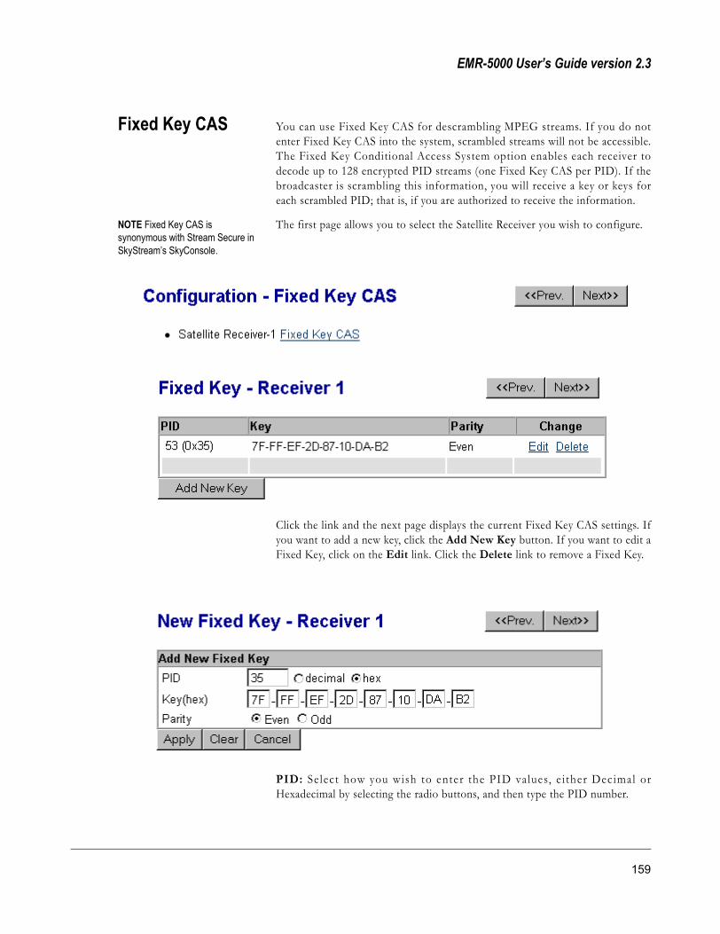
EMR-5000 User’s Guide version 2.3
Fixed Key CAS You can use Fixed Key CAS for descrambling MPEG streams. If you do notenter Fixed Key CAS into the system, scrambled streams will not be accessible.The Fixed Key Conditional Access System option enables each receiver todecode up to 128 encrypted PID streams (one Fixed Key CAS per PID). If thebroadcaster is scrambling this information, you will receive a key or keys foreach scrambled PID; that is, if you are authorized to receive the information.
NOTE Fixed Key CAS is synonymous with Stream Secure in SkyStream’s SkyConsole.
The first page allows you to select the Satellite Receiver you wish to configure.
Click the link and the next page displays the current Fixed Key CAS settings. Ifyou want to add a new key, click the Add New Key button. If you want to edit aFixed Key, click on the Edit link. Click the Delete link to remove a Fixed Key.
PID: Se lect how you wish to enter the PID values, e i ther Dec imal orHexadecimal by selecting the radio buttons, and then type the PID number.
159

SkyStream Networks
Key (Hex): Type eight hexadecimals in the following format XX-XX-XX-XX-XX-XX-XX-XX
Parity: Select parity to either odd or even using the radio buttons.
Click the Apply button to set the Fixed Key CAS. To remove the entry, click theReset button, and to stop the entry, click the Cancel button.
Click the Edit link to edit the Fixed Key CAS setting.
160 Web GUI Configuration

EMR-5000 User’s Guide version 2.3
TCP Acceleration TCP Acceleration optimizes the use of TCP over satellite. TCP Accelerationsupports both passive and active FTP, concurrent TCP connections, VSAT, andredundancy backup.
To configure the SkyStream EMR for TCP Acceleration, you must enterconnection information into the following tabbed panes:
� Network Settings
� Compression Settings
� User Defined Ports
NOTE These values are set per EMR and are not saved in a configuration file.
161

SkyStream Networks
Network Settings
Click the Network Settings tab and enter the following information:
Server Side Settings
• Primary Remote Server Address: Enter the IP address and port used by theTCP Acceleration primary server.
• Secondary Remote Server Address: If you want a backup server, enter theIP address and port for the TCP Acceleration secondary server.
• POP3 Server Address: If you want to use an e-mail program to send mail,enter the IP address and port of your Post Office Protocol 3 (POP3) mailserver.
NOTE For information on using TCP Acceleration with various browsers, mailprograms and FTP applications see Appendix B: TCP Acceleration—WorkingWith Applications.• SMTP Server Address: If you want to use an e-mail program to receive mail,
enter the IP address and port of your Simple Mail Transfer Protocol (SMTP)mail server.
162 Web GUI Configuration

EMR-5000 User’s Guide version 2.3
• NNTP Server Address: If you want to use a Network News TransportProtocol (NNTP), enter the IP address and port of your NNTP server.
Client Side Settings
• HTTP Listen Port: Enter the HyperText Transport Protocol (HTTP) portused by the TCP Acceleration Client (default is 9090).
• FTP Listen Port: Enter the File Transfer Protocol (FTP) port used by theTCP Acceleration Client (default is 9091).
• SSL Listen Port: Enter the Secure Sockets Layer (SSL) port used by the TCPAcceleration Client (default is 9092).
• POP3 Listen Port: Enter the POP3 port used by the TCP AccelerationClient.
• SMPT Listen Port: Enter the SMTP port used by the TCP AccelerationClient.
• NNTP Listen Port: Enter the NNTP port used by the TCP AccelerationClient.
163

SkyStream Networks
Compression Settings
Click the Compression Settings tab and enter the following information:
• Compression: Enter the IP address and port used by the TCP Accelerationprimary server.
• Compression Level: This display allows you to select the level ofcompression. The highest compression level is 9 and the lowest is 1.
• HTTP Compression: Select one of the radio buttons (Yes or No).
• FTP Compression: Select one of the radio buttons (Yes or No).
• Compressed File Extensions: *.txt, *.doc, *.html, *.htm and *.bmp aredefault extensions. However, you may delete them, if you wish, by clicking theapplicable Delete button. In addition, you may type new extensions into thetext box at the bottom of the list, and add them to the list by clicking the Addbutton. After making changes, click the Apply button.
NOTE Compression Settings also displays the Maximum number of TCPconnections allowed (1000).
164 Web GUI Configuration

EMR-5000 User’s Guide version 2.3
User Defined Ports
Click the User Defined Services tab and add or delete information, as required.
• Free-TCP Server Address: Enter the IP address used by the TCPAcceleration primary server and port numbers for the Server side and Clientside (client default is 5631). You may delete the entry lines by clicking theapplicable Delete button. In addition, you may type new lines into the textbox at the bottom of the list, and add them to the list by clicking the Addbutton. After making changes, click the Apply button.
PreferencesPreferences allows you to “Enable” or “Disable” Transparent Proxy. For HTTPonly, by enabl ing Transparent Proxy you do not have to enter proxyinformation to the client connected to the EMR.
165

SkyStream Networks
Turbo Internet/VPN SkyStream’s Turbo Internet solution employs an asymmetrical satellite networkthat provides a high-speed delivery system. Turbo Internet uses the EMR, in anend-to-end broadband content delivery system that includes an IP encapsulator,such as the SkyStream satellite Source Media Router (SMR). Most Internettraffic is asymmetrical in nature. There is much more data going toward theInternet terminal than away from it. The Turbo Internet takes advantage of thisfact and employs a high-capacity forward path and a lower-capacity return path,such as ISDN or modem. SkyStream’s solution also incorporates Virtual PrivateNetworking (VPN), which emulates point-to-point connectivity. For a secureVPN, data is encrypted using a protocol called the Point-to-Point TunnelingProtocol (PPTP), or IPSec.
NOTE Demand dialing is not supported when the LAN is the return channel.
To configure the SkyStream EMR for Turbo Internet/VPN, you must enterconnection information into the following tabs:
� PPTP
� IPSec
� Connection Method
� Demand Rules
� Advanced Options
166 Web GUI Configuration

EMR-5000 User’s Guide version 2.3
NOTE These values are set per EMR and are not saved in a configuration file.Click the Manual connect now button at the bottom of the main TurboInternet/VPN configuration properties page to immediately try to make aconnection or click Connect on demand to initiate connection throughDemand Rules. NOTE When PPTP is connected, IPSec is d isconnected. S imi lar ly, whenIPSec is connected, PPTP is disconnected.
Manual connectThe EMR will attempt to establish a PPTP or IPSec tunnel with the remoteserver as soon as you click Manual Connect (or if the EMR is loaded with aconfiguration file that was set for Manual Connect). If the connection attemptfails, or the remote server is disconnected, EMR will repeatedly try to connect tothe server. You should use this mode should be used if you want the tunnel toremain up continuously.
Connect on demandThe EMR will establish a connection with the PPTP server or IPSec gatewayonly when “interesting” packets arrive. These are packets which match one ofthe ACCEPT demand rules, as specified on the Configuration - Turbo Internetpage. If the connection is idle for the specified timeout, EMR will disconnectfrom the tunnel server. This feature may be used in conjunction with PPP orISDN demand dialing to maintain a tunnel connection only as long as there is aneed.
In the demand case, you can install a route to act as a proxy while the tunnel isdisconnected. For PPTP, this proxy is the default route. For IPSec you can installthis proxy as a network route to the remote subnet.
NOTE If both Turbo Internet and PPP/ISDN are configured for demandtunnels and demand dial, the idle timeouts are treated independently. If TurboInternet is configured for 90-second timeout, and the PPP is configured for a120 second timeout, the modem will remain connected for 210 seconds afterthe connection becomes idle. The tunnel will close after 90 seconds, and afteranother 120 seconds of inactivity the modem will hang-up. If you change theDemand Rules or timeout, you need to disconnect and reconnect PPP orTurbo Internet.
167

SkyStream Networks
Advanced ButtonClick the Advanced button to set logging options.
IPSec Logging Options• IPSec/IKE Interaction
• Messages
• Control
• Crypto
• Raw Bytes
PPTP Logging Options• General (Always enabled)
Select options and click View Log to check information.
168 Web GUI Configuration
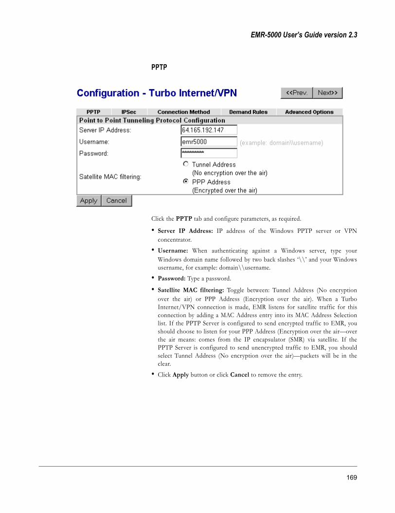
EMR-5000 User’s Guide version 2.3
PPTP
Click the PPTP tab and configure parameters, as required.
• Server IP Address: IP address of the Windows PPTP server or VPNconcentrator.
• Username: When authenticating against a Windows server, type yourWindows domain name followed by two back slashes ‘\\’ and your Windowsusername, for example: domain\\username.
• Password: Type a password.
• Satellite MAC filtering: Toggle between: Tunnel Address (No encryptionover the air) or PPP Address (Encryption over the air). When a TurboInternet/VPN connection is made, EMR listens for satellite traffic for thisconnection by adding a MAC Address entry into its MAC Address Selectionlist. If the PPTP Server is configured to send encrypted traffic to EMR, youshould choose to listen for your PPP Address (Encryption over the air—overthe air means: comes from the IP encapsulator (SMR) via satellite. If thePPTP Server is configured to send unencrypted traffic to EMR, you shouldselect Tunnel Address (No encryption over the air)—packets will be in theclear.
• Click Apply button or click Cancel to remove the entry.
169

SkyStream Networks
IPSec
Click the IPSec tab and configure parameters, as required, then click Applybutton or click Cancel to remove the entry.
NOTE IPSec requires configuration to be exact. This may require debugging;in which case, see Chapter 6, “Troubleshooting” for IPSec Debugging.
170 Web GUI Configuration

EMR-5000 User’s Guide version 2.3
IPSec Configuration• Remote Gateway IP Address: IP address of the remote gateway or VPN
concentrator.• IPSec mode: Select from “Tunnel Mode” or “Transport Mode”
NOTE Tunnel Mode applies ESP encryption and authentication to the entireoriginal IP packet (IP header and data), thus hiding the ultimate source anddestination addresses. This is the default selection, and it is the most secure.Transport Mode applies ESP encryption and authentication only to thetransport layer segment (data only) of the original IP packet. This modeprotects packet contents but not the ultimate source and destinationaddresses.
Tunnel mode settings• Remote Subnet (leave blank if not used): Remote subnet address
• Remote Subnet Mask (leave blank if not used): Remote subnet maskaddress
• Local Subnet (leave blank if not used): Local subnet address
• Local Subnet Mask (leave blank if not used): Local subnet mask address
IPSec is very selective about which IP traffic is actually encrypted/authenticatedand sent through the tunnels. For traffic to be sent though an IPSec tunnel itmust have specific source and destination IP addresses. The tunnel modesettings are used to configure these addresses.
• For IP packets sent from EMR to the remote gateway, the IP packet sourceaddress must match the Local Subnet and Local Subnet Mask settings. The IPpacket destination address must match the Remote Subnet and RemoteSubnet Mask settings.
• For IP packets sent from the remote gateway to EMR, the IP packet sourceaddress must match the Remote Subnet and Remote Subnet Mask settings.The IP packet destination address must match the Local Subnet and LocalSubnet Mask settings. Otherwise, the packet will not travel through the IPSectunnel.
The end of an IPSec tunnel can terminate at an entire subnet or at the single IPaddress of the IPSec gateway. This allows EMR to support four tunnel scenarios.These scenarios describe which traffic is sent through the IPSec tunnels:
• LAN-to-LAN: Traffic from local subnet (attached to EMR) to remote subnet(attached to remote gateway). Both the local subnet and remote subnet mustbe entered.
• LAN-to-Gateway: Traffic from local subnet (attached to EMR) to the remotegateway. Only the local subnet should be entered. The remote subnet shouldbe left blank.
Tunnel mode Enables AH or ESP to process the network layer protocol —the main advantage is that the IP header can be fully encrypted and authenticated. In addition, it uses the IP address of VPN initiator to hide the VPN client's IP address.
Transport mode Enables AH or ESP to process transport layer field and /or higher layers of the datagrams. Most of the time compulsory Tunnels (EMR is the terminating edge) can be configured in tunnel mode and Voluntary Tunnels (client PC is terminating edge) in transport mode.
171

SkyStream Networks
• Gateway-to-LAN: Traffic from EMR to the remote subnet (attached toremote gateway). Only the remote subnet should be entered. The local subnetshould be left blank.
• Gateway-to-Gateway: Traffic from EMR to the remote gateway. Leave boththe local subnet and the remote subnet blank.
NOTE To use EMR in a classic VPN configuration, LAN-to-LAN mode shouldbe used.
Internet Key Exchange (IKE)
• Encryption Algorithm: Select from the following list: DES (56-bit), and3DES (168-bit).
NOTE The EMR uses Triple-DES encryption as a default because it is themost secure.• Authentication Algorithm: Select from “HMAC-MD5 (128-bit)” or
“HMAC-SHA1 (160-bit).”
NOTE MD5 uses a 128-bit hash and is fastest. SHA1 uses a 160-bit hash andis more secure but requires more processing overhead.• Diffie-Hellman Group: Select from the following: Group 1 (768-bits),
Group 2 (1024-bits), and Group 3 (1536-bits).
NOTE The EMR uses Perfect Forward Secrecy (PFS) by default. PFS is acryptographic concept where each new key is unrelated to any previous key.In IPSec negotiations, Phase 2 keys are based on Phase 1 keys unlessPerfect Forward Secrecy is specified. Perfect Forward Secrecy uses Diffie-Hellman techniques to generate the keys. You must select one of thefollowing groups and make sure that PFS is enabled at both the EMR andVPN side:Group 1 (768-bits) Use PFS and Diffie-Hellman Group 1 to generate IPSecsession keys, where the prime and generator numbers are 768 bits. Thisoption requires the least processing overhead.Group 2 (1024-bits) Use PFS and Diffie-Hellman Group 2 to generate IPSecsession keys, where the prime and generator numbers are 1024 bits. Thisoption is more secure than Group 1 but requires more processing overhead.Group 5 (1536-bits) Use PFS and Diffie-Hellman Group 5 to generate IPSecsession keys, where the prime and generator numbers are 1536 bits. Thisoption is more secure than Group 2 but requires more processing overhead.
• Authentication Mode: Pre-shared key is the only choice in this release.
• Shared secret (PSK): Type prearranged phrase to use for authentication.
IPSec Security Associations (SA)• Use Authentication Header (AH): Select check box.
DES (Data Encryption Standard) A National Institute of Standards and Technology (NIST) secret key cryptography method that uses a 56-bit key. DES is based on an IBM algorithm, which uses the block cipher method that breaks the text into 64-bit blocks before encrypting them.
172 Web GUI Configuration

EMR-5000 User’s Guide version 2.3
NOTE Authentication Header (AH) and Encapsulating Security Protocol (ESP)may be used separately or in combination. If you choose to use themtogether, you may use separate authentication algorithms for each.
• Authentication Algorithm: Select from the following list: MD5 (128-bit) orSHA1 (160-bit).
NOTE The EMR default is MD5/HMAC-128; that is, ESP using HMAC (HashedMessage Authentication Coding) with the MD5 hash function, which uses a128-bit key. SHA1/HMAC-160 is ESP using HMAC with the SHA-1 hashfunction, which uses a 160-bit key. This selection is more secure but requiresmore processing overhead.• Use Encapsulating Security Payload (ESP): Select check box
• Encryption Algorithm: Select from the following list: DES (56-bit), and3DES (168-bit).
• Authentication Algorithm: Select “MD5 (128-bit)” or “SHA1 (160-bit).”
• Replaces keys every: Keys replaced in increments of seconds and kilobytesof data, whichever comes first.
PSK (Pre-Shared Key) A prearranged passphrase that is shared by two sides. PSK is an authentication method for IPSec.
AH (Authentication Header) A protocol used by IPSec. AH provides data integrity, origin authentication, and replay resistance.
ESP (Encapsulating Security Payload) A protocol used by IPSec, EPS provides data confidentiality, integrity, origin authentication, replay resistance, and limited traffic flow confidentiality.
173

SkyStream Networks
Connection MethodClick the Connection Method tab and configure parameters, as required.
• Connect using: Select from the following list: No tunneling protocol (NATonly), Point-To-Point Tunneling Protocol, and IPSec.
No tunneling protocol (NAT only) connection
NOTE If configured as No Tunneling Protocol with NAT enabled, and a MACfiltering entry is added, no connection is made to any tunneling server. Thismode should be used when the client machine itself is going to be a VPNclient; for example, a Windows Client PC connected to an EMR thatestablishes a PPTP connection to a remote PPTP server. Note that, only onePPTP client can be used per subnet in this case. IPSec clients usually cannotbe used, because NAT rewrites packet headers, which causes IPSec packetintegrity checking to fail.
IPSec connection
174 Web GUI Configuration

EMR-5000 User’s Guide version 2.3
• Initiate connection: Click “Manual connect now” or “Connect on demand.”Connect on demand—the Turbo Internet/VPN connection will be tried assoon as the PPP or ISDN link is established. Demand dialing should normallybe configured to take full advantage of this mode. Manual connect now—theTurbo Internet/VPN connection will be tried when the user clicks theConnect button on the main Configuration - Turbo Internet/VPN page.Click Apply button or click Cancel to remove the entry.
Example IPSec or PPTP:
If the destination IP address is 10.1.1.2 and MAC Prefix is set to 0000, the EMRwould listen for incoming packets with a MAC address of 00:00:0a:01:01:02.Check your IP Encapsulator (SMR) settings to determine what this value shouldbe.
Example No Tunneling Protocol:
Use the following steps to enable NAT if you have a single modem:
1 Click Advanced Options and apply NAT by selecting an Ethernet. ClickApply.
2 Click Connection Method and Connect using: No Tunneling Protocol.Click Apply.
3 Go to the main Turbo Internet/VPN page and click Enable NAT button.
175

SkyStream Networks
Demand RulesThe demand rules for Turbo Internet/VPN are separate from PPP and ISDN toallow you to customize different demand rules for tunneled and non-tunneledtraffic.
Click the Demand Rules tab to connect, view, edit, and delete rules. You cancreate a new rule by clicking the Add New Rule button at the bottom of the
176 Web GUI Configuration
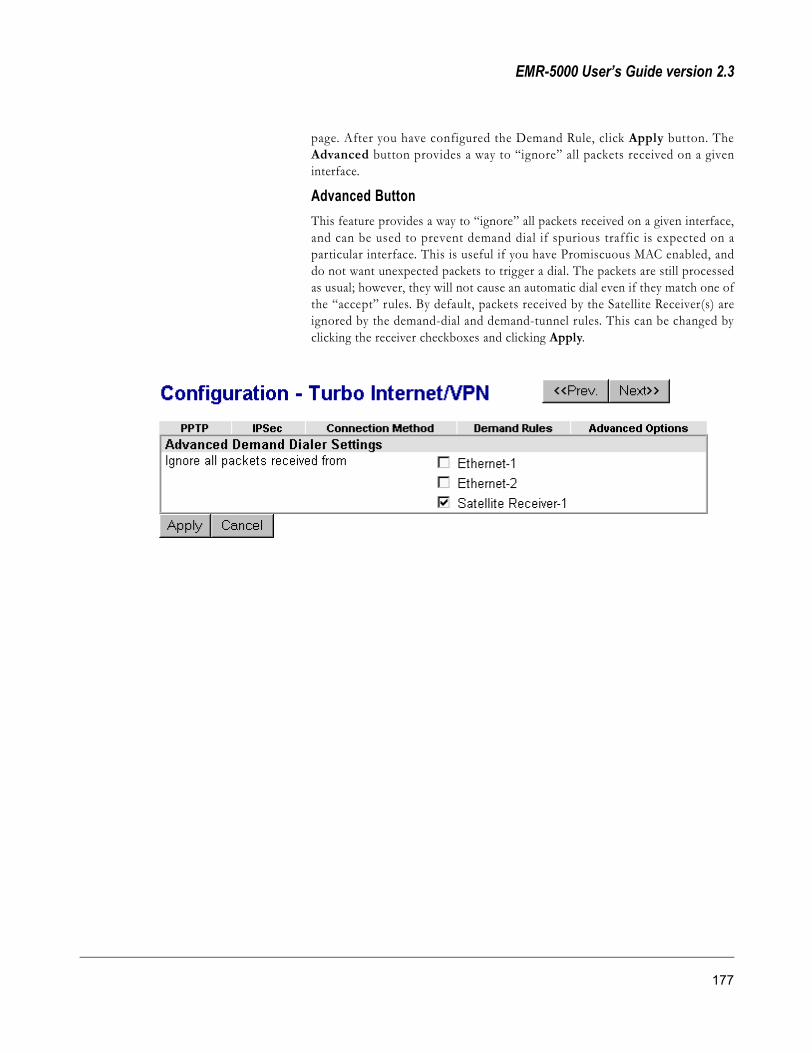
EMR-5000 User’s Guide version 2.3
page. After you have configured the Demand Rule, click Apply button. TheAdvanced button provides a way to “ignore” all packets received on a giveninterface.
Advanced ButtonThis feature provides a way to “ignore” all packets received on a given interface,and can be used to prevent demand dial if spurious traffic is expected on aparticular interface. This is useful if you have Promiscuous MAC enabled, anddo not want unexpected packets to trigger a dial. The packets are still processedas usual; however, they will not cause an automatic dial even if they match one ofthe “accept” rules. By default, packets received by the Satellite Receiver(s) areignored by the demand-dial and demand-tunnel rules. This can be changed byclicking the receiver checkboxes and clicking Apply.
177

SkyStream Networks
Click Edit or Add New Rule and enter the following information:
• Action: Select from list “accept,” or “ignore.” See Configuration PPP, Demanddialer rules.
• Protocol: Select from the following list: TCP, UDP, ICMP, IGMP, EGP, GRE,IPv6-in-IPv4, ESP, AH, or any protocol.
NOTE Only TCP and UDP may use port numbers.• Source IP Address: The source IP address of packets that matches this rule.
• Netmask: The netmask associated with the source IP address that matchesthis rule.
• Destination IP Address: The destination IP address that matches this rule.
• Netmask: The destination netmask that matches this rule.
• Source Port (0 for any): The source port number for packets that matchesthis rule. Type zero ‘0’ if the port number doesn’t matter.
• Destination Port (0 for any): The destination port number for packets thatmatches this rule. Type zero ‘0’ if the port number doesn’t matter.
If you click the Restore factory default rules button, you will delete all thecurrent rules and replace them with a factory default set of rules. These rulesshould be sufficient for most users, and they can be modified as necessary.
IPv6-in-IPv4 A next-generation Internet Protocol, known first as IPng and then as IPv6, has been under development by the Internet Engineering Task Force (IETF) for several years to replace the current Internet Protocol known as IPv4.
178 Web GUI Configuration
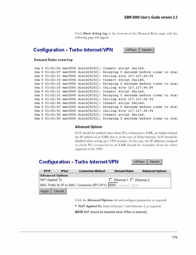
EMR-5000 User’s Guide version 2.3
Click Show debug log at the bottom of the Demand Rules page and thefollowing page will appear:
Advanced OptionsNAT should be enabled when client PCs, connected to EMR, are hidden behindthe IP address of an EMR; that is, in the case of Turbo Internet. NAT should bedisabled when setting up a VPN scenario. In this case, the IP addresses assignedto cl ient PCs connected to an EMR should be routeable from the othersegments of the VPN.
Click the Advanced Options tab and configure parameters, as required.
• NAT Applied To: Select Ethernet 1 and Ethernet 2, as required.
NOTE NAT should be disabled when IPSec is selected.
179

SkyStream Networks
• MAC Prefix for IP to MAC Conversion (IPCOPY): Default is “0000,” inhexadecimal.
NOTE An IP address contains 32-bits, and a MAC address 48-bits. MACPrefix for IP MAC Conversion puts the hexadecimal entered (16-bits) infront of the IP address.
180 Web GUI Configuration

EMR-5000 User’s Guide version 2.3
Sync The Sync-In port option can receive streams of synchronous data from an SMRand forward an MPEG-2 Transport Stream through a Sync card to a SyncReceiver.
To configure the SkyStream EMR for Sync, enter the following information:
Sync Configuration• PID: Enter the PID value and select Decimal or Hexadecimal by selecting the
radio buttons, and then type the PID number.
• Serial bit shift: Select the radio button first MSB or first LSB depending onthe respective SMR setting for Sync. See SMR User’s Guide, Chapter 5,“Configure Sync In Hardware Driver.”
Clock SettingYou can specify the speed within the range of 1 to 8 Mbits/s in bps.
NOTE Depending on the sync card installed there may be an external clock toset.
General Information• Media Type: Displays the hardware interface.
• Protocol: Displays the data stream format used.
• Interface: Displays the status of the connection.
After configuration, click Apply button or click Cancel to remove the entry.
MSB (Most Significant Bit) The first bit in a bit field.
LSB (Least Significant Bit) The lowest-order bit.
181

SkyStream Networks
Date and Time The Date and Time option allows you to configure the clock either from aninternal source or NTP Server.
To configure the SkyStream EMR for Date and Time, enter the followinginformation:
Date and Time Configuration• Current Local Time: Nothing to enter—gives the time from the EMR
internal clock or NTP Server.
• UTC Time: Nothing to enter—gives the Coordinated Universal Time basedon the internal clock setting and the local time zone.
• Set Local Time: Select the month and type in the day and year. Type in hoursand minutes; and select AM or PM.
• Time Zone: Select one of the POSIX standard time zones.
• NTP Time Server IP Address (optional): If you want to receive your timefrom an external source, type the IP address of the NTP server.
• Synchronize clock to NTP server: Select the applicable radio button. Thechoices are “Never” or “Every” (type in how often you want to set the time)“minutes.”
After configuration, click Apply button or click Cancel to remove the entry.
NTP (Network Time Protocol) A protocol used to synchronize the clocks of two computers on the network in a master/slave fashion.
182 Web GUI Configuration

EMR-5000 User’s Guide version 2.3
E-Mail Notification E-Mail notifies up to three recipients information about the status of the EMR.The contents of this information can be one or all of the following: PPPConnection Information, Satellite Receiver Lock/Unlock Status, FrequencyDetails, Symbol Rate, Viterbi Rate, Signal/Noise Ratio (Eb/N0), Viterbi Bit-Error Rate, QPSK Bit-Error Rate, and Active PIDs. You can also select toautomatically send e-mail or send e-mail now.
183
SkyStream Networks
To configure the SkyStream EMR for e-mail, enter the following information:
E-Mail Notification Configuration• SMTP Relay Server IP Address: Type the IP address for the standard
Internet e-mail protocol.• Sender e-mail address: Type the sender's e-mail address. The default is
“emr5000@localhost.”
• Recipient E-mail Address (Up to three): Type the e-mail addresses that youwant to receive EMR status information.
• Subject Line: Type the subject of the e-mail. The default is “EMR E-mailNotification.”
• Contents of E-mail Notification: Select the check boxes for contents of e-mail notification. You can select from the following check boxes: PPPConnection Information, Satellite Receiver Lock/Unlock Status, FrequencyDetails, Symbol Rate, Viterbi Rate, Signal/Noise Ratio (Eb/N0), Viterbi Bit-Error Rate, QPSK Bit-Error Rate, and Active PIDs.
• Automatically Send E-mail: Select the applicable radio button. The choicesare “Never” or “When PPP/ISDN Link is established.”
• Number of retries, in case first attempt fails: Type a value for the numberof times the EMR should try to send the e-mail notification.
• Delay between retries (seconds): Type a value for the number of secondsbetween retries.
After configuration, click Apply button or click Cancel to remove the entry. Ifyou want to send the e-mail immediately then click Send e-mail now button.
184 Web GUI Configuration
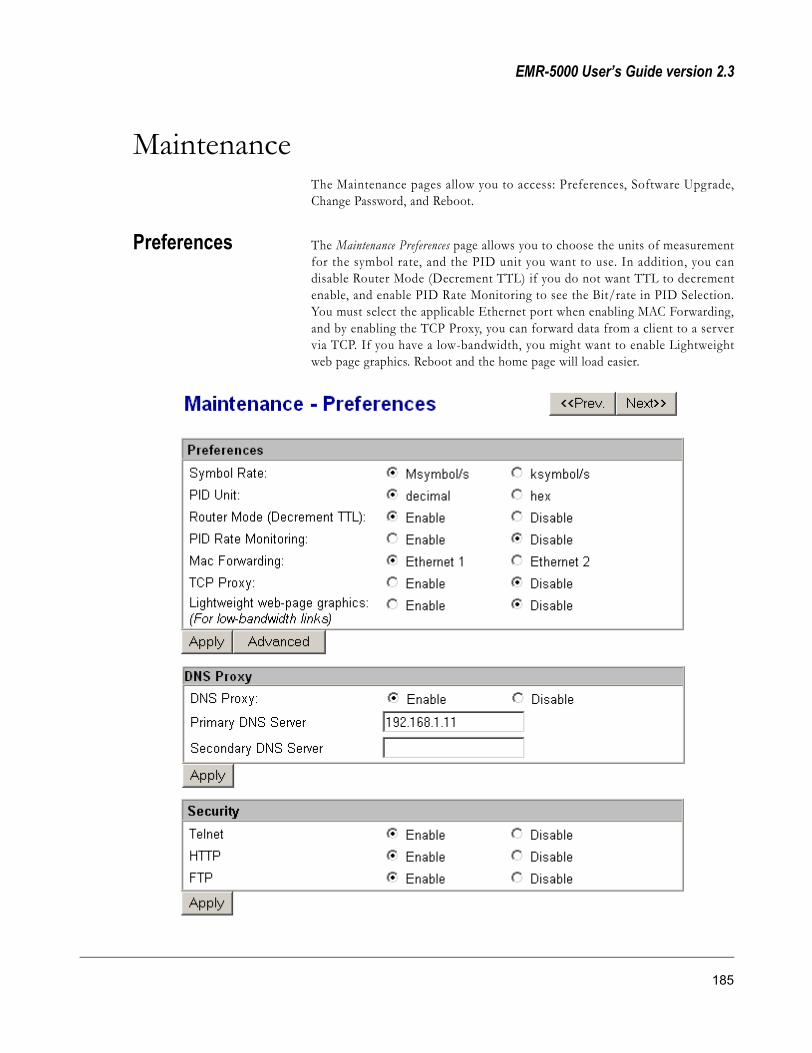
EMR-5000 User’s Guide version 2.3
MaintenanceThe Maintenance pages allow you to access: Preferences, Software Upgrade,Change Password, and Reboot.
Preferences The Maintenance Preferences page allows you to choose the units of measurementfor the symbol rate, and the PID unit you want to use. In addition, you candisable Router Mode (Decrement TTL) if you do not want TTL to decrementenable, and enable PID Rate Monitoring to see the Bit/rate in PID Selection.You must select the applicable Ethernet port when enabling MAC Forwarding,and by enabling the TCP Proxy, you can forward data from a client to a servervia TCP. If you have a low-bandwidth, you might want to enable Lightweightweb page graphics. Reboot and the home page will load easier.
185

SkyStream Networks
DNS ProxyDNS Proxy allows you to enable the EMR as a DNS proxy server, therebyupdating configuration files based on DNS information obtained once the PPPconnection is established. It is necessary to enter an IP address for the primaryDNS. Any address is acceptable initially; after which, the ISP will automaticallyupdate the DNS entries. The secondary DNS server is a backup. If you disableDNS Proxy then the DHCP configurat ion is updated with DNS ser verinformation obtained from the ISP.
SecurityThe Security section allows you to enable or disable Telnet, HyperTerminal, andthe FTP server on port 21.
SMMPSkyStream Multicast Management Protocol allows you to specify the control anddata addresses for your SMMP multicast protocol. All units must have the samecontrol and data multicast addresses to communicate. These values shouldmirror E-Manager’s Advanced Preference. You must unlock the radio buttons toedit the values.
NOTE When making changes, it is necessary to make the same changes onthe client E-Manager side.
PID
� Control PID: MPEG PID used for SMMP through IP.
� Data PID: MPEG PID used for SMMP through IP.
Port
� Control Port: SMMP control endpoint port number of EMR node in group.
DNS (Domain Name System) Name resolution software that lets users locate computers on a UNIX network or the Internet (TCP/IP network) by domain name. The DNS server maintains a database of domain names (host names) and their corresponding IP addresses.
186 Web GUI Configuration
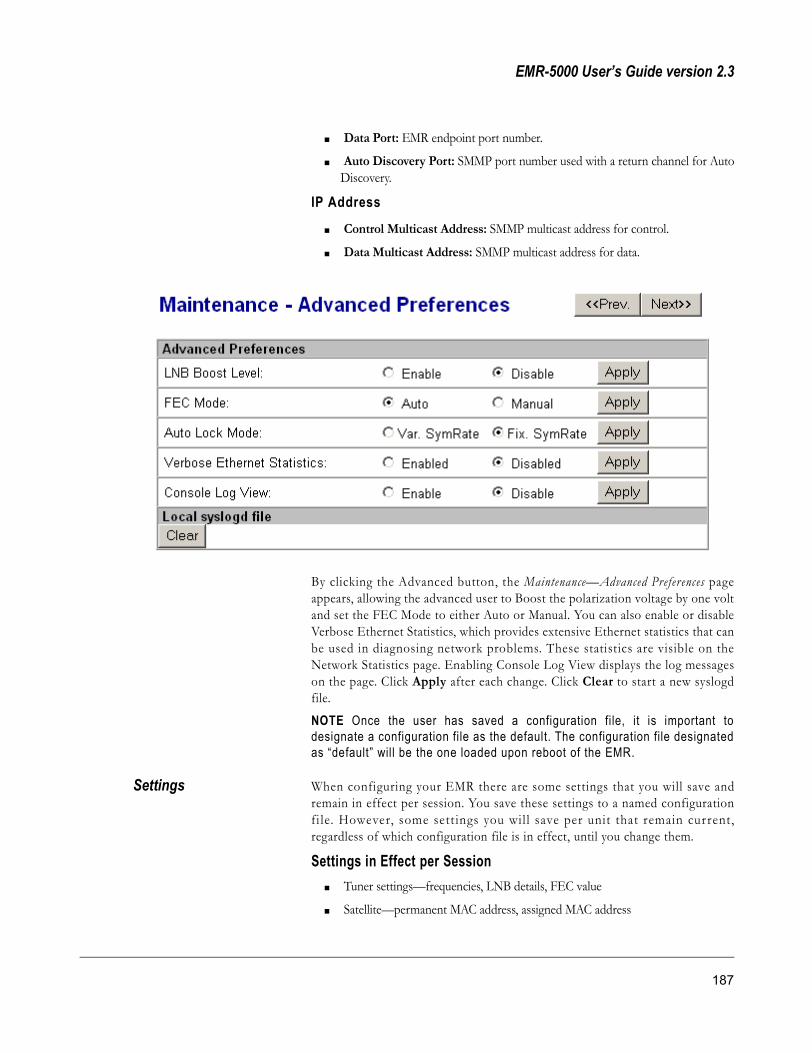
EMR-5000 User’s Guide version 2.3
� Data Port: EMR endpoint port number.
� Auto Discovery Port: SMMP port number used with a return channel for AutoDiscovery.
IP Address
� Control Multicast Address: SMMP multicast address for control.
� Data Multicast Address: SMMP multicast address for data.
By clicking the Advanced button, the Maintenance—Advanced Preferences pageappears, allowing the advanced user to Boost the polarization voltage by one voltand set the FEC Mode to either Auto or Manual. You can also enable or disableVerbose Ethernet Statistics, which provides extensive Ethernet statistics that canbe used in diagnosing network problems. These statistics are visible on theNetwork Statistics page. Enabling Console Log View displays the log messageson the page. Click Apply after each change. Click Clear to start a new syslogdfile.
NOTE Once the user has saved a configuration file, it is important todesignate a configuration file as the default. The configuration file designatedas “default” will be the one loaded upon reboot of the EMR.
Settings When configuring your EMR there are some settings that you will save andremain in effect per session. You save these settings to a named configurationfi le. However, some sett ings you wil l save per unit that remain current,regardless of which configuration file is in effect, until you change them.
Settings in Effect per Session� Tuner settings—frequencies, LNB details, FEC value
� Satellite—permanent MAC address, assigned MAC address
187

SkyStream Networks
� FKCAS info—PIDs, keys and parities
� PID info—list of active PIDs
� MACs info—MAC filtering information, promiscuous mode
� Enable/Disable
� IGMP settings
� SkyCastRules—default/normal rules and status (active/inactive)
� SkyNAT rules—rules and status (active/inactive)
� SkyNPT rules—rules and status (active/inactive)
� SYNC—configuration parameters
� ISDN—configuration parameters
� SMMP—lock status of all parameters
Settings in Effect per Unit� EMR usernames and passwords
� SNMP configuration
� DHCP server configuration
� SSH and SSL keys
� Diagnostics output (if the user has run diagnostics)
� Upgrade key
� RIP enable/disable
� Telnet, http, and enable/disable
� Eth1/Eth2 setup
� DHCP enable/disable
� IP addresses, netmask, broadcast address
� Tuner setup—IP address, netmask, broadcast address
� Static routes
� Remote syslog status (enable/disable)
� Log level settings (info/warn/critical)
� Log batching interval
� Preferences
NOTE In addition, all items under Maintenance—Preferences except SMMPsettings and configuration details for the following: PPP, Turbo Internet /VPN, TCP Acceleration setup including transparent proxy and enable/disable.
188 Web GUI Configuration

EMR-5000 User’s Guide version 2.3
Configuration File You can store and recall many different configurations from this page.
After you configure and set the SkyStream EMR, go to this page and type aname for this current session into the Save current config as box. Enter adescription for this configuration, select the Default check box, if required, thenclick the Save button.
NOTE Values for advanced options in TCP Acceleration, Turbo Internet, PPP, and ISDN apply to all configuration files per EMR and cannot be saved in a configuration file.
IMPORTANT The Restore Factory Default button is handy when you wantto start a fresh. However, this clears all information, including the currentupgrade key. This means that the EMR will go back to Basic Mode. You mustreenter the upgrade key if you have one for Enhanced Mode.
To delete a session, click the Delete link next to the session name that you wantto remove. To load a specific session, click the Load link next to the sessionname that you want to load into the system. The (Loaded) notation appearsnext to the configuration session that was last loaded.
The last column on the page allows you to choose your default configuration.However, there is a “Default” that is not listed as a file that the EMR goes to ifno sessions are stored.
The EMR configuration does not persist until you save it. If you do not save andpower down the unit, your change will be lost.
189
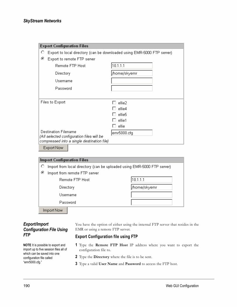
SkyStream Networks
Export/Import Configuration File Using FTP
You have the option of either using the internal FTP server that resides in theEMR or using a remote FTP server.
Export Configuration file using FTPNOTE It is possible to export and import up to five session files all of which can be saved into one configuration file called “emr5000.cfg.”
1 Type the Remote FTP Host IP address where you want to export theconfiguration file to.
2 Type the Directory where the file is to be sent.
3 Type a valid User Name and Password to access the FTP host.
190 Web GUI Configuration

EMR-5000 User’s Guide version 2.3
4 Type remote destination filename (*.cfg).
5 Select file to export from the check boxes available.
6 Click Export Now.
Import Configuration file using FTP1 Type the Remote FTP Host IP address where you want to import the
configuration file from.
2 Type the Directory where the file is located.
3 Type a valid User Name and Password to access the FTP host.
4 Click Import Now.
Using internal FTP to copy cfg file to another EMR
By using a laptop or other workstation connected to the network, you can FTPto the EMR through the Command Prompt. You can also copy to a floppy andtransfer the file that way.
1 Click the Windows Start button.
2 Click Run.
3 In the Open box, type: cmd
4 Click OK.
5 If required, at the command prompt change the drive and directory where youwant to save the configuration file. This is because the ftp “get” commandwill be saved to the local directory. At the prompt type: ftp xxx.xxx.xxx.xxx(“ftp” and the “IP Address” of the EMR you are connecting to)
6 Type at User <xxx.xxx.xxx.xxx:<none>>: emradmin or emruser and press Enter.
7 Type at Password: <your password>
8 Type at ftp> lsThis will give you a list of contents. You should see the file emr5000.cfg.
9 Type at ftp> get emr5000.cfg and press Enter.This will put a copy of the file into the local directory.
10 Type at ftp> bye. This will log you out.
11 Take your laptop or floppy and access the network that contains the EMR towhich you want to copy the configuration file.
12 Follow steps 1 to 7.
13 Type at ftp> put emr5000.cfg and press Enter.This will put a copy of the file into the EMR’s home directory.
191

SkyStream Networks
Software Upgrade Occasionally, SkyStream Networks will have available new software to upgradethe SkyStream EMR. The software upgrade works as fol lows: Place theSkyStream-supplied image file on an FTP server accessible to the EMR then youcan configure the EMR to go out and download the image file.
The following steps walk you through downloading and upgrading this software:
192 Web GUI Configuration

EMR-5000 User’s Guide version 2.3
How to download a software upgrade 1 Type the Remote FTP Host IP address where the software upgrade is
located.
2 Type the Directory where the image file is located.
3 Type a valid User Name and Password to access the FTP host.
4 Click the Go button. A new window will appear allowing you to select theversion of software you wish to replace.
The amount of time it takes to complete the download process is determined bynetwork traffic. The system will automatically bring up an information boxshowing the current versions of the software currently installed on the systemincluding the new version.
5 Reboot the EMR to begin using the new software upgrade.
NOTE If an upgrade error or problem with the new download occurs, the EMRis able to automatically fall back to the last successful working version.
Boot SelectionIf boot selection is set to “Auto” mode, the boot loader will load the kernel thatis most up-to-date. If set to “Manual” mode, the user must select a kernel that iscurrently available. This will be loaded the next time you boot the EMR. Theonboard flash has enough memory for two kernels: A Factory version on theflash, which is the software load shipped with the unit, and two user versions.The factory version cannot be deleted.
Choose a software kernel from the list box and click Apply to set the changes.
Feature UpgradeThe Feature Upgrade is used for applying addit ional pay features to theSkyStream EMR. To activate the Feature Upgrades, SkyStream will give you anupgrade key with your purchase. The upgrade key is entered into the Key field;all you have to do is click the Apply button to enable the additional features.NOTE When upgrading your EMR to enhance its capabilities, you will receivean Upgrade Key string. The Basic software package provides support for upto 28 M s ym b o l s , 32 P ID s , a n d 16 M A C A dd re s s es p e r r e ce i ve r. Th eEnhanced sof tware package provides suppor t for up to 45 Msymbols, 64PIDs, and 32 MAC Addresses per receiver.
TCP AccelerationDuring a software upgrade, it is important to disable TCP Acceleration. Aftercompleting the upgrade, select the Enable radio button and click the Applybutton.
193

SkyStream Networks
Change Password Depending on your password and security privileges, either emradmin oremruser, you can change the password.
After you have logged on for the first time, as outlined in Chapter 3, “SystemLogon,” a good practice is to change the password. However, make sure that youkeep a copy of the password in a safe place. If you forget or lose your password,see Chapter 6, “Troubleshooting—Password Recovery.”
After typing in the old password and entering the new password twice, click theChange button.
194 Web GUI Configuration

EMR-5000 User’s Guide version 2.3
System Reboot Occasionally, you will need to restart or reboot the SkyStream EMR aftersoftware upgrades or after changing the network settings.
To reboot the system, click the Reboot Now button. The EMR will reboot andstart back up with the new configuration changes. Check the LED indicatorlights on the front panel to see whether the EMR is functioning properly.
195

SkyStream Networks
DiagnosticsThe Diagnostics pages allow you to run and view System Diagnostics and LogFile Content, as well as network utilities such as Ping and Netstat.
Ping The Ping utility is used to test communications and view packet loss throughnetworks. Using the Ping uti l i ty with the SkyStream EMR, you can testconnectivity to a remote system by sending ICMP Ping packets and waiting for aresponse.
On the Network Utility Ping page, you are able to configure the ping functionsby filling in the following fields:
• Enter option(s) for ping: allows you to configure specific options to add tothe ping utility. (optional)
• IP Address: Where you want the ping to test connectivity.
• Packet Size: Enter the size of the packet you wish to transmit.
• Number of packets to send: Enter the number of packets the system willsend.
Once all the settings are ready, click the Apply button to run the ping utility.Wait a few seconds and a report will display on the success of the ping.
196 Web GUI Configuration
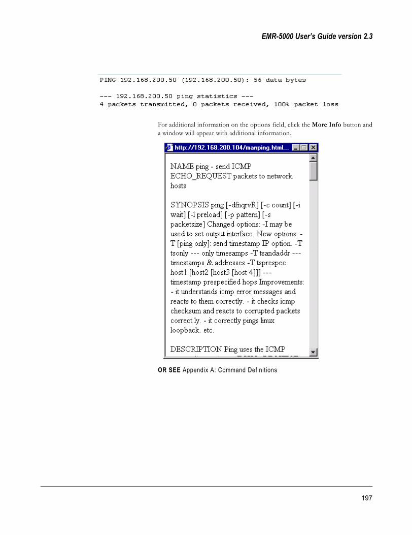
EMR-5000 User’s Guide version 2.3
For additional information on the options field, click the More Info button anda window will appear with additional information.
OR SEE Appendix A: Command Definitions
197

SkyStream Networks
Netstat The Netstat uti l i ty is used to display informat ion the Linux networkingsubsystem. It is capable of showing information on the network connections,routing tables, interface statistics, netlink messages, and multicast memberships,depending on the options you enter.
To configure the Netstat utility, enter the Netstat options. To run the utility,click the Apply button.
For more information on the Netstat options, click the More Info button and awindow will appear with additional information.
OR SEE Appendix A: Command Definitions
198 Web GUI Configuration

EMR-5000 User’s Guide version 2.3
System Check The System Check page checks the integrity of the EMR and generates a LogFile that you can send to SkyStream Networks for assistance to evaluate and helpsolve problems that might occur. The current Log File is saved and will benamed SkyDiag.txt. When you click the Run Tests button, the diagnosticprogram runs and places the new diagnostics information in the SkyDiag.txt file.
The following steps walk you through uploading the system check to another PCor to SkyStream for further assistance.
1 Click the Run Tests button.
2 Click the View button to see the results of the test.
199

SkyStream Networks
3 Enter the Remote FTP Host IP address
4 Enter the Path (directory) where the file should be saved.
5 Enter the Username and Password for the FTP Host or PC workstationwhere you are saving the file.
6 To upload the SkyDiag.txt file, click the Upload button.
The Upload Log File button accesses the current SkyDiag.txt and displays anFTP transfer window. Select the directory and enter the appropriate user nameand password to transfer the file to this directory for later review. This will helpwith troubleshooting any problems that may arise.
200 Web GUI Configuration
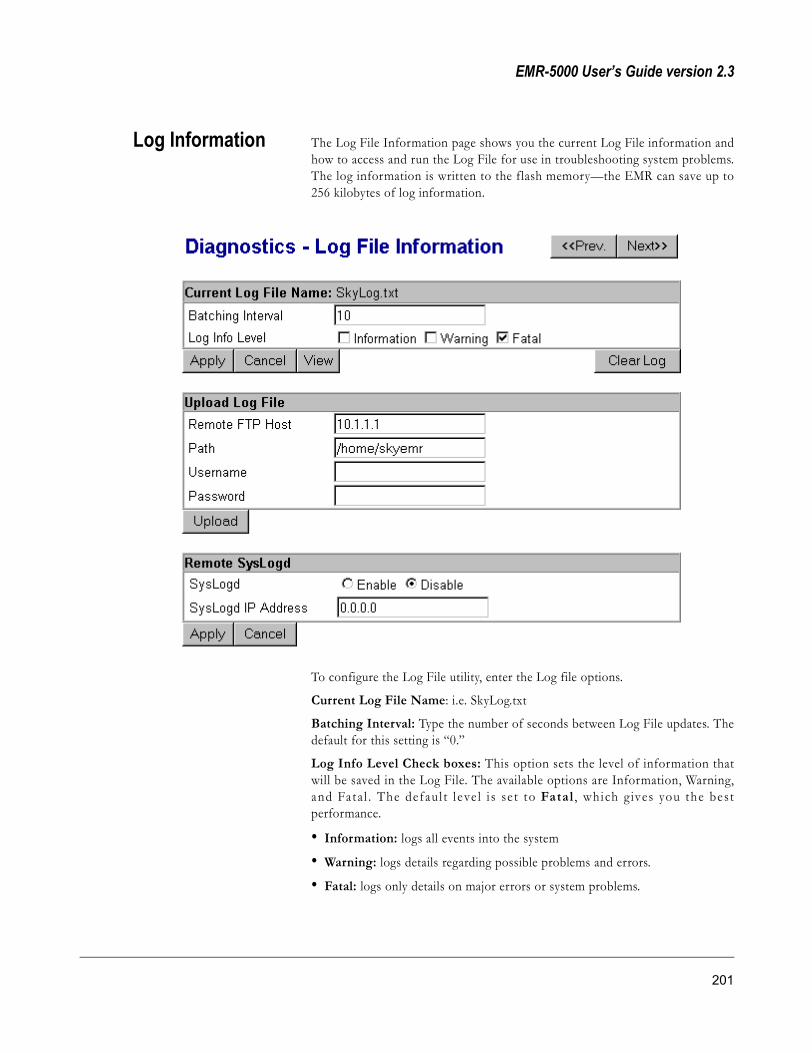
EMR-5000 User’s Guide version 2.3
Log Information The Log File Information page shows you the current Log File information andhow to access and run the Log File for use in troubleshooting system problems.The log information is written to the flash memory—the EMR can save up to256 kilobytes of log information.
To configure the Log File utility, enter the Log file options.
Current Log File Name: i.e. SkyLog.txt
Batching Interval: Type the number of seconds between Log File updates. Thedefault for this setting is “0.”
Log Info Level Check boxes: This option sets the level of information thatwill be saved in the Log File. The available options are Information, Warning,and Fata l . The defaul t l eve l i s se t to Fatal , which g ives you the bestperformance.
• Information: logs all events into the system
• Warning: logs details regarding possible problems and errors.
• Fatal: logs only details on major errors or system problems.
201

SkyStream Networks
• Click the Apply button to set the new configuration.
To reset the Log File configuration page, click the Cancel button. Click theView button to see the current Log File in a new page, or click Clear Log toremove log entries.
Remote FTP Host1 Type the Remote FTP Host IP address
2 Type the Path (directory) where the file should be saved.
3 Type the Username, and Password for the FTP Host or PC workstationwhere you are saving the file.
4 Click the Upload button to load the settings.
Remote SysLogdYou can save the Log File of a remote system by selecting the Enable radiobutton and typing in the remote IP address at SysLogd IP Access.
To view the Log File at any time, click the View button. A new page will appearwith the log file information.
NOTE If the setup is such that a large number of events are routinelygenerated, SkyStream recommends that the Log File be changed to Warningor Informational and that the Batching file be changed to a high enough valueso that the system is not slowed by constant updates to the Log File.
The default setting for the Log Info Level is chosen and designed to allow theEMR to operate a maximum efficiency. By just logging the fatal errors, fewerresources are being allocated to logging extra information to the flash memory.The flash memory allocated for the log file information has a maximum size of256K divided into two equal blocks of 128K each. When the memory on bothblocks is filled, the system erases the first block and begins writing again. Thiswill cause the system to remove the oldest log entries.
202 Web GUI Configuration
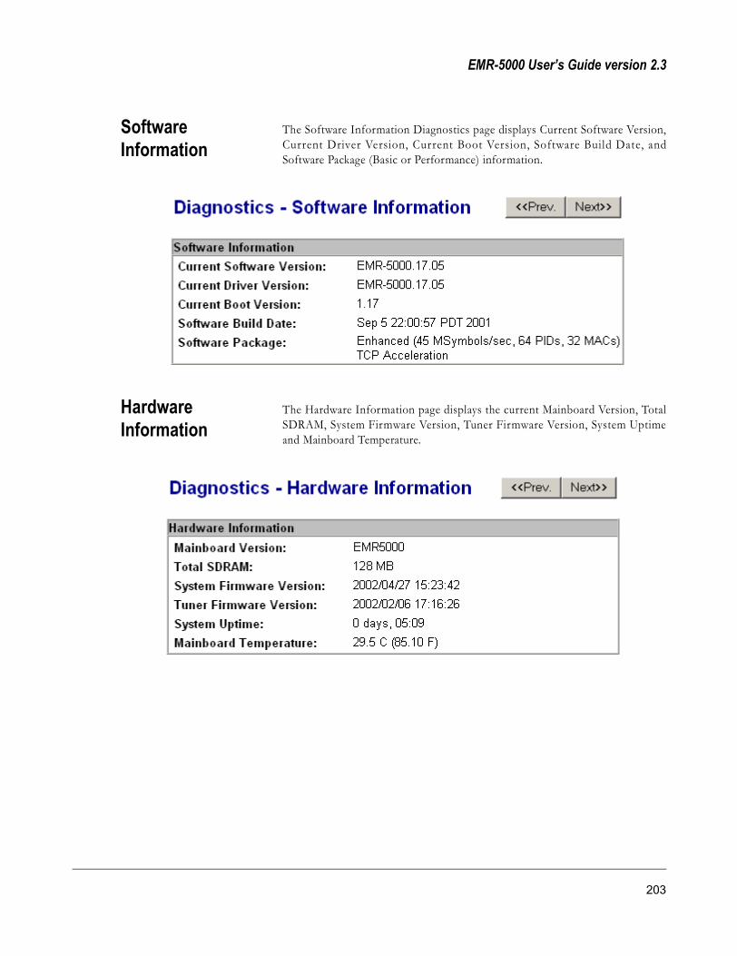
EMR-5000 User’s Guide version 2.3
Software Information
The Software Information Diagnostics page displays Current Software Version,Current Driver Version, Current Boot Version, Software Build Date, andSoftware Package (Basic or Performance) information.
Hardware Information
The Hardware Information page displays the current Mainboard Version, TotalSDRAM, System Firmware Version, Tuner Firmware Version, System Uptimeand Mainboard Temperature.
203

SkyStream Networks
204 Web GUI Configuration

EMR-5000 User’s Guide version 2.3
Chapter 6: Troubleshooting
205

SkyStream Networks
TroubleshootingThis chapter provides detailed information and procedures for isolating receivermalfunctions in a logical manner.
LED Display Troubleshooting the SkyStream EMR is accomplished easily and quickly byviewing the LED status lights on the front of the EMR. The current status ofthe EMR is found by reading the LED display. The table below describes thefunction of each indicator.
LED Display Properties Table
LEDs DescriptionLink Data
TS3TS2TS1
On/Off On/Off Transport Stream indicator LEDs. If the Link LED is on, there is a lock. If the Data LED is on, data is being received. The EMR is able to handle up to 3 transport streams (currently supports 2 streams).
Active ConfigEXP2EXP1
On/Off On/Off Expansion slot indicator LEDs. This feature is to be used with a future upgrade option.
Link/Active 100TX
LAN2LAN1
On/Off On/Off Network Connection indicator LEDs.If the Link/Active indicator is on, the corresponding Ethernet interface is connected and has link with the remote side. This indicator flashes when there is network traffic. The 100TX indicator will be on if the link connection is at 100 Mbps, and will stay off if the rate is at 10 Mbps.
Power On/Off The power LED indicates that the system is plugged in and turned on.Minor Alarm
On/Off The Minor Alarm indicator shows if the EMR has found a non-fatal error.(not available)
Major Error
On/Off The Major Alarm indicator shows if the EMR has encountered a major or fatal error. During loading the kernel will be turned on, and after a successful load, it will turn off.
206 Troubleshooting
EMR-5000 User’s Guide version 2.3
Error and Event Logging
The EMR has error/event logging capabil ities. The Log File can then beaccessed and printed out in order to troubleshoot system problems and/or sendthe Log File to SkyStream Networks for further assistance. Contact SkyStreamNetworks Customer Service with any questions or concerns.
Errors and events are reported and logged using the following mechanisms:
• Through SNMP, as traps, the EMR will support up to four trap destination IPaddresses. The responsibility of the SNMP manager is to receive the traps andsave them in the Log File.
• Using a standard Unix Syslog system, the EMR is configured to send logentries to a standard syslog daemon.
• Errors and events are logged and saved to the Log File.
NOTE Refer to the Log Information section in the Diagnostics chapter formore information on how to access this function.The following types of errors are logged to the Log File in order to aid introubleshooting:
• The satellite receiver subsystem lost its signal lock
• A new route was learned
• A new data PID has been detected
These events can be separated into the following parts:
• A timestamp of when the event occurred
• The subsystem generating the event
• Level of severity for the event
• Description of the event
• ID number for the event
207

SkyStream Networks
IPSec Debugging IPSec negotiation occurs in two phases: Internet Key Exchange (IKE) is used tocreate an Security Association (SA), followed by an IPSec Security Association(SA). Both phases must succeed before any data can traverse the connection.Due to the complexity of configuring IPSec, it may be necessary to debugparameters. To access the IPSec debug log, from the Configuration-TurboInternet/VPN page, click the Advanced button, select logging preferences, andclick View Log; the bottom of the log will give debugging information.
IPSec Debug Log messages:1 “initiating Main Mode”
If the connection is stuck here, it is likely that, either the packets cannot get tothe remote gateway, or the remote gateway IKE (Phase 1) parameters do notmatch those on the EMR.
2 “informational payload, type NO_PROPOSAL_CHOSEN”This message means that the IKE or IPSec parameters are not matchedbetween the EMR and the remote gateway. Check the settings for both IKEand IPSec SAs and make sure they agree with the remote gateway.
3 “informational payload, type IPSEC_RESPONDER_LIFETIME”EMR supports a re keying interval between 60 and 86400 seconds (one day).This message means that the remote gateway is configured to use a re keyinginterval that is outside the boundaries of what EMR supports. Change the re
208 Troubleshooting

EMR-5000 User’s Guide version 2.3
key interval on the remote gateway to be less that or equal to the interval seton the EMR.
4 “we require PFS but Quick I1 SA specifies no GROUP_DESCRIPTION”EMR uses Perfect Forward Secrecy by default. This message means that theremote gateway is not correctly configured for PFS on the IPSec (not IKE)Phase 2 negotiations. Enable PFS Diffie Hellman Group 1, 2, or 5 on theremote gateway.
5 “informational payload, type INVALID_ID_INFORMATION”This message means that the local subnet, local subnet mask, remote subnet,or remote subnet mask do not agree with the remote gateway configuration.Remember that EMR’s local subnet is the remote gateway’s remote subnet andvice versa.
6 “informational payload, type INVALID_COOKIE”This usually means the other side has rejected our connection attemptimmediately. Check that the remote gateway is accepting requests fromEMR's IP Address.
Password Recovery Procedure
In the event that you forget your password or user identity, the followingprocedure will enable you to create a new one. Password recovery in itself is notpossible; however, you can bypass the system in an emergency. SkyStream willgive you a special key, so that when you boot the EMR, you will have sixtyseconds to type in the key; the system will erase the password. To gain access toyour EMR, you will be able to enter the default user identity and password.
If you do not have the special key, contact SkyStream Customer Support.
Password RecoveryThe following steps take you through the process:
1 Connect to the EMR through a PC connected to the serial port.
2 Run HyperTerminal from Windows Accessories:
� Click the Windows Start button
� Choose Programs > Accessories > Hyperterminal � Click Hyper Terminal icon
3 From CLI or the Web GUI reboot the EMR.
4 In HyperTerminal, at the prompt type: resetpw
5 You have sixty seconds to type the special key (provided by SkyStreamCustomer Support for each unit)
Upon entering this key, the old password will be erased and the EMR willreboot. You can now gain access to the EMR through CLI or the Web GUI byusing the default user identity and password (see Chapter 3, “System Logon”).
209

SkyStream Networks
Software Upgrade When performing a software upgrade, a message may appear in the Web GUIstating that the kernel is too large. If this happens, make sure that you havedisabled TCP Acceleration. Go to the Maintenance—Software Upgrade pageand Disable TCP Acceleration. You can re-Enable TCP Acceleration after theupgrade.
210 Troubleshooting

EMR-5000 User’s Guide version 2.3
Appendix A: Command Definitions
205

SkyStream Networks
ping
The following information can be found in the “UNIX System Manager'sManual”
NAMEping - send ICMP ECHO_REQUEST packets to network hosts
SYNOPSISping [-dfnqrvR] [-c count] [-i wait] [-p pattern] [-s packetsize]
DESCRIPTIONPing uses the ICMP protocol's mandatory ECHO_REQUEST datagram to elicitan ICMP ECHO_RESPONSE from a host or gateway.
ECHO_REQUEST datagrams (”pings”) have an IP and ICMP header,followed by a struct timeval and then an arbitrary number of pad bytes used tofill out the packet.
The options are as follows:
-c count: Stop after sending (and receiving) count ECHO_RESPONSE packets.
-d: Set the SO_DEBUG option on the socket being used.
-i wait: Wait seconds between sending each packet. The default is to wait forone second between each packet.
-n: Numeric output only. No attempt will be made to lookup symbolic names forhost addresses.
-p pattern: You may specify up to 16 pad bytes to fill out the packet you send.This is useful for diagnosing data-dependent problems in a network. Forexample, -p ff will cause the sent packet to be filled with all ones.
-q: Quiet output. Nothing is displayed except the summary lines at startup timeand when finished.
- R : Re c o r d r o u t e . I n c l u d e s t h e R E C O R D _ RO U T E o p t i o n i n t h eECHO_REQUEST packet and displays the route buffer on returned packets.Note that the IP header is only large enough for nine such routes. Many hostsignore or discard this option.
-r: Bypass the normal routing tables and send directly to a host on anattached network. If the host is not on a directly-attached network, an error isreturned. This option can be used to ping a local host through an interfacethat has no route through it (e.g., after the interface was dropped by routed(8)).
-s packetsize: Specifies the number of data bytes to be sent. The default is 56,which translates into 64 ICMP data bytes when combined with the 8 bytes ofICMP header data.
206 Command Definitions

EMR-5000 User’s Guide version 2.3
-v: Verbose output. ICMP packets other than ECHO_RESPONSE that arereceived are listed. When using ping for fault isolation, it should first be run onthe local host, to verify that the local network interface is up and running. Then,hosts and gateways further and further away should be pinged. Round-trip timesand packet loss statistics are computed. If duplicate packets are received, theyare not included in the packet loss calculation, although the round trip time ofthese packets is used in calculating the minimum/average/maximum round-triptime numbers. When the specified number of packets have been sent (andreceived) or if the program is terminated with a SIGINT, a brief summary isdisplayed.
If ping does not receive any reply packets at all it will exit with code 1. On errorit exits with code 2. Otherwise it exits with code 0. This makes it possible to usethe exit code to see if a host is alive or not.
This program is intended for use in network testing, measurement, andmanagement. Because of the load it can impose on the network, it is unwise touse ping during normal operations or from automated scripts.
ICMP PACKET DETAILSAn IP header without options is 20 bytes.
An ICMP ECHO_REQUEST packet contains an additional 8 bytes worth ofICMP header followed by an arbitrary amount of data. When a packetsize isgiven, this indicated the size of this extra piece of data (the default is 56). Thust h e a mo u n t o f d a t a r e ce i ve d i n s i d e o f an I P p acke t o f t y p e I C MPECHO_REPLY will always be 8 bytes more than the requested data space (theICMP header). If the data space is at least eight bytes large, ping uses the firsteight bytes of this space to include a timestamp which it uses in the computationof round trip times. If less than eight bytes of pad are specified, no round triptimes are given.
DUPLICATE AND DAMAGED PACKETSPing will report duplicate and damaged packets. Duplicate packets should neveroccur and seem to be caused by inappropriate l ink-level retransmissions.Duplicates may occur in many situations and are rarely (if ever) a good sign,although the presence of low levels of duplicates may not always be cause foralarm.
Damaged packets are obviously serious cause for alarm and often indicatebroken hardware somewhere in the ping packet's path (in the network or in thehosts).
TRYING DIFFERENT DATA PATTERNSThe (inter)network layer should never treat packets differently depending on thedata contained in the data portion. Unfortunately, data-dependent problemshave been known to sneak into networks and remain undetected for long periodsof t ime. In many cases the par ticular pattern that wil l have problems issomething that doesn't have sufficient transitions, such as all ones or all zeros, or
207

SkyStream Networks
a pattern right at the edge, such as almost all zeros. It isn't necessarily enough tospecify a data pattern of all zeros (for example) on the command line becausethe pattern that is of interest is at the data link level, and the relationshipbetween what you type and what the controllers transmit can be complicated.This means that if you have a data-dependent problem you will probably have todo a lot of testing to find it. If you are lucky, you may manage to find a file thateither can't be sent across your network or that takes much longer to transferthan other similar length files. You can then examine this file for repeatedpatterns that you can test using the -p option of ping.
TTL DETAILSThe TTL value of an IP packet represents the maximum number of IP routersthat the packet can go through before being thrown away. In current practiceyou can expect each router in the Internet to decrement the TTL field by exactlyone.
The TCP/IP specification states that the TTL field for TCP packets should beset to 60, but many systems use smaller values (4.3 BSD uses 30, 4.2 used 15).
The maximum possible value of this field is 255, and most Unix systems set theTTL field of ICMP ECHO_REQUEST packets to 255. This is why you will findyou can ping some hosts, but not reach them with telnet(1) or ftp(1).
In normal operation ping prints the TTL value from the packet it receives. Whena remote system receives a ping packet, it can do one of three things with theTTL field in its response:
Not change it; this is what Berkeley Unix systems did before the 4.3BSD-Tahoerelease. In this case the TTL value in the received packet will be 255 minus thenumber of routers in the round-trip path.
Set it to 255; this is what current Berkeley Unix systems to. In this case the TTLvalue in the received packet will be 255 minus the number of routers in the pathfrom the remote system to the pinging host.
Set it to some other value. Some machines use the same value for ICMP packetsthat they use for TCP packets, for example either 30 or 60. Others may usecompletely wild values.
BUGSMany Hosts and Gateways ignore the RECORD_ROUTE option. The maximumIP header length is too smal l for options l ike RECORD_ROUTE to becompletely useful. There's not much that can be done about this, however.
Flood pinging is not recommended in general, and flood pinging the broad castaddress should only be done under very controlled conditions.
HISTORYThe ping command appeared in 4.3BSD.
208 Command Definitions

EMR-5000 User’s Guide version 2.3
route
The following information can be found in the ‘Linux Programmer's Manual’
NAMEroute - show / manipulate the IP routing table
SYNOPSISroute [-CFvnee]
route [-v][-A family]add [-net|-host]target [netmask Nm][gw Gw] [metricN][mss M][window W] [irttI][reject][mod][dyn][reinstate][[dev]If]
route [-v][-A family] del [-net|-host]target[gw Gw][netmask Nm] [metricN][[dev]If]
route [-V][--version][-h][--help]
DESCRIPTIONRoute manipulates the kernel's IP routing table. Its primary use is to set upstatic routes to specific hosts or networks via an interface after it has beenconfigured with the ifconfig(8) program.
OPTIONS-v: Select verbose operation.
-A family: Use the specified address family (e.g. inet, inet6).
-n: Show numerical addresses instead of trying to determine symbolic hostnames. This is useful if you are trying to determine why the route to yournameserver has vanished.
-e: Use netstat(8)-format for displaying the routing table. -ee will generate a verylong line with all parameters from the routing table.
-net: The target is a network
-host: The target is a host
-F: Displays the kernel FIB routing table. The layout can be changed with -e and-ee
-C: Displays the kernel's route cache
del: Deletes a route
add: Adds a route
target: The destination network or host. You can provide IP addresses in dotteddecimal or host/network names.
netmask Nm: Modifier specifies the netmask of the route to be added.
209

SkyStream Networks
gw Gw: Any IP packets for the target network/host will be routed through thespecified gateway.
NOTE: The specified gateway must be reachable first. This usually meansthat you have to set up a static route to the gateway beforehand. If you spec-ify the address of one of your local interfaces, it will be used to decide aboutthe interface to which the packets should be routed to. This is a BSDism com-patibility hack.metric M: Set the metric field in the routing table (used by routing daemons) toM.
mss M: Set the TCP Maximum Segment Size (MSS) for connections over thisroute to M bytes. This is normally used only for fine optimization of routingsetups. The default is 536.
window W: Set the TCP window size for connections over this route to Wbytes. This is typically only used on AX.25 networks and with drivers unable tohandle back to back frames.
irtt I: Set the initial round trip time (irtt) for TCP connections over this route toI milliseconds (1-12000). This is typically only used on AX.25 networks. Ifomitted the RFC 1122 default of 300ms is used.
reject: Install a blocking route, which will force a route lookup to fail. This isfor example used to mask out networks before using the default route. This isNOT for fire-walling.
mod, dyn, reinstate: Install a dynamic or modified route. Both f lags aregenerally only set by a routing daemon.This is only for diagnostic purpose.
dev If: Forces the route to be associated with the specified device, as the kernelwill otherwise try to determine the device on its own (by checking alreadyexisting routes and device specifications, and where the route is added to). Inmost normal networks you won't need this.
If dev: If is the last option on the command line, the word dev may be omitted,as it's the default. Otherwise the order of the route modifiers (metric - netmask -gw - dev) doesn't matter.
EXAMPLESroute add -net 127.0.0.0: Adds the normal loopback entry, using netmask255.0.0.0 (class A net, determined from the destination address) and associatedwith the “lo” device (assuming this device was previously setup correctly withifconfig(8)).
route add -net 192.56.76.0 netmask 255.255.255.0 dev eth0: Adds a route tothe network 192.56.76.x via “eth0”. The Class C netmask modifier is not reallynecessary here because 192.* is a Class C IP address. The word “dev” can beomitted here.
route add default gw mango-gw: Adds a default route (which will be used ifno other route matches). All packets using this route will be gatewayed through“mango-gw”. The device which will actually be used for that route depends on
210 Command Definitions

EMR-5000 User’s Guide version 2.3
how we can reach “mango-gw” - the static route to “mango-gw” will have to beset up before.
route add ipx4 sl0: Adds the route to the “ipx4” host via the SLIP interface(assuming that “ipx4” is the SLIP host).
route add -net 192.57.66.0 netmask 255.255.255.0 gw ipx4: This commandadds the net “192.57.66.x” to be gatewayed through the former route to theSLIP interface.
route add 224.0.0.0 netmask 240.0.0.0 dev eth0: This is an obscure onedocumented so people know how to do it. This sets all of the class D (multicast)IP routes to go via “eth0.” This is the correct normal configuration line with amulticasting kernel.
route add 10.0.0.0 netmask 255.0.0.0 reject: This installs a rejecting route forthe private network “10.x.x.x.”
OUTPUTThe output of the kernel routing table is organized in the following columns:
Destination: The destination network or destination host.
Gateway: The gateway address or ‘*’ if none set.
Genmask: The netmask for the destination net; ‘255.255.255.255’ for a hostdestination and ‘0.0.0.0’ for the default route.
Possible flags are:
U (route is up)
H (target is a host)
G (use gateway)
R (reinstate route for dynamic routing)
D (dynamically installed by daemon or redirect)
M (modified from routing daemon or redirect)
! (reject route)
Metric: The ‘distance’ to the target (usually counted in hops). It is not used byrecent kernels, but may be needed by routing daemons.
Ref Number of references to this route. (Not used in the Linux Kernel.)
Use: Count of lookups for the route. Depending on the use of -F and -C thiswill be either route cache misses (-F) or hits (-C).
Iface: Interface to which packets for this route will be sent.
MSS: Default maximum segment size for TCP connections over this route.
Window Default: window size for TCP connections over this route.
irtt: Initial RTT (Round Trip Time). The kernel uses this to guess about the bestTCP protocol parameters without waiting on (possible slow) answers.
211

SkyStream Networks
HH (cached only): The number of ARP entries and cached routes that refer tothe hardware header cache for the cached route. This will be -1 if a hardwareaddress is not needed for the interface of the cached route (e.g. lo).
Arp (cached only): Whether or not the hardware address for the cached routeis up to date.
AUTHORCurrently maintained by Phil Blundell [[email protected]].
212 Command Definitions

EMR-5000 User’s Guide version 2.3
netstat
NAMEnetstat - Display network connections, routing tables, interface statistics,masquerade connections, netlink mes- sages, and multicast memberships
SYNOPSIS netstat [-venaocs] [--tcp|-t] [--udp|-u] [--raw|-w] [--groups|-g] [--unix|-x] [--inet|--ip] [--ax25] [--ipx] [--netrom] netstat [-venc] [--inet] [--ipx] [--netrom] [--ddp] [--ax25] {--route|-r} netstat [-venpac] {--interfaces|-i} [iface] netstat [-enc] {--masquerade|-M} netstat [-cn] {--netlink|-L} netstat {-V|--version} {-h|--help} :
DESCRIPTIONNetstat displays information of the Linux networking sub- system. (no option)You can view the status of network connections by listing the open sockets. Thisis the default operation: If you don't specify any address families, then the activesockets of all configured address families will be printed. The address family inetwill display raw, udp and tcp sockets.
-a, --all The -a, --all option will print information about all sockets, includingthe listening server sockets.
-l, --listening The -l, --listening option will print information about listeningserver sockets only.
-e, --extend The -e, --extend option prints some additional information : (e.g.user id and inode of the connection).
-p, --programs The -p, --programs option displays additional information aboutthe program that is using the socket (e.g. process id and the name of theprogram).
-v, --verbose The -v, --verbose switch makes netstat complain about knownaddress families which are not supported by the kernel.
-r, --route With the -r, --route option, you get the kernel routing tables in thesame format as route -e use. netstat -er will use the output format of route.Please see route(8) for details.
-g, --groups With the -g, --groups option, IGMP multicast group member- shipinformation for IPv4 and IPv6 is displayed.
-i, --interface iface If you use the -i, --interfaces option, a table of all (or thespecified iface) networking interfaces will be printed. The output uses theifconfig -e format, and is described in ifconfig(8). netstat -ei will print a table ora single interface entry just like ifconfig does. With the -a switch, you can includeinterfaces which are not configured (i.e. don't have the U=UP flag set).
213

SkyStream Networks
-M, --masquerade A list of all masqueraded sessions can be viewed, too. Withthe -e switch you can include some more infor mat ions about sequenzenumbering and deltas, caused by data rewrites on FTP sessions (PORTcommand). Masquerade sup- port is used to hide hosts with unofficial networkaddresses from the outside world, as described in ipfw(4),ipfwadm(8) andipfw(8).
-L, --netlink Recent kernels have a kernel/user communication support callednetlink. You can get messages about creation or deletion of interfaces or routesfrom /dev/route (36,0).
OPTIONS -v, --verbose Tell the user what is going on by being verbose. Especially printsome useful informations about unconfigured address families.
-n, --numeric Shows numerical addresses instead of trying to determinesymbolic host, port or user names.
-p, --programs Displays process name and PID of the owner of each socket itdumps. You have to be the owner of such process to have all it's sockets matchedto it or generally root user will see all the necessary information in place.
-A, --af family Use a different method to set the address families. family is acomma (',') separated list of address family key- words like inet, unix, ipx, ax25,netrom and ddp. This is has the same effect as using the long options --inet, --unix, --ipx, --ax25, --netrom and --ddp. -c, --continous : This will cause netstat toprint the selected table every second continuously on the screen until youinterrupt it.
OUTPUT Active Internet connections (TCP, UDP, RAW)
Proto The protocol (tcp, udp, raw) used by the socket.
Recv-Q The count of bytes not copied by the user program connected to thissocket.
Send-Q The count of bytes not acknowledged by the remote host.
Local Address The local address (local hostname) and port number of thesocket. Unless the -n switch is given, the socket address is resolved to itscanonical hostname, and the port number is translated into the correspondingservice name.
Foreign Address The remote address (remote hostname) and port number ofthe socket. As with the local address:port, the -n switch turns off hostname andservice name resolution.
State The state of the socket. Since there are no states in RAW and usually nostates used in UDP, this row may be left blank. Normally this can be one ofseveral values:
ESTABLISHED The socket has an established connection.
214 Command Definitions

EMR-5000 User’s Guide version 2.3
SYN_SENT The socket is actively attempting to establish a connection.
SYN_RECV A connection request has been received from the network.
FIN_WAIT1 The socket is closed, and the connection is shutting down.
FIN_WAIT2 Connection is closed, and the socket is waiting for a shutdownfrom the remote end.
TIME_WAIT The socket is waiting after close to handle packets still in thenetwork.
CLOSED The socket is not being used.
CLOSE_WAIT The remote end has shut down, waiting for the socket to close.
LAST_ACK The remote end shut down, and the socket is closed. Waiting foracknowledgement.
LISTEN The socket is listening for incoming connections. Those sockets areonly displayed if the -a,--listening switch is set.
CLOSING Both sockets are shut down but we still don't have all our data sent.
UNKNOWN The state of the socket is unknown.
User The name or the UID of the owner of the socket.
PID/Program name Slash-separated pair of the PID and process name of theprogram holding this socket. Option -p enables display of this column. You willalso need root privileges as you have to have access rights to process to be ableto see the program's sockets matched up to it. This identification information isnot yet available for IPX sockets.
Timer (this needs to be written)
Active UNIX domain Sockets Proto The protocol (usually unix) used by thesocket.
RefCnt The reference count (i.e. attached processes via this socket).
F la gs T he f l a g s d i sp l ay ed i s SO_ACCEPTON (d i sp l ay ed a s AC C) ,SO_WAITDATA (W) or SO_NOSPACE (N). SO_ACCECPTON is used onunconnected sockets if their corresponding processes are waiting for a connectrequest. The other flags are not of normal interest.
Type There are several types of socket access:
SOCK_DGRAM The socket is used in Datagram (connectionless) mode.
SOCK_STREAM This is a stream (connection) socket.
SOCK_RAW The socket is used as a raw socket.
SOCK_RDM This one serves reliably-delivered messages.
SOCK_SEQPACKET This is a sequential packet socket.
SOCK_PACKET RAW Interface access socket.
UNKNOWN Who ever knows, what the future will bring us - just fill in here :-)
215

SkyStream Networks
State This field will contain one of the following Keywords:
FREE The socket is not allocated
LISTENING The socket is listening for a connection request. Those socketsare only displayed if the -a,--listening switch is set.
CONNECTING The socket is about to establish a connection.
CONNECTED The socket is connected.
DISCONNECTING The socket is disconnecting. (empty) The socket is notconnected to another one.
UNKNOWN This state should never happen.
PID/Program name PID and process name of the program holding thissocket. More info available in Active Internet connections section written above.
Path This displays the path name as which the corresponding processes attachedto the socket.
Active IPX sockets (this needs to be done by somebody who knows it)
Active NET/ROM sockets (this needs to be done by somebody who knows it)
Active AX.25 sockets (this needs to be done by somebody who knows it)
NOTE Since kernel release 2.2 netstat -i does not display interface statisticsfor alias interfaces anymore. To get per alias interface counters you need tosetup explicit rules using the ipchains(8) command. FILES /etc/services -- The services translation file /proc/net/dev -- devicesinformation.
216 Command Definitions

EMR-5000 User’s Guide version 2.3
Appendix B: TCP AccelerationWorking with Applications
217

SkyStream Networks
Working with Applications
This appendix contains the following sections:
• Overview outlines the main issues involved in working with applications.
• Connecting TCP Acceleration Client to a LAN describes how users canconnect to a LAN and optimize Internet applications to work with TCPAcceleration. This refers specifically to Netscape and Internet Explorer.
• Working with Mail Programs describes how to configure mail clients towork with TCP Acceleration.
• Configuring Standalone FTP Applications describes how to perform filetransfers using the TCP Acceleration Client.
• Configuring News Protocols describes how to configure news clients towork with TCP Acceleration.
Overview You can use TCP Acceleration with various browsers, mail programs and FTPapplications. This means that your HTTP requests, e-mails and file transfersfrom these configured applications are sent through the TCP AccelerationServer.
This appendix describes how to connect TCP Acceleration to the local areanetwork (LAN), enabling it to act as your proxy server. This allows you toconfigure Netscape and Internet Explorer browsers to work with TCPAcceleration. In addition, this appendix describes how to configure mail clientsand standalone FTP applications to work with TCP Acceleration components.
Connecting the TCP Acceleration Client to a LAN
During installat ion, TCP Acceleration automatically configures the proxysettings of your Netscape and Internet Explorer browsers. You can furtherimprove the speed of your Internet connection by using the TCP AccelerationClient as a proxy server.
For HTTP and FTP requests, you must define the IP address of the TCPAcceleration Client as your proxy server. TCP Acceleration Clients that are usedby multiple users connecting through a LAN are called TCP Acceleration GroupClients.
This section describes the proxy configuration for Netscape and InternetExplorer browsers in the following two sub-sections:
� Configuring Netscape for TCP Acceleration—describes how to customizeNetscape 4.0 to work with TCP Acceleration.
� Configuring Internet Explorer for TCP Acceleration—describes how tocustomize Internet Explorer 5.0 to work with TCP Acceleration.
218 TCP Acceleration Working with Applications

EMR-5000 User’s Guide version 2.3
Configuring Netscape for TCP Acceleration
You can customize the proxy server settings in a Netscape 4.0 browser to workwith TCP Acceleration, directly under the Netscape Preferences tab.
To configure Netscape 4.0 for TCP Acceleration:1 Open your Netscape browser.2 From the Edit menu, select Preferences. 3 Click Advanced in the Category tree and then click Proxies.4 Select the Manual Proxy Configuration option to configure the proxy server
settings.5 In the HTTP text box, enter localhost for the TCP Acceleration Client and
then 9090 in the related Port box.6 In the Security text box, enter localhost for the TCP Acceleration Client and
then 9092 in the related Port box.7 In the FTP text box, enter localhost for the TCP Acceleration Client and
then 9090 in the related Port box.
NOTE If a TCP Acceleration Client is installed on your computer, enter local-host as the address. If the TCP Acceleration Client is installed on anothercomputer, enter the TCP Acceleration Clients computer ’s IP address. Toaccess local sites without using TCP Acceleration, enter the intranet IPaddress in the Exceptions box.8 Click OK to save the proxy settings.9 Click OK again to exit the Preferences window.
Configuring Internet Explorer for TCP Acceleration
You can customize the proxy server settings in an Internet Explorer 5.0 browser(or previous version) to work with TCP Acceleration by configuring the HTTPand FTP server addresses directly in the Proxy Settings window.
To configure Internet Explorer 5.0 for TCP Acceleration:1 Open your Internet Explorer browser.2 From the Tools menu, select Internet Options. 3 Click the Connections tab and then click LAN Settings.
NOTE It is recommended to select the Bypass proxy server for localaddresses check box to enable bypassing the proxy server for localaddresses.4 Select the Use the same proxy server for all protocols check box to enable
access to the Internet using a proxy server, and then click Advanced todisplay the Proxy Settings window.
NOTE These configurations are also relevant for previous versions of InternetExplorer.5 In the HTTP text box, enter localhost for the TCP Acceleration Client and
then 9090 in the related Port box.6 In the Secure text box, enter localhost for the proxy address used for Secure
Sockets Layer (SSL) and then 9092 in the related Port box.
219
SkyStream Networks
7 In the FTP text box, enter localhost for the TCP Acceleration Client andthen 9090 in the related Port box.
NOTE If a TCP Acceleration Client is installed on your computer, enter local-host as the address. If the TCP Acceleration Client is installed on anothercomputer, enter the TCP Acceleration Clients computer’s IP address. Toaccess local sites without using TCP Acceleration, enter the intranet IPaddress in the Exceptions box. If you are using a local web server, it is rec-ommended that you enter the web server ’s address as an exception.8 Click OK to save the proxy settings.9 Click OK again to exit the Local Area Network (LAN) Settings window.10 Click OK to exit the Internet Options window.
Working with E-Mail Programs
The TCP Acceleration Client, residing on a local machine, forwards mailrequests initiated by various e-mail applications. To use TCP Acceleration withmail, you must configure the mail client to work with TCP Acceleration andconfigure TCP Acceleration to work with the mail server. In order to configurethe mail client to work with TCP Acceleration, you must define the IP address ofthe TCP Acceleration Client for outgoing mail (SMTP) server and for theincoming mail (POP3) server. The mail parameters are included in Chapter 5,“Configuring TCP Acceleration—Network Settings.”
To configure your mail client to work with TCP Acceleration:1 In the Network Settings pane—Server Side Settings, POP3 Server Address box,
enter the IP address of your POP3 mail server.2 In the SNMP Server Address box, enter the IP address of your SMTP mail
server.3 Save the configuration settings.4 Configure your mail client to access localhost as mail server. See applicable e-
mail application set-up documentation.
Configuring Standalone FTP Applications
Standalone FTP applications are Internet applications without the support of abrowser, and can be configured to perform fi le transfer using the TCPAcceleration Client. The FTP application used must be configured to workthrough a firewall or proxy server.
To configure the FTP application:1 In the Network Settings pane—Client Side Settings, FTP Listen Port box,
enter the port number (default is 9091).2 Enable proxy server support and firewall access for incoming FTP requests.
See applicable FTP application set-up documentation.3 Save the configuration settings.
220 TCP Acceleration Working with Applications

EMR-5000 User’s Guide version 2.3
Configuring News Protocols
The Network News Transport Protocol (NNTP) specifies a protocol for thedistribution, inquiry, retrieval, and posting of news articles using a reliablestream-based transmission of news. You can configure News protocols toperform transfers using the TCP Acceleration Client.
To configure your news client to work with TCP Acceleration:1 In the Network Settings pane—Server Side Settings, NNTP Server Address box,
enter the IP address of your news server.2 Save the configuration settings. See applicable news server set-up
documentation.
221

SkyStream Networks
222 TCP Acceleration Working with Applications

EMR-5000 User’s Guide version 2.3
Glossary
223

SkyStream Networks
Acronyms, Abbr. & Definitions
The acronyms, abbreviations, and definitions in this user guide have beenmodified to accommodate SkyStream applications.
Sources• Technical Specification of DVB-simulcrypt (sim061)
• European Telecommunication Standard (ETS 300 468)
• Computer Desktop Encyclopedia by TechWeb
• Address Translation The process of replacing the received destination IPaddress in the packet with a different IP address.
• AH (Authentication Header) A protocol used by IPSec. AH provides dataintegrity, origin authentication, and replay resistance.
• Algorithm A set of ordered steps used for solving a problem, such as amathematical formula or the instructions in a program. The terms algorithmand logic are synonymous. Both refer to a sequence of steps to solve aproblem. However, an algorithm implies an expression that solves a complexproblem rather than the overall input-process-output logic of typical businessprograms.
• ARP (Address Resolution Protocol) A TCP/IP protocol used to obtain anode's physical address. A client station broadcasts an ARP request onto thenetwork with the IP address of the target node it wishes to communicate with,and the node with that address responds by sending back its physical addressso that packets can be transmitted. ARP returns the layer 2 address for a layer3 address.
• Bandwidth The transmission capacity of a communications networkexpressed in bits per second.
• Bit stuffing Adding bits to a transmitted message in order to round out afixed frame.
• Broadcast To transmit to everybody on a network or network segment.
• Client/Server An architecture in which the client (personal computer orworkstation) is the requesting machine and the server is the supplyingmachine, both of which are connected through a local area network (LAN) orwide area network (WAN).
• Command Line In a command-driven system, the area on the screen thataccepts typed-in commands.
224 Glossary
EMR-5000 User’s Guide version 2.3
• CPU (Central Processing Unit) The computing part of the computer alsocalled the processor. It consists of the control unit and Arithmetic Logic Unit(ALU).
• Crossover cable A network cable that crosses the transmit and receive lines.The crossover cable connects hubs and switches together using standardMDI-X ports, which are already crossover ports. The crossover cable crossesthe lines first so that after the MDI-X crosses the lines, they are effectivelyback to a non-crossed condition.
• Data Bits The number of bits used to represent one character of data. Whentransmitting ASCII text through the modem, either seven or eight bits may beused. Most other forms of data require eight bits.
• Datagram The unit of data, or packet, transmitted in an IP network. Eachdatagram contains source and destination addresses and data.
• Data Stream The continuous flow of data from one place to another.
• Default Handling A control used to determine IGMP forwarding rules,Forward, Forward If Listener, or Discard—configurable by the systemadministrator.
• DES (Data Encryption Standard) A National Institute of Standards andTechnology (NIST) secret key cryptography method that uses a 56-bit key.DES is based on an IBM algorithm, which uses the block cipher method thatbreaks the text into 64-bit blocks before encrypting them.
• Discard To discard all IP Multicast frames.
• DHCP (Dynamic Host Configuration Protocol) Software that automaticallyassigns IP addresses to client stations logging onto a TCP/IP network. Iteliminates having to manually assign IP addresses to individual computers.DHCP software typically runs in servers and is also found in network devicessuch as ISDN routers and modem routers that allow multiple users access tothe Internet.
• DNS (Domain Name System) Name resolution software that lets users locatecomputers on a UNIX network or the Internet (TCP/IP network) by domainname. The DNS server maintains a database of domain names (host names)and their corresponding IP addresses.
• DVB (Digital Video Broadcasting) A standard that provides the necessaryguidelines for the delivery of digital content over a variety of media.
• EGP (Exterior Gateway Protocol) A broad category of routing protocols thatare designed to span different autonomous systems.
• Encapsulation In communications, a method for transmitting multipleprotocols within the same network. The frames of one type of protocol arecarried within the frames of another. For example, SNA’s SDLC frames can beencapsulated within TCP/IP and transmitted over a TCP/IP network.
225

SkyStream Networks
• ESP (Encapsulating Security Payload) A protocol used by IPSec. ESPprovides data confidentiality, integrity, origin authentication, replay resistance,and limited traffic flow confidentiality. ESP may be used in tunnel ortransport mode. In tunnel mode, the inner IP header is encrypted andauthenticated while the outer header is not. In transport mode there is noinner IP header and only the payload is encrypted and authenticated.
• Forward To unconditionally forward any IP Multicasting frames into the localnetwork.
• Forward If Listener Multicast streams will automatically start when the firstuser joins that multicast group. The multicast stream will automatically stopwhen the last user leaves the group.
• Frequency The number of oscillations (vibrations) per second. Frequency ismeasured in Hertz (Hz), which is the same as “oscillations per second” or“cycles per second.” Electromagnetic radiation is measured in kilohertz (kHz),Megahertz (MHz), and Gigahertz (GHz).
• FTP (File Transfer Protocol) Used for storage of files accessible via theInternet using proper FTP designed software, protocols, and passwords.
• GRE (Generic Routing Encapsulation) Encapsulation mode used for PPTPtunnels.
• HDLC (High-level Data Link Control) An ISO communications protocolused in X.25 packet switching networks. It provides error correction at thedata link layer.
• Hexadecimal The term Hexadecimal means 16. The base 16 numberingsystem is used as a shorthand for representing binary numbers. Each half byte(four bits) is assigned a hex digit. Hex values are identified with an “h” ordollar sign, thus $3E0, 3E0h and 3E0H all stand for the hex number 3E0. Hexvalues are also identified with the “0x” format, as in 0x101 for PID 101 inhexadecimals.
• Host In network architecture, a client station (user’s machine) is consideredto be a host, because it is a source of information to the network in contrastto a device such as a router or switch that directs traffic. However, in remotecontrol software a host is a virtual client.
• ICMP (Internet Control Message Protocol) A TCP/IP protocol used to senderror and control messages. For example, a ping utility sends ICMP echorequests to verify the existence of an IP address.
• IEEE 802.3 CSMA/CD Ethernet IEEE standards for local area networks(LANs) and metropolitan area networks (MANs). The IEEE specification forLANs breaks the data link layer into two sub layers: the LLC (Logical LinkControl) and MAC (Media Access Control). The LLC provides a commoninterface to the MAC layers, which specify the access method used.
226 Glossary

EMR-5000 User’s Guide version 2.3
• IGMP (Internet Group Management Protocol) A control protocol used bymulticast-enabled hosts to report their group membership information todirectly attached routers.
• IP Address (Internet Protocol Address) The layer-3 address of a computerattached to a TCP/IP network. Every station must have a unique IP address.Client workstations have a permanent address or one dynamically assigned tothem each dial-up session. IP addresses are written as four sets of numbersseparated by periods; for example, 204.171.64.2.
• IP Sec The IP security protocol, more commonly known as IPsec, is a suiteof protocols that provides security at the network layer.
• ISDN (Integrated Services Digital Network) An internationaltelecommunications standard for providing a digital service from thecustomer's premises to the dial-up telephone network.
• Ku-Band Part of the electromagnetic spectrum used predominately for fixedsatellite communications and uses frequencies in the 10 to 17 GHz range.
• LAN (Local Area Network) A communications network that serves userswithin a confined geographical area, made up of servers, workstations, anetwork operating system, and a communications link.
• L-Band The frequency range from 0.5 to 1.5 GHz. Also used to refer to the950 to 1450 MHz used for mobile communications.
• LNB (Low Noise Block) A combination Low Noise amplifier anddownconverter built in one device attached to the feed.
• Lock means that a signal, data or other information is being recieved andprocessing properly.
• LSB (Least Significant Bit) The lowest-order bit.
• MAC Address (Media Access Control Address) On a local area network(LAN) or other network, the MAC address is your interface card’s uniquehardware number.
• MAC Forwarding This MAC-level encapsulation feature is very similar to IP-level encapsulation. IP Forwarding is forwarded from a sub-device based onan IP Address. Whereas MAC Forwarding encapsulation forwards data fromthe sub-device based on a MAC address.
• MPE (Multi-protocol Encapsulation) DVB and ATSC packetization formatthat enables a high-speed gateway to an asymmetric Internet (or private IP-based) network by retransmitting IP information in addition to the payload.
• MRU (Maximum Receive Unit) The largest packet size that can be receivedover the network.
• MSB (Most Significant Bit) The first bit in a bit field.
227
SkyStream Networks
• MTU (Maximum Transmission Unit) The largest packet size that can betransmitted over the network. Messages longer than the MTU must be dividedinto smaller packets by the communications protocol.
• Multicasting One-to-many transmission of an IP datagram to a host groupwhich is a set of one or more hosts identified by a single IP multicastdestination address. A multicast datagram is delivered to all members of adestination host group with the same reliability as unicast IP datagrams.
• NAT (Network Address Translation) An Internet Engineering Task Force(IETF) standard that allows an organization to present itself to the Internetwith one address. NAT converts the address of each LAN node into one IPaddress for the Internet and vice versa. It also serves as a firewall by keepingindividual IP addresses hidden from the outside world.
• Netmask In the context of the EMR, the netmask specifies the range ofaddresses to be translated. For example, a netmask of 255.255.255.255represents only one address, while a netmask of 255.255.255.0 represents arange of 256 addresses.
• Network hub A central connecting device in a network that joinscommunications lines together in a star configuration.
• New IP Address The IP address modified by the SkyStream EMR in order tosend to the proper IP Multicast address on the network.
• NTP (Network Time Protocol) A protocol used to synchronize the clocks oftwo computers on the network in a master/slave fashion.
• Null-modem cable An RS-232 cable used to connect two personalcomputers together in close proximity for file transfer. It attaches to the serialports of both machines and simulates what would occur naturally if modemsand the phone system were used. It crosses the sending wire with thereceiving wire.
• On Air Broadcasting.
• Original Destination IP Address Client address where the multicast streamis being sent.
• OS (Operating System) The master control program that runs the computer.The operating system is the first program loaded after the computer is turnedon, and its main part, called the “kernel,” resides in memory at all times.
• Packet Any block of data sent over a network. Each packet can containsender, receiver, and error-control information, in addition to the actualmessage. Packets can be of fixed-length or variable-length and reassembled, ifnecessary, when they reach their destination.
• PAP (Password Authentication Protocol) The most basic access controlprotocol for logging onto a network. A table of usernames and passwords isstored on a server. When users log on, their usernames and passwords are sentto the server for verification.
228 Glossary

EMR-5000 User’s Guide version 2.3
• Payload The data-carrying capacity of some structure. It typically refers to apart of a packet or frame in a communications system that holds the messagedata in contrast to the headers, which are considered overhead.
• PC (Personal Computer) A stand-alone computer that can be used as aworkstation and file server in a LAN (local area network).
• PID (Packet Identifier) A 13 bit packet identifier used to identify differentdata types inside the transport stream.
• Ping An Internet utility used to determine whether a particular IP address isonline. Ping is used to test and debug a network by sending out a packet andwaiting for a response.
• Polarization A technique used by the satellite designer to increase thecapacity of the satellite transmission channels by reusing the satellitetransponder frequencies. In linear cross polarization schemes, half of thetransponders beam their signals to earth in a vertically polarized mode; theother half horizontally polarize their down links. Although the two sets offrequencies overlap, they are 90 degree out of phase, and will not interferewith each other. To successfully receive and decode these signals on earth, theearth station must be outfitted with a properly polarized feedhorn to selectthe vertically or horizontally polarized signals as desired.
• PPP (Point-to-Point Protocol) A data link protocol that provides packet-oriented communication over serial lines. PPP also provides passwordprotection using the Password Authentication Protocol (PAP).
• PPTP (Point-to-Point Tunneling Protocol) A protocol that encapsulatesother protocols for transmission over an IP network. For example, it can beused to send NetWare IPX packets over the Internet. Due to its RSAencryption, PPTP is also used to create a private network (VPN) within thepublic Internet. Remote users can access their corporate networks via any ISPthat supports PPTP on its servers.
• Protocol Translation The process of receiving data payloads in one protocoland retransmitting these payloads in another protocol.
• PSK (Pre-Shared Key) A prearranged passphrase that is shared by two sides.PSK is an authentication method for IPSec.
• QPSK (Quadrature Phase Shift Keying) A method of modulating digitalsignals using four phase states to code two digital bits per phase shift.
• Reed Solomon Algorithm A system that corrects data errors with amathematical algorithm.
• RF (Radio Frequency) The range of electromagnetic frequencies above theaudio range and below visible light. All broadcast transmission, from AMradio to satellites, falls into this range, which is between 30 KHz and 300GHz.
229

SkyStream Networks
• RIP (Routing Information Protocol) A simple routing protocol that is part ofthe TCP/IP protocol suite. It determines a route based on the smallest hopcount between source and destination.
• Router A device that forwards data packets from one local area network(LAN) or wide area network (WAN) to another. Based on routing tables androuting protocols, routers read the network address in each transmittedframe and make a decision on how to send it based on the most expedientroute.
• Server A computer in a network shared by multiple users.
• SkyCast The SkyStream system used for IP Multicast Management.
• SMMP (SkyStream’s Multicast Management Protocol) This protocol usesstandard IP multicast to control groups of EMR units. A proprietary protocolis required because the standard control protocols have the followinglimitations.
• SMTP (Simple Mail Transfer Protocol) The standard e-mail protocol on theInternet. It is a TCP/IP protocol that defines the message format and themessage transfer agent (MTA), which stores and forwards the mail. SMTP wasoriginally designed for only ASCII text, but MIME and other encodingmethods enable program and multimedia files to be attached to e-mailmessages.
• SkyNAT EMR application used to support packet translation of incomingdata from satellite for address translation, protocol translation, and TTLtranslation.
• SNMP (Simple Network Management Protocol) A standard protocol tomanage devices on the network.
• Static IP address A permanent IP address that is assigned to a node in aTCP/IP network. Servers and routers are usually assigned static IP addresses,while client stations are often assigned dynamic IP addresses from a DHCPserver each time they come online.
• Subnet Mask The Subnet Mask is used to divide the IP address space intoranges of addresses called “subnets”. IP hosts in a subnet assume that theyhave a direct connection (e.g., connected to the same Ethernet hub) and talkdirectly to each other. The subnet mask divides the IP address into parts: anetwork number and a host number. Hosts whose network number is thesame are in the same subnet. The subnet mask is a 32-bit field where “1” bitsindicate what part of the IP address is a network number. Subnet masks aretypically expressed in the same quad dotted notation as IP addresses.
• TCP/IP The Transmission Control Protocol (TCP) on top of the InternetProtocol (IP). Enables communication between different types of computersand computer networks. The Internet Protocol is a connectionless protocolthat provides packet routing. TCP, which is connection-oriented, providesreliable communication.
230 Glossary

EMR-5000 User’s Guide version 2.3
• TTL (Time To Live) This value decrements each time the IP packet movesthrough a router. When the number reaches the value of zero, the packet isdiscarded.
• Transport mode Enables AH or ESP to process transport layer field and /orhigher layers of the datagrams. Most of the time, compulsory Tunnels (EMRis the terminating edge) can be configured in tunnel mode and VoluntaryTunnels (client PC is terminating edge) in transport mode.
• Tunnel mode Enables AH or ESP to process the network layer protocol —the main advantage is that the IP header can be fully encrypted andauthenticated. In addition, it uses the IP address of VPN initiator to hide theVPN client's IP address.
• UDP (User Datagram Protocol) A connectionless transport-level protocolused in the suite of IP-based protocols. It enables the sending of data fromone computer to an application running on another computer. Like TCP(Transmission Control Protocol), UDP is used with IP (the InternetProtocol). Unlike TCP, UDP is connectionless and does not guarantee reliablecommunication; the application must deal with lost or out-of-order packets.
• Unicast To transmit from one station to another, such as from client toserver or server to server.
• UTC (Universal Time, Coordinated) Coordinated Universal Time differsfrom International Atomic Time by an integral number of seconds and is thebasis of most radio time systems and legal time systems. The step adjustments(Leap Seconds) are usually inserted after the 60th second of the last minute ofDecember 31 or June 30.
• VPN (Virtual Private Networking) Emulates point-to-point connectivity. Fora secure VPN, data is encrypted using a protocol called the Point-to-PointTunneling Protocol (PPTP), or IPSec.
• VSAT (Very Small Aperture satellite Terminal) A small earth station forsatellite transmission that handles up to 56 kbits/sec of digital transmission.
• WAN (Wide Area Network) A communications network that covers a widegeographic area, such as state or country.
231

SkyStream Networks
232 Glossary

EMR-5000 User’s Guide version 2.3
Forms: Bug Reports
233

SkyStream Networks
Customer Bug Report ChecklistThis checklist is to aid SkyStream in reproducing the “Bug” that occurred duringthe installation or configuration of your EMR unit. Each installation is unique toyour specific configuration needs. To ensure that the conditions are exactly thesame when reproducing the “Bug” at SkyStream, please include the following:
� Customer Name:
� Date:
� Location:
� EMR Serial Number:
� EMR Software Version Number:
� Web Browser Number:
Summary� Block diagram (or detailed description) of network and system with IP addresses.
� EMR Configuration information – LB and Frequency, Symbol Rate, Viterbi rate,etc.
� Screen shots of serial-connection console (e.g., HyperTerminal session) and WebGUI.
� Third-party equipment before and/or after EMR (as necessary/pertinent toproblem).
� Number of data streams (MPEG PIDs) included in the RF feed.
� Bandwidth of each stream and data service (include how the stream ismeasured).
� PID #s and packetizers used for each data stream.
� Number of active MAC addresses
� Reports
234 Forms: Bug Reports

EMR-5000 User’s Guide version 2.3
SkyStream Networks Customer Bug Report Form
Customer Name: _________________________________________________________________________
Date: _____________________________________ Location: _____________________________________
EMR Serial Number: ________________________ EMR Software Version: _________________________
Web Browser Version Number: ______________________________________________________________
SUMMARY:
Detailed discription of the network and system with IP address (or attach a block diagram):
Detailed discription of interface (or attach screen shots of the interface):
A list of ALL third party equipment before and after the EMR:
235

SkyStream Networks
236 Forms: Bug Reports


