Embed Size (px)
Citation preview
ENERVEX Inc.1685 Bluegrass Lakes Parkway Alpharetta, GA 30004USA
P: 770.587.3238 F: 770.587.4731 T: 800.255.2923 [email protected] www.enervex.com
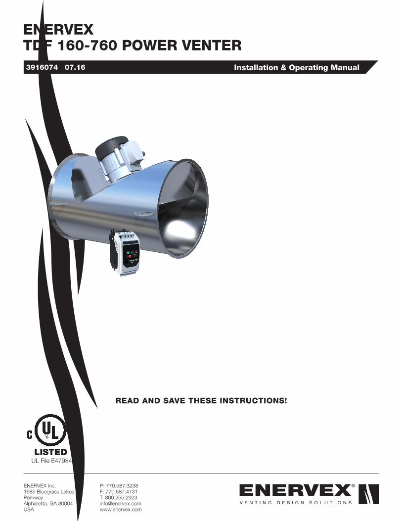
3916074 07.16 Installation & Operating Manual
ENERVEXTDF 160-760 POWER VENTER
READ AND SAVE THESE INSTRUCTIONS!
UL File E479840

2
3916074 07.16
Symbol LegendThe following terms are used throughout this manual to bring attention to the presence of potential hazards, or to important information concerning the product.
DANGER: Indicates an imminent hazardous situation which, if not avoided, will result in death, serious injury or substantial property damage.
WARNING: Indicates an imminent hazardous situation which, if not avoided, may result in personal injury or property damage.
DANGER: Indicates an imminent electrical shock hazard which, if not avoided, will result in death, serious injury or substantial property damage.
How to use this manual This installation manual does not contain any system design documentation. System design documentation is available from any authorized ENERVEX representative. Accessories, power venters, and variable frequency drives are not covered by this manual. Please refer to these component’s individual manuals.
TO REDUCE THE RISK OF FIRE, ELECTRICAL SHOCK OR INJURY TO PERSONS, OBSERVE THE FOLLOWING:
1. Use this unit in the manner intended by the manufacturer. If you have questions, contact the manufacturer at the address or telephone number listed on the front of the manual.
2. Before servicing or cleaning the unit, switch off at service panel and lock service panel to prevent power from being switched on accidentally.
3. Installation work and electrical wiring must be done by a qualified person(s) in accordance with applicable codes and standards.
4. Follow the appliance manufacturer’s guidelines and safety standards such as those published by the National Fire Protection Association (NFPA), and the American Society for Heating, Refrigeration and Air Conditioning Engineers (ASHRAE), and the local code authorities.
5. This unit must be grounded.
This symbol shows that ENERVEX TDF Power Venters are listed under Category Codes MCQX and ZACT.
UL File E467733

3
3916074 07.16
1. GENERAL INFORMATION 1.1 Introduction ......................................................4 1.2 Features ...........................................................4 1.3 Components ....................................................4 1.4 Shipping ...........................................................5 1.5 Accessories ......................................................5 1.6 Listings .............................................................5 1.7 Warranty ...........................................................52. SPECIFICATIONS AND DIMENSIONS 2.1 Specifications ...................................................6 2.2 Capacities .........................................................73. MECHANICAL INSTALLATION 3.1 General .............................................................8 3.2 Positioning ........................................................8 3.3 Drain Installation ................................................8 3.4 Mounting of Power Venter ................................8 3.5 Location / Connections .....................................9 3.6 Vertical Installation .............................................9 3.7 Outdoor Termination .........................................9 3.8 Installation of Rain Guard ..................................9 3.9 Field Junction Box ............................................94. ELECTRICAL INSTALLATION 4.1 General .............................................................10 4.2 Motor Controller Installation ..............................10 4.3 Mounting of EDrive Motor Controller .................11 4.4 Grounding Guidelines .......................................11 4.5 EMC Filter Disconnect ......................................11 4.6 Electrical Connection of Motor and EDrive ........12 4.7 Wiring Diagram - TDF 160-250 / 1x120V..........13 4.8 Wiring Diagram - TDF 560-685 / 3x208-480V ..13 4.9 Checking and Changing Rotation of Impeller ....14 4.10 Installing a Proven Draft Switch .......................14 4.11 Installation of Stack Probe for PDS Function ...145. STARTUP AND CONFIGURATION 5.1 General .............................................................15 5.2 System Testing .................................................15 5.3 EDrive Commissioning ......................................15 5.4 Resetting the EDrive to Factory Default .............17 5.5 Adjusting Fan Speed ........................................17 5.6 Testing Safety System ......................................17
Content
WARNINGThis product is equipped with an electronically commutated (EC-motor) and can not be connected directly to ac mains. Motor must be
connected to approved motor controller to ensure proper function. Failure to use approved motor controller may result in damage to the motor.
!
6. MAINTENANCE AND TROUBLESHOOTING 6.1 Cleaning Intervals ..............................................18 6.2 Cleaning ...........................................................18 6.3 Service..............................................................18 6.4 Replacement Parts Ordering .............................197. WARRANTY TERMS .............................................20
4
3916074 07.16
1. GENERAL INFORMATION
1.1 INTRODUCTIONThese instructions provide both general guidelines and special requirements for all parts in the TDF Power Venter product line. Before specifying a design or beginning an installation please carefully review these instructions. Contact local building or fire officials about restrictions and installation inspection in your area.
1.2 FEATURESThe TDF Power Venter is an efficient, high-temperature draft inducer with backward-curved centrifugal impeller. Typical application is the mechanical venting of gas-fired or oil-fired boilers and water heaters - condensing or non-condensing.
It can be installed horizontally or vertically in a chimney system.
The TDF is equipped with an air cooled, maintenance-free Electronicaly Commutated (EC) motor with pre-lubricated and sealed ball bearings, and includes a factory-programmed Edrive controller to control the motor operation.
The motor and controller is rated at 92% efficiency and able to operate as low as 90 RPM. The motor has integrated protection against overloading, blocking over and under voltage and over-heating.
The power venter housing and the backward inclined impelelr is made of 316L stainless steel. The motor and impeller is a complete assembly (drive unit) that can be removed from the power venter housing without removing the power venter from the stack system. The connections are 1/2” flanged type and fit most commercial pre-fabricated chimney systems. The power venter is typically installed hung from ceiling mounting brackets to support the weight.The TDF Power Venter r is a component in the CASI Chimney Automation System™.
The TDF model is approved for temperatures up to 1400°F (760°C).
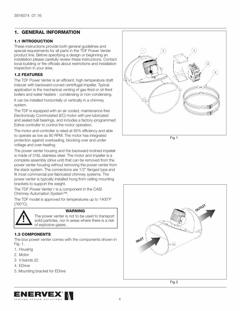
1.3 COMPONENTSThe box power venter comes with the components shown in Fig. 1.1. Housing2. Motor3 V-bands (2)4. EDrive5. Mounting bracket for EDrive
Fig 1
Fig 2
WARNINGThe power venter is not to be used to transport solid particles, nor in areas where there is a risk of explosive gases.
!

5
3916074 07.16
1.4 SHIPPINGTDF power venter units are shipped on a pallet and protected by a corrugated box.Do not place other products or items on top of the box.After unpacking, the product must be handled in a way to prevent damage to the collars and the power venter housing. The power venter is shipped with the motor installed on the access door with a dedicated motor controller. If other components are shipped, they will appear on the shipment packing list.NOTE: All power venters are shipped with a Field Junction Box connected via flexible conduit.
1.5 ACCESSORIES (Optional)• EBC 31 Modulating Pressure Control • Proven Draft Switch PDS
• Rain guard for outdoor installations
1.6 LISTINGS
UL Listing under Category MCQX is File No. E467733 and reference to the following standards:
UL 378 Standard For Draft Equipment Edition 4 - Revision Date 2013/09/17
ULC/ORD-C378-75 Guide For The Investigation Of Draft Equipment
ULC/ORD 2162 Commercial Wood-Fired Baking Ovens – Refractory Type Edition 1 - Issue Date 2013/06/01
UL705, Standard for Power Ventilators with special consideration for venting lint-laden air from single or multiple dryers and CSA 22.2 No. 113, Standard for Fans and Ventilators.CSA C22.2 NO. 113-12 Fans and Ventilators Edition 9 - Revision Date 2012/10/01
1.7 WARRANTY2-year factory warranty (see back cover). Complete warranty conditions are available from ENERVEX Inc.
CAUTIONThis duct power venter shall be installed a minimum of one meter from any accessible opening of the duct.
!CAUTION
Ce ventilateur de conduit doit être installé au moins un mètre d’une ouverture accessible du conduit.!
6
3916074 07.16
2. SPECIFICATIONS AND DIMENSIONS
2.1 SPECIFICATIONS
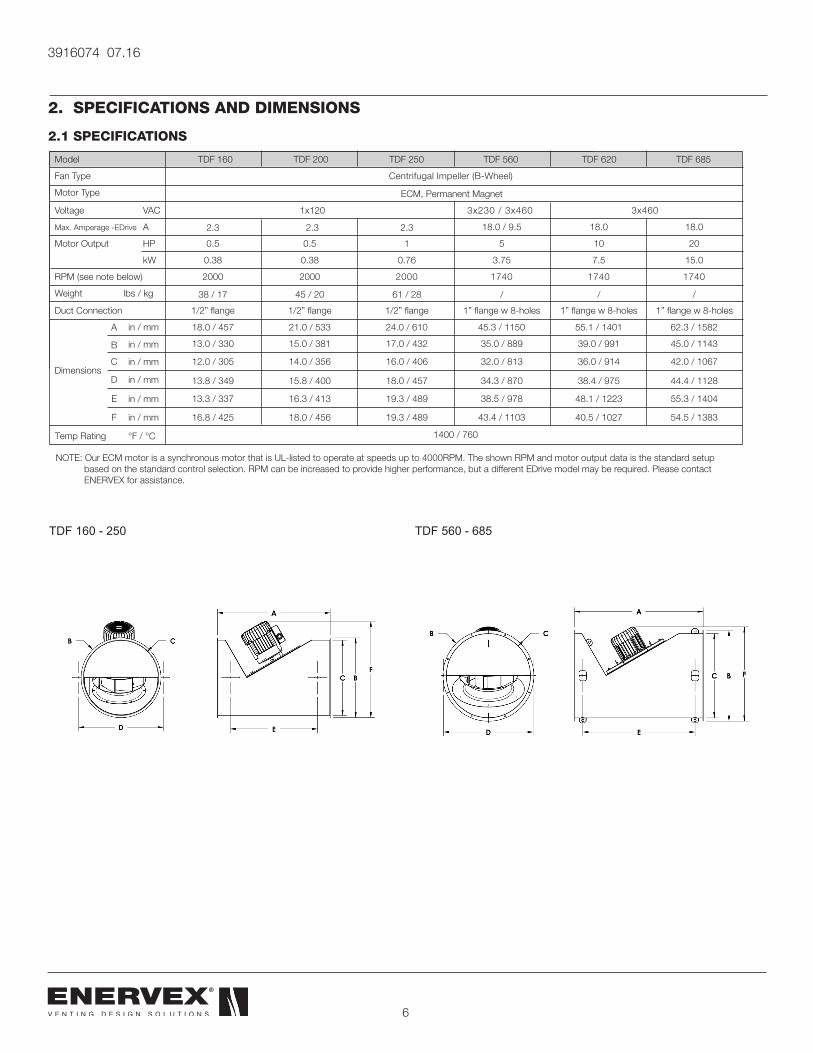
Model TDF 160 TDF 200 TDF 250 TDF 560 TDF 620 TDF 685
Fan Type Centrifugal Impeller (B-Wheel)
Motor Type ECM, Permanent Magnet
Voltage VAC 3x230 / 3x4601x120 3x460
Max. Amperage -EDrive A 18.0 / 9.5 18.0 18.0
Motor Output HP 0.50.5
2.32.3 2.3
51 10 20
kW 0.38 0.38 3.750.76 7.5 15.0
RPM (see note below) 2000 2000 2000 1740 1740 1740
38 / 17 45 / 20 61 / 28 / //Weight lbs / kg
Duct Connection
in / mm
in / mm
in / mm
1/2” �ange 1/2” �ange 1” �ange w 8-holes1/2” �ange 1” �ange w 8-holes 1” �ange w 8-holes
Dimensions
NOTE: Our ECM motor is a synchronous motor that is UL-listed to operate at speeds up to 4000RPM. The shown RPM and motor output data is the standard setup based on the standard control selection. RPM can be increased to provide higher performance, but a different EDrive model may be required. Please contact ENERVEX for assistance.
A 18.0 / 457 21.0 / 533 45.3 / 1150
B 13.0 / 330 15.0 / 381 35.0 / 889
C 12.0 / 305 14.0 / 356 32.0 / 813
24.0 / 610
17.0 / 432
16.0 / 406
55.1 / 1401 62.3 / 1582
39.0 / 991 45.0 / 1143
36.0 / 914 42.0 / 1067
in / mmD
in / mmE 13.3 / 337
in / mmF 16.8 / 425
16.3 / 413
18.0 / 456
19.3 / 489
19.3 / 489
38.5 / 978
43.4 / 1103
48.1 / 1223
40.5 / 1027
55.3 / 1404
13.8 / 349 15.8 / 400 18.0 / 457 34.3 / 870 38.4 / 975 44.4 / 1128
54.5 / 1383
°F / °C 1400 / 760Temp Rating
TDF 160 - 250 TDF 560 - 685

7
3916074 07.16
2.2 CAPACITIES
0.00
0.50
1.00
1.50
2.00
Ps
(in H
20)
Volume (CFM)0 100 200 300 400 500 600 700 800 900 1000
TDF 160
TDF 200
TDF 250
8.0
7.0
6.0
5.0
4.0
3.0
2.0
1.0
0.0
0 3,000 6,000 9,000 12,000 15,000 18,000 21,000
Inch
WC
CFM
CAPACITY CHARTENERVEX MODEL TDF685INLINE POWER VENTER
TDF 560
TDF 685
TDF 620
NOTE: Our ECM motor is a synchronous motor that is UL-listed to operate at speeds up to 4000RPM. The capacity charts are based on a standard setup operating at the RPM shown in the specification table. RPM can be increased to provide higher performance than shown here. Please contact ENERVEX for assistance

8
3916074 07.16
3. MECHANICAL INSTALLATION
3.1 GENERALThe TDF must be installed by a qualified installer in accordance with these instructions and all local codes, or in their absence, with the latest edition of The National Fuel Gas Code (NFPA54/ANSI223.1), NFPA 211, NFPA 31 or Canada CAN/CSA-B149.1-05 National Gas and Propane Installation Code when applicable. The TDF must be mounted so the clearance to combustibles is at least 18 inches.
Preferably, the TDF should be installed as close to the termination as possible as this offers more flexibility in the selection of chimney type. It can also be installed near the outlet of a heating appliance in the breeching itself. In addition, it can be used for sidewall vented applications where it discharges through a wall. A drain is provided with the TDF to be installed by the user.
The TDF is for indoor and outdoor installation. Unless installed adjacent to the wall it is discharging through, the chimney material used on the discharge side must be airtight/pressure rated. The chimney must be installed and supported according to the chimney manufacturer’s instructions and/or in accordance with NFPA54, NFPA211 and Canada CAN/CSA-B149.1-05. The TDF collars fit most commonly available vents and stacks.
The power venter can be oriented in multiple positions. Acceptable power venter orientations are shown in Fig 3. For outdoor Installations, the TDF can be mounted in positions A, B and D provided a Vertical Rain Guard (included) is installed above the motor. Installation in position C requires a Horizontal Rain Guard (optional).
3.2 POSITIONINGAcceptable power venter positions are shown in Fig. 3. If mounted horizontally, ENERVEX recommends that the motor be positioned in Fig. 3, position A or on the side as shown in Fig. 3, position B, when flue gas temperatures exceed 220°F (100°C). The TDF must be mounted to provide clear and easy access to the motor and impeller assembly.
NOTE: If the TDF is mounted in position B or C, a drain may be installed as described in Section 3.3.
3.3 DRAIN INSTALLATIONInstall the provided drain if the TDF is mounted horizontally. The drain should be installed near the inlet of the power venter and oriented so it points toward the ground.
3.4 MOUNTING OF POWER VENTERThe TDF has (4) 1” diameter mounting tabs on each end of the power venter. Threaded rod or steel hangers should run through these holes to hang the power venter from the ceiling or other support.
Fig 3
Fig 4
WARNINGThe ventilator motor should never hang downward. This can cause condensation build-up around the shaft, and can shorten the product life.
!
9
3916074 07.16
3.5 LOCATION/CONNECTIONSFollow the recommendations by the vent or stack manufacturer.
The TDF 160, 200 and 250 have 1/2” flanged connections.
The TDF 560, 620 and 685 have 8-bolt flange connections.
Transitions to most chimeny system types are available (not included).
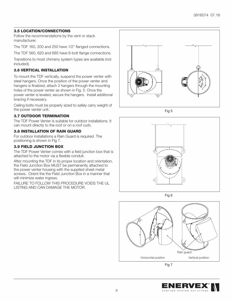
3.6 VERTICAL INSTALLATION
To mount the TDF vertically, suspend the power venter with steel hangers. Once the position of the power venter and hangers is finalized, attach 2 hangers through the mounting holes of the power venter as shown in Fig. 5. Once the power venter is leveled, secure the hangers. Install additional bracing if necessary.
Ceiling bolts must be properly sized to safely carry weight of the power venter unit.
3.7 OUTDOOR TERMINATION The TDF Power Venter is suitable for outdoor installations. It can mount directly to the roof or on a roof curb.
3.8 INSTALLATION OF RAIN GUARDFor outdoor installations a Rain Guard is required. The positioning is shown in Fig 7.
3.9 FIELD JUNCTION BOX The TDF Power Venter comes with a field junction box that is attached to the motor via a flexible conduit. After mounting the TDF in its proper location and orientation, the Field Junction Box MUST be permanently attached to the power venter housing with the supplied sheet metal screws. Orient the the Field Junction Box in a manner that will minimize water ingress. FAILURE TO FOLLOW THIS PROCEDURE VOIDS THE UL LISTING AND CAN DAMAGE THE MOTOR.
Fig 6
Fig 5
Fig 7
Vertical positionHorizontal position
Rain guard
10
3916074 07.16
4. ELECTRICAL INSTALLATION
4.1 GENERALAll wiring must be in compliance with the local codes or in their absence, with the National Electric Code, NFPA70. All wiring should be appropriate Class 1 wiring as follows: installed in rigid metal conduit, intermediate metal conduit, rigid non-metallic conduit, electrical metallic tubing, or be otherwise suitably protected from physical damage. All TDF units are equipped with an EC-motor and operate at different voltages so it’s important to pay attention to the wiring details.
Note: If any of the original wire supplied with the system must be replaced, use similar wire of the same temperature rating. Otherwise, insulation may melt or degrade, exposing bare wire.
4.2 MOTOR CONTROLLER INSTALLATIONAll ENERVEX TDF power venters come with, and must use, a factory programmed EDrive motor controller with an enclosure rated to NEMA 1/IP20. The EDrive motor controller must be mounted indoors, within 300 feet of the TDF Fan. This distance can be increased up to 600 feet with the addition of a line filter (Contact ENERVEX for details). If the EDrive motor controller must be mounted outdoors or in an unprotected area, it must be installed in a minimum NEMA 3R enclosure. A motor disconnect switch must be installed between the motor controller and the TDF Fan, either within sight of the TDF Fan, or within 50 feet of the TDF Fan. Do not activate the motor disconnect switch while the TDF motor is running - damage could occur to the motor controller.
WARNINGThis product is equipped with an electronically commutated (EC-motor) and can not be connected directly to ac mains. Motor must be connected to approved motor controller
to ensure proper function. Failure to use approved motor controller may result in damage to the motor.
!
WARNINGAll TDF models must be operated with the approved factory-programmed motor drive.DO NOT CONNECT DIRECTLY TO LINE VOLTAGE!
!
DANGERTurn off electrical power before servicing. Contact with live electric components can cause shock or death.
ABOUT SHAFT GROUNDINGBearing currents are very common problem of Variable Frequency Drives (VFD/Motor Controller) and electronic commutated motors. The electric-discharge machining (EDM) bearing currents are generated in motors because of unbalanced modulated voltage from drive to the motor. Because of stray capacitances in motor, bearing currents are generated in rotor and there is usually no other way to discharge except through bearings. This drastically lowers the life time of the bearings.The TDF’s EC-motor integrates an insulated rotor system, which means that electrical insulation is inserted between rotor and motor shaft. This system provide up to 80% lower shaft voltages and very low bearing current values which eliminates bearing damage.
DANGERThe motor speed drive is suitable for use in a circuit capable of receiving not more than 100 KA RMS symmetrical Amperes at the maximum reated voltage.

11
3916074 07.16
4.3 MOUNTING OF EDRIVE MOTOR CONTROLLERMount the EDrive motor controller in a location that is only accessible to qualified personal.The EDrive must be installed within 300 ft of the TDF Fan.Use the included mounting bracket to provide conduit landing and to provide a degree of protection from falling dirt.Mount the EDrive to the bracket on the center DIN rail. Secure drive using included #6 sheet metal screws. See Fig 84.4 GROUNDING GUIDELINESThe ground terminal of an EDrive must be individually connected DIRECTLY to the site ground bus bar (through the filter if installed). EDrive ground connections should not loop from one drive to another, or to, or from any other equipment.Ground loop impedance must conform to local codes. To meet UL regulations, UL approved ring crimp terminals should be used for all ground wiring connections.The drive Safety Ground must be connected to system ground. Ground impedance must conform to the requirements of local codes. Protective Earth ConductorThe Cross sectional area of the ground conductor must be at least equal to that of the incoming supply conductor.Safety GroundThis is the safety ground for the drive that is required by code. One of these points must be connected to adjacent building steel (girder, joist), a floor ground rod, or bus bar. Grounding points must comply with local codes.Motor GroundThe motor ground must be connected to one of the ground terminals on the drive.Ground Fault MonitoringAs with all inverters, a leakage current to earth can exist. The EDrive is designed to produce the minimum possible leakage current while complying with worldwide standards. The level of current is affected by motor cable length and type, the effective switching frequency, the ground connections used and the type of RFI filter installed.
4.5 EMC FILTER DISCONNECTDrives with an EMC filter have an inherently higher leakage current to Ground. For applications where tripping occurs, the EMC filter can be disconnected by completely removing the EMC screw on the side of the product. See Fig 9.The EDrive product range has input supply voltage surge suppression components fitted to protect the drive from line voltage transients, typically originating from lightning strikes or switching of high power equipment on the same supply.When carrying out a HiPot (Flash) test on an installation in which the drive is built, the voltage surge suppression components may cause the test to fail.
WARNINGFor installation in the United States, branch circuit protection must be provided in accordance with the National Electrical Code (NEC).
!
CAUTIONFor installation in Canada, branch circuit protection must be provided in accordance with the Canadian Electrical code Pour l’installation au Canada, la protection de
circuit de branche doit être fournie conformément au Le code canadien de l’électriticé.
!
DANGEROnly qualified electrical personnel familiar with the construction and operation of this equipment and the hazards involved should install, adjust, operate, or service this
equipment. Read and understand this manual and other applicable manuals in their entirety before proceeding. Failure to observe this precaution could result in severe bodily injury or loss of life.
Fig 8
Fig 9
12
3916074 07.16
4.6 ELECTRICAL CONNECTION OF THE MOTOR AND EDRIVEThe motor should be connected to the EDrive U, V, and W terminals using a suitable 3 or 4 conductor cable. Where a 3 conductor cable is used, with the shield operating as an earth conductor, the shield must have a cross sectional area at least equal to the phase conductors when they are made from the same material. Where a 4 conductor cable is used, the earth conductor must be of at least equal cross sectional area.The motor ground must be connected to one of the EDrive ground terminals.For compliance with the EMC directive, a suitable shielded cable should be used. Braided or twisted type shielded cable where the shield covers at least 85% of the cable surface area, designed with low impedance to HF signals, are recommended as a minimum. Installation within a suitable steel or copper tube is generally also acceptable. The cable shield should be terminated at the motor end using an EMC type fitting allowing connection to the motor body through the largest possible surface area. .The TDF Fan sizes 200-500 require four (4) 14GA conductors between the EDrive and the Fan motor. (Three (3) Power lines, and one (1) dedicated Ground wire.)The TDF Fan Sizes 600-700 require four (4) 12GA conductors between the EDrive and the Fan motor. (Three (3) Power lines, and one (1) dedicated Ground wire.)Make all necessary connections to the power and low-voltage terminals (see wiring diagram).for the power venter to operate with improper rotation. However, the power venter will only provide 25–30% of full capacity, will cause damage to components and should be avoided. Fan rotation can be changed on the EDrive, by removing the jumper over terminals 2 and 3.
DANGERThis EDrive contains high voltage capacitors that take time to discharge after removal of the main supply. Before working on the drive, ensure isolation of the main supply from line
inputs. Wait ten (10) minutes for the capacitors to discharge to safe voltage levels. Failure to observe this precaution could result in severe bodily injury or loss of life.
13
3916074 07.16
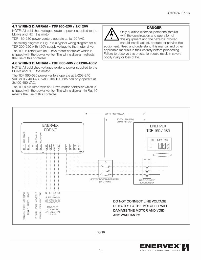
Fig 10
4.7 WIRING DIAGRAM - TDF160-250 / 1X120VNOTE: All published voltages relate to power supplied to the EDrive and NOT the motor. TDF 160-250 power venters operate at 1x120 VAC. The wiring diagram in Fig. 7 is a typical wiring diagram for a TDF 200-250 with 120V supply voltage to the motor drive.The TDF is listed with an EDrive motor controller which is shipped with the power venter. The wiring diagram reflects the use of this controller.
4.8 WIRING DIAGRAM - TDF 560-685 / 3X208-480VNOTE: All published voltages relate to power supplied to the EDrive and NOT the motor. The TDF 560-620 power venters operate at 3x208-240 VAC or 3 x 400-480 VAC. The TDF 685 can only operate at 3x400-480 VAC.The TDFs are listed with an EDrive motor controller which is shipped with the power venter. The wiring diagram in Fig. 10 reflects the use of this controller.
1 G7632 L2N
L1 L3 U V W G U1 V1 W1
ENERVEXEDRIVE
ENERVEXTDF 160 / 685
BEF MOTOR
SERVICE DISCONNECT SWITCH(BY OTHERS)
FIELD CONNECTJUNCTION BOX
24VD
C O
UT - E
BC
31 TER
M 35
24VD
C O
UT
STA
RT - E
BC
31 TER
M 36
0-10VD
C IN
- EB
C31 TE
RM
37
GN
D / C
OM
- EB
C31 TE
RM
38
STA
RT
0-10VD
C IN
GN
D / C
OM
G L2/N
L1 L3
SUPPLY MAINS200-240/3/50-60380-480/3/50-60
120/1/50-60L1 = PHASE
L2/N = NEUTRALL3 = NA
300 FT / 100 M (MAX)
50 FT / 15 M (MAX)OR WITHIN SIGHT
DANGEROnly qualified electrical personnel familiar with the construction and operation of this equipment and the hazards involved should install, adjust, operate, or service this
equipment. Read and understand this manual and other applicable manuals in their entirety before proceeding. Failure to observe this precaution could result in severe bodily injury or loss of life.
DO NOT CONNECT LINE VOLTAGEDIRECTLY TO THE MOTOR. IT WILLDAMAGE THE MOTOR AND VOID ANY WARRANTY!

14
3916074 07.16
Fig 8
4.9 CHECKING AND CHANGING ROTATION OF IMPELLERTo check the rotation of the impeller, visuallly check the motor rotation an dmake sure it matches the rotation arrow. See Fig. 11.It is possible for the power venter to operate with improper rotation. However, the power venter will only provide 25–30% of full capacity, will cause damage to components and should be avoided. Fan rotation can be changed on the EDrive by switching the attachment position of any two power leads.
4.10 INSTALLING A PROVEN FLOW SYSTEMIf required by local codes, a safety system can be interlocked with the appliance(s) to prove power venter operation. The safety system could utilize a Proven Draft Switch (PDS), a thermal switch, a flow switch or a sail switch. The device must be interlocked with the appliance(s) so it shuts down in case of power venter failure or power failure.Please refer to the PDS Installation Manual for wiring instructions. If the installation includes an EBC 30/31 Modulating Pressure Fan Control, a PDS is not required as the function is integrated into the control.
4.11 INSTALLATION OF STACK PROBE FOR PDS FUNCTIONInstall the probe for the Proven Draft Switch (PDS) in a vent connector, at the end of the commom manifold or at another point where. The probe must be located between the appliance and the power venter.
Preferably, the probe should be located so dimension “A” is at least 3 vent diameters from a change of direction, a draft hood, a draft diverter, or a barometric damper. If layout does not allow proper location, it may have an impact on performance. See Fig 12.
The tip of the probe MUST be flush with the inner chimney wall to get a proper pressure reading.
CAUTIONALa turbine doit impérativement tourner dans le bon sens. Une rotation en sens inverse entraînerait de mauvaises performances de soufflage, une surcharge
du moteur voire un grillage du moteur.
!
WARNINGCorrect direction of wheel rotation is critical. Reversed rotation will result in poor air performance, motor overloading and possible burnout.
!
Fig 12
Fig 11

15
3916074 07.16
NAVIGATEUsed to display real-time information, to access and exit parameter edit mode and to store parameter changes
UPUsed to increase speed in real-time mode or to increase parameter values in parameter edit mode
DOWNUsed to decrease speed in real-time mode or to decrease parameter values in parameter edit mode
RESET / STOP
Used to reset a tripped drive. When in Keypad mode is used to Stop a running drive.
STARTWhen in keypad mode, used to Start a stopped drive or to reverse the direction of rotation if bi-directional keypad mode is enabled
Fig 13
5. STARTUP AND CONFIGURATION
5.1 GENERALBefore commissioning the system, make sure the EDrive is properly wired to the Fan motor. Failure to do this will prevent proper commissioning.
5.2 SYSTEM TESTING1. Check the line voltage with the motor name plate rating.
2. Check to ensure transport securing device (if applicable) holding the motor shaft and impeller in place has been removed.
3. Determine if impeller is running free and properly aligned.
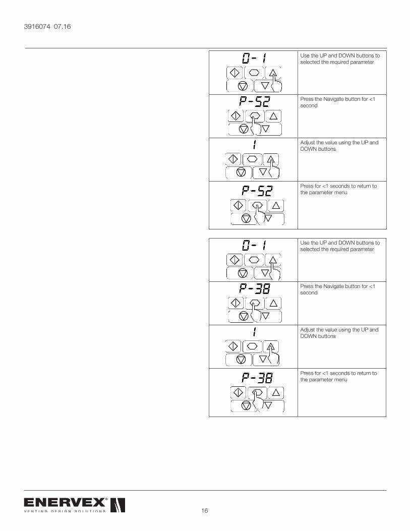
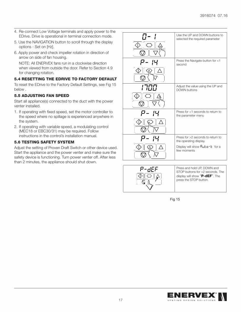
5.3 EDRIVE COMMISSIONING1. Disconnect Low Voltage Terminal (1)2. Apply power to the EDrive3. Make sure the EDrive is set for Auto-tuning. Check the following Parameters (see Fig 13 for keypad management) to make for the proper values: P-53 = 100 P-52 = 1 P-38 = 1 P-14 = 1700
Follow step-by-step instructions in Fig 14:Press and hold the Navigate button >2 seconds
Use the UP and DOWN buttons to selected the required parameter
Press the Navigate button for <1 second
Adjust the value using the UP and DOWN buttons
Press for <1 seconds to return to the parameter menu
Fig 14
16
3916074 07.16
Use the UP and DOWN buttons to selected the required parameter
Press the Navigate button for <1 second
Adjust the value using the UP and DOWN buttons
Press for <1 seconds to return to the parameter menu
Use the UP and DOWN buttons to selected the required parameter
Press the Navigate button for <1 second
Adjust the value using the UP and DOWN buttons
Press for <1 seconds to return to the parameter menu
17
3916074 07.16
Use the UP and DOWN buttons to selected the required parameter
Press the Navigate button for <1 second
Adjust the value using the UP and DOWN buttons
Press for <1 seconds to return to the parameter menu
Press for >2 seconds to return to the operating display.
Display will show Auto-t for a few moments
4. Re-connect Low Voltage terminals and apply power to the EDrive. Drive is operational in terminal connection mode.
5. Use the NAVIGATION button to scroll through the display options - Set on [Hz].
6. Apply power and check impeller rotation in direction of arrow on side of fan housing.
NOTE: All ENERVEX fans run in a clockwise direction when viewed from outside the door. Refer to Section 4.9 for changing rotation.
5.4 RESETTING THE EDRIVE TO FACTORY DEFAULTTo reset the EDrive to the Factory Default Settings, see Fig 15 below .
5.5 ADJUSTING FAN SPEEDStart all appliance(s) connected to the duct with the power venter installed.
1. If operating with fixed speed, set the motor controller to the speed where no spillage is experienced anywhere in the system.2. If operating with variable speed, a modulating control (MEC18 or EBC30/31) may be required. Follow instructions in the control’s installation manual.
5.6 TESTING SAFETY SYSTEMAdjust the setting of Proven Draft Switch or other device used.Start the appliance and the power venter and make sure the safety device is functioning. Turn power venter off. After less than 2 minutes, the appliance should shut down.
Press and hold UP, DOWN and STOP buttons for >2 seconds. The display will show “P-dEF”. The press the STOP button.
Fig 15
18
3916074 07.16
6. MAINTENANCE AND TROUBLESHOOTING
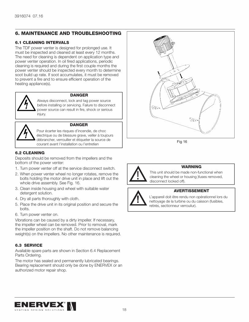
6.1 CLEANING INTERVALSThe TDF power venter is designed for prolonged use. It must be inspected and cleaned at least every 12 months. The need for cleaning is dependent on application type and power venter operation. In oil fired applications, periodic cleaning is required and during the first couple months the power venter should be inspected every month to determine soot build up rate. If soot accumulates, it must be removed to prevent a fire and to ensure efficient operation of the heating appliance(s).
6.2 CLEANINGDeposits should be removed from the impellers and the bottom of the power venter:1. Turn power venter off at the service disconnect switch.2. When power venter wheel no longer rotates, remove the bolts holding the motor drive unit in place and lift out the whole drive assembly. See Fig. 16.3. Clean inside housing and wheel with suitable water detergent solution.4. Dry all parts thoroughly with cloth.5. Place the drive unit in its original position and secure the bolts.6. Turn power venter on.Vibrations can be caused by a dirty impeller. If necessary, the impeller wheel can be removed. Prior to removal, mark the impeller position on the shaft. Do not remove balancing weight(s) on the impellers. No other maintenance is required.
6.3 SERVICEAvailable spare parts are shown in Section 6.4 Replacement Parts Ordering.The motor has sealed and permanently lubricated bearings. Bearing replacement should only be done by ENERVEX or an authorized motor repair shop.
Fig 10
DANGERAlways disconnect, lock and tag power source before installing or servicing. Failure to disconnect power source can result in fire, shock or serious injury.
AVERTISSEMENTL’appareil doit être rendu non opérationnel lors du nettoyage de la turbine ou du caisson (fusibles, retirés, sectionneur verrouilur).
!
WARNINGThis unit should be made non-functional when cleaning the wheel or housing )fuses removed, disconnect locked off).
DANGERPour écarter les risques d’incendie, de choc électrique ou de blessure grave, veiller à toujours débrancher, verrouiller et étiqueter la source de courant avant l’installation ou l’entretien
Fig 16
19
3916074 07.16
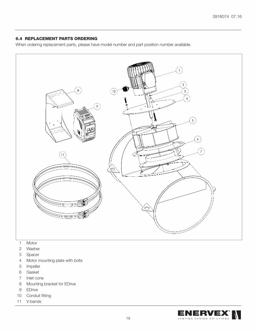
6.4 REPLACEMENT PARTS ORDERINGWhen ordering replacement parts, please have model number and part position number available.
1 Motor 2 Washer 3 Spacer 4 Motor mounting plate with bolts 5 Impeller 6 Gasket 7 Inlet cone 8 Mounting bracket for EDrive 9 EDrive 10 Conduit fitting 11 V-bands

ENERVEX Inc.1685 Bluegrass Lakes Parkway Alpharetta, GA 30004USA
P: 770.587.3238 F: 770.587.4731 T: 800.255.2923 [email protected] www.enervex.com
3001
807
12.
15
ENERVEX warrants the TDF Ventilator Fan against functional failure due to defects in material and workmanship for a period of two (2) years from date of delivery to the construction site. Functional failure is defined as any failure of the power venter to perform its intended function of exhausting grease-laden and creosote-laden exhaust. During this period, any TDF Ventilator Fan supplied by ENERVEX failing to perform its intended function will be repaired or replaced, at the manufacturer’s option, following determination by a factory authorized inspector that a functional failure has occurred.
This warranty is limited to repair or replacement of the product (including, but not limited to, motor and housing) plus shipping cost to the failure location. This warranty does not cover any labor cost for removal or replacement of the defective product nor does this warranty cover any component not furbished by ENERVEX and installed as part of the system.
This warranty is a two-way agreement. ENERVEX promises to supply free replacements as stated, but the user agrees that, except for our obligation to make good on this promise, ENERVEX shall not be responsible for any expense or inconvenience which the user might incur or experience with respect to the product, nor shall ENERVEX be liable for defects, damage or failures, caused by unauthorized alterations, unreasonable use, accident or abuse, including
failure to provide reasonable and necessary maintenance, after the product has been delivered. Some states do not allow the exclusion or limitation of incidental or consequential damages, so the above limitations or exclusions may not apply to you.
ENERVEX assumes no liability for incidental or consequential damages of any kind or for any damages resulting in whole or in part from misuse, improper installation, or inadequate maintenance of the system or any component part thereof. This warranty is in lieu of all other express warranties or guarantees of any kind. All implied warranties, including merchantability and fitness, are limited to the duration of the express warranty contained herein. ENERVEX neither assumes nor does it authorize any other person to assume on its behalf any other liability in connection with the sale of its product.
In addition, we promise the original user that we will replace or repair as we may elect, any parts or parts of the ENERVEX chimney power venter which are perforated due to corrosion without charge for parts or labor (not including dismantling, installation, freight, etc.) during the first 10 years following the date of installation.
For prompt warranty service, contact the ENERVEX Customer Service Department, 1685 Bluegrass Lakes Parkway, Alpharetta, GA 30004.
7. WARRANTY TERMS – TDF