Embed Size (px)
Citation preview

7/31/2019 Engineering and Planning Dwdm
http://slidepdf.com/reader/full/engineering-and-planning-dwdm 1/14
1
ENGINEERING AND PLANNINGDWDM
7/31/2019 Engineering and Planning Dwdm
http://slidepdf.com/reader/full/engineering-and-planning-dwdm 2/14
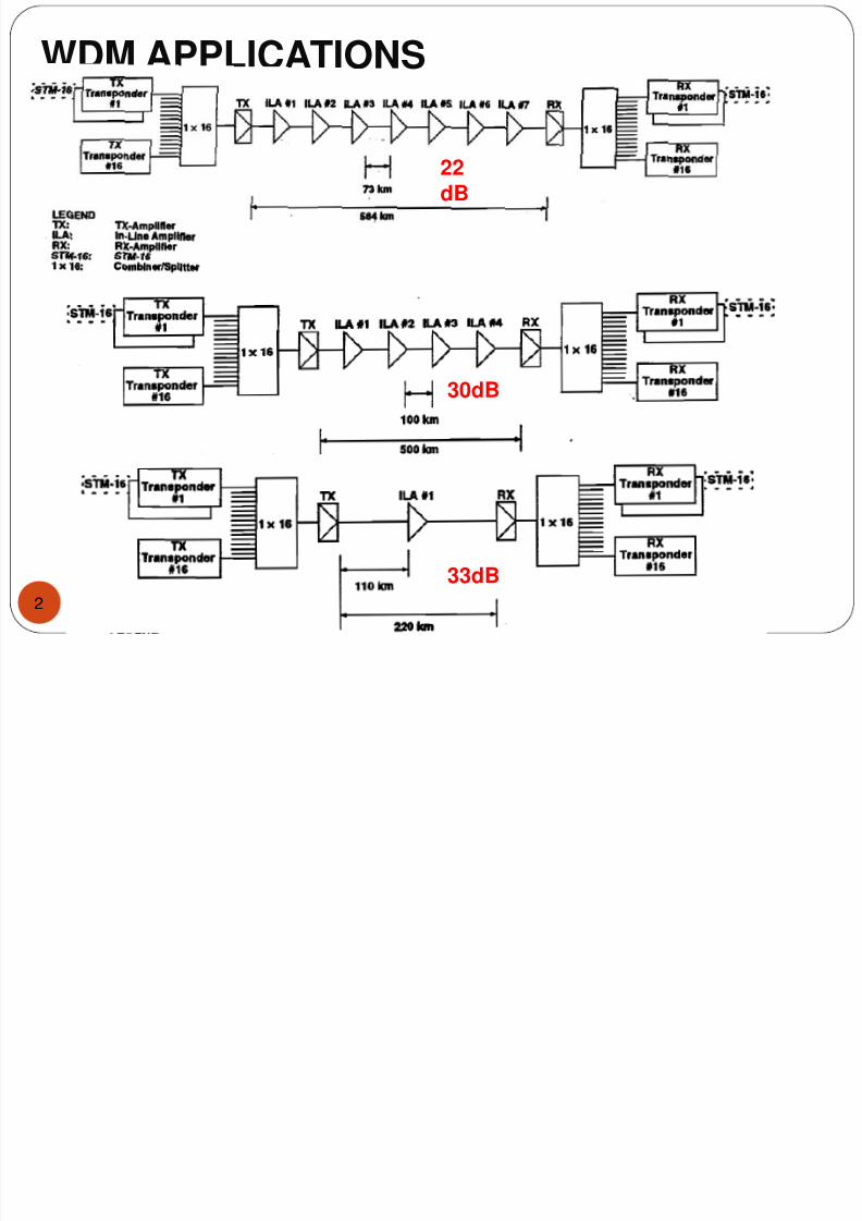
WDM APPLICATIONS
2
22dB
30dB
33dB

7/31/2019 Engineering and Planning Dwdm
http://slidepdf.com/reader/full/engineering-and-planning-dwdm 3/14
Aplicaciones en Tandem
3
Caso: El numero de repetidores llega al maximo, se utiliza un “back-to-back”
7/31/2019 Engineering and Planning Dwdm
http://slidepdf.com/reader/full/engineering-and-planning-dwdm 4/14
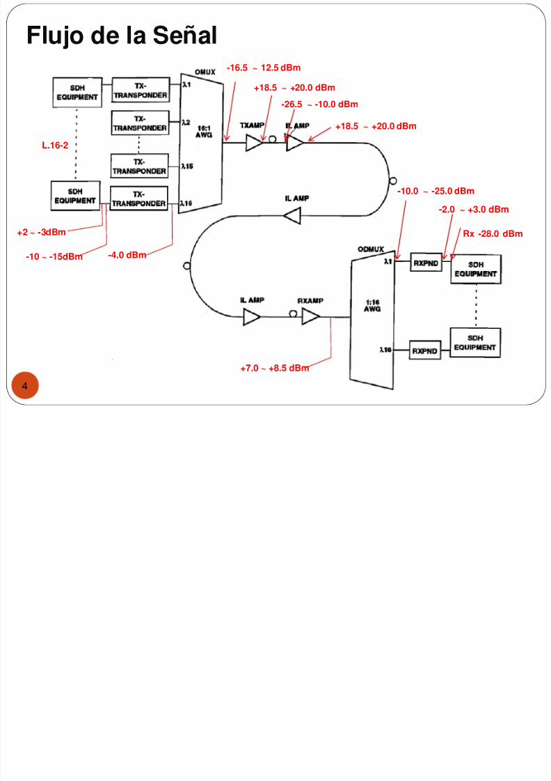
Flujo de la Señal
4
+2 ~ -3dBm
-10 ~ -15dBm
L.16-2
-4.0 dBm
-16.5 ~ 12.5 dBm
+18.5 ~ +20.0 dBm
-26.5 ~ -10.0 dBm
+18.5 ~ +20.0 dBm
-10.0 ~ -25.0 dBm-2.0 ~ +3.0 dBm
Rx -28.0 dBm
+7.0 ~ +8.5 dBm
7/31/2019 Engineering and Planning Dwdm
http://slidepdf.com/reader/full/engineering-and-planning-dwdm 5/14
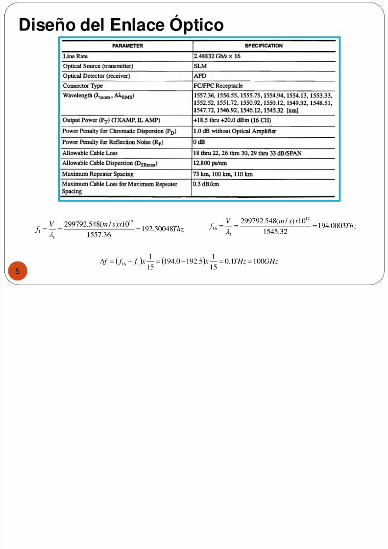
Diseño del Enlace Óptico
5
Thz xsmV
f 50048.19236.1557
10) / (548.299792 12
1
1
Thz xsmV
f 0003.19432.1545
10) / (548.299792 12
1
16
GHzTHz x x f f f 1001.0
15
15.1920.194
15
1116

7/31/2019 Engineering and Planning Dwdm
http://slidepdf.com/reader/full/engineering-and-planning-dwdm 6/14
Especificación del Diseño de Sistema
6
f
o
P
Ch xPdBm
Re
16log105.18 16 Canales
f
o
P
PdBm
Re
log1046.6 1 Canal
7/31/2019 Engineering and Planning Dwdm
http://slidepdf.com/reader/full/engineering-and-planning-dwdm 7/14
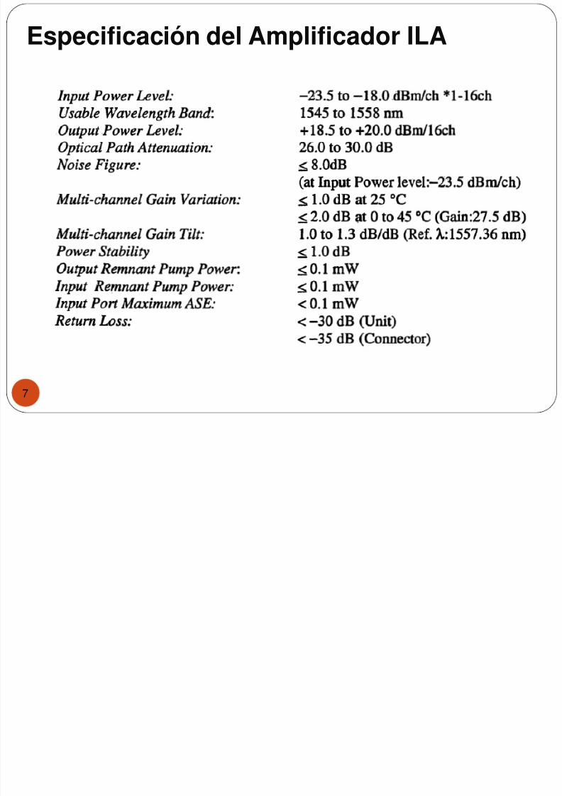
Especificación del Amplificador ILA
7
7/31/2019 Engineering and Planning Dwdm
http://slidepdf.com/reader/full/engineering-and-planning-dwdm 8/14
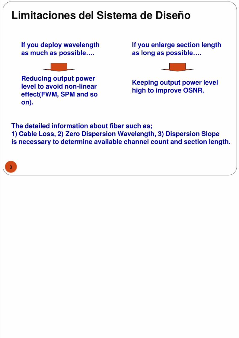
Limitaciones del Sistema de Diseño
8
If you deploy wavelengthas much as possible….
If you enlarge section lengthas long as possible….
Reducing output powerlevel to avoid non-lineareffect(FWM, SPM and soon).
Keeping output power levelhigh to improve OSNR.
The detailed information about fiber such as;1) Cable Loss, 2) Zero Dispersion Wavelength, 3) Dispersion Slopeis necessary to determine available channel count and section length.
7/31/2019 Engineering and Planning Dwdm
http://slidepdf.com/reader/full/engineering-and-planning-dwdm 9/14
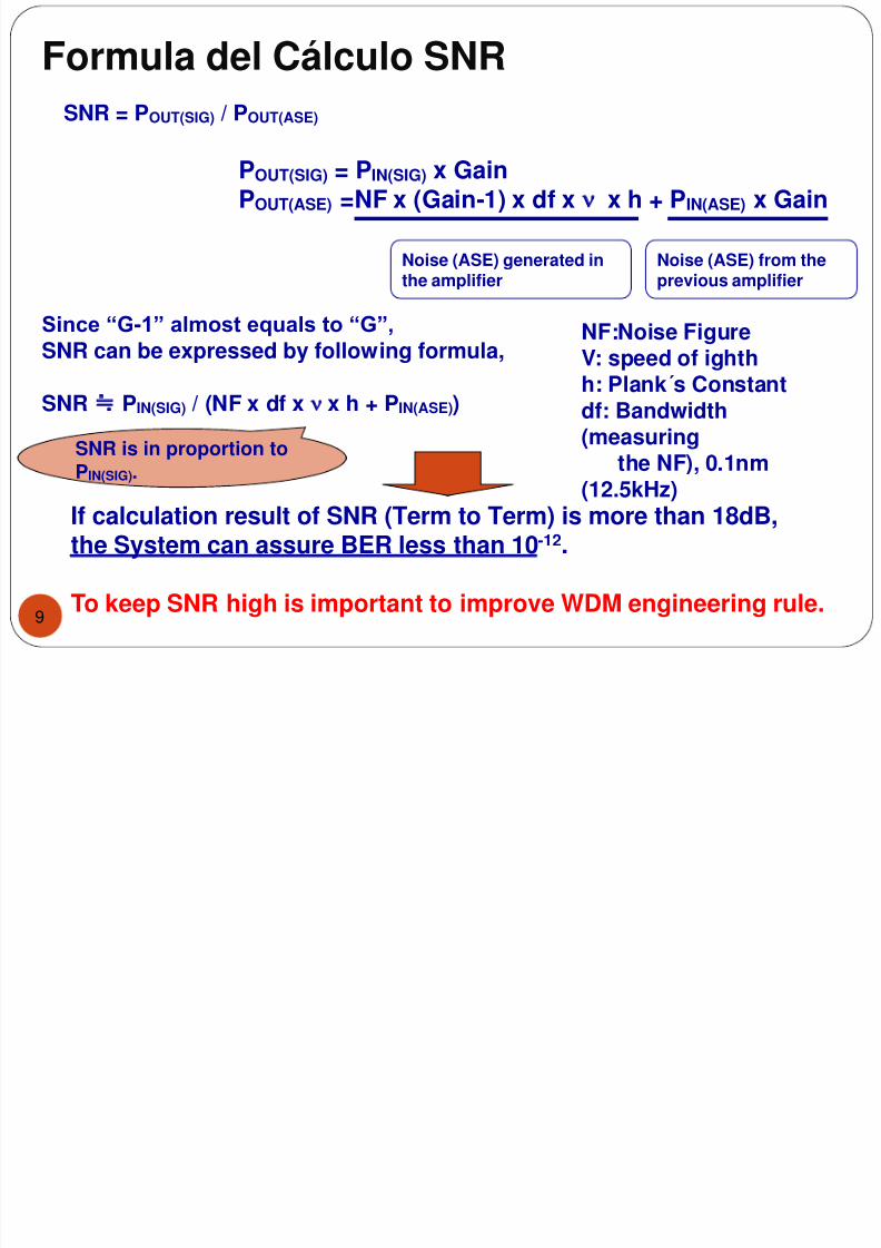
Formula del Cálculo SNR
9
Since “G-1” almost equals to “G”,
SNR can be expressed by following formula,
SNR PIN(SIG) / (NF x df x x h + PIN(ASE))
SNR = POUT(SIG) / POUT(ASE)
POUT(SIG) = PIN(SIG) x GainPOUT(ASE) =NF x (Gain-1) x df x x h + PIN(ASE) x Gain
Noise (ASE) generated inthe amplifier
Noise (ASE) from theprevious amplifier
If calculation result of SNR (Term to Term) is more than 18dB,the System can assure BER less than 10-12.
To keep SNR high is important to improve WDM engineering rule.
SNR is in proportion toPIN(SIG).
NF:Noise FigureV: speed of ighthh: Plank´s Constantdf: Bandwidth(measuring
the NF), 0.1nm(12.5kHz)
7/31/2019 Engineering and Planning Dwdm
http://slidepdf.com/reader/full/engineering-and-planning-dwdm 10/14
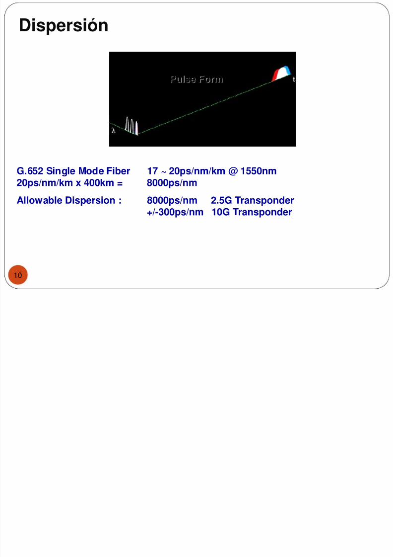
Dispersión
10
Pulse Form
G.652 Single Mode Fiber 17 ~ 20ps/nm/km @ 1550nm20ps/nm/km x 400km = 8000ps/nm
Allowable Dispersion : 8000ps/nm 2.5G Transponder+/-300ps/nm 10G Transponder
7/31/2019 Engineering and Planning Dwdm
http://slidepdf.com/reader/full/engineering-and-planning-dwdm 11/14
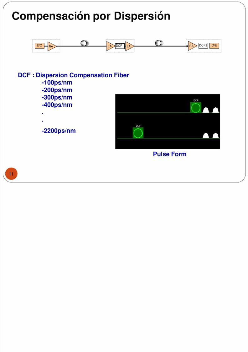
Compensación por Dispersión
11
DCF : Dispersion Compensation Fiber-100ps/nm-200ps/nm-300ps/nm-400ps/nm..
-2200ps/nm
Pulse Form
PA O/EDCF2E/O BA DCF1 LALA
7/31/2019 Engineering and Planning Dwdm
http://slidepdf.com/reader/full/engineering-and-planning-dwdm 12/14
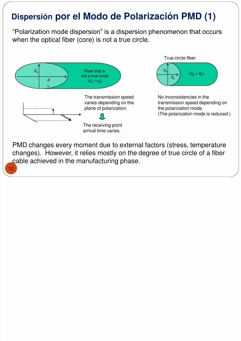
Dispersión por el Modo de Polarización PMD (1)
12
“Polarization mode dispersion” is a dispersion phenomenon that occurs
when the optical fiber (core) is not a true circle.
da
d
b
da
db
(da = db)
True circle fiber
The transmission speedvaries depending on theplane of polarization.
The receiving pointarrival time varies.
No inconsistencies in thetransmission speed depending onthe polarization mode.(The polarization mode is reduced.)
PMD changes every moment due to external factors (stress, temperaturechanges). However, it relies mostly on the degree of true circle of a fibercable achieved in the manufacturing phase.
Fiber that isnot a true circle
(da db)
7/31/2019 Engineering and Planning Dwdm
http://slidepdf.com/reader/full/engineering-and-planning-dwdm 13/14
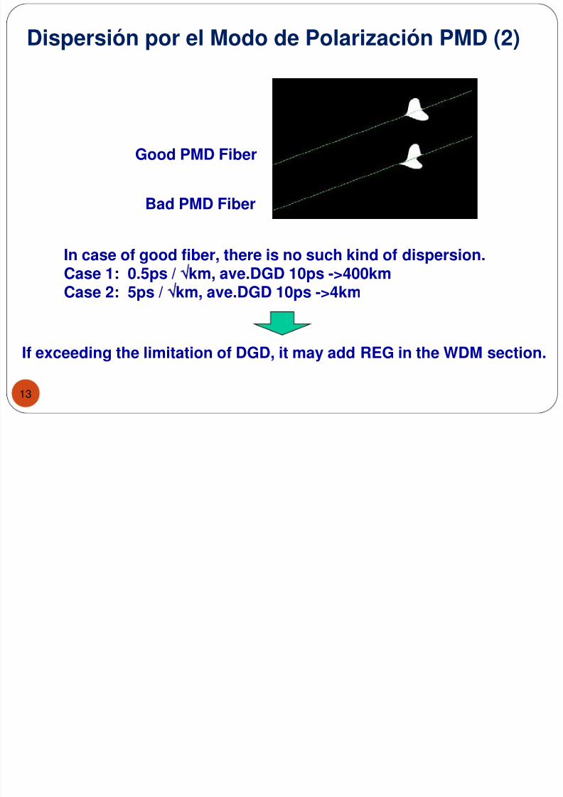
Dispersión por el Modo de Polarización PMD (2)
13
In case of good fiber, there is no such kind of dispersion.Case 1: 0.5ps / km, ave.DGD 10ps ->400km
Case 2: 5ps / km, ave.DGD 10ps ->4km
Good PMD Fiber
Bad PMD Fiber
If exceeding the limitation of DGD, it may add REG in the WDM section.
7/31/2019 Engineering and Planning Dwdm
http://slidepdf.com/reader/full/engineering-and-planning-dwdm 14/14
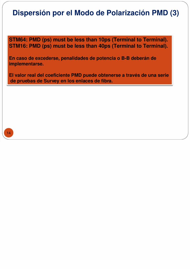
Dispersión por el Modo de Polarización PMD (3)
14
STM64: PMD (ps) must be less than 10ps (Terminal to Terminal).STM16: PMD (ps) must be less than 40ps (Terminal to Terminal).
En caso de excederse, penalidades de potencia o B-B deberán deimplementarse.
El valor real del coeficiente PMD puede obtenerse a través de una seriede pruebas de Survey en los enlaces de fibra.