Embed Size (px)
Citation preview
Topographical SurveyingSr Tan Liat Choon
Email: [email protected]
Mobile: 016-4975551
ENGINEERING SURVEYING (221 BE)
Topographic Survey
Two types of topographic survey:
Area surveys• Area survey have appreciable width as well as length
Route surveys• Route surveys provide strip maps for the location of
railroads, highways, pipelines, transmission lines,
canals, etc.
Topographic Survey
A survey conducted to determined the configuration of the ground
Collecting data and preparing maps showing the locations of natural man-made features and elevations of points o the ground for multiple uses
This is a plane surveying used in purchasing map’s and plans of natural and mammals features such as relief, elevation, unequal land surfaces
There is no clear differences between a plan and a map of this nature, it is generally accepted that open details are rail drawn to a chosen scale while in map many textile has to be represented in symbol
Topographic Survey A chosen scale while in map many textile has to be represented in
symbol
Topographic plan survey are used for engineering or design and
administrative purpose only whereas topographic map are found useful
in navigation, constructional activities
A survey that measures the elevation of points on a particular piece of
land, and presents them as contour lines on a plot
The survey is performed to determining the natural features of the
country such as rivers, mountains, valleys etc. and also artificial features
such as canals, railways, roads, towns etc. This help to keep a record of
existing natural features of the country
Topographic Survey
To produce maps and plans:
Maps are usually on small scales and heights are presented in the form of points on the map or as a contour. Maps are used for navigational, geological, geographical purposes
Plans are usually drawn to scale. Plans are used for engineering design
Topographic Survey
Create a cartographic representation of landscape features
Coordinate data (x, y, z )
Detail (scale/resolution) defined by project aims
End product usually a 2D contour map (but 3D models becoming more common)
Field techniques improve accuracy
Topographic Survey
Topographic surveying is the process of determining the positions, on the earth’s surface, of the natural, and artificial features of a given locality and of determining the configuration of the terrain
Planimetry – location of features Topography – configuration of the ground
• Both produce a topographic map which shows the true distance between objects & their elevations above a given datum
• Topographic can be done by field methods, or by photogrammetric methods. (photogrammetric also requires some field work)
• Topographic map is 1st step in a construction project
Topographic Survey
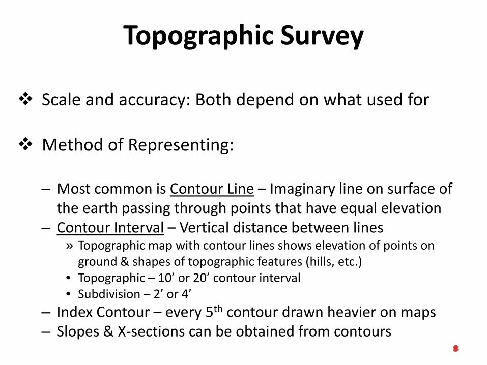
Scale and accuracy: Both depend on what used for
Method of Representing:
– Most common is Contour Line – Imaginary line on surface of the earth passing through points that have equal elevation
– Contour Interval – Vertical distance between lines» Topographic map with contour lines shows elevation of points on
ground & shapes of topographic features (hills, etc.)• Topographic – 10’ or 20’ contour interval• Subdivision – 2’ or 4’
– Index Contour – every 5th contour drawn heavier on maps– Slopes & X-sections can be obtained from contours
Topographic Survey
– Interpolating – can find elevation of any point or find contour line with known elevation of point
– Contour lines that close represent either a hill or depression and can be represented as:
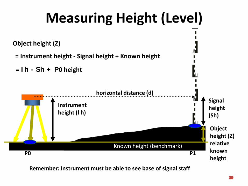
Measuring Height (Level)
Objekt
Instrumentheight (Ih)
Signal height(Sh)
Object height (Z)
= Instrument height - Signal height + Known height
Object height (Z)relative known height
Known height (benchmark)
= Ih - Sh + P0 height
P0 P1
horizontal distance (d)
Remember: Instrument must be able to see base of signal staff
Tacheometry
Tacheometry is the method of topographic survey using a special adapted theodolite known as a tacheometer or level instrument
In this survey, heights and distances are determined from the instrument readings alone
This is use when no EDM and the changing operation is exclude from consideration to survey broken terrain, e.g. land cut by ravines, river valleys, over standings crops, etc. where direct linear measurement would be difficult and inaccurate
Tacheometry
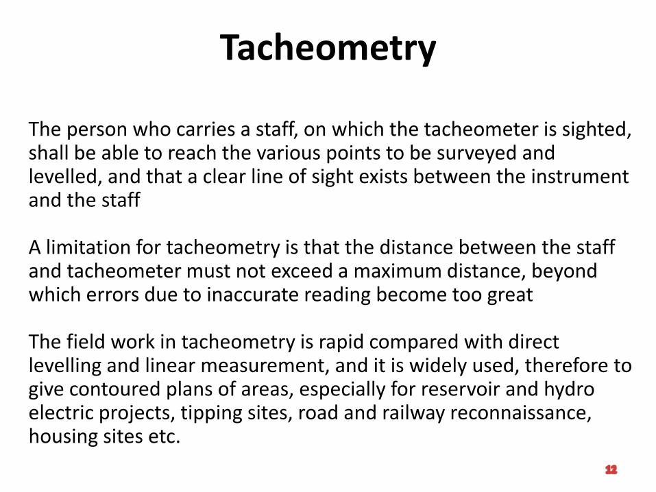
The person who carries a staff, on which the tacheometer is sighted, shall be able to reach the various points to be surveyed and levelled, and that a clear line of sight exists between the instrument and the staff
A limitation for tacheometry is that the distance between the staff and tacheometer must not exceed a maximum distance, beyond which errors due to inaccurate reading become too great
The field work in tacheometry is rapid compared with direct levelling and linear measurement, and it is widely used, therefore to give contoured plans of areas, especially for reservoir and hydro electric projects, tipping sites, road and railway reconnaissance, housing sites etc.
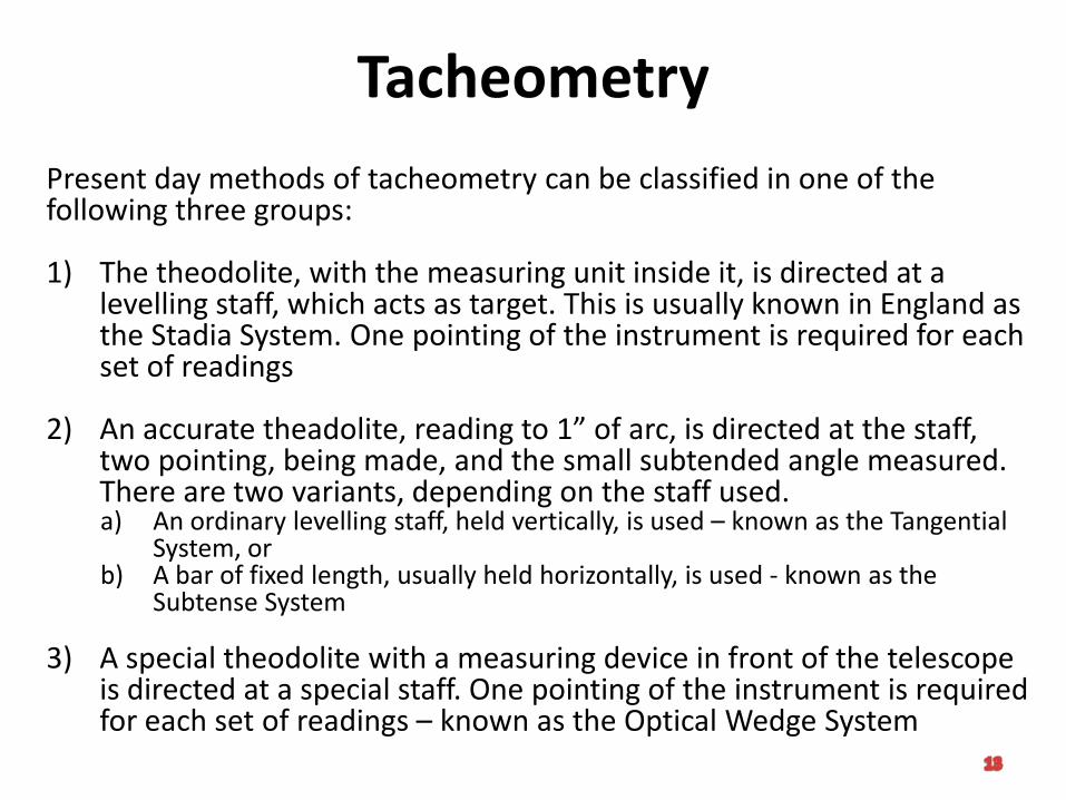
TacheometryPresent day methods of tacheometry can be classified in one of the following three groups:
1) The theodolite, with the measuring unit inside it, is directed at a levelling staff, which acts as target. This is usually known in England as the Stadia System. One pointing of the instrument is required for each set of readings
2) An accurate theadolite, reading to 1” of arc, is directed at the staff, two pointing, being made, and the small subtended angle measured. There are two variants, depending on the staff used.a) An ordinary levelling staff, held vertically, is used – known as the Tangential
System, orb) A bar of fixed length, usually held horizontally, is used - known as the
Subtense System
3) A special theodolite with a measuring device in front of the telescope is directed at a special staff. One pointing of the instrument is required for each set of readings – known as the Optical Wedge System
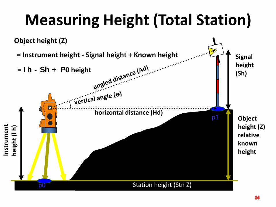
Measuring Height (Total Station)In
stru
men
the
ight
(Ih)
Signal height(Sh)
Object height (Z)relative known height
Station height (Stn Z)p0
p1horizontal distance (Hd)
Object height (Z)
= Instrument height - Signal height + Known height
= Ih - Sh + P0 height
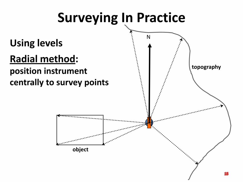
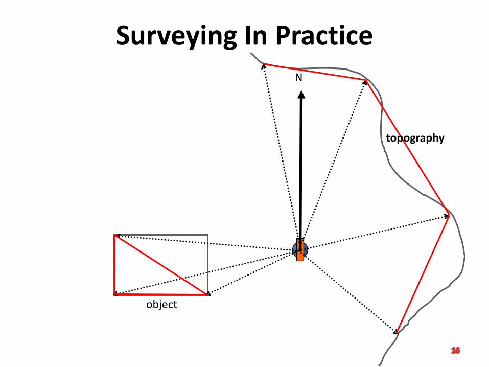
Surveying In Practice
Using levels
Radial method:position instrument centrally to survey points
N
object
topography
Surveying In PracticeN
object
topography
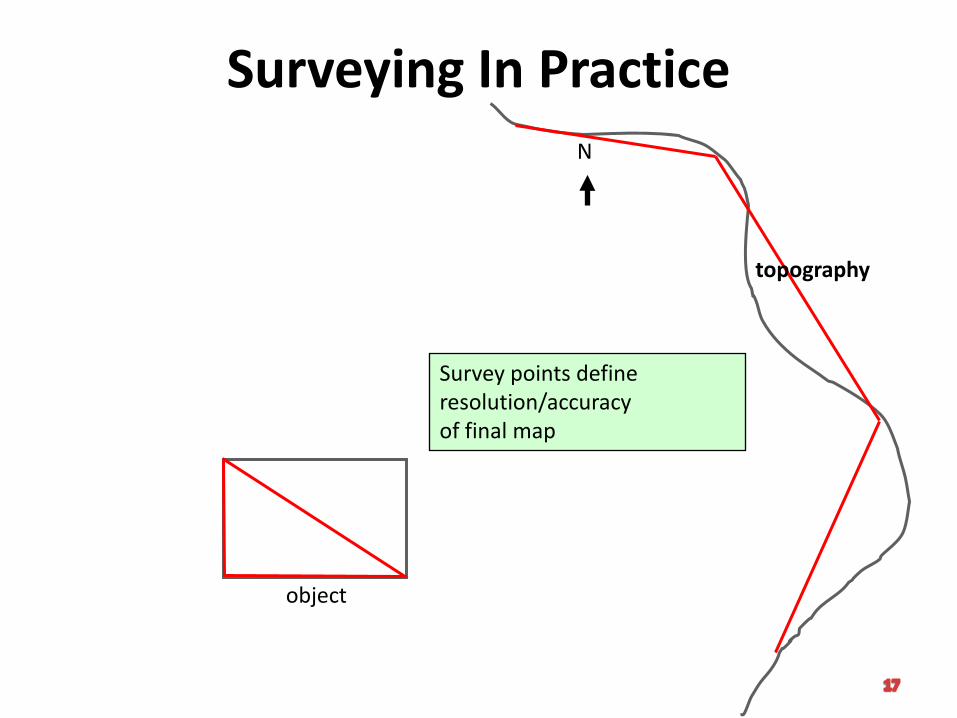
Surveying In PracticeN
object
topography
Survey points defineresolution/accuracyof final map
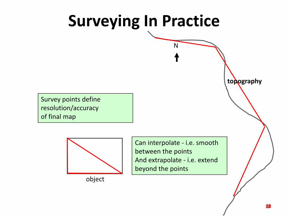
Surveying In PracticeN
object
topography
Survey points defineresolution/accuracyof final map
Can interpolate - i.e. smooth between the pointsAnd extrapolate - i.e. extend beyond the points
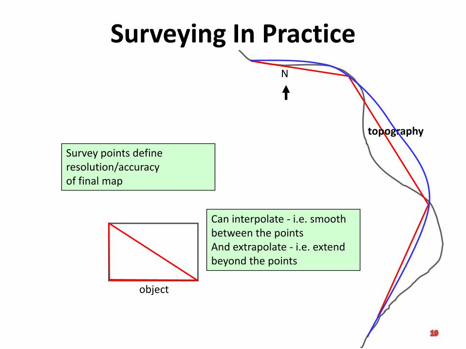
Surveying In PracticeN
object
topography
Survey points defineresolution/accuracyof final map
Can interpolate - i.e. smooth between the pointsAnd extrapolate - i.e. extend beyond the points
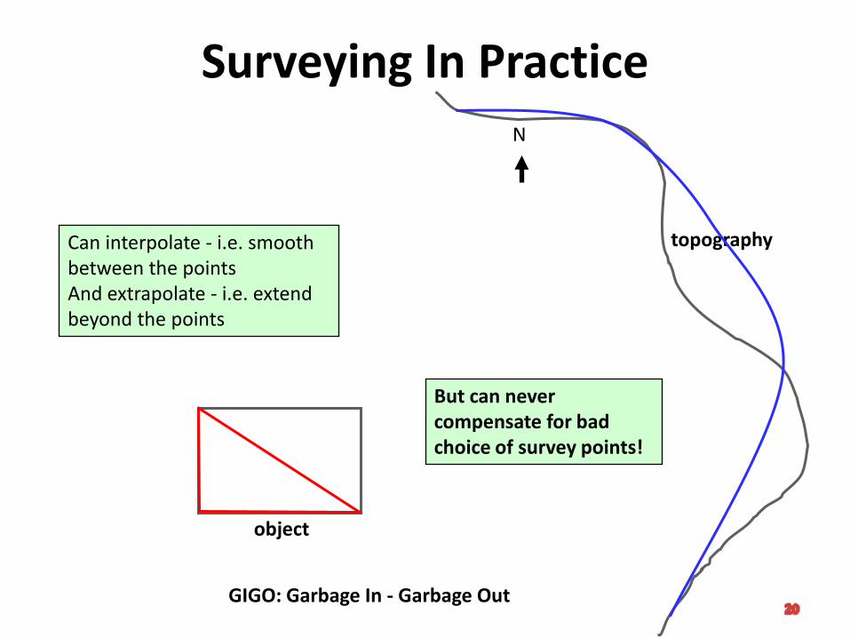
Surveying In PracticeN
object
topographyCan interpolate - i.e. smooth between the pointsAnd extrapolate - i.e. extend beyond the points
But can never compensate for bad choice of survey points!
GIGO: Garbage In - Garbage Out
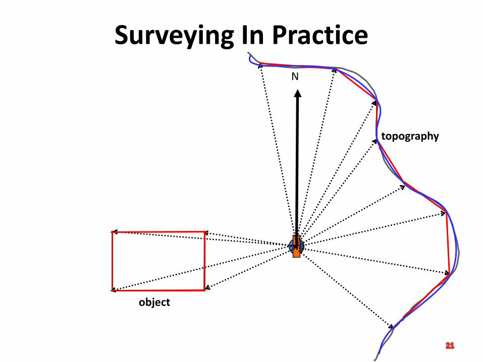
Surveying In PracticeN
object
topography
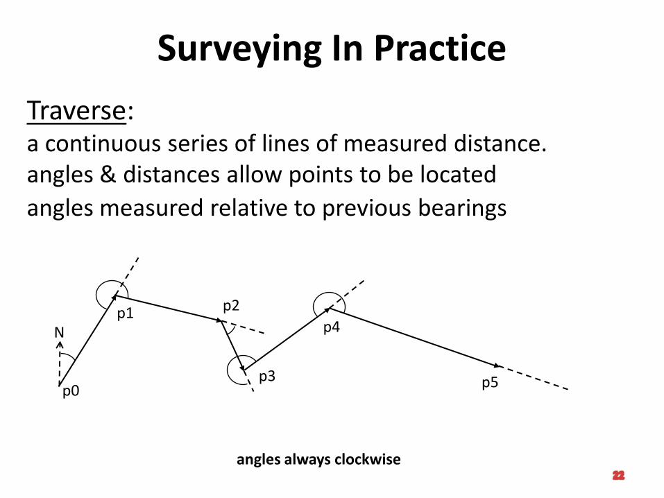
Surveying In Practice
Traverse:a continuous series of lines of measured distance.angles & distances allow points to be located
p0
N
angles measured relative to previous bearings
angles always clockwise
p1 p2
p3
p4
p5
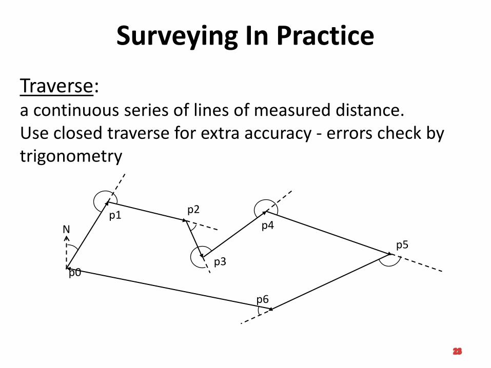
Surveying In Practice
Traverse:a continuous series of lines of measured distance.Use closed traverse for extra accuracy - errors check by trigonometry
p0
Np1 p2
p3
p4
p5
p6
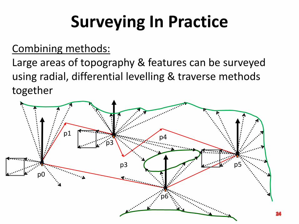
Surveying In PracticeCombining methods:Large areas of topography & features can be surveyed using radial, differential levelling & traverse methods together
p1
p3
p4
p5
p6
p3
p0
Contour & Contour Line
A contour is an imaginary line of constant elevation on the ground surface. It
may be thought of as the trace formed by the intersection of a level surface with
the ground surface, for example, the shore line of a still body of water
If on a drawing are plotted the locations of several ground points of equal
elevation, say, 720 ft. above sea level, a line on the map joining these points is
called a contour line. Thus, contours on the ground are represented by contour
lines on the map. Loosely, however, the terms contour and contour line are often
used interchangeably. On a given map, successive contour lines represent
elevations differing by a fixed vertical distance called the contour interval
The use of contour lines has the great advantage that it permits the
representation of relief with much greater facility, and with far greater
definiteness and accuracy, than do other symbols. It has the disadvantage that
the map is not so legible to the layman
Characteristics of Contours
1. Each contour must close upon itself with within a map or outside its borders – a contour line cannot end on a map except at the edge
2. Contours do not cross or meet except in caves, cliffs & vertical walls where they can meet
3. Contour lines crossing streams form V’s pointing upstream
4. Contour lines crossing a ridge form U’s pointing down the ridge
5. Contour lines tend to parallel streams
Characteristics of Contours
6. Contour lines are uniformly spaced on uniform slopes
7. Horizontal spacing between contour lines indicated steepness of slope on ground
8. Contours are generally perpendicular to direction of maximum slope
9. Contours can never branch into 2 contours of the same elevation
Contour Map Construction
Normally the construction of a topographic map consists of three operations:
The plotting of the horizontal control, or skeleton upon which the details of the map are hung
The plotting of details, including the map location of points of known ground elevation, called ground points, by means of which the relief is to be indicated
The construction of contour lines at a given contour interval, the ground points being employed as guides in the proper location of the contour lines. A ground point on a contour is called a contour point
Cross Section
Cross sectioning consists in making measurements to define vertical sections of the ground surface at right-angles to the centre line. It is usually done with a level or hand level and a cloth tape
Unlike slope staking, which stops at the limits of the earth work, cross sectioning is carried out as far as appears necessary or desirable to insure coverage of the construction line. Elevations are obtained at all breaks in the ground surface, and perhaps at multiples of specified distances such as 25, 50 or 100 ft., or at every contour interval. Other features, such as fence lines, are also located by their distances out from the centre line
Suitable grades can be fitted to the plotted cross sections in the office. The station spacing of slope stakes and cross sections depends upon the type of terrain, accuracy required, and other factors, but 100 ft. stations are the maximum
Field Methods of Topographic Survey
Factors that influence method:
1. Scale of map2. Contour interval3. Type of terrain4. Nature of project5. Equipment available6. Required accuracy7. Existing control8. Extent of area to be mapped
Field Methods of Topographic Survey
Methods:
1. Cross section – railroad of highway
2. Trace contour – drainage or impoundments
3. Grid – small areas
4. Controlling point – large area, plane table
5. Theodolite & EDM - radial
Field Methods of Topographic Survey
Cross Section Method (Plus Offset):
Equipment used: Transit, tape, and level
1. Establish horizontal control – traverse between control points – stakes set at cross section intervals
2. Run profile of traverse line
3. Take cross section
4. Locate planimetric features from traverse line
Field Methods of Topographic Survey
Trace Contour:
1. Contour is by traverse
2. Establish elevation of each station
3. Contour elevation established and is then followed by rod person
4. Contour elevation is marked, then tied to traverse line by plus-offset:• Most accurate and expensive work
• Elevation of reservoir water line
• 2 transit use
Field Methods of Topographic Survey
Grid Method:
1. Establish baselines
2. Estimate grid of uniform size – smaller grid = more accurate
3. Number grid
4. Shoot elevation at each point
5. Tie existing objects to grid points
Field Methods of Topographic Survey
Controlling Point Method (old and sketched in field):
1. Determine position & elevation of pre-selected control points
2. Depends greatly on experience & judgment of people doing work
3. Required traverse of area (CP’s)
4. Locations are made & elevations obtained along control points – then intermittent topographic sketched in
Field Methods of Topographic Survey
Theodolite & EDM (Radial) and later total station:
Replaces tacheometry (stadia)
1. Establish control points (horizontal and elevation)
2. Shoot locations and turn vertical angles
3. Used for large areas
Field Methods of Topographic Survey
Common mistakes in topographic surveys:
1. Improper selection of contour interval
2. Unsatisfactory equipment or field method for the particular survey and terrain conditions
3. Insufficient horizontal and vertical control of suitable precision
4. Omission of some topographic details
Question
1) Explain the use of topographic survey in current survey practice
1) Explain what are tacheometry and the three methods used in tacheometry

T h a n k Yo u &
Q u e s t i o n a n d A n s w e r
39