Embed Size (px)
Citation preview
Sept. 11, 2001 - CUHK 1
Engineering Wireless Multimedia Engineering Wireless Multimedia Networks for Networks for QoS QoS DifferentiationDifferentiation
Dr. Mooi Choo Chuah ([email protected])Dr. On-Ching Yue ([email protected])Bell Laboratories, Lucent Technologies
Sept. 11, 2001 - CUHK 2
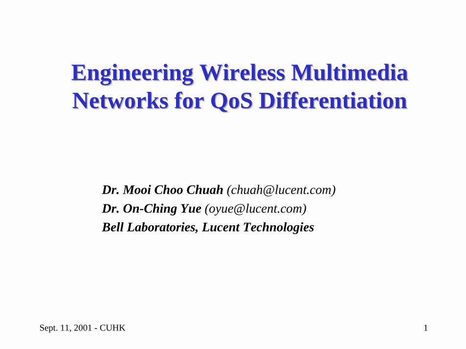
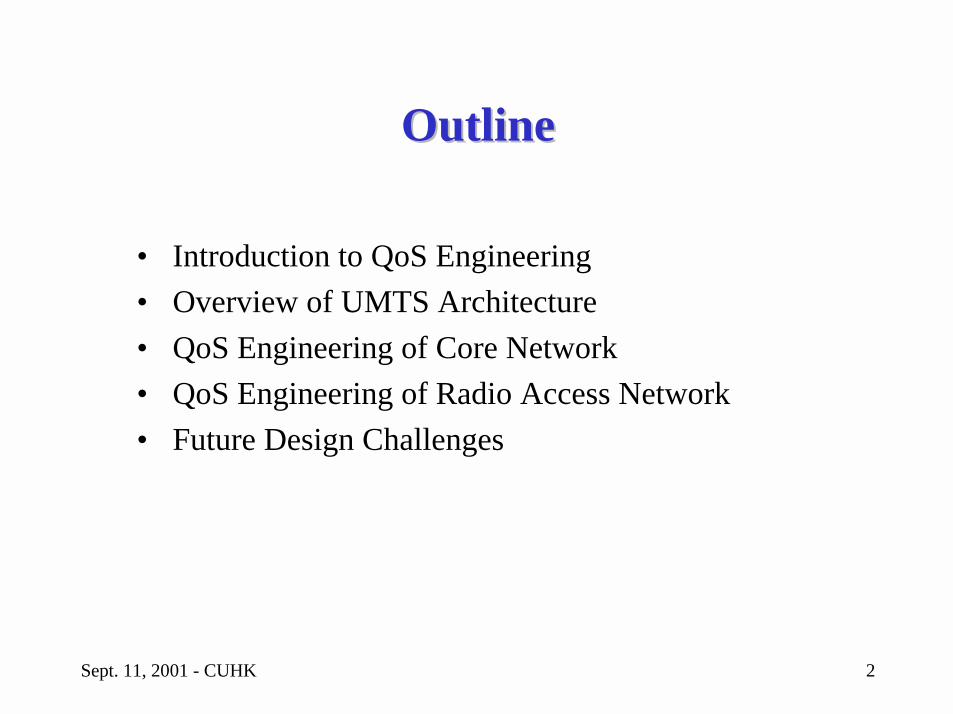
OutlineOutline
• Introduction to QoS Engineering• Overview of UMTS Architecture• QoS Engineering of Core Network• QoS Engineering of Radio Access Network• Future Design Challenges
Sept. 11, 2001 - CUHK 3
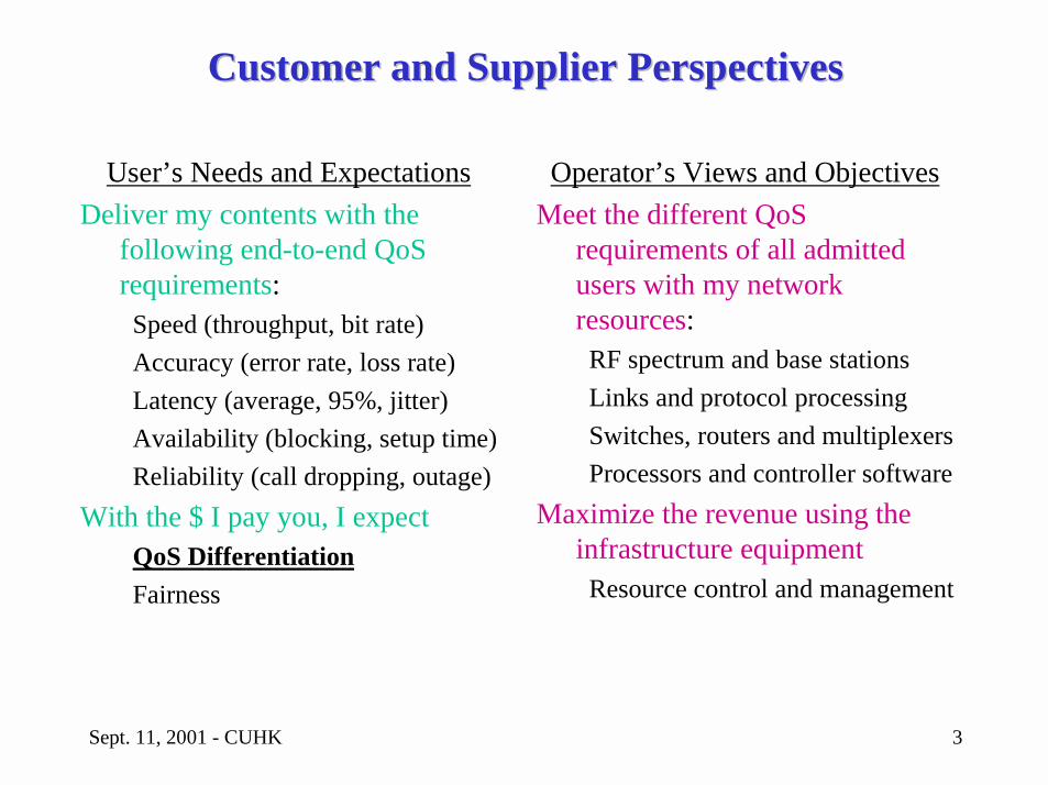
Customer and Supplier PerspectivesCustomer and Supplier Perspectives
User’s Needs and ExpectationsDeliver my contents with the
following end-to-end QoSrequirements:
Speed (throughput, bit rate)Accuracy (error rate, loss rate)Latency (average, 95%, jitter)Availability (blocking, setup time)Reliability (call dropping, outage)
With the $ I pay you, I expectQoS DifferentiationFairness
Operator’s Views and ObjectivesMeet the different QoS
requirements of all admitted users with my network resources:
RF spectrum and base stationsLinks and protocol processingSwitches, routers and multiplexersProcessors and controller software
Maximize the revenue using the infrastructure equipment
Resource control and management
Sept. 11, 2001 - CUHK 4
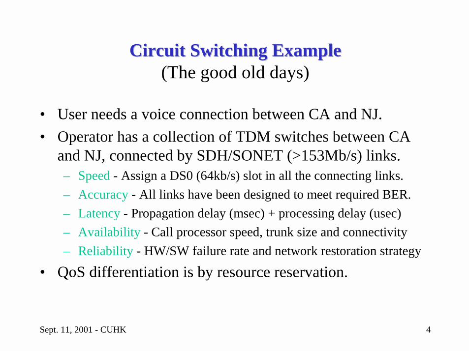
Circuit Switching ExampleCircuit Switching Example(The good old days)
• User needs a voice connection between CA and NJ.• Operator has a collection of TDM switches between CA
and NJ, connected by SDH/SONET (>153Mb/s) links.– Speed - Assign a DS0 (64kb/s) slot in all the connecting links.– Accuracy - All links have been designed to meet required BER.– Latency - Propagation delay (msec) + processing delay (usec)– Availability - Call processor speed, trunk size and connectivity– Reliability - HW/SW failure rate and network restoration strategy
• QoS differentiation is by resource reservation.
Sept. 11, 2001 - CUHK 5
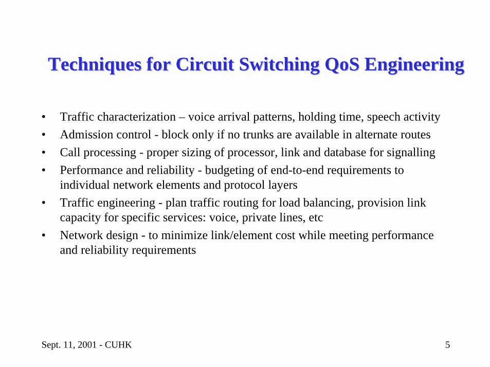
Techniques for Circuit SwitchingTechniques for Circuit Switching QoSQoS EngineeringEngineering
• Traffic characterization – voice arrival patterns, holding time, speech activity• Admission control - block only if no trunks are available in alternate routes• Call processing - proper sizing of processor, link and database for signalling• Performance and reliability - budgeting of end-to-end requirements to
individual network elements and protocol layers • Traffic engineering - plan traffic routing for load balancing, provision link
capacity for specific services: voice, private lines, etc• Network design - to minimize link/element cost while meeting performance
and reliability requirements
Sept. 11, 2001 - CUHK 6
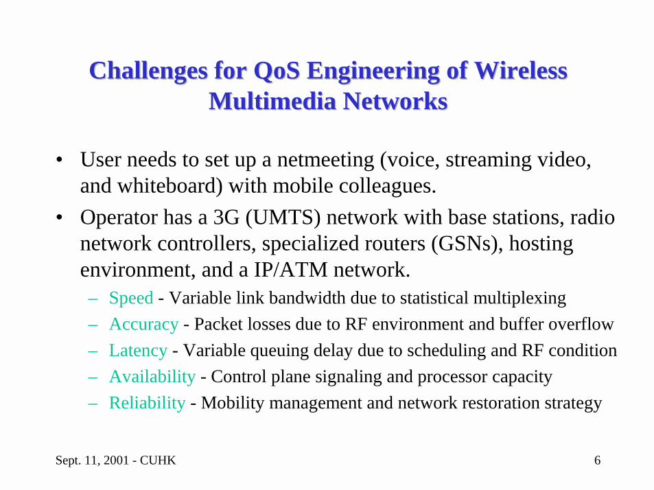
Challenges for Challenges for QoS QoS Engineering of Wireless Engineering of Wireless Multimedia NetworksMultimedia Networks
• User needs to set up a netmeeting (voice, streaming video, and whiteboard) with mobile colleagues.
• Operator has a 3G (UMTS) network with base stations, radio network controllers, specialized routers (GSNs), hosting environment, and a IP/ATM network.– Speed - Variable link bandwidth due to statistical multiplexing– Accuracy - Packet losses due to RF environment and buffer overflow– Latency - Variable queuing delay due to scheduling and RF condition– Availability - Control plane signaling and processor capacity– Reliability - Mobility management and network restoration strategy
Sept. 11, 2001 - CUHK 7
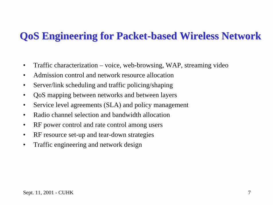
QoSQoS Engineering for PacketEngineering for Packet--based Wireless Networkbased Wireless Network
• Traffic characterization – voice, web-browsing, WAP, streaming video• Admission control and network resource allocation• Server/link scheduling and traffic policing/shaping• QoS mapping between networks and between layers• Service level agreements (SLA) and policy management• Radio channel selection and bandwidth allocation• RF power control and rate control among users• RF resource set-up and tear-down strategies• Traffic engineering and network design
Sept. 11, 2001 - CUHK 8
OutlineOutline
• Introduction to QoS Engineering• Overview of UMTS Architecture• QoS Engineering of Core Network• QoS Engineering of Radio Access Network• Future Design Challenges
Sept. 11, 2001 - CUHK 9
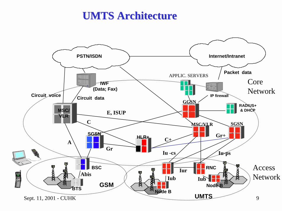
UMTS ArchitectureUMTS Architecture
BTS
MSC/VLR
Circuit voice
IWF (Data; Fax)
Circuit data
GSM
A
Abis
E, ISUP
C
PSTN/ISDN
Core Network
BSC
HLR+
APPLIC. SERVERS
Internet/Intranet
IP firewall
Packet data
RADIUS+& DHCP
GGSN
Gr
SGSN
UMTSNode B
Node B
RNC
MSC/VLR
IurIub
Access Network
Iu -cs
C+
Iub
SGSN
Iu-ps
Gr+
Sept. 11, 2001 - CUHK 10
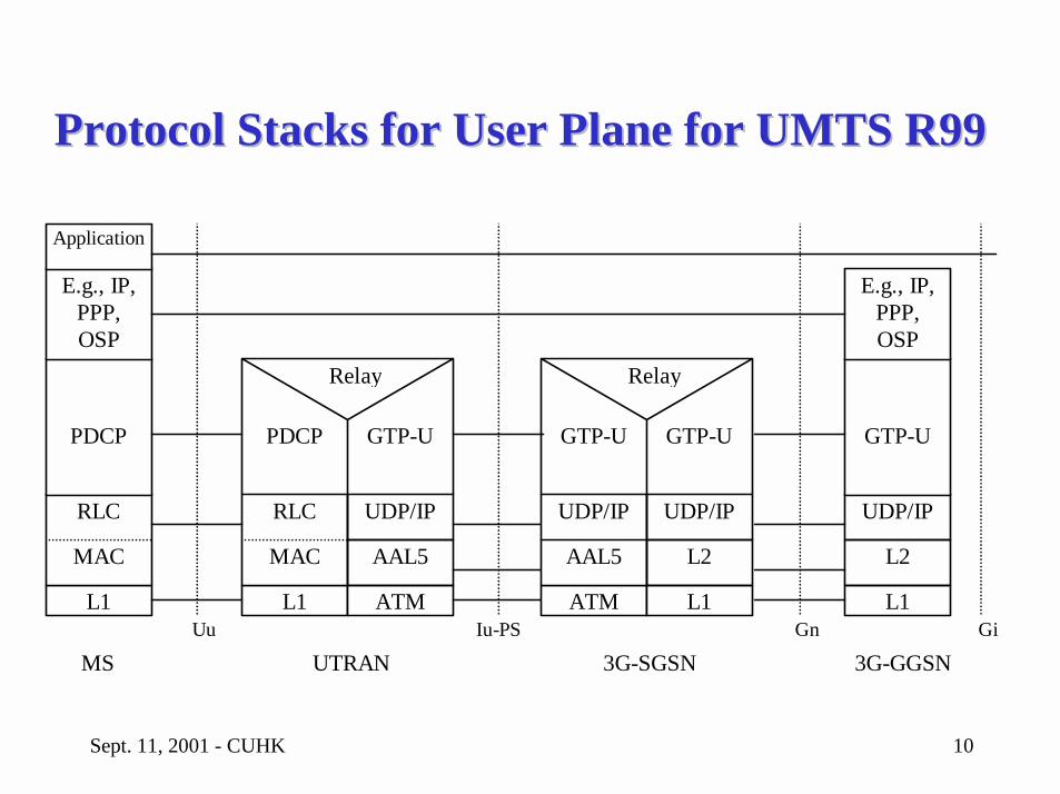
Protocol Stacks for User Plane for UMTS R99Protocol Stacks for User Plane for UMTS R99
L1
RLC
PDCP
MAC
E.g., IP,PPP,OSP
Application
L1
RLC
PDCP
MAC
ATM
UDP/IP
GTP-U
AAL5
Relay
L1
UDP/IP
L2
GTP-U
E.g., IP,PPP,OSP
3G-SGSNUTRANMSIu-PSUu Gn Gi
3G-GGSN
ATM
UDP/IP
GTP-U
AAL5
L1
UDP/IP
GTP-U
L2
Relay
Sept. 11, 2001 - CUHK 11
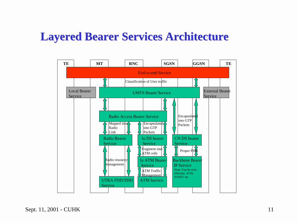
Layered Bearer Services ArchitectureLayered Bearer Services Architecture
TE MT RNC SGSN GGSN TE
End-to-end Service
UMTS Bearer Service
Radio Access Bearer Service
Radio Bearer Service
Iu DS bearer Service
CN DS bearerService
UTRA FDD/TDD Service
Iu ATM Bearer Service
Backbone Bearer IP Service Note: Can be over Ethernet, ATM, SONET etc.
ATM Service
Local BearerService
External Bearer Service
Classification of User traffic
Encapsulatedinto GTPPacketsEncapsulated
into GTPPackets
Fragment intoATM cells
Mapped intoRadioLink
ATM TrafficManagement
Proper PHB
Radio resourcemanagement
Sept. 11, 2001 - CUHK 12
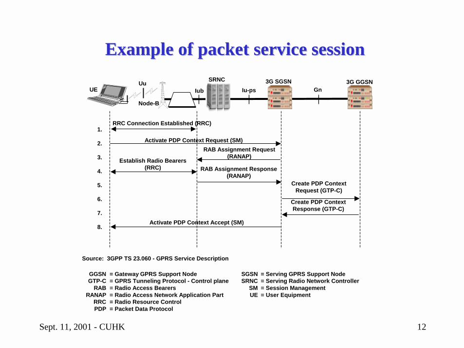
Example of packet service sessionExample of packet service session
UE Iub
SRNC 3G SGSN 3G GGSNIu-ps Gn
RRC Connection Established (RRC)
Activate PDP Context Request (SM)
Establish Radio Bearers(RRC)
RAB Assignment Request(RANAP)
RAB Assignment Response(RANAP)
Create PDP ContextRequest (GTP-C)
Create PDP ContextResponse (GTP-C)
Activate PDP Context Accept (SM)
1.
2.
3.
4.
5.
6.
7.
8.
Node-B
Uu
SGSNSRNC
SMUE
= Serving GPRS Support Node= Serving Radio Network Controller= Session Management= User Equipment
Source: 3GPP TS 23.060 - GPRS Service Description
GGSNGTP-C
RABRANAP
RRCPDP
= Gateway GPRS Support Node= GPRS Tunneling Protocol - Control plane= Radio Access Bearers= Radio Access Network Application Part= Radio Resource Control= Packet Data Protocol
Sept. 11, 2001 - CUHK 13
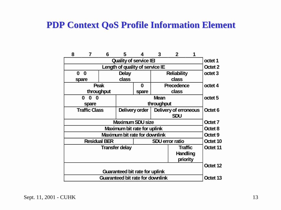
PDP ContextPDP Context QoSQoS Profile Information ElementProfile Information Element
8 7 6 5 4 3 2 1Quality of service IEI octet 1
Length of quality of service IE Octet 20 0spare
Delayclass
Reliabilityclass
octet 3
Peakthroughput
0spare
Precedenceclass
octet 4
0 0 0spare
Meanthroughput
octet 5
Traffic Class Delivery order Delivery of erroneousSDU
Octet 6
Maximum SDU size Octet 7Maximum bit rate for uplink Octet 8
Maximum bit rate for downlink Octet 9Residual BER SDU error ratio Octet 10
Transfer delay TrafficHandlingpriority
Octet 11
Guaranteed bit rate for uplinkOctet 12
Guaranteed bit rate for downlink Octet 13
Sept. 11, 2001 - CUHK 14
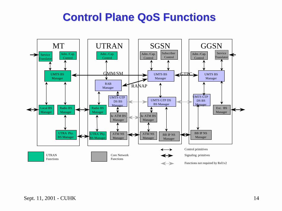
ServiceTranslator
UMTS BSManager
Adm./Cap.Control
Local BSManager
Radio BSManager
UTRA Phy.BS Manager
MT
RABManager
Adm./Cap.Control
Iu ATM BSManager
Radio BSManager
ATM NSManager
UTRAN
UTRA Phy.BS Manager
UMTS BSManager
Adm./Cap.Control
Ext. BSManager
GGSNSubscriber
Control
UMTS BSManager
Adm./Cap.Control
UMTS GTP DS BS Manager
BB IP NSManager
SGSNService
Translator
Iu ATM BSManager
ATM NSManager
BB IP NSManager
UMTS GTP DS BS
Manager
GTPCGMM/SM
RANAP
UMTS GTPDS BS
Manager
UTRANFunctions
Core NetworkFunctions
Functions not required by Rel1v2
Control primitives
Signaling primitves
Control Plane Control Plane QoS QoS FunctionsFunctions
Sept. 11, 2001 - CUHK 15
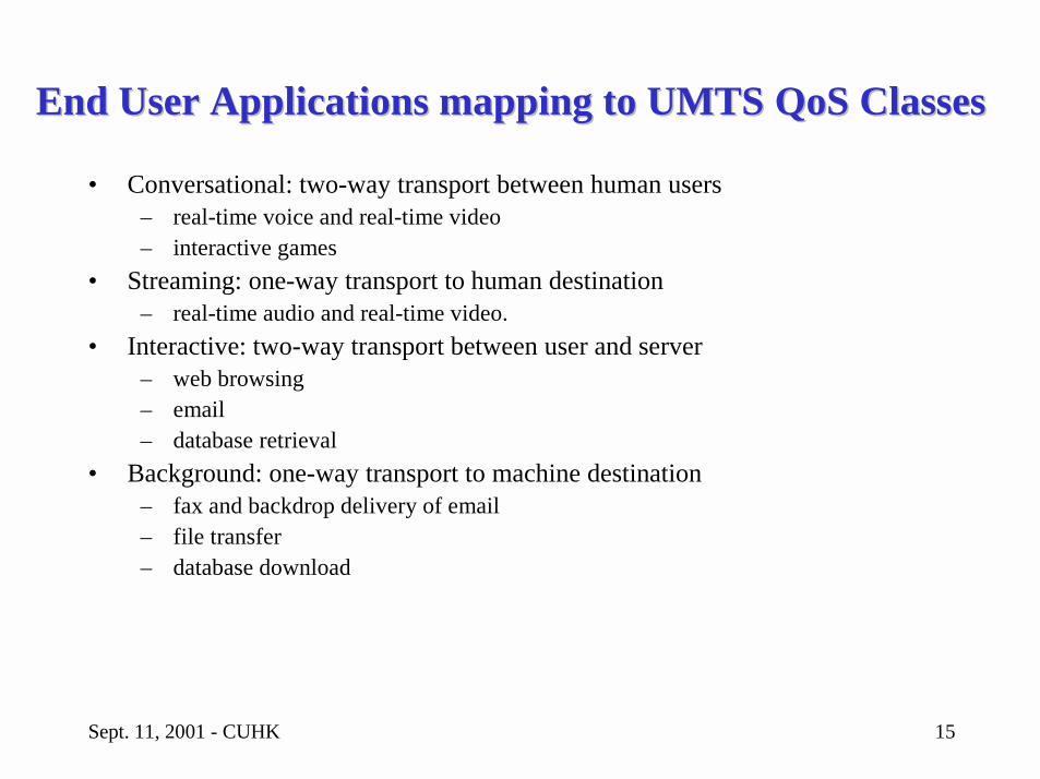
End User Applications mapping to UMTSEnd User Applications mapping to UMTS QoSQoS ClassesClasses
• Conversational: two-way transport between human users– real-time voice and real-time video– interactive games
• Streaming: one-way transport to human destination– real-time audio and real-time video.
• Interactive: two-way transport between user and server– web browsing– email– database retrieval
• Background: one-way transport to machine destination– fax and backdrop delivery of email– file transfer– database download
Sept. 11, 2001 - CUHK 16
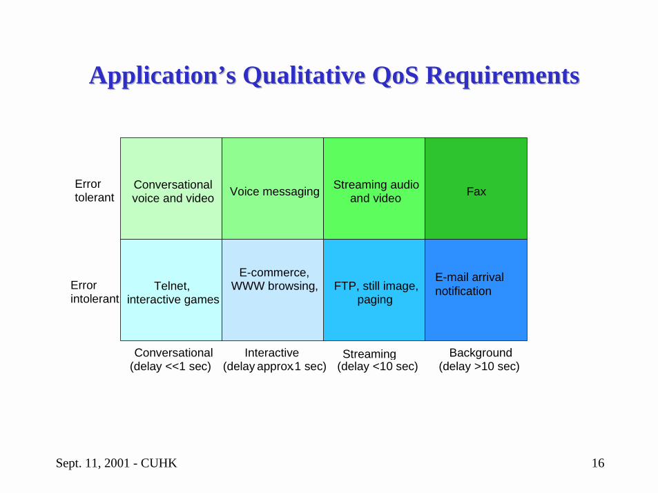
Application’s Qualitative Application’s Qualitative QoSQoS RequirementsRequirements
Errortolerant
Errorintolerant
Conversational(delay <<1 sec)
Interactive(delay approx.1 sec)
Streaming(delay <10 sec)
Background(delay >10 sec)
Conversationalvoice and video Voice messaging Streaming audio
and video Fax
E-mail arrivalnotificationFTP, still image,
paging
E-commerce,WWW browsing,Telnet,
interactive games
Sept. 11, 2001 - CUHK 17
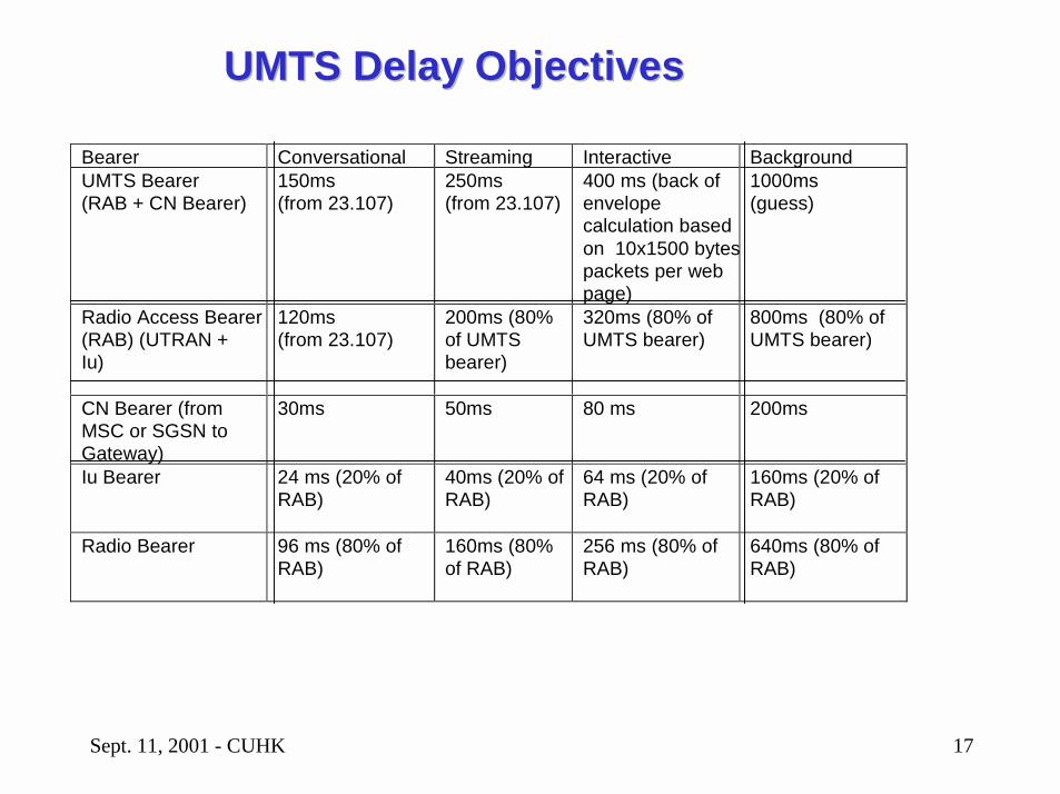
Bearer Conversational Streaming Interactive BackgroundUMTS Bearer(RAB + CN Bearer)
150ms(from 23.107)
250ms(from 23.107)
400 ms (back ofenvelopecalculation basedon 10x1500 bytespackets per webpage)
1000ms(guess)
Radio Access Bearer(RAB) (UTRAN +Iu)
120ms(from 23.107)
200ms (80%of UMTSbearer)
320ms (80% ofUMTS bearer)
800ms (80% ofUMTS bearer)
CN Bearer (fromMSC or SGSN toGateway)
30ms 50ms 80 ms 200ms
Iu Bearer 24 ms (20% ofRAB)
40ms (20% ofRAB)
64 ms (20% ofRAB)
160ms (20% ofRAB)
Radio Bearer 96 ms (80% ofRAB)
160ms (80%of RAB)
256 ms (80% ofRAB)
640ms (80% ofRAB)
UMTS Delay ObjectivesUMTS Delay Objectives
Sept. 11, 2001 - CUHK 18
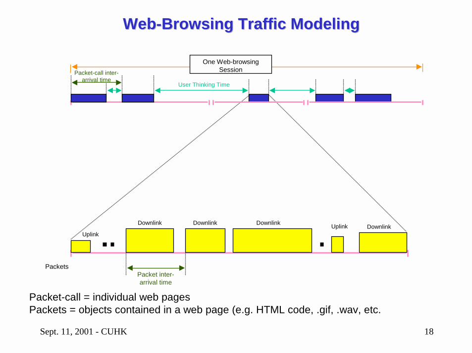
Packets
One Web-browsing SessionPacket-call inter-
arrival timeUser Thinking Time
Packet inter-arrival time
Uplink
Downlink UplinkDownlink Downlink Downlink
Packet-call = individual web pagesPackets = objects contained in a web page (e.g. HTML code, .gif, .wav, etc.
WebWeb--Browsing Traffic ModelingBrowsing Traffic Modeling
Sept. 11, 2001 - CUHK 19
OutlineOutline
• Introduction to QoS Engineering• Overview of UMTS Architecture• QoS Engineering of Core Network• QoS Engineering of Radio Access Network• Future Design Challenges

Sept. 11, 2001 - CUHK 20
ServiceTranslator
UMTS BSManager
Adm./Cap.Control
Local BSManager
Radio BSManager
UTRA Phy.BS Manager
MT
RABManager
Adm./Cap.Control
Iu ATM BSManager
Radio BSManager
ATM NSManager
UTRAN
UTRA Phy.BS Manager
UMTS BSManager
Adm./Cap.Control
Ext. BSManager
GGSNSubscriber
Control
UMTS BSManager
Adm./Cap.Control
UMTS GTP DS BS Manager
BB IP NSManager
SGSNService
Translator
Iu ATM BSManager
ATM NSManager
BB IP NSManager
UMTS GTP DS BS
Manager
GTPCGMM/SM
RANAP
UMTS GTPDS BS
Manager
UTRANFunctions
Core NetworkFunctions
Functions not required by Rel1v2
Control primitives
Signaling primitves
SGSN is the Brain in the Core NetworkSGSN is the Brain in the Core Network
Sept. 11, 2001 - CUHK 21
SGSN is the Brain in the Core NetworkSGSN is the Brain in the Core Network
• It receives the connection setup request with the QoS requirement.
• It instructs the RNC to set up the Radio Bearer• It sets up a GTP connection between GGSN and the RNC• QoS engineering of the GTP tunnels
– Throughput– Latency– Loss– Availability
Sept. 11, 2001 - CUHK 22
GPRS GTP TunnelsGPRS GTP Tunnels
• GPRS defines GTP in 3GPP TS 29.060• GPRS transports TCP/IP or UDP/IP packets within UDP/IP packets
through the GPRS network• GPRS allows layer 2 PPP frames to be transported transparently by
encapsulating PPP frames within UDP/IP packet.• A GTP tunnel in the user plane is defined for each PDP context in the
GSNs and/or each RAB in the RNC.• A GTP tunnel in the control plane is defined for all PDP contexts with
the same PDP address and APN.
Sept. 11, 2001 - CUHK 23
GPRS Tunnel Protocol (GTP)GPRS Tunnel Protocol (GTP)
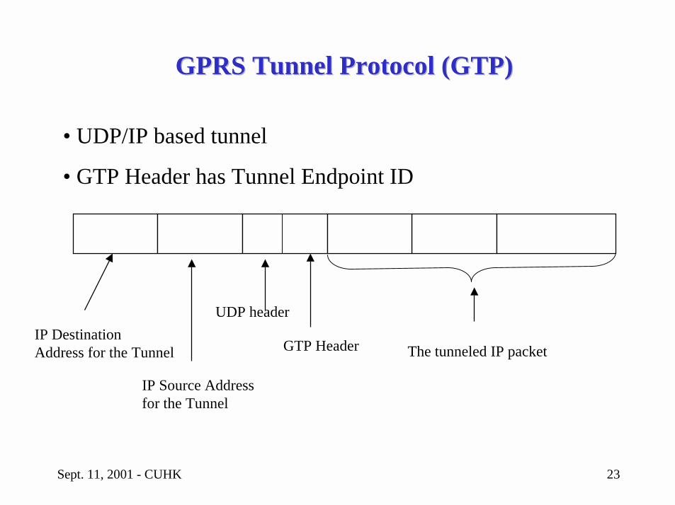
IP DestinationAddress for the Tunnel
IP Source Address for the Tunnel
GTP Header The tunneled IP packet
• UDP/IP based tunnel
• GTP Header has Tunnel Endpoint ID
UDP header
Sept. 11, 2001 - CUHK 24
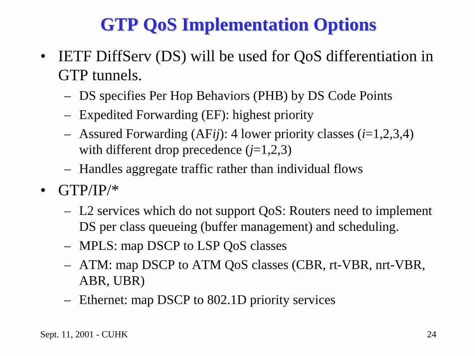
GTP GTP QoS QoS Implementation OptionsImplementation Options• IETF DiffServ (DS) will be used for QoS differentiation in
GTP tunnels.– DS specifies Per Hop Behaviors (PHB) by DS Code Points– Expedited Forwarding (EF): highest priority– Assured Forwarding (AFij): 4 lower priority classes (i=1,2,3,4)
with different drop precedence (j=1,2,3)– Handles aggregate traffic rather than individual flows
• GTP/IP/*– L2 services which do not support QoS: Routers need to implement
DS per class queueing (buffer management) and scheduling.– MPLS: map DSCP to LSP QoS classes – ATM: map DSCP to ATM QoS classes (CBR, rt-VBR, nrt-VBR,
ABR, UBR)– Ethernet: map DSCP to 802.1D priority services
Sept. 11, 2001 - CUHK 25
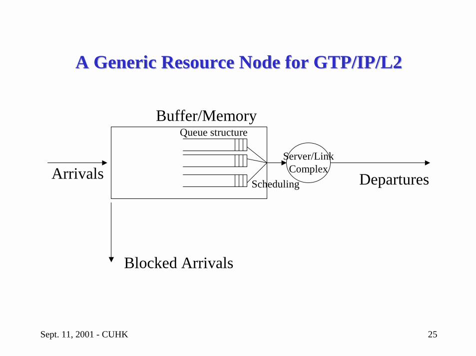
A Generic Resource Node for GTP/IP/L2A Generic Resource Node for GTP/IP/L2
Arrivals
Buffer/Memory
Departures
Queue structure
Scheduling
Server/LinkComplex
Blocked Arrivals
Sept. 11, 2001 - CUHK 26
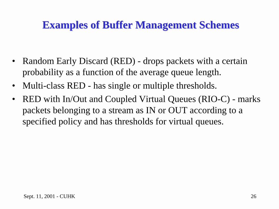
Examples of Buffer Management SchemesExamples of Buffer Management Schemes
• Random Early Discard (RED) - drops packets with a certain probability as a function of the average queue length.
• Multi-class RED - has single or multiple thresholds.• RED with In/Out and Coupled Virtual Queues (RIO-C) - marks
packets belonging to a stream as IN or OUT according to a specified policy and has thresholds for virtual queues.
Sept. 11, 2001 - CUHK 27
Scheduler DesignScheduler Design
• Examples– Weighted Round Robin: Classical, List-based and Multiclass.– Weighted Fair Queueing: GPS, SCFQ, WF2Q– Earliest Due Date– Class-based Queueing
• Design Considerations– Worst case fairness– Fair Excess bandwidth sharing– Scalable – in terms of latency with increasing number of sessions– Implementation complexity
Sept. 11, 2001 - CUHK 28
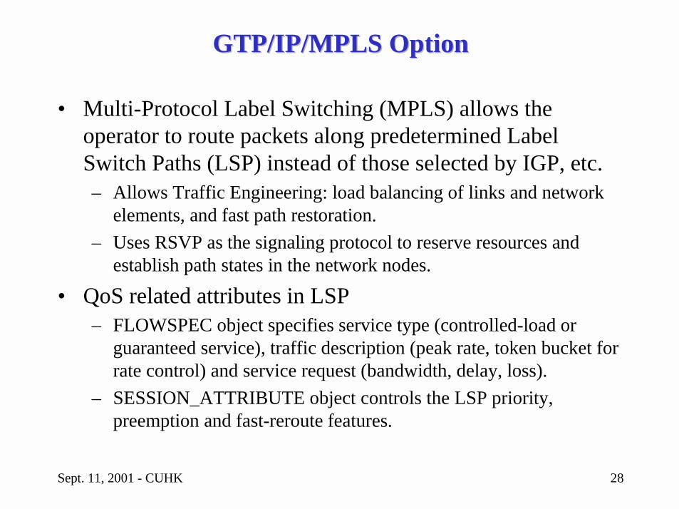
GTP/IP/MPLS OptionGTP/IP/MPLS Option
• Multi-Protocol Label Switching (MPLS) allows the operator to route packets along predetermined Label Switch Paths (LSP) instead of those selected by IGP, etc.– Allows Traffic Engineering: load balancing of links and network
elements, and fast path restoration.– Uses RSVP as the signaling protocol to reserve resources and
establish path states in the network nodes.
• QoS related attributes in LSP– FLOWSPEC object specifies service type (controlled-load or
guaranteed service), traffic description (peak rate, token bucket for rate control) and service request (bandwidth, delay, loss).
– SESSION_ATTRIBUTE object controls the LSP priority, preemption and fast-reroute features.
Sept. 11, 2001 - CUHK 29
OutlineOutline
• Introduction to QoS Engineering• Overview of UMTS Architecture• QoS Engineering of Core Network• QoS Engineering of Radio Access Network• Future Design Challenges
Sept. 11, 2001 - CUHK 30
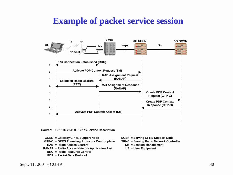
Example of packet service sessionExample of packet service session
UE Iub
SRNC 3G SGSN 3G GGSNIu-ps Gn
RRC Connection Established (RRC)
Activate PDP Context Request (SM)
Establish Radio Bearers(RRC)
RAB Assignment Request(RANAP)
RAB Assignment Response(RANAP)
Create PDP ContextRequest (GTP-C)
Create PDP ContextResponse (GTP-C)
Activate PDP Context Accept (SM)
1.
2.
3.
4.
5.
6.
7.
8.
Node-B
Uu
SGSNSRNC
SMUE
= Serving GPRS Support Node= Serving Radio Network Controller= Session Management= User Equipment
Source: 3GPP TS 23.060 - GPRS Service Description
GGSNGTP-C
RABRANAP
RRCPDP
= Gateway GPRS Support Node= GPRS Tunneling Protocol - Control plane= Radio Access Bearers= Radio Access Network Application Part= Radio Resource Control= Packet Data Protocol
Sept. 11, 2001 - CUHK 31
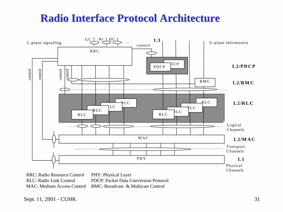
Radio Interface Protocol ArchitectureRadio Interface Protocol Architecture
PhysicalC hannels
L 3
cont
rol
cont
rol
cont
rol
cont
rol
LogicalC hannels
T ransportC hannels
C -p lane signalling U -p lane inform ation
PH Y
L 2/M A C
L 1
R LC
D CN tG C
L 2/R L C
M A C
R L CR LC
R LCR L C
R LCR L C
R LC
B M C L 2/B M C
R R Ccontro l
PD C PP D C P L 2/PD C P
RRC: Radio Resource Control PHY: Physical LayerRLC: Radio Link Control PDCP: Packet Data Conversion ProtocolMAC: Medium Access Control BMC: Broadcast- & Multicast Control
Sept. 11, 2001 - CUHK 32
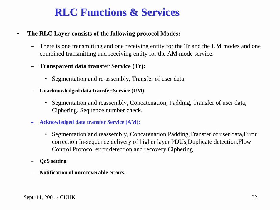
RLC Functions & ServicesRLC Functions & Services
• The RLC Layer consists of the following protocol Modes:
– There is one transmitting and one receiving entity for the Tr and the UM modes and one combined transmitting and receiving entity for the AM mode service.
– Transparent data transfer Service (Tr):
• Segmentation and re-assembly, Transfer of user data.
– Unacknowledged data transfer Service (UM):
• Segmentation and reassembly, Concatenation, Padding, Transfer of user data, Ciphering, Sequence number check.
– Acknowledged data transfer Service (AM):
• Segmentation and reassembly, Concatenation,Padding,Transfer of user data,Error correction,In-sequence delivery of higher layer PDUs,Duplicate detection,Flow Control,Protocol error detection and recovery,Ciphering.
– QoS setting
– Notification of unrecoverable errors.
Sept. 11, 2001 - CUHK 33
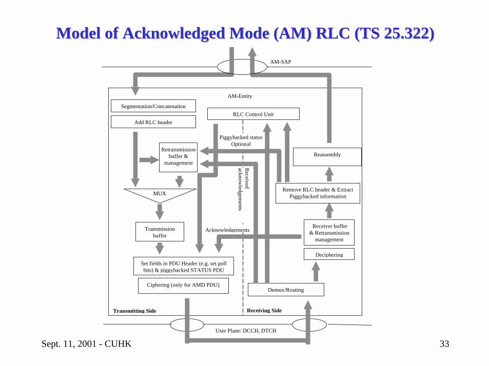
Model of Acknowledged Mode (AM) RLC (TS 25.322)Model of Acknowledged Mode (AM) RLC (TS 25.322)
Transmissionbuffer
Retransmissionbuffer &
management
MUX
Set fields in PDU Header (e.g. set pollbits) & piggybacked STATUS PDU
RLC Control Unit
Received
acknowledgem
ents
Acknowledgements
User Plane: DCCH, DTCH
AM-SAP
AM-Entity
Demux/Routing
Receiver buffer& Retransmission
management
Receiving Side
Segmentation/Concatenation
Ciphering (only for AMD PDU)
Add RLC header
Reassembly
Deciphering
Remove RLC header & ExtractPiggybacked information
Piggybacked statusOptional
Transmitting Side
Sept. 11, 2001 - CUHK 34
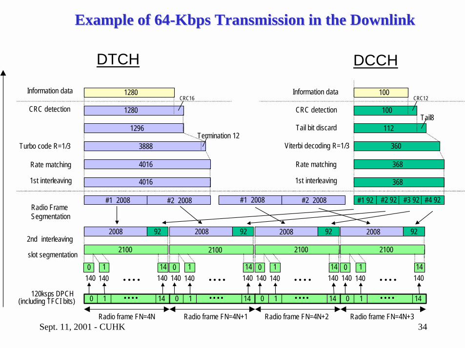
Turbo code R=1/3
Radio frame FN=4N+1 Radio frame FN=4N+2 Radio frame FN=4N+3Radio frame FN=4N
Information data
CRC detection
2nd interleaving 2100
2008 92 2008 92 2008 92 2008
#1 2008 #2 2008 #1 92 #2 92 #3 92 #4 92
2100 2100 2100
4016
3888
1296
CRC16
1280
1280
92
368
360
100CRC12
Rate matching 1st interleaving
CRC detection
Information data
DTCH DCCH
4016
#1 2008 #2 2008
368
100
Radio Frame Segmentation
slot segmentation
120 ksps DPCH (including TFCI bits)
Rate matching
1st interleaving
0 1 14• • • •
140 140 0 1
140• • • •14
0 1 14• • • •
140 1400 1
140• • • •14
0 1 14• • • •
140 140 0 1
140• • • •14
0 1 14• • • •
140 1400 1
140• • • •14
Termination 12112
Tail8Tail bit discard
Viterbi decoding R=1/3
Example of 64Example of 64--Kbps Transmission in the DownlinkKbps Transmission in the Downlink
Sept. 11, 2001 - CUHK 35
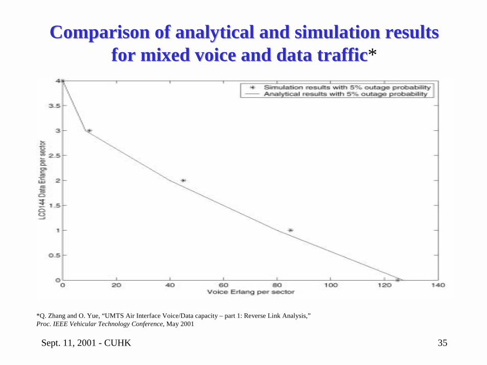
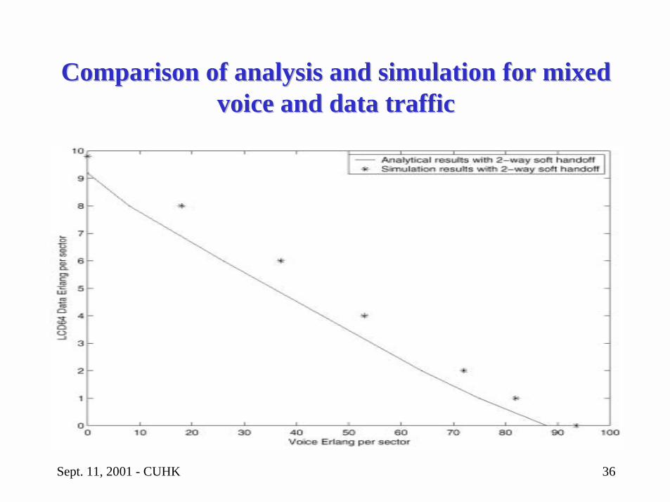
Comparison of analytical and simulation results Comparison of analytical and simulation results for mixed voice and data trafficfor mixed voice and data traffic*
*Q. Zhang and O. Yue, “UMTS Air Interface Voice/Data capacity – part 1: Reverse Link Analysis,” Proc. IEEE Vehicular Technology Conference, May 2001
Sept. 11, 2001 - CUHK 36
Comparison of analysis and simulation for mixed Comparison of analysis and simulation for mixed voice and data trafficvoice and data traffic
Sept. 11, 2001 - CUHK 37
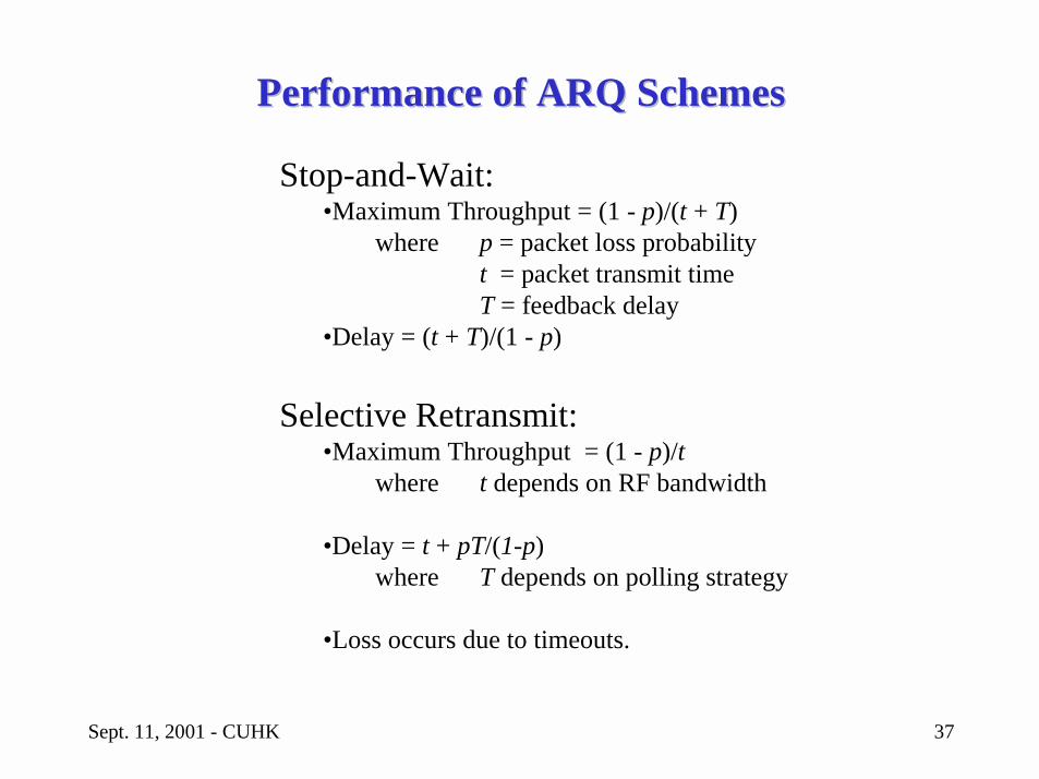
Performance of ARQ SchemesPerformance of ARQ Schemes
Stop-and-Wait:•Maximum Throughput = (1 - p)/(t + T)
where p = packet loss probabilityt = packet transmit timeT = feedback delay
•Delay = (t + T)/(1 - p)
Selective Retransmit:•Maximum Throughput = (1 - p)/t
where t depends on RF bandwidth
•Delay = t + pT/(1-p)where T depends on polling strategy
•Loss occurs due to timeouts.
Sept. 11, 2001 - CUHK 38
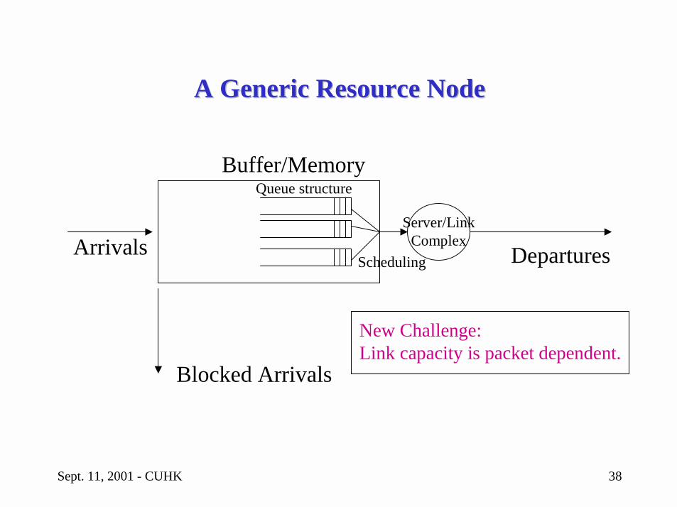
A Generic Resource NodeA Generic Resource Node
Arrivals
Buffer/Memory
Departures
Queue structure
Scheduling
Server/LinkComplex
Blocked Arrivals
New Challenge:Link capacity is packet dependent.
Sept. 11, 2001 - CUHK 39
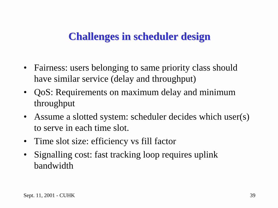
Challenges in scheduler designChallenges in scheduler design
• Fairness: users belonging to same priority class should have similar service (delay and throughput)
• QoS: Requirements on maximum delay and minimum throughput
• Assume a slotted system: scheduler decides which user(s) to serve in each time slot.
• Time slot size: efficiency vs fill factor• Signalling cost: fast tracking loop requires uplink
bandwidth
Sept. 11, 2001 - CUHK 40
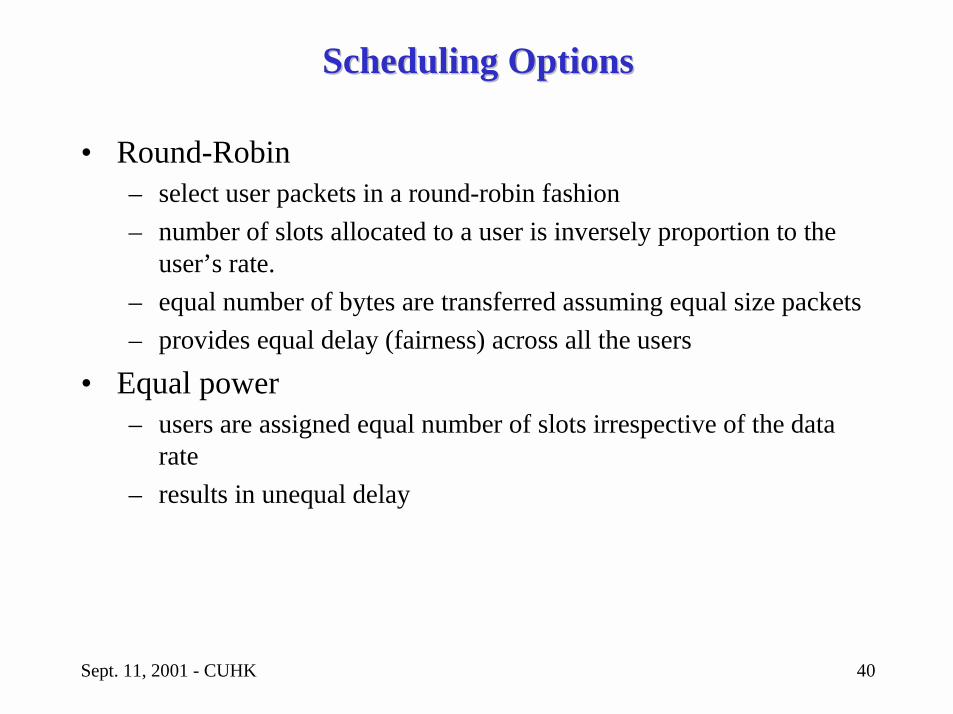
Scheduling OptionsScheduling Options
• Round-Robin– select user packets in a round-robin fashion– number of slots allocated to a user is inversely proportion to the
user’s rate.– equal number of bytes are transferred assuming equal size packets– provides equal delay (fairness) across all the users
• Equal power– users are assigned equal number of slots irrespective of the data
rate– results in unequal delay
Sept. 11, 2001 - CUHK 41
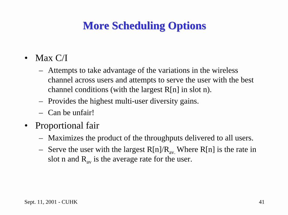
More Scheduling OptionsMore Scheduling Options
• Max C/I – Attempts to take advantage of the variations in the wireless
channel across users and attempts to serve the user with the best channel conditions (with the largest R[n] in slot n).
– Provides the highest multi-user diversity gains.– Can be unfair!
• Proportional fair – Maximizes the product of the throughputs delivered to all users.– Serve the user with the largest R[n]/Rav. Where R[n] is the rate in
slot n and Rav is the average rate for the user.
Sept. 11, 2001 - CUHK 42
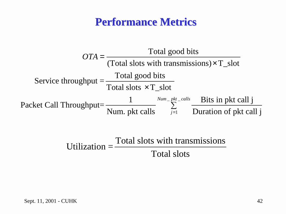
Performance MetricsPerformance Metrics
_
1
Total good bits(Total slots with transmissions) T_slot
Total good bitsService throughput =Total slots T_slot
1 Bits in pkt call jPacket Call Throughput=Num. pkt calls Duration of pkt call j
Num pk
j
OTA
=
=×
×_t calls
�
Total slots with transmissionsUtilization =Total slots
Sept. 11, 2001 - CUHK 43
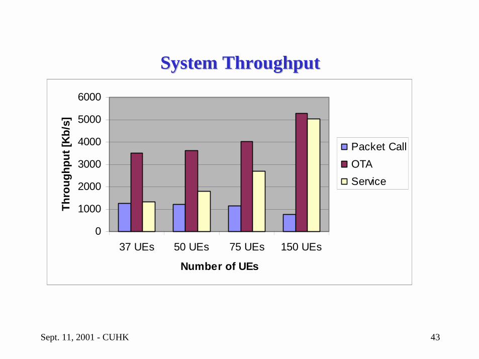
System ThroughputSystem Throughput
0
1000
2000
3000
4000
5000
6000
37 UEs 50 UEs 75 UEs 150 UEs
Number of UEs
Thro
ughp
ut [K
b/s]
Packet CallOTAService
Sept. 11, 2001 - CUHK 44
OutlineOutline
• Introduction to QoS Engineering• Overview of UMTS Architecture• QoS Engineering of Core Network• QoS Engineering of Radio Access Network• Future Design Challenges
Sept. 11, 2001 - CUHK 45
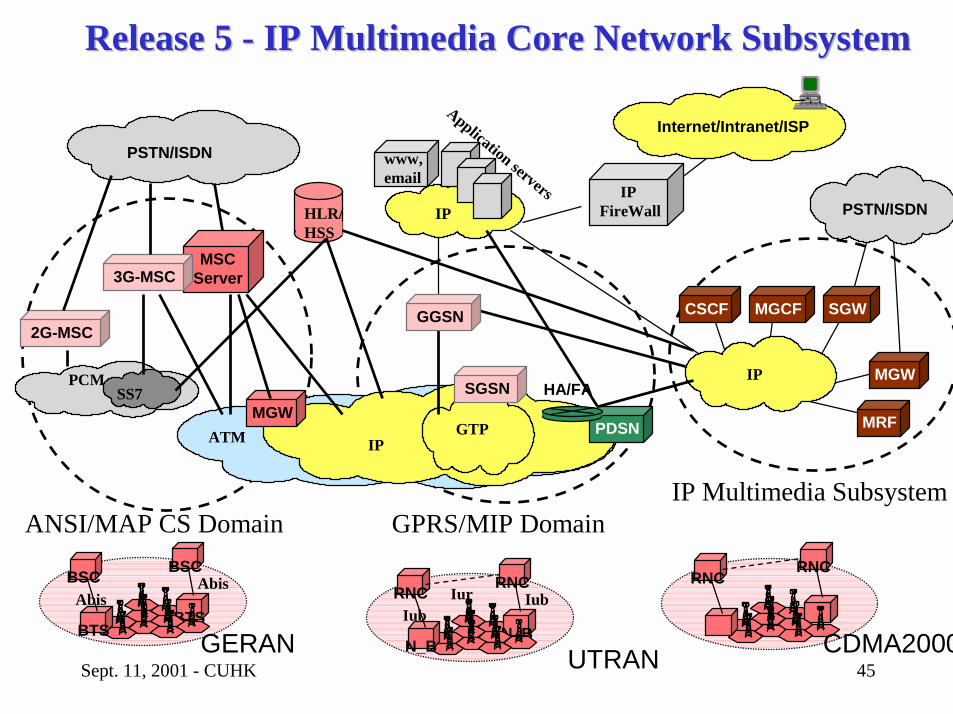
Release 5 Release 5 -- IP Multimedia Core Network SubsystemIP Multimedia Core Network Subsystem
MGCFCSCF
MRF
SGW
Internet/Intranet/ISPPSTN/ISDN
Application servers
ATM
www, email
IP
PCMSS7
IPFireWall
IP
PSTN/ISDNHLR/HSS
MGW
MSCServer3G-MSC
2G-MSC
IP
N_BN_B
RNC RNC
IubIubIur
UTRAN
BTSBTS
BSC BSC
AbisAbis
GERAN
RNC RNC
CDMA2000
GTP
SGSNMGW
PDSN
HA/FA
ANSI/MAP CS Domain GPRS/MIP DomainIP Multimedia Subsystem
GGSN