Embed Size (px)
Citation preview

University of Wisconsin Madison
Engineering World Health: BrightWater Filtration Biomedical Engineering
Team Leader: Brad Lindevig Communicator: Nick Shiley
BSAC: Karin Rasmussen BWIG: Claire Wardrop
Clients: Dr. James Shropshire: University of Wisconsin Madison Dpt. Of Family Medicine Advisors: Professor John Webster and Amit Nimunkar
1
Table of Contents
Abstract…………….………………………………………………………..………………………………2
I. Introduction …………………………………………………………..….………………………………..2
II. Design Criteria/Problem Statement………….………………………………………………….3
III. Prototype………………………………….……..………………………………………………………….5
IV. Methods……………………………………..….…………………………………………………………..8
V. Results…………………………..……………….………………………………………………………….10
VI. Conclusion……………….…………………………………………………….………………………….11
VII. Future Work……………………………………………………….…………………………………….11
VIII. References………………………………………………………………………..…………………….13
IX. Appendix……………………………………………………………………………….………………….13
X. PDS…………………………………………………………………………………………………………….14
2
Abstract
Water-related diseases are illnesses directly caused by consuming contaminated water.
Although water-related diseases have largely been eliminated in developed nations, they
remain a major concern in much of the developing world. Clean water is a pre-requisite for
reducing the spread of water-related diseases. Our group has designed an innovative water
purification system that is low cost, environmentally friendly, self-sustaining, efficient, and low
maintenance. This design is currently targeted towards the Punta Gorda, Belize area but can be
used in any region.
I. Introduction
Currently there are an estimated 1.1 billion people without access to purified drinking
water, and 2.4 billion people living without adequate sanitation. Due to this lack of purified
drinking water, many deaths worldwide result from consuming impure water. In a study by
Lenntech (2004), an estimated 2,213,000 deaths occurred annually from water-related
diseases. If safe drinking water was not made available, as many as 135 million people will die
from water-related diseases by the year 2020 (Lenntech, 2004). These water-related diseases
arise from human or animal feces, poor personal hygiene, parasites found in intermediate
organisms, or insect vectors such as mosquitoes (Lenntech, 2004). Many of these deaths can
be prevented with the introduction of a water purification system.
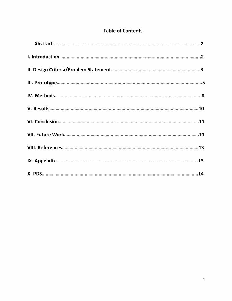
Popular methods for purifying water that are currently on the market are reverse
osmosis, ultraviolet (uv) radiation, and chlorination. Osmosis occurs when fluids containing
different concentrations of solute are separated by a barrier that is only permeable to water.
3
Figure 1: An example of a reverse osmosis system (APEC, 2011).
The uneven concentrations create an osmotic pressure gradient, and water flows from areas of
low to high solute concentrations. As the name implies, reverse osmosis systems moves water
from areas of high to low solute concentration. A
semi-permeable membrane is inserted into the
water system that contains pores that only allow
molecules with a molecular weight under
100g/mol to pass through. Colloids, ionized salts,
organic molecules, and certain bacteria are,
therefore, unable to enter the water system. Reverse osmosis is accomplished by creating a
water pressure that is greater than the natural osmotic pressure created by the difference in
solute concentration, and the filtered water that is free of bacteria and dirt flows into a
separate piping system. Figure 1 shows a typical reverse osmosis system (APEC, 2011).
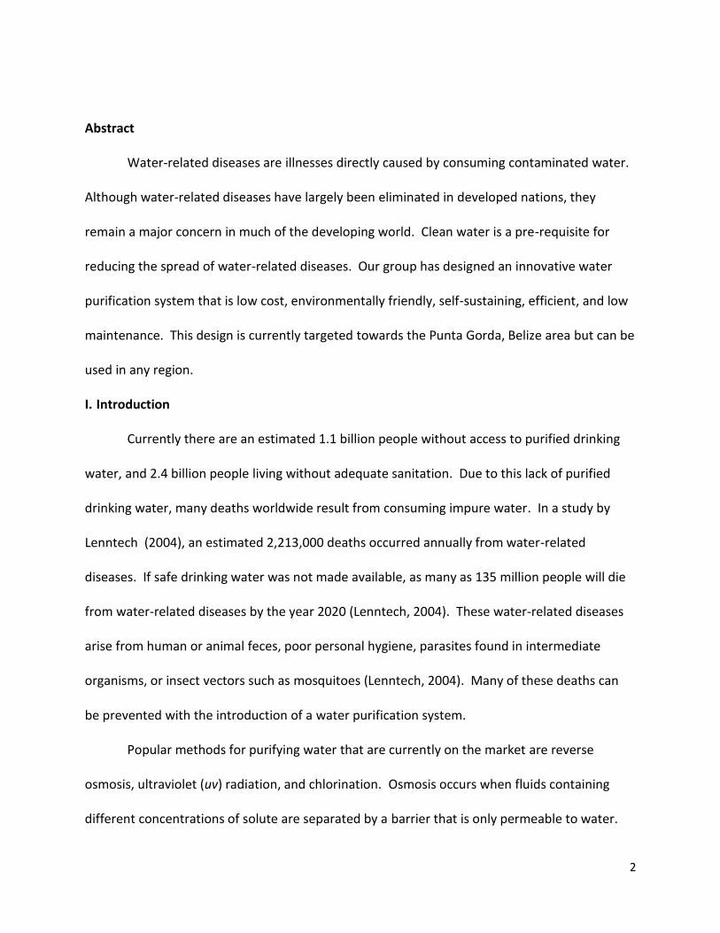
Ultraviolet light (uv) sterilization neutralizes hazardous
bacteria using within a wavelength range of 200 to 300 nm.
Impure water is exposed to uv radiation when flowing through a
chamber containing a uv lamp enclosed in a protective quartz
sleeve. Bacteria’s DNA and RNA absorb the uv radiation at 254
nm. This interferes with DNA replication during cell division
which causes the cell to be unable to proliferate.
Drawbacks of uv sterilization are that it does not remove
dirt, minerals, or harmful chemicals. The water needs to be
clear enough for the uv radiation to properly transmit through the water and affect the
Figure 2: An example of a UV Sterilization device (APEC, 2011).
4
bacteria. Finally, bacteria proliferate and grow back after exposure to uv is complete (Lenntech,
2011).
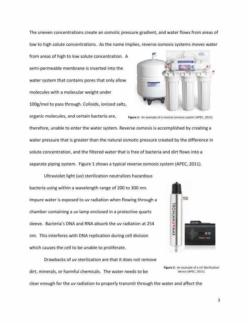
The chlorination method is considered the most effective
type of sterilization. It is currently how tap water is purified in
the U.S. (APEC, 2011). Chlorine kills bacteria by oxidizing their
cell walls and disrupting their metabolic pathways. When
chlorine is added to water, it follows the reaction: Cl2 + H20 ↔
HOCl + HCl. The hypo-chloric acid (HOCl) kills bacteria by
oxidizing cell walls (GE, 2011). Not only does chlorine kill
bacteria, it also removes ammonia, unpleasant tastes, reduces
the color of the water, destroys organic matter, and oxidizes
hydrogen sulfide, iron, and manganese (B&B, 2011).
One major concern with the use of chlorine is the creation of the byproduct
trihalomethanes (THM). It has been shown that THM can cause liver, kidney, and central
nervous system problems, as well as increase the risk of cancer (Lenntech, 2011). According to
the World Health Organization (WHO), chlorine is safe to use as long as it is used in
concentrations less than 5 mg/L (Home Purifiers, 2011), but in the US it must remain under 4
mg/L (Lenntech, 2011).
Other concerns with the chlorinator, and other water purifications systems for that
matter, is that they require replacement parts over time, chemicals and energy. Many of these
items are expensive and difficult to order for citizens of developing regions around the world.
Figure 3: An example of a chlorination device (APEC, 2011).
5
We have developed a prototype that demonstrates how to make a completely self-sustainable,
affordable water filtration device that utilizes the sun’s energy to purify water.
II. Design Criteria/Problem Statement
Our client, Dr. James Shropshire at the University of Wisconsin-Madison Department of
Family Medicine, leads a group of medical students and other health care professionals on a
medical mission trip every year to the developing region of Punta Gorda, Belize. The local clinic
of Punta Gorda, called the Hillside Clinic, has an inadequate water filtration system and water
filtration is non-existent in the surrounding regions. Dr. Shropshire provided multiple design
criteria to purify the water supply at the Hillside Clinic:
1. The system must rid the water supply of bacteria, pesticides, viruses and other toxic
chemicals comparable to other filtration methods.
2. It must be made from resources found locally in case the system requires repair it or an
update. In order to incorporate this design into the local developing regions the water
filtration system must be low maintenance and fairly simple to use.
3. The water filtration system design must be environmentally
friendly.
III. BrightWater Prototype
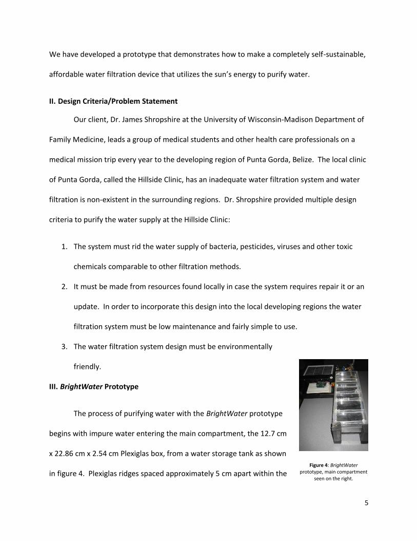
The process of purifying water with the BrightWater prototype
begins with impure water entering the main compartment, the 12.7 cm
x 22.86 cm x 2.54 cm Plexiglas box, from a water storage tank as shown
in figure 4. Plexiglas ridges spaced approximately 5 cm apart within the
Figure 4: BrightWater prototype, main compartment
seen on the right.
6
main compartment serve two purposes: to slow down the water flow to allow more purification
time, and to hold the 6mm long, 2mm diameter, titanium dioxide (TiO2) borosilicate resin glass
beads in place.
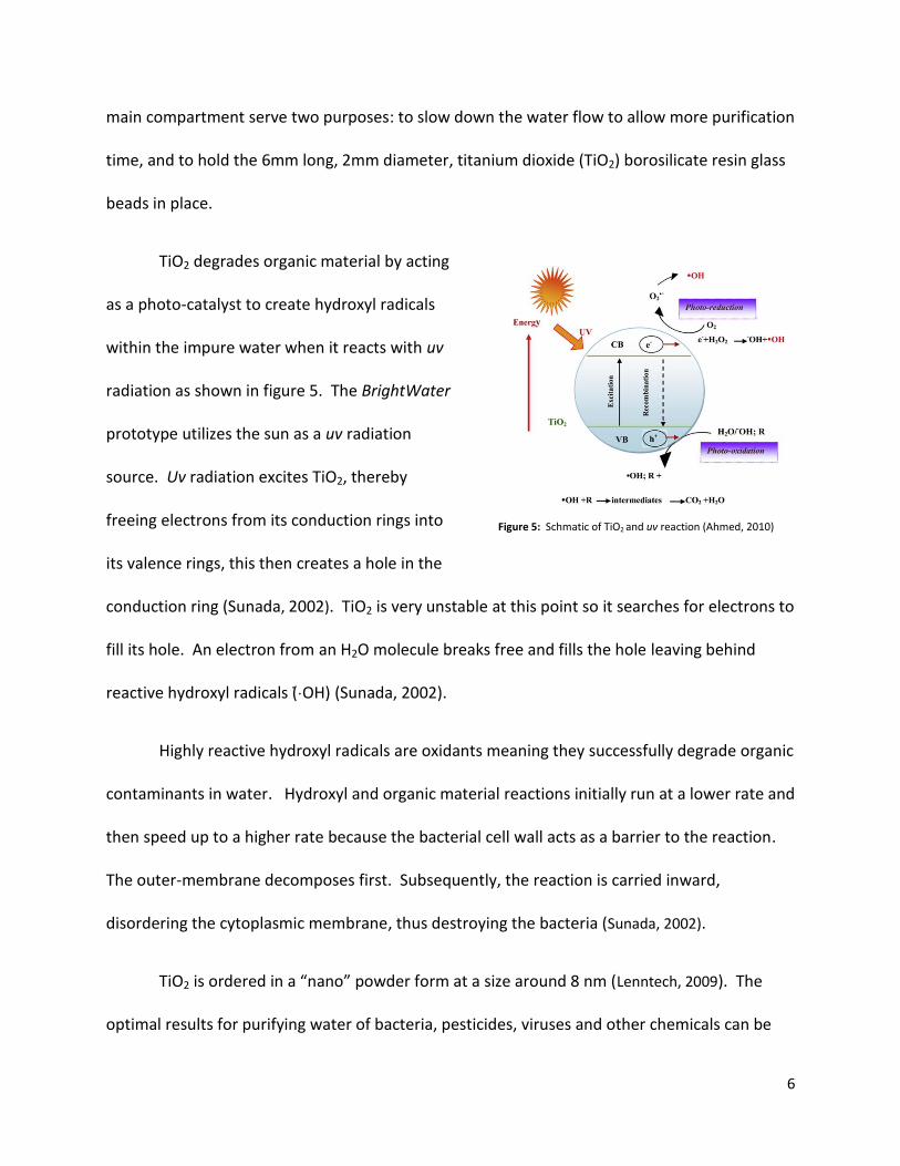
TiO2 degrades organic material by acting
as a photo-catalyst to create hydroxyl radicals
within the impure water when it reacts with uv
radiation as shown in figure 5. The BrightWater
prototype utilizes the sun as a uv radiation
source. Uv radiation excites TiO2, thereby
freeing electrons from its conduction rings into
its valence rings, this then creates a hole in the
conduction ring (Sunada, 2002). TiO2 is very unstable at this point so it searches for electrons to
fill its hole. An electron from an H2O molecule breaks free and fills the hole leaving behind
reactive hydro yl radicals (Sunada, 2002).
Highly reactive hydroxyl radicals are oxidants meaning they successfully degrade organic
contaminants in water. Hydroxyl and organic material reactions initially run at a lower rate and
then speed up to a higher rate because the bacterial cell wall acts as a barrier to the reaction.
The outer-membrane decomposes first. Subsequently, the reaction is carried inward,
disordering the cytoplasmic membrane, thus destroying the bacteria (Sunada, 2002).
TiO2 is ordered in a “nano” powder form at a size around 8 nm Lenntech, 2009). The
optimal results for purifying water of bacteria, pesticides, viruses and other chemicals can be
Figure 5: Schmatic of TiO2 and uv reaction (Ahmed, 2010)
7
achieved by treating impure water in a sealed borosilicate glass compartment, filled with TiO2
coated borosilicate glass resin beads. Borosilicate glass is necessary because it permits uv
penetration.
One major advantage of TiO2 coated borosilicate glass over chlorination and uv-
radiation is that bacteria is decomposed without leaving any harmful by products. TiO2 acts as a
catalyst which means the coating does not wear off the borosilicate glass. This means the user
does not have to recoat the borosilicate glass, thus reducing the cost of use over time as
compared to replacing semi-permeable membranes as seen in the reverse osmosis technique.
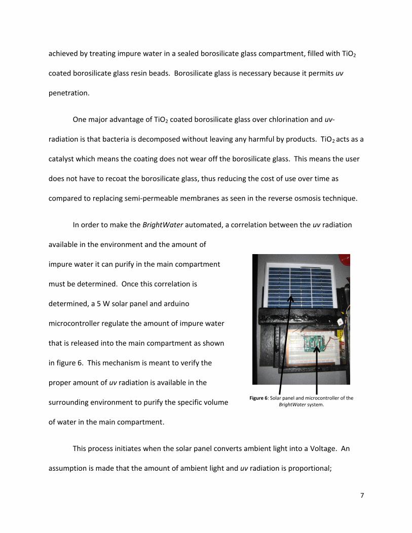
In order to make the BrightWater automated, a correlation between the uv radiation
available in the environment and the amount of
impure water it can purify in the main compartment
must be determined. Once this correlation is
determined, a 5 W solar panel and arduino
microcontroller regulate the amount of impure water
that is released into the main compartment as shown
in figure 6. This mechanism is meant to verify the
proper amount of uv radiation is available in the
surrounding environment to purify the specific volume
of water in the main compartment.
This process initiates when the solar panel converts ambient light into a Voltage. An
assumption is made that the amount of ambient light and uv radiation is proportional;
Figure 6: Solar panel and microcontroller of the BrightWater system.
8
however, a correlation can be determined with a uv detector incorporated with the
microcontroller. The rectified voltage from the solar panel is sent to the arduino
microcontroller where it compares the rectified voltage to a voltage threshold preset by the
user. If the rectified Voltage surpasses the threshold, then the arduino microcontroller sends a
5 V pulse to a servo motor to open a water valve half a turn. This releases a certain amount of
impure water into the main compartment to be purified. If the environment does not have
sufficient uv radiation to purify the water in the main compartment, such as during the night or
a really cloudy day, the microcontroller will not send the pulse and the water valve will remain
closed.
IV. Methods
In order to ensure that the system purifies water, testing was done at the Water Science
and Engineering Laboratory at UW Madison. The following procedure was followed for each
experiment:
1. Prepare 4 sets of 3 (12 total) agar plates.
2. Take sample of raw lake water obtained from Lake Treatment building.
a. Dilute sample using deionized water at a 1:100 ratio
i. Place 4.5 mL of sterilized dIH2O in a vial.
ii. Add 0.5mL of the sample to the vial. This creates a 1:10 dilution. Mix the
sample thoroughly to ensure equal distribution of the water.
iii. Place 4.5 mL of sterilized dIH2O in a new vial.
9
iv. Add 0.5 mL of the 1:10 dilution to vial created in 2aiii. This creates a
1:100 sample. Mix the sample thoroughly to ensure equal distribution of
the water.
b. Create 3 agar samples each with 100uL of the diluted lake water
i. Remove the water from the top of the agar container using a sterilized
wand.
ii. Add 100 μL of the 1:100 lake dilution onto the agar plate. Using the
wand, evenly distribute the water onto the entire agar place to ensure
equal bacteria distribution.
iii. Do not forget to label and date each plate.
c. Set aside and repeat steps 2a. and 2b. using the Lake Treatment purified water.
Use step 2 as controls.
3. Perform the uv control test.
a. Thoroughly wash Plexiglas box.
b. Set the box at a six degree angle. Place the uv lamp (115V, 0.17 amps, SW
254nm) 19.7 cm above the box running parallel to the box. The produces a uv
radiation index of 2-5 on the main compartment.
c. Connect the funnel to the top of the valve. Insert tube connected the bottom of
the valve into the hole at the top of the main compartment.
d. Obtain 1200 mL of raw lake water from the same source in step 2. Record the
amount and use the same amount for every subsequent trial.
10
e. Evenly distribute 15 marbles in the main compartment. 15 marbles corresponds
to the same amount of volume taken up in the box as compared to the
borosilicate glass beads.
f. Turn on the uv lamp and turn off all other light sources.
g. Pour the lake water into funnel and let run through box when the water valve is
set at a half a turn.
h. Record the time it takes for the water to flow through the system.
i. Begin when water first enters the funnel.
ii. Stop when water first leave the box.
i. Obtain the sample midstream in a vial as it flows out of the bottom of the box.
j. (Optional) Let the water sit in the box for 20 minutes.
k. Collect a sample from the box.
l. Repeat Steps 2a and 2b to create agar plates of the midstream sample (and the
20 minute sample if taken).
4. Perform the TiO2/uv test.
a. Repeat steps 3a – 3i but replace the marbles with TiO2 covered beads.
5. Perform regrowth tests.
a. Place the uv sample and TiO2/uv samples in a secure location overnight.
b. Return the next day and repeat steps 2a and 2b for each sample.
6. Incubate all samples for 5 days. Count and record the number of bacteria colonies on
the fifth day.
11
V. Results
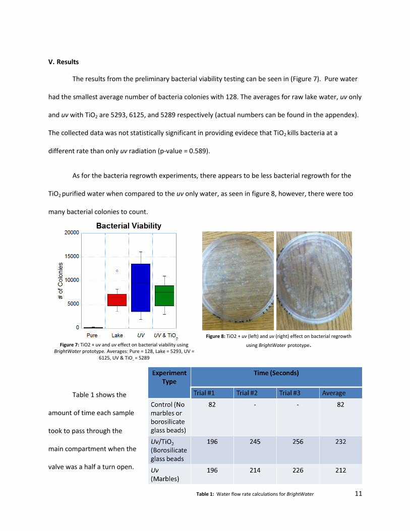
The results from the preliminary bacterial viability testing can be seen in (Figure 7). Pure water
had the smallest average number of bacteria colonies with 128. The averages for raw lake water, uv only
and uv with TiO2 are 5293, 6125, and 5289 respectively (actual numbers can be found in the appendex).
The collected data was not statistically significant in providing evidece that TiO2 kills bacteria at a
different rate than only uv radiation (p-value = 0.589).
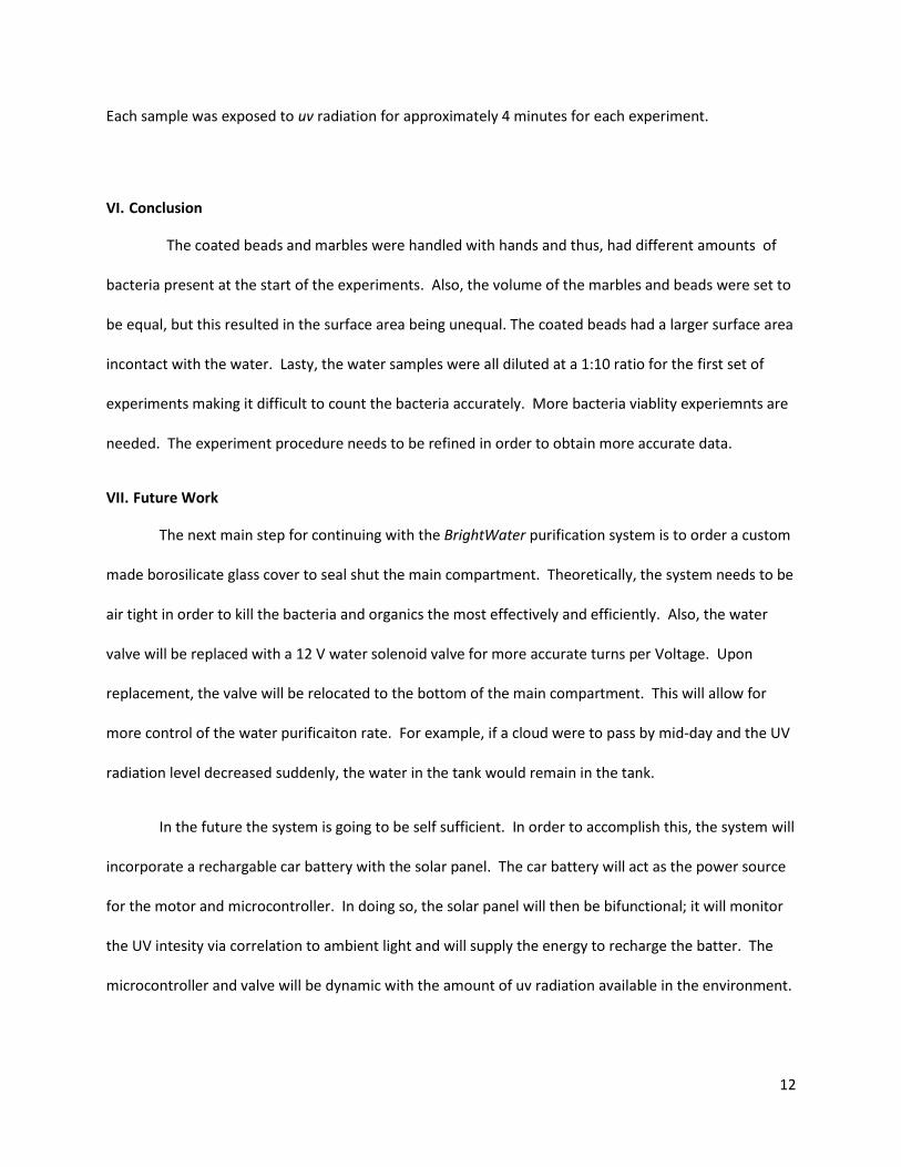
As for the bacteria regrowth experiments, there appears to be less bacterial regrowth for the
TiO2 purified water when compared to the uv only water, as seen in figure 8, however, there were too
many bacterial colonies to count.
Table 1 shows the
amount of time each sample
took to pass through the
main compartment when the
valve was a half a turn open.
Table 1: Water flow rate calculations for BrightWater
Figure 8: TiO2 + uv (left) and uv (right) effect on bacterial regrowth
using BrightWater prototype. Figure 7: TiO2 + uv and uv effect on bacterial viability using BrightWater prototype. Averages: Pure = 128, Lake = 5293, UV =
6125, UV & TiO2
= 5289
12
Each sample was exposed to uv radiation for approximately 4 minutes for each experiment.
VI. Conclusion
The coated beads and marbles were handled with hands and thus, had different amounts of
bacteria present at the start of the experiments. Also, the volume of the marbles and beads were set to
be equal, but this resulted in the surface area being unequal. The coated beads had a larger surface area
incontact with the water. Lasty, the water samples were all diluted at a 1:10 ratio for the first set of
experiments making it difficult to count the bacteria accurately. More bacteria viablity experiemnts are
needed. The experiment procedure needs to be refined in order to obtain more accurate data.
VII. Future Work
The next main step for continuing with the BrightWater purification system is to order a custom
made borosilicate glass cover to seal shut the main compartment. Theoretically, the system needs to be
air tight in order to kill the bacteria and organics the most effectively and efficiently. Also, the water
valve will be replaced with a 12 V water solenoid valve for more accurate turns per Voltage. Upon
replacement, the valve will be relocated to the bottom of the main compartment. This will allow for
more control of the water purificaiton rate. For example, if a cloud were to pass by mid-day and the UV
radiation level decreased suddenly, the water in the tank would remain in the tank.
In the future the system is going to be self sufficient. In order to accomplish this, the system will
incorporate a rechargable car battery with the solar panel. The car battery will act as the power source
for the motor and microcontroller. In doing so, the solar panel will then be bifunctional; it will monitor
the UV intesity via correlation to ambient light and will supply the energy to recharge the batter. The
microcontroller and valve will be dynamic with the amount of uv radiation available in the environment.
13
VIII. References
1. Amed S., Rasul M.G., Brown R., ashib M.A. 2010. “Influence of parameters on the heterogeneous photocatalytic degradation of pesticides and phenolic contaminants in wastewater: A short review.” J. of Environ. Management.
2. Sunada, K., T. Watanabe, and K. ashimoto. “Studies on photo-killing of bacteria on TiO2 thin film.” J. of Photochemistry and Photobiology. (2002).
3. Water Treatment Chemicals. 2009. Lenntech. 10 February 2011 www.lenntech.com/products/chemicals/water-treatment-chemicals.htm#Disinfectants
4. APEC. Water Purification vs. Basic Filtration. Retrieved from http://www.freedrinkingwater.com/water-education/quality-water-purification.htm
5. Lenntech Water Treatment Solutions. Water Treatment Chemicals. Retrieved from www.lenntech.com/products/chemicals/water-treatment-chemicals.htm#Disinfectants
6. GE Power & Water. Chapter 27 – Chlorine and Chlorine Alternatives. Retrieved from http://www.gewater.com/handbook/cooling_water_systems/ch_27_chlorine.jsp
7. Home Water Purifiers and Filters. Ultraviolet Water Purification. Retrieved from http://www.home-water-purifiers-and-filters.com/ultraviolet-filter.php
8. World Health Organization (WHO). Water supply, sanitation, and hygiene development. Retrieved from http://www.who.int/water_sanitation_health/hygiene/en/
9. (B&B, 2011) B&B Chlorination. How a Dry Pellet Chorinator works. Retrieved from http://www.bbchlor.com/how.htm
IX. Appendix
Materials
Funnel
Water Valve
Tubing to connect the valve to the system
Plexiglas box with ridges
TiO2 coated borosilicate resin beads
Marbles (quantity should be adjusted so that total volume of the marbles is the same as the total volume of the beads)
Uv lamp
12 agar plates
Glass vials
Sterilized deionized water
Lake water from Lake Mendota
Purified water from the UW Madison Water Treatment plant
14
X. PDS
Product Design Specifications: PDS Engineering World Health (EWH) Water Filtration Project Team Roles: Team Leader: Brad Lindevig Communicator: Nick Shiley BSAC: Karin Rasmussen BWIG: Claire Wardrop Last Update: March 3rd, 2011
Problem Statement: Many people in developing regions around the world have either limited access or one at all to purified drinking water due to contaminated water sources. This problem results in preventable diseases and even death. Water filtration systems are necessary to rid the local water from bacteria, pesticides and viruses. In order to make these systems effective in the respective regions they must be made from material found near the region of interest, require low maintenance and be efficient. Function: Our design filters dirt particles, bacteria, pesticides and other toxic chemicals from water. It is completely self-sufficient because it uses solar energy and a photo-catalyst. Client Requirements:
• Sterilizes water found all around the world. • Can transport the device, or sterilized water to rural regions of developing countries
Design Requirements: 1. Physical and Operational Characteristics
a. Performance Requirements: Must produce purified water at an efficient rate. The water will be used to drink from and clean infections and wounds. b. Safety: It must clear the water of bacteria such as giardia and e-coli, pesticides and other toxic chemicals. c. Accuracy and Reliability: A system must be in place to measure the purity of the water from time to time. d. Life in Service: Must last at least a year in service. Health professionals are only able to make one trip a year to developing regions. If it breaks down we cannot expect the people there to fix it no matter how easy it is. e. Shelf Life: Storing the product will have no effect on its ability to perform. f. Operating Environment: This device will be used in developing countries around the world, specifically outside on the sides of houses. g. Ergonomics: The device should be able to be operated by an untrained adult, but settings should be determined by a professional. h. Size: The device should be compact and easily portable. i. Weight: The device should be light enough to be lifted by a child. j. Materials: The device should utilize materials that can be found in the area it is used in. k. Aesthetics, Appearance, and Finish: Not applicable.