Embed Size (px)
Citation preview
ENVIRONMENTAL MANAGEMENT PLAN
“BAY HILLS”
ANANDA HOMES PVT. LTD.
(Residential Complex)
Sy. No. 93 (Part),95 (Part) & 96,
Neknampur Village,
Gandipet (Earlier RajendraNagar) Mandal,
Ranga Reddy District,
Telangana
Prepared by
Flat no: 7-3, Dhruvatara Apartments, Amrutha Estates, Somajiguda,
Hyderabad - 500 082; Ph: 040- 23314270 /271/ 66100103
Environmental Management Plan “BAY HILLS” ANANDA HOMES PVT. LTD. Residential Complex
1
1.0 INTRODUCTION
M/s Ananda Homes Pvt. Ltd., has proposed to construct a Residential complex
under the banner “BAY HILLS” at Sy. No. 93 (Part),95 (Part) & 96, Neknampur
Village, Gandipet (Earlier RajendraNagar) Mandal, Ranga Reddy District, Telangana
As per the EIA notification, 2006 amended on 1st December, 2009, Building and
Construction projects (under Item 8a) with built up area ≥20000 Sq.m and <
1,50,000 sq.mtrs are categorized under B category.
1.1 DETAILS ABOUT THE PROJECT SITE
Latitude : 17°23'15.51"N 78°21'55.63"E
Location : Sy. 93 (Part),95 (Part) & 96
Type of the area : As per the Master plan of Hyderabad
Metropolitan Development Authority the area
proposed for Complex falls under Residential
zone (approved by Govt. vide G.O MS. NO.
288 M.A dated 03-04-2008.
Surroundings of the project site
:
North open land followed by road
East road
South private buildings
West open land followed by road
Topography : Topography of the site is more or less flay
without many undulations
Nearest Railway station :
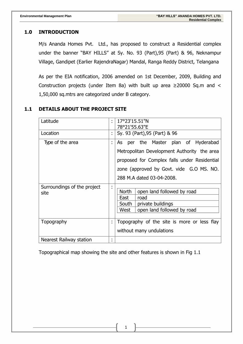
Topographical map showing the site and other features is shown in Fig 1.1
Environmental Management Plan “BAY HILLS” ANANDA HOMES PVT. LTD. Residential Complex
2 | P a g e
PROPOSED
PROJECT SITE
TOPOGRAPHICAL MAP SHOWING THE LOCATION OF THE PROJECT SITE ( Fig 1.1)
Environmental Management Plan “BAY HILLS” ANANDA HOMES PVT. LTD. Residential Complex
3
2.0 DETAILS OF THE PROJECT
The following are the brief details of the proposed Residential complex project site
S.No Details Description
i. Total Land Area Total: 21,196.57 Sq.m
ii. Survey nos. Sy.No. 93 (Part),95 (Part) & 96
iii. Expected project cost Rs. 129.6 Crores
iv. Total built-up area
80,150.13 Sq.m
Area statement for the proposed Residential
Complex project is furnished in Table 1.1
v. Water Requirement Total water demand is about 4 KLD during
Construction of Residential complex &
240 KLD during the operation of Residential
complex
Source of supply : Municipal supply
vi. Power requirement 1600 KvA (Maximum peak demand)
vii. Solid waste generation During operational phase:
Municipal solid waste : 0.81 MT/day
viii. Connectivity The proposed Residential complex site is well
connected by Osman sagar road followed by road
leading to Alkapuri.
ix. Additional facilities DG Sets
Sewage Treatment Plant
and other amenities
x. Back up supply DG sets of capacities 4 x 200 kVA will be provided
for backup supply
xi. Parking facilities 28,349.93 Sq.m (54.7 % of total floor area)
Environmental Management Plan “BAY HILLS” ANANDA HOMES PVT. LTD. Residential Complex
4
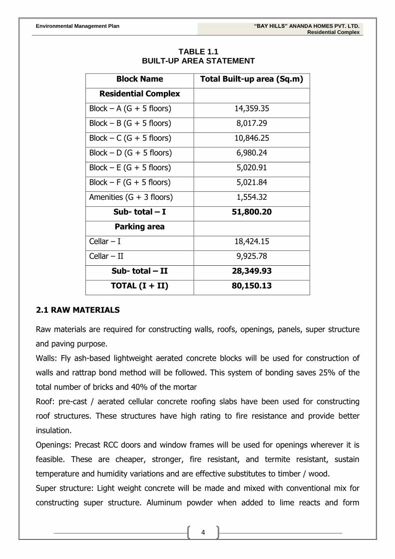
TABLE 1.1 BUILT-UP AREA STATEMENT
Block Name Total Built-up area (Sq.m)
Residential Complex
Block – A (G + 5 floors) 14,359.35
Block – B (G + 5 floors) 8,017.29
Block – C (G + 5 floors) 10,846.25
Block – D (G + 5 floors) 6,980.24
Block – E (G + 5 floors) 5,020.91
Block – F (G + 5 floors) 5,021.84
Amenities (G + 3 floors) 1,554.32
Sub- total – I 51,800.20
Parking area
Cellar – I 18,424.15
Cellar – II 9,925.78
Sub- total – II 28,349.93
TOTAL (I + II) 80,150.13
2.1 RAW MATERIALS
Raw materials are required for constructing walls, roofs, openings, panels, super structure
and paving purpose.
Walls: Fly ash-based lightweight aerated concrete blocks will be used for construction of
walls and rattrap bond method will be followed. This system of bonding saves 25% of the
total number of bricks and 40% of the mortar
Roof: pre-cast / aerated cellular concrete roofing slabs have been used for constructing
roof structures. These structures have high rating to fire resistance and provide better
insulation.
Openings: Precast RCC doors and window frames will be used for openings wherever it is
feasible. These are cheaper, stronger, fire resistant, and termite resistant, sustain
temperature and humidity variations and are effective substitutes to timber / wood.
Super structure: Light weight concrete will be made and mixed with conventional mix for
constructing super structure. Aluminum powder when added to lime reacts and form
Environmental Management Plan “BAY HILLS” ANANDA HOMES PVT. LTD. Residential Complex
5
hydrogen bubbles and light weight cementitious material is formed. This material is high
strength to weight ratio and an insulation value of R-10 in a 20.32 cm thick wall.
Paving of roads: Grass pavers will be used on the road, parking and pedestrian areas.
Grass pavers will
Reduce heat island effect
Minimize storm water runoff
Beneficial for localized aquifer recharge
Source of Raw materials
All the raw materials required for the Residential complex will be sourced from in and
around Hyderabad
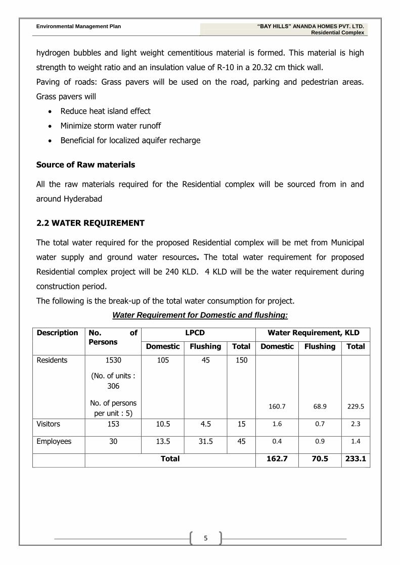
2.2 WATER REQUIREMENT
The total water required for the proposed Residential complex will be met from Municipal
water supply and ground water resources. The total water requirement for proposed
Residential complex project will be 240 KLD. 4 KLD will be the water requirement during
construction period.
The following is the break-up of the total water consumption for project.
Water Requirement for Domestic and flushing:
Description No. of
Persons
LPCD Water Requirement, KLD
Domestic Flushing Total Domestic Flushing Total
Residents 1530
(No. of units :
306
No. of persons
per unit : 5)
105 45 150
160.7 68.9 229.5
Visitors 153 10.5 4.5 15 1.6 0.7 2.3
Employees 30 13.5 31.5 45 0.4 0.9 1.4
Total 162.7 70.5 233.1
Environmental Management Plan “BAY HILLS” ANANDA HOMES PVT. LTD. Residential Complex
6
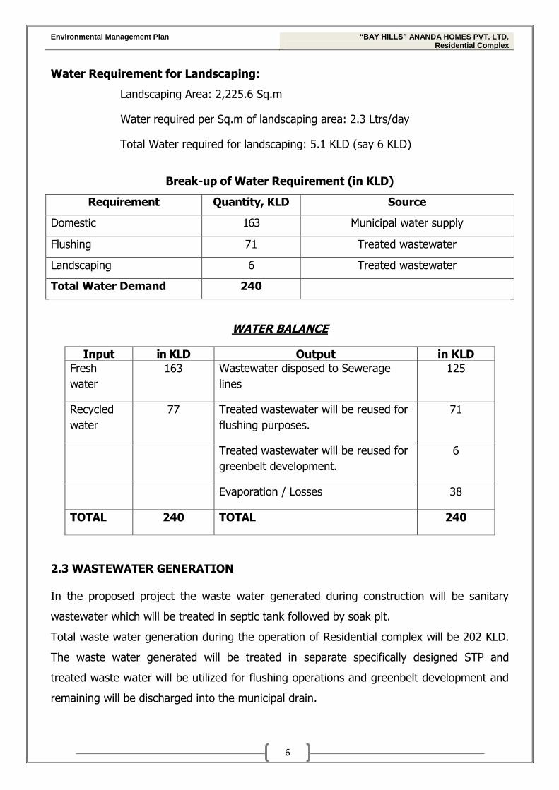
Water Requirement for Landscaping:
Landscaping Area: 2,225.6 Sq.m
Water required per Sq.m of landscaping area: 2.3 Ltrs/day
Total Water required for landscaping: 5.1 KLD (say 6 KLD)
Break-up of Water Requirement (in KLD)
Requirement Quantity, KLD Source
Domestic 163 Municipal water supply
Flushing 71 Treated wastewater
Landscaping 6 Treated wastewater
Total Water Demand 240
WATER BALANCE
Input in KLD Output in KLD
Fresh
water
163 Wastewater disposed to Sewerage
lines
125
Recycled
water
77 Treated wastewater will be reused for
flushing purposes.
71
Treated wastewater will be reused for
greenbelt development.
6
Evaporation / Losses 38
TOTAL 240 TOTAL 240
2.3 WASTEWATER GENERATION
In the proposed project the waste water generated during construction will be sanitary
wastewater which will be treated in septic tank followed by soak pit.
Total waste water generation during the operation of Residential complex will be 202 KLD.
The waste water generated will be treated in separate specifically designed STP and
treated waste water will be utilized for flushing operations and greenbelt development and
remaining will be discharged into the municipal drain.
Environmental Management Plan “BAY HILLS” ANANDA HOMES PVT. LTD. Residential Complex
7
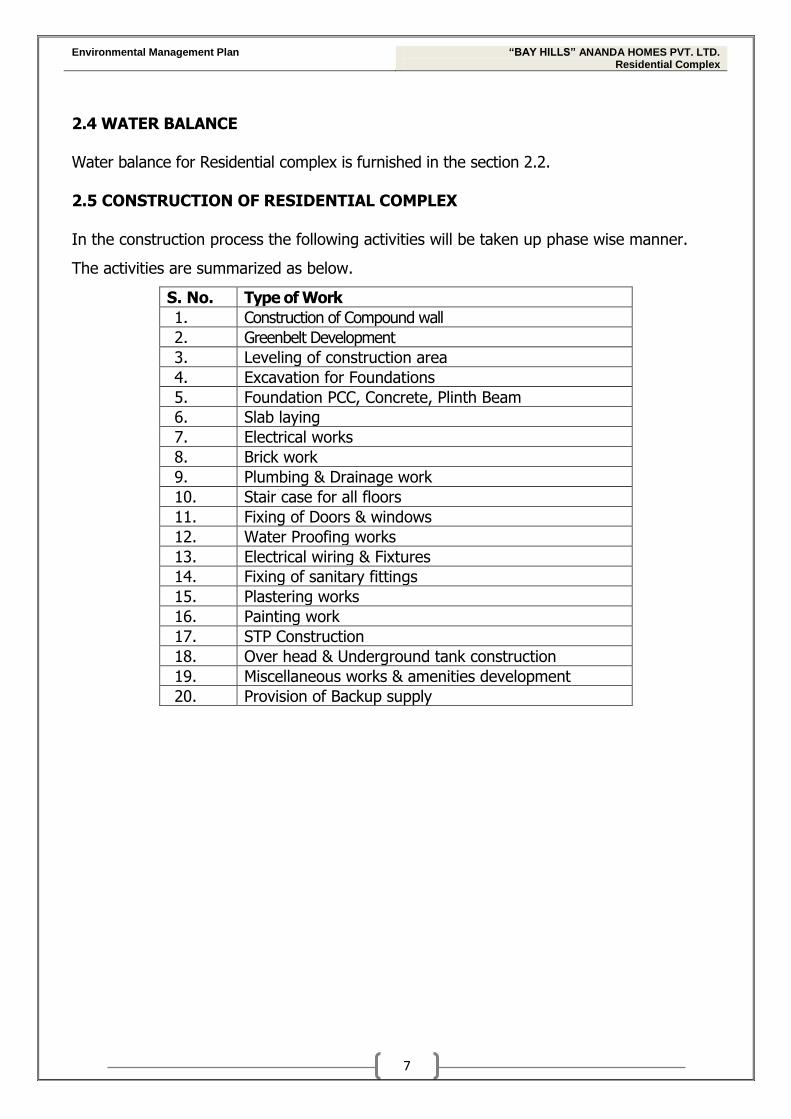
2.4 WATER BALANCE Water balance for Residential complex is furnished in the section 2.2. 2.5 CONSTRUCTION OF RESIDENTIAL COMPLEX
In the construction process the following activities will be taken up phase wise manner.
The activities are summarized as below.
S. No. Type of Work
1. Construction of Compound wall
2. Greenbelt Development
3. Leveling of construction area
4. Excavation for Foundations
5. Foundation PCC, Concrete, Plinth Beam
6. Slab laying
7. Electrical works
8. Brick work
9. Plumbing & Drainage work
10. Stair case for all floors
11. Fixing of Doors & windows
12. Water Proofing works
13. Electrical wiring & Fixtures
14. Fixing of sanitary fittings
15. Plastering works
16. Painting work
17. STP Construction
18. Over head & Underground tank construction
19. Miscellaneous works & amenities development
20. Provision of Backup supply
Environmental Management Plan “BAY HILLS” ANANDA HOMES PVT. LTD. Residential Complex
8
3.0 ENVIRONMENTAL MANAGEMENT PLAN DURING CONSTRUCTION PHASE
Environmental pollution is inevitable during the construction phase. The project proponent
should take appropriate steps to control pollution during construction phase. The following
are the factors requiring control during construction phase.
3.1 SITE PREPARATION
In the proposed project, all necessary control measures will be taken during site
preparation.
The soil type in the area of project site area is sand silty soil. Sparse vegetation is
observed in small portion of the Project area. Hence there will not be much removal
of top soil during construction activities.
To keep the damage to top soil minimum, excavators will be utilized for construction
Top soil excavated during construction activities will be stacked at safe place for
reuse at a later stage of construction.
3.2 AIR ENVIRONMENT
Dust is the major emission during the construction period. The following control
measures will be followed during the construction period
Application of dust suppressants will be done
Locally available gravel will be applied to the roads and lots, to prevent the dust
emanation
Measures will be taken to cover the stored materials to prevent the dust emission
during high winds
Speed of the vehicles in the project area will be limited 20 Kmph
Rescheduling the works during high speedy winds
Inspection will be done for use of covering sheet to prevent dust dispersion at
buildings site
3.3 WATER ENVIRONMENT Water required during the construction the residential complex will be met from the ground
water resources. Total water requirement during construction period will be 4 KLD and
construction period lasts for period of 18 months.
Environmental Management Plan “BAY HILLS” ANANDA HOMES PVT. LTD. Residential Complex
9
The following control measures will be taken to reduce the reduce the water requirement
during construction
Curing water will be sprayed on concrete structures; free flow of water will not be
done for curing.
After liberal curing on the first day, all concrete structures will be painted with
curing chemical to save water. This will stop daily water curing hence save water.
Concrete structures will be covered with thick cloth/gunny bags and then water
will be sprayed on them. This will avoid water rebound and will ensure sustained
and complete curing.
Ponds will be made using cement and sand mortar to avoid water flowing away
from the flat surface while curing.
Waste water management during construction
Waste water generation will be minimized by following above control measures
Sanitary waste water generated during construction stage will be sent to septic tank
followed by soak pit
3.4 NOISE ENVIRONMENT
The main sources of noise in the process of construction activities will be cement concrete
mixing, welding, aluminum channel folding, drilling and DG sets etc.
Diesel generator sets will be provided with integral acoustic enclosure at the
manufacturing stage itself
Equipment like earmuffs, earplugs etc. will be used for hearing protection for
workers.
3.5 LAND ENVIRONMENT 3.5.1 Solid waste generation & Management
Proper planning and management during construction period is very much vital. We
proposed to implement the following control measures to mitigate the waste generation
Delivery of material on site will be done over a durable, impervious and level
surface, so that first batch of material does not mix with the site surface. Availability
of covered storage will be assured.
Environmental Management Plan “BAY HILLS” ANANDA HOMES PVT. LTD. Residential Complex
10
The recyclable items like metal, plastic will be sent to recyclable industry, and rest of
this scrap will be stored in a covered area.
Wherever materials (aggregates, sand, etc.) are more likely to generate fine
airborne particles during operations, nominal wetting by water will be practiced.
Workers / labour will be given proper air masks and helmets.
Skilled labour and good workmanship will be employed for judicial utilization of
materials and minimizing the waste.
Proper estimate of material will be done to minimize the undue wastage.
Contaminated runoff from storage will be captured in ditches or ponds with an oil
trap at the outlet.
Materials wasted on site will be reused at the same place.
3.5.2 Waste management & recycling
The construction waste includes debris, concrete (often recycled and reused at the site),
steel and other metals, pallets, packaging and paper products, fluorescent tubes, wood
beams, joists, studs, baseboards, cabinets and cupboards, railings, brick, doors and
casings, interior windows, bathroom fixtures, light fixtures, ceiling grid and tile, furnishings
etc.
Waste recycling Plan
Waste and recycling plans will be developed prior to beginning construction activity. The
plan aims at identifying wastes to be generated, and designate handling, recycling and
disposal method to be followed.
Handling Handling of waste material requires special precautions such as personal protective
equipment and special procedures to prevent the injury. Safe operating methods will be
developed for waste collection, storage, and disposal operations in a manner to protect the
health and safety of personnel, minimize environmental impact and promote material
recovery and recycling.
Environmental Management Plan “BAY HILLS” ANANDA HOMES PVT. LTD. Residential Complex
11
Waste Segregation Gross segregation of construction wastes into roadwork materials, structural building
material, salvaged building parts and site clearance wastes will be done and additional
segregation will be done to facilitate reuse/ recycling.
Storage
Adequate provision will be made for storage of solid waste and for easy access to the
dustbins
• for labours from source to the place of storage, and
• from the place of storage to a collection point specified by the waste
collection authority and/or contractor
Three colours of wheeled bins:
o Dark grey for inert waste,
o Green for wood and ply waste and
o Blue for hazardous waste will be used.
A minimum of 4% of the total site area will be allocated for storage and pretreatment of
the waste. This storage area will be covered to prevent any impact on surrounding.
4.0 ENVIRONMENTAL MANAGEMENT PLAN DURING OPERATION PHASE 4.1 Air Emission Management
During operation of the proposed Residential complex, the emissions will be mainly from
DG Sets which will be used for backup power supply and vehicles. Emissions will be mainly
Particulate matter, NMHC, Nitrogen dioxide and Carbon monoxide.
The following control measures will be taken up during the operation
All the internal roads will be grass paved. This will reduce the dust generation due to
the vehicular movement
Stack of adequate height will be provided to the DG Sets as per CPCB guidelines
Green belt will be developed in the premises of complex which will act as sink for air
emissions
Hence there will not be any impact on surrounding environment due to the air emissions
from the proposed complex.
Environmental Management Plan “BAY HILLS” ANANDA HOMES PVT. LTD. Residential Complex
12
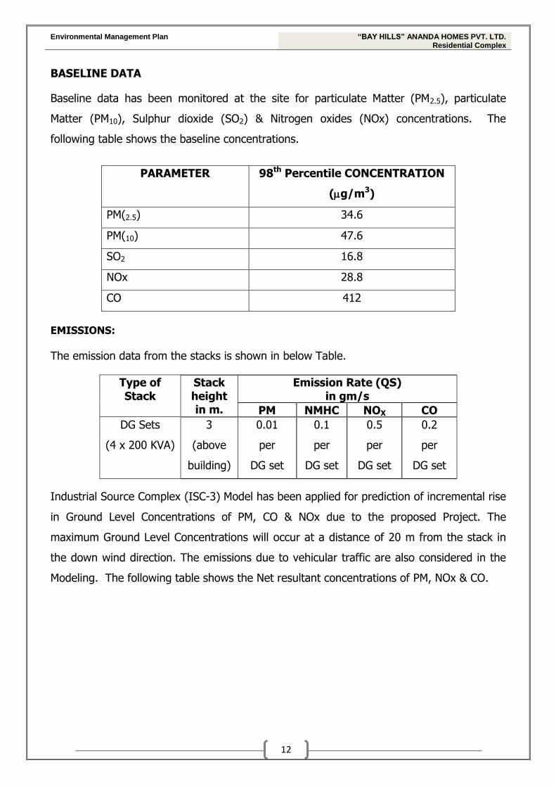
BASELINE DATA
Baseline data has been monitored at the site for particulate Matter (PM2.5), particulate
Matter (PM10), Sulphur dioxide (SO2) & Nitrogen oxides (NOx) concentrations. The
following table shows the baseline concentrations.
PARAMETER 98th Percentile CONCENTRATION
(g/m3)
PM(2.5) 34.6
PM(10) 47.6
SO2 16.8
NOx 28.8
CO 412
EMISSIONS:
The emission data from the stacks is shown in below Table.
Type of Stack
Stack height in m.
Emission Rate (QS) in gm/s
PM NMHC NOX CO
DG Sets
(4 x 200 KVA)
3
(above
building)
0.01
per
DG set
0.1
per
DG set
0.5
per
DG set
0.2
per
DG set
Industrial Source Complex (ISC-3) Model has been applied for prediction of incremental rise
in Ground Level Concentrations of PM, CO & NOx due to the proposed Project. The
maximum Ground Level Concentrations will occur at a distance of 20 m from the stack in
the down wind direction. The emissions due to vehicular traffic are also considered in the
Modeling. The following table shows the Net resultant concentrations of PM, NOx & CO.
Environmental Management Plan “BAY HILLS” ANANDA HOMES PVT. LTD. Residential Complex
13
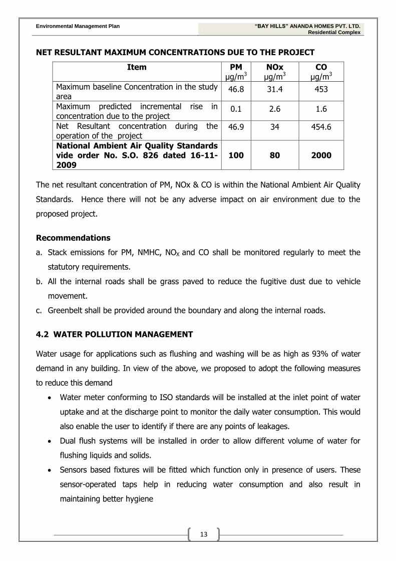
NET RESULTANT MAXIMUM CONCENTRATIONS DUE TO THE PROJECT
Item PM
µg/m3 NOx µg/m3
CO µg/m3
Maximum baseline Concentration in the study area
46.8 31.4 453
Maximum predicted incremental rise in concentration due to the project
0.1 2.6 1.6
Net Resultant concentration during the operation of the project
46.9 34 454.6
National Ambient Air Quality Standards vide order No. S.O. 826 dated 16-11-2009
100 80 2000
The net resultant concentration of PM, NOx & CO is within the National Ambient Air Quality
Standards. Hence there will not be any adverse impact on air environment due to the
proposed project.
Recommendations
a. Stack emissions for PM, NMHC, NOX and CO shall be monitored regularly to meet the
statutory requirements.
b. All the internal roads shall be grass paved to reduce the fugitive dust due to vehicle
movement.
c. Greenbelt shall be provided around the boundary and along the internal roads.
4.2 WATER POLLUTION MANAGEMENT
Water usage for applications such as flushing and washing will be as high as 93% of water
demand in any building. In view of the above, we proposed to adopt the following measures
to reduce this demand
Water meter conforming to ISO standards will be installed at the inlet point of water
uptake and at the discharge point to monitor the daily water consumption. This would
also enable the user to identify if there are any points of leakages.
Dual flush systems will be installed in order to allow different volume of water for
flushing liquids and solids.
Sensors based fixtures will be fitted which function only in presence of users. These
sensor-operated taps help in reducing water consumption and also result in
maintaining better hygiene
Environmental Management Plan “BAY HILLS” ANANDA HOMES PVT. LTD. Residential Complex
14
Tap aerators will be installed which facilitate cleaning through increasing the pressure
at which the water is delivered even at low flow rates.
Pressure reduction device will be installed which will affect the discharge rate and also
to maintain uniform flow at different levels.
Waste water generation Only source of waste water generation will be sanitary waste water which will be treated in
STP with Moving Bed Bio-Reactor technology. The treated waste water will be utilized for
non-potable purposes like Toilet flushing & gardening. No waste water will be discharged
outside hence zero effluent discharge will be implemented.
During construction of Complex Dual Plumbing system will be done. Two separate water
tanks will be provided for storingTreated wastewater & another for fresh water. Separate
pipeline system will be provided to treated wastewater tank to pump the water for toilet
flushing & gardening purposes. There by net water withdrawal will be reduced.
Design details of proposed STP
Process Description
BAR SCREEN: the influent passes through an in-line screen for removal of coarse
suspended solids. These screens would be manual.
OIL AND GREASE TRAP: Complete oil and grease trap with siphon arrangement to arrest
all oil contents in the trap will be provided. This trap will have specific RCC partition with
underflow arrangement to trap oil contents in each chamber. In last chamber there will be
a siphon arrangement as outlet for sewage. The tarp oil contents can be cleaned manually.
There can be a provision of oil skimmer application on higher volume of oil contents.
COLLECTION CUM EQUALIZATION: The oil free water is then collected in a collection
cum equalization tank to meet the peak hour’s requirement and to get a homogenous
mixture. Equalization tank helps in sedimentation of grit in the absence of grit chamber. An
aeration grid can be provided to keep the suspended matter in suspension and to avoid
septic conditions.
Environmental Management Plan “BAY HILLS” ANANDA HOMES PVT. LTD. Residential Complex
15
AERATION REACTORS: The influent from the equalization tank(s) is pumped to our
packaged system. The treatment occurs in various aerobic chambers provided in the
system. The system will have the flexibility of varying the sequence of aerobic chambers
depending upon flow rates.
CLARIFIER: The wastewater from bioreactors will be pumped to a secondary clarifier so
as to settle out the solids. A chemical dosing system will be provided before clarifier to aid
in solid settling. The supernatant from the clarifier will be fed to surge tank whereas the
sludge will be sent to sludge drying bed. A part of sludge is re-circulated as MLSS to
aeration tank.
CHLORINATION CUM DISINFECTION: Clarified water is fed to the chlorine contact
tank or surge tank. A chlorination system will dose chlorine on a continuous basis. This tank
will also act as housing tank for filter feed pumps.
MULTI MEDIA FILTER (MMF): The disinfected water will then be passed through
Multimedia filter(s) to reduce suspended load and turbidity, BOD, colours, odour and fine
particles. It finally polishes the treated water and also reduces the residual chlorine. The
wastewater so treated can be utilized for gardening or for flushing and recycling.
The backwash from the MMF unit will be fed back into the collection tank.
SLUDGE DISPOSAL: A proportion of sludge from the clarifier and bioreactor is pumped
via the hydro cyclone into the sludge holding tanks/ Sludge drying beds (SDB). Supernatant
from the sludge holding tanks is decanted and returned to collection tank for re-processing.
A part of sludge is periodically re-circulated as MLSS to bioreactors.
ELECTRICAL CONTROLS: STP will have a complete centralized control panel mounted
on the skid. It will have both automatic and manual operation mode. The control system
shall include circuit breakers, motor, starters and timers all housed in a weatherproof
cubicle type panel board.
Environmental Management Plan “BAY HILLS” ANANDA HOMES PVT. LTD. Residential Complex
16
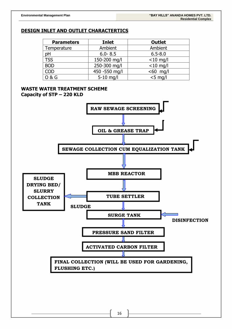
DESIGN INLET AND OUTLET CHARACTERTICS
Parameters Inlet Outlet
Temperature Ambient Ambient
pH 6.0- 8.5 6.5-8.0
TSS 150-200 mg/l <10 mg/l
BOD 250-300 mg/l <10 mg/l
COD 450 -550 mg/l <60 mg/l
O & G 5-10 mg/l <5 mg/l
WASTE WATER TREATMENT SCHEME Capacity of STP – 220 KLD
DISINFECTION
SLUDGE
RAW SEWAGE SCREENING
OIL & GREASE TRAP
SEWAGE COLLECTION CUM EQUALIZATION TANK
SURGE TANK
ACTIVATED CARBON FILTER
FINAL COLLECTION (WILL BE USED FOR GARDENING,
FLUSHING ETC.)
SLUDGE
DRYING BED/
SLURRY
COLLECTION
TANK
MBB REACTOR
TUBE SETTLER
PRESSURE SAND FILTER
Environmental Management Plan “BAY HILLS” ANANDA HOMES PVT. LTD. Residential Complex
17
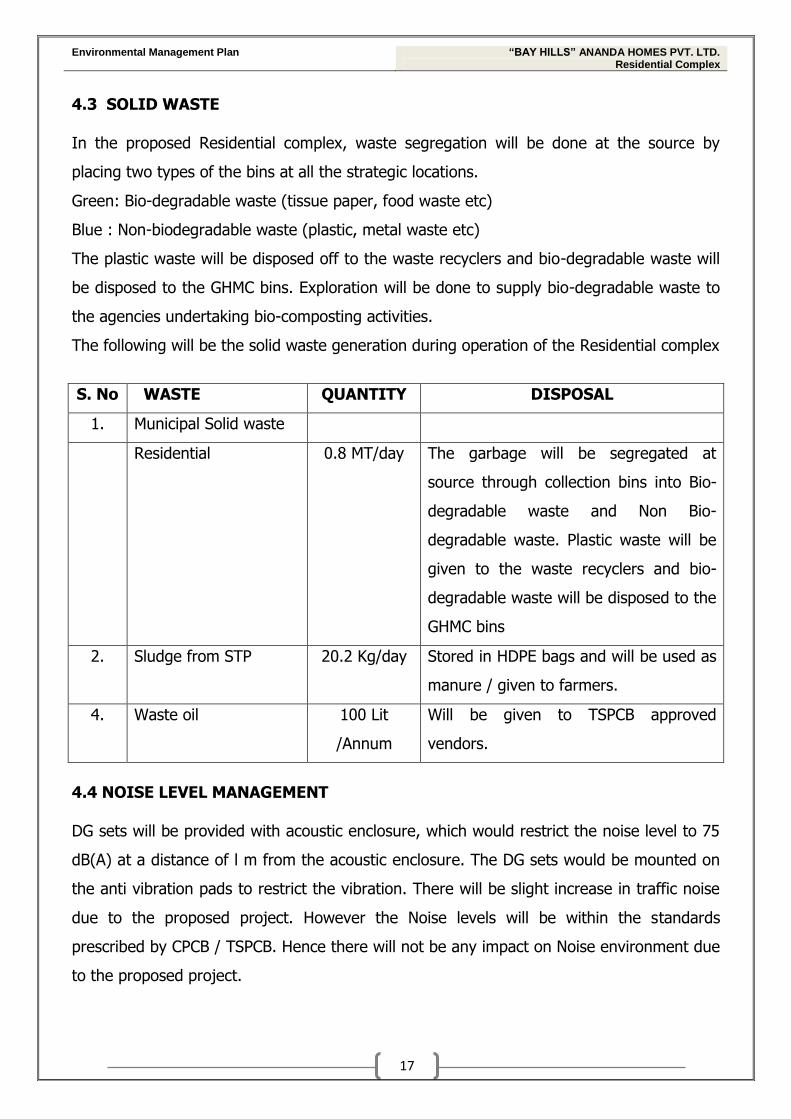
4.3 SOLID WASTE In the proposed Residential complex, waste segregation will be done at the source by
placing two types of the bins at all the strategic locations.
Green: Bio-degradable waste (tissue paper, food waste etc)
Blue : Non-biodegradable waste (plastic, metal waste etc)
The plastic waste will be disposed off to the waste recyclers and bio-degradable waste will
be disposed to the GHMC bins. Exploration will be done to supply bio-degradable waste to
the agencies undertaking bio-composting activities.
The following will be the solid waste generation during operation of the Residential complex
S. No WASTE QUANTITY DISPOSAL
1. Municipal Solid waste
Residential 0.8 MT/day
The garbage will be segregated at
source through collection bins into Bio-
degradable waste and Non Bio-
degradable waste. Plastic waste will be
given to the waste recyclers and bio-
degradable waste will be disposed to the
GHMC bins
2. Sludge from STP 20.2 Kg/day Stored in HDPE bags and will be used as
manure / given to farmers.
4. Waste oil 100 Lit
/Annum
Will be given to TSPCB approved
vendors.
4.4 NOISE LEVEL MANAGEMENT DG sets will be provided with acoustic enclosure, which would restrict the noise level to 75
dB(A) at a distance of l m from the acoustic enclosure. The DG sets would be mounted on
the anti vibration pads to restrict the vibration. There will be slight increase in traffic noise
due to the proposed project. However the Noise levels will be within the standards
prescribed by CPCB / TSPCB. Hence there will not be any impact on Noise environment due
to the proposed project.
Environmental Management Plan “BAY HILLS” ANANDA HOMES PVT. LTD. Residential Complex
18
4.5 LAND ENVIRONMENT
All the pavements in the site area will be grass paved, which will mitigate the dust
generation from the vehicles. Vehicle speed in the complex area will be reduced which will
reduce the emissions. Greenbelt will be developed in the complex area which will acts as
sink for the emissions.
Hence there will not be any deposition of pollutants in the surrounding area.
The sanitary waste water generated from the complex will be treated in STP with Fluidized
Aerobic Bio-reactor system. Treated waste water will be reused for non-potable purposes
like flushing and greenbelt development. Remaining treated waste water will be discharged
into the municipal drain
The solid waste generated from the complex will be disposed as per norms.
Hence there will not be any impact on land environment due to the proposed complex
Recommendations
a) Land scaping can be done periphery of the compound wall.
4.6 GREEN BELT DEVELOPMENT
Greenbelt will be developed all around the periphery of the compound wall along with some
part of the Greenbelt will be developed in Open spaces. The greenbelt will be developed
simultaneously with the plant construction. This will further mitigate the pollution impacts.
Greenbelt plantation
Greenbelt is developed in a set of rows of trees planted in such a way that they form an
effective barrier between the plant and the surroundings. The main purpose of greenbelt
development is to contribute to the following factors.
To maintain the ecological homeostatus.
To attenuate the dust emissions
To prevent the soil erosion.
To attenuate the noise levels.
To utilize the treated effluents.
Environmental Management Plan “BAY HILLS” ANANDA HOMES PVT. LTD. Residential Complex
19
Selection of species
The following main criteria will be followed for selection of plants:
• Trees, shrubs having dense foliage with a large surface area, as leaves absorb
pollutants.
• Evergreen trees as they are found to be more effective.
• The species resistant to pollutants, particularly in the early stages of their growth.
The following species are planned to be selected for greenbelt development in the complex
premises
Acacia arabica (Babul)
Citrus species
Dyospyros species
Ficus bengalensis (Banyan)
Ficus religiosa (Peepal)
Lillium spp. (Lily)
Polyathia lotigifolia (Ashok)
Tamarindus indica (Imli)
Thuja occidentallis (Cedar)
Prospis Juliflora (Mesquite)
Zizypus jujuba (jujuba), etc.
Greenbelt development plan
Green belt will be developed all around the complex area
Out of the total site area i.e. 2,225.6 Sq.m of area will be allocated for greenbelt
development
The tree species to be selected for the plantation are pollutant tolerant, fast
growing, wind firm, deep rooted.
4.7. RAINWATER HARVESTING
Rain Water from the various roofs will be drained through rain water vertical down take
uPVC pipes. These vertical down take pipes will be located at suitable locations inside the
shafts or embedded inside the wall. All the terraces will be sloped in a slope of 1:100
Environmental Management Plan “BAY HILLS” ANANDA HOMES PVT. LTD. Residential Complex
20
sloping towards down vertical pipes. Rain Water khurras will be of suitable size with MS/CI
grating provided at roof with each rain water vertical down take.
Rain water disposal will be designed as per NBC i.e. 150 mm dia covers the area 83.6 sq.m.
@ of 150mm/hour rain fall as per NBC.
Rain Water vertical down take of uPVC pipe will be left 75mm above the finished ground
level with elbow spouts. Under these spouts there will be a storm water catch basin so the
rainwater from the roofs will be discharged directly into the catch basin to avoid the
flooding into the surrounding areas. These catch basins will also be used for drainage of
the open surface surrounding the catch basin. There will be a catch basin along the
roadside to take care of the roadside storm water drainage. These catch basins will be
connected to the main storm water drainage system, which may be divided into two or
three parts to reduce the depth of the manhole as to suite the site conditions. The
discharge from these main drains will be discharged in to rain water-harvesting pits. These
pits will be located at different location to suite site conditions. The overflow from these
pits will be collected into an overflow sump. There will be a provision of submersible pump
in sump pit the overflow water from these pit pump out side or can be discharged directly
into existing storm water drain by gravity.
4.8 RISK ASSESSMENT AND MANAGEMENT PLAN FIRE PROTECTION SYSTEM
As per the provisions of the Telanagana state Fire Service Act, 1999, buildings of height
more than 18 m are required to obtain prior clearance from Telangana State Disasters
Response & Fire Services Department from fire safety point of view. For the proposed
building we will obtain NOC from Telangana State Disasters Response & Fire Services
Department.
DESIGN CRITERIA AND DESCRIPTION: Fire protection system will be designed and installed as per National Building Code
procedures.
Environmental Management Plan “BAY HILLS” ANANDA HOMES PVT. LTD. Residential Complex
21
HYDRANT SYSTEM (INTERNAL & EXTERNAL):
Water supply for hydrant system (Internal & External) is required to be capable of
providing the water pressure and flow characteristics required by systems being served.
External yard hydrants near to the face of the building with maximum spacing of 45 mts
between hydrant points.
Internal fire hydrant station consisting of landing valve and swinging type hose reel will
be provided at;
- All floors at every 1000 sq.m interval at each floor landing near the staircase.
PROPOSED DESIGN:
Fire Hydrant system (Internal & External): System will be hydraulically designed to provide
water flow at a minimum pressure of 3.5 Kg. / cm2 at the outlet of remotest hydrant valve.
Each hydrant station will comprise of single headed landing valve, swinging type hose reel
and other equipments.
Internal hydrants will be provided for every 1000sqm floor area at each floor landing near
the staircase.
The minimum flow rate will be 2280 lpm.
Internal hose connection and hose station will be unobstructed and will be located near the
Staircase, opening to the common area. The shaft size will be of 1.2mts x 1.2mts. The
hydrant riser will be terminated with air release valve at the highest point to release the
trapped air in the pipe network.
The External hydrants will be provided near the face of the building with the maximum
spacing of 45mts between two external hydrants.
The ring main in the ground level will be connected with internal hydrant system through
isolation valve and flow switches, also the external hydrant will be tapped from the same.
Four way Fire Brigade inlet connection at ground level at suitable location to fill the rising
mains of hydrant system, in case of failure of pumps.
Water storage capacity: 150,000 litres underground storage and 20,000 litres overhead
storage tanks will be provided as per NBC.
Environmental Management Plan “BAY HILLS” ANANDA HOMES PVT. LTD. Residential Complex
22
AUTOMATIC SPRINKLER SYSTEM:
The purpose of automatic sprinkler system is to control the growth and spread of fire to
provide increased protection to occupants and the building structure.
Code Requirements:
As per NBC- building has been classified, as Residential Buildings, Group-A.
Sprinkler isolation valve to have tamper proof alarm fitted.
After each flow switch, test drain to be provided.
Ceiling voids over 800mm to have sprinklers in upper layer.
In Guest rooms sidewall sprinklers to be extended coverage, quick response type.
Proposed Design:
The sprinkler system will be hydraulically designed in accordance with the above
requirement.
Minimum pressure: Note less than 20 psi (1.38 bars) for remotest sprinkler.
The sprinklers in the buildings will be fed from separate sprinkler riser located in the
internal FHCs. Each floor will be considered as separate zone to be annunciated separately
at Fire control room. The sprinklers piping network at each floor will be provide with
suitable size of butterfly valve with inbuilt supervisory switch, flow switch and test drain
assembly.
The sprinklers will be provided in all areas except in electrical room, transformer room and
switch room.
Isolation control valve (ICV) will be provided for sprinkler system at suitable location, for
alarming in case of fire.
Ball valves of suitable size will be provided for drain of sprinkler system at the farthest
point, and will be taken to nearest drain outlet by means of piping.
FIRE PUMPS:
Common electrical driven fire pumps for hydrant & sprinkler system and common jockey
pumps will be used for hydrant and sprinkler system. However the diesel engine driven for
both the system will be common with necessary reducing valve (if required) to compensate
the difference between operating pressure of both the systems.
Environmental Management Plan “BAY HILLS” ANANDA HOMES PVT. LTD. Residential Complex
23
The electrical pump will be of 2280 lpm at required head as per NBC 2005. The minimum
pressure required at the farthest and remotest hydrant valve is 3.5 Kg/ cm2 and pump head
is calculated accordingly.
Common jockey pump for both the systems will be of 180lpm at required head.
Common stand by diesel engine driven pumps for both the systems will be of 2280 lpm at
required head.
The jockey pump shut down will be automatic, whereas the main pumps and the diesel
engine for both the system will have manual shut down.
Fire pump test connection with flow measuring station will be provided with piping to re-
circulate the pump's discharge to water supply tank or to the pump suction.
Following is the configuration of fire pumps proposed;
a) One common Electrical driven pump for Hydrant and sprinkler systems.
b) One common stand by diesel driven pump for hydrant & sprinkler system
c) Common jockey pump
SYSTEM OPERATION:
When the sprinkler head, hydrant valve or hose reel opens, the pressure drop in respective
piping network which will be sensed by pressure switches installed on delivery header of
pumping system. This in turn switches on the jockey pump automatically to meet the
water requirement. In case of further drop, the main pump will start automatically to meet
the water requirement. The jockey pump will start and shut down automatically as per
pressure gauge settings, whereas the main pump common for both the systems and the
diesel engine driven pump will start automatically but shut down has to be done manually.
PORTABLE FIRE EXTINGUISHERS:
Proposed Design
Hand held fire extinguishers will be located as per NBC-2005 and will be located adjacent to
fire hose reel cabinet. The fire extinguishers will be designed based on the requirement of
Local authority.
Portable fire extinguishers will be provided at the locations mentioned below;
Environmental Management Plan “BAY HILLS” ANANDA HOMES PVT. LTD. Residential Complex
24
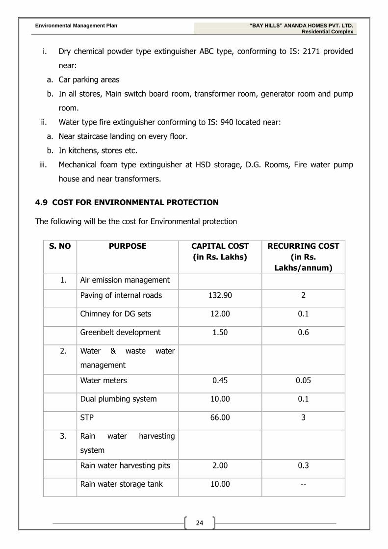
i. Dry chemical powder type extinguisher ABC type, conforming to IS: 2171 provided
near:
a. Car parking areas
b. In all stores, Main switch board room, transformer room, generator room and pump
room.
ii. Water type fire extinguisher conforming to IS: 940 located near:
a. Near staircase landing on every floor.
b. In kitchens, stores etc.
iii. Mechanical foam type extinguisher at HSD storage, D.G. Rooms, Fire water pump
house and near transformers.
4.9 COST FOR ENVIRONMENTAL PROTECTION
The following will be the cost for Environmental protection
S. NO PURPOSE CAPITAL COST
(in Rs. Lakhs)
RECURRING COST
(in Rs.
Lakhs/annum)
1. Air emission management
Paving of internal roads 132.90 2
Chimney for DG sets 12.00 0.1
Greenbelt development 1.50 0.6
2. Water & waste water
management
Water meters 0.45 0.05
Dual plumbing system 10.00 0.1
STP 66.00 3
3. Rain water harvesting
system
Rain water harvesting pits 2.00 0.3
Rain water storage tank 10.00 --
Environmental Management Plan “BAY HILLS” ANANDA HOMES PVT. LTD. Residential Complex
25
S. NO PURPOSE CAPITAL COST
(in Rs. Lakhs)
RECURRING COST
(in Rs.
Lakhs/annum)
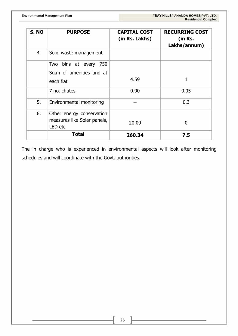
4. Solid waste management
Two bins at every 750
Sq.m of amenities and at
each flat 4.59 1
7 no. chutes 0.90 0.05
5. Environmental monitoring -- 0.3
6. Other energy conservation
measures like Solar panels,
LED etc 20.00 0
Total 260.34 7.5
The in charge who is experienced in environmental aspects will look after monitoring
schedules and will coordinate with the Govt. authorities.
Environmental Management Plan “BAY HILLS” ANANDA HOMES PVT. LTD. Residential Complex
26
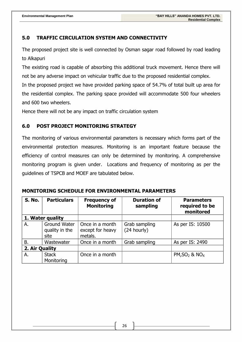
5.0 TRAFFIC CIRCULATION SYSTEM AND CONNECTIVITY
The proposed project site is well connected by Osman sagar road followed by road leading
to Alkapuri
The existing road is capable of absorbing this additional truck movement. Hence there will
not be any adverse impact on vehicular traffic due to the proposed residential complex.
In the proposed project we have provided parking space of 54.7% of total built up area for
the residential complex. The parking space provided will accommodate 500 four wheelers
and 600 two wheelers.
Hence there will not be any impact on traffic circulation system
6.0 POST PROJECT MONITORING STRATEGY
The monitoring of various environmental parameters is necessary which forms part of the
environmental protection measures. Monitoring is an important feature because the
efficiency of control measures can only be determined by monitoring. A comprehensive
monitoring program is given under. Locations and frequency of monitoring as per the
guidelines of TSPCB and MOEF are tabulated below.
MONITORING SCHEDULE FOR ENVIRONMENTAL PARAMETERS
S. No. Particulars Frequency of Monitoring
Duration of sampling
Parameters required to be
monitored
1. Water quality
A. Ground Water quality in the site
Once in a month except for heavy metals.
Grab sampling (24 hourly)
As per IS: 10500
B. Wastewater Once in a month Grab sampling As per IS: 2490
2. Air Quality
A. Stack Monitoring
Once in a month PM,SO2 & NOX
Environmental Management Plan “BAY HILLS” ANANDA HOMES PVT. LTD. Residential Complex
27
CONCLUSIONS
1. Dust curtains will be used to reduce the dust emissions during construction of proposed
project.
2. The flue gases from the D.G. Set will be let out through a stack of adequate height for
effective dispersion of emissions into the atmosphere. The resultant Ground Level
Concentrations of PM, CO & NOX in the post project scenario are within the National
Ambient Air Quality Standards (NAAQS). Hence there will not be any adverse impact on
air environment due to the proposed project.
3. All Driveways & internal roads will be grass paved.
4. Wastewater generated from the apartment will be treated in sewage treatment plant
and will be utilized for non-potable purposes like Toilet flushing & gardening.
5. Rain Water Harvesting pits will be provided to augment the precious rain water and
ground water recharge
6. The Solid waste in the form of garbage will be segregated at source into bio-degradable
and non-bio-degradable waste. Plastic waste will be given to the authorized recyclers
and bio-degradable waste will be sent to GHMC.
7. Greenbelt of 2,225.6 Sq.m will be developed all around the project site and in the open
area
8. Adequate firefighting equipment’s will be implemented as per the, etc. as per National
Building Code.