Embed Size (px)
Citation preview

maxon motor ag Brünigstrasse 220 P.O.Box 263 CH-6072 Sachseln Phone +41 (41) 666 15 00 Fax +41 (41) 666 16 50 www.maxonmotor.com
Edition March 2011
EPOS2 Positioning Controller
Hardware Reference
maxon motor control
24/5Positioning Controller
Hardware Reference
Document ID: rel2400

maxon motor controlA-2 Document ID: rel2400 EPOS2 Positioning Controller
Edition: March 2011 EPOS2 24/5 Hardware Reference© 2011 maxon motor. Subject to change without prior notice.
PLEASE READ THIS FIRST
These instructions are intended for qualified technical personnel. Prior commencing with anyactivities …• you must carefully read and understand this manual and• you must follow the instructions given therein.
We have tried to provide you with all information necessary to install and commission the equipment in a secure, safe and time-saving manner. Our main focus is …
• to familiarize you with all relevant technical aspects,
• to let you know the easiest way of doing,
• to alert you of any possibly dangerous situation you might encounter or that you might cause if you do not follow the description,
• to write as little and to say as much as possible and
• not to bore you with things you already know.
Likewise, we tried to skip repetitive information! Thus, you will find things mentioned just once. If, for example, an earlier mentioned action fits other occasions you then will be directed to that text passage with a respective reference.
Follow any stated reference – observe respective information – then go back and continue withthe task!
PREREQUISITES FOR PERMISSION TO COMMENCE INSTALLATION
The EPOS2 24/5 is considered as partly completed machinery according to EU’s directive 2006/42/EC, Article 2, Clause (g) and therefore is intended to be incorporated into or assembled with other machinery or other partly completed machinery or equipment.
You must not put the device into service, …• unless you have made completely sure that the other machinery – the surrounding system the device
is intended to be incorporated to – fully complies with the requirements stated in the EU directive 2006/42/EC!
• unless the surrounding system fulfills all relevant health and safety aspects!• unless all respective interfaces have been established and fulfill the stated requirements!

maxon motor controlEPOS2 Positioning Controller Document ID: rel2400 A-3EPOS2 24/5 Hardware Reference Edition: March 2011
© 2011 maxon motor. Subject to change without prior notice.
1 About this Document 5
2 Introduction 9
2.1 Documentation Structure . . . . . . . . . . . . . . . . . . . . . . . . . . . . . . . . . . . . . . . . . 9
2.2 Safety Precautions. . . . . . . . . . . . . . . . . . . . . . . . . . . . . . . . . . . . . . . . . . . . . 10
3 Technical Data 11
3.1 Electrical Data . . . . . . . . . . . . . . . . . . . . . . . . . . . . . . . . . . . . . . . . . . . . . . . . 11
3.2 Mechanical Data . . . . . . . . . . . . . . . . . . . . . . . . . . . . . . . . . . . . . . . . . . . . . . 14
3.3 Environmental Conditions . . . . . . . . . . . . . . . . . . . . . . . . . . . . . . . . . . . . . . . 14
3.4 Order Details . . . . . . . . . . . . . . . . . . . . . . . . . . . . . . . . . . . . . . . . . . . . . . . . . 14
4 Connections 15
4.1 Power Supply Connector (J1) . . . . . . . . . . . . . . . . . . . . . . . . . . . . . . . . . . . . 164.1.1 Determination of Power Supply . . . . . . . . . . . . . . . . . . . . . . . . . . . . . . . . . . . . . . . . . . . 16
4.1.2 Use of separate Logic Supply . . . . . . . . . . . . . . . . . . . . . . . . . . . . . . . . . . . . . . . . . . . . 17
4.2 Motor Connector (J2). . . . . . . . . . . . . . . . . . . . . . . . . . . . . . . . . . . . . . . . . . . 184.2.1 maxon EC motor (brushless) . . . . . . . . . . . . . . . . . . . . . . . . . . . . . . . . . . . . . . . . . . . . . 18
4.2.2 maxon DC motor with separated Motor/Encoder Cable. . . . . . . . . . . . . . . . . . . . . . . . . 18
4.2.3 maxon DC motor with integrated Motor/Encoder Ribbon Cable . . . . . . . . . . . . . . . . . . 19
4.3 Hall Sensor Connector (J3) . . . . . . . . . . . . . . . . . . . . . . . . . . . . . . . . . . . . . . 20
4.4 Encoder Connector (J4). . . . . . . . . . . . . . . . . . . . . . . . . . . . . . . . . . . . . . . . . 21
4.5 Signal Connector (J5) . . . . . . . . . . . . . . . . . . . . . . . . . . . . . . . . . . . . . . . . . . 234.5.1 Digital Inputs 1, 2 and 3 . . . . . . . . . . . . . . . . . . . . . . . . . . . . . . . . . . . . . . . . . . . . . . . . . 24
4.5.2 Digital Inputs 4, 5 and 6 . . . . . . . . . . . . . . . . . . . . . . . . . . . . . . . . . . . . . . . . . . . . . . . . . 25
4.5.3 Analog Inputs 1 and 2 . . . . . . . . . . . . . . . . . . . . . . . . . . . . . . . . . . . . . . . . . . . . . . . . . . 27
4.5.4 Auxiliary Supply Voltage Output . . . . . . . . . . . . . . . . . . . . . . . . . . . . . . . . . . . . . . . . . . 27
4.5.5 Digital Outputs 1, 2 and 3 . . . . . . . . . . . . . . . . . . . . . . . . . . . . . . . . . . . . . . . . . . . . . . . 28
4.5.6 Digital Output 4 . . . . . . . . . . . . . . . . . . . . . . . . . . . . . . . . . . . . . . . . . . . . . . . . . . . . . . . 29
4.6 RS232 Connector (J6) . . . . . . . . . . . . . . . . . . . . . . . . . . . . . . . . . . . . . . . . . . 30
4.7 CAN Connector (J7, J8). . . . . . . . . . . . . . . . . . . . . . . . . . . . . . . . . . . . . . . . . 31
4.8 CAN Configuration (JP1) . . . . . . . . . . . . . . . . . . . . . . . . . . . . . . . . . . . . . . . . 324.8.1 CAN ID (Node Address). . . . . . . . . . . . . . . . . . . . . . . . . . . . . . . . . . . . . . . . . . . . . . . . . 32
4.8.2 CAN Bus Termination . . . . . . . . . . . . . . . . . . . . . . . . . . . . . . . . . . . . . . . . . . . . . . . . . . 33
4.9 USB Connector (J9). . . . . . . . . . . . . . . . . . . . . . . . . . . . . . . . . . . . . . . . . . . . 34
4.10 Status LEDs. . . . . . . . . . . . . . . . . . . . . . . . . . . . . . . . . . . . . . . . . . . . . . . . . . 35
TABLE OF CONTENTS

maxon motor controlA-4 Document ID: rel2400 EPOS2 Positioning Controller
Edition: March 2011 EPOS2 24/5 Hardware Reference© 2011 maxon motor. Subject to change without prior notice.
• • p a g e i n t e n t i o n a l l y l e f t b l a n k • •
maxon motor controlEPOS2 Positioning Controller Document ID: rel2400 1-5EPOS2 24/5 Hardware Reference Edition: March 2011
© 2011 maxon motor. Subject to change without prior notice.
1 About this Document
1.1 Intended PurposeThe purpose of the present document is to familiarize you with the described equipment and the tasks on safe and adequate installation and/or commissioning.
Observing the described instructions in this document will help you …
• to avoid dangerous situations,
• to keep installation and/or commissioning time at a minimum and
• to increase reliability and service life of the described equipment.
Use for other and/or additional purposes is not permitted. maxon motor, the manufacturer of the equip-ment described, does not assume any liability for loss or damage that may arise from any other and/or additional use than the intended purpose.
1.2 Target AudienceThis document is meant for trained and skilled personnel working with the equipment described. It con-veys information on how to understand and fulfill the respective work and duties.
This document is a reference book. It does require particular knowledge and expertise specific to the equipment described.
1.3 How to useTake note of the following notations and codes which will be used throughout the document.
Table 1-1 Notations used in this Document
1.4 Symbols and Signs
1.4.1 Safety Alerts
Take note of when and why the alerts will be used and what the consequences are if you shouldfail to observe them!
Safety alerts are composed of…
• a signal word,
• a description of type and/or source of the danger,
• the consequence if the alert is being ignored, and
• explanations on how to avoid the hazard.
Following types will be used:
1) DANGERIndicates an imminently hazardous situation. If not avoided, the situation will result in death or serious injury.
2) WARNINGIndicates a potentially hazardous situation. If not avoided, the situation can result in death or serious injury.
Notation Explanation
(n) referring to an item (such as order number, list item, etc.)
denotes “see”, “see also”, “take note of” or “go to”

maxon motor control1-6 Document ID: rel2400 EPOS2 Positioning Controller
Edition: March 2011 EPOS2 24/5 Hardware Reference© 2011 maxon motor. Subject to change without prior notice.
3) CAUTIONIndicates a probable hazardous situation and is also used to alert against unsafe practices. If not avoided, the situation may result in minor or moderate injury.
Example:
1.4.2 Prohibited Actions and Mandatory Actions
The signs define prohibitive actions. So, you must not!
Examples:
The signs point out actions to avoid a hazard. So, you must!
Examples:
1.4.3 Informatory Signs
Requirement / Note / RemarkIndicates an action you must perform prior continuing or refers to information on a particular item.
Best PracticeGives advice on the easiest and best way to proceed.
Material DamagePoints out information particular to potential damage of equipment.
ReferenceRefers to particular information provided by other parties.
DANGER
High Voltage and/or Electrical ShockTouching live wires causes death or serious injuries!• Make sure that neither end of cable is connected to life power!• Make sure that power source cannot be engaged while work is in process!• Obey lock-out/tag-out procedures!• Make sure to securely lock any power engaging equipment against unintentional engagement and
tag with your name!
Do not touch! Do not operate!
Unplug! Tag before work!
maxon motor controlEPOS2 Positioning Controller Document ID: rel2400 1-7EPOS2 24/5 Hardware Reference Edition: March 2011
© 2011 maxon motor. Subject to change without prior notice.
1.5 Trademarks and Brand NamesFor easier legibility, registered brand names are listed below and will not be further tagged with their respective trademark. It must be understood that the brands (the below list is not necessarily conclud-ing) are protected by copyright and/or other intellectual property rights even if their legal trademarks are omitted in the later course of this document.
Table 1-2 Brand Names and Trademark Owners
1.6 Copyright© 2011 maxon motor. All rights reserved.
The present document – including all parts thereof – is protected by copyright. Any use (including repro-duction, translation, microfilming and other means of electronic data processing) beyond the narrow restrictions of the copyright law without the prior approval of maxon motor ag, is not permitted and sub-ject to persecution under the applicable law.
maxon motor agBrünigstrasse 220P.O.Box 263CH-6072 SachselnSwitzerland
Phone +41 (41) 666 15 00Fax +41 (41) 666 16 50
www.maxonmotor.com
The brand name(s) … … is/are a registered trademark(s) of …
Adobe® Reader® © Adobe Systems Incorporated, USA-San Jose, CA
Micro-Fit™Mini-Fit Jr.™
© Molex, USA-Lisle, IL
Pentium® © Intel Corporation, USA-Santa Clara, CA
Windows® © Microsoft Corporation, USA-Redmond, WA

maxon motor control1-8 Document ID: rel2400 EPOS2 Positioning Controller
Edition: March 2011 EPOS2 24/5 Hardware Reference© 2011 maxon motor. Subject to change without prior notice.
• • p a g e i n t e n t i o n a l l y l e f t b l a n k • •
maxon motor controlEPOS2 Positioning Controller Document ID: rel2400 2-9EPOS2 24/5 Hardware Reference Edition: March 2011
© 2011 maxon motor. Subject to change without prior notice.
2 Introduction
The present document provides you with information on the EPOS2 24/5 Positioning Controller’s hard-ware. It contains…
• performance data and specifications,
• information on connections and pin assignment and
• wiring examples.
maxon motor control’s EPOS2 24/5 is a small-sized, full digital, smart motion controller. Due to its flexi-ble and high efficient power stage, the EPOS2 24/5 drives brushed DC motors with digital encoder as well as brushless EC motors with digital Hall sensors and encoder.
The sinusoidal current commutation by space vector control offers the possibility to drive brushless EC motors with minimal torque ripple and low noise. The integrated position, velocity and current control functionality allows sophisticated positioning applications. The EPOS2 24/5 is especially designed being commanded and controlled as a slave node in a CANopen network. In addition, the unit can be operated via any USB or RS232 interface.
Find the latest edition of the present document, as well as additional documentation and software to the EPOS2 24/5 Positioning Controller also on the internet:
www.maxonmotor.com – category «Service & Downloads»
shop.maxonmotor.com
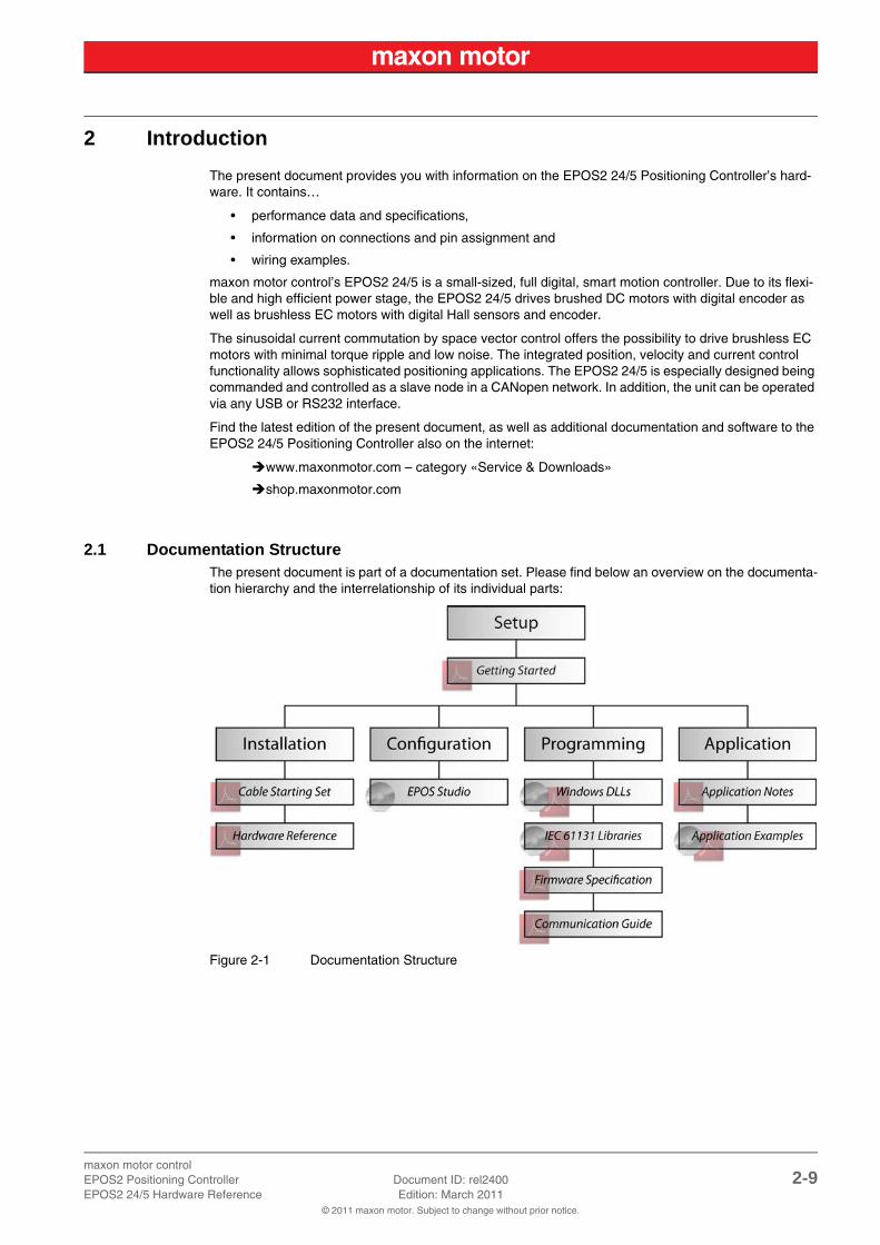
2.1 Documentation StructureThe present document is part of a documentation set. Please find below an overview on the documenta-tion hierarchy and the interrelationship of its individual parts:
Figure 2-1 Documentation Structure
maxon motor control2-10 Document ID: rel2400 EPOS2 Positioning Controller
Edition: March 2011 EPOS2 24/5 Hardware Reference© 2011 maxon motor. Subject to change without prior notice.
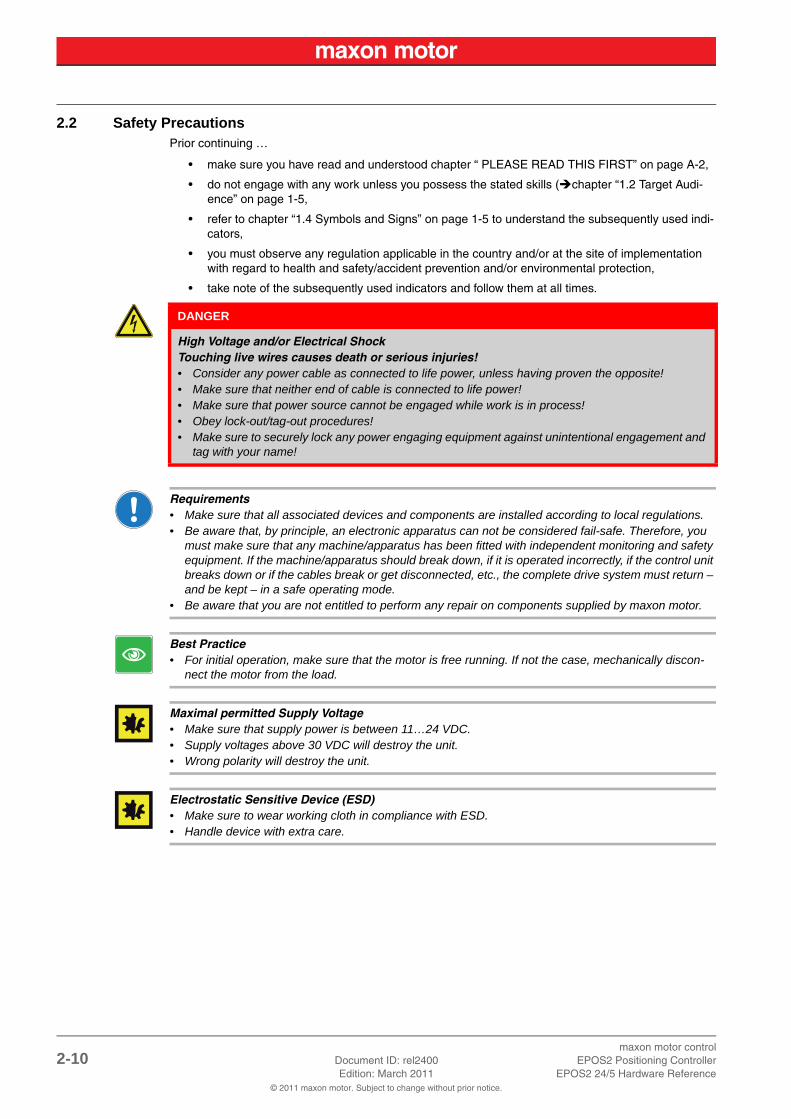
2.2 Safety PrecautionsPrior continuing …
• make sure you have read and understood chapter “ PLEASE READ THIS FIRST” on page A-2,
• do not engage with any work unless you possess the stated skills (chapter “1.2 Target Audi-ence” on page 1-5,
• refer to chapter “1.4 Symbols and Signs” on page 1-5 to understand the subsequently used indi-cators,
• you must observe any regulation applicable in the country and/or at the site of implementation with regard to health and safety/accident prevention and/or environmental protection,
• take note of the subsequently used indicators and follow them at all times.
Requirements• Make sure that all associated devices and components are installed according to local regulations.• Be aware that, by principle, an electronic apparatus can not be considered fail-safe. Therefore, you
must make sure that any machine/apparatus has been fitted with independent monitoring and safety equipment. If the machine/apparatus should break down, if it is operated incorrectly, if the control unit breaks down or if the cables break or get disconnected, etc., the complete drive system must return – and be kept – in a safe operating mode.
• Be aware that you are not entitled to perform any repair on components supplied by maxon motor.
Best Practice• For initial operation, make sure that the motor is free running. If not the case, mechanically discon-
nect the motor from the load.
Maximal permitted Supply Voltage• Make sure that supply power is between 11…24 VDC.• Supply voltages above 30 VDC will destroy the unit.• Wrong polarity will destroy the unit.
Electrostatic Sensitive Device (ESD)• Make sure to wear working cloth in compliance with ESD.• Handle device with extra care.
DANGER
High Voltage and/or Electrical ShockTouching live wires causes death or serious injuries!• Consider any power cable as connected to life power, unless having proven the opposite!• Make sure that neither end of cable is connected to life power!• Make sure that power source cannot be engaged while work is in process!• Obey lock-out/tag-out procedures!• Make sure to securely lock any power engaging equipment against unintentional engagement and
tag with your name!
maxon motor controlEPOS2 Positioning Controller Document ID: rel2400 3-11EPOS2 24/5 Hardware Reference Edition: March 2011
© 2011 maxon motor. Subject to change without prior notice.
3 Technical Data
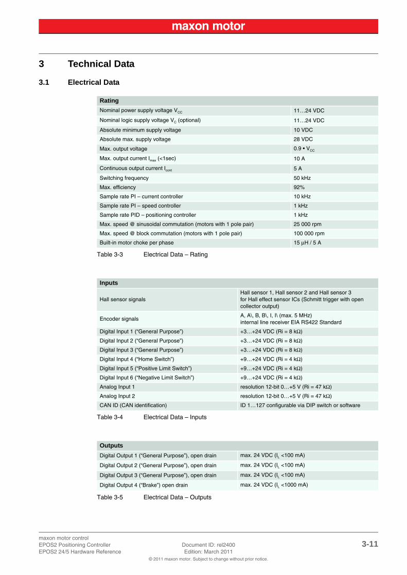
3.1 Electrical Data
Table 3-3 Electrical Data – Rating
Table 3-4 Electrical Data – Inputs
Table 3-5 Electrical Data – Outputs
Rating
Nominal power supply voltage VCC 11…24 VDC
Nominal logic supply voltage VC (optional) 11…24 VDC
Absolute minimum supply voltage 10 VDC
Absolute max. supply voltage 28 VDC
Max. output voltage 0.9 • VCC
Max. output current Imax (<1sec) 10 A
Continuous output current Icont 5 A
Switching frequency 50 kHz
Max. efficiency 92%
Sample rate PI – current controller 10 kHz
Sample rate PI – speed controller 1 kHz
Sample rate PID – positioning controller 1 kHz
Max. speed @ sinusoidal commutation (motors with 1 pole pair) 25 000 rpm
Max. speed @ block commutation (motors with 1 pole pair) 100 000 rpm
Built-in motor choke per phase 15 μH / 5 A
Inputs
Hall sensor signalsHall sensor 1, Hall sensor 2 and Hall sensor 3for Hall effect sensor ICs (Schmitt trigger with open collector output)
Encoder signalsA, A\, B, B\, I, I\ (max. 5 MHz)internal line receiver EIA RS422 Standard
Digital Input 1 (“General Purpose”) +3…+24 VDC (Ri = 8 kΩ)
Digital Input 2 (“General Purpose”) +3…+24 VDC (Ri = 8 kΩ)
Digital Input 3 (“General Purpose”) +3…+24 VDC (Ri = 8 kΩ)
Digital Input 4 (“Home Switch”) +9…+24 VDC (Ri = 4 kΩ)
Digital Input 5 (“Positive Limit Switch”) +9…+24 VDC (Ri = 4 kΩ)
Digital Input 6 (“Negative Limit Switch”) +9…+24 VDC (Ri = 4 kΩ)
Analog Input 1 resolution 12-bit 0…+5 V (Ri = 47 kΩ)
Analog Input 2 resolution 12-bit 0…+5 V (Ri = 47 kΩ)
CAN ID (CAN identification) ID 1…127 configurable via DIP switch or software
Outputs
Digital Output 1 (“General Purpose”), open drain max. 24 VDC (IL <100 mA)
Digital Output 2 (“General Purpose”), open drain max. 24 VDC (IL <100 mA)
Digital Output 3 (“General Purpose”), open drain max. 24 VDC (IL <100 mA)
Digital Output 4 (“Brake”) open drain max. 24 VDC (IL <1000 mA)

maxon motor control3-12 Document ID: rel2400 EPOS2 Positioning Controller
Edition: March 2011 EPOS2 24/5 Hardware Reference© 2011 maxon motor. Subject to change without prior notice.
Table 3-6 Electrical Data – Voltage Outputs
Table 3-7 Electrical Data – Motor Connections
Table 3-8 Electrical Data – Interfaces
Table 3-9 Electrical Data – LEDs
Voltage Outputs
Encoder supply voltage +5 VDC (IL <100 mA)
Hall sensors supply voltage +5 VDC (IL <30 mA)
Auxiliary output voltage Vcc (IL <1300 mA)
Motor Connections
maxon EC motor maxon DC motor
Motor winding 1 + Motor
Motor winding 2 - Motor
Motor winding 3
Interfaces
RS232 RxD; TxD max. 115 200 bit/s
USB 2.0 Data+; Data- max.12 Mbit/s
CAN 1 CAN_H (high); CAN_L (low) max.1 Mbit/s
CAN 2 CAN_H (high); CAN_L (low) max.1 Mbit/s
Status Indicators
Operation green LED
Error red LED
maxon motor controlEPOS2 Positioning Controller Document ID: rel2400 3-13EPOS2 24/5 Hardware Reference Edition: March 2011
© 2011 maxon motor. Subject to change without prior notice.
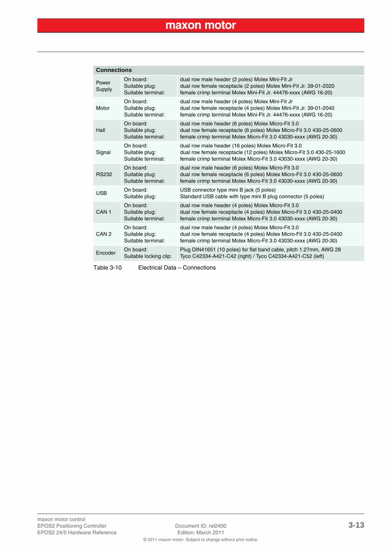
Table 3-10 Electrical Data – Connections
Connections
PowerSupply
On board:Suitable plug:Suitable terminal:
dual row male header (2 poles) Molex Mini-Fit Jrdual row female receptacle (2 poles) Molex Mini-Fit Jr. 39-01-2020female crimp terminal Molex Mini-Fit Jr. 44476-xxxx (AWG 16-20)
MotorOn board:Suitable plug:Suitable terminal:
dual row male header (4 poles) Molex Mini-Fit Jrdual row female receptacle (4 poles) Molex Mini-Fit Jr. 39-01-2040female crimp terminal Molex Mini-Fit Jr. 44476-xxxx (AWG 16-20)
HallOn board:Suitable plug:Suitable terminal:
dual row male header (6 poles) Molex Micro-Fit 3.0dual row female receptacle (6 poles) Molex Micro-Fit 3.0 430-25-0600female crimp terminal Molex Micro-Fit 3.0 43030-xxxx (AWG 20-30)
SignalOn board:Suitable plug:Suitable terminal:
dual row male header (16 poles) Molex Micro-Fit 3.0dual row female receptacle (12 poles) Molex Micro-Fit 3.0 430-25-1600female crimp terminal Molex Micro-Fit 3.0 43030-xxxx (AWG 20-30)
RS232On board:Suitable plug:Suitable terminal:
dual row male header (6 poles) Molex Micro-Fit 3.0dual row female receptacle (6 poles) Molex Micro-Fit 3.0 430-25-0600female crimp terminal Molex Micro-Fit 3.0 43030-xxxx (AWG 20-30)
USBOn board:Suitable plug:
USB connector type mini B jack (5 poles)Standard USB cable with type mini B plug connector (5 poles)
CAN 1On board:Suitable plug:Suitable terminal:
dual row male header (4 poles) Molex Micro-Fit 3.0dual row female receptacle (4 poles) Molex Micro-Fit 3.0 430-25-0400female crimp terminal Molex Micro-Fit 3.0 43030-xxxx (AWG 20-30)
CAN 2On board:Suitable plug:Suitable terminal:
dual row male header (4 poles) Molex Micro-Fit 3.0dual row female receptacle (4 poles) Molex Micro-Fit 3.0 430-25-0400female crimp terminal Molex Micro-Fit 3.0 43030-xxxx (AWG 20-30)
EncoderOn board:Suitable locking clip:
Plug DIN41651 (10 poles) for flat band cable, pitch 1.27mm, AWG 28Tyco C42334-A421-C42 (right) / Tyco C42334-A421-C52 (left)

maxon motor control3-14 Document ID: rel2400 EPOS2 Positioning Controller
Edition: March 2011 EPOS2 24/5 Hardware Reference© 2011 maxon motor. Subject to change without prior notice.
3.2 Mechanical Data
Table 3-11 Mechanical Data
Figure 3-2 Dimensional Drawing [mm]
3.3 Environmental Conditions
Table 3-12 Environmental Conditions
3.4 Order Details
Table 3-13 Order Details
Mechanical Data
Weight approx. 170 g
Dimensions (L x W x H) 105 x 83 x 24 mm
Mounting plate for M3 screws
Environmental Condition
Temperature (operation / storage) -10…+45°C / -40…+85°C
Humidity 20…80% (condensation not permitted)
Order Details
EPOS2 24/5 Order number 367676
maxon motor controlEPOS2 Positioning Controller Document ID: rel2400 4-15EPOS2 24/5 Hardware Reference Edition: March 2011
© 2011 maxon motor. Subject to change without prior notice.
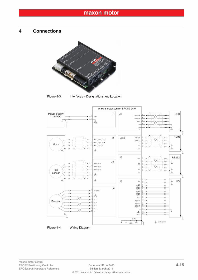
4 Connections
Figure 4-3 Interfaces – Designations and Location
Figure 4-4 Wiring Diagram
maxon motor control4-16 Document ID: rel2400 EPOS2 Positioning Controller
Edition: March 2011 EPOS2 24/5 Hardware Reference© 2011 maxon motor. Subject to change without prior notice.
4.1 Power Supply Connector (J1)
Best PracticeKeep the motor mechanically disconnected during setup and adjustment phase.
4.1.1 Determination of Power Supply
Basically, any power supply may be used, provided it meets below stated minimal requirements.
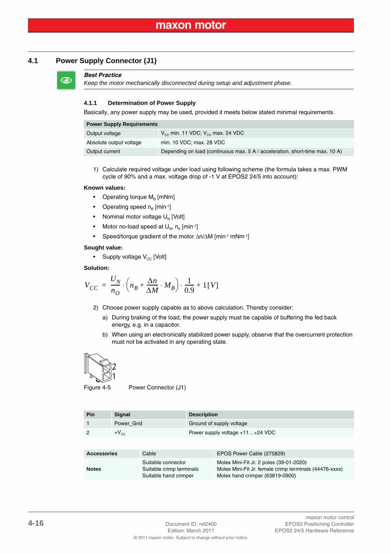
1) Calculate required voltage under load using following scheme (the formula takes a max. PWM cycle of 90% and a max. voltage drop of -1 V at EPOS2 24/5 into account):
Known values:
• Operating torque MB [mNm]
• Operating speed nB [min-1]
• Nominal motor voltage UN [Volt]
• Motor no-load speed at UN, n0 [min-1]
• Speed/torque gradient of the motor Δn/ΔM [min-1 mNm-1]
Sought value:
• Supply voltage VCC [Volt]
Solution:
2) Choose power supply capable as to above calculation. Thereby consider:
a) During braking of the load, the power supply must be capable of buffering the fed back energy, e.g. in a capacitor.
b) When using an electronically stabilized power supply, observe that the overcurrent protection must not be activated in any operating state.
Figure 4-5 Power Connector (J1)
Power Supply Requirements
Output voltage VCC min. 11 VDC; VCC max. 24 VDC
Absolute output voltage min. 10 VDC; max. 28 VDC
Output current Depending on load (continuous max. 5 A / acceleration, short-time max. 10 A)
Pin Signal Description
1 Power_Gnd Ground of supply voltage
2 +VCC Power supply voltage +11…+24 VDC
Accessories Cable EPOS Power Cable (275829)
NotesSuitable connectorSuitable crimp terminalsSuitable hand crimper
Molex Mini-Fit Jr. 2 poles (39-01-2020)Molex Mini-Fit Jr. female crimp terminals (44476-xxxx)Molex hand crimper (63819-0900)
VCCUNnO------- nB
ΔnΔM--------- MB⋅+
10.9-------⋅⋅ 1 V[ ]+=

maxon motor controlEPOS2 Positioning Controller Document ID: rel2400 4-17EPOS2 24/5 Hardware Reference Edition: March 2011
© 2011 maxon motor. Subject to change without prior notice.
4.1.2 Use of separate Logic Supply
By default, the logic is powered by the regular supply voltage. Optionally, you may wish to feed the logic supply voltage separately, permitting a safe and economical power backup feature.
Basically, any power supply may be used, provided it meets below stated minimal requirements.
Using a separate logic supply, you will need to change the jumper JP4.
STOP!Check on safety precautions before continuing (page 2-10).
1) Open housing and find jumper JP4.
2) Open jumper JP4 (Figure 4-7, right).
3) Connect to respective supply voltage (chapter “4.5 Signal Connector (J5)” on page 4-23).
Figure 4-6 Jumper JP4 – Location and Factory Setting
Figure 4-7 Jumper JP4 – closed (left) / open (right)
Logic Power Supply Requirements
Output voltage VC min. 11 VDC; VC max. 24 VDC
Absolute output voltage min. 10 VDC; max. 28 VDC
Min. output power PC min. 3 W

maxon motor control4-18 Document ID: rel2400 EPOS2 Positioning Controller
Edition: March 2011 EPOS2 24/5 Hardware Reference© 2011 maxon motor. Subject to change without prior notice.
4.2 Motor Connector (J2)By default, the controller is set to drive either maxon EC motor (brushless) or maxon DC motor (brushed) with separated motor/encoder cable. Using a maxon DC motor with integrated motor/encoder ribbon cable, you will need to change the jumpers JP2 and JP3.
Figure 4-8 Motor Connector (J2)
4.2.1 maxon EC motor (brushless)
4.2.2 maxon DC motor with separated Motor/Encoder Cable
Accessories Cable EPOS Motor Cable (275851)
NotesSuitable connectorSuitable crimp terminalsSuitable hand crimper
Molex Mini-Fit Jr. 4 poles (39-01-2040)Molex Mini-Fit Jr. female crimp terminals (44476-xxxx)Molex hand crimper (63819-0900)
Pin Signal Description
1 Motor winding 1 EC motor: Winding 1
2 Motor winding 2 EC motor: Winding 2
3 Motor winding 3 EC motor: Winding 3
4 Motor shield Cable shield
Pin Signal Description
1 Motor (+M) DC motor: Motor +
2 Motor (-M) DC motor: Motor -
3 do not connect
4 Motor shield Cable shield
maxon motor controlEPOS2 Positioning Controller Document ID: rel2400 4-19EPOS2 24/5 Hardware Reference Edition: March 2011
© 2011 maxon motor. Subject to change without prior notice.
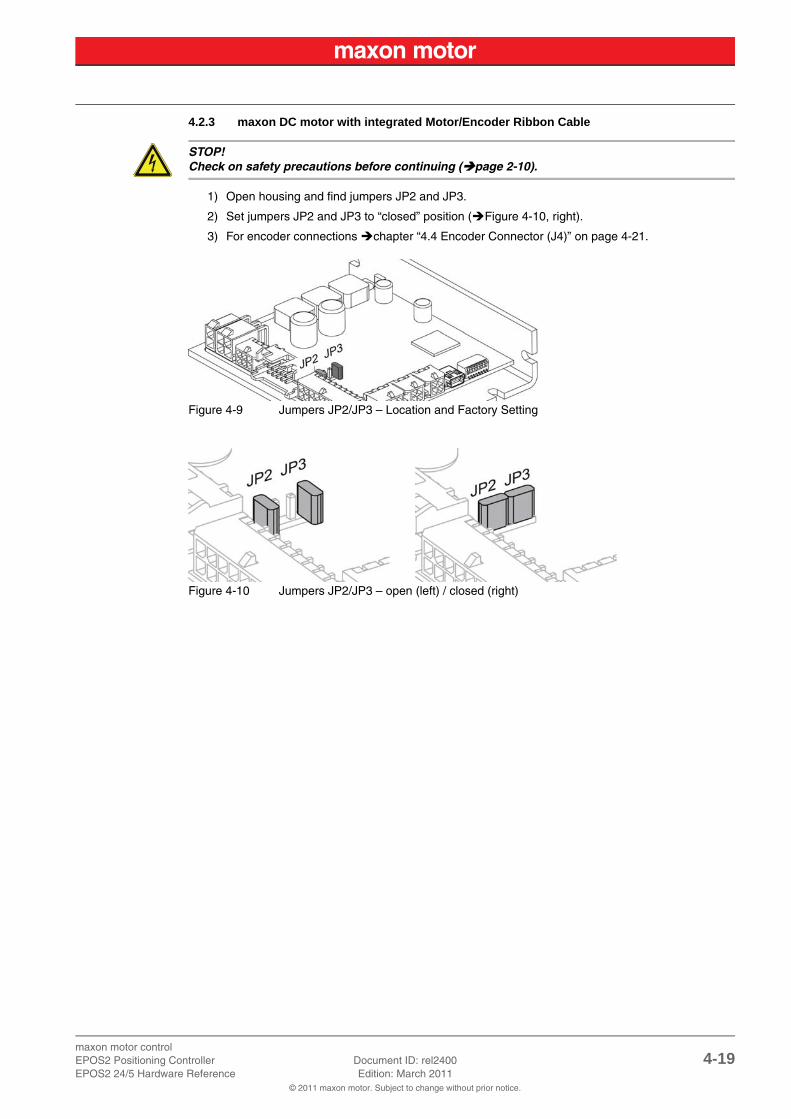
4.2.3 maxon DC motor with integrated Motor/Encoder Ribbon Cable
STOP!Check on safety precautions before continuing (page 2-10).
1) Open housing and find jumpers JP2 and JP3.
2) Set jumpers JP2 and JP3 to “closed” position (Figure 4-10, right).
3) For encoder connections chapter “4.4 Encoder Connector (J4)” on page 4-21.
Figure 4-9 Jumpers JP2/JP3 – Location and Factory Setting
Figure 4-10 Jumpers JP2/JP3 – open (left) / closed (right)
maxon motor control4-20 Document ID: rel2400 EPOS2 Positioning Controller
Edition: March 2011 EPOS2 24/5 Hardware Reference© 2011 maxon motor. Subject to change without prior notice.
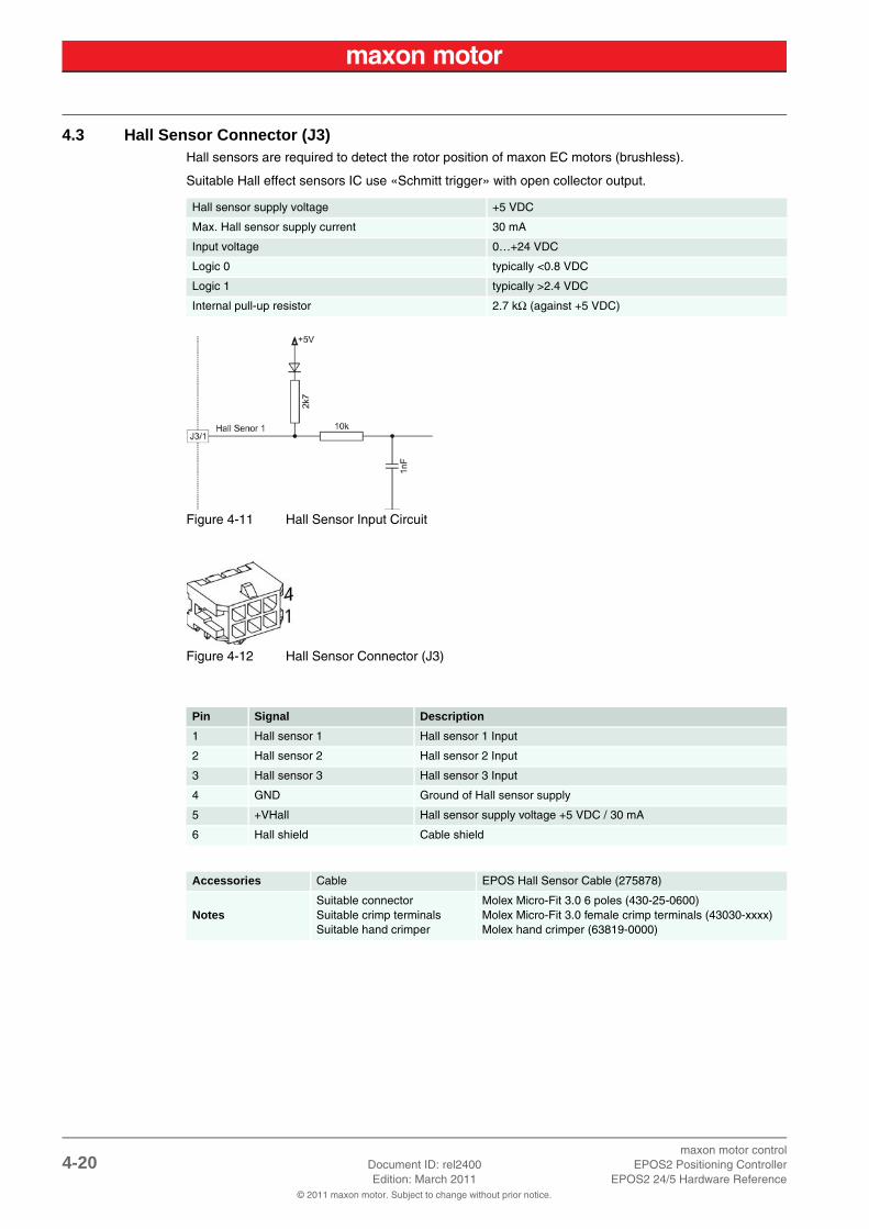
4.3 Hall Sensor Connector (J3)Hall sensors are required to detect the rotor position of maxon EC motors (brushless).
Suitable Hall effect sensors IC use «Schmitt trigger» with open collector output.
Figure 4-11 Hall Sensor Input Circuit
Figure 4-12 Hall Sensor Connector (J3)
Hall sensor supply voltage +5 VDC
Max. Hall sensor supply current 30 mA
Input voltage 0…+24 VDC
Logic 0 typically <0.8 VDC
Logic 1 typically >2.4 VDC
Internal pull-up resistor 2.7 kΩ (against +5 VDC)
Pin Signal Description
1 Hall sensor 1 Hall sensor 1 Input
2 Hall sensor 2 Hall sensor 2 Input
3 Hall sensor 3 Hall sensor 3 Input
4 GND Ground of Hall sensor supply
5 +VHall Hall sensor supply voltage +5 VDC / 30 mA
6 Hall shield Cable shield
Accessories Cable EPOS Hall Sensor Cable (275878)
NotesSuitable connectorSuitable crimp terminalsSuitable hand crimper
Molex Micro-Fit 3.0 6 poles (430-25-0600)Molex Micro-Fit 3.0 female crimp terminals (43030-xxxx)Molex hand crimper (63819-0000)

maxon motor controlEPOS2 Positioning Controller Document ID: rel2400 4-21EPOS2 24/5 Hardware Reference Edition: March 2011
© 2011 maxon motor. Subject to change without prior notice.
4.4 Encoder Connector (J4)
Best PracticeThe use of encoder with built-in line driver is mandatory.Even though 2-channel will do, we strongly recommend to use only 3-channel versions!
By default, the controller is set for a 500 count per turn encoder. For other encoders, you will need to adjust respective settings via software.
Figure 4-13 Encoder Input Channel
Encoder supply voltage +5 VDC
Max. encoder supply current 100 mA
Min. differential Input voltage ±200 mV
Line receiver (internal) EIA RS422 Standard
Max. encoder input frequency 5 MHz

maxon motor control4-22 Document ID: rel2400 EPOS2 Positioning Controller
Edition: March 2011 EPOS2 24/5 Hardware Reference© 2011 maxon motor. Subject to change without prior notice.
Figure 4-14 Encoder Connector (J4)
Remark:
*1) may require change of jumper (J2 / J3) settings (chapter “4.2.3 maxon DC motor with inte-grated Motor/Encoder Ribbon Cable” on page 4-19)
Best PracticeAmong other encoders, pin out perfectly suits…
• maxon digital MR-Encoder type S, M, ML, L all with Line Driver• maxon digital encoder HEDL 55_ with Line Driver RS422
Pin Signal Description
1EC motor: noneDC motor: Motor +
EC motor: not connectedDC motor: + Motor *1)
2 +5 VDC / 100 mA Encoder supply voltage
3 GND Ground
4EC motor: noneDC motor: Motor -
EC motor: not connectedDC motor: - Motor *1)
5 Channel A\ Channel A complement
6 Channel A Channel A
7 Channel B\ Channel B complement
8 Channel B Channel B
9 Channel I\ Index complement
10 Channel I Index
Accessories Cable EPOS Encoder Cable (275934)
Notes Suitable connector DIN 41651 Plug, pitch 2.54 mm, 10 poles, plug strain relief

maxon motor controlEPOS2 Positioning Controller Document ID: rel2400 4-23EPOS2 24/5 Hardware Reference Edition: March 2011
© 2011 maxon motor. Subject to change without prior notice.
4.5 Signal Connector (J5)Contains smart multi-purpose digital I/Os configurable as “Positive Limit Switch”, “Negative Limit Switch”, “Home Switch” and “Brake Output”.
Additionally offered are “General Purpose” digital inputs and outputs and analog inputs.
Figure 4-15 Signal Connector (J5)
Remarks:
*1) jumper JP4 is set (initial setting)
*2) if jumper JP4 is open, a independent logic supply voltage may be applied (chapter “4.1.2 Use of separate Logic Supply” on page 4-17)
Pin Signal Description
1 D_Gnd Digital signal ground
2 D_Gnd Digital signal ground
3 DigIN6 Digital Input 6 “Negative Limit Switch”
4 DigIN5 Digital Input 5 “Positive Limit Switch”
5 DigIN4 Digital Input 4 “Home Switch”
6 DigIN3 Digital Input 3 “General Purpose”
7 DigIN2 Digital Input 2 “General Purpose”
8 DigIN1 Digital Input 1 “General Purpose”
9+VOUT *1)
+VC *2)
Auxiliary supply voltage output (+11…24 VDC)Logic supply voltage input (+11…24 VDC)
10 DigOUT4 Digital Output 4 “Brake”
11 DigOUT3 Digital Output 3 “General Purpose”
12 DigOUT2 Digital Output 2 “General Purpose”
13 DigOUT1 Digital Output 1 “General Purpose”
14 A_Gnd Analog signal ground
15 AnIN2 Analog Input 2
16 AnIN1 Analog Input 1
Accessories Cable EPOS Signal Cable 1 (275932)
NotesSuitable connectorSuitable crimp terminalsSuitable hand crimper
Molex Micro-Fit 3.0 16 poles (430-25-1600)Molex Micro-Fit 3.0 female crimp terminals (43030-xxxx)Molex hand crimper (63819-0000)

maxon motor control4-24 Document ID: rel2400 EPOS2 Positioning Controller
Edition: March 2011 EPOS2 24/5 Hardware Reference© 2011 maxon motor. Subject to change without prior notice.
4.5.1 Digital Inputs 1, 2 and 3
By default, the digital inputs are defined as “General Purpose” and may be configured via software.
Figure 4-16 DigIN1 Circuit (analogously valid also for DigIN2/3)
DigIN1 “General Purpose”DigIN2 “General Purpose”DigIN3 “General Purpose”D_Gnd
Connector [J5] Pin [8]Connector [J5] Pin [7]Connector [J5] Pin [6]Connector [J5] Pin [1], [2]
Input voltage 0…24 VDC
Max. input voltage ±30 VDC
Logic 0 typically <1.5 V
Logic 1 typically >3.0 V
Input resistance typically 8 kΩ
Input current at logic 1 typically 3 mA @ 24 VDC
Switching delay <2 µs @ 5 VDC
maxon motor controlEPOS2 Positioning Controller Document ID: rel2400 4-25EPOS2 24/5 Hardware Reference Edition: March 2011
© 2011 maxon motor. Subject to change without prior notice.
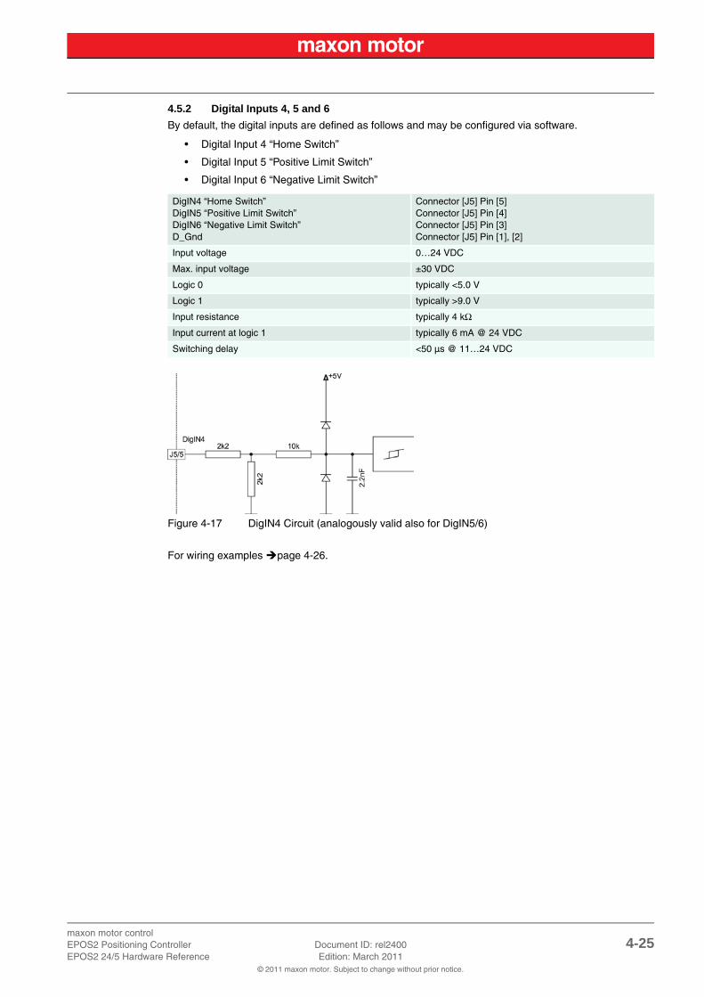
4.5.2 Digital Inputs 4, 5 and 6
By default, the digital inputs are defined as follows and may be configured via software.
• Digital Input 4 “Home Switch”
• Digital Input 5 “Positive Limit Switch”
• Digital Input 6 “Negative Limit Switch”
Figure 4-17 DigIN4 Circuit (analogously valid also for DigIN5/6)
For wiring examples page 4-26.
DigIN4 “Home Switch”DigIN5 “Positive Limit Switch”DigIN6 “Negative Limit Switch”D_Gnd
Connector [J5] Pin [5]Connector [J5] Pin [4]Connector [J5] Pin [3]Connector [J5] Pin [1], [2]
Input voltage 0…24 VDC
Max. input voltage ±30 VDC
Logic 0 typically <5.0 V
Logic 1 typically >9.0 V
Input resistance typically 4 kΩ
Input current at logic 1 typically 6 mA @ 24 VDC
Switching delay <50 µs @ 11…24 VDC
maxon motor control4-26 Document ID: rel2400 EPOS2 Positioning Controller
Edition: March 2011 EPOS2 24/5 Hardware Reference© 2011 maxon motor. Subject to change without prior notice.
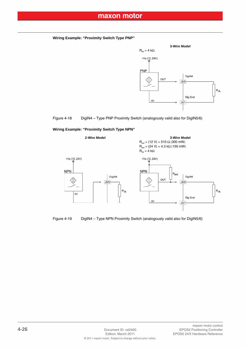
Wiring Example: “Proximity Switch Type PNP”
Figure 4-18 DigIN4 – Type PNP Proximity Switch (analogously valid also for DigIN5/6)
Wiring Example: “Proximity Switch Type NPN”
Figure 4-19 DigIN4 – Type NPN Proximity Switch (analogously valid also for DigIN5/6)
3-Wire ModelRIN = 4 kΩ
2-Wire Model 3-Wire ModelRext = (12 V) = 510 Ω (300 mW)Rext = (24 V) = 4.3 kΩ (150 mW)RIN = 4 kΩ
maxon motor controlEPOS2 Positioning Controller Document ID: rel2400 4-27EPOS2 24/5 Hardware Reference Edition: March 2011
© 2011 maxon motor. Subject to change without prior notice.
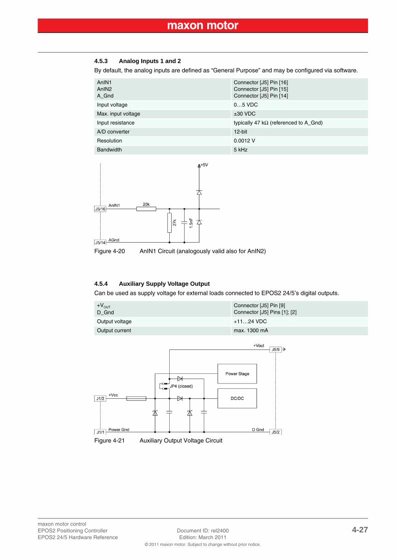
4.5.3 Analog Inputs 1 and 2
By default, the analog inputs are defined as “General Purpose” and may be configured via software.
Figure 4-20 AnIN1 Circuit (analogously valid also for AnIN2)
4.5.4 Auxiliary Supply Voltage Output
Can be used as supply voltage for external loads connected to EPOS2 24/5’s digital outputs.
Figure 4-21 Auxiliary Output Voltage Circuit
AnIN1AnIN2A_Gnd
Connector [J5] Pin [16]Connector [J5] Pin [15]Connector [J5] Pin [14]
Input voltage 0…5 VDC
Max. input voltage ±30 VDC
Input resistance typically 47 kΩ (referenced to A_Gnd)
A/D converter 12-bit
Resolution 0.0012 V
Bandwidth 5 kHz
+VOUT
D_GndConnector [J5] Pin [9]Connector [J5] Pins [1]; [2]
Output voltage +11…24 VDC
Output current max. 1300 mA

maxon motor control4-28 Document ID: rel2400 EPOS2 Positioning Controller
Edition: March 2011 EPOS2 24/5 Hardware Reference© 2011 maxon motor. Subject to change without prior notice.
4.5.5 Digital Outputs 1, 2 and 3
By default, the digital outputs are defined as “General Purpose” and may be configured via software.
Figure 4-22 DigOUT1 Circuit (analogously valid also for DigOUT2/3)
Wiring Examples:
Figure 4-23 DigOUT1 “Sinks” Circuit (analogously valid also for DigOUT2/3)
Figure 4-24 DigOUT1 “Source” Circuit (analogously valid also for DigOUT2/3)
DigOUT1DigOUT2DigOUT3D_Gnd
Connector [J5] Pin [13]Connector [J5] Pin [12]Connector [J5] Pin [11]Connector [J5] Pins [1]; [2]
CircuitOpen drain (internal pull-up resistor 2k2 and diode to +5 VDC
DigOUT “Sinks”
Max. input voltage +30 VDC
Max. load current 100 mA
Max. voltage drop 0.5 V @ 100 mA
DigOUT “Source”
Output voltage Uout ≈5V-0.75 V - (Iload × 2200 Ω)
Max. load current Iload ≤2 mA
maxon motor controlEPOS2 Positioning Controller Document ID: rel2400 4-29EPOS2 24/5 Hardware Reference Edition: March 2011
© 2011 maxon motor. Subject to change without prior notice.
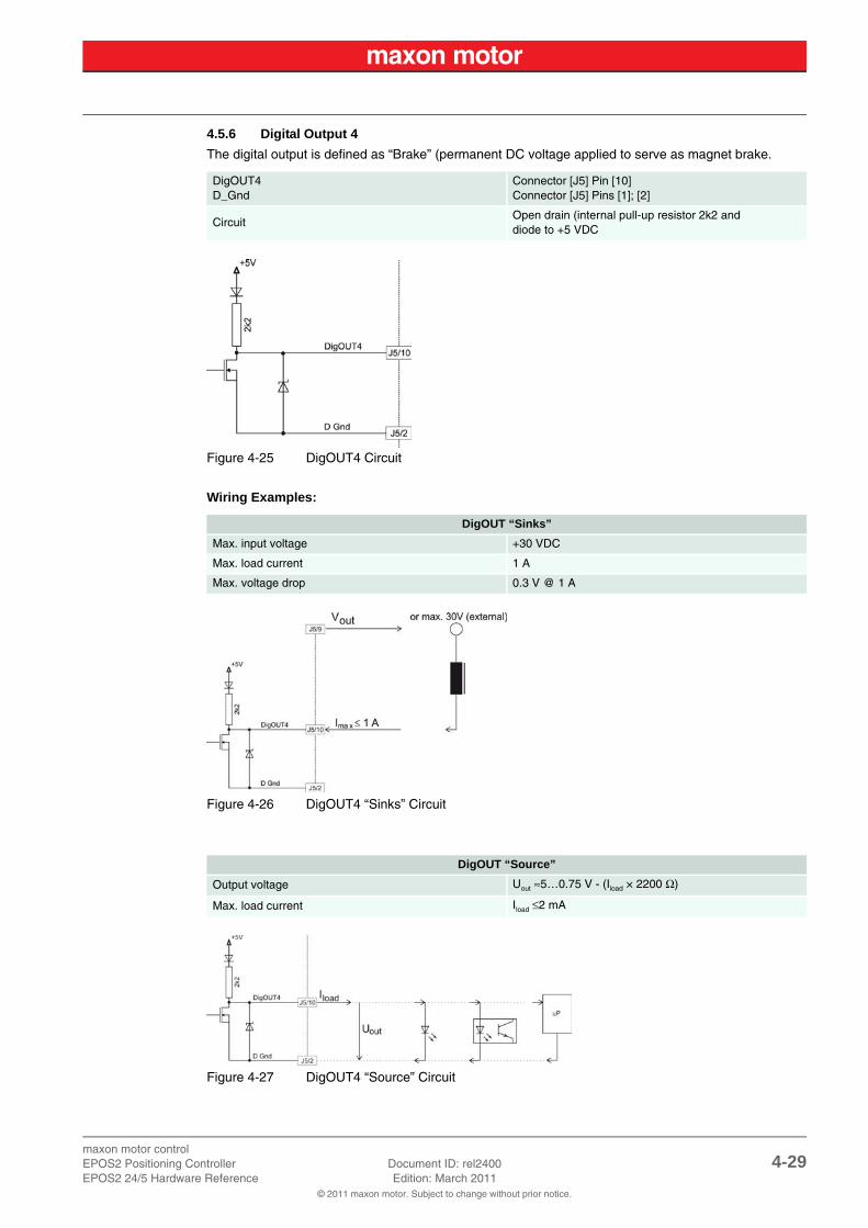
4.5.6 Digital Output 4
The digital output is defined as “Brake” (permanent DC voltage applied to serve as magnet brake.
Figure 4-25 DigOUT4 Circuit
Wiring Examples:
Figure 4-26 DigOUT4 “Sinks” Circuit
Figure 4-27 DigOUT4 “Source” Circuit
DigOUT4D_Gnd
Connector [J5] Pin [10]Connector [J5] Pins [1]; [2]
CircuitOpen drain (internal pull-up resistor 2k2 and diode to +5 VDC
DigOUT “Sinks”
Max. input voltage +30 VDC
Max. load current 1 A
Max. voltage drop 0.3 V @ 1 A
DigOUT “Source”
Output voltage Uout ≈5…0.75 V - (Iload × 2200 Ω)
Max. load current Iload ≤2 mA

maxon motor control4-30 Document ID: rel2400 EPOS2 Positioning Controller
Edition: March 2011 EPOS2 24/5 Hardware Reference© 2011 maxon motor. Subject to change without prior notice.
4.6 RS232 Connector (J6)
Connection of Positioning Controller to PC
Note• Consider your PC's serial port maximal baud rate.• The standard baud rate setting (factory setting) is 115'200 bauds.
Figure 4-28 RS232 Connector (J6)
Max. input voltage ±30 V
Output voltage typically ±9 V @ 3 kΩ to Ground
Max. bit rate 115 200 bit/s
Internal RS232 driver/receiver EIA RS232 Standard
EPOS2 24/5 PC Interface (RS232), DIN41652
Connector [J6] Pins [4] + [5] “GND” Pin 5 “GND”
Connector [J6] Pin [1] “EPOS RxD” Pin 3 “PC TxD”
Connector [J6] Pin [2] “EPOS TxD” Pin 2 “PC RxD”
Pin Signal Description
1 EPOS RxD EPOS RS232 receive
2 EPOS TxD EPOS RS232 transmit
3 not connected
4 GND RS232_Ground
5 GND RS232_Ground
6 Shield Cable shield
Accessories Cable EPOS RS232-COM Cable (275900)
NotesSuitable connectorSuitable crimp terminalsSuitable hand crimper
Molex Micro-Fit 3.0 6 poles (430-25-0600)Molex Micro-Fit 3.0 female crimp terminals (43030-xxxx)Molex hand crimper (63819-0000)

maxon motor controlEPOS2 Positioning Controller Document ID: rel2400 4-31EPOS2 24/5 Hardware Reference Edition: March 2011
© 2011 maxon motor. Subject to change without prior notice.
4.7 CAN Connector (J7, J8)
Connection of Positioning Controller to CAN Bus Line CiA DS-102
Note• Consider CAN Master’s maximal baud rate.• The standard baud rate setting (factory setting) is “Auto Bit Rate”.• Use termination resistor at both ends of the CAN bus (chapter “4.8.2 CAN Bus Termination” on
page 4-33).• For detailed CAN information separate document «EPOS2 Communication Guide».
Figure 4-29 CAN Connector (J7/J8)
Standard type CAN high-speed ISO 11898 compatible
Max. bit rate 1 Mbit/s
Max. number of CAN nodes 127
Protocol CANopen DS-301
Identifier setting DIP switch or software
EPOS2 24/5 CAN 9 pin D-Sub (DIN41652)
Connector [J7] or [J8] Pin [1] “CAN high” Pin 7 “CAN_H” high bus line
Connector [J7] or [J8] Pin [2] “CAN low” Pin 2 “CAN_L” low bus line”
Connector [J7] or [J8] Pin [3] “CAN GND” Pin 3 “CAN_GND” Ground
Connector [J7] or [J8] Pin [4] “CAN shield” Pin 5 “CAN_Shield” cable shield
Pin Signal Description
1 CAN high CAN high bus line
2 CAN low CAN low bus line
3 CAN GND CAN Ground
4 CAN shield Cable shield
Accessories CablesEPOS CAN-COM Cable (275908)EPOS CAN-CAN Cable (275926)EPOS CAN Termination Plug (275937)
NotesSuitable connectorSuitable crimp terminalsSuitable hand crimper
Molex Micro-Fit 3.0 4 poles (430-25-0400)Molex Micro-Fit 3.0 female crimp terminals (43030-xxxx)Molex hand crimper (63819-0000)

maxon motor control4-32 Document ID: rel2400 EPOS2 Positioning Controller
Edition: March 2011 EPOS2 24/5 Hardware Reference© 2011 maxon motor. Subject to change without prior notice.
4.8 CAN Configuration (JP1)
4.8.1 CAN ID (Node Address)
The CAN ID is set with DIP switches 1…7. Addresses (1…127) may be coded using binary code.
Note• By setting the DIP switch (1…7) address 0 (“OFF”), the CAN ID may be configured by software
(changing object “Node ID”, range 1…127).• The CAN ID results in the summed values of DIP switch addresses 1 (“ON”).• DIP switch 8 does not have any impact on the CAN ID.
Table 4-14 CAN ID – Binary Code Values
Examples:
Use following table as a (non-concluding) guide:
Table 4-15 CAN ID – DIP Switch Settings (Example)
Switch Binary Code Valence DIP Switch
1 20 1
Figure 4-30 JP1 (Numbering Scheme)
2 21 2
3 22 4
4 23 8
5 24 16
6 25 32
7 26 64
CAN ID/Switch 1 2 3 4 5 6 7
Valence 1 2 4 8 16 32 64
CAN ID DIP Setting Calculation
1 1 0 0 0 0 0 0 1
2 0 1 0 0 0 0 0 2
32 0 0 0 0 0 1 0 32
35 1 1 0 0 0 1 0 1 + 2 + 32
127 1 1 1 1 1 1 11 + 2 + 4 + 8 + 16 + 32 + 64

maxon motor controlEPOS2 Positioning Controller Document ID: rel2400 4-33EPOS2 24/5 Hardware Reference Edition: March 2011
© 2011 maxon motor. Subject to change without prior notice.
4.8.2 CAN Bus Termination
The CAN bus must be terminated at both ends by a termination resistor of 120 Ω, typically. Depending on utilization of the controller, individual CAN bus termination settings must be performed.
Using DIP switch 8, the controller-internal bus termination resistor can be activated/deactivated. By default, bus termination is “OFF”, nevertheless, the bus is not terminated.
Figure 4-31 DIP Switch (JP1 [8]) – CAN Bus Termination (left “OFF” right “ON”)
Example 1: Multiple Axis System with EPOS2 24/5 within CANopen Bus
Figure 4-32 EPOS2 24/5 without CAN Bus Termination
Example 2: Multiple Axis System with EPOS2 24/5 both Ends of CANopen Bus
Figure 4-33 EPOS2 24/5 with CAN Bus Termination
maxon motor control4-34 Document ID: rel2400 EPOS2 Positioning Controller
Edition: March 2011 EPOS2 24/5 Hardware Reference© 2011 maxon motor. Subject to change without prior notice.
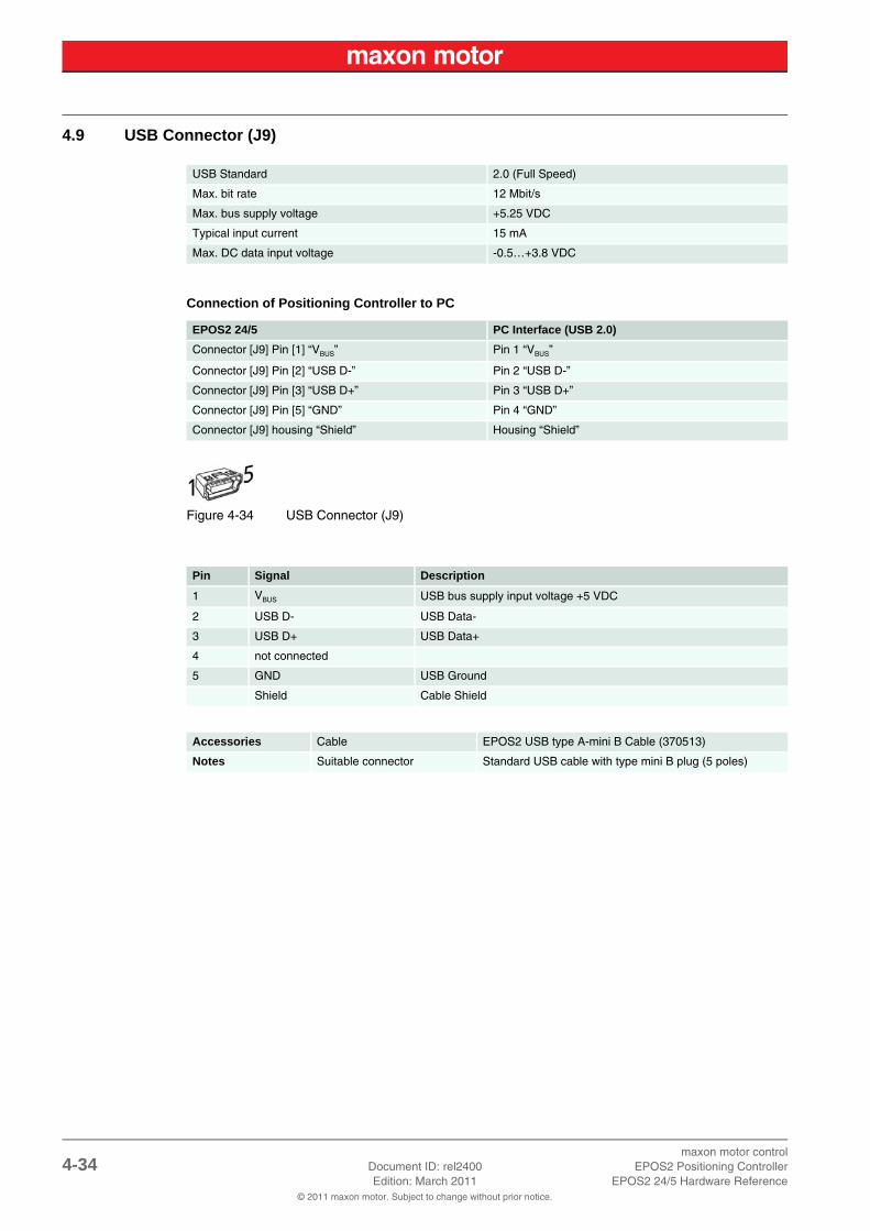
4.9 USB Connector (J9)
Connection of Positioning Controller to PC
Figure 4-34 USB Connector (J9)
USB Standard 2.0 (Full Speed)
Max. bit rate 12 Mbit/s
Max. bus supply voltage +5.25 VDC
Typical input current 15 mA
Max. DC data input voltage -0.5…+3.8 VDC
EPOS2 24/5 PC Interface (USB 2.0)
Connector [J9] Pin [1] “VBUS” Pin 1 “VBUS”
Connector [J9] Pin [2] “USB D-” Pin 2 “USB D-”
Connector [J9] Pin [3] “USB D+” Pin 3 “USB D+”
Connector [J9] Pin [5] “GND” Pin 4 “GND”
Connector [J9] housing “Shield” Housing “Shield”
Pin Signal Description
1 VBUS USB bus supply input voltage +5 VDC
2 USB D- USB Data-
3 USB D+ USB Data+
4 not connected
5 GND USB Ground
Shield Cable Shield
Accessories Cable EPOS2 USB type A-mini B Cable (370513)
Notes Suitable connector Standard USB cable with type mini B plug (5 poles)

maxon motor controlEPOS2 Positioning Controller Document ID: rel2400 4-35EPOS2 24/5 Hardware Reference Edition: March 2011
© 2011 maxon motor. Subject to change without prior notice.
4.10 Status LEDs The LEDs display the current status of the EPOS2 24/5 as well as possible errors:
• Green LED shows the operating status
• Red LED indicates errors
For detailed information separate document «EPOS2 Firmware Specification».
Table 4-16 LEDs – Interpretation of Condition
LEDStatus / Error
Red Green
OFF Slow
Power stage is disabled. Device is in status…• “Switch ON Disabled”• “Ready to Switch ON”• “Switched ON”
OFF ONPower stage is enabled. Device is in status…• “Operation Enable”• “Quick Stop Active”
ON OFFFAULT state. Device is in status…• “Fault”
ON ONPower stage is enabled. Device is in temporary status…• “Fault Reaction Active”
ON Flash No valid firmware or firmware download in progress.
Flash = Flashing (≈0.9 s OFF/≈0.1 s ON)Slow = Slow blinking (≈1 Hz)

maxon motor control4-36 Document ID: rel2400 EPOS2 Positioning Controller
Edition: March 2011 EPOS2 24/5 Hardware Reference© 2011 maxon motor. Subject to change without prior notice.
• • p a g e i n t e n t i o n a l l y l e f t b l a n k • •

maxon motor controlEPOS2 Positioning Controller Document ID: rel2400 Z-37EPOS2 24/5 Hardware Reference Edition: March 2011
© 2011 maxon motor. Subject to change without prior notice.
Figure 2-1 Documentation Structure . . . . . . . . . . . . . . . . . . . . . . . . . . . . . . . . . . . . . . . . . . . . . . . .9
Figure 3-2 Dimensional Drawing [mm]. . . . . . . . . . . . . . . . . . . . . . . . . . . . . . . . . . . . . . . . . . . . . .14
Figure 4-3 Interfaces – Designations and Location . . . . . . . . . . . . . . . . . . . . . . . . . . . . . . . . . . . .15
Figure 4-4 Wiring Diagram. . . . . . . . . . . . . . . . . . . . . . . . . . . . . . . . . . . . . . . . . . . . . . . . . . . . . . .15
Figure 4-5 Power Connector (J1). . . . . . . . . . . . . . . . . . . . . . . . . . . . . . . . . . . . . . . . . . . . . . . . . .16
Figure 4-6 Jumper JP4 – Location and Factory Setting. . . . . . . . . . . . . . . . . . . . . . . . . . . . . . . . .17
Figure 4-7 Jumper JP4 – closed (left) / open (right). . . . . . . . . . . . . . . . . . . . . . . . . . . . . . . . . . . .17
Figure 4-8 Motor Connector (J2) . . . . . . . . . . . . . . . . . . . . . . . . . . . . . . . . . . . . . . . . . . . . . . . . . .18
Figure 4-9 Jumpers JP2/JP3 – Location and Factory Setting . . . . . . . . . . . . . . . . . . . . . . . . . . . .19
Figure 4-10 Jumpers JP2/JP3 – open (left) / closed (right) . . . . . . . . . . . . . . . . . . . . . . . . . . . . . . .19
Figure 4-11 Hall Sensor Input Circuit . . . . . . . . . . . . . . . . . . . . . . . . . . . . . . . . . . . . . . . . . . . . . . . .20
Figure 4-12 Hall Sensor Connector (J3) . . . . . . . . . . . . . . . . . . . . . . . . . . . . . . . . . . . . . . . . . . . . .20
Figure 4-13 Encoder Input Channel . . . . . . . . . . . . . . . . . . . . . . . . . . . . . . . . . . . . . . . . . . . . . . . . .21
Figure 4-14 Encoder Connector (J4) . . . . . . . . . . . . . . . . . . . . . . . . . . . . . . . . . . . . . . . . . . . . . . . .22
Figure 4-15 Signal Connector (J5) . . . . . . . . . . . . . . . . . . . . . . . . . . . . . . . . . . . . . . . . . . . . . . . . . .23
Figure 4-16 DigIN1 Circuit (analogously valid also for DigIN2/3). . . . . . . . . . . . . . . . . . . . . . . . . . .24
Figure 4-17 DigIN4 Circuit (analogously valid also for DigIN5/6). . . . . . . . . . . . . . . . . . . . . . . . . . .25
Figure 4-18 DigIN4 – Type PNP Proximity Switch (analogously valid also for DigIN5/6) . . . . . . . .26
Figure 4-19 DigIN4 – Type NPN Proximity Switch (analogously valid also for DigIN5/6) . . . . . . . .26
Figure 4-20 AnIN1 Circuit (analogously valid also for AnIN2) . . . . . . . . . . . . . . . . . . . . . . . . . . . . .27
Figure 4-21 Auxiliary Output Voltage Circuit . . . . . . . . . . . . . . . . . . . . . . . . . . . . . . . . . . . . . . . . . .27
Figure 4-22 DigOUT1 Circuit (analogously valid also for DigOUT2/3). . . . . . . . . . . . . . . . . . . . . . .28
Figure 4-23 DigOUT1 “Sinks” Circuit (analogously valid also for DigOUT2/3). . . . . . . . . . . . . . . . .28
Figure 4-24 DigOUT1 “Source” Circuit (analogously valid also for DigOUT2/3) . . . . . . . . . . . . . . .28
Figure 4-25 DigOUT4 Circuit . . . . . . . . . . . . . . . . . . . . . . . . . . . . . . . . . . . . . . . . . . . . . . . . . . . . . .29
Figure 4-26 DigOUT4 “Sinks” Circuit . . . . . . . . . . . . . . . . . . . . . . . . . . . . . . . . . . . . . . . . . . . . . . . .29
Figure 4-27 DigOUT4 “Source” Circuit. . . . . . . . . . . . . . . . . . . . . . . . . . . . . . . . . . . . . . . . . . . . . . .29
Figure 4-28 RS232 Connector (J6) . . . . . . . . . . . . . . . . . . . . . . . . . . . . . . . . . . . . . . . . . . . . . . . . .30
Figure 4-29 CAN Connector (J7/J8) . . . . . . . . . . . . . . . . . . . . . . . . . . . . . . . . . . . . . . . . . . . . . . . .31
Figure 4-30 JP1 (Numbering Scheme) . . . . . . . . . . . . . . . . . . . . . . . . . . . . . . . . . . . . . . . . . . . . . .32
Figure 4-31 DIP Switch (JP1 [8]) – CAN Bus Termination (left “OFF” right “ON”) . . . . . . . . . . . . . .33
Figure 4-32 EPOS2 24/5 without CAN Bus Termination . . . . . . . . . . . . . . . . . . . . . . . . . . . . . . . . .33
Figure 4-33 EPOS2 24/5 with CAN Bus Termination. . . . . . . . . . . . . . . . . . . . . . . . . . . . . . . . . . . .33
Figure 4-34 USB Connector (J9) . . . . . . . . . . . . . . . . . . . . . . . . . . . . . . . . . . . . . . . . . . . . . . . . . . .34
LIST OF FIGURES

maxon motor controlZ-38 Document ID: rel2400 EPOS2 Positioning Controller
Edition: March 2011 EPOS2 24/5 Hardware Reference© 2011 maxon motor. Subject to change without prior notice.
Table 1-1 Notations used in this Document . . . . . . . . . . . . . . . . . . . . . . . . . . . . . . . . . . . . . . . . . . 5
Table 1-2 Brand Names and Trademark Owners. . . . . . . . . . . . . . . . . . . . . . . . . . . . . . . . . . . . . . 7
Table 3-3 Electrical Data – Rating . . . . . . . . . . . . . . . . . . . . . . . . . . . . . . . . . . . . . . . . . . . . . . . . 11
Table 3-4 Electrical Data – Inputs . . . . . . . . . . . . . . . . . . . . . . . . . . . . . . . . . . . . . . . . . . . . . . . . 11
Table 3-5 Electrical Data – Outputs . . . . . . . . . . . . . . . . . . . . . . . . . . . . . . . . . . . . . . . . . . . . . . . 11
Table 3-6 Electrical Data – Voltage Outputs . . . . . . . . . . . . . . . . . . . . . . . . . . . . . . . . . . . . . . . . 12
Table 3-7 Electrical Data – Motor Connections . . . . . . . . . . . . . . . . . . . . . . . . . . . . . . . . . . . . . . 12
Table 3-8 Electrical Data – Interfaces . . . . . . . . . . . . . . . . . . . . . . . . . . . . . . . . . . . . . . . . . . . . . 12
Table 3-9 Electrical Data – LEDs . . . . . . . . . . . . . . . . . . . . . . . . . . . . . . . . . . . . . . . . . . . . . . . . . 12
Table 3-10 Electrical Data – Connections . . . . . . . . . . . . . . . . . . . . . . . . . . . . . . . . . . . . . . . . . . . 13
Table 3-11 Mechanical Data. . . . . . . . . . . . . . . . . . . . . . . . . . . . . . . . . . . . . . . . . . . . . . . . . . . . . . 14
Table 3-12 Environmental Conditions . . . . . . . . . . . . . . . . . . . . . . . . . . . . . . . . . . . . . . . . . . . . . . 14
Table 3-13 Order Details . . . . . . . . . . . . . . . . . . . . . . . . . . . . . . . . . . . . . . . . . . . . . . . . . . . . . . . . 14
Table 4-14 CAN ID – Binary Code Values . . . . . . . . . . . . . . . . . . . . . . . . . . . . . . . . . . . . . . . . . . . 32
Table 4-15 CAN ID – DIP Switch Settings (Example) . . . . . . . . . . . . . . . . . . . . . . . . . . . . . . . . . . 32
Table 4-16 LEDs – Interpretation of Condition . . . . . . . . . . . . . . . . . . . . . . . . . . . . . . . . . . . . . . . . 35
LIST OF TABLES

maxon motor controlEPOS2 Positioning Controller Document ID: rel2400 Z-39EPOS2 24/5 Hardware Reference Edition: March 2011
© 2011 maxon motor. Subject to change without prior notice.
Aadditionally applicable regulations 10alerts 5analog inputs 27
Bbackup power 17bus termination 33
Ccable
275829 16275851 18275878 20275900 30275908 31275926 31275932 23275934 22275937 31370513 34
calculation of required supply voltage 16CAN
bus termination 33interface 31
CAN ID settings 32connector
J1 16J2 18J3 20J4 21J5 23J6 30J7 31J8 31J9 34
country-specific regulations 10
Ddigital inputs 24, 25digital outputs 28, 29DIP switch
JP1 32JP1, bus termination 33JP1, numbering scheme 32
Eelectrical data 11encoders, suitable types 22environmental conditions, permitted 14error display 35ESD 10example
setting CAN IDs 32terminating CANopen bus 33wiring proximity switches 26
Hhow to
calculate required supply voltage 16configure CAN ID 32interpret icons (and signs) used in the document 5
Iinformatory signs 6intended purpose 9interface
CAN 31RS232 30USB 34
interfaces, location and designation 15
Jjumper
JP2 19JP3 19JP4 17
LLEDs 35
Mmandatory action signs 6mechanical data 14
NNode Address, configuration 32
Ooperating status, display 35
INDEX

maxon motor controlZ-40 Document ID: rel2400 EPOS2 Positioning Controller
Edition: March 2011 EPOS2 24/5 Hardware Reference© 2011 maxon motor. Subject to change without prior notice.
Pperformance data 11power backup 17precautions 10prohibitive signs 6purpose
of the device 9of this document 5
Rregulations, additionally applicable 10RS232
interface 30
Ssafety alerts 5safety first! 10signs
informative 6mandatory 6prohibitive 6
signs used 5status display 35status LEDs 35supply voltage, required 16symbols used 5
Ttechnical data 11
UUSB
interface 34
maxon motor controlEPOS2 Positioning Controller Document ID: rel2400 Z-41EPOS2 24/5 Hardware Reference Edition: March 2011
© 2011 maxon motor. Subject to change without prior notice.
• • p a g e i n t e n t i o n a l l y l e f t b l a n k • •

maxon motor controlZ-42 Document ID: rel2400 EPOS2 Positioning Controller
Edition: March 2011 EPOS2 24/5 Hardware Reference© 2011 maxon motor. Subject to change without prior notice.
© 2011 maxon motor. All rights reserved.
The present document – including all parts thereof – is protected by copyright. Any use (including reproduction, translation, microfilming and other means of electronic data processing) beyond the narrow restrictions of the copyright law without the prior approval of maxon motor ag, is not permitted and subject to persecution under the applicable law.
maxon motor agBrünigstrasse 220P.O.Box 263CH-6072 SachselnSwitzerland
Phone +41 (41) 666 15 00Fax +41 (41) 666 16 50
www.maxonmotor.com