Embed Size (px)
Citation preview

Equation Chapter 1 Section 1
CHAPTER I: INTRODUCTION
I.1 Context of the research
The use of concrete filled steel hollow section (CFSHS) columns for the construction of high-rise buildings, bridges, etc. has become increasingly popular in recent years. Some cross-sections representative of CFSHS columns are indicated in Figure I-1.
Figure I-1. Types of CFSHS column
The advantages of using CFSHS columns are (Bergmann (2004)): - The concrete filling gives to the steel hollow sections a higher rigidity and load
bearing capacity, so that the aesthetic slender columns can bear higher loads without increasing the external dimensions;
- This type of columns shows a high ductility and energy absorption capacity; - Hollow section acts as formwork as well as reinforcement for the concrete; - The time required for the hardening of concrete does not prevent the progress of the
construction. The time for assembly and erection is short without any delay; - The concrete core increases the fire resistance time compared to a hollow steel
section; - There is seldom any problem with respect to the joints due to the highly developed
assembly technique in structural engineering today. This permits prefabrication in workshop and a quick assembly on site.
Due to their advantages, CFSHS columns have a large potential to be used in high-rise building structures.
In recent years, the possibility of using self-compacting concrete (SCC) has been received very favourably by structural engineers. SCC may be considered as a revolution in the field of concrete technology. The self-compactability of concrete refers to the capability of the material to flow under its own weight and fill in the formwork in cast processing. Due to its rheological properties, many advantages can be mentioned and new structural applications can be realized. Among them CFSHS columns with small cross-section dimensions and dense reinforcement can be envisaged. However, with this type of profile, the loads that can be supported and the fire resistances that can be expected are very small.
1
Another application concerns tubes (hollow sections) surrounding another profile (tube or H section) filled partially or totally with concrete. The potentialities are here numerous and varied and involve profiles with larger dimensions. The use of self-compacting concrete will be appropriate if the space between two profiles is such that casting is almost impossible with normal vibrated concrete.
The behaviour of CFSHS columns under normal temperatures has been studied by a large number of researchers. Advanced models, which enable real boundary conditions to be considered and take into account second-order effects including residual stresses, geometrical imperfections, local instability, crack of concrete, creep and shrinkage of concrete, confinement effects and yielding of structural steel and of reinforcement, have been used to understand clearly the behaviour of CFSHS columns (Hajjar J.F. et al. (1996- 1998), Schneider S.P. (1998), Uy B. (1996-2001), Bradford A. (2002), , Han L.H (2001-2003). Bergmann R. et al. (2006), Ellobody E. et al. (2006)…). However, the handling of such methods is quite time-consuming and requires expert knowledge. For practical design, “simple calculation models” have been developed, which make it possible to determine the load capacity of composite columns even without the help of a computer. Different specific simple calculation models for the design of CFSHS columns can be found in codes or standards such as ACI 318M-05, ANSI/AISC 360-05, AIJ, Eurocodes. These methods lead to a comprehensive design but are limited in application range, for example: the percentage of reinforcing steel is less than 6%, concrete filled steel hollow sections containing another steel tube or profile are excluded. A simple calculation model for the design of CFSHS columns with small cross-section dimensions and dense reinforcement or embedded steel profile (where self-compacting concrete is needed) is still not available.
The study of the behaviour of CFSHS under fire condition is more involved than at normal temperature. This behaviour can be understood well by using advanced models (Lie et al. (1993c), Han L.H. (2001), Zha X.X (2003), Renaud C. et al. (2003, 2004), Schaumann P. et al. (2006), Ding J. and Wang Y.C (2005, 2008)), but simple calculation models for practical design are still very restricted. Research on the fire resistance of steel hollow section (SHS) columns filled with plain concrete and bar-reinforced concrete was previously completed by Lie T.T. and Kodur V.K.R. (1996) with the restricted limits: percentage of main reinforcing bars from 1.5 % to 5%, effective length of column from 2 m to 4.5 m. Besides, Eurocode EN 1994-1-2 (2004) provides a simplified calculation model in Annex H applicable to axially loaded circular or rectangular SHS columns filled with concrete. But the field of application of this method is restricted too: percentage on reinforcing steel less than 5%, buckling length less than 4.5 m.
Because experimental research on CFSHS column under fire conditions is very expensive, very few tests have been performed (Guyaux P. and Janss J. (1979), Kordina K. and Klingsch W. (1983), Lie T.T et al. (1988-1994), British Steel Report (1992), Han L.H (2003)). In these studies, all of the tested columns are steel hollow sections filled with normal vibrated concrete.
2
From the literature review it can be seen that the behaviour of CFSHS columns with small cross-section dimensions and dense reinforcement or embedded steel profile (where self-compacting concrete is needed) has not been studied yet.
This research tends to extend the field of applicability for designing CFSHS column under ordinary and fire conditions. The cross- sections are densely reinforced (percentage of reinforcing steel from 3.5% to 10%) or containing other steel profile where SCC need to be used.
The developments presented in this work are part of a large research project devoted to SHS columns filled with self-compacting concrete financed by the Belgian FNRS-FRFC (Fonds National de la Recherche Scientifique – National Funds for Scientific Research)
I.2 Objectives of the thesis The main objectives and contribution to be derived from this thesis are outlined as
follows:
- Verify appropriate numerical models using SAFIR computer code for analysis of CFSHS columns under ordinary and fire conditions.
- Undertake extensive investigation on CFSHS columns with small sections and dense reinforcement or embedded steel profile where self-compacting concrete is used. This type of columns is studied under both ordinary and fire conditions.
- Perform experimental investigation on the behaviour of steel hollow section columns filled with self-compacting concrete under standard fire conditions.
- Provide consulting engineers with a simplified method for calculating the fire resistance of CFSHS columns of small sections and dense reinforcement or embedded steel profile which have not been considered anywhere. Practical recommendations will also be given for columns of larger cross-sectional dimensions.
I.3 Content of the thesis
Apart from this introduction, the thesis comprises seven other chapters:
- Chapter II presents the state of the art regarding CFSHS columns under both ordinary and fire conditions. The behaviour of CFSHS columns and the factors affecting it are specified. Self-compacting concrete and its properties are also introduced in this chapter.
- Chapter III is devoted to advanced FEM calculations using SAFIR code, a non-linear finite element software developed at the University of Liège for the simulation of the structural behaviour under ordinary and fire conditions, in thermal and structural analysis of CFSHS columns. Tests results from literature were used to validate the computer code. Some calibrations have been performed.
- Using the model described in chapter III, the ultimate load of CFSHS columns at normal temperatures was calculated in chapter IV with varying parameters such as
3
cross-section dimensions, reinforcement ratios, concrete strengths and concrete covers. The type of cross-section concerned is small sections with dense reinforcement or embedded steel profile where SCC is needed. This type of cross-section is not included in existing design methods of Eurocodes. Simulation results are used to check if the current design method of EN 1994-1-1 is still valid for this type of cross-section and to see which European buckling curve is relevant for CFSHS columns with dense steel bar reinforcement or embedded steel profile.
- Chapter V describes the experimental research on steel hollow section columns filled with self-compacting concrete under standard fire tests. Ten columns with five different cross-sections have been tested. The cross-section dimensions vary from 200 mm to 273 mm. Simulations by SAFIR code were used to verify the numerical models for the analysis of CFSHS under fire conditions with the use of SCC. The aim of these calculations is to see whether the thermal and mechanical properties of self-compacting concrete are close to those of normal concrete.
- In order to give to consulting engineers more practical tools, a formula for calculating the fire resistance of SHS columns filled with concrete has been established and is presented in chapter VI. The field of applicability has been extended: effective length of column from 2 m to 7 m, percentage of reinforcing steel from 3.5 % to 10 %. Sections containing other steel profile are considered also. A formula for short columns with square section has been established based on SAFIR simulations taking into account the main parameters (quality of materials, dimensions, steel bars, and concrete cover). Further developments aim at showing whether the simplified equation can be used for other types of cross-sections, how the formula can be extended to slender columns, and how to treat columns with eccentric load.
- Previous chapters concentrated on CFSHS columns with small cross-section dimensions only (less than 300 mm). But the fire resistance of such small sectional columns is quite low. In order to get additional practical information, chapter VII contains numerical calculations of the fire resistance of larger profiles (dimensions up to 400 mm). The main objective of these numerical calculations is to provide practical recommendations and data for immediate use by practical engineers.
- Chapter VIII gives the conclusions and suggestions for further research.
4
Equation Chapter 2 Section 1
CHAPTER II: STATE OF THE ART
II.1 Hollow steel columns filled with concrete at normal temperatures
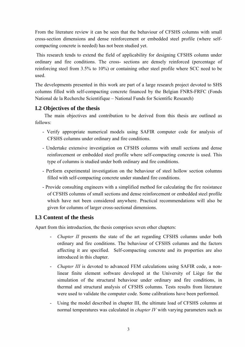
II.1.1 Introduction The use of concrete filled steel hollow section (CFSHS) columns for the construction of various types of buildings and more particularly for high-rise buildings has become increasingly popular in recent years. Some cross-sections representative of CFSHS columns are indicated in Figure I-1
Figure II-2. Types of CFSHS column
A number of factors complicate the analysis and the design of CFSHS. A CFSHS member contains two materials with different stress-strain curves and different behaviour. The interaction of the two materials gives rise to a difficult problem in the determination of combined properties such as moment of inertia and modulus of elasticity. The failure mechanism depends largely on the shape, length, diameter, steel tube thickness, and concrete and steel strengths. Parameters such as bond, concrete confinement, residual stress, creep, shrinkage, and type of loading also have an effect on CFSHS member behaviour.
This section presents the state of the art regarding CFSHS columns at normal temperature.
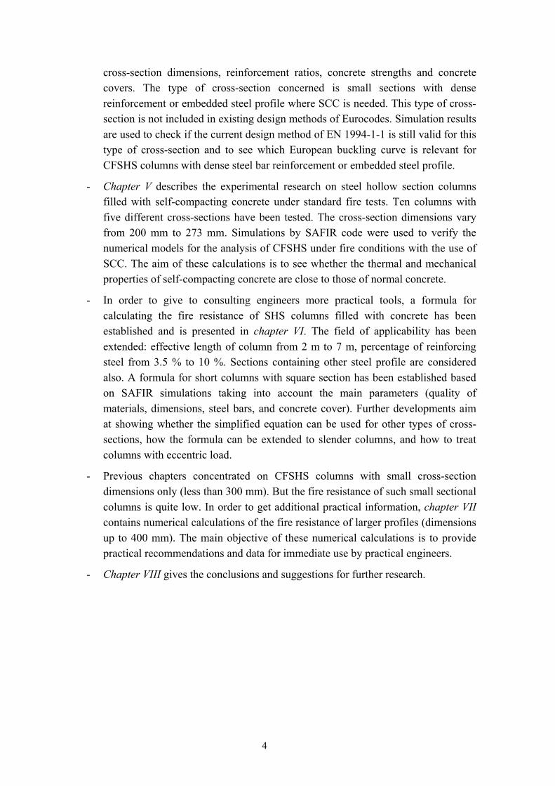
Depending on the type of cross-section CFSHS sections can be divided into two groups: conventional steel hollow section filled with concrete with or without reinforcement (Figure II-3), and concrete filled steel hollow sections containing another tube or profile (Figure II-4)
Figure II-3. Conventional CFSHS
5
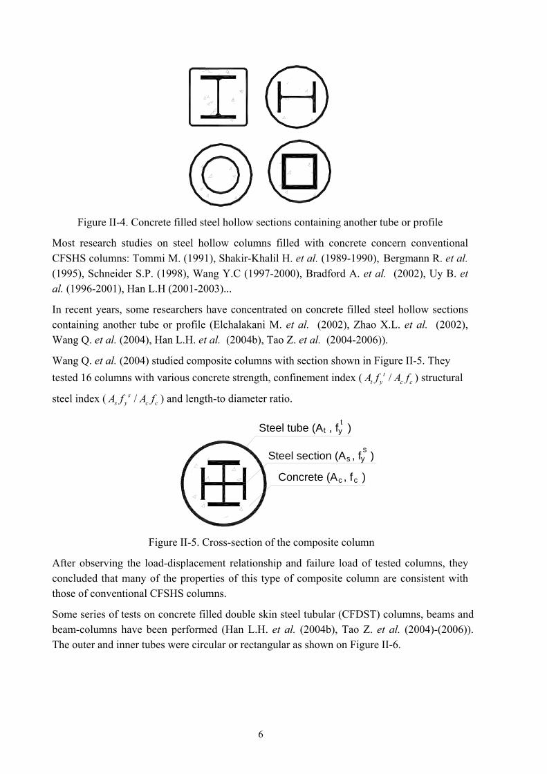
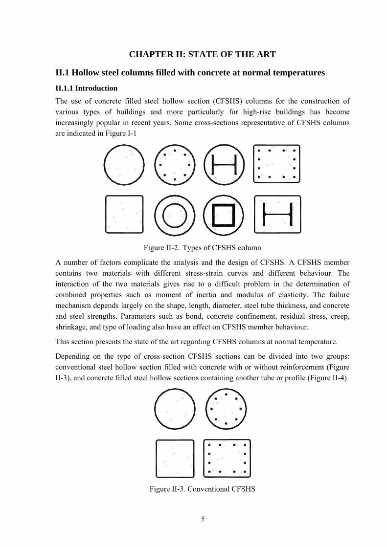
Figure II-4. Concrete filled steel hollow sections containing another tube or profile
Most research studies on steel hollow columns filled with concrete concern conventional CFSHS columns: Tommi M. (1991), Shakir-Khalil H. et al. (1989-1990), Bergmann R. et al. (1995), Schneider S.P. (1998), Wang Y.C (1997-2000), Bradford A. et al. (2002), Uy B. et al. (1996-2001), Han L.H (2001-2003)...
In recent years, some researchers have concentrated on concrete filled steel hollow sections containing another tube or profile (Elchalakani M. et al. (2002), Zhao X.L. et al. (2002), Wang Q. et al. (2004), Han L.H. et al. (2004b), Tao Z. et al. (2004-2006)).
Wang Q. et al. (2004) studied composite columns with section shown in Figure II-5. They tested 16 columns with various concrete strength, confinement index ( /t
t y c cA f A f ) structural
steel index ( /ss y c cA f A f ) and length-to diameter ratio.
Steel tube (A , f )
Steel section (A , f )
Concrete (A , f )
t yt
s ys
c c
Figure II-5. Cross-section of the composite column
After observing the load-displacement relationship and failure load of tested columns, they concluded that many of the properties of this type of composite column are consistent with those of conventional CFSHS columns.
Some series of tests on concrete filled double skin steel tubular (CFDST) columns, beams and beam-columns have been performed (Han L.H. et al. (2004b), Tao Z. et al. (2004)-(2006)). The outer and inner tubes were circular or rectangular as shown on Figure II-6.
6
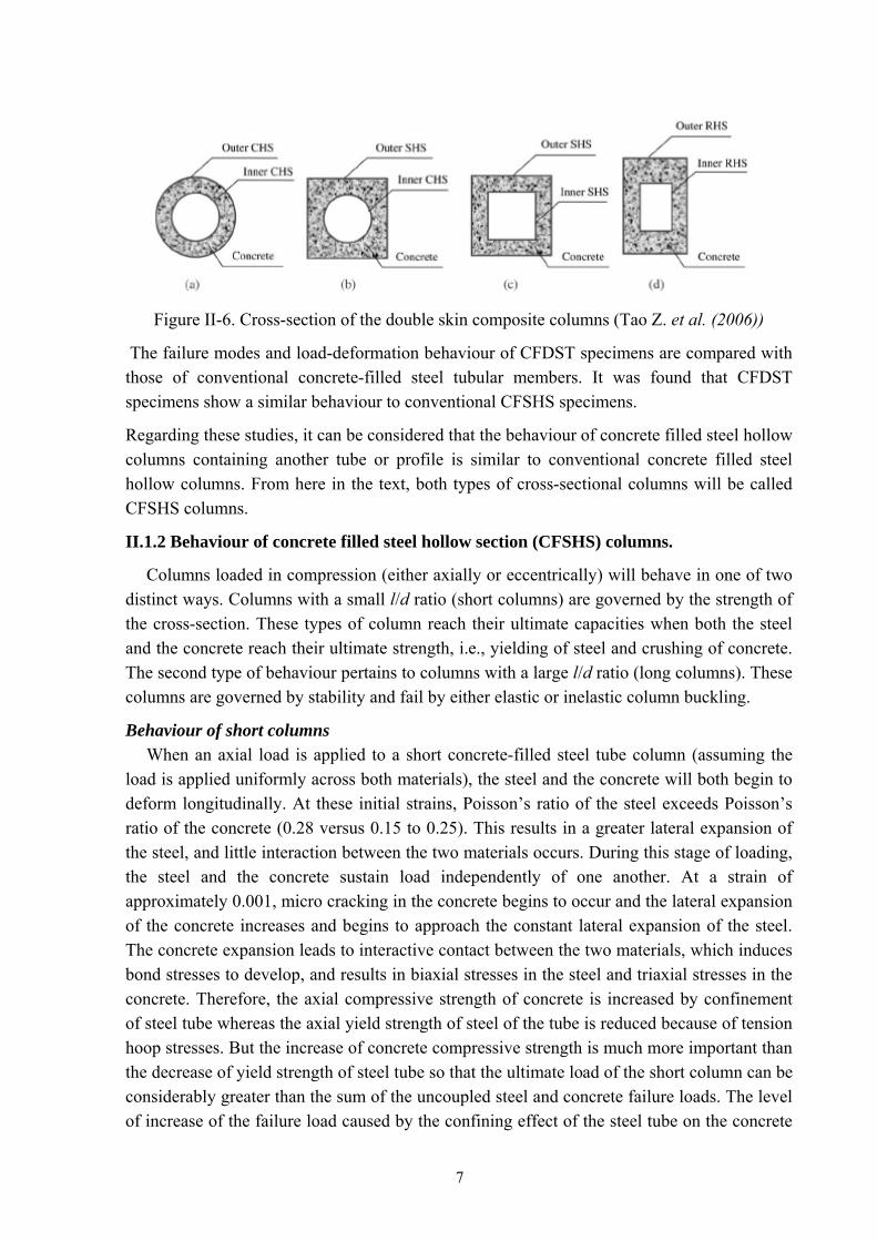
Figure II-6. Cross-section of the double skin composite columns (Tao Z. et al. (2006))
The failure modes and load-deformation behaviour of CFDST specimens are compared with those of conventional concrete-filled steel tubular members. It was found that CFDST specimens show a similar behaviour to conventional CFSHS specimens.
Regarding these studies, it can be considered that the behaviour of concrete filled steel hollow columns containing another tube or profile is similar to conventional concrete filled steel hollow columns. From here in the text, both types of cross-sectional columns will be called CFSHS columns.
II.1.2 Behaviour of concrete filled steel hollow section (CFSHS) columns.
Columns loaded in compression (either axially or eccentrically) will behave in one of two distinct ways. Columns with a small l/d ratio (short columns) are governed by the strength of the cross-section. These types of column reach their ultimate capacities when both the steel and the concrete reach their ultimate strength, i.e., yielding of steel and crushing of concrete. The second type of behaviour pertains to columns with a large l/d ratio (long columns). These columns are governed by stability and fail by either elastic or inelastic column buckling.
Behaviour of short columns When an axial load is applied to a short concrete-filled steel tube column (assuming the
load is applied uniformly across both materials), the steel and the concrete will both begin to deform longitudinally. At these initial strains, Poisson’s ratio of the steel exceeds Poisson’s ratio of the concrete (0.28 versus 0.15 to 0.25). This results in a greater lateral expansion of the steel, and little interaction between the two materials occurs. During this stage of loading, the steel and the concrete sustain load independently of one another. At a strain of approximately 0.001, micro cracking in the concrete begins to occur and the lateral expansion of the concrete increases and begins to approach the constant lateral expansion of the steel. The concrete expansion leads to interactive contact between the two materials, which induces bond stresses to develop, and results in biaxial stresses in the steel and triaxial stresses in the concrete. Therefore, the axial compressive strength of concrete is increased by confinement of steel tube whereas the axial yield strength of steel of the tube is reduced because of tension hoop stresses. But the increase of concrete compressive strength is much more important than the decrease of yield strength of steel tube so that the ultimate load of the short column can be considerably greater than the sum of the uncoupled steel and concrete failure loads. The level of increase of the failure load caused by the confining effect of the steel tube on the concrete
7
core depends on several factors, namely the thickness of the steel tube, slenderness ratio, eccentricity of the load and cross-sectional shape. Short columns can be further subdivided into two categories based on the ratio of the tube diameter (or depth) to thickness. Thin-walled specimens fail either by elastic or inelastic local buckling of the steel tube, or by shear failure in the concrete followed by local buckling of the steel tube, which is in a state of yielding. In this case, the confinement effects are insignificant. The local buckling of the steel is, however, delayed by the influence of the concrete core. The concrete core forces the steel to buckle in an outward mode. The failure of thick-walled short columns begins with the yielding of the steel. As the yielding of the cross-section of the tube proceeds, the concrete begins to fail by crushing. With the confinement, the concrete can continue to sustain additional load until the steel tube fails (usually by extensive local buckling or full plastification of the cross-section) corresponding to the ultimate strength of the section.
Behaviour of long columns While short columns usually attain the cross-sectional strength, long columns often fail by
flexural buckling. Second order effects become more critical. Overall column buckling will precede strains of sufficient magnitude to allow large volumetric expansion of the concrete to occur. Hence, for overall buckling failures, there is little confinement of the concrete and thus little additional strength gain. Both elastic and inelastic flexural buckling can occur in CFHSH columns. Columns that fail by inelastic buckling are referred to here as intermediate columns and those that fail by elastic buckling are referred to as slender columns. Intermediate columns will undergo some steel yielding and/or concrete crushing before buckling occurs. The failure mode of slender columns is characterized by overall elastic buckling of the member. This type of columns has a sufficiently large l/d ratio to cause buckling before any significant yielding occurs in the column.
II.1.3 Factors affecting the load resistance of CFSHS columns
Type of application on the load in the section A concrete-filled steel tube can be loaded in three theoretical basic ways: loading the steel only, loading the concrete only, or loading the entire section. Ideally, loading the concrete alone would be the most efficient method in the absence of bond between concrete and steel wall. The steel would be used only to confine the concrete and would contain no longitudinal stresses. Research by O’Shea M.D. and Bridge R.Q (2000) confirmed this. However, the lateral expansion of concrete creates pressure on the steel. Furthermore some bond will always exist between the two materials, inducing the axial stresses in the steel. It creates a biaxial state of stress in the steel tube. Research by Johansson M. and Gylltoft K. (2001) showed that when the load was applied only to the concrete core, the load resistance was approximately the same as when the load was applied to the entire section. On the contrary, the ultimate load is drastically reduced when the load is applied to the steel section only. The influence of bond strength between the concrete core and the steel tube on the behaviour of the columns was also investigated. The following physical explanations can be given. When the load is applied only to the concrete core, the axial force is gradually transferred from the
8
concrete to the steel, and the distribution as well as the structural behaviour is affected by a change in bond strength. When the load is applied only to the steel section, the natural bond strength is not sufficient to redistribute the forces to the concrete core. As simultaneous loading of both steel wall and concrete core is the most likely scenario of loading in classical construction. So from now on loading of CFSHS columns will be assumed to be loading the entire section.
Bond between the concrete and the steel hollow section It was shown that axial force in CFSHS columns is redistributed between the concrete core and the steel tube during loading. Therefore, it is reasonable to think that the bond strength influences the distribution of axial force in the section, the structural behaviour and the load resistance of the CFSHS columns. If bond strength is insufficient, slip between the steel and concrete components may occur. The occurrence of slip has been noted by some researchers (Hajjar J.F. et al. (1998), Johansson M. et al. (2001), Ding J. and Wang Y.C (2008)).
Hajjar J.F. et al. (1998) used a layer-based distributed plasticity finite element formulation for three-dimensional concrete-filled steel tube beam-columns. This formulation permits axial slip between the concrete core and steel shell of the CFSHS beam-column, so as to permit study of the effect of slip on CFSHS beam-column behaviour as part of frame structures. In this study, slip is seen to have little effect on the global behaviour of a composite CFSHS frame, or on the strength achieved by a CFSHS member subjected to flexure.
A series of test has been undertaken to study the influence of shear transfer by bond between infill concrete and the inner surface of the circular steel tube (Kilpatrick A and Rangan BV. (1999b)). Three different cases of bond were examined together with four different loading regimes and slenderness ratios. It is concluded that bond did not play a significant role in the behaviour of beams, short and slender columns.
Johansson M. et al. (2001) studied the influence of the bond strength for three types of loading conditions by analysing the columns with various coefficients of friction between the concrete core and the steel tube. It is indicated that when the concrete core and the steel section are loaded simultaneously, the bond strength seems to have little or no influence on the structural behaviour, the load resistance, or the distribution of the axial forces.
Giakoumelis G. and Dennis Lam (2004) tested 15 short circular CFSHS columns with various concrete strengths under axial load to investigate the effects of the bond strength between the concrete and the steel tube. In comparing the load-displacement curve for non-greased and greased specimens, they concluded that as the concrete strength increases, the effects of bond of concrete and steel became more critical. For normal strength concrete, the effect of bond on axial capacity of the column was negligible.
After the review of these previous research studies, it can be concluded that the slip between the steel and concrete component of CFSHS columns has little effect on the structural behaviour of the columns therefore full interaction between steel wall and concrete core of CFSHS columns will be assumed in this study.
9
Confinement of steel wall to concrete core
The level of increase in axial compressive strength by the confining effect of the steel tube depends on several factors, namely the thickness of steel tube, slenderness ratio, eccentricity and cross-sectional shape. In the case of circular sections, the steel tube has more confining effect than in square sections. In square sections, the confining effect is much higher in the corner than along the sides, while a uniform distribution of lateral pressure is expected in the circular columns. Beneficial effect of the confinement decrease as the column length increases. For circular short columns subjected to concentric loading, the confinement effects are significant. The stress-strain relationship of concrete confined by steel tubes have been studied by Mander et al. (1988), Tomii (1991), Han et al. (2001), Sussantha (2001), Sakino et al. (2004), only to list a few of these studies.
A higher buckling capacity is expected in CFSHS columns due to the composite action and increased stiffness. However, the beneficial effect of the confinement decrease as bending moments is applied, and the column length increases. This is due to the fact that the mean compressive strain in the concrete (and the associated lateral expansion) is reduced as bending moment increases. In slender columns, the lateral deflection prior to failure increases the bending moment and reduces the mean compressive strain in the concrete so the confinement effects is diminished. The confinement may occur for columns where concrete is crushed prior to local buckling of steel and this would be generally true for columns where the plate slenderness ratio is small (low D/t).
Schneider S.P. (1998) demonstrated that in slender columns the confinement effects of composite behaviour was not observed. He mentioned research studies by Furlong (1967), Gardner and Jacobson (1967), Knowles and Park (1969), Tomii et al. (1977), Sakino et al. (1985) and Lundberg (1993) and concluded that in long columns (l/d >11 according to Knowles and Park (1969)) and short columns with large d/t (d/t > 18 according to Gardner Sakino et al. (1985)), the concrete core and the steel tube act independent of each other. So he focused on the effect of the steel tube shape and the wall thickness on the yield strength of the CFSHS columns and confinement of the concrete core. An experimental and analytical study on the behaviour of short, concrete-filled steel tube columns concentrically loaded in compression was presented by Schneider S.P. (1998). Depth-to-tube wall thickness ratios in the range 17<d/t<50, and length-to-tube depth ratios in the range 4<l/d<5 were investigated. Measured perimeter-to-longitudinal strains of the steel tubes suggest significant confinement is not present for most specimens until the axial load reaches almost 92% of yield strength of the columns. Furthermore, the square and rectangular tube walls, in most cases, did not offer significant concrete core confinement beyond the yield load of the composite column.
So it can be concluded that the increase in concrete strength due to confinement of the concrete core by the steel tube has found to be valid only for columns with both depth-to-tube wall thickness ratio and length-to-tube depth ratio below certain limit values. This inference is also generally supported in other research studies: Kilpatrick A. et al. (1999b), Johansson M. et al. (2001), Fujimoto T. et al. (2004).
10
The confinement effects in columns under eccentric loading have also been investigated. Fujimoto T. et al. (2004) reported eccentric loading tests on 33 circular and 32 square CFSHS stub columns. Comparing the experimental ultimate moment with calculated values, they concluded that an increase in bending strength due to the confinement effect cannot be expected in square CFSHS columns.
A number of research studies in CFSHS beam-columns ignored the effect of confinement on the concrete strength. Nevertheless the predicted capacities are reasonably well in agreement with the test results (Rangan B.V. and Joyce M. (1992), Zhang W. et al. (1999))
For instance, Eurocode 4 allows increased design strength for CFSHS columns by dropping the factor 0.85 for the characteristic cylinder strength of concrete ckf . With concrete filled
circular tubes the positive effect of bending of the tube may be taken into account but it is only considered when the relative slenderness λ is less than 0.5, and the eccentricity e of the normal force does not exceed the value d/10 in which d is the external diameter of the section.
In American National Standard - ANSI/AISC 360-05 (2005), the compressive strength of the cross section is given as the sum of the ultimate strengths of the components, i.e., . The beneficial confining effect of a filled circular hollow
steel section can be taken into account by increasing the crushing strength of the concrete to 0.95
0.85o a y s sk c ckP A f A f A f= + +
ckf .
In American codes ACI 318 (2005) and Australian Standards, no confinement effect of concrete is taken into account for design of concrete filled steel hollow sections.
In this research, columns with a length in practical range (from 2.5m to 7m) and small-dimension sections (diameter or width of the section from 150mm to 350 mm) are considered. Therefore it can be assumed that the confinement effects are negligible.
Local buckling of the steel tube
Because the steel tube is usually thin, it may be subjected to the effects of local buckling. Because the concrete core acts as a restraining medium the local buckling coefficient of CFSHS is greater than that of the empty tube alone. A model for local buckling of steel plates when in contact with rigid medium was developed by Wright H.D. (1993). This method allowed the determination of slenderness limits for various boundary conditions when the plate is in contact with a rigid medium. The method is applicable for uniform compression and uses the properties of mild structural steel as its basis. Taking into account residual stresses in steel hollow sections, Uy B., Bradford M.A. et al. have studied the elastic and inelastic local buckling of CFSHS columns (Uy B. and Bradford M.A (1996), Uy B. (1998), Bradford M.A. et al. (2002), Liang Q.Q et al. (2007)). According to Bradford M.A. et al. (2002), in filled circular steel tubes elastic local buckling does not occur when the modified
cross-section slenderness 150eλ ≤ ( ( )( )250
ye
fdt
λ = where d/t is the diameter to thickness
ratio, yf is in N/mm2). For steel plates in composite steel-concrete members, the elastic local
11
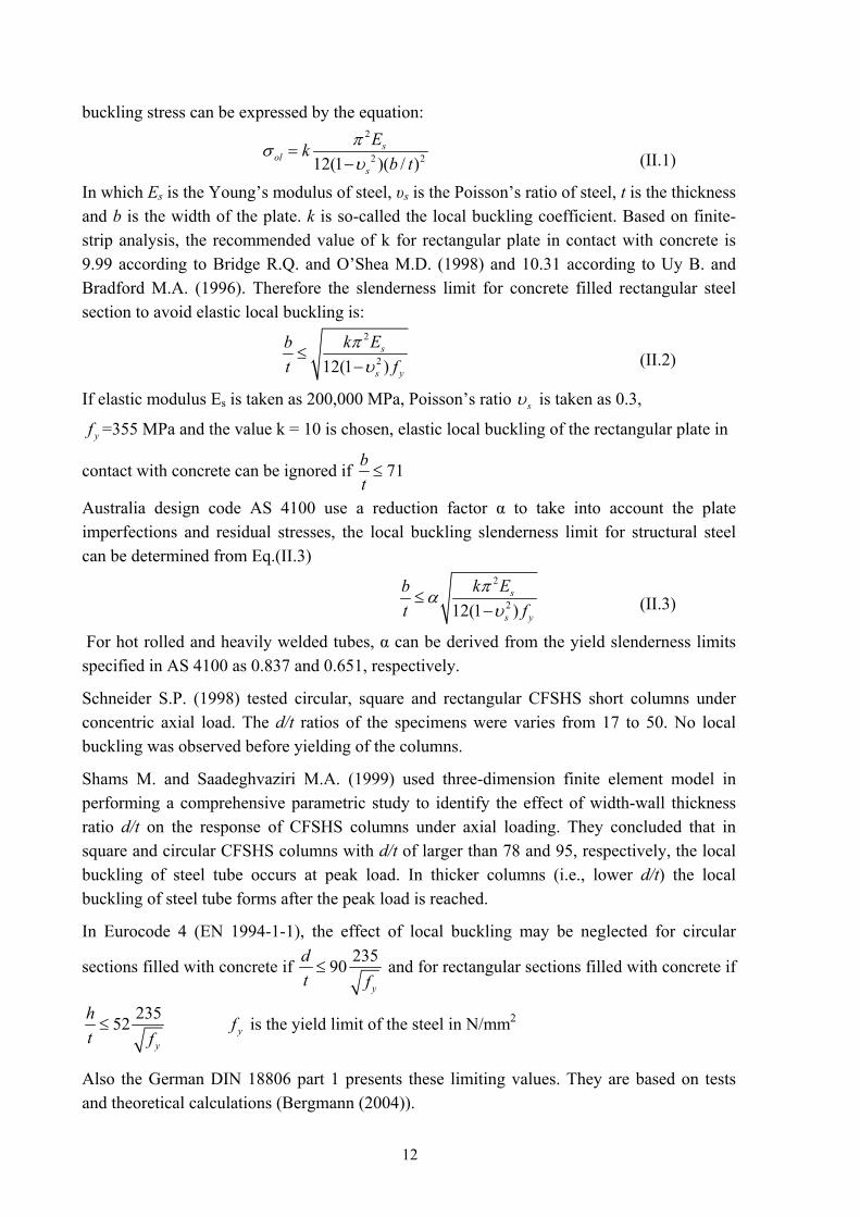
buckling stress can be expressed by the equation: 2
2 212(1 )( / )s
ols
Ekb t
πσυ
=−
(II.1)
In which Es is the Young’s modulus of steel, υs is the Poisson’s ratio of steel, t is the thickness and b is the width of the plate. k is so-called the local buckling coefficient. Based on finite-strip analysis, the recommended value of k for rectangular plate in contact with concrete is 9.99 according to Bridge R.Q. and O’Shea M.D. (1998) and 10.31 according to Uy B. and Bradford M.A. (1996). Therefore the slenderness limit for concrete filled rectangular steel section to avoid elastic local buckling is:
2
212(1 )s
s y
k Ebt f
πυ
≤−
(II.2)
If elastic modulus Es is taken as 200,000 MPa, Poisson’s ratio sυ is taken as 0.3,
yf =355 MPa and the value k = 10 is chosen, elastic local buckling of the rectangular plate in
contact with concrete can be ignored if 71bt≤
Australia design code AS 4100 use a reduction factor α to take into account the plate imperfections and residual stresses, the local buckling slenderness limit for structural steel can be determined from Eq.(II.3)
2
212(1 )s
s y
k Ebt f
παυ
≤−
(II.3)
For hot rolled and heavily welded tubes, α can be derived from the yield slenderness limits specified in AS 4100 as 0.837 and 0.651, respectively.
Schneider S.P. (1998) tested circular, square and rectangular CFSHS short columns under concentric axial load. The d/t ratios of the specimens were varies from 17 to 50. No local buckling was observed before yielding of the columns.
Shams M. and Saadeghvaziri M.A. (1999) used three-dimension finite element model in performing a comprehensive parametric study to identify the effect of width-wall thickness ratio d/t on the response of CFSHS columns under axial loading. They concluded that in square and circular CFSHS columns with d/t of larger than 78 and 95, respectively, the local buckling of steel tube occurs at peak load. In thicker columns (i.e., lower d/t) the local buckling of steel tube forms after the peak load is reached.
In Eurocode 4 (EN 1994-1-1), the effect of local buckling may be neglected for circular
sections filled with concrete if 23590y
dt f≤ and for rectangular sections filled with concrete if
23552y
ht f≤ yf is the yield limit of the steel in N/mm2
Also the German DIN 18806 part 1 presents these limiting values. They are based on tests and theoretical calculations (Bergmann (2004)).
12
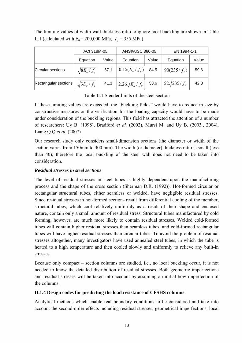
The limiting values of width-wall thickness ratio to ignore local buckling are shown in Table II.1 (calculated with Ea = 200,000 MPa, yf = 355 MPa)
ACI 318M-05 ANSI/AISC 360-05 EN 1994-1-1
Equation Value Equation Value Equation Value
Circular sections
67.1
84.5
59.6
Rectangular sections
41.1
53.6
42.3
0.15( / )a yE f8 /a yE f 90(235 / )Yf
52 235 / Yf3 /a yE f 2.26 /a YE f
Table II.1 Slender limits of the steel section
If these limiting values are exceeded, the “buckling fields” would have to reduce in size by constructive measures or the verification for the loading capacity would have to be made under consideration of the buckling regions. This field has attracted the attention of a number of researchers: Uy B. (1998), Bradford et al. (2002), Mursi M. and Uy B. (2003 , 2004), Liang Q.Q et al. (2007).
Our research study only considers small-dimension sections (the diameter or width of the section varies from 150mm to 300 mm). The width (or diameter) thickness ratio is small (less than 40); therefore the local buckling of the steel wall does not need to be taken into consideration.
Residual stresses in steel sections
The level of residual stresses in steel tubes is highly dependent upon the manufacturing process and the shape of the cross section (Sherman D.R. (1992)). Hot-formed circular or rectangular structural tubes, either seamless or welded, have negligible residual stresses. Since residual stresses in hot-formed sections result from differential cooling of the member, structural tubes, which cool relatively uniformly as a result of their shape and enclosed nature, contain only a small amount of residual stress. Structural tubes manufactured by cold forming, however, are much more likely to contain residual stresses. Welded cold-formed tubes will contain higher residual stresses than seamless tubes, and cold-formed rectangular tubes will have higher residual stresses than circular tubes. To avoid the problem of residual stresses altogether, many investigators have used annealed steel tubes, in which the tube is heated to a high temperature and then cooled slowly and uniformly to relieve any built-in stresses.
Because only compact – section columns are studied, i.e., no local buckling occur, it is not needed to know the detailed distribution of residual stresses. Both geometric imperfections and residual stresses will be taken into account by assuming an initial bow imperfection of the columns.
II.1.4 Design codes for predicting the load resistance of CFSHS columns
Analytical methods which enable real boundary conditions to be considered and take into account the second-order effects including residual stresses, geometrical imperfections, local
13
instability, crack of concrete, creep and shrinkage of concrete, confinement effects and yielding of structural steel and of reinforcement, lead to more realistic failure times and normally, to the most competitive design . However, the handling of such methods is quite time-consuming and requires expert knowledge. For practical design, “simple calculation models” have been developed, which make it possible to determine the load capacity of composite columns even without the help of a computer. These methods lead to a comprehensive design but are limited in application range.
Over the last three decades, different specific codes for the design of CFSHS columns have been written. Each of these codes is written so as to reflect the design philosophies and practices in the respective countries. A composite column may be treated in some codes as a steel column strengthened by concrete, whereas other codes may consider it as a reinforced concrete column with special reinforcement. Furthermore, the strength of a column may be evaluated as the sum of strengths of both components.
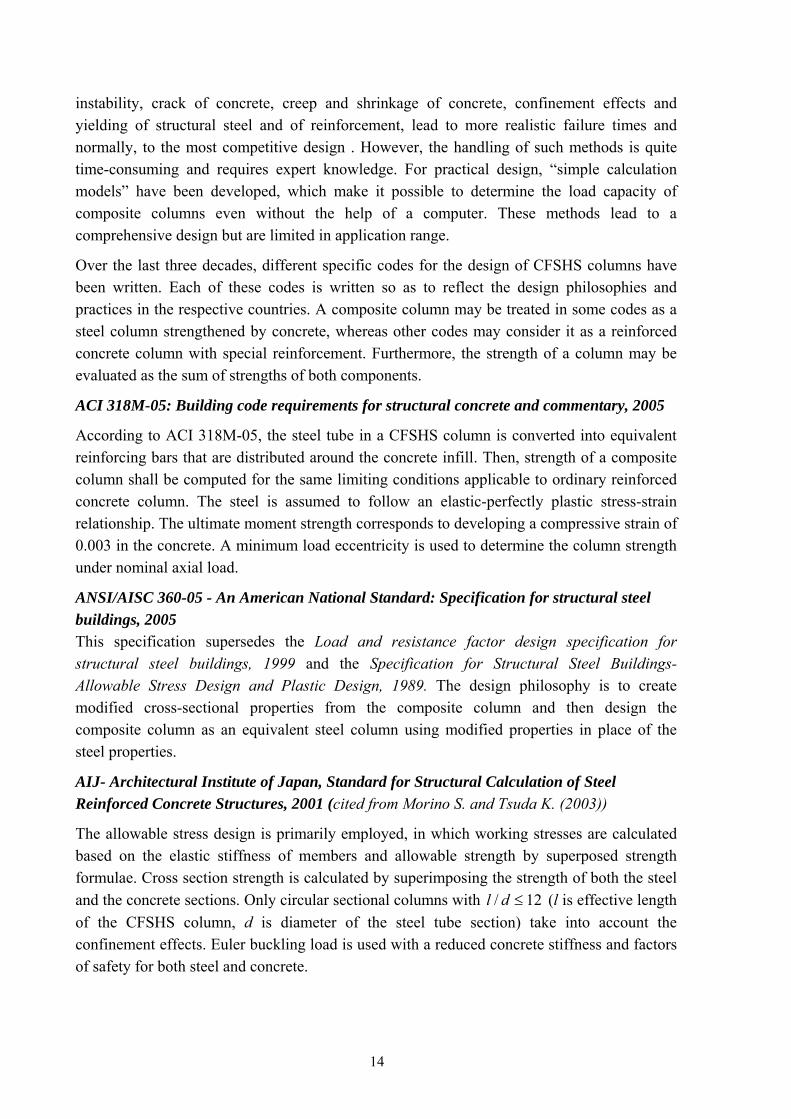
ACI 318M-05: Building code requirements for structural concrete and commentary, 2005
According to ACI 318M-05, the steel tube in a CFSHS column is converted into equivalent reinforcing bars that are distributed around the concrete infill. Then, strength of a composite column shall be computed for the same limiting conditions applicable to ordinary reinforced concrete column. The steel is assumed to follow an elastic-perfectly plastic stress-strain relationship. The ultimate moment strength corresponds to developing a compressive strain of 0.003 in the concrete. A minimum load eccentricity is used to determine the column strength under nominal axial load.
ANSI/AISC 360-05 - An American National Standard: Specification for structural steel buildings, 2005 This specification supersedes the Load and resistance factor design specification for structural steel buildings, 1999 and the Specification for Structural Steel Buildings- Allowable Stress Design and Plastic Design, 1989. The design philosophy is to create modified cross-sectional properties from the composite column and then design the composite column as an equivalent steel column using modified properties in place of the steel properties.
AIJ- Architectural Institute of Japan, Standard for Structural Calculation of Steel Reinforced Concrete Structures, 2001 (cited from Morino S. and Tsuda K. (2003))
The allowable stress design is primarily employed, in which working stresses are calculated based on the elastic stiffness of members and allowable strength by superposed strength formulae. Cross section strength is calculated by superimposing the strength of both the steel and the concrete sections. Only circular sectional columns with / 1l d 2≤ (l is effective length of the CFSHS column, d is diameter of the steel tube section) take into account the confinement effects. Euler buckling load is used with a reduced concrete stiffness and factors of safety for both steel and concrete.
14
Eurocode EN 1994-1-1 (2004)
Cross section strength is calculated by superimposing the strength of both the steel and the concrete sections. Enhancement of the concrete core from confinement is included for some specific cases. Column curves are used to determine the influence of slenderness (similar to most modern steel codes). For columns under combined compression and bending, the design method of Eurocode 4 uses an interaction diagram that can be calculated assuming full plasticity or more simply from a polygonal shape using specified points.
Comparison of the design codes
Some researchers have compared the ultimate loads of CFSHS columns obtained from experiments with the values calculated from existing design codes such as Eurocodes, American codes and Australian standards (Kilpatrick A.E. et al. (1997), Wang Y.C. (1999), O’Shea M.D., Bridge R.Q. (2000), Giakoumelis G. and Lam D. (2004), Zeghiche J. and K. Chaoui (2005), Hatzigeorgiou GD. (2007)).
O’Shea M.D., Bridge R.Q. compared the test results of short circular CFSHS columns to three design methods: Eurocode 4 (CEN 1992), ACI 318 (ACI 1989) and AS3600 (SAA 1994). The columns are under compression concentrically or with small eccentricities, with concrete strength up to 120 MPa. It was found that Eurocode 4 provided the best estimate of the specimen strength for axial and combined compression and bending. ((O’Shea M.D., Bridge R.Q. (2000)). This conclusion is also supported by Giakoumelis G. and Lam D. (2004), Liu D. et al. (2003)-(2005), Hatzigeorgiou GD. (2007)
Tests on long CFSHS columns were conducted by some researchers (Wang Y.C. (1999) and Zeghiche J. et al. (2005)). The test parameters were the column slenderness, the load eccentricity covering axially and eccentrically loaded columns, and the compressive concrete strength. A comparison of experimental failure loads with the predicted failure loads in accordance with the method described in EN 1994-1-1 showed good agreement for axially and eccentrically loaded columns.
After the review of the literature, Eurocode 4 (EN 1994-1-1) is adopted in this work for designing CFSHS columns. The method of EN 1994-1-1 is represented in part IV.1.1 of this thesis. But the scope of EN 1994-1-1 is limited to columns with longitudinal reinforcement ratio from 3% to 6% and circular hollow steel sections with additional I-section, the question arises whether this method is valid also for columns with high percentage of reinforcement (exceeding 6%) and other types of steel section containing another steel tube or profile (Figure II-4). This question will be discussed in chapter IV.
15
II.2 Self compacting concrete
II.2.1 Introduction
The development of self-compacting concrete (SCC) also referred to as “Self-Consolidating Concrete” has recently been one of the most important developments in building industry (Brouwers H.J.H and Radix H.J (2005)). It is a kind of concrete that can flow through and fill gaps of reinforcement and corners of moulds without any need for vibration and compaction during pouring process.
Due to its rheological properties, many advantages can be mentioned. SCC may contribute to a significant improvement of the quality of concrete structures and open up a new field for the application of concrete. SCC describes a concrete with the ability to compact itself only by means of its own weight without the requirement of vibration. It fills all recesses, reinforcement spaces and voids, even in high by reinforced concrete members. While flowing in the formwork SCC is able to deaerate almost completely. The use of SCC offers many benefits to the construction practice: the elimination of the compacting work results in reduced costs of placement, a shortening of the construction time and therefore in an improved productivity. The application of SCC also leads to a reduction of noise during casting, better working conditions and the possibility of expanding the placing times in inner city areas.
As disadvantages, SCC needs a high level of control on the quality of the used materials (sand, coarse aggregate, filler, superplasticitizer and cement) and on the adopted mix, since the concrete properties in fresh state can be altered presenting excessive fluidity, segregation or excess of cohesion. The stricter requirements on measuring, adjustments and control is however demanding, possibly excluding some of the less qualified and less well equipped concrete producers.
Often the material costs of SCC will be higher than the equivalent material costs of normal vibrated concrete. However when SCC is sensibly utilized, the reduction of costs by better productivity, shorter construction time and improved working conditions will compensate the higher material costs.
On the other hand, in densely reinforced sections, such as those in columns and beams in moment-resisting frames in seismic areas and in some repair sections, it is quite difficult to cast normal concrete and ensure that all spaces in the formwork is filled with concrete. The use of SCC is necessary in these cases. With SCC, new structural applications can be realized. Among them concrete filled HSS columns with small cross-section dimensions and dense reinforcement can be envisaged.
The basic components for the mix composition of SCC are the same as those used in conventional concrete. However, to obtain the requested properties of fresh SCC concrete, a higher proportion of ultra fine materials and the incorporation of chemical admixtures, in particularly an effective superplasticizer, are necessary. Classical filler materials are fly ash, limestone powder, blast furnace slag, silicafume and quartzite powder. A comparison of a
16
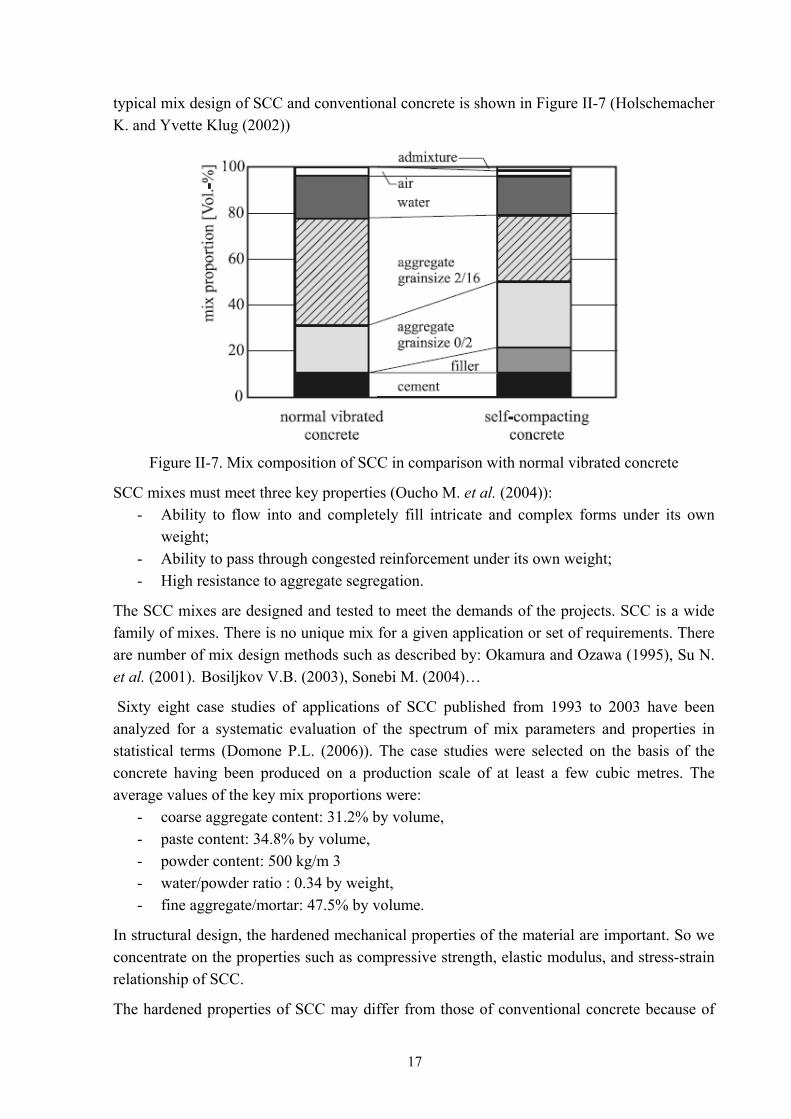
typical mix design of SCC and conventional concrete is shown in Figure II-7 (Holschemacher K. and Yvette Klug (2002))
Figure II-7. Mix composition of SCC in comparison with normal vibrated concrete
SCC mixes must meet three key properties (Oucho M. et al. (2004)): - Ability to flow into and completely fill intricate and complex forms under its own
weight; - Ability to pass through congested reinforcement under its own weight; - High resistance to aggregate segregation.
The SCC mixes are designed and tested to meet the demands of the projects. SCC is a wide family of mixes. There is no unique mix for a given application or set of requirements. There are number of mix design methods such as described by: Okamura and Ozawa (1995), Su N. et al. (2001). Bosiljkov V.B. (2003), Sonebi M. (2004)…
Sixty eight case studies of applications of SCC published from 1993 to 2003 have been analyzed for a systematic evaluation of the spectrum of mix parameters and properties in statistical terms (Domone P.L. (2006)). The case studies were selected on the basis of the concrete having been produced on a production scale of at least a few cubic metres. The average values of the key mix proportions were:
- coarse aggregate content: 31.2% by volume, - paste content: 34.8% by volume, - powder content: 500 kg/m 3 - water/powder ratio : 0.34 by weight, - fine aggregate/mortar: 47.5% by volume.
In structural design, the hardened mechanical properties of the material are important. So we concentrate on the properties such as compressive strength, elastic modulus, and stress-strain relationship of SCC.
The hardened properties of SCC may differ from those of conventional concrete because of
17
the better microstructure and homogeneity of SCC. The void ratio of SCC in the interfacial transition zone between cement paste and aggregate is essentially lower and the pores are distributed much more evenly (Holschemacher K. and Yvette Klug (2002)). But many researches in the literature indicate that the engineering properties of SCC do not significant differ from those of traditionally vibrated concrete.
II.2.2 Mechanical properties of hardened SCC at normal temperature
Many research studies in the literature indicated that the engineering properties of SCC do not significant differ from those of traditionally vibrated concrete:
- In the Brite EuRam project BE 96-3801 (2000), a wide variety of specimens (cubes, cylinders, prisms etc.) and full size columns and beams were cast from five types of concrete, so that direct comparisons of all aspects of hardened concrete could be made between the SCC and the reference mixes. It is indicated that the relationship between modulus cE and compressive strengths cf were similar for SCC and the reference
mixes. A relationship in the form of 0.5/( )c cE f has been widely reported, and all the
values of this ratio were close to the one recommended by ACI for structural calculations for normal weight tradition vibrated concrete.
- Persson B. (2001) has done an experimental and numerical study on mechanical properties of SCC and the corresponding properties of normal compacting concrete (NC). The results show that elastic modulus of SCC did not differ significantly from the elastic modulus of NC when the strength was held constant.
- Based on their own experimental investigations and a large number of test results taken from several references from the Proceeding of the International Workshop on Self-Compacting Concrete, Kochi University of Technology, Japan 1998, Holschemacher K. and Yvette Klug created a database with regard to hardened properties of SCC. The interpretation of this database should help determining whether the material properties of SCC are comparative with currently existing design rules according to CEB-FIP Model Code 90 (1990) and Eurocode 2: EN 1992-1-1 (2004). It was shown that at the same water-binder ratios the compressive strength and its time development are similar for SCC and normal vibrated concrete. The splitting tensile strength of SCC achieves frequently higher values, while the modulus of elasticity is clearly lower. However these deviations are situated in the range of tolerance usual for vibrated concrete. Therefore it is possible to design structural members made of SCC with the same design rules as for normal concrete. (Holschemacher K. et al. (2002), (Klug Y. (2003)). This inference is also supported by Domone (2007).
- European Guidelines for self compacting concrete (2005) represent a state of the art document addressed to those specifiers, designers, purchasers, producers and users who wish to enhance their expertise and use of SCC. The Guidelines have been using the wide range of experience and knowledge available to the European Project Group.
18
It is said that SCC and traditional vibrated concrete of similar compressive strength have comparable engineering properties and if there are differences, these are usually covered by the safe assumptions on which the design codes are based. The strength development of SCC is similar to normal vibrated concrete. After 28 days the reached compressive strength of SCC and normal vibrated concrete (NC) of similar composition do not differ significantly in the majority of the published test results. Because SCC often has higher paste content than traditional vibrated concrete, the E value may be somewhat lower but this should be adequately covered by the safe assumptions on which the formulas provided in EN 1992-1-1 are based. The suitability of EN 1992-1-1 for SCC is also supported by Cussigh F. (2007) and Lecrux S. et al. (2007).
- Dinakar P. et al. (2007) made SCCs with various volumes of fly ash. The mechanical properties of hardened concrete were determined and compared with five different mixtures of normal vibrated concrete. Test results indicated that the use of large proportion of fly ash reduced the elastic modulus of the self compacting concretes. The elastic modulus of SCC was about 8% less than that of normal concrete for an identical compressive strength. However this is only a problem in concrete that have a very high volume of fly ash. In the other cases, the modulus of concrete was almost comparable to that of normal concrete.
- Parra C. et al. (2007) conducted experimental work to study the compressive strength, the tensile strength and the modulus of elasticity of SCC and to compare the results obtained with those reported for traditional concrete. Several types of concrete were made, with different water/cement ratios and different types of cement. The results show that there are no significant differences between SCC and traditional concrete with regards to modulus of elasticity, although SCC tends to be slightly more deformable because of their higher paste content. The standard formulas that have traditionally been used to estimate the modulus of elasticity from compressive strength can be considered equally valid for SCC.
- Even the behaviour of SCC filled hollow structural steel columns has been investigated recently (Han L.H et al. (2004, 2005), Wang Y.F and Han L.H. (2005), Lachemi M. (2006), Qing-xiang W. et al (2006), Yu Z. et al. (2007), Yu Q. et al. (2008)). Using the mechanical model developed for normal concrete, the ultimate strength of the columns was predicted and compared with test results. Good agreement is obtained. It means that the mechanical model developed for normal concrete is acceptable for the analysis of hollow steel section columns filled with SCC. Further, comparisons are made with predicted section column strength using existing codes, such as AIJ (1997), AISC-LRFD (1999), BS5400 (1979), DL5085/T-1999, EC4-1994 and GJB4142-2000 (2001). It was found that, generally, these codes are acceptable for the design of ultimate strength of hollow steel section columns filled with SCC (Han L.H. et al. (2004a)).
19
After this review, it can be assumed that the mechanical properties of SCC at room temperature are similar to those of traditional concrete. From now on, the mechanical properties at room temperature of normal vibrated concrete will be used for SCC.
II.2.3 Mechanical properties of hardened SCC at elevated temperature
Most research studies on SCC under fire conditions relate to fire spalling of SCC (Boström L. (2002, 2007), Stegmaier M. et al. (2004), Noumowé A. et al. (2006), Ye G. et al. (2007)). In our study, concrete is encased by steel wall, therefore no spalling occurs. We concentrate only on mechanical properties of hardened SCC at elevated temperature.
A project of experimental studies of the mechanical performance of SCC under compressive loading at high temperatures was conducted at Lund Institute of Technology, Sweden (Persson B. (2003). The objectives of this project was to investigate mechanical performance under compressive loading at high temperature conditions of SCC that contains different amount of polypropylene fibres, different types of cement and air content, preconditioned either in the air or in water. The results of the studies enabled to compare the performance of SCC under compressive loading at fire temperature conditions with the corresponding properties of NC. Seven SCCs with water to cement ratio w/c = 0.4, 0.55 or 0.7 and one normal concrete with w/c=0.4 were studied for compressive strength at high temperature (200°C, 400°C and 800°C). Elastic modulus, ultimate strain at maximum strength, dynamic modulus and relative humidity were studied in parallel. The temperature development in the oven was much slower than the standard fire curve ISO 834 to avoid fire spalling. Results obtained at the laboratory showed that once spalling was avoided, SCC and NC behaved similarly at high temperature except at 800°C - at which SCC with limestone powder did not show any residual strength at all after cooling down to 20°C.
Persson B. (2004) investigated the hot and residual behaviours of 12 SCCs and 4 vibrated concretes with a compressive strength ranging from 40 to 88 MPa. The reference temperatures were 20, 200, 400, 600 and 800°C. As a rule, the heating and cooling rates were 4 and 1°C/minute respectively. At the reference temperature, all cylindrical specimens rested for 30 minutes before being tested in compression (“hot” tests) or being cooled (“residual” tests). The residual tests were carried out one week after cooling. The mean residual properties of the 10 SCC are plotted in a non-dimensional form, as a function of the reference temperature. For comparison, also strength decays of calcareous and siliceous concrete suggested by EN 1992-1-2 are plotted. He concluded that SCC tends to behave similarly to normal vibrated concrete and high strength concrete. This conclusion also supported in Bamonte P. et al. (2007). Noumowé A. et al. (2006) also conducted experimental work on the high-temperature behaviour of conventional vibrated high-strength concrete and self-compacting high-strength concrete. Concrete cylindrical specimens and prismatic specimens were subjected to a low heating rate of 0.5°C/min (up to 400°C) and a high heating rate according to International Standard Organization (ISO) 834 fire curve (up to 600°C). The experimental results show that the residual mechanical properties in reference to initial mechanical properties of self-compacting high-strength concretes were similar to that of conventional high-strength concrete.
20
After this review, it can be assumed that stress-strain relationship at elevated temperature of SCC is similar to that of traditional concrete. Experimental research described in chapter V will verify this assumption.
II.2.4 Thermal properties of SCC
The thermal properties that influence the temperature rise and distribution in a concrete structural section are specific density, thermal conductivity, specific heat, and derived from those, the thermal diffusivity. These properties depend on the type of aggregate and the composition of the concrete mix. So there may be differences between thermal properties of SCC and normal vibrated concrete.
Up to now, there is very little information on the thermal properties of SCC. Bamonte P. et al. (2007) calculated thermal diffusivity from the difference between two surface temperature sand that along one axis. They showed that SCC investigated in their study has diffusivity very close to that predicted by Eurocode 2 for ordinary vibrated concrete.
It has still to be confirmed that the thermal properties of SCC do not differ much from those of ordinary concrete. Using the values predicted by Eurocode 2, the simulations of hollow steel columns filled with self-compacting concrete under fire condition will be compared with results from tests performed at the University of Liege. It will be seen whether calibration are necessary.
II.3 Hollow steel columns filled with concrete under fire conditions
II.3.1 Introduction
In the event of a fire, a structural member is heated up by the energy supplied. From the onset of a fire, the rapidly rising ambient temperature induced a temperature gradient across the cross-section of the fire-exposed member, with higher temperature at points near the surface. As the result of the non-stationary (continuously changing) temperature situation, the thermal and mechanical properties of the construction material change, which in turn affects the load-bearing capacity and deformation behaviour of the structural member. The degree of resistance of a load-bearing member in a fire depends on the load level and the heating rate. The heating rate for a structural member is determined by the dimensions of the heated cross-section, the thermal properties of the materials used and the intensity of the fire.
To be able to realistically determine the structural behaviour by calculation, one need to know the fire exposure in the form of the temperature/time history of the ambient temperature, the boundary conditions at the surface of the structural member and the thermal transmission with its conduction, convection and radiation factors. With the aid of these values, the development of the non-stationary temperature fields within structural members can be calculated (thermal analysis). Knowing the temperature-dependent properties of materials, a “structural analysis” can be carried out, where the stresses, strains, and the displacements can be calculated at any time.
The main differences of fire design compared with normal temperature design are the following:
21

- Applied loads are smaller; - Internal forces are induced by thermal expansion; - Mechanical properties of materials are reduced at elevated temperatures; - Cross-sectional areas may be reduced by charring or spalling; - Smaller safety factors can be used on the material strength because of the low
probability of the event; - Different failure mechanisms need to be considered.
II.3.2 Behaviour of CFSHS columns under fire conditions
In CFSHS columns, concrete filling has been shown to improve the fire resistance. One reason is that the concrete increases the heat capacity of the column. More important however is that, when exposed to fire, a redistribution of load will occur in the column from the hot steel section to the relatively cold concrete core (ECCS (1998)).
Behaviour of CFSHS columns under fire conditions has been studied since the1980s. (Guyaux P. and Janss J. (1979), Kordina K. and Klingsch W. (1983), Lie T.T et al. (1988-1996), Kodur V.K.R (1999), Han L.H (2001), Zha X.X (2003), Renaux C. (2004), Ding J. and Wang Y.C. (2005-2008), for example. Data reported from literature can be used to illustrate the behaviour of the CFSHS columns under fire conditions. At room temperature, the load is carried by both the concrete and the steel. When the column is exposed to fire, the steel carries most of the load during the early stage because the steel section expands more rapidly than the concrete core. At higher temperatures, the steel section gradually yields as its strength decreases, and the column rapidly contracts at some point between 20 and 30 minute after exposed to fire (Kodur V.K.R (2007)). At this stage, the concrete filling starts carrying more and more of the load. The strength of concrete decreases with time and ultimately, when the column no longer supports the load, either it buckles or it fails in compression. The time at which the column fails determines its fire resistance. The behaviour of the column, after steel yields, is dependent on the properties of the concrete core: type of concrete, concrete strength and reinforcing steel area and location. The concrete core significantly contributes to an increased fire resistance of CFSHS columns. This contribution comes from the higher heat capacity of concrete and longer retention of concrete strength with time.
Zha X.X (2003) used DYNA3D, a three- dimensional nonlinear finite element transient analysis program, to investigate the behaviour of CFSHS columns in fire. Figure II-8 shows the variation with time of the average axial displacement of the end section of the column for four different applied loads when subjected to fire on four sides. P0
is the maximum compression load that the column can carry at ambient temperature. It can be seen from the figure that there are three stages that characterize the deformation history of the column. The first stage is the expansion stage in which the deformation is dominated by the thermal expansion and therefore the displacement increases with time. The second stage is the recovery stage in which the deformation is dominated by the compression due to the continuous softening of material induced by high temperatures and thus the displacement begins to decrease with time. The third stage is the collapse stage in which the strength of the concrete near to the surfaces submitted to fire is substantially reduced and the column can no
22
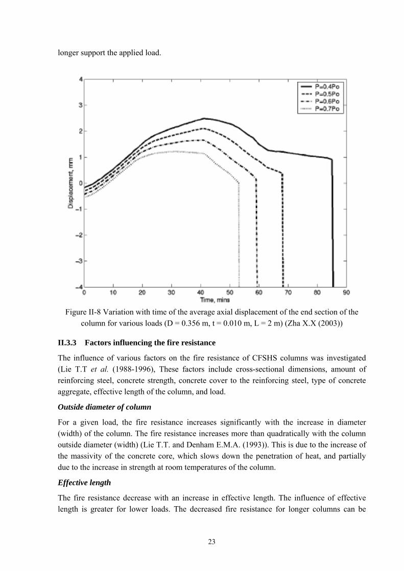
longer support the applied load.
Figure II-8 Variation with time of the average axial displacement of the end section of the
column for various loads (D = 0.356 m, t = 0.010 m, L = 2 m) (Zha X.X (2003))
II.3.3 Factors influencing the fire resistance
The influence of various factors on the fire resistance of CFSHS columns was investigated (Lie T.T et al. (1988-1996), These factors include cross-sectional dimensions, amount of reinforcing steel, concrete strength, concrete cover to the reinforcing steel, type of concrete aggregate, effective length of the column, and load.
Outside diameter of column
For a given load, the fire resistance increases significantly with the increase in diameter (width) of the column. The fire resistance increases more than quadratically with the column outside diameter (width) (Lie T.T. and Denham E.M.A. (1993)). This is due to the increase of the massivity of the concrete core, which slows down the penetration of heat, and partially due to the increase in strength at room temperatures of the column.
Effective length
The fire resistance decrease with an increase in effective length. The influence of effective length is greater for lower loads. The decreased fire resistance for longer columns can be
23
attributed to the increase of effective slenderness during the course of the fire which, in turn, reduces the load-carrying capacity.
Applied load
In the event of a fire, the applied loads are much lower than the maximum design load specified for normal temperature conditions, as different load combinations are used with a reduction of variable loads. The term “load ratio” is the ratio of the design loads on the structures during a fire to loads that would cause collapse at normal temperatures. In most practical cases the load ratio varies from 0.2 to 0.6. Of course a decrease of the load ratio increases the fire resistance.
Percentage of reinforcement
The presence of reinforcement in the concrete core will improve the flexural properties of the core and therefore improve the fire resistance, particularly where buckling stability and/or bending moments are major factors. At high temperatures, the external steel tube can no longer carry stresses, while the reinforcement protected by concrete can do, particularly tensile stresses.
Concrete strength The fire resistance of the column increases nearly linearly with the concrete strength. The influence is relatively greater for the higher loads than for the lower loads. The influence of concrete strength is also greater for shorter columns than for longer columns (Lie T.T. and Kodur V.K.R (1996)), since for short columns, there is no influence of buckling.
Concrete cover to reinforcing bars An increase of concrete cover increases the fire resistance of CFSHS columns. The effect of the concrete cover on the fire resistance of the column is greater for the columns with higher effective length, which can be explained by the essential role played by the reinforcements carrying tensile stresses when the column tends to buckle.
Bending moments and eccentricity When the flexural stiffness of the steel tube is lost, the bending resistance of the column is significantly reduced because of the relatively low value of the elastic modulus for concrete and its poor flexural strength compared to steel. The effect of accidental eccentricity and out of straightness of a column subjected to axial loads is not significant for short columns. However, this can become a significant factor for slender columns in fire. The presence of moments in the column produced by either end moments or by applied loads with eccentricity also has a significant effect on the fire stability.
II.3.4 Existing design methods for predicting the fire resistance of CFSHS columns
Calculating the fire resistance of a structure needs three separate consecutive steps. In the first step, the changing of surrounding air temperature with time (the “fire scenario”) is estimated. In the second step, the changing of temperature with time in the structure is estimated as the result of the time and space dependent heat transfer from hot air into the structure. A transient thermal analysis of the structure has to be performed in which the heat conduction problem is
24

solved, which is governed by the partial differential equation of the heat conduction. The effects of the heat radiation and the heat convection from air to the structure surface are accounted for via the boundary conditions. The final step consists in the determination of the time dependent mechanical response of the structure due to the simultaneous actions of mechanical and temperature effects.
Fire scenario The temperature development in a compartment during a fire is subjected first and foremost to the source of the fire (type, volume, and position), the ventilation conditions (size of openings for ingoing and out-going air, ventilation rate) and the compartment itself (geometry, insulating properties of surrounding structures). From the multitude of possible “natural fires” resulting from the above, the internationally accepted “standard temperature/time curve” reflecting the temperature/time development has been established as a common, standard thermal exposure for building and structures, although this temperature/time curve can reflect an actual fire only by approximation (Hosser D. et al. (1994)).
Several models of time-temperature relationship are available for the simulation of fires for design procedure. The most widely used test specifications are ASTM E199 and ISO 834. Other national standards include British Standard BS476 parts 20-23, Canadian Standard CAN/ULC-S101-M89 and Australian Standard AS 1530 part 4 (Buchanan A.H (2001)). Most national standards are based on either the ASTM E119 test or the ISO 834 test.
Thermal analysis When a CFSHS column is exposed to fire, because of the low diffusivity of concrete, a temperature gradient is expected on the cross section. For the majority of situations in which a column is exposed to fire that has uniform temperature along the column length, the column temperature may be assumed uniform over the height of the column. Thus, the temperature distribution within a CFSHS column cross-section can be simulated using a 2D model. The non-steady-state 2D temperature distribution within any cross-section is determined by the Fourier thermal conductivity equation:
2 2
( )é é
T Tk k Q c. . Tx y t
ρ∂ ∂ ∂+ + =
∂ ∂ ∂
where k is the thermal conductivity of the material, T is the temperature, Q is the amount of heat generated in the material per unit volume, ρ is the density, c is the heat capacity, and t is the time. x, y are the position coordinates. An analytical solution to this differential equation is possible only in very special cases. Nowadays there exists numbers of methods for calculating temperature in CFSHS columns exposed to fire: Lie T.T and Chabot M (1993c) used a finite difference method; Han L.H. used his finite element model; Renaud C. (2004) used the finite element code TASEF; Ding J. and Wang Y.C (2008) used the finite element analysis package ANSYS, Chung K. et al. (2008) used a finite deference method…
At the University of Liege, Franssen J.M. (2005) developed a non-linear code named SAFIR to analyze structures under elevated temperature conditions, although it can also be used to analyse structures under ambient conditions. In thermal analysis, SAFIR program uses
25
weighted function in Galerkin method to transform the heat transfer equation to a form suitable for finite element analysis. The discretisation for plane sections of all different shapes is possible by using triangular and/or quadrilateral elements. For each element the material can be defined separately. Any materials can be analysed if their thermal and physical properties at elevated temperatures are known. The variation of material properties with temperature as well as the evaporation of moisture can be considered.
For CFSHS columns, almost all research studies in literature use the following assumptions: • Conduction is the main heat transfer mechanism in the hollow steel section and the
concrete core. Convection and radiation act essentially for heat transfers from fire to hollow steel section;
• The effect of moisture (assumed uniformly distributed in the concrete) on the column temperatures is taken into account by assuming that all moisture evaporates, without any transfer, when the temperature reaches 100°C (or at another temperature within a narrow range with the heat of evaporation giving a corresponding change in the enthalpy-temperature curve). In the period of evaporation, all the heat supplied to an element is used for evaporation until the element is dry.
Some models assume a perfect thermal contact between steel tube and concrete core (Lie T.T and Chabot M (1993c), Han L.H., Ding J. and Wang Y.C (2008)). However, in a fire situation, an air gap may develop at the interface between the steel tube and the concrete core due to two reasons: the thermal expansion coefficient of steel is higher than that of concrete, leading to a higher radial expansion of the steel tube than the one of the concrete core; the difference in thermal expansion and strains in the longitudinal direction may overcome the bond between the steel tube and the concrete at the interface, which causes separation. This gap interrupts direct heat conduction between the hollow steel and the concrete core. The concrete core is further heated by the thermal radiation from the heated hollow steel section. The filling of the gap with steam further stops the heating of the concrete. It causes a delaying effect on the concrete heating. For this reason, the thermal interaction (gap) between hollow steel section and concrete core is taken into account in CIDECT research project 15Q (Renaud C. (2004)) by means of a fictitious thermal resistance assumed constant along the steel-concrete interface and independent of the temperature. The value of this thermal resistance (R) is equal to 0.01m2K/W. At 200C and 5000C the conductivity of concrete is 1.95 W/mK and 1.04 W/mK respectively, so this thermal resistance is equal to the thermal resistance of a layer of concrete with a thickness of 1.95 cm and 1.04 cm at 200C and 5000C respectively). This value was proposed to obtain a satisfactory correlation between numerical and test results. But in this CIDECT project the material thermal properties as a function of temperature have been taken to be in accordance with ENV 1994-1-2 (the pre-standard version of EC4). In the current version of EC4: EN 1994-1-2 (2004), there are some changes in concrete properties such as the thermal conductivity and the specific heat. In addition the emissivity coefficient for steel related to the surface of the member ( mε ) was changed:
0.5mε = according to ENV 1994-1-2 (1994), 0.7mε = according to EN 1994-1-2 (2004).
Therefore a new value of thermal resistance at the steel concrete interface needs to be found
26
when the current EC4- EN 1994 is used. This problem will be discussed in part III.2.
Structural analysis
For evaluating the fire resistance performance of structural members, two levels of analysis can be used. The first approach is the use of mathematical or numerical models that simulate the conditions to which structural members are subjected during their exposition to fire, called here “advanced calculation models”. The other approach is the use of design formulas, which are derived using the mathematical model and simplified to a form that can be incorporated in building codes, called “simple calculation models”. Advanced calculation models shall provide a realistic analysis of structures exposed to fire. They shall be based on fundamental physical behaviour in such a way as to lead to a reliable approximation of the expected behaviour of the relevant structural component under fire conditions. Compared with simple calculation models, advanced calculation models give an improved approximation of the actual structural behaviour under fire conditions. Simple calculation models lead to a comprehensive design but are limited in application range
In advanced calculation models, the nonlinear behaviour of a member under elevated temperature conditions can, in principle, be modelled using the finite-element method (Anderberg 1976, Schleich 1987, Okabe et al. 1991- cited from Poh K.W (1995)). Alternatively, as in the case of the methods described by Lie T.T. and Chabot M. (1993), Poh K.W. (1995), Han L.H. (2001a), moment-thrust-curvature relationships for member cross section can be used in conjunction with member equilibrium and compatibility equations. Only the methods that have been used to develop simplified calculation models for CFSHS columns in fire are listed hereafter:
• Lie T.T and Chabot M. (1993c) developed mathematical models for calculations of the fire resistance of compression members. The strength of members is determined by an iterative method based on a load-deflection or stability analysis. The curvature of the column is assumed to vary from pin-end to mid-height according to a linear relation. To determine the stress-strain distribution in the critical cross-section at mid-height, the cross-sectional area of the column is subdivided into a number of elements. Successive iterations are performed until the internal moment at the mid section is in equilibrium with the applied moment given by load × (deflection + eccentricity). The strength of the column decreases with the duration of fire exposure. The fire resistance is derived by determining the time at which the strength of the member becomes less than the load to which the column is subjected.
• Han L.H. (2001a) used the same approach as Lie’s but he assumed the shape of the deformation of the member to be a semi-sine curve. Due to the confining effect of the steel tube the increase in concrete strength is also taken into account by use of constraining factor in concrete stress-strain relations.
• Renaud C. et al. (2003, 2004) used SISMEF, a two-dimensional advanced calculation model developed at CTICM (Centre Technique Industriel de la Construction Metallique – France) to simulate the mechanical behaviour of CFSHS columns under
27
fire conditions. The model, based on displacement finite element methods with an Updated Lagrangian formulation, allows for geometrical and material non linearity combined with heating of the whole or a part of the section and column length. The model takes into account the interaction between the hollow steel section and concrete core by introducing a two nodes connection element with only one degree of freedom at each node corresponding to the discretisation of the distributed shear connection between steel and concrete.
• A non-linear computer code BoFIRE written by Schaumann P. and further developed by Upmeyer J. and Kettner F. was used to simulate composite columns in fire (Schaumann P. et al. (2006)). The program is based on the principle: ( ) ( )R t S t≥
where R(t) is resistance at time t, S(t) is effect of mechanical action at time of fire exposure t . The thermal response is first calculated. Then, according to the temperature distribution, the modification of the material properties caused by temperature can be computed. Subsequently, the mechanical response is calculated where deformation and remaining strength of the members are determined. These results are compared to the applied load on the column and it is verified whether the structure still has sufficient load-bearing capacity. This procedure is repeated for various time steps until the resistance of the member is less than the applied load.
• Some general purpose finite element code such as ABAQUS and ANSYS are used to model the behaviour of CFSHS columns in fire (Schaumann P. and Kettner F. (2004), Ding J. and Wang Y.C (2008), Hong Sangdo and Varma Amit H. (2009)).
The computer code SAFIR (Franssen J.M. (2005)), which is based on the Finite Element Method (FEM), has been built to study the behaviour of two and three-dimensional structures under both ordinary and fire conditions. SAFIR accommodates various elements for different idealizations, calculation procedures and material models incorporating stress-strain behaviour. Therefore, SAFIR can be used in simulating the behaviour of CFSHS columns under fire conditions.
There exist some simplified methods for calculating the resistance of CFSHS column under fire conditions:
• Lie T.T et al. (1994-1996) used mathematic models described above to predict the fire resistance of CFSHS columns. The numerical procedure, contained in the mathematical model, was programmed for computer processing. The validity of the computer programs was established by comparing the results of the models to test data (Lie T.T et al. (1994-1995)). With this method, hollow steel columns filled with plain concrete, steel fibre- reinforced concrete and bar-reinforced concrete were studied and simplified equations for evaluating the fire resistance of these columns have been developed with the restricted limits: percentage of main reinforcing bars from 1.5 % to 5.0 %, effective length of column from 2.0m to 4.5 m.
28
• Han L.H. et al. conducted experimental studies on fire resistance of hollow steel section columns filled with plain concrete (Han L.H. et al. (2003a,b,c)). After verifying the mathematical model suggested by one of the authors (Han L.H. (2001a), they analysed the influence of several parameters, such as fire duration time, sectional dimension, load eccentricity ratio, and strength of steel and concrete. A formula for the strength index (the ratio of the ultimate strength corresponding to the fire resistance time (t) to the ultimate strength of the column at normal temperature) is obtained by using regression analysis. This formula can be applied without the need of computer but it uses a lot of empirical coefficients based on experiments; and it can be used only in the case of plain concrete filled hollow steel sections.
• Since the old version of the European pre-standard ENV-1994-1-2 (1994), there exist two methods for calculating CFSHS columns in fire: the tabular method and the calculation method. The tabular method, which is based on the test results and directly gives the column fire resistance depending on the applied load and the section-size, is obviously easy to use; however, the user’s choice is restricted to the few available loading cases and section sizes (Wang Y.C. (2000)). On the other hand, the calculation method is generally applicable. However, the user has to implement numerical method procedure to first find out the non-uniform temperature distributions in the column section and then to evaluate the load bearing capacity based on the non-uniform distribution of material strength and stiffness. A simple calculation model for calculating CFSHS columns in fire is given in annex G of the European pre-standard ENV-1994-1-2 (1994) and updated in Annex H- current European standard EN-1994-1-2 (2004). For a given field of temperature, the ultimate buckling load is determined by means of a procedure similar to the one developed by Guiaux and Janss for composite hollow sections at ordinary temperature, except that the method is adapted by using temperature-dependent generalized stress-strain relationships for the steel section, reinforcement and concrete. This determination is based on the following principle: the axial buckling load at increasing temperature corresponds to the Euler critical load according to Engesser’s concept of tangent modulus applied to various materials at different temperatures. So an effective value of flexural stiffness for the composite column can be derived from the stress-strain relationships, assuming an equal elongation for all materials and neglecting any effect of self-equilibrated stresses due to differential thermal elongations. This method is limited in application range: percentage of reinforcing steel less than 5%, buckling length less than 4.5 m.
• A research project of CIDECT (Comité International pour le Développment et l’Etude de la Construction Tubulaire) has been done to improve and extend the simple calculation method of EC4 part 1.2, Annex G (ENV 1994-1-2) for fire resistance of unprotected concrete filled hollow columns (Renaud C. (2004). The model SISMEF has been used to perform a wide series of numerical simulations for many values of significant parameters affecting the performance of CFSHS columns such as buckling length, fire duration, cross-section size… Using the same type of buckling approach
29
proposed at room temperature in Eurocode 4 (but modifying material properties at elevated temperatures) a new formulation of the buckling curves has been proposed for axially loaded CFSHS columns subject to standard fire exposure. The load bearing capacity of a concrete filled hollow steel section in axial compression and in the fire situation, should be divided into two successive steps:
- Firstly, the calculation of the temperature distribution in the composite cross-section after a given duration of fire exposure, this calculation being made easier with the help of given tabulated data.
- Secondly, the calculation of the design axial buckling load for the field of temperature previously obtained, using the plastic resistance to axial compression of the composite cross-section reduced by means of a coefficient to take into account buckling at elevated temperatures.
The limitation of this method is this calculation model should only be applied for square or circular sections with percentage of reinforcement less than 5%.
• Schaumann P. and Kettner F. (2004) used the code BoFIRE to develop a catalogue for ultimate load of composite columns (hollow section with an inner I- or X-section) for fire resistance class R60, R90 and R120. The ultimate loads are given for tube diameters from 273 mm to 711 mm with some values of column length, concrete grade, loading eccentricities… Like for a tabulated data, the user’s choice is restricted to the few available parameters.
From the literature review it can be seen that the simplified models for the fire resistance of concrete filled HSS columns with small cross-section dimensions and dense reinforcement (where self-compacting concrete is needed) is still not available. The development of a simplified model for that type of CFSHS columns will be presented in chapter VI.
II.4 Material properties at elevated temperatures
The “high-temperature properties” of materials are defined by the temperature-dependent changes in their characteristic thermal values (density, specific heat capacity, thermal conductivity) and their characteristic mechanical values (strength, Young’s modulus, stress-strain diagram, thermal strain). For the materials concrete and steel, these properties are known from research studies made in the past (Schneider U. (1986,1988), Anderberg Y. (1988), Twilt L. (1988), Cooke G.M.E. (1988), Bazant Z.P. and Kaplan M.F. (1996), Dotreppe J.C. et al. (1997), Poh K.W. (2001), Li L.Y and Purkiss J. (2005), … Mathematically they are defined as “material laws” in the form of functional calculation values. Some physical and chemical reactions of materials such as decohesion and chemical decomposition due to increased temperatures are not explicitly considered. Typical stress-strain relationships for structural steel and concrete at elevated temperatures are shown on Figure II-9 and Figure II-10, respectively.
30

Figure II-9. Stress-strain curves for typical-hot rolled steel at elevated temperatures (Buchanan A.H. (2001))
Figure II-10. Stress-strain relationship for concrete at elevated temperatures (Buchanan A.H.)
“Material laws” for concrete and steel material can be found in: Eurocodes models, AIJ models, Ramberg-Osgood curve-fitting equations (Saab H.A. et al. (1991)), Lie‘s material model (1994), Han’s material model (Han L.H (2001)). An overview of concrete properties at elevated temperatures is presented in the references Xiao J. et al. (2003) and Youssef M.A. et al. (2007). Chung K. et al. (2008) presented the review and comparison of four material models including Lie’s material models, Yin’s material model (Yin J. et al. (2006)), Eurocode model and AIJ model. They also validated and employed these four material models on both numerical heat transfer analysis and nonlinear thermal stress analysis of CFSHS columns at elevated temperatures. The results of the numerical analysis were compared with the
31

32
experimental results. It is concluded that in general, the temperatures, fire resistance and axial deformation calculated from Eurocodes model are in reasonably good agreement with the experimental results. Kyungsoo Chung et al. (2008) also supported this inference.
Also, many research works used Eurocodes models: (Huang Z.F et al. (2008), Schaumann P. and Kettner F. (2004), Yu J.T et al. (2007), Ding J. and Wang Y.C (2005,2008), Huang Z. et al. (2000)), Renaud C. et al. (2003, 2004). In this study Eurocodes material models have also been chosen in simulations. The detailed material properties can be found in Appendix 1.