Embed Size (px)
Citation preview

EQUILIBRIUM OF RIGID BODIES

Equilibrium
• A body in equilibrium is at rest or can translate with constant velocity
𝐹 = 0
𝑀 = 0

EQUILIBRIUM IN TWO DIMENSIONSCase where the force system acting on a rigid body lies in or may be projected onto a single plane

Free-Body Diagrams
• Successful application of the equations of equilibrium requires a complete specification of all the known and unknown external forces that act on the body.
Free-Body Diagrams
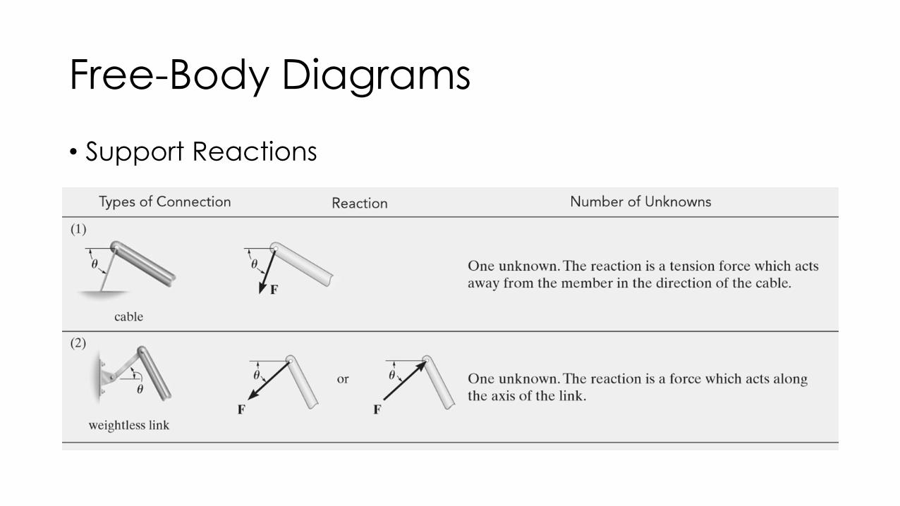
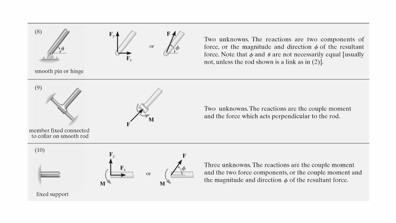
• Support Reactions


Procedure for Analysis
• To construct a free-body diagram for a rigid body or any group of bodies considered as a single system, the following steps should be performed:
• Draw Outlined Shape.
• Show All Forces and Couple Moments.
• Identify Each Loading and Give Dimensions.

Important Points
• No equilibrium problem should be solved without first drawing the free-body diagram
• If a support prevents translation of a body in a particular direction, then the support exerts a force on the body in that direction.
• If rotation is prevented , then the support exerts a couple moment on the body.
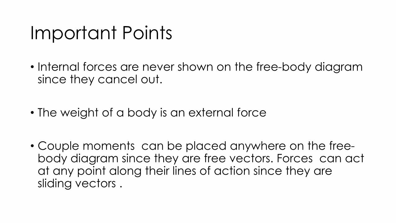
Important Points
• Internal forces are never shown on the free-body diagram since they cancel out.
• The weight of a body is an external force
• Couple moments can be placed anywhere on the free-body diagram since they are free vectors. Forces can act at any point along their lines of action since they are sliding vectors .

Example 1
• Draw the free-body diagram of the uniform beam. The beam has a mass of 100 kg.
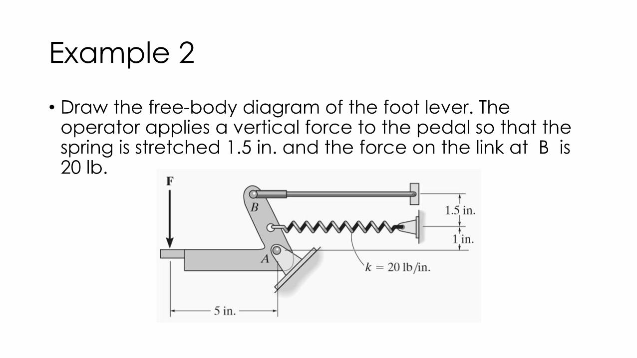
Example 2
• Draw the free-body diagram of the foot lever. The operator applies a vertical force to the pedal so that the spring is stretched 1.5 in. and the force on the link at B is 20 lb.

Example 3
• Two smooth pipes, each having a mass of 300 kg, are supported by the forked tines of the tractor. Draw the free-body diagrams for each pipe and both pipes together.
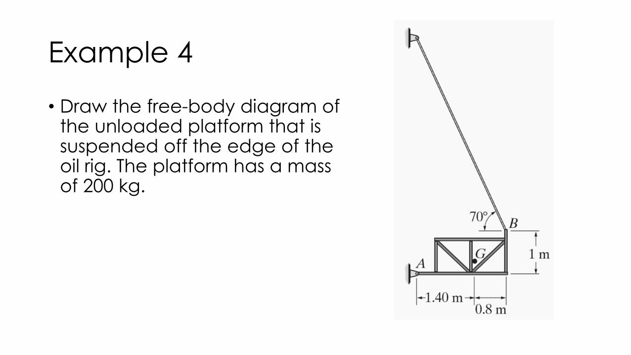
Example 4
• Draw the free-body diagram of the unloaded platform that is suspended off the edge of the oil rig. The platform has a mass of 200 kg.

Activity
• Draw the free-body diagram of the dumpster D of the truck, which has a mass of 2.5 Mg and a center of gravity at G. It is supported by a pin at A and a pin-connected hydraulic cylinder BC.
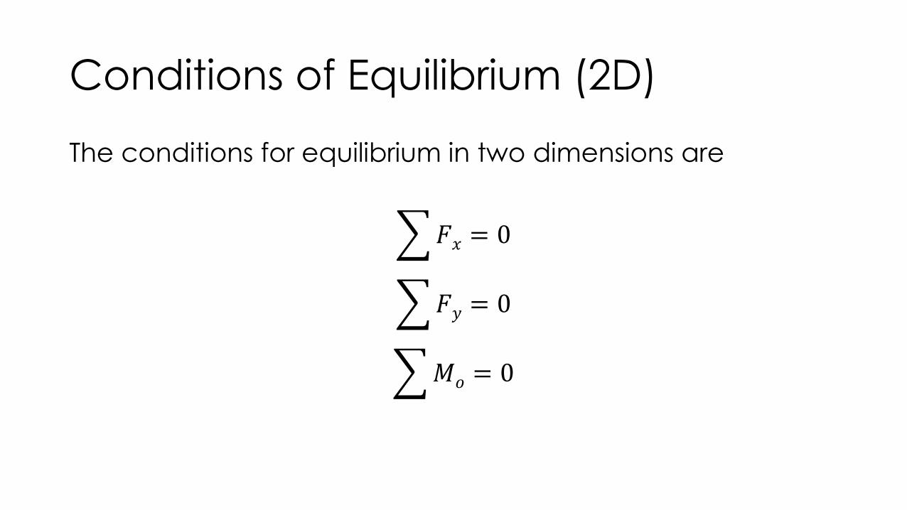
Conditions of Equilibrium (2D)
The conditions for equilibrium in two dimensions are
𝐹𝑥 = 0
𝐹𝑦 = 0
𝑀𝑜 = 0

Procedure for Analysis
• Free-Body Diagram. • Establish the x, y coordinate axes in any suitable orientation. • Draw an outlined shape of the body. • Show all the forces and couple moments acting on the body. • The sense of a force or couple moment having an unknown magnitude can be assumed . • Indicate the dimensions of the body necessary for computing the moments of forces.
• Equations of Equilibrium.• Apply the moment equation of equilibrium about a point that lies at the intersection of the
lines of action of two unknown forces. • Orient the x and y axes along lines that will provide the simplest resolution of the forces
into their x and y components. • If the solution of the equilibrium equations yields a negative scalar for a force or couple
moment magnitude, this indicates that the sense is opposite to that which was assumed on the free-body diagram.

Example 1
• Determine the horizontal and vertical components of reaction on the beam caused by the pin at B and the rocker at A. Neglect the weight of the beam.

Example 2
• The cord supports a force of 100 lband wraps over the frictionless pulley. Determine the tension in the cord at C and the horizontal and vertical components of reaction at pin A .

Example 3
• The box wrench is used to tighten the bolt at A . If the wrench does not turn when the load is applied to the handle, determine the torque or moment applied to the bolt and the force of the wrench on the bolt.

Activity
• Determine the horizontal and vertical components of reaction on the member at the pin A , and the normal reaction at the roller B.