Embed Size (px)
Citation preview

8/13/2019 EtherNet-IP Modules in Logix5000 Control Systems User Manual
http://slidepdf.com/reader/full/ethernet-ip-modules-in-logix5000-control-systems-user-manual 1/230
EtherNet/IP Modules in Logix5000 ControlSystems
Catalog Numbers 1756-ENBT, 1756-EN2F, 1756-EN2T, 1756-EN2TR,1756-EN2TXT, 1768-ENBT, 1769-L23E-QB1B, 1769-L23E-QBFC1B, 1769-
L32E, 1769-L35E, 1783-ETAP, 1783-ETAP1F, 1783-ETAP2F, 1794-AENT, 20-COMM-E, 22-COMM-E, 1734-AENT, 1734-AENTR
User Manual

8/13/2019 EtherNet-IP Modules in Logix5000 Control Systems User Manual
http://slidepdf.com/reader/full/ethernet-ip-modules-in-logix5000-control-systems-user-manual 2/230
Important User Information
Solid state equipment has operational characteristics differing from those of electromechanical equipment. Safety Guidelinesfor the Application, Installation and Maintenance of Solid State Controls (publication SGI-1.1 available from your local RockwellAutomation sales office or online at http://www.rockwellautomation.com/literature/) describes some important differencesbetween solid state equipment and hard-wired electromechanical devices. Because of this difference, and also because of thewide variety of uses for solid state equipment, all persons responsible for applying this equipment must satisfy themselves thateach intended application of this equipment is acceptable.
In no event will Rockwell Automation, Inc. be responsible or liable for indirect or consequential damages resulting from the useor application of this equipment.
The examples and diagrams in this manual are included solely for illustrative purposes. Because of the many variables andrequirements associated with any particular installation, Rockwell Automation, Inc. cannot assume responsibility or liability foractual use based on the examples and diagrams.
No patent liability is assumed by Rockwell Automation, Inc. with respect to use of information, circuits, equipment, or softwaredescribed in this manual.
Reproduction of the contents of this manual, in whole or in part, without written permission of Rockwell Automation, Inc., isprohibited.
Throughout this manual, when necessary, we use notes to make you aware of safety considerations.
Allen-Bradley, ArmorPOINT, CompactLogix, ControlLogix, DriveLogix, FLEX I/O, FlexLogix, Guard I/O, Logix5000, POINT I/O, Rockwell Automation, RSLinx, RSLogix 5000, Stratix 6000, Stratix 8000, and TechConnect are trademarks of Rockwell Automation, Inc.
Trademarks not belonging to Rockwell Automation are property of their respective companies.
WARNINGIdentifies information about practices or circumstances that can cause an explosion in a hazardous environment,
which may lead to personal injury or death, property damage, or economic loss.
IMPORTANT Identifies information that is critical for successful application and understanding of the product.
ATTENTION
Identifies information about practices or circumstances that can lead to personal injury or death, property damage,
or economic loss. Attentions help you identify a hazard, avoid a hazard, and recognize the consequence
SHOCK HAZARD
Labels may be on or inside the equipment, for example, a drive or motor, to alert people that dangerous voltage may
be present.
BURN HAZARDLabels may be on or inside the equipment, for example, a drive or motor, to alert people that surfaces may reach
dangerous temperatures.

8/13/2019 EtherNet-IP Modules in Logix5000 Control Systems User Manual
http://slidepdf.com/reader/full/ethernet-ip-modules-in-logix5000-control-systems-user-manual 3/230
3Publication ENET-UM001I-EN-P - January 2010 3
Summary of Changes
Introduction This release of this document contains new and updated information. To findnew and updated information, look for change bars, as shown next to thisparagraph.
Updated Information The document contains these changes.
Additional less significant changes have been made throughout the document.Change bars mark all changes.
Topic Page
Description of 1783-ETAP1F and 1783-ETAP2F EtherNet/IPFiber Taps to the EtherNet/IP Overview chapter
13
Updated Rockwell Automation Products with EmbeddedSwitch Technology section
58
1783-ETAP, 1783-ETAP1F, and 1783-ETAP2F EtherNet/IP TapStatus Indicators
187

8/13/2019 EtherNet-IP Modules in Logix5000 Control Systems User Manual
http://slidepdf.com/reader/full/ethernet-ip-modules-in-logix5000-control-systems-user-manual 4/230
4 Publication ENET-UM001I-EN-P - January 2010
Summary of Changes
Notes:

8/13/2019 EtherNet-IP Modules in Logix5000 Control Systems User Manual
http://slidepdf.com/reader/full/ethernet-ip-modules-in-logix5000-control-systems-user-manual 5/230
5Publication ENET-UM001I-EN-P - January 2010 5
Table of Contents
Preface Purpose of This Manual. . . . . . . . . . . . . . . . . . . . . . . . . . . . . . . . . . . . . 11 Who Should Use This Publication . . . . . . . . . . . . . . . . . . . . . . . . . . . . 11
Chapter 1
EtherNet/IP Overview Introduction . . . . . . . . . . . . . . . . . . . . . . . . . . . . . . . . . . . . . . . . . . . . . . 13
1756-ENBT Module . . . . . . . . . . . . . . . . . . . . . . . . . . . . . . . . . . . . . . 15 Additional Resources . . . . . . . . . . . . . . . . . . . . . . . . . . . . . . . . . . 15
1756-EN2F, 1756-EN2T, 1756-EN2TR, and1756-EN2TXT Modules . . . . . . . . . . . . . . . . . . . . . . . . . . . . . . . . . . . . 15
Additional Resources . . . . . . . . . . . . . . . . . . . . . . . . . . . . . . . . . . . 161768-ENBT Module . . . . . . . . . . . . . . . . . . . . . . . . . . . . . . . . . . . . . . . 17
Additional Resources . . . . . . . . . . . . . . . . . . . . . . . . . . . . . . . . . . 171769-L23E-QB1B, 1769-L23E-QBFC1B Packaged Controllers . . . . 17
Additional Resources . . . . . . . . . . . . . . . . . . . . . . . . . . . . . . . . . . 171769-L32E and 1769-L35E Controllers . . . . . . . . . . . . . . . . . . . . . . . . 18
Additional Resources . . . . . . . . . . . . . . . . . . . . . . . . . . . . . . . . . . 18
1783-ETAP, 1783-ETAP1F, and 1783-ETAP2FEtherNet/IP Taps . . . . . . . . . . . . . . . . . . . . . . . . . . . . . . . . . . . . . . . . . 18
Additional Resources . . . . . . . . . . . . . . . . . . . . . . . . . . . . . . . . . . 191788-ENBT Module . . . . . . . . . . . . . . . . . . . . . . . . . . . . . . . . . . . . . . . 19
Additional Resources . . . . . . . . . . . . . . . . . . . . . . . . . . . . . . . . . . 191794-AENT Adapter . . . . . . . . . . . . . . . . . . . . . . . . . . . . . . . . . . . . . . 20
Additional Resources . . . . . . . . . . . . . . . . . . . . . . . . . . . . . . . . . . . 201734-AENT and 1734-AENTR Adapters . . . . . . . . . . . . . . . . . . . . . . 20
Additional Resources . . . . . . . . . . . . . . . . . . . . . . . . . . . . . . . . . . . 201738-AENT and 1738-AENTR Adapters . . . . . . . . . . . . . . . . . . . . . . 21
Additional Resources . . . . . . . . . . . . . . . . . . . . . . . . . . . . . . . . . . . 21
20-COMM-E Module . . . . . . . . . . . . . . . . . . . . . . . . . . . . . . . . . . . . . . 21 Additional Resources . . . . . . . . . . . . . . . . . . . . . . . . . . . . . . . . . . . . 21
22-COMM-E Module . . . . . . . . . . . . . . . . . . . . . . . . . . . . . . . . . . . . . . 22 Additional Resources . . . . . . . . . . . . . . . . . . . . . . . . . . . . . . . . . . . 22
EtherNet/IP Communication Modules in a Control System . . . . . . . 23Installing Communication Modules or Other Devices onthe EtherNet/IP Network . . . . . . . . . . . . . . . . . . . . . . . . . . . . . . . 24
Safety I/O in EtherNet/IP Control Systems . . . . . . . . . . . . . . . . . . . . 24I/O Module Overview . . . . . . . . . . . . . . . . . . . . . . . . . . . . . . . . . . 24Guard I/O Catalog Numbers . . . . . . . . . . . . . . . . . . . . . . . . . . . . . 25CIP Safety in EtherNet/IP Safety Architectures . . . . . . . . . . . . . . 26
Bridge Across Networks . . . . . . . . . . . . . . . . . . . . . . . . . . . . . . . . . . . . 27EtherNet/IP Network Specifications . . . . . . . . . . . . . . . . . . . . . . . . . . 30
Chapter 2
Configure a Workstation to
Operate on an EtherNet/IP
Network
Introduction . . . . . . . . . . . . . . . . . . . . . . . . . . . . . . . . . . . . . . . . . . . . . . 33Configure the Ethernet Communication Driver inRSLinx Software. . . . . . . . . . . . . . . . . . . . . . . . . . . . . . . . . . . . . . . . . . . 34

8/13/2019 EtherNet-IP Modules in Logix5000 Control Systems User Manual
http://slidepdf.com/reader/full/ethernet-ip-modules-in-logix5000-control-systems-user-manual 6/230
6 Publication ENET-UM001I-EN-P - January 2010
Table of Contents
Chapter 3
Configure Stratix Switches Introduction . . . . . . . . . . . . . . . . . . . . . . . . . . . . . . . . . . . . . . . . . . . . . . 37Select a Switch . . . . . . . . . . . . . . . . . . . . . . . . . . . . . . . . . . . . . . . . . . . . 37Set Up the Hardware . . . . . . . . . . . . . . . . . . . . . . . . . . . . . . . . . . . . . . . 38
Switch Features. . . . . . . . . . . . . . . . . . . . . . . . . . . . . . . . . . . . . . . . . . . . 38 Additional Resources . . . . . . . . . . . . . . . . . . . . . . . . . . . . . . . . . . . . . . . 39
Chapter 4
Configure an EtherNet/IP Module
to Operate on the Network
Introduction . . . . . . . . . . . . . . . . . . . . . . . . . . . . . . . . . . . . . . . . . . . . . . 41Determine Network Parameters . . . . . . . . . . . . . . . . . . . . . . . . . . . . . . 41Set the IP Network Address . . . . . . . . . . . . . . . . . . . . . . . . . . . . . . . . . 43 Assign Network Parameters via the BOOTP/DHCP Utility . . . . . . . 45Other Methods to Assign Network Parameters . . . . . . . . . . . . . . . . . . 47
Configure the Module with RSLinx Software . . . . . . . . . . . . . . . . 48Configure Your Module with RSLogix 5000 Software . . . . . . . . . 50Use DHCP Software to Set the IP Address . . . . . . . . . . . . . . . . . . 51
Duplicate IP Address Detection . . . . . . . . . . . . . . . . . . . . . . . . . . . . . . 51Detection of Duplicate IP Addresses . . . . . . . . . . . . . . . . . . . . . . . 53
IP Address Swapping. . . . . . . . . . . . . . . . . . . . . . . . . . . . . . . . . . . . . . . 53DNS Addressing . . . . . . . . . . . . . . . . . . . . . . . . . . . . . . . . . . . . . . . . . . 54Use EtherNet/IP Modules in a Logix5000Controller Application . . . . . . . . . . . . . . . . . . . . . . . . . . . . . . . . . . . . . . 55
Chapter 5
Configure a Supervisor on a
Device-level Ring Network
Introduction . . . . . . . . . . . . . . . . . . . . . . . . . . . . . . . . . . . . . . . . . . . . . . 57
Rockwell Automation Products with EmbeddedSwitch Technology . . . . . . . . . . . . . . . . . . . . . . . . . . . . . . . . . . . . . . . . . 58
Features Common to Products with EmbeddedSwitch Technology. . . . . . . . . . . . . . . . . . . . . . . . . . . . . . . . . . . . . . 59Supervisor Node . . . . . . . . . . . . . . . . . . . . . . . . . . . . . . . . . . . . . . . 61Ring Node . . . . . . . . . . . . . . . . . . . . . . . . . . . . . . . . . . . . . . . . . . . . 63
Construct the Physical Network . . . . . . . . . . . . . . . . . . . . . . . . . . . . . . 63Configure Supervisor Nodes on a DLR Network . . . . . . . . . . . . . . . . 64
Configure a Ring Supervisor in RSLogix 5000Programming Software . . . . . . . . . . . . . . . . . . . . . . . . . . . . . . . . . . 65Enable Ring Supervisor in RSLogix 5000
Programming Software . . . . . . . . . . . . . . . . . . . . . . . . . . . . . . . . . . 68Configure and Enable a Ring Supervisor in RSLinx ClassicCommunication Software . . . . . . . . . . . . . . . . . . . . . . . . . . . . . . . . 71
Complete the Physical Connections of the Network . . . . . . . . . . . . . . 74 Verify Supervisor Configuration . . . . . . . . . . . . . . . . . . . . . . . . . . . . . . 75 Troubleshoot DLR Network Issues . . . . . . . . . . . . . . . . . . . . . . . . . . . 75

8/13/2019 EtherNet-IP Modules in Logix5000 Control Systems User Manual
http://slidepdf.com/reader/full/ethernet-ip-modules-in-logix5000-control-systems-user-manual 7/230
Publication ENET-UM001I-EN-P - January 2010 7
Table of Contents
Chapter 6
Control I/O Introduction . . . . . . . . . . . . . . . . . . . . . . . . . . . . . . . . . . . . . . . . . . . . . . 77Set Up the Hardware . . . . . . . . . . . . . . . . . . . . . . . . . . . . . . . . . . . . . . . 77 Add Distributed I/O . . . . . . . . . . . . . . . . . . . . . . . . . . . . . . . . . . . . . . . 78
Add a Module. . . . . . . . . . . . . . . . . . . . . . . . . . . . . . . . . . . . . . . . . . 79Select a Communication Format . . . . . . . . . . . . . . . . . . . . . . . . . . . . . . 82
Choosing a Direct or Rack-optimized Connection . . . . . . . . . . . . 83Ownership . . . . . . . . . . . . . . . . . . . . . . . . . . . . . . . . . . . . . . . . . . . . 86Select a Remote Adapter . . . . . . . . . . . . . . . . . . . . . . . . . . . . . . . . 87
Set the Requested Packet Interval (RPI) . . . . . . . . . . . . . . . . . . . . . . . . 88 Access Distributed I/O . . . . . . . . . . . . . . . . . . . . . . . . . . . . . . . . . . . . . 90 Additional Resources . . . . . . . . . . . . . . . . . . . . . . . . . . . . . . . . . . . . . . . 92
Chapter 7
Interlocking and Data Transfer
Between Controllers
Introduction . . . . . . . . . . . . . . . . . . . . . . . . . . . . . . . . . . . . . . . . . . . . . . 93Set Up the Hardware . . . . . . . . . . . . . . . . . . . . . . . . . . . . . . . . . . . . . . . 93
Logix5000 Controller Combinations . . . . . . . . . . . . . . . . . . . . . . . 94 Tag Guidelines for Produced or Consumed Data . . . . . . . . . . . . . . . . 95
Terminology . . . . . . . . . . . . . . . . . . . . . . . . . . . . . . . . . . . . . . . . . . . 95Connections for Produced and Consumed Tags . . . . . . . . . . . . . . . . . 96 Produce a Tag . . . . . . . . . . . . . . . . . . . . . . . . . . . . . . . . . . . . . . . . . . . . 98
Configure the Produced Tag. . . . . . . . . . . . . . . . . . . . . . . . . . . . . . 98Consume Data Produced by Another Controller. . . . . . . . . . . . . . . . 100
Add the Producer Controller to the Consumer’sI/O Configuration . . . . . . . . . . . . . . . . . . . . . . . . . . . . . . . . . . . . . 100Create the Consumed Tag . . . . . . . . . . . . . . . . . . . . . . . . . . . . . . . 103
Guidelines for Message (MSG) Instructions. . . . . . . . . . . . . . . . . . . . 105Connections for Messages . . . . . . . . . . . . . . . . . . . . . . . . . . . . . . . . . . 106
Cache Message Connections . . . . . . . . . . . . . . . . . . . . . . . . . . . . . 106Enter Message Logic . . . . . . . . . . . . . . . . . . . . . . . . . . . . . . . . . . . . . . 107
Add the EtherNet/IP Module to the Local Controller’sI/O Configuration . . . . . . . . . . . . . . . . . . . . . . . . . . . . . . . . . . . . . 107Enter a Message . . . . . . . . . . . . . . . . . . . . . . . . . . . . . . . . . . . . . . . 110
Configure a MSG Instruction . . . . . . . . . . . . . . . . . . . . . . . . . . . . . . . 111Communicate with PLC-5 or SLC Processors . . . . . . . . . . . . . . . . . . 115
Converting between INTs and DINTs . . . . . . . . . . . . . . . . . . . . 115
Mapping Tags. . . . . . . . . . . . . . . . . . . . . . . . . . . . . . . . . . . . . . . . . 116Receive MSGs from PLC-5 or SLC 500 Processors . . . . . . . . . . 118

8/13/2019 EtherNet-IP Modules in Logix5000 Control Systems User Manual
http://slidepdf.com/reader/full/ethernet-ip-modules-in-logix5000-control-systems-user-manual 8/230
8 Publication ENET-UM001I-EN-P - January 2010
Table of Contents
Chapter 8
Send Email Introduction . . . . . . . . . . . . . . . . . . . . . . . . . . . . . . . . . . . . . . . . . . . . . 119EtherNet/IP Module as an Email Client . . . . . . . . . . . . . . . . . . . . . . 119Send Email Via a Controller-initiated Message Instruction . . . . . . . . 121
Create String Tags . . . . . . . . . . . . . . . . . . . . . . . . . . . . . . . . . . . . . 121Enter the Ladder Logic . . . . . . . . . . . . . . . . . . . . . . . . . . . . . . . . . 125Configure the MSG Instruction That Identifies theMail Relay Server . . . . . . . . . . . . . . . . . . . . . . . . . . . . . . . . . . . . . . 125Configure the MSG Instruction That Contains theEmail Text . . . . . . . . . . . . . . . . . . . . . . . . . . . . . . . . . . . . . . . . . . . 127
Enter Email Text . . . . . . . . . . . . . . . . . . . . . . . . . . . . . . . . . . . . . . . . . 129Possible Email Status Codes . . . . . . . . . . . . . . . . . . . . . . . . . . . . . . . . 129
Chapter 9
Communicate with PanelView
Terminals
Introduction . . . . . . . . . . . . . . . . . . . . . . . . . . . . . . . . . . . . . . . . . . . . . 131Set Up the Hardware . . . . . . . . . . . . . . . . . . . . . . . . . . . . . . . . . . . . . . 131
Logix5000 Controller Combinations . . . . . . . . . . . . . . . . . . . . . . 132Connections to PanelView Terminals . . . . . . . . . . . . . . . . . . . . . . . . . 132 Add a PanelView Terminal . . . . . . . . . . . . . . . . . . . . . . . . . . . . . . . . . 133Organize Controller Data for a PanelView Terminal. . . . . . . . . . . . . 136Connections to RSView Applications . . . . . . . . . . . . . . . . . . . . . . . . . 136
Chapter 10
Monitor Diagnostics Introduction . . . . . . . . . . . . . . . . . . . . . . . . . . . . . . . . . . . . . . . . . . . . . 137Diagnostic Web Pages . . . . . . . . . . . . . . . . . . . . . . . . . . . . . . . . . . . . . 138
Network Settings . . . . . . . . . . . . . . . . . . . . . . . . . . . . . . . . . . . . . . . . . 141Explicit Message Connections. . . . . . . . . . . . . . . . . . . . . . . . . . . . . . . 142I/O Connections . . . . . . . . . . . . . . . . . . . . . . . . . . . . . . . . . . . . . . . . . 143Ethernet Statistics. . . . . . . . . . . . . . . . . . . . . . . . . . . . . . . . . . . . . . . . . 144
Chapter 11
Troubleshoot an EtherNet/IP
Module
Introduction . . . . . . . . . . . . . . . . . . . . . . . . . . . . . . . . . . . . . . . . . . . . . 147 Access Web Browser Support . . . . . . . . . . . . . . . . . . . . . . . . . . . . . . . 147
Diagnostic Overview Statistics . . . . . . . . . . . . . . . . . . . . . . . . . . . 149Message Connections . . . . . . . . . . . . . . . . . . . . . . . . . . . . . . . . . . 152I/O Connections . . . . . . . . . . . . . . . . . . . . . . . . . . . . . . . . . . . . . . 153
Ethernet Statistics . . . . . . . . . . . . . . . . . . . . . . . . . . . . . . . . . . . . . 153Switch Considerations . . . . . . . . . . . . . . . . . . . . . . . . . . . . . . . . . . . . . 157
Internet Group Multicast Protocol . . . . . . . . . . . . . . . . . . . . . . . . 157 Virtual Local Area Networks . . . . . . . . . . . . . . . . . . . . . . . . . . . . 158Port Mirroring . . . . . . . . . . . . . . . . . . . . . . . . . . . . . . . . . . . . . . . . 159

8/13/2019 EtherNet-IP Modules in Logix5000 Control Systems User Manual
http://slidepdf.com/reader/full/ethernet-ip-modules-in-logix5000-control-systems-user-manual 9/230
Publication ENET-UM001I-EN-P - January 2010 9
Table of Contents
Chapter 12
USB Serial Communication Introduction . . . . . . . . . . . . . . . . . . . . . . . . . . . . . . . . . . . . . . . . . . . . . 161Set Up the Hardware . . . . . . . . . . . . . . . . . . . . . . . . . . . . . . . . . . . . . . 161Configure a Module Via the USB Port . . . . . . . . . . . . . . . . . . . . . . . . 162
Set Up a USB Driver . . . . . . . . . . . . . . . . . . . . . . . . . . . . . . . . . . . 163Flash Upgrade Firmware through a USB Port . . . . . . . . . . . . . . . . . . 165
Appendix A
Status Indicators Introduction . . . . . . . . . . . . . . . . . . . . . . . . . . . . . . . . . . . . . . . . . . . . . 1671756-ENBT EtherNet/IP Module Status Indicators. . . . . . . . . . . . . 1691756-EN2F EtherNet/IP Module Status Indicators . . . . . . . . . . . . . 1711756-EN2T EtherNet/IP Module Status Indicators . . . . . . . . . . . . . 1731756-EN2TR EtherNet/IP Module Status Indicators. . . . . . . . . . . . 1751756-EN2TXT ControlLogix-XT EtherNet/IP BridgeModule Status Indicators . . . . . . . . . . . . . . . . . . . . . . . . . . . . . . . . . . . 1771769-L23E-QB1B and 1769-L23E-QBFC1B ControllersStatus Indicators . . . . . . . . . . . . . . . . . . . . . . . . . . . . . . . . . . . . . . . . . . 178
I/O Status Indicators. . . . . . . . . . . . . . . . . . . . . . . . . . . . . . . . . . . 1821769-L32E and 1769-L35E Controllers Status Indicators. . . . . . . . . 1831768-ENBT Module Status Indicators . . . . . . . . . . . . . . . . . . . . . . . . 1851783-ETAP, 1783-ETAP1F, and 1783-ETAP2FEtherNet/IP Tap Status Indicators . . . . . . . . . . . . . . . . . . . . . . . . . . 1871788-ENBT EtherNet/IP Daughtercard Status Indicators. . . . . . . . 1891734-AENT and 1734-AENTR EtherNet/IPPOINT I/O Adapter Status Indicators . . . . . . . . . . . . . . . . . . . . . . . 1921738-AENTR ArmorPOINT I/O 2-port EtherNet/IP Adapter Status Indicators. . . . . . . . . . . . . . . . . . . . . . . . . . . . . . . . . . . 1951794-AENT EtherNet/IP FLEX I/O AdapterStatus Indicators . . . . . . . . . . . . . . . . . . . . . . . . . . . . . . . . . . . . . . . . . . 19920-COMM-E Module Status Indicators . . . . . . . . . . . . . . . . . . . . . . . 20122-COMM-E Module Status Indicators . . . . . . . . . . . . . . . . . . . . . . . 205
Appendix B
Fiber Cable and LC Connector Introduction . . . . . . . . . . . . . . . . . . . . . . . . . . . . . . . . . . . . . . . . . . . . . 209Specifications . . . . . . . . . . . . . . . . . . . . . . . . . . . . . . . . . . . . . . . . . . . . 209
Appendix CEtherNet/IP Network Connections Introduction . . . . . . . . . . . . . . . . . . . . . . . . . . . . . . . . . . . . . . . . . . . . . 213
CIP Connections . . . . . . . . . . . . . . . . . . . . . . . . . . . . . . . . . . . . . . . . . 213 TCP Connections . . . . . . . . . . . . . . . . . . . . . . . . . . . . . . . . . . . . . . . . . 214Multicast Address Limit. . . . . . . . . . . . . . . . . . . . . . . . . . . . . . . . . . . . 215Requested Packet Interval (RPI) . . . . . . . . . . . . . . . . . . . . . . . . . . . . . 215

8/13/2019 EtherNet-IP Modules in Logix5000 Control Systems User Manual
http://slidepdf.com/reader/full/ethernet-ip-modules-in-logix5000-control-systems-user-manual 10/230
10 Publication ENET-UM001I-EN-P - January 2010
Table of Contents
Appendix D
EtherNet/IP Network Overview Introduction . . . . . . . . . . . . . . . . . . . . . . . . . . . . . . . . . . . . . . . . . . . . . 217Ethernet Protocols . . . . . . . . . . . . . . . . . . . . . . . . . . . . . . . . . . . . . . . . 217
Use of the Common Industrial Protocol (CIP) . . . . . . . . . . . . . . 218
Configuration Requirements . . . . . . . . . . . . . . . . . . . . . . . . . . . . . . . . 219IP Address . . . . . . . . . . . . . . . . . . . . . . . . . . . . . . . . . . . . . . . . . . . 219Gateways . . . . . . . . . . . . . . . . . . . . . . . . . . . . . . . . . . . . . . . . . . . . 220Subnet Mask. . . . . . . . . . . . . . . . . . . . . . . . . . . . . . . . . . . . . . . . . . 221
Manual Configuration on an Ethernet Switch . . . . . . . . . . . . . . . . . . 222Change Ports on an Ethernet Switch . . . . . . . . . . . . . . . . . . . . . . . . . 222 Additional Resources . . . . . . . . . . . . . . . . . . . . . . . . . . . . . . . . . . . . . . 222
Index

8/13/2019 EtherNet-IP Modules in Logix5000 Control Systems User Manual
http://slidepdf.com/reader/full/ethernet-ip-modules-in-logix5000-control-systems-user-manual 11/230
11Publication ENET-UM001I-EN-P - January 2010 11
Preface
Purpose of This Manual This manual describes how you can use EtherNet/IP modules with yourLogix5000 controller and communicate with various devices on the Ethernetnetwork.
Who Should UseThis Publication
You should use this manual if you program applications that use Ethernet withone of these Logix5000 controllers:
• CompactLogix controller
• ControlLogix controller
• FlexLogix controller
You should also understand:
• networking concepts.
• RSLogix 5000 programming software.
• RSLinx Classic programming software.

8/13/2019 EtherNet-IP Modules in Logix5000 Control Systems User Manual
http://slidepdf.com/reader/full/ethernet-ip-modules-in-logix5000-control-systems-user-manual 12/230
12 Publication ENET-UM001I-EN-P - January 2010
Preface
Notes:

8/13/2019 EtherNet-IP Modules in Logix5000 Control Systems User Manual
http://slidepdf.com/reader/full/ethernet-ip-modules-in-logix5000-control-systems-user-manual 13/230
13Publication ENET-UM001I-EN-P - January 2010 13
Chapter 1
EtherNet/IP Overview
Introduction The Logix5000 family of controllers offers several EtherNet/IP
communication modules.
Topic Page
1756-ENBT Module 15
1756-EN2F, 1756-EN2T, 1756-EN2TR, and 1756-EN2TXT Modules 15
1768-ENBT Module 17
1769-L23E-QB1B, 1769-L23E-QBFC1B Packaged Controllers 17
1769-L32E and 1769-L35E Controllers 18
1783-ETAP, 1783-ETAP1F, and 1783-ETAP2F EtherNet/IP Taps 18
1788-ENBT Module 19
1794-AENT Adapter 20
1734-AENT and 1734-AENTR Adapters 20
1738-AENT and 1738-AENTR Adapters 21
20-COMM-E Module 21
22-COMM-E Module 22
EtherNet/IP Communication Modules in a Control System 23
Safety I/O in EtherNet/IP Control Systems 24
Bridge Across Networks 27
EtherNet/IP Network Specifications 30
8/13/2019 EtherNet-IP Modules in Logix5000 Control Systems User Manual
http://slidepdf.com/reader/full/ethernet-ip-modules-in-logix5000-control-systems-user-manual 14/230
14 Publication ENET-UM001I-EN-P - January 2010
Chapter 1 EtherNet/IP Overview
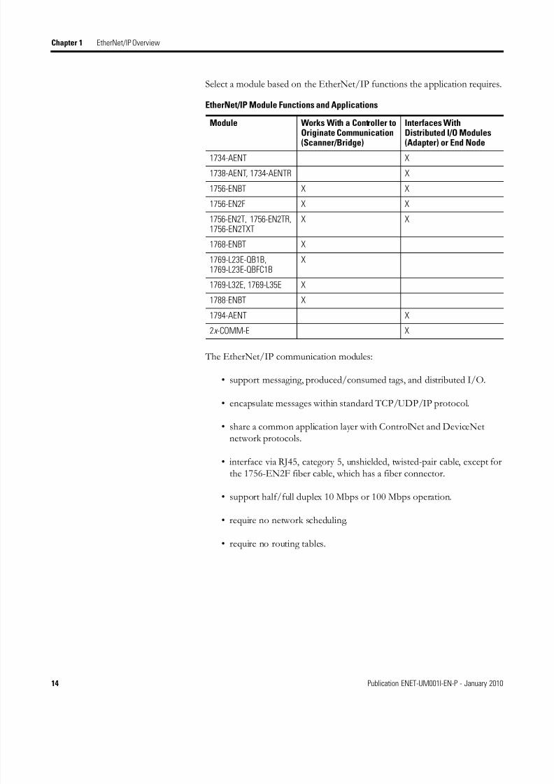
Select a module based on the EtherNet/IP functions the application requires.
The EtherNet/IP communication modules:
• support messaging, produced/consumed tags, and distributed I/O.
• encapsulate messages within standard TCP/UDP/IP protocol.
• share a common application layer with ControlNet and DeviceNetnetwork protocols.
• interface via RJ45, category 5, unshielded, twisted-pair cable, except forthe 1756-EN2F fiber cable, which has a fiber connector.
• support half/full duplex 10 Mbps or 100 Mbps operation.
• require no network scheduling.
• require no routing tables.
EtherNet/IP Module Functions and Applications
Module Works With a Controller to
Originate Communication(Scanner/Bridge)
Interfaces With
Distributed I/O Modules(Adapter) or End Node
1734-AENT X
1738-AENT, 1734-AENTR X
1756-ENBT X X
1756-EN2F X X
1756-EN2T, 1756-EN2TR,1756-EN2TXT
X X
1768-ENBT X
1769-L23E-QB1B,1769-L23E-QBFC1B
X
1769-L32E, 1769-L35E X
1788-ENBT X
1794-AENT X
2x -COMM-E X

8/13/2019 EtherNet-IP Modules in Logix5000 Control Systems User Manual
http://slidepdf.com/reader/full/ethernet-ip-modules-in-logix5000-control-systems-user-manual 15/230
Publication ENET-UM001I-EN-P - January 2010 15
EtherNet/IP Overview Chapter 1
1756-ENBT Module The 1756-ENBT module operates either as an interface for a ControlLogixcontroller to communicate with other devices over an EtherNet/IP networkor as an adapter for 1756 I/O modules on an EtherNet/IP network. Thismodule supports:
• control of I/O.• communication via produced/consumed tags and MSG instructions.
• communication with HMI.
• configuration and programming, such as uploading and downloading.
• an adapter for 1756 I/O modules.
• a web server to provide diagnostic and status information.
Additional Resources
1756-EN2F, 1756-EN2T,1756-EN2TR, and1756-EN2TXT Modules
The following modules perform the same functions as the 1756-ENBTmodule but with twice the capacity for demanding applications.
• 1756-EN2F ControlLogix EtherNet/IP fiber module
• 1756-EN2T ControlLogix EtherNet/IP bridge module• 1756-EN2TR ControlLogix EtherNet/IP 2-port module
• 1756-EN2TXT ControlLogix-XT EtherNet/IP module
All modules support:
• control of I/O.
• communication via produced/consumed tags and MSG instructions.
• communication with HMI.
• configuration and programming, such as uploading and downloading.
• an adapter for 1756 I/O modules.
• USB serial communication, enabling a laptop or workstation to accessand program a Logix5000 controller. For more information, see thechapter USB Port Connection.
• a web server to provide diagnostic and status information.
• rotary switches for quick IP address configuration.
Resource Description
1756-ENBT ControlLogix EtherNet/IP Bridge ModuleInstallation Instructions, publication 1756-IN019
Details how to install the module and provides technical specifications.
1756-ENBT ControlLogix Redundancy System Revision 15User Manual, publication 1756-UM523
Details how to use and maintain a ControlLogix redundancy system.
1756-EN2T

8/13/2019 EtherNet-IP Modules in Logix5000 Control Systems User Manual
http://slidepdf.com/reader/full/ethernet-ip-modules-in-logix5000-control-systems-user-manual 16/230
16 Publication ENET-UM001I-EN-P - January 2010
Chapter 1 EtherNet/IP Overview
The 1756-EN2F module only supports an LC fiber connector to supportadditional applications. For more information on LC fiber connectors, seeFiber Cable and LC Connector on page 209.
The 1756-EN2TR module only supports connection of a ControlLogixsystem to a linear or device level ring (DLR) network.
The 1756-EN2TXT module only supports use of the module in extremetemperatures. The module is capable of operating in temperatures from
-25…70° C (-13…158° F).
Additional Resources
Resource Description
1756-EN2T ControlLogix EtherNet/IP Bridge ModuleInstallation Instructions, publication 1756-IN603
Details how to install the module and provides technical specifications.
1756-EN2TR ControlLogix EtherNet/IP 2-port ModuleInstallation Instructions , publication 1756-IN612
Details how to install the module and provides technical specifications.
1756-EN2F ControlLogix EtherNet/IP Fiber ModuleInstallation Instructions, publication 1756-IN606
Details how to install the fiber module and provides technicalspecifications.
1756-EN2TXT ControlLogix-XT EtherNet/IP Bridge ModuleInstallation Instructions, publication 1756-IN635
Details how to install the fiber module and provides technicalspecifications.
8/13/2019 EtherNet-IP Modules in Logix5000 Control Systems User Manual
http://slidepdf.com/reader/full/ethernet-ip-modules-in-logix5000-control-systems-user-manual 17/230
Publication ENET-UM001I-EN-P - January 2010 17
EtherNet/IP Overview Chapter 1
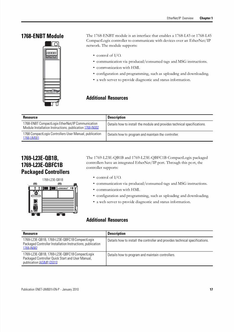
1768-ENBT Module The 1768-ENBT module is an interface that enables a 1768-L43 or 1768-L45CompactLogix controller to communicate with devices over an EtherNet/IPnetwork. The module supports:
• control of I/O.
• communication via produced/consumed tags and MSG instructions.
• communication with HMI.
• configuration and programming, such as uploading and downloading.
• a web server to provide diagnostic and status information.
Additional Resources
1769-L23E-QB1B,1769-L23E-QBFC1B
Packaged Controllers
The 1769-L23E-QB1B and 1769-L23E-QBFC1B CompactLogix packagedcontrollers have an integrated EtherNet/IP port. Through this port, thecontroller supports:
• control of I/O.
• communication via produced/consumed tags and MSG instructions.
• communication with HMI.
• configuration and programming, such as uploading and downloading.
• a web server to provide diagnostic and status information.
Additional Resources
Resource Description
1768-ENBT CompactLogix EtherNet/IP CommunicationModule Installation Instructions, publication 1768-IN002
Details how to install the module and provides technical specifications.
1768 CompactLogix Controllers User Manual, publication1768-UM001
Details how to program and maintain the controller.
1769-L23E-QB1B
Resource Description
1769-L23E-QB1B, 1769-L23E-QBFC1B CompactLogixPackaged Controller Installation Instructions, publication1769-IN082
Details how to install the controller and provides technical specifications.
1769-L23E-QB1B, 1769-L23E-QBFC1B CompactLogixPackaged Controller Quick Start and User Manual,publication IASIMP-QS010
Details how to program and maintain controllers.
8/13/2019 EtherNet-IP Modules in Logix5000 Control Systems User Manual
http://slidepdf.com/reader/full/ethernet-ip-modules-in-logix5000-control-systems-user-manual 18/230
18 Publication ENET-UM001I-EN-P - January 2010
Chapter 1 EtherNet/IP Overview
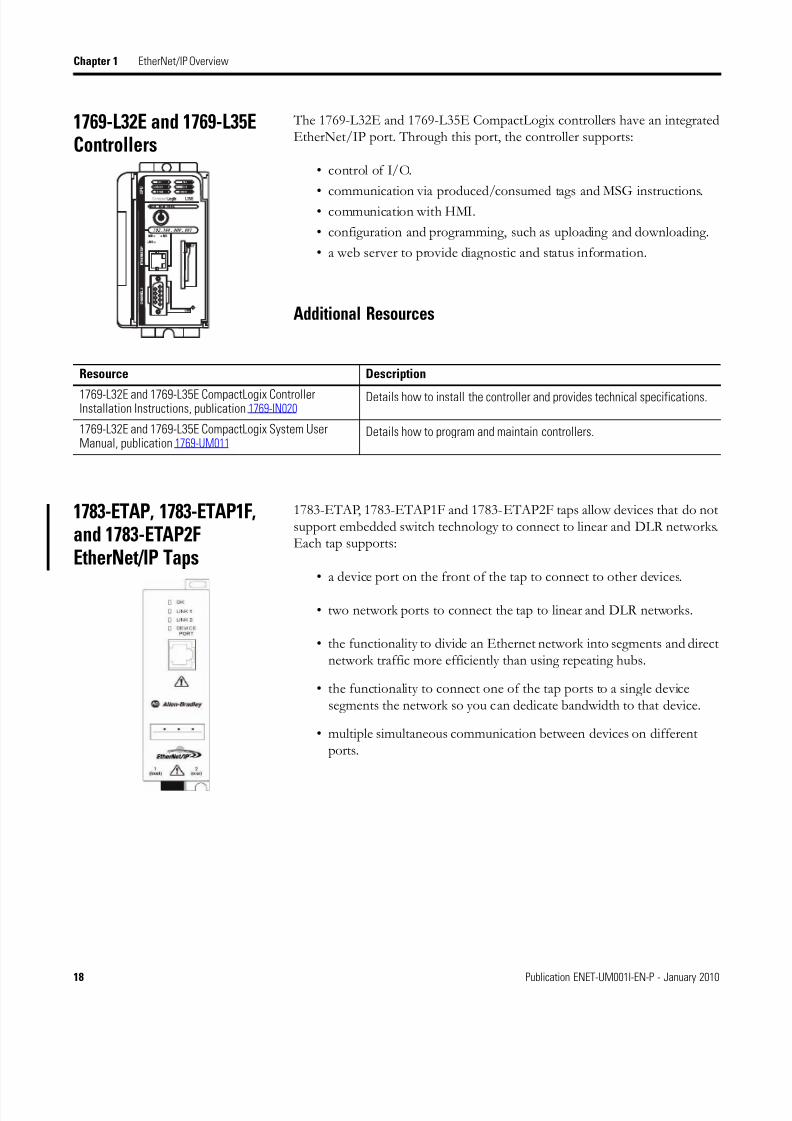
1769-L32E and 1769-L35EControllers
The 1769-L32E and 1769-L35E CompactLogix controllers have an integratedEtherNet/IP port. Through this port, the controller supports:
• control of I/O.
• communication via produced/consumed tags and MSG instructions.• communication with HMI.
• configuration and programming, such as uploading and downloading.
• a web server to provide diagnostic and status information.
Additional Resources
1783-ETAP, 1783-ETAP1F,and 1783-ETAP2FEtherNet/IP Taps
1783-ETAP, 1783-ETAP1F and 1783-ETAP2F taps allow devices that do notsupport embedded switch technology to connect to linear and DLR networks.Each tap supports:
• a device port on the front of the tap to connect to other devices.
• two network ports to connect the tap to linear and DLR networks.
• the functionality to divide an Ethernet network into segments and directnetwork traffic more efficiently than using repeating hubs.
• the functionality to connect one of the tap ports to a single devicesegments the network so you can dedicate bandwidth to that device.
• multiple simultaneous communication between devices on differentports.
Resource Description
1769-L32E and 1769-L35E CompactLogix ControllerInstallation Instructions, publication 1769-IN020
Details how to install the controller and provides technical specifications.
1769-L32E and 1769-L35E CompactLogix System UserManual, publication 1769-UM011
Details how to program and maintain controllers.
8/13/2019 EtherNet-IP Modules in Logix5000 Control Systems User Manual
http://slidepdf.com/reader/full/ethernet-ip-modules-in-logix5000-control-systems-user-manual 19/230
Publication ENET-UM001I-EN-P - January 2010 19
EtherNet/IP Overview Chapter 1
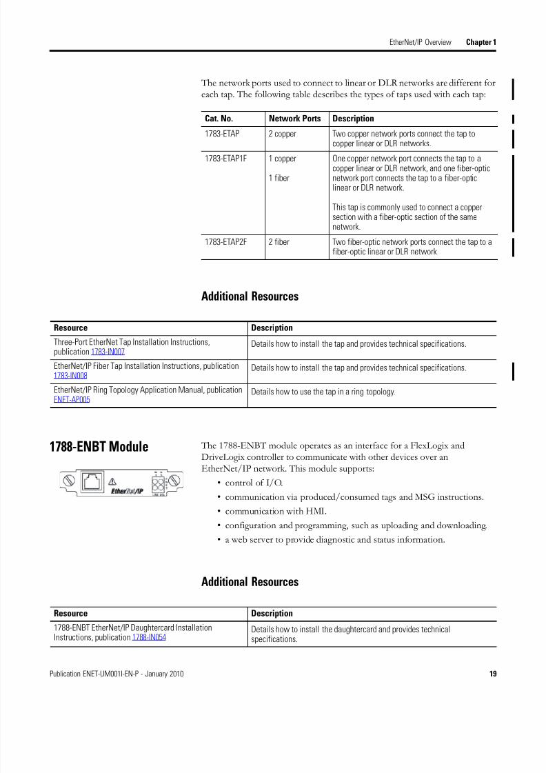
The network ports used to connect to linear or DLR networks are different foreach tap. The following table describes the types of taps used with each tap:
Additional Resources
1788-ENBT Module The 1788-ENBT module operates as an interface for a FlexLogix andDriveLogix controller to communicate with other devices over anEtherNet/IP network. This module supports:
• control of I/O.
• communication via produced/consumed tags and MSG instructions.
• communication with HMI.
• configuration and programming, such as uploading and downloading.
• a web server to provide diagnostic and status information.
Additional Resources
Cat. No. Network Ports Description
1783-ETAP 2 copper Two copper network ports connect the tap tocopper linear or DLR networks.
1783-ETAP1F 1 copper
1 fiber
One copper network port connects the tap to acopper linear or DLR network, and one fiber-opticnetwork port connects the tap to a fiber-opticlinear or DLR network.
This tap is commonly used to connect a coppersection with a fiber-optic section of the samenetwork.
1783-ETAP2F 2 fiber Two fiber-optic network ports connect the tap to afiber-optic linear or DLR network.
Resource Description
Three-Port EtherNet Tap Installation Instructions,publication 1783-IN007
Details how to install the tap and provides technical specifications.
EtherNet/IP Fiber Tap Installation Instructions, publication1783-IN008
Details how to install the tap and provides technical specifications.
EtherNet/IP Ring Topology Application Manual, publicationENET-AP005
Details how to use the tap in a ring topology.
Resource Description
1788-ENBT EtherNet/IP Daughtercard InstallationInstructions, publication 1788-IN054
Details how to install the daughtercard and provides technicalspecifications.

8/13/2019 EtherNet-IP Modules in Logix5000 Control Systems User Manual
http://slidepdf.com/reader/full/ethernet-ip-modules-in-logix5000-control-systems-user-manual 20/230
20 Publication ENET-UM001I-EN-P - January 2010
Chapter 1 EtherNet/IP Overview
1794-AENT Adapter The 1794-AENT adapter operates as an adapter for FLEX I/O modules onan EtherNet/IP network. This module supports:
• control of I/O.
• module configuration.• a web server to provide diagnostic and status information.
Additional Resources
1734-AENT and 1734-AENTRAdapters
The 1734-AENT and 1794-AENTR adapters operate as adapters for POINTI/O modules on an EtherNet/IP network. These adapters support:
• control of I/O.
• module configuration.
• linear and device level ring (DLR) topologies on the 1734-AENTRadapter only.
Additional Resources
Resource Description
1794-AENT FLEX I/O EtherNet/IP Adapter ModuleInstallation Instructions, publication 1794-IN082
Details how to install the adapter and provides technical specifications.
Resource Description
1734-AENT POINT I/O Ethernet Adapter InstallationInstructions, publication 1734-IN590
Details how to install the adapter and provides technical specifications.
1734-AENT POINT I/O Ethernet Adapter User Manual,publication 1734-UM011
Details how to configure and maintain an installed adapter.
8/13/2019 EtherNet-IP Modules in Logix5000 Control Systems User Manual
http://slidepdf.com/reader/full/ethernet-ip-modules-in-logix5000-control-systems-user-manual 21/230
Publication ENET-UM001I-EN-P - January 2010 21
EtherNet/IP Overview Chapter 1
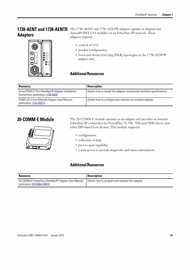
1738-AENT and 1738-AENTRAdapters
The 1738-AENT and 1738-AENTR adapters operate as adapters for ArmorPOINT I/O modules on an EtherNet/IP network. Theseadapters support:
• control of I/O.
• module configuration.
• linear and device level ring (DLR) topologies on the 1738-AENTRadapter only.
Additional Resources
20-COMM-E Module The 20-COMM-E module operates as an adapter and provides an internalEtherNet/IP connection for PowerFlex 70, 700, 700S and 700H drives, andother DPI-based host devices. This module supports:
• configuration.
• collection of data.• peer-to-peer capability.
• a web server to provide diagnostic and status information.
Additional Resources
1738-AENT
AdapterStatus
Network Activity
PointBusStatus
SystemPower
AdapterPower
EtherNet I/P
PWR
x1
x10
6
0
8 2
4
6
0
8 2
4
I
x100
6
0
8 2
4
Network Status
conformance tested™
P
A
E
D
D
R
S
S
Resource Description
ArmorPOINT 2-Port EtherNet/IP Adapter Installation
Instructions, publication 1738-IN028
Details how to install the adapters and provide technical specifications.
POINT I/O 2-Port Ethernet Adapter User Manual,publication 1734-UM014
Details how to configure and maintain an installed adapter.
Resource Description
20-COMM-E PowerFlex EtherNet/IP Adapter User Manual,publication 20COMM-UM010
Details how to program and maintain the adapter.

8/13/2019 EtherNet-IP Modules in Logix5000 Control Systems User Manual
http://slidepdf.com/reader/full/ethernet-ip-modules-in-logix5000-control-systems-user-manual 22/230
22 Publication ENET-UM001I-EN-P - January 2010
Chapter 1 EtherNet/IP Overview
22-COMM-E Module The 22-COMM-E module operates as an adapter and provides an internalEtherNet/IP connection for PowerFlex 40 AC drives. This module supports:
• user configuration of a module via a process display window.
• e-mail notification of faults.• monitoring of a diagnostics and event queue.
• direct launching of Drive Explorer or Drive Executive on a workstationto connect online over Ethernet.
• multi-drive support of up to five PowerFlex 4 and 40 AC drives toconnect to a single node on an EtherNet/IP network, ultimatelyreducing hardware costs.
Additional Resources
Resource Description
22-COMM-E PowerFlex EtherNet/IP Adapter User Manual,publication 22COMM-UM004
Details how to program and maintain the adapter.
8/13/2019 EtherNet-IP Modules in Logix5000 Control Systems User Manual
http://slidepdf.com/reader/full/ethernet-ip-modules-in-logix5000-control-systems-user-manual 23/230
Publication ENET-UM001I-EN-P - January 2010 23
EtherNet/IP Overview Chapter 1
EtherNet/IP CommunicationModules in a ControlSystem
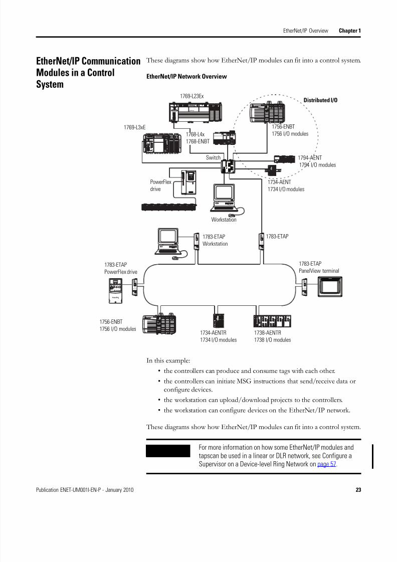
These diagrams show how EtherNet/IP modules can fit into a control system.
EtherNet/IP Network Overview
In this example:
• the controllers can produce and consume tags with each other.
• the controllers can initiate MSG instructions that send/receive data orconfigure devices.
• the workstation can upload/download projects to the controllers.
• the workstation can configure devices on the EtherNet/IP network.
These diagrams show how EtherNet/IP modules can fit into a control system.
Switch
Distributed I/O
1756-ENBT
1756 I/O modules
1794-AENT
1794 I/O modules
Workstation
1769-L3xE
1769-L23Ex
1734-AENT
1734 I/O modules
1768-L4x
1768-ENBT
PowerFlex
drive
1783-ETAP
PowerFlex drive
1783-ETAP
PanelView terminal
1783-ETAP
Workstation
1783-ETAP
1756-ENBT
1756 I/O modules1734-AENTR
1734 I/O modules
1738-AENTR
1738 I/O modules
IMPORTANT For more information on how some EtherNet/IP modules andtapscan be used in a linear or DLR network, see Configure aSupervisor on a Device-level Ring Network on page 57.
8/13/2019 EtherNet-IP Modules in Logix5000 Control Systems User Manual
http://slidepdf.com/reader/full/ethernet-ip-modules-in-logix5000-control-systems-user-manual 24/230
24 Publication ENET-UM001I-EN-P - January 2010
Chapter 1 EtherNet/IP Overview
Installing Communication Modules or Other Devices on theEtherNet/IP Network
In addition to using the installation instructions for each Rockwell AutomationEtherNet/IP device you install in your control system, you should also consultthe EtherNet/IP Media Planning and Installation Manual available fromODVA, the organization that supports network technologies built on theCommon Industrial Protocol (CIP).
You can obtain EtherNet/IP Media Planning and Installation Manual at theODVA website, that is, http://www.odva.org.
Safety I/O in EtherNet/IP
Control Systems
Rockwell Automation offers the Guard I/O product line that implements theEtherNet/IP safety protocol. This section provides an overview of themodules use in a safety system.
For more information on using Guard I/O modules, see Guard I/OEtherNet/IP Safety Modules user manual, publication 1791ES-UM001.
I/O Module Overview
The Guard I/O modules implement the CIP-safety protocol extensions overEtherNet/IP networks and provide various features for a safety system.
Use the modules to construct a safety-control network system that meets therequirements up to Safety Integrity Level 3 (SIL 3) as defined in IEC 61508,Functional Safety of Electrical, Electronic, and Programmable ElectronicSafety-related Systems, and the requirements for Safety Category 4 of the EN954-1 standard, Safety of machinery - Safety related parts of control systems.
Remote I/O communication for safety I/O data are performed through safetyconnections supporting CIP safety over an EtherNet/IP network, and dataprocessing is performed in the safety controller.
The status and fault diagnostics of the I/O modules are monitored by a safety
controller through a safety connection using a new or existing EtherNet/IPnetwork.
8/13/2019 EtherNet-IP Modules in Logix5000 Control Systems User Manual
http://slidepdf.com/reader/full/ethernet-ip-modules-in-logix5000-control-systems-user-manual 25/230
Publication ENET-UM001I-EN-P - January 2010 25
EtherNet/IP Overview Chapter 1
The following is a list of features common to Guard I/O modules:
• CIP-safety and EtherNet/IP protocol conformance
• Safety inputs
– Safety devices, such as emergency stop push buttons, gate switches,and safety light curtains, can be connected.
– Dual-channel mode evaluates consistency between two input signals(channels), which allows use of the module for Safety Category 3and 4.
– The time of a logical discrepancy between two channels can bemonitored using a discrepancy time setting.
– An external wiring short-circuit check is possible when inputs are wired in combination with test outputs.
– Independently adjustable on and off delay is available per channel.
• Test outputs
– Separate test outputs are provided for short circuit detection of asafety input (or inputs).
– Power (24V) can be supplied to devices, such as safety sensors.
– Test outputs can be configured as standard outputs.
– All Guard I/O modules have numerous test outputs, of which somecan be used for broken wire detection of a muting lamp.
• Safety outputs
– Dual-channel mode evaluates consistency between two output signals(channels).
– Safety outputs can be pulse tested to detect field wiring shorts to
24V DC and 0V DC.
• I/O status data - In addition to I/O data, the module includes statusdata for monitoring I/O circuits.
• Removable I/O connectors - I/O connectors support mechanicalkeying.
Guard I/O Catalog Numbers
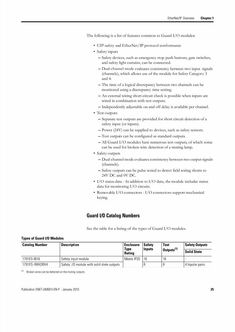
See the table for a listing of the types of Guard I/O modules.
Types of Guard I/O Modules
Catalog Number Description EnclosureTypeRating
SafetyInputs
Test
Outputs(1)Safety Outputs
Solid State
1791ES-IB16 Safety input module Meets IP20 16 16 -
1791ES-IB8XOBV4 Safety I/O module with solid state outputs 8 8 4 bipolar pairs
(1) Broken wires can be detected on the muting outputs.

8/13/2019 EtherNet-IP Modules in Logix5000 Control Systems User Manual
http://slidepdf.com/reader/full/ethernet-ip-modules-in-logix5000-control-systems-user-manual 26/230
26 Publication ENET-UM001I-EN-P - January 2010
Chapter 1 EtherNet/IP Overview
CIP Safety in EtherNet/IP Safety Architectures
Use Guard I/O modules in EtherNet/IP safety architectures as shown in thefigure. The Guard I/O family is a set of I/O modules that when connected to
an EtherNet/IP safety network are suitable for applications up to SIL3, asdefined in the IEC 61508 standard, and Safety Category 4, as defined in theEN 954-1 standard.
Safety Interlocking and Control via CIP Safety
Safety controllers control the safety outputs. Safety or standard controllers cancontrol the standard outputs.
For more information on using Guard I/O modules, see Guard I/O
EtherNet/IP Safety Modules user manual, publication 1791ES-UM001.
EtherNet/IP
ControlNet
DeviceNet
DeviceNet
Ethernet
RSLogix Software
RSView Software
ControlNet
DeviceNetDeviceNet
Standard Communication
Safety Communication

8/13/2019 EtherNet-IP Modules in Logix5000 Control Systems User Manual
http://slidepdf.com/reader/full/ethernet-ip-modules-in-logix5000-control-systems-user-manual 27/230
Publication ENET-UM001I-EN-P - January 2010 27
EtherNet/IP Overview Chapter 1
Bridge Across Networks Some EtherNet/IP modules support the ability to bridge or routecommunication through devices, depending on the capabilities of the platform
and communication devices.
You have a bridge when you have a connection between communicationdevices on two networks. For example, this bridge device has bothEtherNet/IP and DeviceNet connections, enabling Device 1 on theEtherNet/IP network to communicate with Device 2 on a DeviceNet networkthrough the bridge.
Bridge Device
Here, a workstation configures a drive on a DeviceNet network and bridgesEtherNet/IP networks to reach the drive.
IMPORTANT The update time of local I/O modules may increase whenbridging messages.
EtherNet/IP modules do not support the transfer of data to andfrom I/O modules across two or more segments of any network.
Bridge
EtherNet/IP
DeviceNet
Switch
Device 1
Device 2
CIP Message Bridging
CIP messages that originateon this network Can bridge to this network
EtherNet/IP ControlNet DeviceNet RS-232 Serial
EtherNet/IP Yes Yes Yes Yes
ControlNet Yes Yes Yes Yes
RS-232 Yes Yes Yes Yes
8/13/2019 EtherNet-IP Modules in Logix5000 Control Systems User Manual
http://slidepdf.com/reader/full/ethernet-ip-modules-in-logix5000-control-systems-user-manual 28/230
28 Publication ENET-UM001I-EN-P - January 2010
Chapter 1 EtherNet/IP Overview
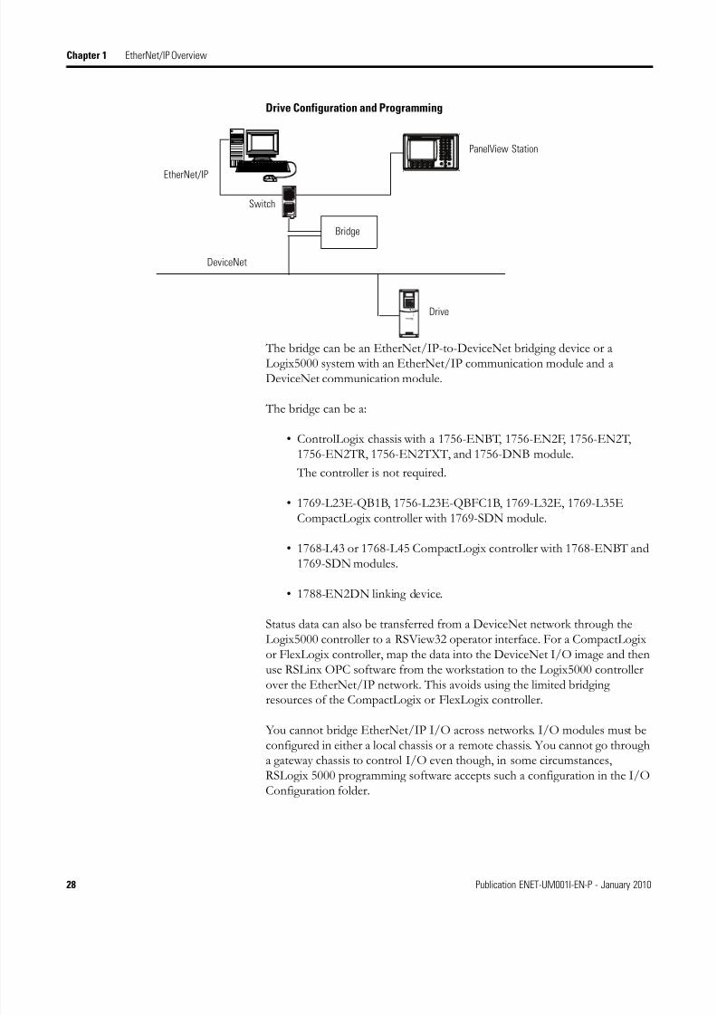
Drive Configuration and Programming
The bridge can be an EtherNet/IP-to-DeviceNet bridging device or aLogix5000 system with an EtherNet/IP communication module and aDeviceNet communication module.
The bridge can be a:
• ControlLogix chassis with a 1756-ENBT, 1756-EN2F, 1756-EN2T,1756-EN2TR, 1756-EN2TXT, and 1756-DNB module.
The controller is not required.
• 1769-L23E-QB1B, 1756-L23E-QBFC1B, 1769-L32E, 1769-L35ECompactLogix controller with 1769-SDN module.
• 1768-L43 or 1768-L45 CompactLogix controller with 1768-ENBT and1769-SDN modules.
• 1788-EN2DN linking device.
Status data can also be transferred from a DeviceNet network through theLogix5000 controller to a RSView32 operator interface. For a CompactLogixor FlexLogix controller, map the data into the DeviceNet I/O image and thenuse RSLinx OPC software from the workstation to the Logix5000 controllerover the EtherNet/IP network. This avoids using the limited bridgingresources of the CompactLogix or FlexLogix controller.
You cannot bridge EtherNet/IP I/O across networks. I/O modules must beconfigured in either a local chassis or a remote chassis. You cannot go througha gateway chassis to control I/O even though, in some circumstances,RSLogix 5000 programming software accepts such a configuration in the I/OConfiguration folder.
Bridge
EtherNet/IP
PanelView Station
DeviceNet
Drive
Switch
8/13/2019 EtherNet-IP Modules in Logix5000 Control Systems User Manual
http://slidepdf.com/reader/full/ethernet-ip-modules-in-logix5000-control-systems-user-manual 29/230
Publication ENET-UM001I-EN-P - January 2010 29
EtherNet/IP Overview Chapter 1
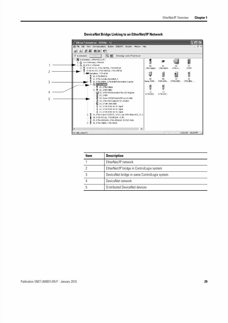
DeviceNet Bridge Linking to an EtherNet/IP Network
3
4
5
1
2
Item Description
1 EtherNet/IP network
2 EtherNet/IP bridge in ControlLogix system3 DeviceNet bridge in same ControlLogix system
4 DeviceNet network
5 Distributed DeviceNet devices

8/13/2019 EtherNet-IP Modules in Logix5000 Control Systems User Manual
http://slidepdf.com/reader/full/ethernet-ip-modules-in-logix5000-control-systems-user-manual 30/230
30 Publication ENET-UM001I-EN-P - January 2010
Chapter 1 EtherNet/IP Overview
EtherNet/IP NetworkSpecifications
These are the EtherNet/IP network connection specifications.
EtherNet/IP Network Specifications
CatalogNumber
Connections CIP UnconnectedMessages (backplane +Ethernet)
PacketRates (packets/
second)(1)
SNMPSupport(passwordrequired)
MediaSupport
TCP CIP I/O HMI/MSG Twisted Pair Fiber
1734-AENT,1734-AENTR
32 20 32 5000 900 No Yes No
1738-AENT,1738-AENTR
32 20 32 5000 900 No Yes No
1756-ENBT 64 128(2) 64 + 64 5000 900 Yes Yes No
1756-EN2F 128 256(2) 128 + 128 10,000 3200 Yes No Yes
1756-EN2T,1756-ENT2TR,1756-EN2TXT
128 256(2) 128 + 128 10,000 3200 Yes Yes No
1756-EWEB 64 128(2) 128 + 128 N/A 900 Yes Yes No
1768-ENBT(3) 32
64
64(2)
128
32 + 32 5000 960 Yes Yes No
1768-EWEB 64 128(2) 128 + 128 N/A 960 Yes Yes No
1769-L23Ex 8 32(2) 32 + 32 2000 380 Yes Yes No
1769-L3x E 6432
(2) 32 + 32 4000 760 Yes Yes No
1783-ETAP 64 N/A N/A N/A 900 No Yes No
1783-ETAP1F,1756-ETAP2F
64 N/A N/A N/A 900 No Yes Yes
1794-AENT 64 64 N/A 9500 N/A Yes Yes No
2x -COMM-E 30 16 16 400 50 No Yes No
(1) Total packet rate = I/O Produced Tag, max + HMI/MSG, max. Packet rates will vary depending on packet size. For more detailed specifications, see the EDS file for a
specific catalog number.
(2) CIP connections for these devices can be used for all explicit or all implicit applications.
Example: A 1756-ENBT has a total of 64 CIP connections and can be used for any combination of connections.
(3) The number of TCP and CIP connections supported by the 1768-ENBT module depends on the firmware revision you are using. If you are using firmware revision 1.x , themodule supports 32 TCP connections and 64 CIP connections. If you are using firmware revision 2.x or later, the module supports 64 TCP connections and 128 CIP
connections.
8/13/2019 EtherNet-IP Modules in Logix5000 Control Systems User Manual
http://slidepdf.com/reader/full/ethernet-ip-modules-in-logix5000-control-systems-user-manual 31/230
Publication ENET-UM001I-EN-P - January 2010 31
EtherNet/IP Overview Chapter 1
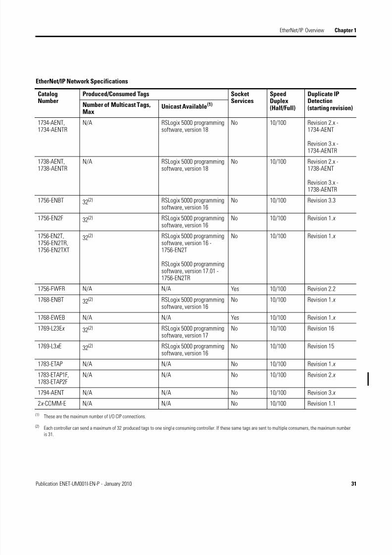
EtherNet/IP Network Specifications
CatalogNumber Produced/Consumed Tags SocketServices SpeedDuplex (Half/Full)
Duplicate IPDetection(starting revision)
Number of Multicast Tags,Max
Unicast Available(1)
1734-AENT,1734-AENTR
N/A RSLogix 5000 programmingsoftware, version 18
No 10/100 Revision 2.x -1734-AENT
Revision 3.x -1734-AENTR
1738-AENT,1738-AENTR
N/A RSLogix 5000 programmingsoftware, version 18
No 10/100 Revision 2.x -1738-AENT
Revision 3.x -1738-AENTR
1756-ENBT 32(2) RSLogix 5000 programmingsoftware, version 16
No 10/100 Revision 3.3
1756-EN2F 32(2) RSLogix 5000 programmingsoftware, version 16
No 10/100 Revision 1.x
1756-EN2T,1756-EN2TR,1756-EN2TXT
32(2) RSLogix 5000 programmingsoftware, version 16 -1756-EN2T
RSLogix 5000 programmingsoftware, version 17.01 -1756-EN2TR
No 10/100 Revision 1.x
1756-EWEB N/A N/A Yes 10/100 Revision 2.21768-ENBT 32(2) RSLogix 5000 programming
software, version 16No 10/100 Revision 1.x
1768-EWEB N/A N/A Yes 10/100 Revision 1.x
1769-L23Ex 32(2) RSLogix 5000 programmingsoftware, version 17
No 10/100 Revision 16
1769-L3x E 32(2) RSLogix 5000 programmingsoftware, version 16
No 10/100 Revision 15
1783-ETAP N/A N/A No 10/100 Revision 1.x
1783-ETAP1F,1783-ETAP2F
N/A N/A No 10/100 Revision 2.x
1794-AENT N/A N/A No 10/100 Revision 3.x
2x -COMM-E N/A N/A No 10/100 Revision 1.1
(1) These are the maximum number of I/O CIP connections.
(2) Each controller can send a maximum of 32 produced tags to one single consuming controller. If these same tags are sent to multiple consumers, the maximum number
is 31.

8/13/2019 EtherNet-IP Modules in Logix5000 Control Systems User Manual
http://slidepdf.com/reader/full/ethernet-ip-modules-in-logix5000-control-systems-user-manual 32/230
32 Publication ENET-UM001I-EN-P - January 2010
Chapter 1 EtherNet/IP Overview
IMPORTANT Non-CIP communication requires 1756-EWEB, 1768-EWEB orMicroLogix 1400 embedded web server sockets.
For more information on the 1756-EWEB or 1768-EWEBmodules, see the EtherNet/IP Web Server User Manual,publication ENET-UM527.
For more information on the enhanced MicroLogix 1400controllers, see the MicroLogix 1400 Embedded Web ServerUser Manual, publication 1766-UM002

8/13/2019 EtherNet-IP Modules in Logix5000 Control Systems User Manual
http://slidepdf.com/reader/full/ethernet-ip-modules-in-logix5000-control-systems-user-manual 33/230
33Publication ENET-UM001I-EN-P - January 2010 33
Chapter 2
Configure a Workstation to Operate on anEtherNet/IP Network
Introduction This chapter describes how to configure a workstation to operate on anEtherNet/IP network.
You need to load an Ethernet communication driver for all Rockwell Softwareapplications to communicate with devices on an EtherNet/IP network. A workstation needs this driver to:
• upload and download controller projects over the EtherNet/IP network
via RSLogix 5000 programming software.
• configure EtherNet/IP network parameters for devices on the network via RSNetWorx for EtherNet/IP software.
• collect controller data for PanelView terminals and RSView applications.
You can choose from any of three Ethernet drives:
• AB_ETHIP
• AB_ETH
• TCP
We recommend that you use the AB_ETHIP driver.
Before loading a communication driver, make sure:
• the Ethernet communication card is already installed in the workstation.
• the IP address and other network parameters are correctly configuredfor the workstation.
• the workstation is properly connected to the EtherNet/IP network.
See the documentation for the appropriate Ethernet communication modulefor information on installing and configuring the module.

8/13/2019 EtherNet-IP Modules in Logix5000 Control Systems User Manual
http://slidepdf.com/reader/full/ethernet-ip-modules-in-logix5000-control-systems-user-manual 34/230
34 Publication ENET-UM001I-EN-P - January 2010
Chapter 2 Configure a Workstation to Operate on an EtherNet/IP Network
Configure the EthernetCommunication Driver inRSLinx Software
To configure the Ethernet communication driver, perform this procedure.
1. In RSLinx software, from the Communications pull-down menu,choose Configure Drivers.
The Configure Drivers dialog box appears.
2. From Available Driver Types pull-down menu, choose EtherNet/IPDriver or Ethernet devices and click Add New.
The Add New RSLinx Driver dialog box appears.
3. Type a name for the new driver and click OK.

8/13/2019 EtherNet-IP Modules in Logix5000 Control Systems User Manual
http://slidepdf.com/reader/full/ethernet-ip-modules-in-logix5000-control-systems-user-manual 35/230
Publication ENET-UM001I-EN-P - January 2010 35
Configure a Workstation to Operate on an EtherNet/IP Network Chapter 2
The Configure driver dialog box appears.
4. Select Browse Local Subnet.
5. Click Apply.
6. Click OK.
This new driver is now available.

8/13/2019 EtherNet-IP Modules in Logix5000 Control Systems User Manual
http://slidepdf.com/reader/full/ethernet-ip-modules-in-logix5000-control-systems-user-manual 36/230
36 Publication ENET-UM001I-EN-P - January 2010
Chapter 2 Configure a Workstation to Operate on an EtherNet/IP Network
Notes:

8/13/2019 EtherNet-IP Modules in Logix5000 Control Systems User Manual
http://slidepdf.com/reader/full/ethernet-ip-modules-in-logix5000-control-systems-user-manual 37/230
37Publication ENET-UM001I-EN-P - January 2010 37
Chapter 3
Configure Stratix Switches
Introduction This chapter describes how you can use a Stratix switch.
Stratix switches provide a rugged, easy-to-use, secure switching infrastructurefor harsh environments. You can connect these switches to network devicessuch as servers, routers, and other switches. In industrial environments, youcan connect any Ethernet-enabled industrial communication devices includingprogrammable log controllers (PLC’s), human-machine interfaces (HMI’s),drives, sensors, and I/O.
Select a Switch Select the switch depending on the application and environment.
Topic Page
Set Up the Hardware 38
Select a Switch 37
Switch Features 38
Additional Resources 39
If your application Select
• Integrates enterprise and manufacturingenvironments
• Requires I/O and Produced/Consumedcommunication
• Requires diagnostics data
• Requires security options
Stratix 8000 modular, managed switch
• Integrates plant floor devices
• Requires I/O and Produced/Consumedcommunication
• Require diagnostics data
• Requires security options
Stratix 6000 fixed, managed switch
• Requires easy set-up and directrelacement of switches
• Meets IP20 or IP67 standards
Stratix 2000 unmanaged switch

8/13/2019 EtherNet-IP Modules in Logix5000 Control Systems User Manual
http://slidepdf.com/reader/full/ethernet-ip-modules-in-logix5000-control-systems-user-manual 38/230
38 Publication ENET-UM001I-EN-P - January 2010
Chapter 3 Configure Stratix Switches
Set Up the Hardware In this example, multiple Ethernet-enabled devices are connected via a Stratixswitch.
EtherNet/IP-enabled Devices Connected Via a Stratix Switch
Switch Features The features available vary according to the switch you select.
1
3
4
2 5
Device Description
1 HMI device
2 Drive
3 Stratix switch
4 Logix chassis
5 Distributed I/O
Stratix Features
Switch Configuration Features Monitoring Features Security Features Maintenance Features
Stratix 8000 • IT-friendly configurationtool – Cisco CommandLine Interface, CiscoNetwork Assistant,Device Manager
• Express setup – quickstart-up feature
• “Smartport” – easyswitch port optimizationfeature
• Web enabledconfiguration usingembedded web pages
• AOP configurationstored as part of projectin RSLogix 5000
• RSLogix 5000pre-defined tags alloweasy access for HMIdevelopment
• Sample face platesavailable for Viewapplications
• Supports all securityfeatures available in theCisco Catalyst line ofswitches including:
- 802.1x industrystandardauthentication
- MAC ID deviceauthentication
- ACL (Access ControlList)
- Port control
• RemovableCompactFlash cardholds OS andconfiguration of theswitch which can beeasily transferred to anew one
• Standard DHCP Option82 support enablesfixed IP addressassignment to switchports

8/13/2019 EtherNet-IP Modules in Logix5000 Control Systems User Manual
http://slidepdf.com/reader/full/ethernet-ip-modules-in-logix5000-control-systems-user-manual 39/230
Publication ENET-UM001I-EN-P - January 2010 39
Configure Stratix Switches Chapter 3
Additional Resources These documents contain additional information concerning related Rockwell Automation products.
Stratix 6000 • Default IP addressallows quick start up
• Web enabledconfiguration usingembedded web pages
• AOP configurationstored as part of projectin RSLogix 5000
• Real-time diagnosticsavailable in embedded
web pages• RSLogix 5000
pre-defined tags alloweasy access for HMIdevelopment
- Traffic level monitorw/ alarms
• Sample face platesavailable for Viewapplications
• Supports all securityfeatures available in the
Cisco Catalyst line ofswitches including:
- Port control
- MAC ID deviceauthentication
- Switch accessusername/passwordauthentication
• Parameter settings heldin Logix project and are
automaticallydownloaded afterswitch replacement (IPaddress must be setprior to download)
• DHCP per port ensuresconnected devices areassigned the rightaddresses afterreplacement
Stratix 2000 No parameters to configurefor unmanaged switches
No diagnostics areavailable in unmanaged
switches
No security featuresavailable in unmanaged
switches
Direct replacement - noset-up or configuration
required
Stratix Features
Switch Configuration Features Monitoring Features Security Features Maintenance Features
Resource Description
Stratix 8000 and 8300 EthernetManaged Switches InstallationInstructions, publication1783-IN005
Describes how to install and configure the switch.
Stratix 6000 Ethernet ManagedSwitches InstallationInstructions, publication1783-IN004
Describes how to install and configure the switch.
Stratix 2000 EthernetUnmanaged Switch InstallationInstructions, publication1783-IN001
Describes how to install and configure the switch.
Stratix 8000 Ethernet ManagedSwitches Hardware UserManual, publication1783-UM002
Provides detailed information on installing and usingyour switches.
Stratix 8000 and 8300 EthernetManaged Switches Sofwareuser Manual, publication1783-UM003
Provides detailed information on configuring andmanaging your switches.
Stratix 6000 Ethernet ManagedSwitch User Manual,publication 1783-UM001
Provides detailed information on configuring andmanaging your switches.
Device Manager online help(provided with the switch)
Provides context-sensitive information on configuringand using the switch, including system messages.

8/13/2019 EtherNet-IP Modules in Logix5000 Control Systems User Manual
http://slidepdf.com/reader/full/ethernet-ip-modules-in-logix5000-control-systems-user-manual 40/230
40 Publication ENET-UM001I-EN-P - January 2010
Chapter 3 Configure Stratix Switches
Notes:
8/13/2019 EtherNet-IP Modules in Logix5000 Control Systems User Manual
http://slidepdf.com/reader/full/ethernet-ip-modules-in-logix5000-control-systems-user-manual 41/230
41Publication ENET-UM001I-EN-P - January 2010 41
Chapter 4
Configure an EtherNet/IP Module to Operateon the Network
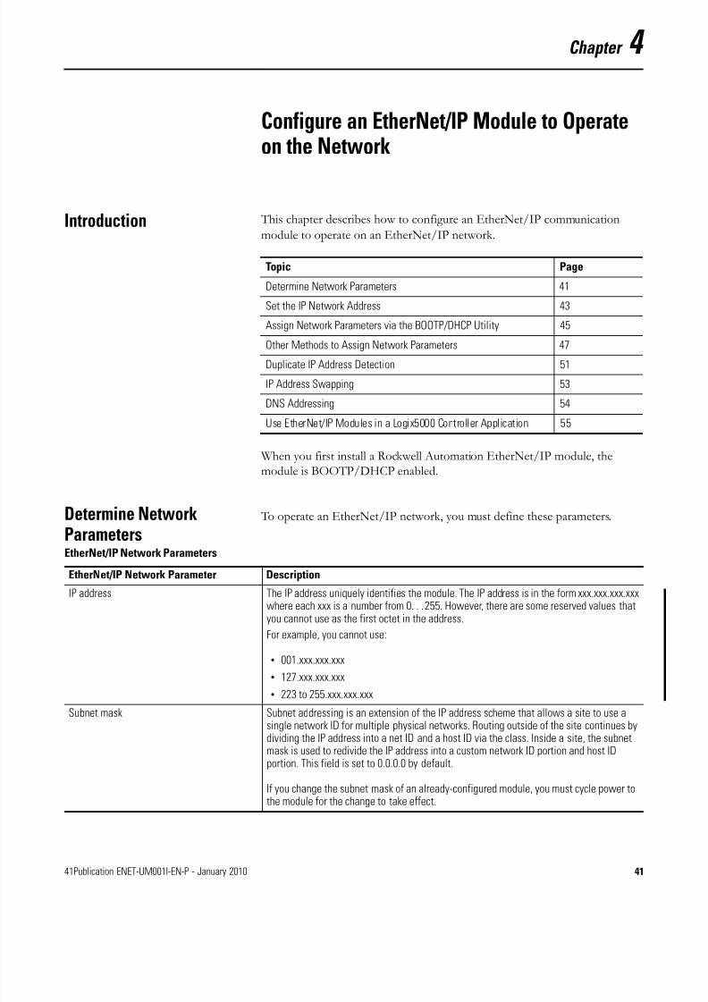
Introduction This chapter describes how to configure an EtherNet/IP communication
module to operate on an EtherNet/IP network.
When you first install a Rockwell Automation EtherNet/IP module, themodule is BOOTP/DHCP enabled.
Determine NetworkParameters
To operate an EtherNet/IP network, you must define these parameters.
Topic Page
Determine Network Parameters 41
Set the IP Network Address 43
Assign Network Parameters via the BOOTP/DHCP Utility 45
Other Methods to Assign Network Parameters 47
Duplicate IP Address Detection 51
IP Address Swapping 53
DNS Addressing 54
Use EtherNet/IP Modules in a Logix5000 Controller Application 55
EtherNet/IP Network Parameters
EtherNet/IP Network Parameter Description
IP address The IP address uniquely identifies the module. The IP address is in the form xxx.xxx.xxx.xxxwhere each xxx is a number from 0. . .255. However, there are some reserved values thatyou cannot use as the first octet in the address.
For example, you cannot use:
• 001.xxx.xxx.xxx
• 127.xxx.xxx.xxx
• 223 to 255.xxx.xxx.xxx
Subnet mask Subnet addressing is an extension of the IP address scheme that allows a site to use asingle network ID for multiple physical networks. Routing outside of the site continues bydividing the IP address into a net ID and a host ID via the class. Inside a site, the subnetmask is used to redivide the IP address into a custom network ID portion and host IDportion. This field is set to 0.0.0.0 by default.
If you change the subnet mask of an already-configured module, you must cycle power tothe module for the change to take effect.

8/13/2019 EtherNet-IP Modules in Logix5000 Control Systems User Manual
http://slidepdf.com/reader/full/ethernet-ip-modules-in-logix5000-control-systems-user-manual 42/230
42 Publication ENET-UM001I-EN-P - January 2010
Chapter 4 Configure an EtherNet/IP Module to Operate on the Network
If you use DNS addressing, or reference the module via host name in MSGinstructions, define these parameters.
Check with your Ethernet network administrator to determine if you need to
specify these parameters.
Gateway A gateway connects individual physical networks into a system of networks. When a nodeneeds to communicate with a node on another network, a gateway transfers the data
between the two networks. This field is set to 0.0.0.0 by default.
EtherNet/IP Network Parameters
EtherNet/IP Network Parameter Description
EtherNet/IP Network Parameters for DNS Addressing
EtherNet/IP Network Parameter Description
Host name A host name is part of a text address that identifies the host for a module. The full textaddress of a module is host_name .domain_name .
Domain name A domain name is part of a text address that identifies the domain in which the moduleresides. The full text address of a module is host_name .domain_name . The domain name
has a 48-character limit.
If you specify a DNS server, you must enter a domain name. Also, if you send email fromthe module, some mail relay servers require a domain name during the initial handshakeof the SMTP session.
Primary DNS server address This identifies any DNS servers used in the network. You must have a DNS serverconfigured if you specified a domain name or a host name in the module’s configuration.The DNS server converts the domain name or host name to an IP address that can be usedby the network.
For more information on DNS addressing, see page 54.
Secondary DNS server address

8/13/2019 EtherNet-IP Modules in Logix5000 Control Systems User Manual
http://slidepdf.com/reader/full/ethernet-ip-modules-in-logix5000-control-systems-user-manual 43/230
Publication ENET-UM001I-EN-P - January 2010 43
Configure an EtherNet/IP Module to Operate on the Network Chapter 4
Set the IP Network Address EtherNet/IP modules ship with the IP address configuration switches set to999 and DHCP enabled. You can set the network Internet Protocol (IP)address by:
• using the switches available on some modules.
• using a Bootstrap Protocol (BOOTP)/Dynamic Host ConfigurationProtocol (DHCP) server, such as the Rockwell AutomationBOOTP-DHCP server utility.
• using RSLinx software or RSLogix 5000 programming software.
IMPORTANT The switches on 1783-ETAP, 1783-ETAP1F and1783-ETAP2F taps are used somewhat differently thanother EtherNet/IP modules.
For more information on how to use switches on thetaps, see either of the following:
• EtherNet/IP Tap Installation Instructions, pubication1783-IN007
• EtherNet/IP Fiber Tap Installation Instructions,
publication 1783-IN008
IMPORTANT The adapter reads the configuration switches only whenyou cycle power to determine if the switches are set to avalid number.
Valid settings range from 001...255, with someexceptions. There are some reserved values that youcannot use as the first octet in the address.
For example, you cannot use:
• 001.xxx.xxx.xxx
• 127.xxx.xxx.xxx
• 223 to 255.xxx.xxx.xxx
To restore the factory default settings on the module, set
the switches to 888.
8/13/2019 EtherNet-IP Modules in Logix5000 Control Systems User Manual
http://slidepdf.com/reader/full/ethernet-ip-modules-in-logix5000-control-systems-user-manual 44/230
44 Publication ENET-UM001I-EN-P - January 2010
Chapter 4 Configure an EtherNet/IP Module to Operate on the Network
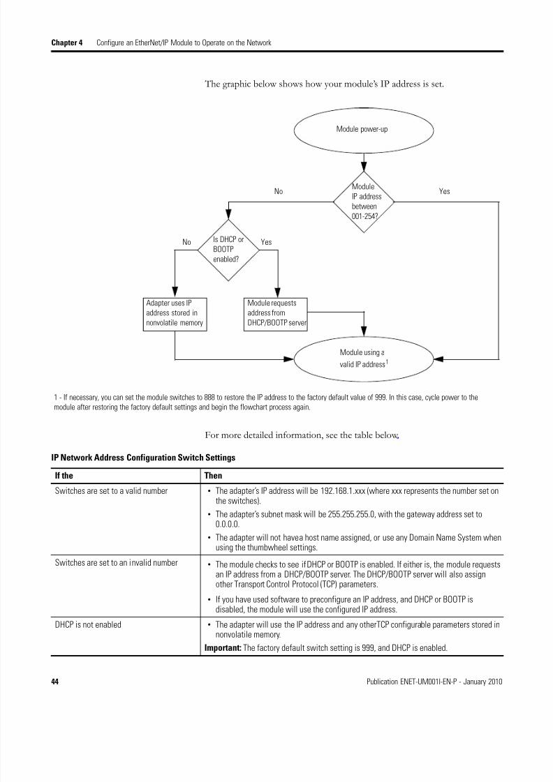
The graphic below shows how your module’s IP address is set.
For more detailed information, see the table below .
Module power-up
Module using a
valid IP address1
Module
IP address
between
001-254?
YesNo
Is DHCP or
BOOTP
enabled?
YesNo
Module requests
address from
DHCP/BOOTP server
Adapter uses IP
address stored in
nonvolatile memory
1 - If necessary, you can set the module switches to 888 to restore the IP address to the factory default value of 999. In this case, cycle power to the
module after restoring the factory default settings and begin the flowchart process again.
IP Network Address Configuration Switch Settings
If the Then
Switches are set to a valid number • The adapter’s IP address will be 192.168.1.xxx (where xxx represents the number set onthe switches).
• The adapter’s subnet mask will be 255.255.255.0, with the gateway address set to0.0.0.0.
• The adapter will not have a host name assigned, or use any Domain Name System when
using the thumbwheel settings.
Switches are set to an invalid number • The module checks to see if DHCP or BOOTP is enabled. If either is, the module requestsan IP address from a DHCP/BOOTP server. The DHCP/BOOTP server will also assignother Transport Control Protocol (TCP) parameters.
• If you have used software to preconfigure an IP address, and DHCP or BOOTP isdisabled, the module will use the configured IP address.
DHCP is not enabled • The adapter will use the IP address and any otherTCP configurable parameters stored innonvolatile memory.
Important: The factory default switch setting is 999, and DHCP is enabled.
8/13/2019 EtherNet-IP Modules in Logix5000 Control Systems User Manual
http://slidepdf.com/reader/full/ethernet-ip-modules-in-logix5000-control-systems-user-manual 45/230
Publication ENET-UM001I-EN-P - January 2010 45
Configure an EtherNet/IP Module to Operate on the Network Chapter 4
Assign NetworkParameters via theBOOTP/DHCP Utility
By default, the EtherNet/IP module is BOOTP enabled. TheBOOTP/DHCP utility is a standalone program that is located in the:
• BOOTP-DHCP Server folder accessed from the Start menu.
• Tools directory on the RSLogix 5000 installation CD.
This utility recognizes BOOTP-enabled devices and provides an interface toconfigure a static IP address for each device.
To assign network parameters via the BOOTP/DHCP utility, perform this
procedure.
1. Start the BOOTP/DHCP software.
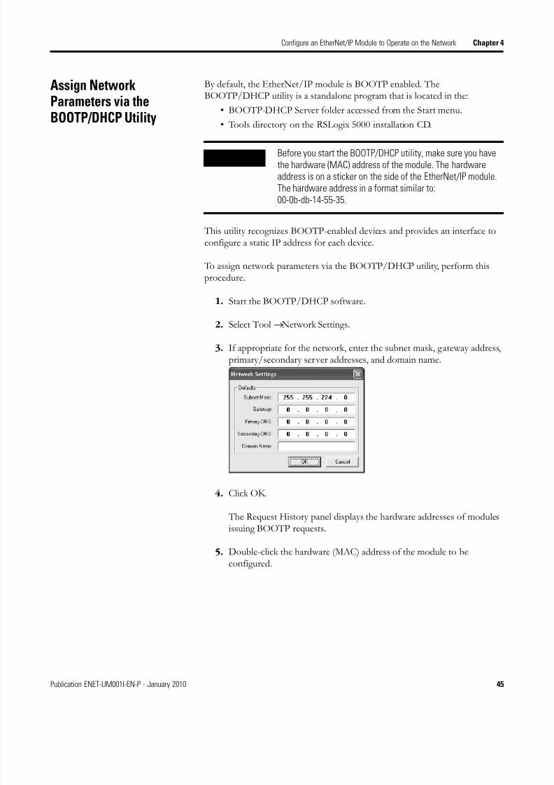
2. Select Tool →Network Settings.
3. If appropriate for the network, enter the subnet mask, gateway address,primary/secondary server addresses, and domain name.
4. Click OK.
The Request History panel displays the hardware addresses of modulesissuing BOOTP requests.
5. Double-click the hardware (MAC) address of the module to beconfigured.
IMPORTANT Before you start the BOOTP/DHCP utility, make sure you havethe hardware (MAC) address of the module. The hardwareaddress is on a sticker on the side of the EtherNet/IP module.The hardware address in a format similar to:00-0b-db-14-55-35.
8/13/2019 EtherNet-IP Modules in Logix5000 Control Systems User Manual
http://slidepdf.com/reader/full/ethernet-ip-modules-in-logix5000-control-systems-user-manual 46/230
46 Publication ENET-UM001I-EN-P - January 2010
Chapter 4 Configure an EtherNet/IP Module to Operate on the Network
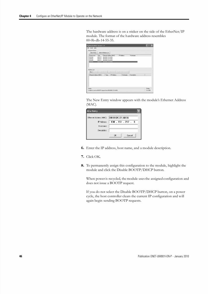
The hardware address is on a sticker on the side of the EtherNet/IPmodule. The format of the hardware address resembles00-0b-db-14-55-35.
The New Entry window appears with the module’s Ethernet Address
(MAC).
6. Enter the IP address, host name, and a module description.
7. Click OK.
8. To permanently assign this configuration to the module, highlight themodule and click the Disable BOOTP/DHCP button.
When power is recycled, the module uses the assigned configuration anddoes not issue a BOOTP request.
If you do not select the Disable BOOTP/DHCP button, on a powercycle, the host controller clears the current IP configuration and willagain begin sending BOOTP requests.

8/13/2019 EtherNet-IP Modules in Logix5000 Control Systems User Manual
http://slidepdf.com/reader/full/ethernet-ip-modules-in-logix5000-control-systems-user-manual 47/230
Publication ENET-UM001I-EN-P - January 2010 47
Configure an EtherNet/IP Module to Operate on the Network Chapter 4
Other Methods to AssignNetwork Parameters
There are other methods to assign network parameters.
These factors might affect your choice of method:
• Network isolation from or integration into the plant/enterprise network
• Network size
For large networks, even isolated networks, it might be more convenientand safer to use a BOOTP/DHCP server rather than RSLogix 5000 orRSLinx software. The BOOTP/DHCP server also limits the possibilityof assigning duplicate IP addresses.
• Company policies and procedures dealing with plant floor networkinstallation and maintenance
• Level of involvement by IT personnel in plant floor network installationand maintenance
• Type of training offered to control engineers and maintenancepersonnel
If you use the Rockwell Automation BOOTP or DHCP server in an uplinkedsubnet where an enterprise DHCP server exists, a module may get an addressfrom the enterprise server before the Rockwell Automation utility even seesthe module. You might have to disconnect from the uplink to set the addressand configure the module to retain its static address before reconnecting to theuplink. This is not a problem if you have node names configured in the moduleand leave DHCP enabled.
Assignment of Network Parameters
If Use this method for assigning network parameter Page
• A BOOTP server is not available
• The EtherNet/IP module is connected to anotherNetLinx network
RSLinx software 48
The RSLogix 5000 project is online with the controller thatcommunicates to or through the EtherNet/IP module
RSLogix 5000 programming software 50
DHCP is enabled (not BOOTP) for the EtherNet/IP module DHCP software 51
You need to cycle power to your device for some reason Thumbwheel switches 43
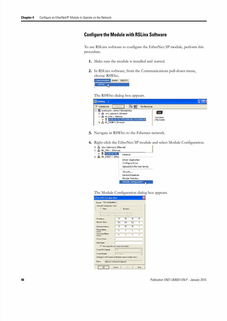
8/13/2019 EtherNet-IP Modules in Logix5000 Control Systems User Manual
http://slidepdf.com/reader/full/ethernet-ip-modules-in-logix5000-control-systems-user-manual 48/230
48 Publication ENET-UM001I-EN-P - January 2010
Chapter 4 Configure an EtherNet/IP Module to Operate on the Network
Configure the Module with RSLinx Software
To use RSLinx software to configure the EtherNet/IP module, perform thisprocedure.
1. Make sure the module is installed and started.
2. In RSLinx software, from the Communications pull-down menu,choose RSWho.
The RSWho dialog box appears.
3. Navigate in RSWho to the Ethernet netw ork.
4. Right-click the EtherNet/IP module and select Module Configuration.
The Module Configuration dialog box appears.

8/13/2019 EtherNet-IP Modules in Logix5000 Control Systems User Manual
http://slidepdf.com/reader/full/ethernet-ip-modules-in-logix5000-control-systems-user-manual 49/230
Publication ENET-UM001I-EN-P - January 2010 49
Configure an EtherNet/IP Module to Operate on the Network Chapter 4
5. Click the Port Configuration tab.
6. For Network Configuration Type, select Static to permanently assignthis configuration to the port.
a. In the IP Address field, type the IP address.
b. In the Network Mask field, type the network mask address.
c. In the Gateway Address field, type the gateway address.
d. In the Primary Name Server field, type the name of the primaryserver.
e. In the Secondary Name Server field, type the name of the secondaryserver.
f. In the Domain Name field, type the domain name.
g. In the Host Name field, type the host name.
7. Configure the port settings.
8. Click OK.
IMPORTANT If you select Dynamic, on a power cycle, the controllerclears the current IP configuration and resumes sendingBOOTP requests.
To Then
Use the default port speedand duplex settings
Leave checked the Auto-negotiate port speed andduplex check box.
Important: The default port speed is 100, and thedefault duplex setting is Full.
Manually configure yourport’s speed and duplexsettings.
a.Uncheck the Auto-negotiate port speed andduplex check box.
b. From the Current Port Speed pull-down menu,select a port speed.
c. From the Current Duplex pull-down menu,choose Half Duplex.
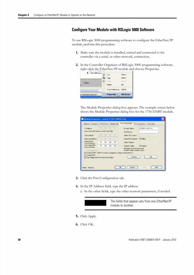
8/13/2019 EtherNet-IP Modules in Logix5000 Control Systems User Manual
http://slidepdf.com/reader/full/ethernet-ip-modules-in-logix5000-control-systems-user-manual 50/230
50 Publication ENET-UM001I-EN-P - January 2010
Chapter 4 Configure an EtherNet/IP Module to Operate on the Network
Configure Your Module with RSLogix 5000 Software
To use RSLogix 5000 programming software to configure the EtherNet/IPmodule, perform this procedure.
1. Make sure the module is installed, started and connected to thecontroller via a serial, or other network, connection.
2. In the Controller Organizer of RSLogix 5000 programming software,right-click the EtherNet/IP module and choose Properties.
The Module Properties dialog box appears. The example screen belowshows the Module Properties dialog box for the 1756-ENBT module.
3. Click the Port Configuration tab.
4. In the IP Address field, type the IP address.
a. In the other fields, type the other network parameters, if needed.
5. Click Apply.
6. Click OK.
IMPORTANT The fields that appear vary from one EtherNet/IPmodule to another.

8/13/2019 EtherNet-IP Modules in Logix5000 Control Systems User Manual
http://slidepdf.com/reader/full/ethernet-ip-modules-in-logix5000-control-systems-user-manual 51/230
Publication ENET-UM001I-EN-P - January 2010 51
Configure an EtherNet/IP Module to Operate on the Network Chapter 4
Use DHCP Software to Set the IP Address
Dynamic Host Configuration Protocol (DHCP) software automatically assignsIP addresses to client stations logging onto a TCP/IP network. DHCP is
based on BOOTP and maintains some backward compatibility. The maindifference is that BOOTP allows for manual configuration (static), whileDHCP allows for both static and dynamic allocation of network addresses andconfigurations to newly attached modules.
Be cautious when using DHCP software to configure a module. A BOOTPclient, such as the EtherNet/IP modules, can boot from a DHCP server onlyif the DHCP server is specifically written to also handle BOOTP queries. Thisis specific to the DHCP software package used. Consult your systemadministrator to see if a DHCP package supports BOOTP commands andmanual IP allocation.
Duplicate IP AddressDetection
Some EtherNet/IP modules (and their future revisions) support duplicate IPaddress detection.
ATTENTION The EtherNet/IP module must be assigned a fixed networkaddress. The IP address of this module must not be dynamicallyprovided.
Failure to observe this precaution may result in unintendedmachine motion or loss of process control.
Cat. No. Firmware Revision
1734-AENT, 1734-AENTR 2.1 and later
1738-AENT, 1738-AENTR 3.002 and later
1756-ENBT 3.2 and later
1756-EN2F 1.x and later
1756-EN2T 1.x and later
1756-EN2TR 1.x and later
1756-EN2TRXT 1.x and later
1768-ENBT 1.x and later
1769-L2x 17.01 and later
1769-L32E and 1769-L35E 15.01 and later
1783-ETAP 1.x and later
1783-ETAP1F, 1783-ETAP2F 2.x and later

8/13/2019 EtherNet-IP Modules in Logix5000 Control Systems User Manual
http://slidepdf.com/reader/full/ethernet-ip-modules-in-logix5000-control-systems-user-manual 52/230
52 Publication ENET-UM001I-EN-P - January 2010
Chapter 4 Configure an EtherNet/IP Module to Operate on the Network
When you change the IP address or connect one of these modules to anEtherNet/IP network, the module checks to make sure that the IP addressassigned to this module does not match the address of any other networkdevice. If the module determines that another device on the network with amatching IP address, the EtherNet/IP port of the module goes into conflictmode, where the module’s:
• OK status indicator blinks red.
• Network (NET) status indicator is solid red.• front display indicates the conflict (1756-ENBT, 1756-EN2F,
1756-EN2T, 1756-EN2TR, and 1756-EN2TXT).
The display scrolls:OK <IP_address_of_this_module> Duplicate IP<Mac_address_of_duplicate_node_detected>
For example: OK 10.88.60.196 Duplicate IP - 00:00:BC:02:34:B4
To resolve this conflict, use the instructions in this chapter to change the IPaddress of the module. Then cycle power to the module or reset the modules,such as disconnecting and then reconnecting the EtherNet/IP cable cable.
Two modules could possibly detect a conflict simultaneously. If this occurs,perform this procedure.
1. Remove the module with the incorrect IP address or correct its conflict.
2. Cycle power to the second module or disconnect its EtherNet/IP cable
3. Reconnect the cable.
1788-ENBT 2.1 and later
1794-AENT Series A - 3.x and later
Series B - 4.1 and later
2x-COMM-E 1.1 and later
Cat. No. Firmware Revision

8/13/2019 EtherNet-IP Modules in Logix5000 Control Systems User Manual
http://slidepdf.com/reader/full/ethernet-ip-modules-in-logix5000-control-systems-user-manual 53/230
Publication ENET-UM001I-EN-P - January 2010 53
Configure an EtherNet/IP Module to Operate on the Network Chapter 4
Detection of Duplicate IP Addresses
Devices in conflict over an IP address behave differently depending on whether connections have been established to either of the modules and
whether both modules support duplicate IP address detection.
IP Address Swapping This EtherNet/IP modules supports IP address swapping in ControlLogixredundancy systems:
• 1756-ENBT, firmware revision 3.1 and later
• 1756-EN2T, firmware revision 2.003 and later
• 1756-EN2TR, firmware revision 2.x and later
• 1756-EN2TXT, firmware revision 2.1 and later
During a switchover in ControlLogix redundancy systems, these module swapsits IP address with its partner modules in the other redundant chassis.
For more information about IP address swapping, see the ControlLogixRedundancy User Manual, publication 1756-UM523. When using publication1756-UM23, be aware that neither the 1756-EN2TR module nor the1756-EN2TXT module supports redundancy.
Device Conflict Over Duplicate IP Addresses
If Then
Both modules support duplicate IP addressdetection
The first started module uses and retains its IP address.
The other module will detect a conflict, give up the IP address and enter conflict mode.
Both modules support duplicate IP addressdetection and are started at roughly the sametime
They surrender the IP address and enter conflict mode
One module supports duplicate IP address
detection and a second module does not
The second module generally keeps its IP address, regardless of which module first
obtains the IP address.
The module that supports duplicate IP address detection will detect the conflict andgive up the IP address.
8/13/2019 EtherNet-IP Modules in Logix5000 Control Systems User Manual
http://slidepdf.com/reader/full/ethernet-ip-modules-in-logix5000-control-systems-user-manual 54/230
54 Publication ENET-UM001I-EN-P - January 2010
Chapter 4 Configure an EtherNet/IP Module to Operate on the Network
DNS Addressing To further qualify a module’s address, use DNS addressing to specify a hostname for a module, which also includes specifying a domain name and DNSservers. DNS addressing makes it possible to set up similar network structuresand IP address sequences under different domains.
DNS addressing is only necessary if you refer to the module by host name,such as in path descriptions in MSG instructions.
To use DNS addressing, perform this procedure.
1. Assign a host name to the module.
A network administrator should be able to assign a host name. Validhost names should be IEC-1131-3 compliant.
2. Configure the module's parameters.
3. In addition to the IP address, subnet mask, and gateway address,configure a host name for the module, domain name, andprimary/secondary DNS server addresses.
In the DNS server, the host name must match the IP address of the
module.
IMPORTANT Make sure the DNS enable bit is set.
If you configure your module using RSLinx software,version 2.41, the enable bit is cleared and DNS
addressing will not work. If you configure your moduleusing the Port Configuration tab in RSLogix 5000programming software, the enable bit is set, so DNSaddressing should work.
8/13/2019 EtherNet-IP Modules in Logix5000 Control Systems User Manual
http://slidepdf.com/reader/full/ethernet-ip-modules-in-logix5000-control-systems-user-manual 55/230
Publication ENET-UM001I-EN-P - January 2010 55
Configure an EtherNet/IP Module to Operate on the Network Chapter 4
4. In RSLogix 5000 programming software, add the module to the I/Oconfiguration tree.
See Add a Moduleon page 79.
Use EtherNet/IP Modules ina Logix5000 Controller
Application
After installing an EtherNet/IP module and setting its IP address, add themodule to the Controller Organizer in an RSLogix 5000 project. This additionestablishes I/O control.
You must download that project to the host controller before operation canbegin. When the controller begins operation, it establishes a connection withthe EtherNet/IP module. The module’s configuration determines its behavior.
For more information on configuring and placing a workstation (fordeveloping an RSLogix 5000 project) on an EtherNet/IP network, seeConfigure a Workstation to Operate on an EtherNet/IP Network on page 33.
For information on controlling I/O, see Control I/O on page 77.
IMPORTANT If a child module resides in the same domain as itsparent module, just enter the host name. If the childmodule’s domain differs from that of its parent module,enter the host name and the domain name (host.domain)
IMPORTANT You can also use DNS addressing in a module profile inthe I/O controller tree or in a message path. If thedestination module’s domain name differs from that ofthe source module, use a fully-qualified DNS name(hostname.domainname). For example, to send a
message from ENBT1.location1.companyA toENTB1.location2.companyA, the host names match, butthe domains differ. Without the entry of a fully qualifiedDNS name, the module adds the default domain name tothe specified host name.

8/13/2019 EtherNet-IP Modules in Logix5000 Control Systems User Manual
http://slidepdf.com/reader/full/ethernet-ip-modules-in-logix5000-control-systems-user-manual 56/230
56 Publication ENET-UM001I-EN-P - January 2010
Chapter 4 Configure an EtherNet/IP Module to Operate on the Network

8/13/2019 EtherNet-IP Modules in Logix5000 Control Systems User Manual
http://slidepdf.com/reader/full/ethernet-ip-modules-in-logix5000-control-systems-user-manual 57/230
57Publication ENET-UM001I-EN-P - January 2010 57
Chapter 5
Configure a Supervisor on a Device-levelRing Network
Introduction A Device-level Ring (DLR) network is a single-fault tolerant ring network
intended for the interconnection of automation devices.
The ring topology provides:
• media redundancy.
• fast network fault detection and reconfiguration.
• the resiliency of a single-fault tolerant network.
• easy implementation without any additional hardware requirements.
Topic Page
Rockwell Automation Products with Embedded Switch Technology 58
Construct the Physical Network 63
Configure Supervisor Nodes on a DLR Network 64
Complete the Physical Connections of the Network 74
Verify Supervisor Configuration 75
Troubleshoot DLR Network Issues 75
IMPORTANT This section describes how to configure a ring supervisor on aDLR network. This section does not fully describe a DLRnetwork itself.
See the EtherNet/IP Embedded Switch Technology ApplicationGuide, publication ENET-AP005, for information on:
• a DLR overview.
• how to fully configure a DLR network.
• how to monitor a DLR network.
• how to troubleshoot a DLR network.

8/13/2019 EtherNet-IP Modules in Logix5000 Control Systems User Manual
http://slidepdf.com/reader/full/ethernet-ip-modules-in-logix5000-control-systems-user-manual 58/230
58 Publication ENET-UM001I-EN-P - January 2010
Chapter 5 Configure a Supervisor on a Device-level Ring Network
Rockwell AutomationProducts with EmbeddedSwitch Technology
The current Rockwell Automation products that you can use to construct aDLR or linear network include:
• 1756-EN2TR ControlLogix EtherNet/IP 2-port module - AllowsControlLogix controllers, I/O modules and communication modules toconnect to the DLR or linear network.
• 1783 EtherNet/IP taps - Allow devices that do not support embeddedswitch technology to connect to a linear or a DLR network. Each tapuses a device port on the front of the tap to connect to devices that donot support the embedded switch technology to connect to linear orDLR networks. The taps have two network ports to connect to linear orDLR networks.
The network ports used to connect to linear or DLR networks aredifferent for each type of tap. The following table describes the types of
taps used with each tap:
The primary advantages of using fiber-optic networks is the availabilityof increased distances between network nodes and greater noiseimmunity on the network.
• 1734-AENTR, POINT I/O 2-port Ethernet adapter - Allows POINTI/O modules to connect to the DLR or linear network.
• 1738-AENTR, ArmorPOINT 2-port Ethernet adapter - Allows
ArmorPOINT I/O modules to connect to the DLR or linear network.
Cat. No. Network Ports Description
1783-ETAP 2 copper Two copper network ports connect the tapto copper linear or DLR networks.
1783-ETAP1F 1 copper
1 fiber
One copper network port connects the tapto a copper linear or DLR network, and onefiber-optic network port connects the tapto a fiber-optic linear or DLR network.
This tap is commonly used to connect acopper section with a fiber-optic section ofthe same network.
1783-ETAP2F 2 fiber Two fiber-optic network ports connect thetap to a fiber-optic linear or DLR network.

8/13/2019 EtherNet-IP Modules in Logix5000 Control Systems User Manual
http://slidepdf.com/reader/full/ethernet-ip-modules-in-logix5000-control-systems-user-manual 59/230
Publication ENET-UM001I-EN-P - January 2010 59
Configure a Supervisor on a Device-level Ring Network Chapter 5
• Any 1732E ArmorBlock I/O EtherNet/IP modules with a catalognumber ending in R, including:
– 1732E-IB16M12R
– 1732E-OB16M12R
– 1732E-16CFGM12R
– 1732E-IB16M12DR
– 1732E-OB16M12DR
– 1732E-8X8M12DR
– 1732E-IB16M12SOEDR
Features Common to Products with Embedded Switch Technology
The products described on page 58 have certain features in common.
• Each product supports the management of network traffic to ensuretimely delivery of critical data, that is, QoS and IGMP protocols aresupported.
• Each product is designed according to the open ODVA specificationfor EtherNet/IP. Because of this design, third-party products may bedesigned, according the ODVA specification, to operate on a DLR orlinear network. To see the ODVA specification, go to:
http://www.odva.org/
• For DLR networks, ring recovery time is less than 3ms for a50-node ring.

8/13/2019 EtherNet-IP Modules in Logix5000 Control Systems User Manual
http://slidepdf.com/reader/full/ethernet-ip-modules-in-logix5000-control-systems-user-manual 60/230
60 Publication ENET-UM001I-EN-P - January 2010
Chapter 5 Configure a Supervisor on a Device-level Ring Network
• Each product supports a 1588 transparent clock for CIP motion andCIP Sync applications.
CIP Sync technology can be used in Logix control systems tosynchronize clocks across a system operating on the EtherNet/IPnetwork. This technology supports highly distributed applications thatrequire such functions as timestamping, sequence of events recording,distributed motion control, and increased control coordination.
For example, with CIP Sync technology, a single ControlLogixcontroller can establish a master time and then, using ControlLogixEthernet modules, propogate that time to all necessary devices on thenetwork.
For more information on how to use CIP Synch technology, see theIntegrated Architecture and CIP Sync Configuration Application
Solution, publication IA-AP003.
• Each of the products described on page 58 has 2 ports to connect to alinear or DLR network in a single subnet. You cannot use these ports astwo Network Interface Cards (NICs) connected to two differentsubnets.

8/13/2019 EtherNet-IP Modules in Logix5000 Control Systems User Manual
http://slidepdf.com/reader/full/ethernet-ip-modules-in-logix5000-control-systems-user-manual 61/230
Publication ENET-UM001I-EN-P - January 2010 61
Configure a Supervisor on a Device-level Ring Network Chapter 5
Example Device-level Ring Topology
Supervisor Node
A DLR network requires at least one node to be configured as ring supervisor.Currently, two Rockwell Automation products support the ring supervisorfunctionality.
• 1756-EN2TR, ControlLogix EtherNet/IP 2-port module
• 1783-ETAP, 1783-ETAP1F, and 1783-ETAP2F EtherNet/IP taps
1783-ETAP
1783-ETAP
1783-ETAP
1756-EN2TR 1734-AENTR 1738-AENTR
1756-EN2TR
IMPORTANT Out of the box, the supervisor-capable devices have theirsupervisor function disabled so they are ready to participate ineither a linear/star network topology, or as a ring node on anexisting DLR network.
In a DLR network, you must configure at least one of thesupervisor-capable devices as the ring supervisor beforephysically connecting the ring. If not, the DLR network willnot work.
8/13/2019 EtherNet-IP Modules in Logix5000 Control Systems User Manual
http://slidepdf.com/reader/full/ethernet-ip-modules-in-logix5000-control-systems-user-manual 62/230
62 Publication ENET-UM001I-EN-P - January 2010
Chapter 5 Configure a Supervisor on a Device-level Ring Network
Active Ring Supervisor
When multiple nodes are enabled as supervisor, the node with the numericallyhighest precedence value becomes the active ring supervisor; the other nodes
automatically become back-up supervisors.
The ring supervisor provides two main functions:
• Manage traffic on the DLR network
• Collect diagnostic information for the network
Back-up Supervisor Node
At any point in time, there will only be one active supervisor on a DLRnetwork. However, we recommend that you can configure at least one othersupervisor-capable node to act as back-up supervisor nodes. During normal
operation, a back-up supervisor behaves like a ring node. If the activesupervisor node faults, the back-up supervisor with the next numericallyhighest precedence becomes the active supervisor.
If multiple supervisors are configured with the same precedence value (thefactory default value for all supervisor-capable devices is 0), the node with thenumerically highest MAC address becomes the active supervisor.
We recommend that you:
• configure at least one back-up supervisor.
• configure your desired active ring supervisor with a numerically higherprecedence value as compared to the back-up supervisors.
• keep track of your network’s supervisor-precedence values for allsupervisor-enabled nodes.
For more information about how to configure a supervisor, see ConfigureSupervisor Nodes on a DLR Network on page 64.
IMPORTANT While a back-up supervisor is not required on a DLR network,we recommend that you configure at least one ring supervisorsfor your ring network.

8/13/2019 EtherNet-IP Modules in Logix5000 Control Systems User Manual
http://slidepdf.com/reader/full/ethernet-ip-modules-in-logix5000-control-systems-user-manual 63/230
Publication ENET-UM001I-EN-P - January 2010 63
Configure a Supervisor on a Device-level Ring Network Chapter 5
Ring Node
A ring node is any node that operates on the network to process data that istransmitted over the network or to pass on the data to the next node on the
network. When a fault occurs on the DLR network, these reconfigurethemselves and relearn the network topology. Additionally, ring nodes canreport fault locations to the active ring supervisor.
Construct the PhysicalNetwork
The first thing you must do to create a new DLR network is physically connectall necessary devices to the network. However, you should leave at least oneconnection unmade, that is, temporarily omit the physical connection betweentwo nodes on the ring, as the factory default settings of DLR devices are set tooperate in linear/star mode or as ring nodes on existing DLR networks.
The figure below shows an example of a new DLR network with one physicalconnection left open.
Example Device-level Ring Topology with One Connection Left Unmade
Last physical
connection is
not made.
8/13/2019 EtherNet-IP Modules in Logix5000 Control Systems User Manual
http://slidepdf.com/reader/full/ethernet-ip-modules-in-logix5000-control-systems-user-manual 64/230
64 Publication ENET-UM001I-EN-P - January 2010
Chapter 5 Configure a Supervisor on a Device-level Ring Network
Configure SupervisorNodes on a DLR Network
After you have installed all devices on the DLR network, you must configurethe supervisor node. Ring nodes do not require any configuration.
Before you can complete a DLR network, that is, configure all devices on thenetwork and make all physical connections, you must configure and enable aring supervisor in:
• RSLogix 5000 programming software
or
• RSLinx Classic communication software
This section shows how to use RSLogix 5000 programming software,beginning on page 65, and RSLinx Classic communication software, beginningon page 71, to configure and enable a ring supervisor. When using either
software, the 1783-ETAP, 1783-ETAP1F, and 1783-ETAP2F taps haveadditional configuration parameters.
IMPORTANT In addition to using the software listed above to configure andenable a ring supervisor, you can use the DIP switches on yourtap to automatically configure the tap to be a ring supervisor.
For more information on how to use the DIP switches on yourEtherNet/IP tap, see the EtherNet/IP Embedded SwitchTechnology Application Guide, publication ENET-AP005.
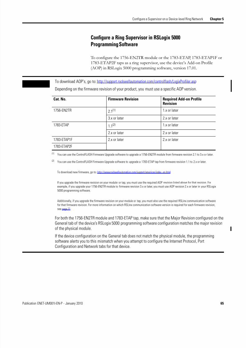
8/13/2019 EtherNet-IP Modules in Logix5000 Control Systems User Manual
http://slidepdf.com/reader/full/ethernet-ip-modules-in-logix5000-control-systems-user-manual 65/230
Publication ENET-UM001I-EN-P - January 2010 65
Configure a Supervisor on a Device-level Ring Network Chapter 5
Configure a Ring Supervisor in RSLogix 5000Programming Software
To configure the 1756-EN2TR module or the 1783-ETAP, 1783-ETAP1F or1783-ETAP2F taps as a ring supervisor, use the device’s Add-on Profile(AOP) in RSLogix 5000 programming software, version 17.01.
IMPORTANT To download AOP’s, go to: http://support.rockwellautomation.com/controlflash/LogixProfiler.asp
Depending on the firmware revision of your product, you must use a specific AOP version.
For both the 1756-EN2TR module and 1783-ETAP tap, make sure that the Major Revision configured on theGeneral tab of the device’s RSLogix 5000 programming software configuration matches the major revisionof the physical module.
If the device configuration on the General tab does not match the physical module, the programmingsoftware alerts you to this mismatch when you attempt to configure the Internet Protocol, PortConfiguration and Network tabs for that device.
Cat. No. Firmware Revision Required Add-on ProfileRevision
1756-EN2TR 2.1(1)
(1) You can use the ControlFLASH Firmware Upgrade software to upgrade a 1756-EN2TR module from firmware revision 2.1 to 3.x or later.
1.x or later
3.x or later 2.x or later
1783-ETAP 1.1(2)
(2) You can use the ControlFLASH Firmware Upgrade software to upgrade a 1783-ETAP tap from firmware revision 1.1 to 2.x or later.
To download new firmware, go to: http://www.rockwellautomation.com/support/americas/index_en.html
If you upgrade the firmware revision on your module or tap, you must use the required AOP revision listed above for that revision. Forexample, if you upgrade your 1756-EN2TR module to firmware revision 3.x or later, you must use AOP revision 2.x or later in your RSLogix
5000 programming software.
Additionally, if you upgrade the firmware revision on your module or tap, you must also use the required RSLinx communication software
for that firmware revision. For more information on which RSLinx communication software version is required for each firmware revision,
see page 71.
1.x or later
2.x or later 2.x or later
1783-ETAP1F 2.x or later 2.x or later
1783-ETAP2F
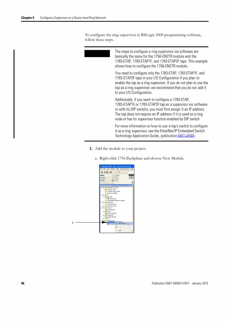
8/13/2019 EtherNet-IP Modules in Logix5000 Control Systems User Manual
http://slidepdf.com/reader/full/ethernet-ip-modules-in-logix5000-control-systems-user-manual 66/230
66 Publication ENET-UM001I-EN-P - January 2010
Chapter 5 Configure a Supervisor on a Device-level Ring Network
To configure the ring supervisor in RSLogix 5000 programming software,follow these steps.
1. Add the module to your project.
a. Right-click 1756 Backplane and choose New Module.
IMPORTANT The steps to configure a ring supervisor via software are
basically the same for the 1756-EN2TR module and the1783-ETAP, 1783-ETAP1F, and 1783-ETAP2F taps. This exampleshows how to configure the 1756-EN2TR module.
You need to configure only the 1783-ETAP, 1783-ETAP1F, and1783-ETAP2F taps in your I/O Configuration if you plan toenable the tap as a ring supervisor. If you do not plan to use thetap as a ring supervisor, we recommend that you do not add itto your I/O Configuration.
Additionally, if you want to configure a 1783-ETAP,1783-ETAP1F, or 1783-ETAP2F tap as a supervisor via softwareor with its DIP switchs, you must first assign it an IP address.
The tap does not require an IP address if it is used as a ringnode or has its supervisor function enabled by DIP switch
For more information on how to use a tap’s switch to configureit as a ring supervisor, see the EtherNet/IP Embedded SwitchTechnology Application Guide, publication ENET-AP005.
a
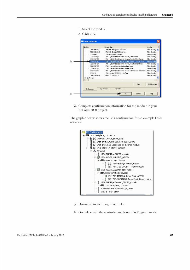
8/13/2019 EtherNet-IP Modules in Logix5000 Control Systems User Manual
http://slidepdf.com/reader/full/ethernet-ip-modules-in-logix5000-control-systems-user-manual 67/230
Publication ENET-UM001I-EN-P - January 2010 67
Configure a Supervisor on a Device-level Ring Network Chapter 5
b. Select the module.
c. Click OK.
2. Complete configuration information for the module in yourRSLogix 5000 project.
The graphic below shows the I/O configuration for an example DLRnetwork.
3. Download to your Logix controller.
4. Go online with the controller and leave it in Program mode.
b
c

8/13/2019 EtherNet-IP Modules in Logix5000 Control Systems User Manual
http://slidepdf.com/reader/full/ethernet-ip-modules-in-logix5000-control-systems-user-manual 68/230
68 Publication ENET-UM001I-EN-P - January 2010
Chapter 5 Configure a Supervisor on a Device-level Ring Network
Enable Ring Supervisor in RSLogix 5000 Programming Software
To enable a ring supervisor, you must use an AOP in RSLogix 5000programming software, version 17.01. After you have added your
1756-EN2TR module or 1783-ETAP, 1783-ETAP1F, or 1783-ETAP2F tap toyour RSLogix 5000 project, you must enable the ring supervisor.
To enable the 1756-EN2TR module or 1783-ETAP, 1783-ETAP1F, or1783-ETAP2F tap as a ring supervisor, follow these steps.
1. With your project online with the controller, double-click asupervisor-capable device in the I/O configuration tree.
IMPORTANT If you are using RSLogix 5000 programming software toconfigure your ring supervisor and monitor diagnostics of yourDLR network, you must be online with your controller.
IMPORTANT The steps to enable a ring supervisor are basically the same forboth the 1756-EN2TR module and the 1783-ETAP, 1783-ETAP1F,or 1783-ETAP2F tap. This example shows how to do it for the1756-EN2TR module.
Double-click the
module.

8/13/2019 EtherNet-IP Modules in Logix5000 Control Systems User Manual
http://slidepdf.com/reader/full/ethernet-ip-modules-in-logix5000-control-systems-user-manual 69/230
Publication ENET-UM001I-EN-P - January 2010 69
Configure a Supervisor on a Device-level Ring Network Chapter 5
2. Click the Network tab to enable Supervisor Mode.
Configuration takes affect immediately; you do not need to click Applyor OK.
3. Click the Advanced button to configure supervisor-related parameters,as shown in the screen shot below.
For the Supervisor Precedence parameter, you must click Set afterentering a value.
4. Click Set.
Click here to enable
Supervisor Mode.
IMPORTANT For Beacon Interval, Beacon Timeout and Ring Protocol VLANID, we recommend that you only use the default values.
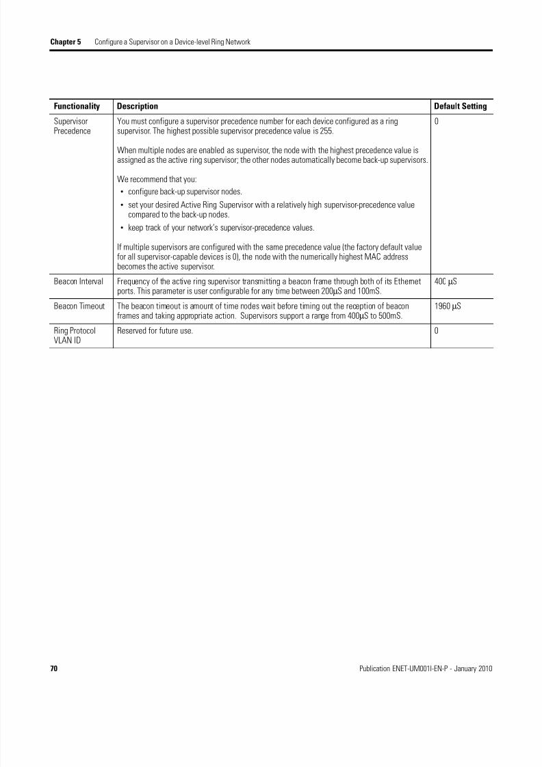
8/13/2019 EtherNet-IP Modules in Logix5000 Control Systems User Manual
http://slidepdf.com/reader/full/ethernet-ip-modules-in-logix5000-control-systems-user-manual 70/230
70 Publication ENET-UM001I-EN-P - January 2010
Chapter 5 Configure a Supervisor on a Device-level Ring Network
Functionality Description Default Setting
Supervisor
Precedence
You must configure a supervisor precedence number for each device configured as a ring
supervisor. The highest possible supervisor precedence value is 255.
When multiple nodes are enabled as supervisor, the node with the highest precedence value isassigned as the active ring supervisor; the other nodes automatically become back-up supervisors.
We recommend that you:
• configure back-up supervisor nodes.
• set your desired Active Ring Supervisor with a relatively high supervisor-precedence valuecompared to the back-up nodes.
• keep track of your network’s supervisor-precedence values.
If multiple supervisors are configured with the same precedence value (the factory default valuefor all supervisor-capable devices is 0), the node with the numerically highest MAC address
becomes the active supervisor.
0
Beacon Interval Frequency of the active ring supervisor transmitting a beacon frame through both of its Ethernetports. This parameter is user configurable for any time between 200µS and 100mS.
400 µS
Beacon Timeout The beacon timeout is amount of time nodes wait before timing out the reception of beaconframes and taking appropriate action. Supervisors support a range from 400µS to 500mS.
1960 µS
Ring ProtocolVLAN ID
Reserved for future use. 0
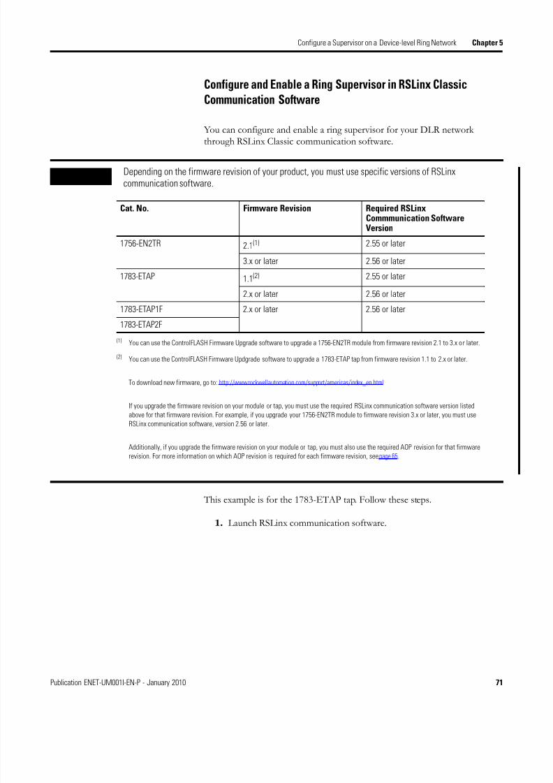
8/13/2019 EtherNet-IP Modules in Logix5000 Control Systems User Manual
http://slidepdf.com/reader/full/ethernet-ip-modules-in-logix5000-control-systems-user-manual 71/230
Publication ENET-UM001I-EN-P - January 2010 71
Configure a Supervisor on a Device-level Ring Network Chapter 5
Configure and Enable a Ring Supervisor in RSLinx ClassicCommunication Software
You can configure and enable a ring supervisor for your DLR networkthrough RSLinx Classic communication software.
This example is for the 1783-ETAP tap. Follow these steps.
1. Launch RSLinx communication software.
IMPORTANT Depending on the firmware revision of your product, you must use specific versions of RSLinxcommunication software.
Cat. No. Firmware Revision Required RSLinxCommmunication SoftwareVersion
1756-EN2TR 2.1(1)
(1) You can use the ControlFLASH Firmware Upgrade software to upgrade a 1756-EN2TR module from firmware revision 2.1 to 3.x or later.
2.55 or later
3.x or later 2.56 or later
1783-ETAP 1.1(2)
(2) You can use the ControlFLASH Firmware Updgrade software to upgrade a 1783-ETAP tap from firmware revision 1.1 to 2.x or later.
To download new firmware, go to: http://www.rockwellautomation.com/support/americas/index_en.html
If you upgrade the firmware revision on your module or tap, you must use the required RSLinx communication software version listed
above for that firmware revision. For example, if you upgrade your 1756-EN2TR module to firmware revision 3.x or later, you must use
RSLinx communication software, version 2.56 or later.
Additionally, if you upgrade the firmware revision on your module or tap, you must also use the required AOP revision for that firmware
revision. For more information on which AOP revision is required for each firmware revision, see page 65.
2.55 or later
2.x or later 2.56 or later
1783-ETAP1F 2.x or later 2.56 or later
1783-ETAP2F

8/13/2019 EtherNet-IP Modules in Logix5000 Control Systems User Manual
http://slidepdf.com/reader/full/ethernet-ip-modules-in-logix5000-control-systems-user-manual 72/230
72 Publication ENET-UM001I-EN-P - January 2010
Chapter 5 Configure a Supervisor on a Device-level Ring Network
2. Browse to the DLR network that you are setting up.
3. Access the supervisor-capable node’s properties.
a. Right-click the node.
b. Choose Module Configuration.
The General tab appears with information about the module that is notconfigurable.
TIP If you do not have the Electronic Data Sheet (EDS) file installedon the module configured to be the ring supervisor, it willappear with a question mark (?). To obtain and use the EDS file:
• right-click the module and choose to upload the EDS file from thedevice.
or
• download the EDS file from:http://www.rockwellautomation.com/resources/eds/
a
b

8/13/2019 EtherNet-IP Modules in Logix5000 Control Systems User Manual
http://slidepdf.com/reader/full/ethernet-ip-modules-in-logix5000-control-systems-user-manual 73/230
Publication ENET-UM001I-EN-P - January 2010 73
Configure a Supervisor on a Device-level Ring Network Chapter 5
4. Click the Network tab to enable Supervisor Mode.
Configuration takes affect immediately; you do not need to click Applyor OK.
5. Click the Advanced button to configure supervisor-related parameters.
6. Click Set.
Click here to enable
Supervisor Mode.
IMPORTANT For Beacon Interval, Beacon Timeout and Ring Protocol VLANID, we recommend that you only use the default values.
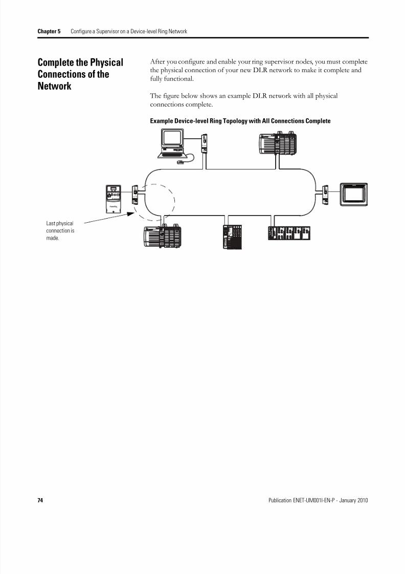
8/13/2019 EtherNet-IP Modules in Logix5000 Control Systems User Manual
http://slidepdf.com/reader/full/ethernet-ip-modules-in-logix5000-control-systems-user-manual 74/230
74 Publication ENET-UM001I-EN-P - January 2010
Chapter 5 Configure a Supervisor on a Device-level Ring Network
Complete the PhysicalConnections of theNetwork
After you configure and enable your ring supervisor nodes, you must completethe physical connection of your new DLR network to make it complete andfully functional.
The figure below shows an example DLR network with all physicalconnections complete.
Example Device-level Ring Topology with All Connections Complete
Last physical
connection is
made.

8/13/2019 EtherNet-IP Modules in Logix5000 Control Systems User Manual
http://slidepdf.com/reader/full/ethernet-ip-modules-in-logix5000-control-systems-user-manual 75/230
Publication ENET-UM001I-EN-P - January 2010 75
Configure a Supervisor on a Device-level Ring Network Chapter 5
Verify SupervisorConfiguration
You may want to verify that your supervisor configuration has taken place andthat the ring network is functioning properly. You can verify that configurationand a normally functioning network in either RSLogix 5000 programmingsoftware or RSLinx Classic software.
1. Access the module properties as shown previously in this chapter.
2. Click the Network tab.
3. Check the Network Topology and Network Status fields.
They should display Ring and Normal respectively, as shown below.
For a 1756-EN2TR module, you can also verify the supervisor configurationthrough the module’s diagnostic web pages. For more information onmonitoring diagnostics via an EtherNet/IP module’s web pages, see MonitorDiagnostics on page 137.
Troubleshoot DLRNetwork Issues
For a full description of how to troubleshoot DLR network issues, such asreplacing a node on a DLR network, see the EtherNet/IP Embedded Switch Technology Application Guide, publication ENET-AP005.
Check these fields.

8/13/2019 EtherNet-IP Modules in Logix5000 Control Systems User Manual
http://slidepdf.com/reader/full/ethernet-ip-modules-in-logix5000-control-systems-user-manual 76/230
76 Publication ENET-UM001I-EN-P - January 2010
Chapter 5 Configure a Supervisor on a Device-level Ring Network
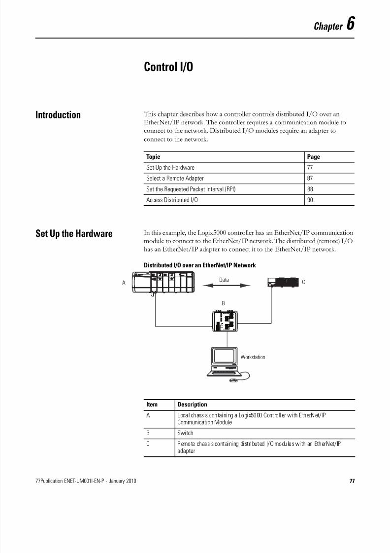
8/13/2019 EtherNet-IP Modules in Logix5000 Control Systems User Manual
http://slidepdf.com/reader/full/ethernet-ip-modules-in-logix5000-control-systems-user-manual 77/230
77Publication ENET-UM001I-EN-P - January 2010 77
Chapter 6
Control I/O
Introduction This chapter describes how a controller controls distributed I/O over anEtherNet/IP network. The controller requires a communication module toconnect to the network. Distributed I/O modules require an adapter to
connect to the network.
Set Up the Hardware In this example, the Logix5000 controller has an EtherNet/IP communicationmodule to connect to the EtherNet/IP network. The distributed (remote) I/Ohas an EtherNet/IP adapter to connect it to the EtherNet/IP network.
Distributed I/O over an EtherNet/IP Network
Topic Page
Set Up the Hardware 77
Select a Remote Adapter 87
Set the Requested Packet Interval (RPI) 88
Access Distributed I/O 90
A CData
B
Workstation
Item Description
A Local chassis containing a Logix5000 Controller with EtherNet/IPCommunication Module
B Switch
C Remote chassis containing distributed I/O modules with an EtherNet/IPadapter
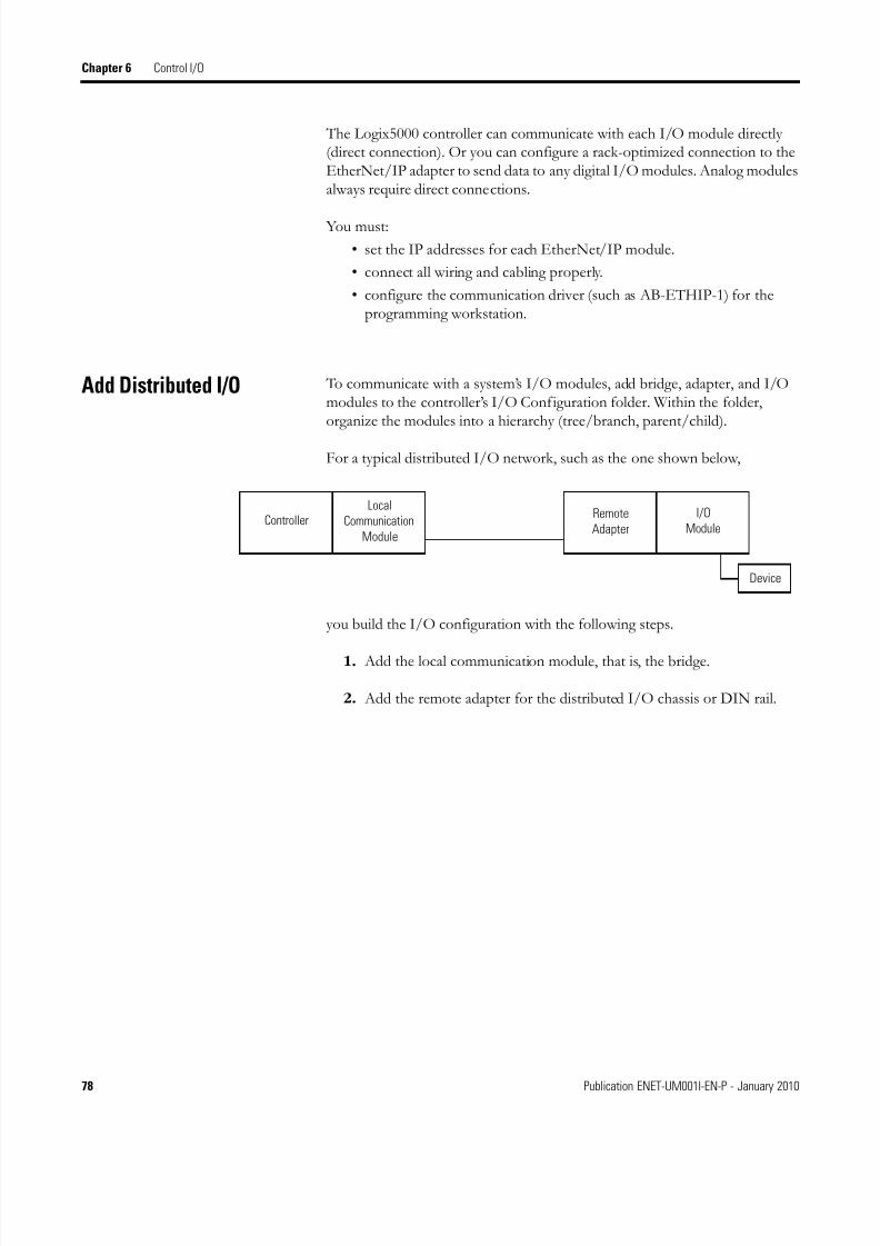
8/13/2019 EtherNet-IP Modules in Logix5000 Control Systems User Manual
http://slidepdf.com/reader/full/ethernet-ip-modules-in-logix5000-control-systems-user-manual 78/230
78 Publication ENET-UM001I-EN-P - January 2010
Chapter 6 Control I/O
The Logix5000 controller can communicate with each I/O module directly(direct connection). Or you can configure a rack-optimized connection to theEtherNet/IP adapter to send data to any digital I/O modules. Analog modulesalways require direct connections.
You must:
• set the IP addresses for each EtherNet/IP module.
• connect all wiring and cabling properly.
• configure the communication driver (such as AB-ETHIP-1) for theprogramming workstation.
Add Distributed I/O To communicate with a system’s I/O modules, add bridge, adapter, and I/Omodules to the controller’s I/O Configuration folder. Within the folder,organize the modules into a hierarchy (tree/branch, parent/child).
For a typical distributed I/O network, such as the one shown below,
you build the I/O configuration with the following steps.
1. Add the local communication module, that is, the bridge.
2. Add the remote adapter for the distributed I/O chassis or DIN rail.
Local
Communication
Module
Device
ControllerI/O
ModuleRemote
Adapter

8/13/2019 EtherNet-IP Modules in Logix5000 Control Systems User Manual
http://slidepdf.com/reader/full/ethernet-ip-modules-in-logix5000-control-systems-user-manual 79/230
Publication ENET-UM001I-EN-P - January 2010 79
Control I/O Chapter 6
3. Add the I/O module.
Add a Module
To add a module to the I/O Configuration folder, perform this procedure.
1. In the Controller Organizer of RSLogix 5000 programming software,right-click branch to which you want to add the module and chooseNew Module.
The Select Module dialog box appears.
IMPORTANT I/O is controlled on the same subnet and can’t be processed viaa router.

8/13/2019 EtherNet-IP Modules in Logix5000 Control Systems User Manual
http://slidepdf.com/reader/full/ethernet-ip-modules-in-logix5000-control-systems-user-manual 80/230
80 Publication ENET-UM001I-EN-P - January 2010
Chapter 6 Control I/O
2. Expand the module type and choose the module you wish to add andclick OK.
The Select Major Revision dialog box appears.
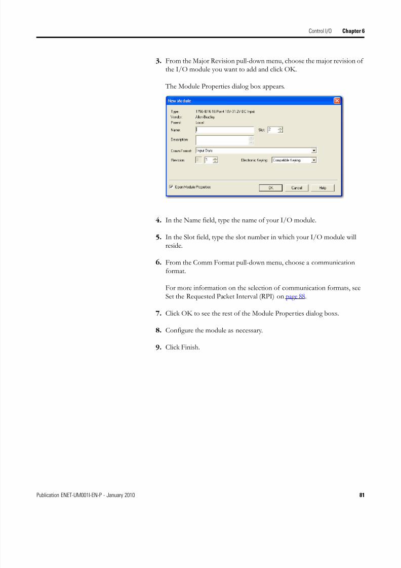
8/13/2019 EtherNet-IP Modules in Logix5000 Control Systems User Manual
http://slidepdf.com/reader/full/ethernet-ip-modules-in-logix5000-control-systems-user-manual 81/230
Publication ENET-UM001I-EN-P - January 2010 81
Control I/O Chapter 6
3. From the Major Revision pull-down menu, choose the major revision ofthe I/O module you want to add and click OK.
The Module Properties dialog box appears.
4. In the Name field, type the name of your I/O module.
5. In the Slot field, type the slot number in which your I/O module willreside.
6. From the Comm Format pull-down menu, choose a communicationformat.
For more information on the selection of communication formats, see
Set the Requested Packet Interval (RPI) on page 88.
7. Click OK to see the rest of the Module Properties dialog boxs.
8. Configure the module as necessary.
9. Click Finish.

8/13/2019 EtherNet-IP Modules in Logix5000 Control Systems User Manual
http://slidepdf.com/reader/full/ethernet-ip-modules-in-logix5000-control-systems-user-manual 82/230
82 Publication ENET-UM001I-EN-P - January 2010
Chapter 6 Control I/O
Select a CommunicationFormat
When configuring an I/O module, select its communication format. Thechosen communication format determines the data structure for the module’stags. Many I/O modules support different formats. Each format uses adifferent data structure. The chosen communication format determines:
• direct or rack-optimized connection.• ownership.
See online help in RSLogix 5000 programming software for specificcommunication formats per I/O module.
Communication Formats
Type of I/Omodule
Desired Connection Type Required Communication FormatThat Specifies
Digital A rack-optimized connection Rack Optimization
To use specialty features of themodule, such as diagnostics,timestamps, or electronic fuses
Full Diagnostics
CST Timestamped
Digital A direct connection Scheduled Data
Input Data
Output Data
Analog A direct connection
(only direct connection issupported for analog modules)
Float Data
Integer Data
CST Timestamped
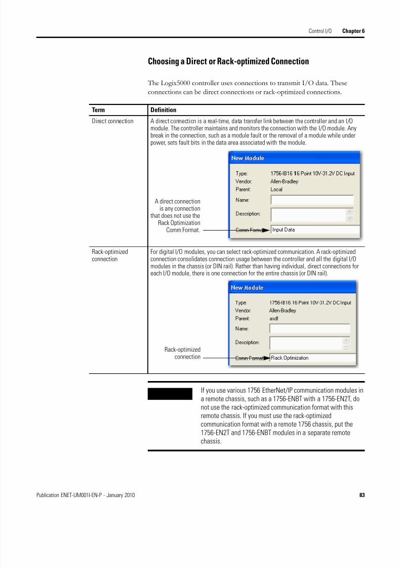
8/13/2019 EtherNet-IP Modules in Logix5000 Control Systems User Manual
http://slidepdf.com/reader/full/ethernet-ip-modules-in-logix5000-control-systems-user-manual 83/230
Publication ENET-UM001I-EN-P - January 2010 83
Control I/O Chapter 6
Choosing a Direct or Rack-optimized Connection
The Logix5000 controller uses connections to transmit I/O data. These
connections can be direct connections or rack-optimized connections.
Term Definition
Direct connection A direct connection is a real-time, data transfer link between the controller and an I/Omodule. The controller maintains and monitors the connection with the I/O module. Anybreak in the connection, such as a module fault or the removal of a module while underpower, sets fault bits in the data area associated with the module.
Rack-optimizedconnection
For digital I/O modules, you can select rack-optimized communication. A rack-optimizedconnection consolidates connection usage between the controller and all the digital I/Omodules in the chassis (or DIN rail). Rather than having individual, direct connections foreach I/O module, there is one connection for the entire chassis (or DIN rail).
A direct connectionis any connection
that does not use theRack Optimization
Comm Format.
Rack-optimizedconnection
IMPORTANT If you use various 1756 EtherNet/IP communication modules in
a remote chassis, such as a 1756-ENBT with a 1756-EN2T, donot use the rack-optimized communication format with thisremote chassis. If you must use the rack-optimizedcommunication format with a remote 1756 chassis, put the1756-EN2T and 1756-ENBT modules in a separate remotechassis.

8/13/2019 EtherNet-IP Modules in Logix5000 Control Systems User Manual
http://slidepdf.com/reader/full/ethernet-ip-modules-in-logix5000-control-systems-user-manual 84/230
84 Publication ENET-UM001I-EN-P - January 2010
Chapter 6 Control I/O
Direct Connections For I/O Modules
In this example, assume that each distributed I/O module is configured for adirect connection to the controller.
If you have many modules, direct connections to each module may not befeasible because you could use up the number of connections and packets persecond supported by the module.
See Rack-optimized Connections For I/O Modules on page 85 to conserveconnection use and network traffic.
EtherNet/IP Network
Controller With EtherNet/IP
Communication Module
EtherNet/IP Adapters
With I/O Modules
Digital I/O Modules Analog I/O Modules Digital I/O Modules
Switch
Example - System Connections
System Connections Amount
Controller to local EtherNet/IP communication module 0
Controller to EtherNet/IP adapterDirect connection for digital I/O module
Direct connection for analog I/O module
4
2
Total connections used 6
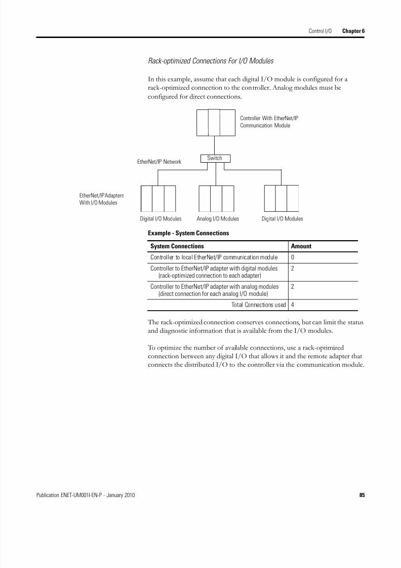
8/13/2019 EtherNet-IP Modules in Logix5000 Control Systems User Manual
http://slidepdf.com/reader/full/ethernet-ip-modules-in-logix5000-control-systems-user-manual 85/230
Publication ENET-UM001I-EN-P - January 2010 85
Control I/O Chapter 6
Rack-optimized Connections For I/O Modules
In this example, assume that each digital I/O module is configured for arack-optimized connection to the controller. Analog modules must be
configured for direct connections.
The rack-optimized connection conserves connections, but can limit the statusand diagnostic information that is available from the I/O modules.
To optimize the number of available connections, use a rack-optimizedconnection between any digital I/O that allows it and the remote adapter thatconnects the distributed I/O to the controller via the communication module.
EtherNet/IP Network
Controller With EtherNet/IP
Communication Module
EtherNet/IP Adapters
With I/O Modules
Digital I/O Modules Analog I/O Modules Digital I/O Modules
Switch
Example - System Connections
System Connections Amount
Controller to local EtherNet/IP communication module 0
Controller to EtherNet/IP adapter with digital modules(rack-optimized connection to each adapter)
2
Controller to EtherNet/IP adapter with analog modules(direct connection for each analog I/O module)
2
Total Connections used 4

8/13/2019 EtherNet-IP Modules in Logix5000 Control Systems User Manual
http://slidepdf.com/reader/full/ethernet-ip-modules-in-logix5000-control-systems-user-manual 86/230
86 Publication ENET-UM001I-EN-P - January 2010
Chapter 6 Control I/O
Ownership
In a Logix5000 system, modules multicast data. Therefore, multiple modulescan receive the same data at the same time from a single module. When
choosing a communication format, decide whether to establish anowner-controller or listen-only relationship with the module.
Types of Module Ownership
Owner controller The controller that creates the primary configuration and communication connection to a module. The ownercontroller writes configuration data and can establish a connection to the module.
Listen-only connection An I/O connection where another controller owns/provides the configuration data for the I/O module. Acontroller using a listen-only connection only monitors the module. It does not write configuration data andcan only maintain a connection to the I/O module when the owner controller is actively controlling the I/Omodule.
An owner connection is anyconnection that does not includeListen-Only in its Comm Format.
Listen-only connection
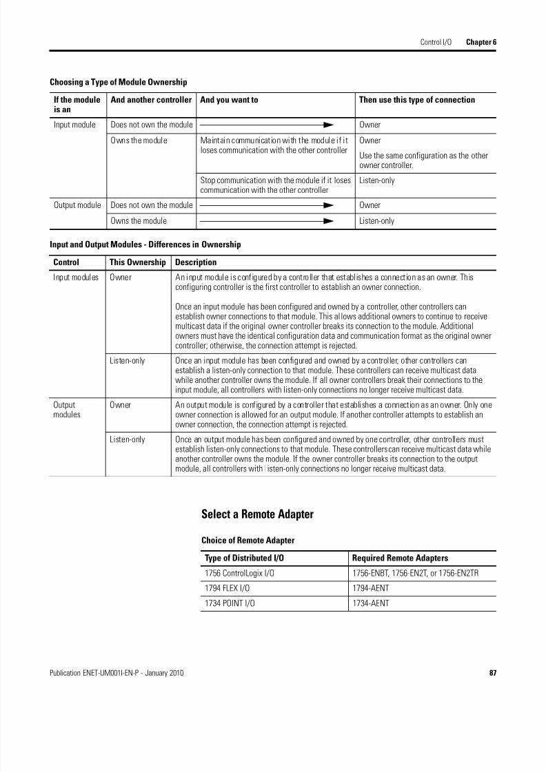
8/13/2019 EtherNet-IP Modules in Logix5000 Control Systems User Manual
http://slidepdf.com/reader/full/ethernet-ip-modules-in-logix5000-control-systems-user-manual 87/230
Publication ENET-UM001I-EN-P - January 2010 87
Control I/O Chapter 6
Select a Remote Adapter
Choosing a Type of Module Ownership
If the moduleis an
And another controller And you want to Then use this type of connection
Input module Does not own the module Owner
Owns the module Maintain communication with the module if itloses communication with the other controller
Owner
Use the same configuration as the otherowner controller.
Stop communication with the module if it losescommunication with the other controller
Listen-only
Output module Does not own the module Owner
Owns the module Listen-only
Input and Output Modules - Differences in Ownership
Control This Ownership Description
Input modules Owner An input module is configured by a controller that establishes a connection as an owner. Thisconfiguring controller is the first controller to establish an owner connection.
Once an input module has been configured and owned by a controller, other controllers canestablish owner connections to that module. This allows additional owners to continue to receivemulticast data if the original owner controller breaks its connection to the module. Additionalowners must have the identical configuration data and communication format as the original ownercontroller; otherwise, the connection attempt is rejected.
Listen-only Once an input module has been configured and owned by a controller, other controllers canestablish a listen-only connection to that module. These controllers can receive multicast datawhile another controller owns the module. If all owner controllers break their connections to theinput module, all controllers with listen-only connections no longer receive multicast data.
Outputmodules
Owner An output module is configured by a controller that establishes a connection as an owner. Only oneowner connection is allowed for an output module. If another controller attempts to establish anowner connection, the connection attempt is rejected.
Listen-only Once an output module has been configured and owned by one controller, other controllers mustestablish listen-only connections to that module. These controllers can receive multicast data whileanother controller owns the module. If the owner controller breaks its connection to the outputmodule, all controllers with l isten-only connections no longer receive multicast data.
Choice of Remote Adapter
Type of Distributed I/O Required Remote Adapters
1756 ControlLogix I/O 1756-ENBT, 1756-EN2T, or 1756-EN2TR
1794 FLEX I/O 1794-AENT
1734 POINT I/O 1734-AENT

8/13/2019 EtherNet-IP Modules in Logix5000 Control Systems User Manual
http://slidepdf.com/reader/full/ethernet-ip-modules-in-logix5000-control-systems-user-manual 88/230
88 Publication ENET-UM001I-EN-P - January 2010
Chapter 6 Control I/O
Set the Requested PacketInterval (RPI)
When you configure an I/O module, you define the requested packet interval(RPI) rate for the module. Only data-producing modules require an RPI. Forexample, a local EtherNet/IP communication module requires no RPIbecause it produces no data for the system but acts only as a bridge.
To set an RPI, perform this procedure.
1. Make sure the module is installed, started and connected to thecontroller via a serial, or other network, connection.
2. In the Controller Organizer of RSLogix 5000 programming software,right-click the EtherNet/IP module and choose Properties.
The Module Properties dialog box appears.
3. Click the Connection tab.

8/13/2019 EtherNet-IP Modules in Logix5000 Control Systems User Manual
http://slidepdf.com/reader/full/ethernet-ip-modules-in-logix5000-control-systems-user-manual 89/230
Publication ENET-UM001I-EN-P - January 2010 89
Control I/O Chapter 6
4. From the Requested Packet Interval (RPI) menu, select the rate at whichyou want data to be updated over a connection.
Only set the RPI to the rate the application requires.
5. Click OK.
Unlike EtherNet/IP modules, in Logix5000 controllers, I/O values update atan interval set via the project’s I/O configuration folder. The values update
asynchronously to the execution of logic. At the specified interval, thecontroller updates a value independently from the execution of logic.
IMPORTANT The RPI determines the number of packets per secondthat the module will produce on a connection. Eachmodule can only produce a limited number of packetsper second. Exceeding this limit prevents the modulefrom opening more connections.
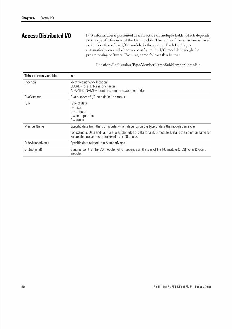
8/13/2019 EtherNet-IP Modules in Logix5000 Control Systems User Manual
http://slidepdf.com/reader/full/ethernet-ip-modules-in-logix5000-control-systems-user-manual 90/230
90 Publication ENET-UM001I-EN-P - January 2010
Chapter 6 Control I/O
Access Distributed I/O I/O information is presented as a structure of multiple fields, which dependson the specific features of the I/O module. The name of the structure is basedon the location of the I/O module in the system. Each I/O tag isautomatically created when you configure the I/O module through theprogramming software. Each tag name follows this format:
Location:SlotNumber:Type.MemberName.SubMemberName.Bit
This address variable Is
Location Identifies network locationLOCAL = local DIN rail or chassisADAPTER_NAME = identifies remote adapter or bridge
SlotNumber Slot number of I/O module in its chassis
Type Type of dataI = inputO = output
C = configurationS = status
MemberName Specific data from the I/O module, which depends on the type of data the module can store
For example, Data and Fault are possible fields of data for an I/O module. Data is the common name forvalues the are sent to or received from I/O points.
SubMemberName Specific data related to a MemberName
Bit (optional) Specific point on the I/O module, which depends on the size of the I/O module (0...31 for a 32-pointmodule)

8/13/2019 EtherNet-IP Modules in Logix5000 Control Systems User Manual
http://slidepdf.com/reader/full/ethernet-ip-modules-in-logix5000-control-systems-user-manual 91/230
Publication ENET-UM001I-EN-P - January 2010 91
Control I/O Chapter 6
EXAMPLE
1
23
4
Example Module Example Tag Names (automatically created by the software)
1 Remote 1794-AENT adapter“FLEX_io_adapter”
FLEX_io_adapter:IFLEX_io_adapter:I.SlotStatusBitsFLEX_io_adapter:I.Data
FLEX_io_adapter:OFLEX_io_adapter:O.Data
2 Remote 1794-IA16 “input_module” in slot 0
Rack-optimized connection
FLEX_io_adapter:0:CFLEX_io_adapter:0:C.ConfigFLEX_io_adapter:0:C.DelayTime_0FLEX_io_adapter:0:C.DelayTime_1FLEX_io_adapter:0:C.DelayTime_2FLEX_io_adapter:0:C.DelayTime_3FLEX_io_adapter:0:C.DelayTime_4FLEX_io_adapter:0:C.DelayTime_5
FLEX_io_adapter:0:I
3 Remote 1794-OB16 “output_module” in slot 1
Rack-optimized connection
FLEX_io_adapter:1:CFLEX_io_adapter:1:C.SSData
FLEX_io_adapter:1:OFLEX_io_adapter:1:O.Data
4 Remote 1794-IF2XOF2I “combo_analog” in slot 2
Direct connection
FLEX_io_adapter:2:CFLEX_io_adapter:2:C.InputFIlterFLEX_io_adapter:2:C.InputConfigurationFLEX_io_adapter:2:C.OutputConfigurationFLEX_io_adapter:2:C.RTSIntervalFLEX_io_adapter:2:C.SSCh0OuputData
FLEX_io_adapter:2:C.SSCH1OutputDataFLEX_io_adapter:2:I

8/13/2019 EtherNet-IP Modules in Logix5000 Control Systems User Manual
http://slidepdf.com/reader/full/ethernet-ip-modules-in-logix5000-control-systems-user-manual 92/230
92 Publication ENET-UM001I-EN-P - January 2010
Chapter 6 Control I/O
The choice of rack optimization for an I/O module creates tags as aliases forthe adapter module’s tags. This logic displays the device’s tag as an alias for athe adapter module’s tag. In this example, the tag name of the adapter is inangle brackets.
Additional Resources This document contains additional information on controlling I/O:
EtherNet/IP Performance Application Solution, publication ENET-AP001.
Conveyor:2:I.0
<Conveyor:I.Data[2].0>
Tag Name of the I/O Device Tag Name of the Adapter
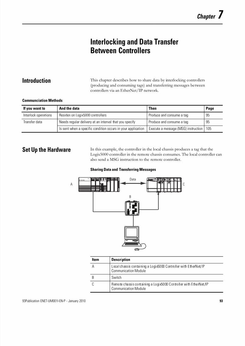
8/13/2019 EtherNet-IP Modules in Logix5000 Control Systems User Manual
http://slidepdf.com/reader/full/ethernet-ip-modules-in-logix5000-control-systems-user-manual 93/230
93Publication ENET-UM001I-EN-P - January 2010 93
Chapter 7
Interlocking and Data TransferBetween Controllers
Introduction This chapter describes how to share data by interlocking controllers(producing and consuming tags) and transferring messages betweencontrollers via an EtherNet/IP network.
Set Up the Hardware In this example, the controller in the local chassis produces a tag that theLogix5000 controller in the remote chassis consumes. The local controller canalso send a MSG instruction to the remote controller.
Sharing Data and Transferring Messages
Communciation Methods
If you want to And the data Then Page
Interlock operations Resides on Logix5000 controllers Produce and consume a tag 95
Transfer data Needs regular delivery at an interval that you specify Produce and consume a tag 95
Is sent when a specific condition occurs in your application Execute a message (MSG) instruction 105
Data
B
A C
Item Description
A Local chassis containing a Logix5000 Controller with EtherNet/IPCommunication Module
B Switch
C Remote chassis containing a Logix5000 Controller with EtherNet/IPCommunication Module

8/13/2019 EtherNet-IP Modules in Logix5000 Control Systems User Manual
http://slidepdf.com/reader/full/ethernet-ip-modules-in-logix5000-control-systems-user-manual 94/230
94 Publication ENET-UM001I-EN-P - January 2010
Chapter 7 Interlocking and Data Transfer Between Controllers
Logix5000 Controller Combinations
Make sure to:
• set the IP addresses and other network parameters for eachEtherNet/IP communication module.
• connect all wiring and cabling.
• configure the communication driver (such as AB-ETHIP-1) for theprogramming workstation
Choosing a Communication Module
Controllers Communication Modules
1756 ControlLogix 1756-ENBT, 1756-EN2T, 1756-EN2TR,1756-EN2TXT, or 1756-EN2F communicationmodule
1768 CompactLogix 1768-ENBT communication module
1769-L23E-QB1B, 1769-L23E-QBFC1B,1769-L32E and 1769-L35E CompactLogix
A built-in EtherNet/IP port
1794 FlexLogix 1788-ENBT EtherNet/IP communicationcard
PowerFlex 700S with DriveLogix controller 1788-ENBT EtherNet/IP communicationcard
IMPORTANT If you are sharing tags between ControlLogix controllers andthe controllers are sharing only tags, not sending messages, setthe communication format of the 1756-ENBT, 1756-EN2F,1756-EN2T, or 1756-EN2TXT module to None.
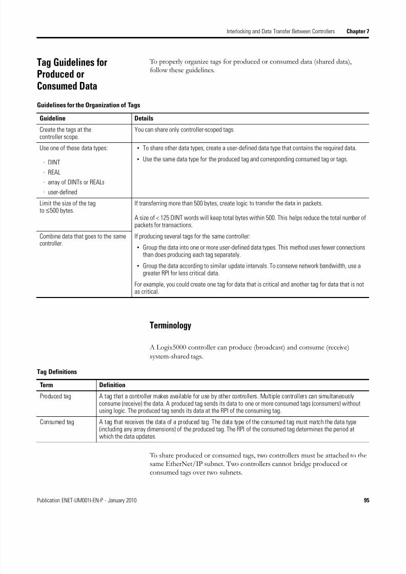
8/13/2019 EtherNet-IP Modules in Logix5000 Control Systems User Manual
http://slidepdf.com/reader/full/ethernet-ip-modules-in-logix5000-control-systems-user-manual 95/230
Publication ENET-UM001I-EN-P - January 2010 95
Interlocking and Data Transfer Between Controllers Chapter 7
Tag Guidelines forProduced orConsumed Data
To properly organize tags for produced or consumed data (shared data),follow these guidelines.
Terminology
A Logix5000 controller can produce (broadcast) and consume (receive)
system-shared tags.
To share produced or consumed tags, two controllers must be attached to thesame EtherNet/IP subnet. Two controllers cannot bridge produced orconsumed tags over two subnets.
Guidelines for the Organization of Tags
Guideline Details
Create the tags at thecontroller scope.
You can share only controller-scoped tags.
Use one of these data types:
· DINT
· REAL
· array of DINTs or REALs
· user-defined
• To share other data types, create a user-defined data type that contains the required data.
• Use the same data type for the produced tag and corresponding consumed tag or tags.
Limit the size of the tag to ≤ 500 bytes.
If transferring more than 500 bytes, create logic to transfer the data in packets.
A size of < 125 DINT words will keep total bytes within 500. This helps reduce the total number ofpackets for transactions.
Combine data that goes to the samecontroller.
If producing several tags for the same controller:
• Group the data into one or more user-defined data types. This method uses fewer connectionsthan does producing each tag separately.
• Group the data according to similar update intervals. To conserve network bandwidth, use agreater RPI for less critical data.
For example, you could create one tag for data that is critical and another tag for data that is notas critical.
Tag Definitions
Term Definition
Produced tag A tag that a controller makes available for use by other controllers. Multiple controllers can simultaneously
consume (receive) the data. A produced tag sends its data to one or more consumed tags (consumers) withoutusing logic. The produced tag sends its data at the RPI of the consuming tag.
Consumed tag A tag that receives the data of a produced tag. The data type of the consumed tag must match the data type(including any array dimensions) of the produced tag. The RPI of the consumed tag determines the period atwhich the data updates.
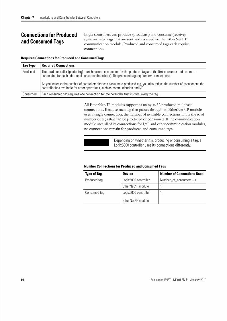
8/13/2019 EtherNet-IP Modules in Logix5000 Control Systems User Manual
http://slidepdf.com/reader/full/ethernet-ip-modules-in-logix5000-control-systems-user-manual 96/230
96 Publication ENET-UM001I-EN-P - January 2010
Chapter 7 Interlocking and Data Transfer Between Controllers
Connections for Producedand Consumed Tags
Logix controllers can produce (broadcast) and consume (receive)system-shared tags that are sent and received via the EtherNet/IPcommunication module. Produced and consumed tags each requireconnections.
All EtherNet/IP modules support as many as 32 produced multicastconnections. Because each tag that passes through an EtherNet/IP moduleuses a single connection, the number of available connections limits the totalnumber of tags that can be produced or consumed. If the communicationmodule uses all of its connections for I/O and other communication modules,no connections remain for produced and consumed tags.
Required Connections for Produced and Consumed Tags
Tag Type Required Connections
Produced The local controller (producing) must have one connection for the produced tag and the first consumer and one moreconnection for each additional consumer (heartbeat). The produced tag requires two connections.
As you increase the number of controllers that can consume a produced tag, you also reduce the number of connections thecontroller has available for other operations, such as communication and I/O.
Consumed Each consumed tag requires one connection for the controller that is consuming the tag.
IMPORTANT Depending on whether it is producing or consuming a tag, aLogix5000 controller uses its connections differently.
Number Connections for Produced and Consumed Tags
Type of Tag Device Number of Connections Used
Produced tag Logix5000 controller Number_of_consumers + 1
EtherNet/IP module 1
Consumed tag Logix5000 controller
EtherNet/IP module
1
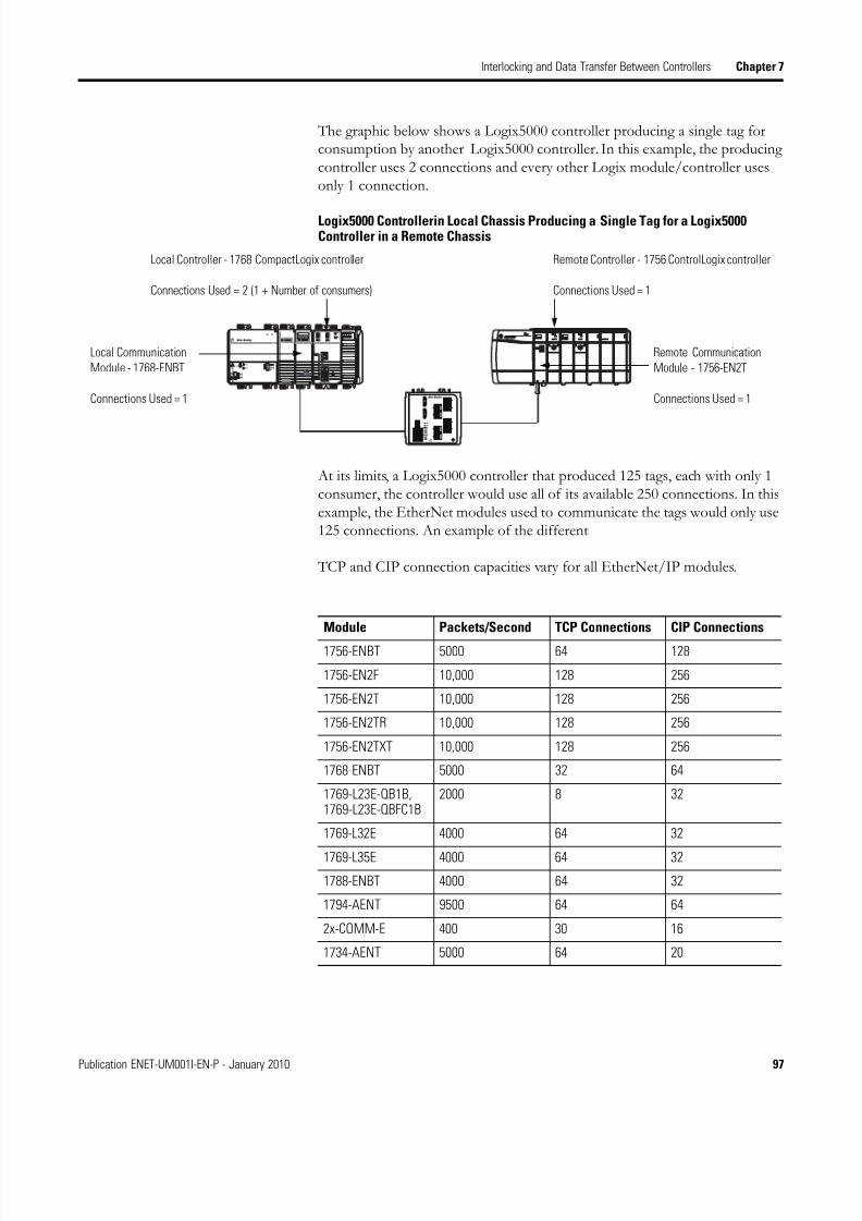
8/13/2019 EtherNet-IP Modules in Logix5000 Control Systems User Manual
http://slidepdf.com/reader/full/ethernet-ip-modules-in-logix5000-control-systems-user-manual 97/230
Publication ENET-UM001I-EN-P - January 2010 97
Interlocking and Data Transfer Between Controllers Chapter 7
The graphic below shows a Logix5000 controller producing a single tag forconsumption by another Logix5000 controller. In this example, the producingcontroller uses 2 connections and every other Logix module/controller usesonly 1 connection.
Logix5000 Controllerin Local Chassis Producing a Single Tag for a Logix5000Controller in a Remote Chassis
At its limits, a Logix5000 controller that produced 125 tags, each with only 1consumer, the controller would use all of its available 250 connections. In thisexample, the EtherNet modules used to communicate the tags would only use125 connections. An example of the different
TCP and CIP connection capacities vary for all EtherNet/IP modules.
Local Controller - 1768 CompactLogix controller
Connections Used = 2 (1 + Number of consumers)
Remote Controller - 1756 ControlLogix controller
Connections Used = 1
Local Communication
Module - 1768-ENBT
Connections Used = 1
Remote Communication
Module - 1756-EN2T
Connections Used = 1
Module Packets/Second TCP Connections CIP Connections
1756-ENBT 5000 64 128
1756-EN2F 10,000 128 256
1756-EN2T 10,000 128 256
1756-EN2TR 10,000 128 256
1756-EN2TXT 10,000 128 256
1768-ENBT 5000 32 64
1769-L23E-QB1B,1769-L23E-QBFC1B
2000 8 32
1769-L32E 4000 64 32
1769-L35E 4000 64 32
1788-ENBT 4000 64 32
1794-AENT 9500 64 64
2x-COMM-E 400 30 16
1734-AENT 5000 64 20

8/13/2019 EtherNet-IP Modules in Logix5000 Control Systems User Manual
http://slidepdf.com/reader/full/ethernet-ip-modules-in-logix5000-control-systems-user-manual 98/230
98 Publication ENET-UM001I-EN-P - January 2010
Chapter 7 Interlocking and Data Transfer Between Controllers
Produce a Tag To produce a tag, configure the produced tag in the RSLogix 5000 project forthe local (producer) controller. You do not have to configure the consumercontrollers in the I/O Configuration folder of the producer controller.
Configure the Produced Tag
To configure the produced tag, perform this procedure.
1. In the producer’s controller organizer in RSLogix 5000 programmingsoftware, right-click the Controller Tags folder and select Edit Tags.
The Controller Tags dialog box appears.
You can produce only controller-scoped tags.
2. In the Controller Tags window, right-click the tag that you want toproduce and choose Edit Tag Properties.

8/13/2019 EtherNet-IP Modules in Logix5000 Control Systems User Manual
http://slidepdf.com/reader/full/ethernet-ip-modules-in-logix5000-control-systems-user-manual 99/230
Publication ENET-UM001I-EN-P - January 2010 99
Interlocking and Data Transfer Between Controllers Chapter 7
The Tag Properties dialog box appears.
3. From the Type pull-down menu, select Produced.
4. Click Connection.
The Produced Tag Connection dialog box appears.
5. In the Max Consumers field, type the maximum number of controllersthat will consume (receive) the tag.
6. Click OK.

8/13/2019 EtherNet-IP Modules in Logix5000 Control Systems User Manual
http://slidepdf.com/reader/full/ethernet-ip-modules-in-logix5000-control-systems-user-manual 100/230
100 Publication ENET-UM001I-EN-P - January 2010
Chapter 7 Interlocking and Data Transfer Between Controllers
Consume Data Produced byAnother Controller
To consume a produced tag, specify both the producer controller and theproduced tag in the RSLogix 5000 project for the remote (consumer)Logix5000 controller.
Add the Producer Controller to the Consumer’s I/O Configuration
Add the producer controller to the remote controller’s I/O Configurationfolder. In the folder, organize the controllers and communication modules intoa hierarchy of tree/branch and parent/child.
For the addition of a Producer controller, such as shown below,
you build the I/O configuration with the following steps.
1. Add the local communication module for the consumer controller.
2. Add the remote communication module for the producer controller.
3. Add the producer controller.
Local
Communication
Module
Consumer
Controller
Producer
Controller
Remote
Communication
Module
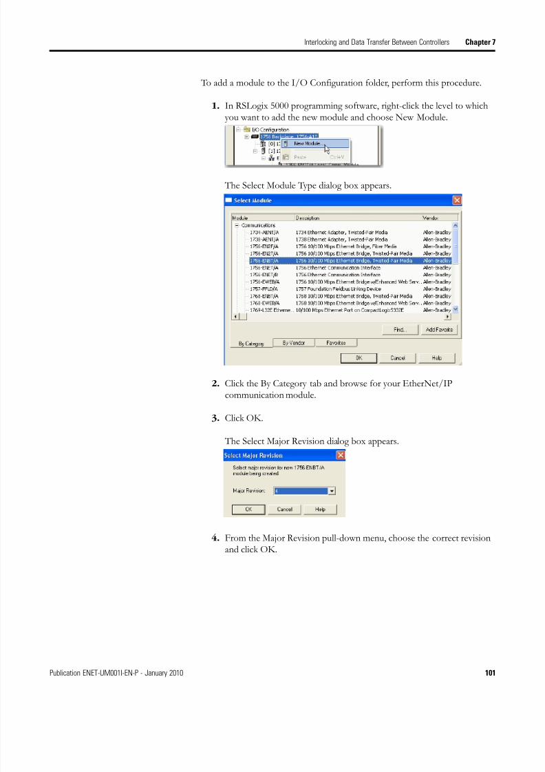
8/13/2019 EtherNet-IP Modules in Logix5000 Control Systems User Manual
http://slidepdf.com/reader/full/ethernet-ip-modules-in-logix5000-control-systems-user-manual 101/230
Publication ENET-UM001I-EN-P - January 2010 101
Interlocking and Data Transfer Between Controllers Chapter 7
To add a module to the I/O Configuration folder, perform this procedure.
1. In RSLogix 5000 programming software, right-click the level to whichyou want to add the new module and choose New Module.
The Select Module Type dialog box appears.
2. Click the By Category tab and browse for your EtherNet/IPcommunication module.
3. Click OK.
The Select Major Revision dialog box appears.
4. From the Major Revision pull-down menu, choose the correct revisionand click OK.

8/13/2019 EtherNet-IP Modules in Logix5000 Control Systems User Manual
http://slidepdf.com/reader/full/ethernet-ip-modules-in-logix5000-control-systems-user-manual 102/230
102 Publication ENET-UM001I-EN-P - January 2010
Chapter 7 Interlocking and Data Transfer Between Controllers
The New Module dialog box appears.
5. Configure your new module.
a. In the Name field, type the name of your module.
b. From the Comm Format pull-down menu, select a communicationformat.
c. In the Slot field, type the chassis slot number.d. In the Chassis Size field, type the chassis size.
e. From the Revision pull-down menu, select a revision number.
f. In the IP Address field, type the module IP address.
g. From the Electronic Keying pull-down menu, select Disable Keying.
6. Click OK.
IMPORTANT When consuming a tag, select None as theCommunication Format.

8/13/2019 EtherNet-IP Modules in Logix5000 Control Systems User Manual
http://slidepdf.com/reader/full/ethernet-ip-modules-in-logix5000-control-systems-user-manual 103/230
Publication ENET-UM001I-EN-P - January 2010 103
Interlocking and Data Transfer Between Controllers Chapter 7
Create the Consumed Tag
To create the consumed tag, perform this procedure.
1. In the consumer controller’s project in RSLogix 5000 programmingsoftware, right-click the Controller Tags folder and choose Edit Tags.
The Controllers Tag dialog box appears.
Only controller-scoped tags can consume data.
2. In the Controller Tags window, right-click the tag that will consume thedata and choose Edit Tag Properties.
The Tag Properties dialog box appears.
3. From the Type pull-down menu, choose Consumed.
4. In the Data Type field, enter a data type that matches the type assignedto the produced tag.

8/13/2019 EtherNet-IP Modules in Logix5000 Control Systems User Manual
http://slidepdf.com/reader/full/ethernet-ip-modules-in-logix5000-control-systems-user-manual 104/230
104 Publication ENET-UM001I-EN-P - January 2010
Chapter 7 Interlocking and Data Transfer Between Controllers
5. Click Connection.
The Consumed Tag Connection dialog box appears.
6. From the Producer pull-down menu, choose the controller that
produces the data.
7. In the Remote Data field, type the tag name or instance number of theproduced data.
8. In the RPI field, type the requested packet interval (RPI) for theconnection.
Only set the RPI to the rate the application requires.
For information on RPI and how it affects the actual packet interval(API), see the EtherNet/IP Performance Application Solution,publication ENET-AP001.
9. Click OK.
IMPORTANT The RPI determines the number of packets per second
that the module will produce on a connection. Eachmodule can only produce a limited number of packetsper second. Exceeding this limit prevents the modulefrom opening more connections.

8/13/2019 EtherNet-IP Modules in Logix5000 Control Systems User Manual
http://slidepdf.com/reader/full/ethernet-ip-modules-in-logix5000-control-systems-user-manual 105/230
Publication ENET-UM001I-EN-P - January 2010 105
Interlocking and Data Transfer Between Controllers Chapter 7
Guidelines for Message(MSG) Instructions
Follow these guidelines.
For more information on programming MSG instructions, see the Logix5000Controller General Instructions Reference Manual, publication 1756-RM003.
The individual system user manuals for Logix5000 controllers also provideMSG examples unique to specific controller platforms.
MSG Instruction Guidelines
Guideline Details
For each MSG instruction, create a control tag. Each MSG instruction requires its own control tag.
· Data type = MESSAGE
· Scope = controller
· The tag cannot be part of an array or a user-defined data type.
Keep the source and destination data at thecontroller scope.
A MSG instruction can access only tags that are in the Controller Tags folder.
If your MSG is to a module that uses 16-bitintegers, use a buffer of INTs in the MSG andDINTs throughout the project.
If your message is to a module that uses 16-bit integers, such as a PLC-5 or SLC 500controller, and it transfers integers (not REALs), use a buffer of INTs in the message andDINTs throughout the project.
This increases the efficiency of your project because Logix5000 controllers executemore efficiently and use less memory when working with 32-bit integers (DINTs).
Cache the connected MSGs that execute mostfrequently.
Cache the connection for those MSG instructions that execute most frequently, up tothe maximum number permissible for your controller revision.
This optimizes execution time because the controller does not have to open aconnection each time the message executes.
If you want to enable more than 16 MSGs atone time, use some type of managementstrategy.
If you enable more than 16 MSGs at one time, some MSG instructions may experiencedelays in entering the queue. To guarantee the execution of each message, either:
· enable each message in sequence.
·
enable the messages in groups.· program a message to communicate with multiple modules.
· program logic to coordinate the execution of messages.
Keep the number of unconnected and uncachedMSGs less than the number of unconnectedbuffers.
The controller can have 10...40 unconnected buffers. The default number is 10.
· If all the unconnected buffers are in use when an instruction leaves the messagequeue, the instruction errors and does not transfer the data.
· You can increase the number of unconnected buffers to a maximum of 40.

8/13/2019 EtherNet-IP Modules in Logix5000 Control Systems User Manual
http://slidepdf.com/reader/full/ethernet-ip-modules-in-logix5000-control-systems-user-manual 106/230
106 Publication ENET-UM001I-EN-P - January 2010
Chapter 7 Interlocking and Data Transfer Between Controllers
Connections for Messages Messages transfer data to other modules, such as other controllers or operatorinterfaces. Each message uses one connection, regardless of how manymodules are in the message path. To conserve connections, you can configureone message to read from or write to multiple modules.
These connected messages can leave the connection open (cache) or close theconnection when the message is done transmitting.
Cache Message Connections
Message Connections
Type of Message Communication Method Used Connection Used
CIP data table read or write CIP Yes
PLC2, PLC3, PLC5, or SLC (alltypes)
CIP No
CIP with Source ID No
DH+ Yes
CIP generic CIPYour choice
(1)
(1) You can connect CIP generic messages, but for most applications we recommend you leave CIP generic
messages unconnected.
Block-transfer read or write Yes
Guidelines for Caching Message Connections
Message Execution Instruction
Repeated Cache the connection.
Important: Caching keeps the connection open and optimizesexecution time. Opening a connection each time the messageexecutes increases execution time.
Infrequent Do not cache the connection.
Important: Not caching closes the connection uponcompletion of the message, freeing up the connection for otheruses.

8/13/2019 EtherNet-IP Modules in Logix5000 Control Systems User Manual
http://slidepdf.com/reader/full/ethernet-ip-modules-in-logix5000-control-systems-user-manual 107/230
Publication ENET-UM001I-EN-P - January 2010 107
Interlocking and Data Transfer Between Controllers Chapter 7
Enter Message Logic To send or receive data from an EtherNet/IP module via a message, you mustprogram a MSG instruction in the local controller’s logic. If the target moduleis configured in the I/O Configuration folder of the controller, browse toselect the module or manually enter the message path in the MSG instruction.
Add the EtherNet/IP Module to the Local Controller’s I/OConfiguration
To use the Browse button to select the target device of a MSG instruction, addthat remote device to the I/O Configuration folder of the local controller. Within the I/O Configuration folder, organize the local and remote devicesinto a hierarchy of tree/branch, parent/child.
For a typical local/remote MSG structure, such as the one shown below,
you build the I/O configuration with the following steps.
1. Add the local communication module for the local controller.
2. Add the remote communication module for the remote controller.
IMPORTANT The number of TCP and CIP connections supported by the1768-ENBT module depends on the firmware revision you areusing. If you are using firmware revision 1.x , the modulesupports 32 TCP connections and 64 CIP connections. If you areusing firmware revision 2.x or later, the module supports 64 TCP
connections and 128 CIP connections.
Local
Communication
Module
Local
Controller
Remote
Controller
Remote
Communication
Module

8/13/2019 EtherNet-IP Modules in Logix5000 Control Systems User Manual
http://slidepdf.com/reader/full/ethernet-ip-modules-in-logix5000-control-systems-user-manual 108/230
108 Publication ENET-UM001I-EN-P - January 2010
Chapter 7 Interlocking and Data Transfer Between Controllers
3. Add the remote controller.
Select a communication format for a communication module based on themodules in its remote chassis.
To add a module to the I/O Configuration folder, perform this procedure.
1. In RSLogix 5000 programming software, right-click the level to whichyou want to add the new module and choose New Module.
Module Communication Formats
If Select a communication format that specifies
The remote chassis contains only analog modules, diagnostic digital modules,fused output modules, or communication modules
None
The remote chassis only contains standard, digital input and output modules(no diagnostic modules or fused output modules)
Rack Optimization
You want to receive I/O module and chassis slot information from arack-optimized remote chassis owned by another controller
Listen-Only Rack Optimization

8/13/2019 EtherNet-IP Modules in Logix5000 Control Systems User Manual
http://slidepdf.com/reader/full/ethernet-ip-modules-in-logix5000-control-systems-user-manual 109/230
Publication ENET-UM001I-EN-P - January 2010 109
Interlocking and Data Transfer Between Controllers Chapter 7
The Select Module Type dialog box appears.
2. Click the By Category tab and browse for your EtherNet/IPcommunication module.
3. Click OK.
The Select Major Revision dialog box appears.
4. From the Major Revision pull-down menu, choose the correct revisionand click OK.
The New Module dialog box appears.

8/13/2019 EtherNet-IP Modules in Logix5000 Control Systems User Manual
http://slidepdf.com/reader/full/ethernet-ip-modules-in-logix5000-control-systems-user-manual 110/230
110 Publication ENET-UM001I-EN-P - January 2010
Chapter 7 Interlocking and Data Transfer Between Controllers
5. Configure your new module.
a. In the Name field, type the name of your module.
b. From the Comm Format pull-down menu, select a communicationformat.
c. In the Slot field, type the chassis slot number.
d. In the Chassis Size field, type the chassis size.
e. From the Revision pull-down menu, select a revision number.
f. In the IP Address field, type the module IP address.
g. From the Electronic Keying pull-down menu, select CompatibleModule.
6. Click OK.
Enter a Message
To enter a message, perform this procedure.
1. Use relay ladder logic to enter a MSG instruction.
2. Click the button to configure the MSG instruction. ...
EXAMPLE Enter a MSG instruction
If count_send = 1 and count_msg.EN = 0 (MSG instruction is not already enabled), then execute a MSG instruction that sends data toanother controller.
count_send
/
count_msg.en
EN
DN
ER
Type - Unconfigured
Message Control count_msg ...
MSG

8/13/2019 EtherNet-IP Modules in Logix5000 Control Systems User Manual
http://slidepdf.com/reader/full/ethernet-ip-modules-in-logix5000-control-systems-user-manual 111/230
Publication ENET-UM001I-EN-P - January 2010 111
Interlocking and Data Transfer Between Controllers Chapter 7
Configure a MSGInstruction
To configure a MSG instruction, perform this procedure.
1. Click in the MSG box.
The Message Configuration dialog box appears.
2. Click the Configuration tab and specify the type of MSG instruction.
Configure a MSG to a Logix5000 Controller
...
If you want to For this item Type or select
Read (receive) the data Message Type CIP Data Table Read
Source Element First element of the tag that contains data in the other controller
Number of Elements Number of elements to transfer
Destination Tag First element of the tag (controller-scoped) in this controller for the data
Write (send) the data Message Type CIP Data Table Write
Source Tag First element of the tag (controller-scoped) in this controller thatcontains the data
Number of Elements Number of elements to transfer
Destination Element First element of the tag for the data in the other controller

8/13/2019 EtherNet-IP Modules in Logix5000 Control Systems User Manual
http://slidepdf.com/reader/full/ethernet-ip-modules-in-logix5000-control-systems-user-manual 112/230
112 Publication ENET-UM001I-EN-P - January 2010
Chapter 7 Interlocking and Data Transfer Between Controllers
Configure a MSG to an SLC 500 Processor
If the data is And you want to For this item Type or select
Integer Read (receive) data Message Type SLC Typed Read
Source Element Data table address in the SLC 500 controller (for example, N7:10)
Number of Elements Number of integers to transfer
Destination Tag First element of int_buffer
Write (send) data Message Type SLC Typed Write
Source Tag First Element of int_buffer
Number of Elements Number of integers to transfer
Destination Element Data table address in the SLC 500 controller (for example, N7:10)
Floating-point (REAL) Read (receive) data Message Type SLC Typed Read
Source Element Data table address in the SLC 500 controller (for example, F8:0)
Number of Elements Number of values to transfer
Destination Tag First element of the tag (controller-scoped) in this controller forthe data
Write (send) data Message Type SLC Typed Write
Source Tag First element of the tag (controller-scoped) in this controller thatcontains the data
Number of Elements Number of values to transfer
Destination Element Data table address in the SLC 500 controller (for example, F8:0)
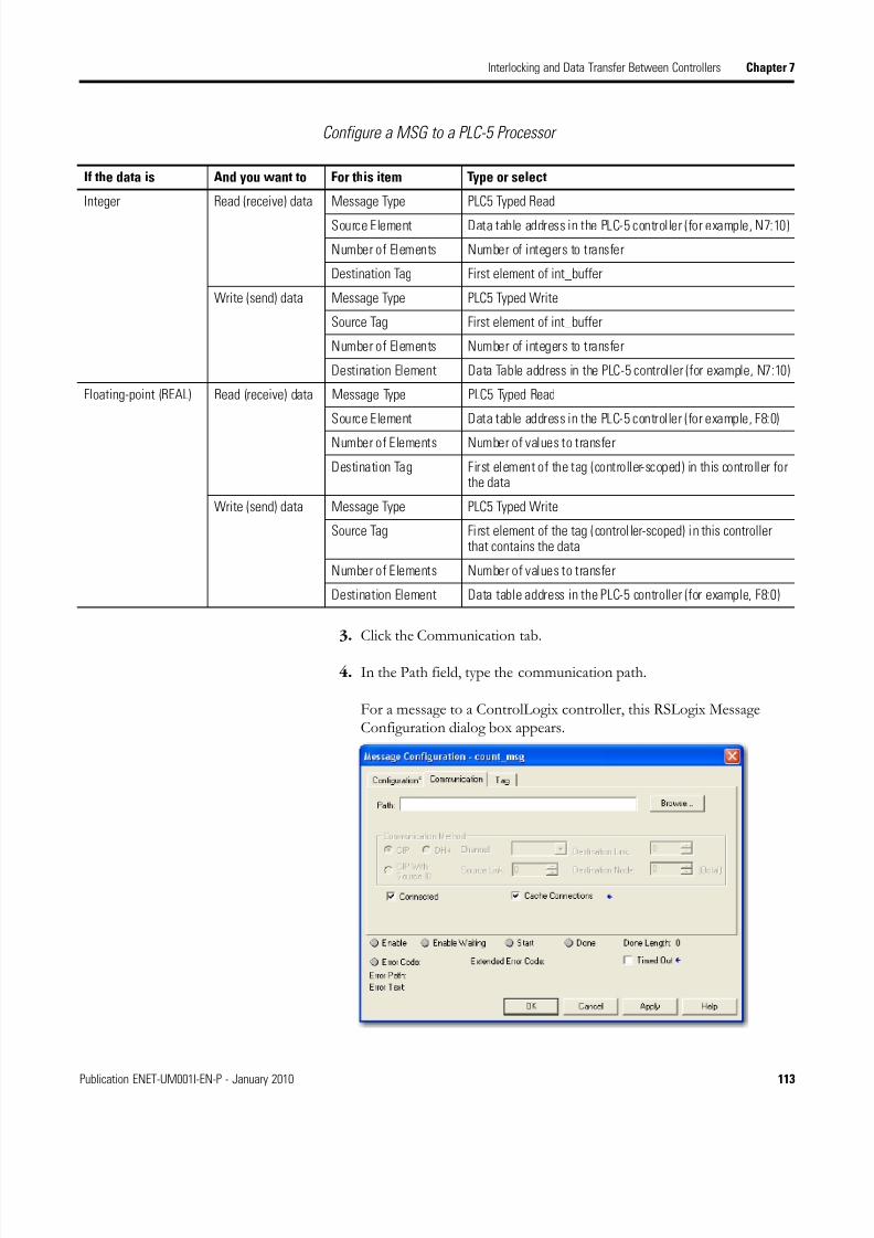
8/13/2019 EtherNet-IP Modules in Logix5000 Control Systems User Manual
http://slidepdf.com/reader/full/ethernet-ip-modules-in-logix5000-control-systems-user-manual 113/230
Publication ENET-UM001I-EN-P - January 2010 113
Interlocking and Data Transfer Between Controllers Chapter 7
Configure a MSG to a PLC-5 Processor
3. Click the Communication tab.
4. In the Path field, type the communication path.
For a message to a ControlLogix controller, this RSLogix MessageConfiguration dialog box appears.
If the data is And you want to For this item Type or select
Integer Read (receive) data Message Type PLC5 Typed Read
Source Element Data table address in the PLC-5 controller (for example, N7:10)
Number of Elements Number of integers to transfer
Destination Tag First element of int_buffer
Write (send) data Message Type PLC5 Typed Write
Source Tag First element of int_buffer
Number of Elements Number of integers to transfer
Destination Element Data Table address in the PLC-5 controller (for example, N7:10)
Floating-point (REAL) Read (receive) data Message Type PLC5 Typed Read
Source Element Data table address in the PLC-5 controller (for example, F8:0)
Number of Elements Number of values to transfer
Destination Tag First element of the tag (controller-scoped) in this controller forthe data
Write (send) data Message Type PLC5 Typed Write
Source Tag First element of the tag (controller-scoped) in this controllerthat contains the data
Number of Elements Number of values to transfer
Destination Element Data table address in the PLC-5 controller (for example, F8:0)

8/13/2019 EtherNet-IP Modules in Logix5000 Control Systems User Manual
http://slidepdf.com/reader/full/ethernet-ip-modules-in-logix5000-control-systems-user-manual 114/230
114 Publication ENET-UM001I-EN-P - January 2010
Chapter 7 Interlocking and Data Transfer Between Controllers
For a message to a SLC 500 or PLC-5 processor, this RSLogix MessageConfiguration dialog box appears.
5. If the target module is configured in the I/O Configuration folder ofthe originating controller, click Browse to select the module or manuallyenter the path to the target module.
A manually entered path begins with the name of the local EtherNet/IPmodule, the port the message exits (2 for EtherNet/IP), and the IPaddress of the next module in the path, which could be the targetmodule.
EXAMPLE Communication path from a Logix5000 controller to a Logix5000 controller overan EtherNet/IP network
washer, 2, 127.127.127.12, 1, 0
Ethernet Network
5
5
5
0
E
N
B
T
5
5
5
0
E
N
B
T
IP Address
127.127.127.12
Message
Where Indicates
Washer Name of the 1756-ENBT, 1756-EN2T, or 1756-EN2F module
2 Ethernet port of the 1756-ENBT, 1756-EN2T, or EN2F module
127.127.127.12 IP address of the 1756-ENBT, 1756-EN2T, or 1756-EN2F module inthe destination chassis
1 Backplane port of the 1756-ENBT, 1756-EN2T, or 1756-EN2Fmodule in the destination chassis
0 Slot number of the destination controller

8/13/2019 EtherNet-IP Modules in Logix5000 Control Systems User Manual
http://slidepdf.com/reader/full/ethernet-ip-modules-in-logix5000-control-systems-user-manual 115/230
Publication ENET-UM001I-EN-P - January 2010 115
Interlocking and Data Transfer Between Controllers Chapter 7
Communicate with PLC-5 orSLC Processors
If the message is to a PLC-5 or SLC 500 processor and it reads or writesintegers (not REALs), use a buffer of INTs in the message. Remember that:
• Logix5000 controllers execute more efficiently and use less memory when working with 32-bit integers (DINTs).
• PLC-5 and SLC 500 processors require 16-bit integers.• Messages require an INT buffer.
• Data can be moved into or out of the buffer as needed.
Converting between INTs and DINTs
If the message is to a device that uses 16-bit integers, such as a PLC-5 or SLC500 controller, and it transfers integers (not REALs), use a buffer of INTs inthe message and DINTs throughout the project. This increases the efficiency
of your project.
1. The Message (MSG) instruction reads 16-bit integers (INTs) from thedevice and stores them in a temporary array of INTs.
2. An File Arith/Logical (FAL) instruction converts the INTs to DINTsfor use by other instructions in your project.
1. An FAL instruction converts the DINTs from the Logix5000 controllerto INTs.
2. The MSG instruction writes the INTs from the temporary array to thedevice.
Read 16-Bit Integers Data From the Device
Buffer of INTs DINTs For Use In the Project
Word 1 INT_Buffer[0] DINT_Array[0]
Word 2 INT_Buffer[1] DINT_Array[1]
Word 3 INT_Buffer[2] DINT_Array[2]
1 2
Write 16-Bit Integers DINTs From theProject
Buffer of INTs Data For theDevice
DINT_Array[0] INT_Buffer[0] Word 1
DINT_Array[1] INT_Buffer[1] Word 2
DINT_Array[2] INT_Buffer[2] Word 3
1 2

8/13/2019 EtherNet-IP Modules in Logix5000 Control Systems User Manual
http://slidepdf.com/reader/full/ethernet-ip-modules-in-logix5000-control-systems-user-manual 116/230
116 Publication ENET-UM001I-EN-P - January 2010
Chapter 7 Interlocking and Data Transfer Between Controllers
Mapping Tags
A Logix5000 controller stores tag names on the controller so that otherdevices can read or write data without having to know physical memory
locations. Many products only understand PLC/SLC data tables, so theLogix5000 controller offers a PLC/SLC mapping function that enables you tomap Logix tag names to memory locations.
• You have to map only the file numbers that are used in messages; theother file numbers do not need to be mapped.
• The mapping table is loaded into the controller and is used whenever alogical address accesses data.
• You can access only controller-scoped tags (global data).
• For each file that is referenced in a PLC-5 or SLC command, make amap entry by:
– typing the PLC/SLC file number of the logical address.
– typing or selecting the Logix5000 controller-scoped (global) tag thatsupplies or receives data for the file number. (You can map multiplefiles to the same tag.)
· For PLC-2 commands, specify the tag that supplies or receives the data.
When mapping tags:
• do not use file numbers 0, 1, and 2. These files are reserved for Output,Input, and Status files in a PLC-5 processor.
• use PLC-5 mapping only for tag arrays of data type INT, DINT, orREAL. Attempting to map elements of system structures may produceundesirable effects.
• use the PLC file identifier of N or B when accessing elements in an INTtag array.

8/13/2019 EtherNet-IP Modules in Logix5000 Control Systems User Manual
http://slidepdf.com/reader/full/ethernet-ip-modules-in-logix5000-control-systems-user-manual 117/230
Publication ENET-UM001I-EN-P - January 2010 117
Interlocking and Data Transfer Between Controllers Chapter 7
This example shows how to use a buffer of INTs.
EXAMPLE Read integers from a PLC-5 controller.
When condition turns on, reads 16-bit integer values (INTs) and stores them in int_buffer. Then the FALinstruction moves the values to dint_array. This converts the values to 32-bit integers (DINTs), for use byother instructions in the ControlLogix controller.
EXAMPLE Write integers to a PLC-5 controller.
When c ondition turns on, moves the values in dint_array to int_buffer. This converts the values to 16-bit
integers (INTs). Then the message instruction sends int_buffer to the other controller.
42424
Where Is an
dint_array Array of DINTs that are used in the ControlLogix controller
int_buffer Array of INTs with the same number of elements asdint_array
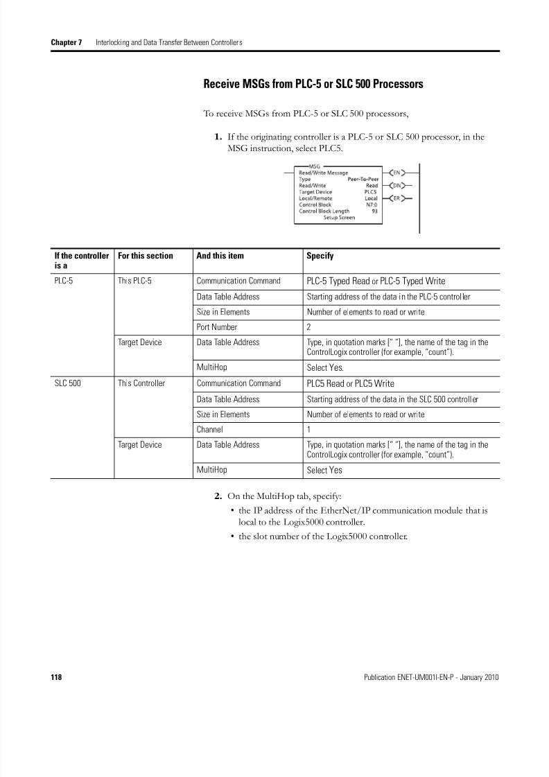
8/13/2019 EtherNet-IP Modules in Logix5000 Control Systems User Manual
http://slidepdf.com/reader/full/ethernet-ip-modules-in-logix5000-control-systems-user-manual 118/230
118 Publication ENET-UM001I-EN-P - January 2010
Chapter 7 Interlocking and Data Transfer Between Controllers
Receive MSGs from PLC-5 or SLC 500 Processors
To receive MSGs from PLC-5 or SLC 500 processors,
1. If the originating controller is a PLC-5 or SLC 500 processor, in theMSG instruction, select PLC5.
2. On the MultiHop tab, specify:
• the IP address of the EtherNet/IP communication module that islocal to the Logix5000 controller.
• the slot number of the Logix5000 controller.
If the controlleris a
For this section And this item Specify
PLC-5 This PLC-5 Communication Command PLC-5 Typed Read or PLC-5 Typed Write
Data Table Address Starting address of the data in the PLC-5 controller
Size in Elements Number of elements to read or write
Port Number 2
Target Device Data Table Address Type, in quotation marks [“ “], the name of the tag in theControlLogix controller (for example, “count”).
MultiHop Select Yes.
SLC 500 This Controller Communication Command PLC5 Read or PLC5 Write
Data Table Address Starting address of the data in the SLC 500 controller
Size in Elements Number of elements to read or write
Channel 1
Target Device Data Table Address Type, in quotation marks [“ “], the name of the tag in theControlLogix controller (for example, “count”).
MultiHop Select Yes

8/13/2019 EtherNet-IP Modules in Logix5000 Control Systems User Manual
http://slidepdf.com/reader/full/ethernet-ip-modules-in-logix5000-control-systems-user-manual 119/230
119Publication ENET-UM001I-EN-P - January 2010 119
Chapter 8
Send Email
Introduction This chapter describes how to send an email through an EtherNet/IP module.
For email, the EtherNet/IP module can be remote or local to the controller.
EtherNet/IP Module as anEmail Client
The EtherNet/IP module is an email client that uses a mail relay server to
send email.
Topic Page
EtherNet/IP Module as an Email Client 119
Send Email Via a Controller-initiated Message Instruction 121
Create String Tags 121
Enter the Ladder Logic 125
Configure the MSG Instruction That Identifies the Mail Relay Server 125
Configure the MSG Instruction That Contains the Email Text 127
Enter Email Text 129
Possible Email Status Codes 129
IMPORTANT The EtherNet/IP module can send an email to only one recipientat a time. It cannot mail to a distribution list.
Ethernet Email
If you want to Then
Send an email to specific personnel when a controller applicationgenerates an alarm or reaches a certain condition
Program the controller to send a MSG instruction to the EtherNet/IPmodule
The MSG instruction then instructs the EtherNet/IP module to sendthe email text (contained within the MSG instruction) to the mailrelay server.
Multiple controllers can use the same EtherNet/IP module toinitiate email.
Send controller or application status information on a regular basisto a project manager
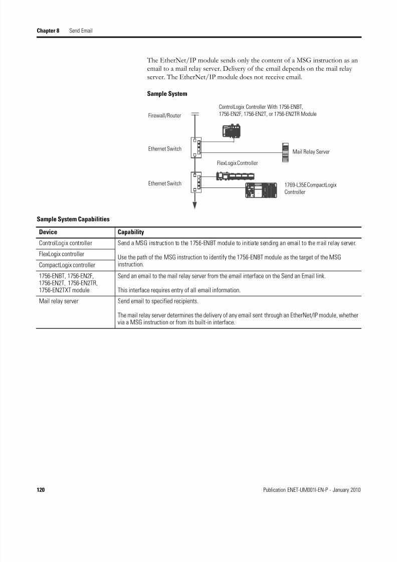
8/13/2019 EtherNet-IP Modules in Logix5000 Control Systems User Manual
http://slidepdf.com/reader/full/ethernet-ip-modules-in-logix5000-control-systems-user-manual 120/230
120 Publication ENET-UM001I-EN-P - January 2010
Chapter 8 Send Email
The EtherNet/IP module sends only the content of a MSG instruction as anemail to a mail relay server. Delivery of the email depends on the mail relayserver. The EtherNet/IP module does not receive email.
Sample System
Firewall/Router
ControlLogix Controller With 1756-ENBT,
1756-EN2F, 1756-EN2T, or 1756-EN2TR Module
Ethernet Switch
Ethernet Switch
FlexLogix Controller
1769-L35E CompactLogix
Controller
Mail Relay Server
Sample System Capabilities
Device Capability
ControlLogix controller Send a MSG instruction to the 1756-ENBT module to initiate sending an email to the mail relay server.
Use the path of the MSG instruction to identify the 1756-ENBT module as the target of the MSGinstruction.
FlexLogix controller
CompactLogix controller
1756-ENBT, 1756-EN2F,1756-EN2T, 1756-EN2TR,1756-EN2TXT module
Send an email to the mail relay server from the email interface on the Send an Email link.
This interface requires entry of all email information.
Mail relay server Send email to specified recipients.
The mail relay server determines the delivery of any email sent through an EtherNet/IP module, whethervia a MSG instruction or from its built-in interface.
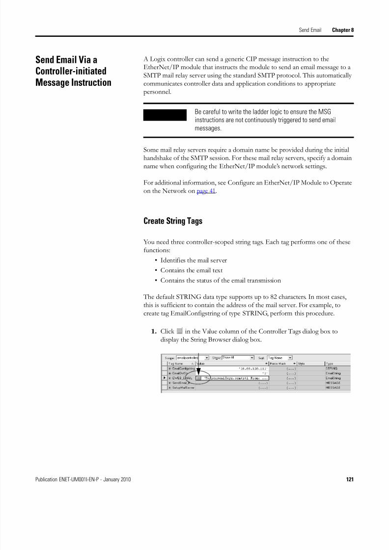
8/13/2019 EtherNet-IP Modules in Logix5000 Control Systems User Manual
http://slidepdf.com/reader/full/ethernet-ip-modules-in-logix5000-control-systems-user-manual 121/230
Publication ENET-UM001I-EN-P - January 2010 121
Send Email Chapter 8
Send Email Via aController-initiatedMessage Instruction
A Logix controller can send a generic CIP message instruction to theEtherNet/IP module that instructs the module to send an email message to aSMTP mail relay server using the standard SMTP protocol. This automaticallycommunicates controller data and application conditions to appropriatepersonnel.
Some mail relay servers require a domain name be provided during the initialhandshake of the SMTP session. For these mail relay servers, specify a domainname when configuring the EtherNet/IP module’s network settings.
For additional information, see Configure an EtherNet/IP Module to Operate
on the Network on page 41.
Create String Tags
You need three controller-scoped string tags. Each tag performs one of thesefunctions:
• Identifies the mail server
• Contains the email text
• Contains the status of the email transmission
The default STRING data type supports up to 82 characters. In most cases,this is sufficient to contain the address of the mail server. For example, tocreate tag EmailConfigstring of type STRING, perform this procedure.
1. Click in the Value column of the Controller Tags dialog box todisplay the String Browser dialog box.
IMPORTANT Be careful to write the ladder logic to ensure the MSGinstructions are not continuously triggered to send emailmessages.
...

8/13/2019 EtherNet-IP Modules in Logix5000 Control Systems User Manual
http://slidepdf.com/reader/full/ethernet-ip-modules-in-logix5000-control-systems-user-manual 122/230
122 Publication ENET-UM001I-EN-P - January 2010
Chapter 8 Send Email
The String Browser dialog box appears.
2. Enter the IP address or host name of the mail server.
3. Click OK.
The tags for the email text and transmission status can contain up to 474characters. For these tags, you must create a user-defined STRING datatype. The default STRING data type in RSLogix 5000 programmingsoftware is not large enough for most email text.
To create a user-defined STRING data type, perform this procedure.
1. In the Data Types folder in RSLogix 5000 programming software,navigate to the Strings folder and double-click a String data type.
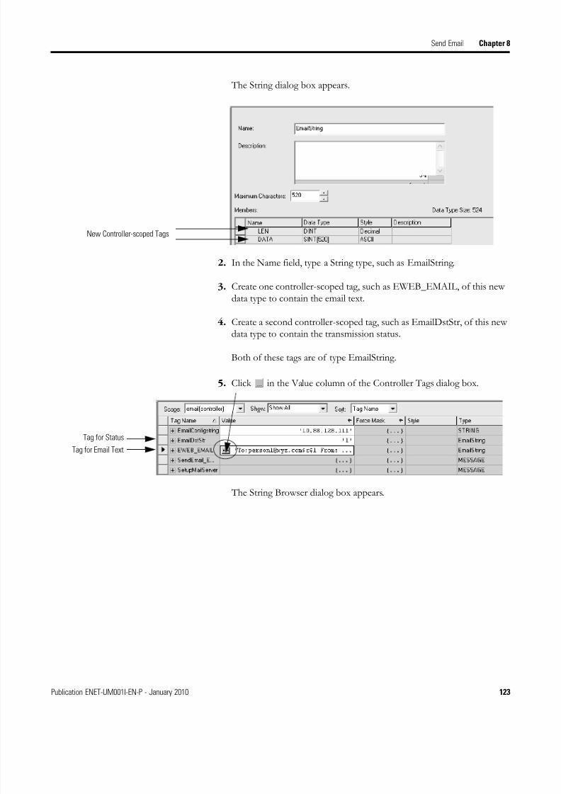
8/13/2019 EtherNet-IP Modules in Logix5000 Control Systems User Manual
http://slidepdf.com/reader/full/ethernet-ip-modules-in-logix5000-control-systems-user-manual 123/230
Publication ENET-UM001I-EN-P - January 2010 123
Send Email Chapter 8
The String dialog box appears.
2. In the Name field, type a String type, such as EmailString.
3. Create one controller-scoped tag, such as EWEB_EMAIL, of this newdata type to contain the email text.
4. Create a second controller-scoped tag, such as EmailDstStr, of this newdata type to contain the transmission status.
Both of these tags are of type EmailString.
5. Click in the Value column of the Controller Tags dialog box.
The String Browser dialog box appears.
New Controller-scoped Tags
...
Tag for Email Text
Tag for Status
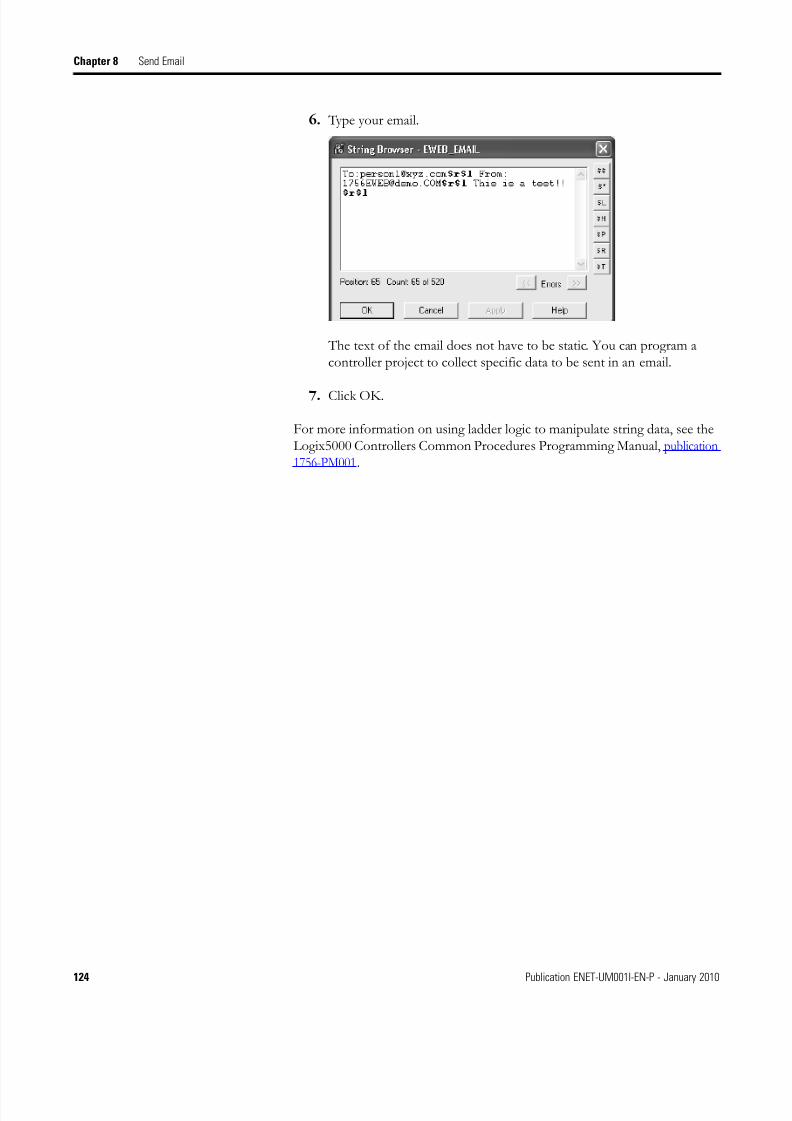
8/13/2019 EtherNet-IP Modules in Logix5000 Control Systems User Manual
http://slidepdf.com/reader/full/ethernet-ip-modules-in-logix5000-control-systems-user-manual 124/230
124 Publication ENET-UM001I-EN-P - January 2010
Chapter 8 Send Email
6. Type your email.
The text of the email does not have to be static. You can program acontroller project to collect specific data to be sent in an email.
7. Click OK.
For more information on using ladder logic to manipulate string data, see theLogix5000 Controllers Common Procedures Programming Manual, publication1756-PM001.

8/13/2019 EtherNet-IP Modules in Logix5000 Control Systems User Manual
http://slidepdf.com/reader/full/ethernet-ip-modules-in-logix5000-control-systems-user-manual 125/230
Publication ENET-UM001I-EN-P - January 2010 125
Send Email Chapter 8
Enter the Ladder Logic
Ladder logic requires two MSG instructions. One MSG instruction configuresthe mail server and needs to be executed only once. The second MSG
instruction triggers the email. Execute this email MSG instruction as often asneeded.
The first rung configures the mail server. The second rung sends the emailtext.
Configure the MSG Instruction That Identifies the Mail RelayServer
To configure the MSG instruction that identifies the mail relay server, perform
this procedure.
1. In the MSG instruction, click the Communication tab.

8/13/2019 EtherNet-IP Modules in Logix5000 Control Systems User Manual
http://slidepdf.com/reader/full/ethernet-ip-modules-in-logix5000-control-systems-user-manual 126/230
126 Publication ENET-UM001I-EN-P - January 2010
Chapter 8 Send Email
2. In the Path field, type the path for the MSG instruction.
The path starts with the controller initiating the MSG instruction.
a. Enter the number of the port from which the message exits and theaddress of the next module in the path.
For example, if the EtherNet/IP module is in the same chassis as thecontroller and is in slot 2, the path is: 1, 2.
For more information on configuring the path of a MSG instruction,see the Logix5000 Controllers General Instructions Reference Manual,publication 1756-RM003.
3. Click the Configuration tab.
4. Configure the MSG parameters for sending an email.
a. From the Service Type pull-down menu, choose Attribute Single
b. In the Instance field, type 1.
c. In the Class field, type 32f.
d. In the Attribute field, type 5.
e. From the Source Element pull-down menu, choose the tag thatcontains your email text.
f. In the Source Length field, type the number of characters in the emailplus four.
In this example, you would enter 13 for the number of charactersplus 4 for a total of 17.
After the MSG instruction that configures the mail relay server executessuccessfully, the controller stores the mail relay server information innonvolatile memory. The controller retains this information, eventhrough power cycles, until another MSG instruction changes theinformation.
The Source Length is the number of characters in the
STRING tag that identifies the mail relay server plus 4
characters.
In this example, the tag contains 13 characters.

8/13/2019 EtherNet-IP Modules in Logix5000 Control Systems User Manual
http://slidepdf.com/reader/full/ethernet-ip-modules-in-logix5000-control-systems-user-manual 127/230
Publication ENET-UM001I-EN-P - January 2010 127
Send Email Chapter 8
Configure the MSG Instruction That Contains the Email Text
To configure the MSG instruction that contains the email text, perform thisprocedure.
1. Click the Configuration tab.
The Source Length is the number of characters in the email tag plus 4characters.
In this example, the email text contains 65 characters.
2. Configure the MSG parameters for sending an email.
a. From the Service Type pull-down menu, choose Custom.
b. In the Service Code field, type 4b.
c. In the Instance field, type 1.
d. In the Class field, type 32f.
e. In the Attribute field, type 0.
f. From the Source Element pull-down menu, choose the tag thatcontains your email text.
g. In the Source Length field, type the number of characters in the emailplus four.
In this example, you would enter 65 for the number of charactersplus 4 for a total of 69.
h. From the Destination pull-down menu, choose a tag to contain thestatus of your email transmission.

8/13/2019 EtherNet-IP Modules in Logix5000 Control Systems User Manual
http://slidepdf.com/reader/full/ethernet-ip-modules-in-logix5000-control-systems-user-manual 128/230
128 Publication ENET-UM001I-EN-P - January 2010
Chapter 8 Send Email
3. Click the Communication tab.
4. In the Path field, type the path from the controller to the EtherNet/IPmodule.
The path starts with the controller initiating the MSG instruction. Thesecond number in the path represents the port from which the messageexits and the address of the next module in the path.
For example, if the EtherNet/IP module is in the same chassis as thecontroller and is in slot 2, the path is: 1, 2.
5. If all the devices in the path are configured in the initiating controller’sI/O Configuration tree, click Browse to select the target module.
The software automatically fills in the path.
6. Click OK.
For more information on configuring the path of an MSG instruction, see theLogix5000 Controllers General Instructions Reference Manual, publication1756-RM003.

8/13/2019 EtherNet-IP Modules in Logix5000 Control Systems User Manual
http://slidepdf.com/reader/full/ethernet-ip-modules-in-logix5000-control-systems-user-manual 129/230
Publication ENET-UM001I-EN-P - January 2010 129
Send Email Chapter 8
Enter Email Text Use the string browser to enter the text of the email. To include To:, From:,and Subject: fields in the email, use <CR><LF> symbols to separate each ofthese fields. The To: and From fields are required; the Subject: field is optional.For example:
To: email address of recipient <CR><LF> From: email address of sender <CR><LF> Subject: subject of message <CR><LF> body of email message
An email message must not exceed 474 characters in length. An additional4-byte string-length value is added to the tag. As a result, the maximum sourcelength is 478 characters.
Possible Email StatusCodes
Examine the destination element of the email MSG to see whether the email was successfully delivered to the mail relay server. A successful deliveryindicates that the mail relay server placed the email message in a queue fordelivery, but it does not mean the intended recipient received the emailmessage. These are the possible codes that a destination element couldcontain.
Email Status Code Descriptions
ErrorCode(Hex)
Extended-errorCode(Hex)
Description
0x00 None Delivery successful to the mail relay server.
0x02 None Resource unavailable. The email object was unable to obtain memory resources to initiate the SMTP session.
0x08 None Unsupported Service Request. Make sure the service code is 0x4B and the Class is 0x32F.
0x11 None Reply data too large. The Destination string must reserve space for the SMTP server reply message. The maximumreply can be 470 bytes.
0x13 None Configuration data size too short. The Source Length is less than the Source Element string size plus the 4-byte length.The Source Length must equal the Source Element string size + 4.
0x15 None Configuration data size too large. The Source Length is greater than the Source Element string size plus the 4-bytelength. The Source Length must equal the Source Element string size + 4.
0x19 None Data write failure. An error occurred when attempting to write the SMTP server address (attribute 4) to non-volatilememory.
0xFF 0x0100 Error returned by email server; check the Destination string for reason. The email message was not queued fordelivery.
0x0101 SMTP mail server not configured. Attribute 5 was not set with a SMTP server address.
0x0102 “To:” address not specified. Attribute 1 was not set with a “To:” address AND there is not a “To:” field header in theemail body.
0x0103 “From:” address not specified. Attribute 2 was not set with a “From:” address AND there is not a “From:” field headerin the email body.

8/13/2019 EtherNet-IP Modules in Logix5000 Control Systems User Manual
http://slidepdf.com/reader/full/ethernet-ip-modules-in-logix5000-control-systems-user-manual 130/230
130 Publication ENET-UM001I-EN-P - January 2010
Chapter 8 Send Email
0xFF 0x0104 Unable to connect to SMTP mail server set in Attribute 5. If the mail server address is a host name, make sure that thedevice supports DNS, and that a Name Server is configured. If the hostname is not fully qualified, for example,“mailhost” and not “mailhost.xx.yy.com” then the domain must be configured as “xx.yy.com”. Try “ping <mail serveraddress>” to insure the mail server is reachable from your network. Also try “telnet <mail server address> 25” whichattempts to initiate a SMTP session with the mail server via telnet over port 25. (If you connect then enter “QUIT”).
0x0105 Communication error with SMTP mail server. An error occurred after the initial connection with the SMTP mail server.
See the ASCII text following the error code for more details as to the type of error.
0x0106 SMTP mail server host name DNS query did not complete. A previous send service request with a host name as theSMTP mail server address did not yet complete. Note that a timeout for a DNS lookup with an invalid host name cantake up to 3 minutes. Long timeouts can also occur if a domain name or name server is not configured correctly.
Email Status Code Descriptions
ErrorCode(Hex)
Extended-errorCode(Hex)
Description

8/13/2019 EtherNet-IP Modules in Logix5000 Control Systems User Manual
http://slidepdf.com/reader/full/ethernet-ip-modules-in-logix5000-control-systems-user-manual 131/230
131Publication ENET-UM001I-EN-P - January 2010 131
Chapter 9
Communicate with PanelView Terminals
Introduction This chapter describes how a controller uses an EtherNet/IP communicationmodule to communicate with PanelView and PanelView Plus terminals over
an EtherNet/IP network.
Set Up the Hardware In this example, the controller in the local chassis shares data with an HMIapplication on the EtherNet/IP network. This application could be running a:
• PanelView terminal.
• PanelView Plus terminal.
• workstation running RSView 32 software.
• workstation running an RSView Enterprise application, such as RSView
Machine Edition or RSView Supervisory Edition.
Ethernet Communication with Panelview
Topic Page
Set Up the Hardware 131
Connections to PanelView Terminals 132
Add a PanelView Terminal 133
Organize Controller Data for a PanelView Terminal 136Connections to RSView Applications 136
A CData
B
Item Description
A Local chassis containing a Logix5000 controller and EtherNet/IP connection
B Switch
C HMI device with EtherNet/IP connectivity
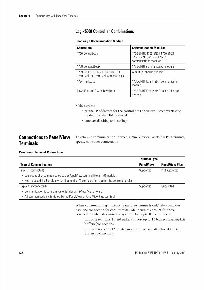
8/13/2019 EtherNet-IP Modules in Logix5000 Control Systems User Manual
http://slidepdf.com/reader/full/ethernet-ip-modules-in-logix5000-control-systems-user-manual 132/230
132 Publication ENET-UM001I-EN-P - January 2010
Chapter 9 Communicate with PanelView Terminals
Logix5000 Controller Combinations
Make sure to:
· set the IP addresses for the controller’s EtherNet/IP communicationmodule and the HMI terminal.
· connect all wiring and cabling.
Connections to PanelViewTerminals
To establish communication between a PanelView or PanelView Plus terminal,
specify controller connections.
When communicating implicitly (PanelView terminals only), the controlleruses one connection for each terminal. Make sure to account for theseconnections when designing the system. The Logix5000 controllers:
· firmware revisions 11 and earlier support up to 16 bidirectional implicitbuffers (connections).
· firmware revisions 12 or later support up to 32 bidirectional implicitbuffers (connections).
Choosing a Communication Module
Controllers Communication Modules
1756 ControlLogix 1756-ENBT, 1756-EN2F, 1756-EN2T,1756-EN2TR, or 1756-EN2TXTcommunication modules
1768 CompactLogix 1768-ENBT communication module
1769-L23E-Q1B, 1769-L23E-QBFC1B,1769-L32E, or 1769-L35E CompactLogix
A built-in EtherNet/IP port
1794 FlexLogix 1788-ENBT EtherNet/IP communicationmodule
PowerFlex 700S with DriveLogix 1788-ENBT EtherNet/IP communicationmodule
PanelView Terminal Connections
Type of Communication
Terminal Type
PanelView PanelView Plus
Implicit (connected)
• Logix controller communicates to the PanelView terminal like an I/O module.
• You must add the PanelView terminal to the I/O configuration tree for the controller project.
Supported Not supported
Explicit (unconnected)
• Communication is set up in PanelBuilder or RSView ME software.
• All communication is initiated by the PanelView or PanelView Plus terminal.
Supported Supported
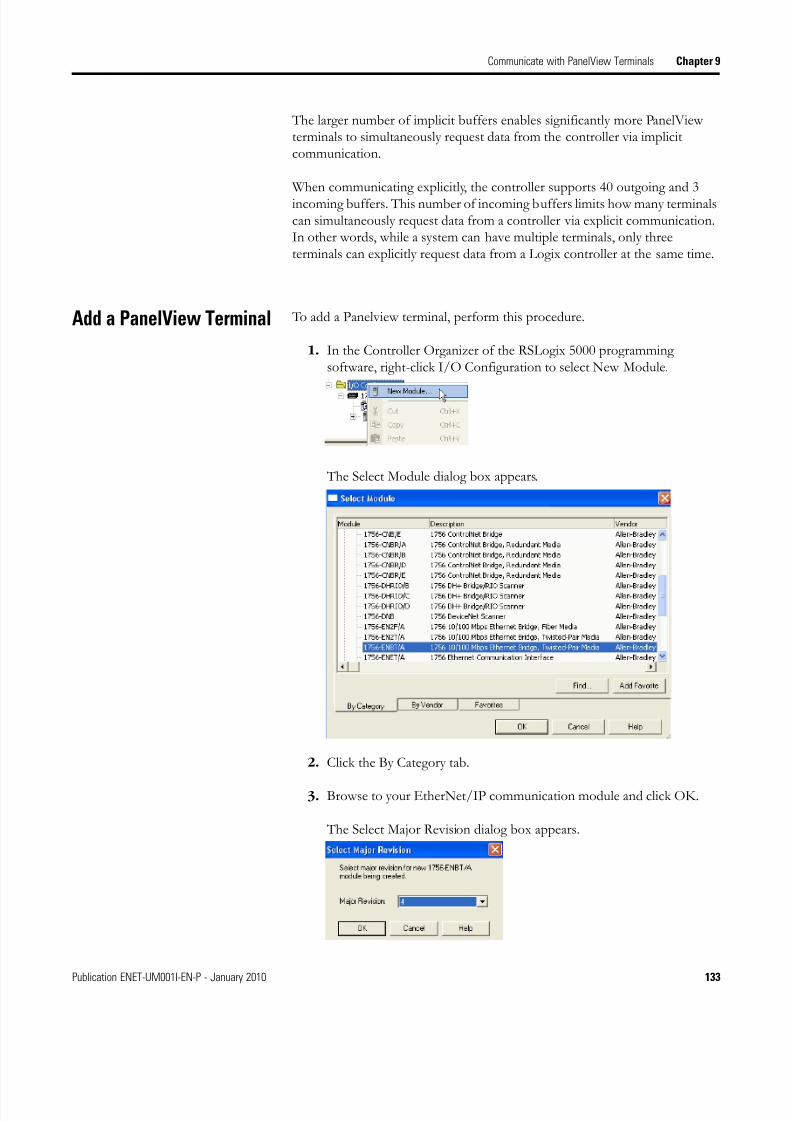
8/13/2019 EtherNet-IP Modules in Logix5000 Control Systems User Manual
http://slidepdf.com/reader/full/ethernet-ip-modules-in-logix5000-control-systems-user-manual 133/230
Publication ENET-UM001I-EN-P - January 2010 133
Communicate with PanelView Terminals Chapter 9
The larger number of implicit buffers enables significantly more PanelViewterminals to simultaneously request data from the controller via implicitcommunication.
When communicating explicitly, the controller supports 40 outgoing and 3incoming buffers. This number of incoming buffers limits how many terminalscan simultaneously request data from a controller via explicit communication.In other words, while a system can have multiple terminals, only threeterminals can explicitly request data from a Logix controller at the same time.
Add a PanelView Terminal To add a Panelview terminal, perform this procedure.
1. In the Controller Organizer of the RSLogix 5000 programmingsoftware, right-click I/O Configuration to select New Module.
The Select Module dialog box appears.
2. Click the By Category tab.
3. Browse to your EtherNet/IP communication module and click OK.
The Select Major Revision dialog box appears.
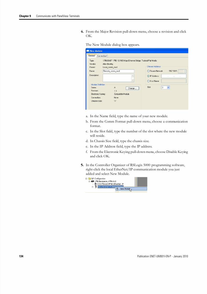
8/13/2019 EtherNet-IP Modules in Logix5000 Control Systems User Manual
http://slidepdf.com/reader/full/ethernet-ip-modules-in-logix5000-control-systems-user-manual 134/230
134 Publication ENET-UM001I-EN-P - January 2010
Chapter 9 Communicate with PanelView Terminals
4. From the Major Revision pull-down menu, choose a revision and clickOK.
The New Module dialog box appears.
a. In the Name field, type the name of your new module.
b. From the Comm Format pull-down menu, choose a communicationformat.
c. In the Slot field, type the number of the slot where the new module will reside.
d. In Chassis Size field, type the chassis size.
e. In the IP Address field, type the IP address.
f. From the Electronic Keying pull-down menu, choose Disable Keyingand click OK.
5. In the Controller Organizer of RSLogix 5000 programming software,right-click the local EtherNet/IP communication module you justadded and select New Module.
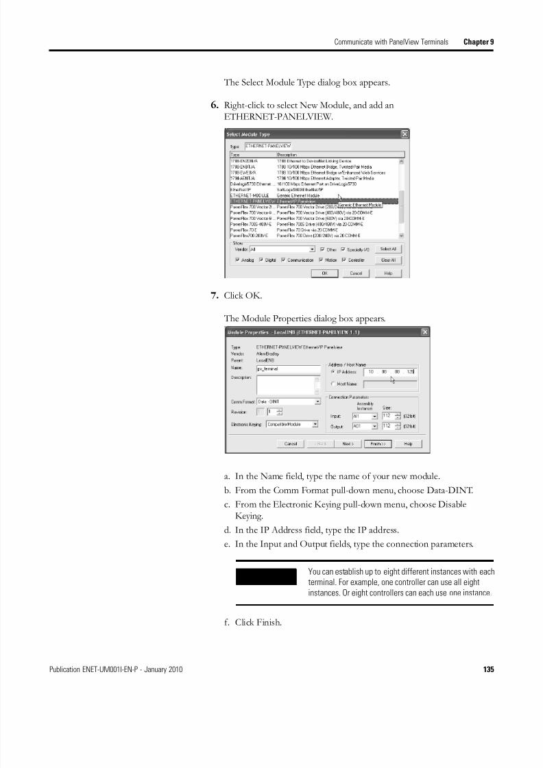
8/13/2019 EtherNet-IP Modules in Logix5000 Control Systems User Manual
http://slidepdf.com/reader/full/ethernet-ip-modules-in-logix5000-control-systems-user-manual 135/230
Publication ENET-UM001I-EN-P - January 2010 135
Communicate with PanelView Terminals Chapter 9
The Select Module Type dialog box appears.
6. Right-click to select New Module, and add anETHERNET-PANELVIEW.
7. Click OK.
The Module Properties dialog box appears.
a. In the Name field, type the name of your new module.
b. From the Comm Format pull-down menu, choose Data-DINT.
c. From the Electronic Keying pull-down menu, choose DisableKeying.
d. In the IP Address field, type the IP address.
e. In the Input and Output fields, type the connection parameters.
f. Click Finish.
IMPORTANTYou can establish up to eight different instances with each
terminal. For example, one controller can use all eight
instances. Or eight controllers can each use one instance.
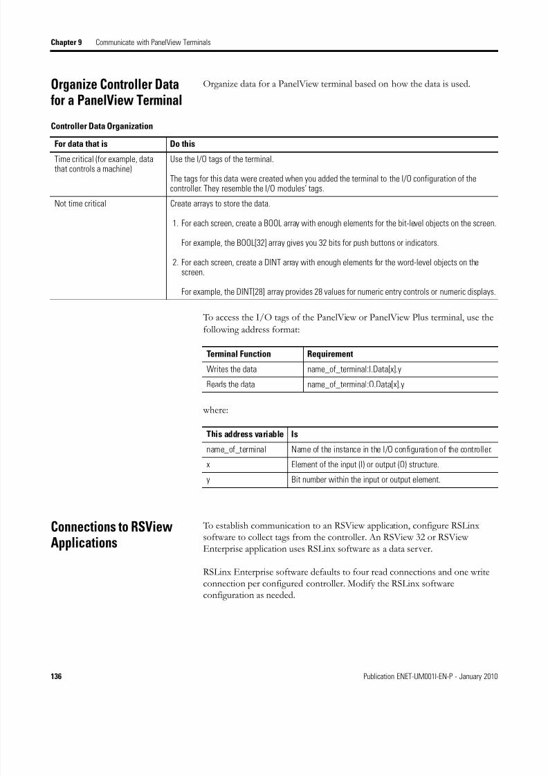
8/13/2019 EtherNet-IP Modules in Logix5000 Control Systems User Manual
http://slidepdf.com/reader/full/ethernet-ip-modules-in-logix5000-control-systems-user-manual 136/230
136 Publication ENET-UM001I-EN-P - January 2010
Chapter 9 Communicate with PanelView Terminals
Organize Controller Datafor a PanelView Terminal
Organize data for a PanelView terminal based on how the data is used.
To access the I/O tags of the PanelView or PanelView Plus terminal, use the
following address format:
where:
Connections to RSView
Applications
To establish communication to an RSView application, configure RSLinxsoftware to collect tags from the controller. An RSView 32 or RSViewEnterprise application uses RSLinx software as a data server.
RSLinx Enterprise software defaults to four read connections and one writeconnection per configured controller. Modify the RSLinx softwareconfiguration as needed.
Controller Data Organization
For data that is Do this
Time critical (for example, datathat controls a machine)
Use the I/O tags of the terminal.
The tags for this data were created when you added the terminal to the I/O configuration of thecontroller. They resemble the I/O modules’ tags.
Not time critical Create arrays to store the data.
1. For each screen, create a BOOL array with enough elements for the bit-level objects on the screen.
For example, the BOOL[32] array gives you 32 bits for push buttons or indicators.
2. For each screen, create a DINT array with enough elements for the word-level objects on the
screen.
For example, the DINT[28] array provides 28 values for numeric entry controls or numeric displays.
Terminal Function Requirement
Writes the data name_of_terminal:I.Data[x].y
Reads the data name_of_terminal:O.Data[x].y
This address variable Is
name_of_terminal Name of the instance in the I/O configuration of the controller.
x Element of the input (I) or output (O) structure.
y Bit number within the input or output element.

8/13/2019 EtherNet-IP Modules in Logix5000 Control Systems User Manual
http://slidepdf.com/reader/full/ethernet-ip-modules-in-logix5000-control-systems-user-manual 137/230
137Publication ENET-UM001I-EN-P - January 2010 137
Chapter 10
Monitor Diagnostics
Introduction The EtherNet/IP communication modules provide several web diagnosticpages. This chapter illustrates each of these web diagnostic pages and definesthe terms presented on each screen.
Topic Page
Diagnostic Web Pages 138
Network Settings 141
Explicit Message Connections 142
I/O Connections 143Ethernet Statistics 144
IMPORTANT To access any of these diagnostic web pages and troubleshootproblems which you may be able to diagnose via one of theseweb diagnostic pages, see Troubleshoot an EtherNet/IP Moduleon page 147.
A 1783-ETAP tap using firmware revision 1.1 does not supportdiagnostic web pages. You must upgrade the tap to firmwarerevision 2.x or later to use diagnostic web pages.

8/13/2019 EtherNet-IP Modules in Logix5000 Control Systems User Manual
http://slidepdf.com/reader/full/ethernet-ip-modules-in-logix5000-control-systems-user-manual 138/230
138 Publication ENET-UM001I-EN-P - January 2010
Chapter 10 Monitor Diagnostics
Diagnostic Web Pages The Diagnostic Overview web page presents a summary of the currentconfiguration and overall status of the module.
Diagnostic Overview Web Page
This field Specifies
Ethernet Link
Speed Whether the Ethernet port is operating at 10 Mbps or 100 Mbps.
Duplex Whether the Ethernet port is operating at half duplex or full duplex.
Autonegotiate Status Whether the port speed and duplex mode were determined via autonegotiation or manualconfiguration.
System Resource Utilization
CPU Current percent CPU utilization for the module.
Web Server
Server Errors Number of requests to the module with an invalid URL.

8/13/2019 EtherNet-IP Modules in Logix5000 Control Systems User Manual
http://slidepdf.com/reader/full/ethernet-ip-modules-in-logix5000-control-systems-user-manual 139/230
Publication ENET-UM001I-EN-P - January 2010 139
Monitor Diagnostics Chapter 10
Redirects Number of requests for a Web page that were redirected by the module (for example, requesting“/” is redirected to “/index.html”).
Timeouts Number of times a connection timeout occurred while processing a Web page.
Access Violations Number of times a page has been requested for which the user has insufficient privilege.
Page Hits Number of times a Web page was successfully accessed.
Form Hits Number of times a Web page form was accessed.
Total Hits Total number of Web page access attempts.
CIP Connection Statistics
Current CIP MSG Connections Current number of CIP connections for message.
CIP MSG Connection Limit Maximum number of CIP connections for messages allowed.
Max MSG Connections Observed Maximum observed number of CIP connections for messages.
Current CIP I/O Connections Current number of CIP connections for I/O.
CIP I/O Connection Limit Maximum number of CIP connections allowed for I/O.
Max I/O Connections Observed Maximum observed number of CIP connections for I/O.
Conn Opens Number of CIP connection open requests.
Open Errors Number of CIP connection open request errors.
Conn Closes Number of CIP connection close requests.
Close Errors Number of CIP connection close request errors.
Conn Timeouts Number of CIP connection timeouts.
TCP Connections (CIP)
Current TCP Connections Current number of active TCP connections for CIP messaging.
TCP Connection Limit Maximum number of TCP connections for CIP messaging allowed.
Maximum Observed Maximum observed number of TCP connections for CIP messaging.
CIP Messaging Statistics
Messages Sent Number of CIP connected messages (packets) sent.
Messages Received Number of CIP connected messages (packets) received.
UCMM Sent Number of CIP unconnected messages (packets) sent.
UCMM Received Number of CIP unconnected messages (packets) received.
I/O Packet / Second Statistics
Total Total number of Class 1 UDP packets the module transmitted and received in the last one-secondsnapshot.
The Total is the sum of the Sent, Received, Inhibited, and Rejected numbers.
Sent Number of Class 1 UDP packets the module transmitted in the last one-second snapshot.
Received Number of Class 1 UDP packets the module received in the last one-second snapshot.
Inhibited Number of Class 1 UDP packets the module inhibited in the last one-second snapshot.
Packets are inhibited if a COS module produces packets faster than 25% of the connection’s RPI.
Diagnostic Overview Web Page
This field Specifies
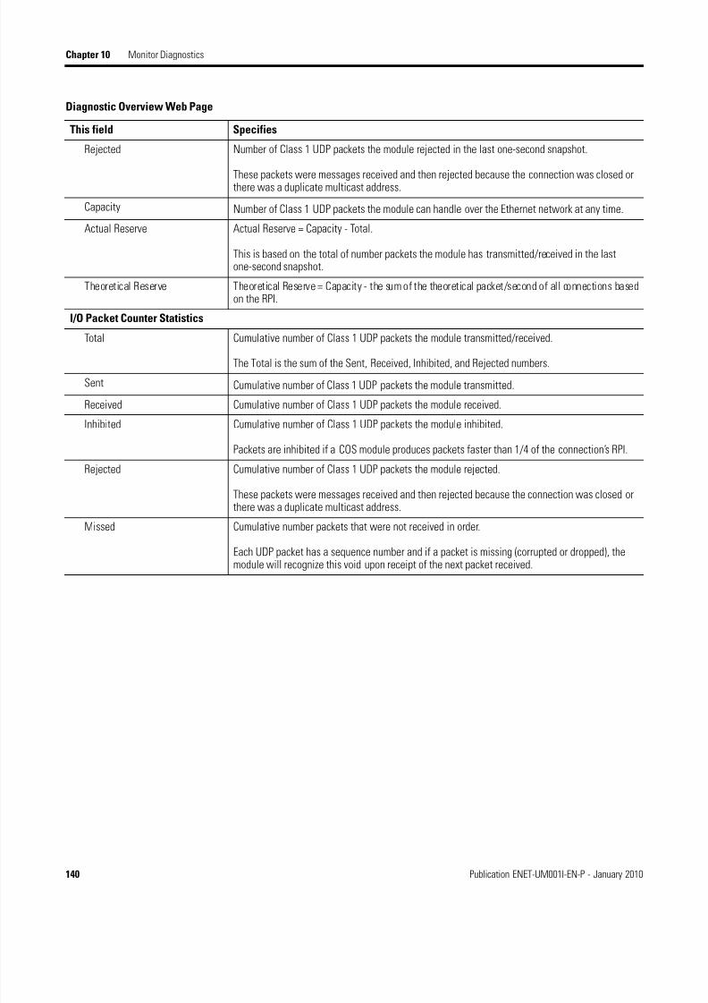
8/13/2019 EtherNet-IP Modules in Logix5000 Control Systems User Manual
http://slidepdf.com/reader/full/ethernet-ip-modules-in-logix5000-control-systems-user-manual 140/230
140 Publication ENET-UM001I-EN-P - January 2010
Chapter 10 Monitor Diagnostics
Rejected Number of Class 1 UDP packets the module rejected in the last one-second snapshot.
These packets were messages received and then rejected because the connection was closed orthere was a duplicate multicast address.
Capacity Number of Class 1 UDP packets the module can handle over the Ethernet network at any time.
Actual Reserve Actual Reserve = Capacity - Total.
This is based on the total of number packets the module has transmitted/received in the lastone-second snapshot.
Theoretical Reserve Theoretical Reserve = Capacity - the sum of the theoretical packet/second of all connections basedon the RPI.
I/O Packet Counter Statistics
Total Cumulative number of Class 1 UDP packets the module transmitted/received.
The Total is the sum of the Sent, Received, Inhibited, and Rejected numbers.
Sent Cumulative number of Class 1 UDP packets the module transmitted.
Received Cumulative number of Class 1 UDP packets the module received.
Inhibited Cumulative number of Class 1 UDP packets the module inhibited.
Packets are inhibited if a COS module produces packets faster than 1/4 of the connection’s RPI.
Rejected Cumulative number of Class 1 UDP packets the module rejected.
These packets were messages received and then rejected because the connection was closed orthere was a duplicate multicast address.
Missed Cumulative number packets that were not received in order.
Each UDP packet has a sequence number and if a packet is missing (corrupted or dropped), themodule will recognize this void upon receipt of the next packet received.
Diagnostic Overview Web Page
This field Specifies

8/13/2019 EtherNet-IP Modules in Logix5000 Control Systems User Manual
http://slidepdf.com/reader/full/ethernet-ip-modules-in-logix5000-control-systems-user-manual 141/230
Publication ENET-UM001I-EN-P - January 2010 141
Monitor Diagnostics Chapter 10
Network Settings The Network Settings web page presents a summary of the current Ethernetconfiguration for the module. This information advises you what has and has
not been configured and has nothing directly to do with troubleshooting.
IMPORTANT Any unconfigured fields remain blank.
Network Settings Web Page
This field Specifies
Network Interface
Ethernet Address (MAC) Ethernet (MAC) address of the module.
IP Address IP address for the module.
Subnet Mask Subnet mask for the module.
Default Gateway Gateway address for the module.
Primary Name Server Primary name server.
Secondary Name Server Secondary name server.Default Domain Name Default domain name for the module.
Host Name Host name for the module.
Name Resolution Whether or not Domain Name System (DNS) resolution is enabled.
SMTP Server SMTP server address for the module (required for email).

8/13/2019 EtherNet-IP Modules in Logix5000 Control Systems User Manual
http://slidepdf.com/reader/full/ethernet-ip-modules-in-logix5000-control-systems-user-manual 142/230
142 Publication ENET-UM001I-EN-P - January 2010
Chapter 10 Monitor Diagnostics
Explicit Message
Connections
The Message Connections diagnostic web page presents a summary of
messages bridged through or initiated by the module.
Ethernet Interface Configuration
Obtain Network Configuration Whether the module is configured to obtain its network parameters (IP address) viaBOOTP, DHCP, or from static configuration.
Ethernet Link
Autonegotiate Status Whether the Ethernet port is operating at 10 or 100 MBps.
Port Speed Whether the Ethernet port is operating at half duplex or full duplex.
Duplex Mode Whether the port speed and duplex mode were determined via autonegotiation or manualconfiguration.
Network Settings Web Page
This field Specifies
Message Connections Web Page
This field Specifies
Conn # The relative index of this connection (on the Message Connections page).
Connection ID The unique identifier for each connection.
Originator The IP address of the device that originated the connection on an Ethernet network.
Target The IP address of the device that is the target of the connection on an Ethernet network.
This may not be the ultimate target of the connection. For example, the target could be aLogix controller in a chassis.
Bridged Whether the connection bridges through the module.
State The current state of the connection:
· Active·
Closing· Faulted· Reserved

8/13/2019 EtherNet-IP Modules in Logix5000 Control Systems User Manual
http://slidepdf.com/reader/full/ethernet-ip-modules-in-logix5000-control-systems-user-manual 143/230
Publication ENET-UM001I-EN-P - January 2010 143
Monitor Diagnostics Chapter 10
I/O Connections The I/O Connections diagnostic web page presents a summary of I/Oconnections initiated by the module.
Each Class 1 UDP connection has a receive/transmit (Rcv/Xmt) pair of dataand heartbeat. The originator of a connection listens on the multicast addressto receive the data. The target of the connection receives the heartbeat.
In this example, the Web page is for the module at address 10.88.60.194. Thismodule (10.88.60.194) originated a connection to 10.88.60.188 with an RPI of10.
I/O Connections Web Page
This field Specifies
Conn S#/Up Time Connection serial number and the elapsed time the connection has been maintained.
Rcv/Xmt Connection was received or transmitted from this source address.
Connection ID Connection identifier.
Source IP address of the Rcv/Xmt packet.
(T) = target; (O) = originator.
Dest Destination address.
Multicast Address Connection targets produce at this multicast address.
Connection originators listen on this multicast address.
RPI Programmed connection RPI.
Lost Total number of packets received where the Common Packet Encapsulation sequencenumber is less than the last received on this connection.
Size Size of class 1 UDP packet data (in bytes).

8/13/2019 EtherNet-IP Modules in Logix5000 Control Systems User Manual
http://slidepdf.com/reader/full/ethernet-ip-modules-in-logix5000-control-systems-user-manual 144/230
144 Publication ENET-UM001I-EN-P - January 2010
Chapter 10 Monitor Diagnostics
Ethernet Statistics The Ethernet Statistics diagnostic web page presents a summary of the statusof communication activity on the Ethernet network.
Ethernet Statistics Web Page
This field Specifies
Ethernet Link
Speed Whether the Ethernet port is operating at 10 or 100 MBps.Duplex Whether the Ethernet port is operating at half duplex or full duplex.
Autonegotiate Status Whether the port speed and duplex mode were determined via autonegotiation orwhether they were manually configured.
Interface Counters
In Octets Octets received on the Ethernet interface.
In Ucast Packets Unicast packets received on the Ethernet interface.
In NUcast Packets Nonunicast packets received on the Ethernet interface.
In Discards Inbound packets received on the Ethernet interface but discarded.
In Errors Inbound packets that contain errors, not including Discards.
In Unknown Protos Inbound packets with unknown protocol.
Out Octets Octets sent on the Ethernet interface.
Out Ucast Packets Unicast packets sent on the Ethernet interface.
Out NUcast Packets Nonunicast packets sent on the Ethernet interface.
Out Discards Outbound packets discarded.
Out Errors Outbound packets that contain errors.

8/13/2019 EtherNet-IP Modules in Logix5000 Control Systems User Manual
http://slidepdf.com/reader/full/ethernet-ip-modules-in-logix5000-control-systems-user-manual 145/230
Publication ENET-UM001I-EN-P - January 2010 145
Monitor Diagnostics Chapter 10
Media Counters
Alignment Errors A frame containing bits that do not total an integral multiple of eight.
FCS Errors A frame containing eight bits, at least one of which has been corrupted.
Single Collisions The number of outgoing packets that encountered only one collision during transmission.
Multiple Collisions The number of outgoing packets that encountered 2...15 collisions during transmission.
SQE Test Errors A test to detect the collision-present circuit between a transceiver and a networkinterface card (NIC).
Important: Because most NICs now have an integrated transceiver, the SQE test isunnecessary. Ignore this media counter.
Deferred Transmissions The number of outgoing packets whose transmission is deferred because the network isbusy when the first attempt is made to send them.
Late Collisions The number of times two devices transmit data simultaneously.Excessive Collisions The number of frames that experience 16 consecutive collisions.
MAC Transmit Errors Frames for which transmission fails due to an internal MAC sublayer transmit error.
Carrier Sense Errors Times that the carrier sense condition was lost or never asserted when attempting totransmit a frame.
Frame Too Long The number of incoming packets that exceed the maximum Ethernet packet size.
MAC Receive Errors Frames for which reception on the Ethernet interface failed due to an internal MACsublayer receive error.
Ethernet Statistics Web Page
This field Specifies

8/13/2019 EtherNet-IP Modules in Logix5000 Control Systems User Manual
http://slidepdf.com/reader/full/ethernet-ip-modules-in-logix5000-control-systems-user-manual 146/230
146 Publication ENET-UM001I-EN-P - January 2010
Chapter 10 Monitor Diagnostics
Notes:
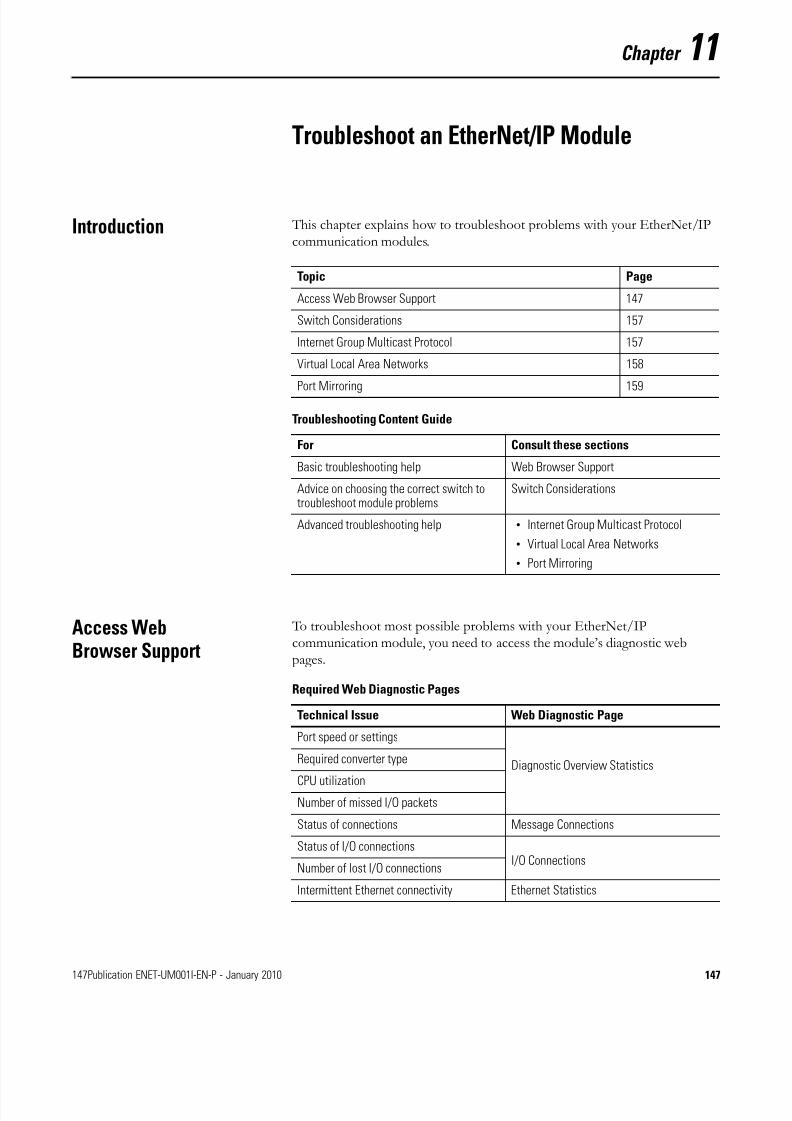
8/13/2019 EtherNet-IP Modules in Logix5000 Control Systems User Manual
http://slidepdf.com/reader/full/ethernet-ip-modules-in-logix5000-control-systems-user-manual 147/230
147Publication ENET-UM001I-EN-P - January 2010 147
Chapter 11
Troubleshoot an EtherNet/IP Module
Introduction This chapter explains how to troubleshoot problems with your EtherNet/IPcommunication modules.
Access WebBrowser Support
To troubleshoot most possible problems with your EtherNet/IPcommunication module, you need to access the module’s diagnostic webpages.
Topic Page
Access Web Browser Support 147
Switch Considerations 157
Internet Group Multicast Protocol 157
Virtual Local Area Networks 158
Port Mirroring 159
Troubleshooting Content Guide
For Consult these sections
Basic troubleshooting help Web Browser Support
Advice on choosing the correct switch totroubleshoot module problems
Switch Considerations
Advanced troubleshooting help • Internet Group Multicast Protocol
• Virtual Local Area Networks
• Port Mirroring
Required Web Diagnostic Pages
Technical Issue Web Diagnostic Page
Port speed or settings
Diagnostic Overview StatisticsRequired converter type
CPU utilizationNumber of missed I/O packets
Status of connections Message Connections
Status of I/O connections I/O Connections
Number of lost I/O connections
Intermittent Ethernet connectivity Ethernet Statistics
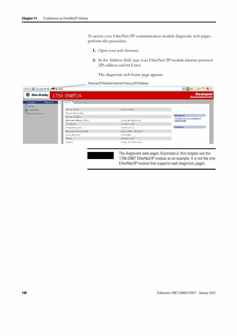
8/13/2019 EtherNet-IP Modules in Logix5000 Control Systems User Manual
http://slidepdf.com/reader/full/ethernet-ip-modules-in-logix5000-control-systems-user-manual 148/230
148 Publication ENET-UM001I-EN-P - January 2010
Chapter 11 Troubleshoot an EtherNet/IP Module
To access your EtherNet/IP communication module diagnostic web pages,perform this procedure.
1. Open your web browser.
2. In the Address field, type your EtherNet/IP module internet protocol(IP) address and hit Enter.
The diagnostic web home page appears.
Ethernet/IP Module Internet Protocol (IP) Address
IMPORTANT The diagnostic web pages illustrated in this chapter use the1756-ENBT EtherNet/IP module as an example. It is not the onlyEtherNet/IP module that supports web diagnostic pages.
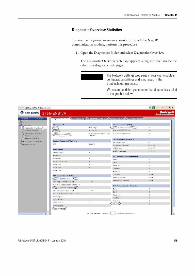
8/13/2019 EtherNet-IP Modules in Logix5000 Control Systems User Manual
http://slidepdf.com/reader/full/ethernet-ip-modules-in-logix5000-control-systems-user-manual 149/230
Publication ENET-UM001I-EN-P - January 2010 149
Troubleshoot an EtherNet/IP Module Chapter 11
Diagnostic Overview Statistics
To view the diagnostic overview statistics for your EtherNet/IPcommunication module, perform this procedure.
1. Open the Diagnostics folder and select Diagnostics Overview.
The Diagnostic Overview web page appears, along with the tabs for the
other four diagnostic web pages.
IMPORTANT The Network Settings web page shows your module’sconfiguration settings and is not used in thetroubleshooting process.
We recommend that you monitor the diagnostics circledin the graphic below.

8/13/2019 EtherNet-IP Modules in Logix5000 Control Systems User Manual
http://slidepdf.com/reader/full/ethernet-ip-modules-in-logix5000-control-systems-user-manual 150/230
150 Publication ENET-UM001I-EN-P - January 2010
Chapter 11 Troubleshoot an EtherNet/IP Module
2. Review the values in the Ethernet Link table.
If And you Then
Speed is 100 or1000Mbps
Do not want to change your portspeed
No action is required.
Important: 100 Mbps is the default port speed.
Want to reduce your port speed to 10Mbps
You must manually configure your module and reset your module.See Configure the Module with RSLinx Software on page 48.
10Mbps
Want to increase your port speed to100 Mbps
Reset your module or see Configure the Module with RSLinx Softwareon page 48.
Do not want to change your portspeed
No action is required.
Duplex is Full Are sending large amounts of data No action is required.
Important: Full Duplex is the default port setting.
Full-duplex ports eliminate collisions because each device has separatechannels for the transmission and receipt of large amounts of data.
Half Are not sending large amounts of data No action is required.
Important: Delays due to collisions or switch traffic are usuallynegligible, but can become a problem if you need to send a lot of data.
Are sending large amounts of data Change your module’s Duplex setting to Full. See Configure the Modulewith RSLinx Software on page 48.
AutonegotiateStatus is
Speedand/orDuplex
Are using a fiber converter Change your module’s Autonegotiate status to None. See Configure theModule with RSLinx Software on page 48.
Important: Fiber links do not support autonegotiation.
Are not using a fiber converter No action is required.
Important: Speed and/or Duplex is the default setting.
Autonegotation enables devices to select the best way to communicatewithout you having to do any configuring. All devices with an Ethernetspeed rating of 100 Mbps are required to support autonegotiation.
None Are not using a fiber converter Change your module’s Autonegotiate status to Speed and/or Duplex.
See Configure the Module with RSLinx Software on page 48.
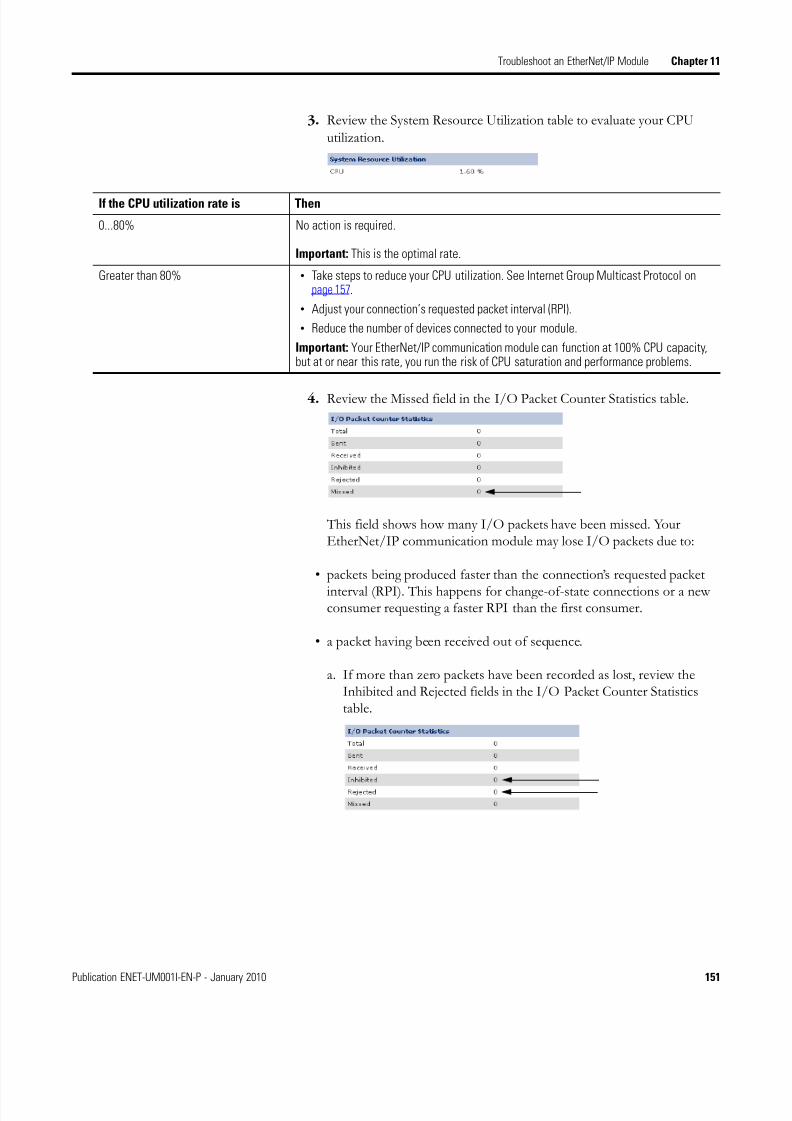
8/13/2019 EtherNet-IP Modules in Logix5000 Control Systems User Manual
http://slidepdf.com/reader/full/ethernet-ip-modules-in-logix5000-control-systems-user-manual 151/230
Publication ENET-UM001I-EN-P - January 2010 151
Troubleshoot an EtherNet/IP Module Chapter 11
3. Review the System Resource Utilization table to evaluate your CPU
utilization.
4. Review the Missed field in the I/O Packet Counter Statistics table.
This field shows how many I/O packets have been missed. YourEtherNet/IP communication module may lose I/O packets due to:
• packets being produced faster than the connection’s requested packet
interval (RPI). This happens for change-of-state connections or a newconsumer requesting a faster RPI than the first consumer.
• a packet having been received out of sequence.
a. If more than zero packets have been recorded as lost, review theInhibited and Rejected fields in the I/O Packet Counter Statisticstable.
If the CPU utilization rate is Then
0...80% No action is required.
Important: This is the optimal rate.
Greater than 80% • Take steps to reduce your CPU utilization. See Internet Group Multicast Protocol onpage 157.
• Adjust your connection’s requested packet interval (RPI).
• Reduce the number of devices connected to your module.
Important: Your EtherNet/IP communication module can function at 100% CPU capacity,but at or near this rate, you run the risk of CPU saturation and performance problems.
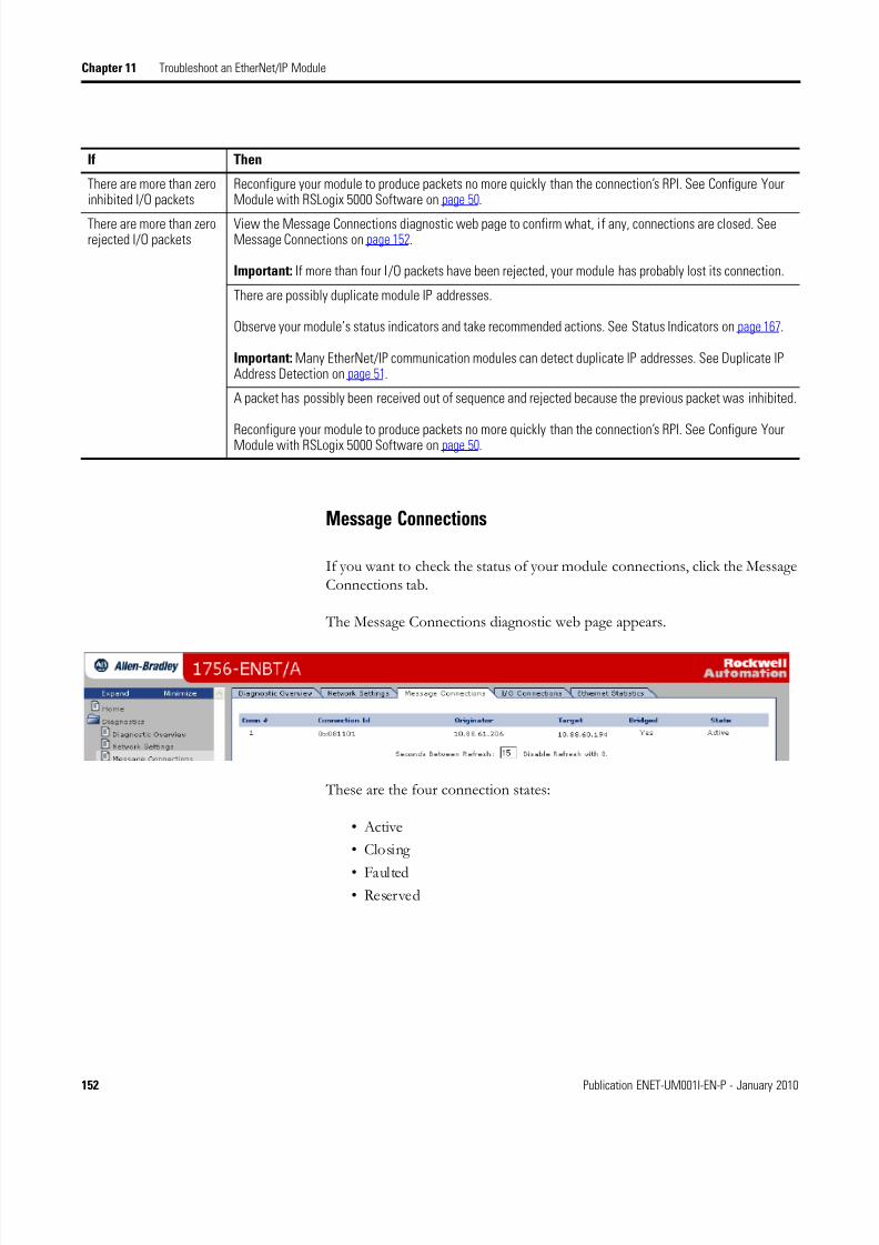
8/13/2019 EtherNet-IP Modules in Logix5000 Control Systems User Manual
http://slidepdf.com/reader/full/ethernet-ip-modules-in-logix5000-control-systems-user-manual 152/230
152 Publication ENET-UM001I-EN-P - January 2010
Chapter 11 Troubleshoot an EtherNet/IP Module
Message Connections
If you want to check the status of your module connections, click the MessageConnections tab.
The Message Connections diagnostic web page appears.
These are the four connection states:
• Active
• Closing
• Faulted• Reserved
If Then
There are more than zeroinhibited I/O packets
Reconfigure your module to produce packets no more quickly than the connection’s RPI. See Configure YourModule with RSLogix 5000 Software on page 50.
There are more than zerorejected I/O packets
View the Message Connections diagnostic web page to confirm what, if any, connections are closed. SeeMessage Connections on page 152.
Important: If more than four I/O packets have been rejected, your module has probably lost its connection.
There are possibly duplicate module IP addresses.
Observe your module’s status indicators and take recommended actions. See Status Indicators on page 167.
Important: Many EtherNet/IP communication modules can detect duplicate IP addresses. See Duplicate IPAddress Detection on page 51.
A packet has possibly been received out of sequence and rejected because the previous packet was inhibited.
Reconfigure your module to produce packets no more quickly than the connection’s RPI. See Configure YourModule with RSLogix 5000 Software on page 50.

8/13/2019 EtherNet-IP Modules in Logix5000 Control Systems User Manual
http://slidepdf.com/reader/full/ethernet-ip-modules-in-logix5000-control-systems-user-manual 153/230
Publication ENET-UM001I-EN-P - January 2010 153
Troubleshoot an EtherNet/IP Module Chapter 11
I/O Connections
If you want to check the status of your module’s I/O connections, click theI/O Connections tab.
The I/O Connections diagnostic web page appears.
The Lost column shows the number of I/O packets that were not received.
Ethernet Statistics
Your EtherNet/IP communication module may experience intermittentnetwork connectivity due to:
• a duplex mismatch.
• electrical noise induced into a cable or resulting from a Logix/switchground potential difference.
• bad hardware, such as a cable or switch part.
Before troubleshooting this problem, familiarize yourself with these Ethernetstatistics, or media counters.
IMPORTANT To troubleshoot lost I/O packets, review the I/O Packet CounterStatistics table in the Diagnostic Overview tab. See page 151.
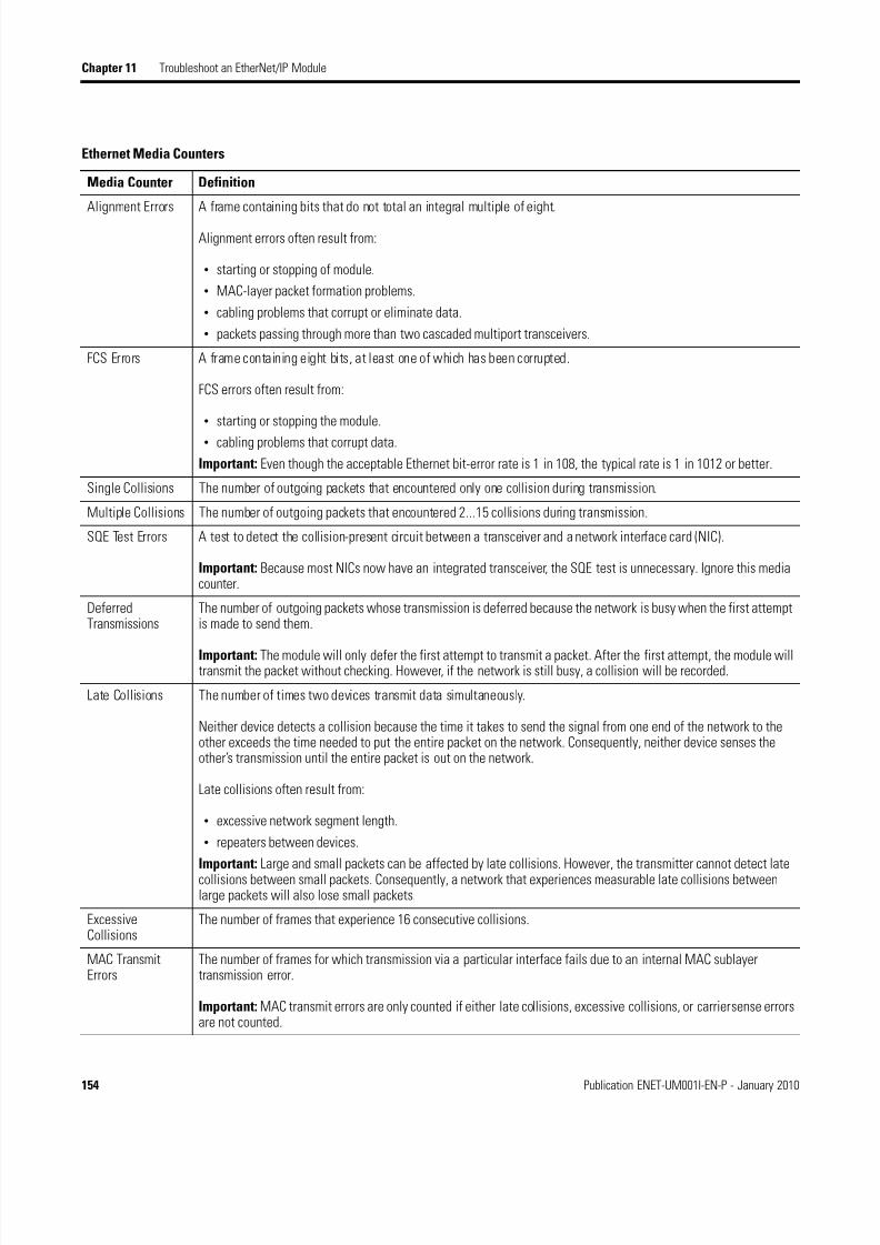
8/13/2019 EtherNet-IP Modules in Logix5000 Control Systems User Manual
http://slidepdf.com/reader/full/ethernet-ip-modules-in-logix5000-control-systems-user-manual 154/230
154 Publication ENET-UM001I-EN-P - January 2010
Chapter 11 Troubleshoot an EtherNet/IP Module
Ethernet Media Counters
Media Counter Definition
Alignment Errors A frame containing bits that do not total an integral multiple of eight.
Alignment errors often result from:
• starting or stopping of module.
• MAC-layer packet formation problems.
• cabling problems that corrupt or eliminate data.
• packets passing through more than two cascaded multiport transceivers.
FCS Errors A frame containing eight bits, at least one of which has been corrupted.
FCS errors often result from:
• starting or stopping the module.
• cabling problems that corrupt data.
Important: Even though the acceptable Ethernet bit-error rate is 1 in 108, the typical rate is 1 in 1012 or better.
Single Collisions The number of outgoing packets that encountered only one collision during transmission.
Multiple Collisions The number of outgoing packets that encountered 2...15 collisions during transmission.
SQE Test Errors A test to detect the collision-present circuit between a transceiver and a network interface card (NIC).
Important: Because most NICs now have an integrated transceiver, the SQE test is unnecessary. Ignore this mediacounter.
DeferredTransmissions
The number of outgoing packets whose transmission is deferred because the network is busy when the first attemptis made to send them.
Important: The module will only defer the first attempt to transmit a packet. After the first attempt, the module willtransmit the packet without checking. However, if the network is still busy, a collision will be recorded.
Late Collisions The number of times two devices transmit data simultaneously.
Neither device detects a collision because the time it takes to send the signal from one end of the network to theother exceeds the time needed to put the entire packet on the network. Consequently, neither device senses theother’s transmission until the entire packet is out on the network.
Late collisions often result from:
• excessive network segment length.
• repeaters between devices.
Important: Large and small packets can be affected by late collisions. However, the transmitter cannot detect latecollisions between small packets. Consequently, a network that experiences measurable late collisions betweenlarge packets will also lose small packets.
ExcessiveCollisions
The number of frames that experience 16 consecutive collisions.
MAC TransmitErrors
The number of frames for which transmission via a particular interface fails due to an internal MAC sublayertransmission error.
Important: MAC transmit errors are only counted if either late collisions, excessive collisions, or carrier sense errorsare not counted.

8/13/2019 EtherNet-IP Modules in Logix5000 Control Systems User Manual
http://slidepdf.com/reader/full/ethernet-ip-modules-in-logix5000-control-systems-user-manual 155/230
Publication ENET-UM001I-EN-P - January 2010 155
Troubleshoot an EtherNet/IP Module Chapter 11
To troubleshoot intermittent Ethernet connectivity, perform this procedure.
1. Click the Ethernet Statistics tab.
The Ethernet Statistics diagnostic web page appears.
MAC ReceiveErrors
The number of frames for which reception via a particular interface fails due to an internal MAC sublayertransmission error.
Important: MAC receive errors are only counted if either the frame too long count, alignment errors, or FCS errorsare not counted.
Carrier SenseErrors
Carrier sense errors fall into these categories:
• No Carrier Sense Present - The number of times the carrier is not present when a transmission starts.
• Carrier Sense Lost - The number of times the carrier is lost during a transmission.
Carrier sense errors usually indicate a problem with a cable on the Ethernet infrastructure.
Frame Too Long The number of incoming packets that exceed the maximum Ethernet packet size.
Ethernet Media Counters
Media Counter Definition
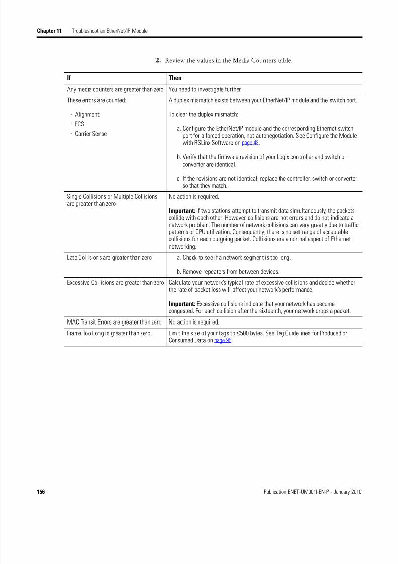
8/13/2019 EtherNet-IP Modules in Logix5000 Control Systems User Manual
http://slidepdf.com/reader/full/ethernet-ip-modules-in-logix5000-control-systems-user-manual 156/230
156 Publication ENET-UM001I-EN-P - January 2010
Chapter 11 Troubleshoot an EtherNet/IP Module
2. Review the values in the Media Counters table.
If Then
Any media counters are greater than zero You need to investigate further.
These errors are counted:
· Alignment
· FCS
· Carrier Sense
A duplex mismatch exists between your EtherNet/IP module and the switch port.
To clear the duplex mismatch:
a. Configure the EtherNet/IP module and the corresponding Ethernet switchport for a forced operation, not autonegotiation. See Configure the Modulewith RSLinx Software on page 48.
b. Verify that the firmware revision of your Logix controller and switch orconverter are identical.
c. If the revisions are not identical, replace the controller, switch or converterso that they match.
Single Collisions or Multiple Collisionsare greater than zero
No action is required.
Important: If two stations attempt to transmit data simultaneously, the packetscollide with each other. However, collisions are not errors and do not indicate anetwork problem. The number of network collisions can vary greatly due to trafficpatterns or CPU utilization. Consequently, there is no set range of acceptablecollisions for each outgoing packet. Coll isions are a normal aspect of Ethernetnetworking.
Late Collisions are greater than zero a. Check to see if a network segment is too long.
b. Remove repeaters from between devices.
Excessive Collisions are greater than zero Calculate your network’s typical rate of excessive collisions and decide whetherthe rate of packet loss will affect your network’s performance.
Important: Excessive collisions indicate that your network has becomecongested. For each collision after the sixteenth, your network drops a packet.
MAC Transit Errors are greater than zero No action is required.
Frame Too Long is greater than zero Limit the size of your tags to≤ 500 bytes. See Tag Guidelines for Produced orConsumed Data on page 95.
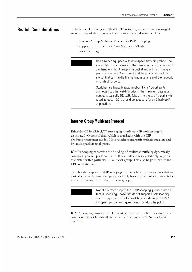
8/13/2019 EtherNet-IP Modules in Logix5000 Control Systems User Manual
http://slidepdf.com/reader/full/ethernet-ip-modules-in-logix5000-control-systems-user-manual 157/230
Publication ENET-UM001I-EN-P - January 2010 157
Troubleshoot an EtherNet/IP Module Chapter 11
Switch Considerations To help troubleshoot your EtherNet/IP network, you must use a managedswitch. Some of the important features in a managed switch include:
• Internet Group Multicast Protocol (IGMP) snooping.
• support for Virtual Local Area Networks (VLAN).• port mirroring.
Internet Group Multicast Protocol
EtherNet/IP implicit (I/O) messaging mostly uses IP multicasting todistribute I/O control data, which is consistent with the CIPproduced/consumer model. Most switches retransmit multicast packets and
broadcast packets to all ports.
IGMP snooping constrains the flooding of multicast traffic by dynamicallyconfiguring switch ports so that multicast traffic is forwarded only to portsassociated with a particular IP multicast group. This also helps minimize theCPU utilization rate.
Switches that support IGMP snooping learn which ports have devices that arepart of a particular multicast group and only forward the multicast packets tothe ports that are part of the multicast group.
IGMP snooping cannot control unicast or broadcast traffic. To learn how tocontrol unicast or broadcast traffic, see Virtual Local Area Networks onpage 158.
IMPORTANT Use a switch equipped with wire-speed switching fabric. Theswitch fabric is a measure of the maximum traffic that a switchcan handle without dropping a packet and without storing apacket in memory. Wire-speed switching fabric refers to aswitch that can handle the maximum data rate of the networkon each of its ports.
Switches are typically rated in Gbps. For a 10-port switchconnected to EtherNet/IP products, the maximum data rate
needed is typically 100...200 MB/s. Therefore, a 10-port-switchrated at least 1 GB/s should be adequate for an EtherNet/IPapplication.
IMPORTANT Not all switches support the IGMP snooping querier function,that is, snooping. Those that do not support IGMP snoopingquerier require a router. For switches that do support IGMPsnooping, you can configure them to conduct the polling.
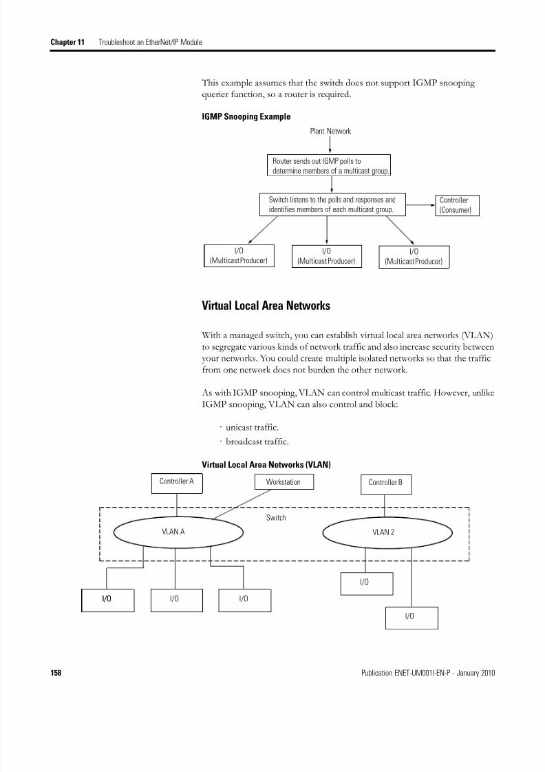
8/13/2019 EtherNet-IP Modules in Logix5000 Control Systems User Manual
http://slidepdf.com/reader/full/ethernet-ip-modules-in-logix5000-control-systems-user-manual 158/230
158 Publication ENET-UM001I-EN-P - January 2010
Chapter 11 Troubleshoot an EtherNet/IP Module
This example assumes that the switch does not support IGMP snoopingquerier function, so a router is required.
IGMP Snooping Example
Virtual Local Area Networks
With a managed switch, you can establish virtual local area networks (VLAN)to segregate various kinds of network traffic and also increase security betweenyour networks. You could create multiple isolated networks so that the trafficfrom one network does not burden the other network.
As with IGMP snooping, VLAN can control multicast traffic. However, unlike
IGMP snooping, VLAN can also control and block:
· unicast traffic.
· broadcast traffic.
Virtual Local Area Networks (VLAN)
Plant Network
Router sends out IGMP polls to
determine members of a multicast group.
Switch listens to the polls and responses and
identifies members of each multicast group.Controller
(Consumer)
I/O
(Multicast Producer)I/O
(Multicast Producer)I/O
(Multicast Producer)
Controller A Workstation Controller B
VLAN A VLAN 2
I/O I/O I/OI/O
I/O
I/O
Switch

8/13/2019 EtherNet-IP Modules in Logix5000 Control Systems User Manual
http://slidepdf.com/reader/full/ethernet-ip-modules-in-logix5000-control-systems-user-manual 159/230
Publication ENET-UM001I-EN-P - January 2010 159
Troubleshoot an EtherNet/IP Module Chapter 11
Port Mirroring
Select a managed switch that supports port mirroring. With port mirroring,you can direct frames being transmitted on one port to another port for
analysis by a traffic analyzer. Besides monitoring your Ethernet mediacounters, port mirroring enables you to immediately spot anomalies in trafficflow. A traffic analyzer can monitor the traffic on a given port andtroubleshoot a problem. Without port mirroring, you cannot see frames onother ports. With hubs this is not an issue because all frames are transmittedout all ports. The effective support and maintenance of Ethernet networksoften depends on reliable traffic analysis.
The benefits of port mirroring include:
• monitoring explicit messages between controllers.
• monitoring implicit or I/O traffic.

8/13/2019 EtherNet-IP Modules in Logix5000 Control Systems User Manual
http://slidepdf.com/reader/full/ethernet-ip-modules-in-logix5000-control-systems-user-manual 160/230
160 Publication ENET-UM001I-EN-P - January 2010
Chapter 11 Troubleshoot an EtherNet/IP Module
Notes:

8/13/2019 EtherNet-IP Modules in Logix5000 Control Systems User Manual
http://slidepdf.com/reader/full/ethernet-ip-modules-in-logix5000-control-systems-user-manual 161/230
161Publication ENET-UM001I-EN-P - January 2010 161
Chapter 12
USB Serial Communication
Introduction This chapter describes how to configure RSLinx software to use a USB portand how you can and cannot flash upgrade firmware via a USB port.
Two EtherNet/IP modules support USB serial communication.
• 1756-EN2F
• 1756-EN2T
• 1756-EN2TR
• 1756-EN2TXT
Set Up the Hardware In this example, the controller in the local chassis produces a tag that theLogix5000 controller in the remote chassis consumes. The local controller canalso send a MSG instruction to the remote controller.
Sharing Data and Transferring Messages
Topic Page
Configure a Module Via the USB Port 162
Flash Upgrade Firmware through a USB Port 165
A
C
USB connection
EtherNet/IP
B
Item Description
A Local chassis containing a Logix5000 controller and a 1756-EN2T,1756-EN2TR, 1756-EN2TXT, or 1756-EN2F module
B Remote chassis containing a Logix5000 controller with an EtherNet/IPconnection
C Remote chassis containing Logix5000 controller

8/13/2019 EtherNet-IP Modules in Logix5000 Control Systems User Manual
http://slidepdf.com/reader/full/ethernet-ip-modules-in-logix5000-control-systems-user-manual 162/230
162 Publication ENET-UM001I-EN-P - January 2010
Chapter 12 USB Serial Communication
Configure a Module Viathe USB Port
The module has a USB device port. To use the USB port, you must haveRSLinx software, version 2.51 or later, installed on your computer. Use a USBcable to connect your computer to the USB port. The connection lets youdownload programs to controllers and configure other devices, which areaccessible by the module, directly from your computer.
WARNI NGThe USB port is intended for temporary local programmingpurposes only and not intended for permanent connection. If
you connect or disconnect the USB cable with power applied tothis module or any device on the USB network, an electrical arccan occur. This could cause an explosion in hazardous locationinstallations. A Samtec Inc. RSP-119350 USB cable is requiredto maintain hazardous location certifications.
ATTENTIONBe sure that power is removed or the area is nonhazardousbefore proceeding
IMPORTANT The USB cable is not to exceed 3.0 m (9.84 ft) and must notcontain hubs.

8/13/2019 EtherNet-IP Modules in Logix5000 Control Systems User Manual
http://slidepdf.com/reader/full/ethernet-ip-modules-in-logix5000-control-systems-user-manual 163/230
Publication ENET-UM001I-EN-P - January 2010 163
USB Serial Communication Chapter 12
Set Up a USB Driver
To configure RSLinx software to use a USB port, you need to first set up aUSB driver. To set up a USB driver, perform this procedure.
1. Connect your EtherNet/IP module to your computer by installing aUSB cable in your module’s USB port.
The RSLinx Found New Hardware Wizard dialog box appears.
2. Select Install the Software Automatically.
3. Click Next.
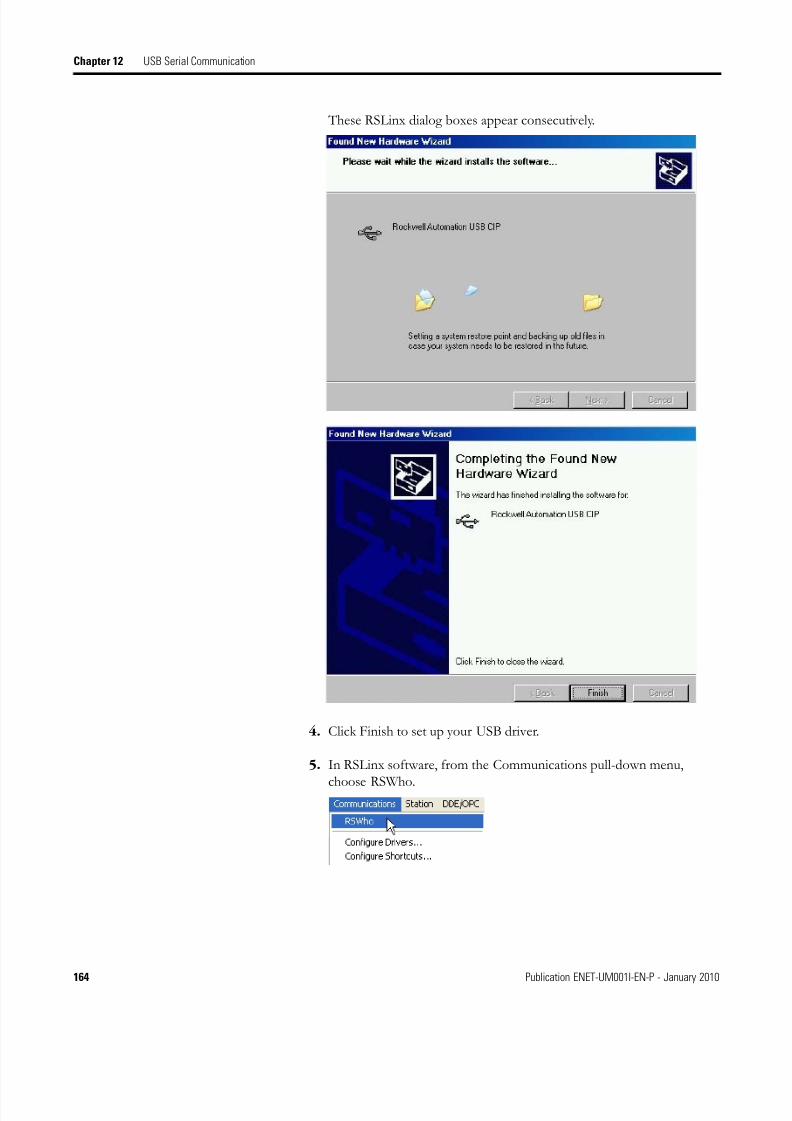
8/13/2019 EtherNet-IP Modules in Logix5000 Control Systems User Manual
http://slidepdf.com/reader/full/ethernet-ip-modules-in-logix5000-control-systems-user-manual 164/230
164 Publication ENET-UM001I-EN-P - January 2010
Chapter 12 USB Serial Communication
These RSLinx dialog boxes appear consecutively.
4. Click Finish to set up your USB driver.
5. In RSLinx software, from the Communications pull-down menu,
choose RSWho.
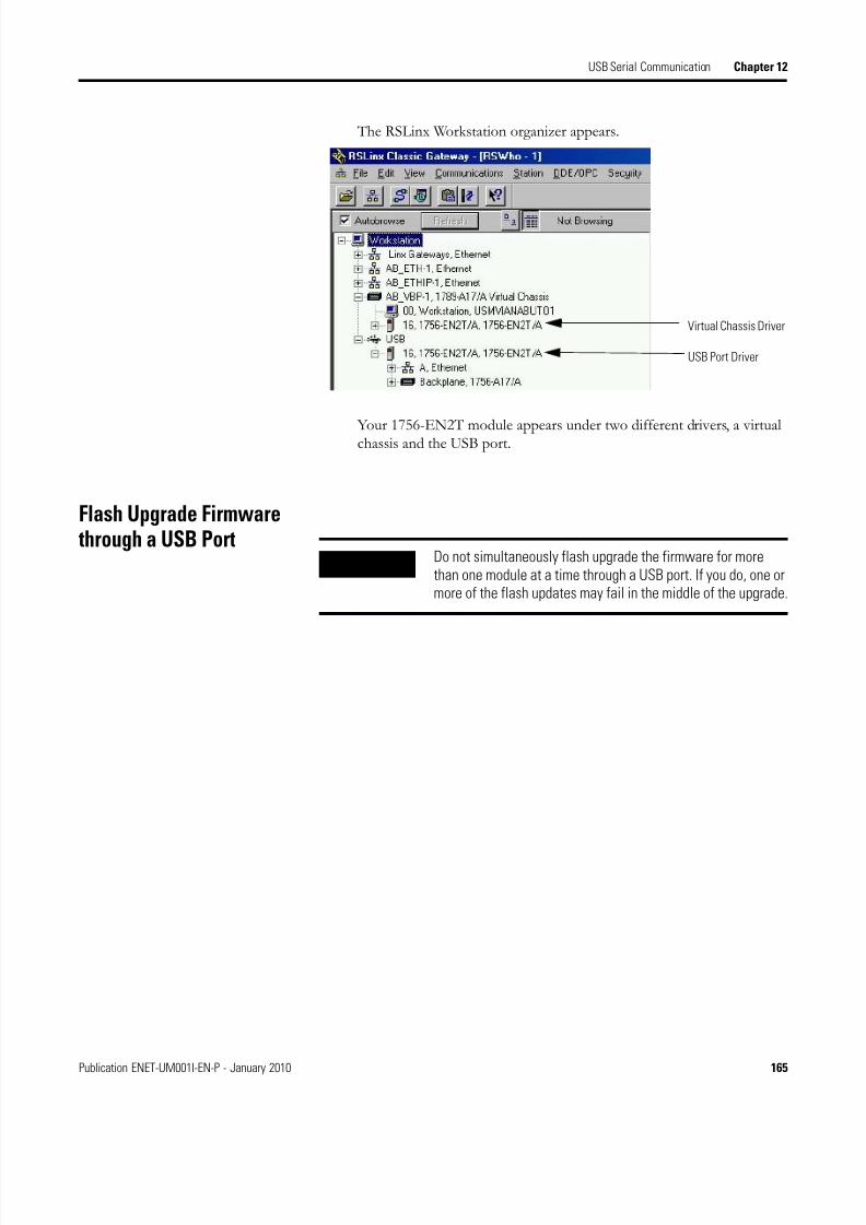
8/13/2019 EtherNet-IP Modules in Logix5000 Control Systems User Manual
http://slidepdf.com/reader/full/ethernet-ip-modules-in-logix5000-control-systems-user-manual 165/230
Publication ENET-UM001I-EN-P - January 2010 165
USB Serial Communication Chapter 12
The RSLinx Workstation organizer appears.
Your 1756-EN2T module appears under two different drivers, a virtualchassis and the USB port.
Flash Upgrade Firmwarethrough a USB Port
Virtual Chassis Driver
USB Port Driver
IMPORTANT Do not simultaneously flash upgrade the firmware for morethan one module at a time through a USB port. If you do, one ormore of the flash updates may fail in the middle of the upgrade.

8/13/2019 EtherNet-IP Modules in Logix5000 Control Systems User Manual
http://slidepdf.com/reader/full/ethernet-ip-modules-in-logix5000-control-systems-user-manual 166/230
166 Publication ENET-UM001I-EN-P - January 2010
Chapter 12 USB Serial Communication
Notes:

8/13/2019 EtherNet-IP Modules in Logix5000 Control Systems User Manual
http://slidepdf.com/reader/full/ethernet-ip-modules-in-logix5000-control-systems-user-manual 167/230
Publication ENET-UM001I-EN-P - January 2010 167
Appendix A
Status Indicators
Introduction This appendix provides status indicator descriptions for several
communication modules, adapters, and controllers.
Status indicators common to all modules, cards and controllers presented in
this chapter include:
• Link Status Indicator (LNK).
• Network Status Indicator (NET).
• Health Status Indicator (OK).
Topic Page
1756-ENBT EtherNet/IP Module Status Indicators 169
1756-EN2F EtherNet/IP Module Status Indicators 171
1756-EN2T EtherNet/IP Module Status Indicators 173
1756-EN2TR EtherNet/IP Module Status Indicators 175
1756-EN2TXT ControlLogix-XT EtherNet/IP Bridge Module StatusIndicators
177
1769-L23E-QB1B and 1769-L23E-QBFC1B Controllers StatusIndicators
178
1769-L32E and 1769-L35E Controllers Status Indicators 183
1768-ENBT Module Status Indicators 185
1783-ETAP, 1783-ETAP1F, and 1783-ETAP2F EtherNet/IP Tap StatusIndicators
187
1788-ENBT EtherNet/IP Daughtercard Status Indicators 189
1734-AENT and 1734-AENTR EtherNet/IP POINT I/O Adapter StatusIndicators
192
1738-AENTR ArmorPOINT I/O 2-port EtherNet/IP Adapter StatusIndicators
195
1794-AENT EtherNet/IP FLEX I/O Adapter Status Indicators 199
20-COMM-E Module Status Indicators 201
22-COMM-E Module Status Indicators 205
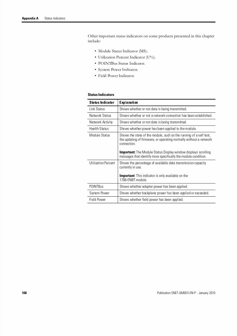
8/13/2019 EtherNet-IP Modules in Logix5000 Control Systems User Manual
http://slidepdf.com/reader/full/ethernet-ip-modules-in-logix5000-control-systems-user-manual 168/230
168 Publication ENET-UM001I-EN-P - January 2010
Appendix A Status Indicators
Other important status indicators on some products presented in this chapterinclude:
• Module Status Indicator (MS).
• Utilization Percent Indicator (U%).• POINTBus Status Indicator.
• System Power Indicator.
• Field Power Indicator.
Status Indicators
Status Indicator Explanation
Link Status Shows whether or not data is being transmitted.
Network Status Shows whether or not a network connection has been established.
Network Activity Shows whether or not data is being transmitted.
Health Status Shows whether power has been applied to the module.
Module Status Shows the state of the module, such as the running of a self test,the updating of firmware, or operating normally without a networkconnection.
Important: The Module Status Display window displays scrollingmessages that identify more specifically the module condition.
Utilization Percent Shows the percentage of available data transmission capacitycurrently in use.
Important: This indicator is only available on the1788-ENBT module.
POINTBus Shows whether adapter power has been applied.
System Power Shows whether backplane power has been applied or exceeded.
Field Power Shows whether field power has been applied.

8/13/2019 EtherNet-IP Modules in Logix5000 Control Systems User Manual
http://slidepdf.com/reader/full/ethernet-ip-modules-in-logix5000-control-systems-user-manual 169/230
Publication ENET-UM001I-EN-P - January 2010 169
Status Indicators Appendix A
1756-ENBT EtherNet/IPModule Status Indicators
The 1756-ENBT EtherNet/IP communication module has several statusindicators.
1756-ENBT EtherNet/IP Module Status Indicators
If the NET status indicator is off , take the following actions.
1. Verify there is chassis power.
2. Verify that the module is completely inserted into the chassis andbackplane.
3. Make sure the module has been configured.
Module Status
Display
Health Status Indicator
Network Status Indicator
Link Status
Indicator
Network (NET) Status Indicator
Indicatorcondition
Status Description
Off The module is not powered, or does not have an IP address.
Follow the corrective action below.
Flashinggreen
IPAddress/Mask/GatewayConfig Invalid
The controller has an IP address, but no CIP connections are established.
If no connections are configured, this is normal operation. No action is required.
If connections are configured, check connection originator for connection error code.
Green XXX.XXX.XXX.XXX OK The module has an IP address and at least one established connection. This is normal operationand no action is required.
Flashing red Class x ConnectionTimeout
One or more of the connections in which the module is the target has timed out. Reestablish theconnection.
Red Duplicate IP XX:XX ofxx:xx:xx is using the IPaddress of this module
A duplicate IP address has been detected. Make sure that the the IP address assigned to thismodule is not identical to that of any other device already on the network.
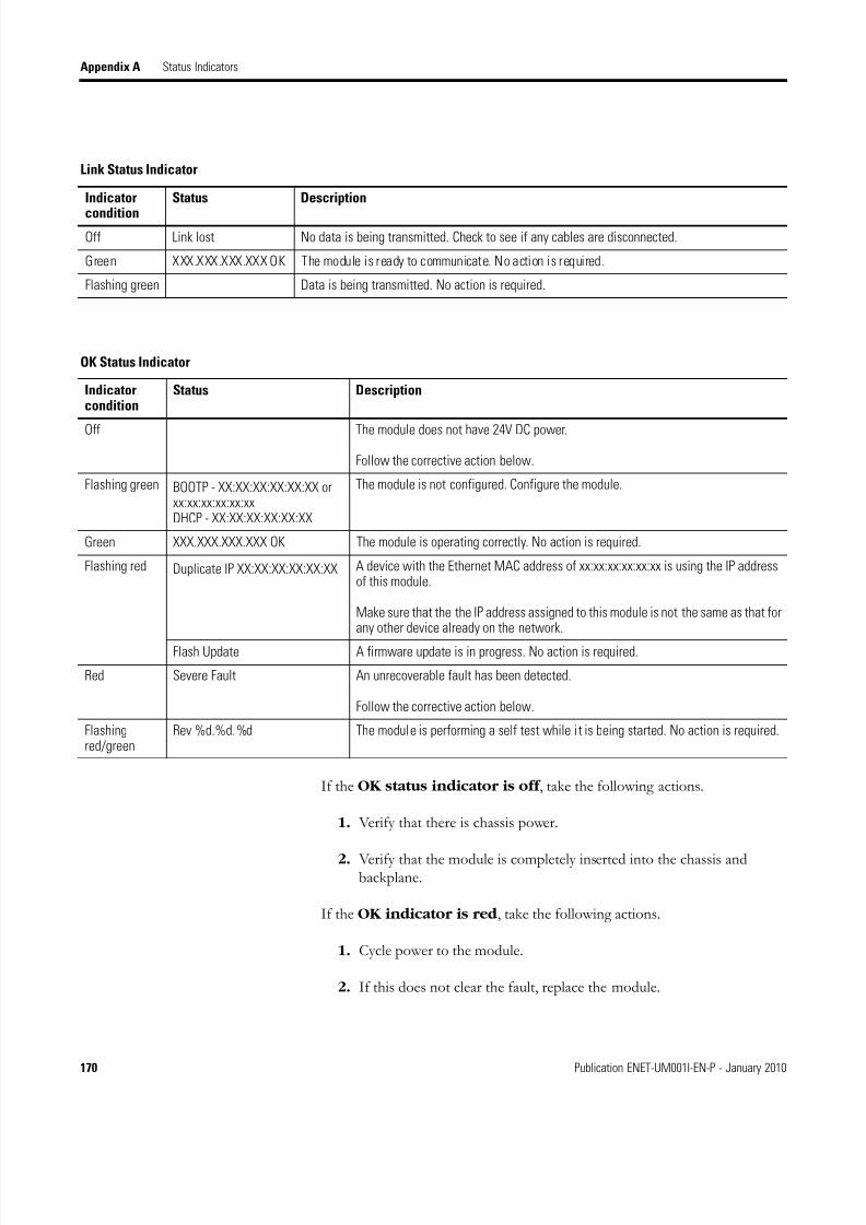
8/13/2019 EtherNet-IP Modules in Logix5000 Control Systems User Manual
http://slidepdf.com/reader/full/ethernet-ip-modules-in-logix5000-control-systems-user-manual 170/230
170 Publication ENET-UM001I-EN-P - January 2010
Appendix A Status Indicators
If the OK status indicator is off , take the following actions.
1. Verify that there is chassis power.
2. Verify that the module is completely inserted into the chassis andbackplane.
If the OK indicator is red , take the following actions.
1. Cycle power to the module.
2. If this does not clear the fault, replace the module.
Link Status Indicator
Indicator
condition
Status Description
Off Link lost No data is being transmitted. Check to see if any cables are disconnected.
Green XXX.XXX.XXX.XXX OK The module is ready to communicate. No action is required.
Flashing green Data is being transmitted. No action is required.
OK Status Indicator
Indicatorcondition
Status Description
Off The module does not have 24V DC power.
Follow the corrective action below.
Flashing green BOOTP - XX:XX:XX:XX:XX:XX orxx:xx:xx:xx:xx:xxDHCP - XX:XX:XX:XX:XX:XX
The module is not configured. Configure the module.
Green XXX.XXX.XXX.XXX OK The module is operating correctly. No action is required.
Flashing red Duplicate IP XX:XX:XX:XX:XX:XX A device with the Ethernet MAC address of xx:xx:xx:xx:xx:xx is using the IP addressof this module.
Make sure that the the IP address assigned to this module is not the same as that forany other device already on the network.
Flash Update A firmware update is in progress. No action is required.
Red Severe Fault An unrecoverable fault has been detected.
Follow the corrective action below.
Flashingred/green
Rev %d.%d.%d The module is performing a self test while it is being started. No action is required.

8/13/2019 EtherNet-IP Modules in Logix5000 Control Systems User Manual
http://slidepdf.com/reader/full/ethernet-ip-modules-in-logix5000-control-systems-user-manual 171/230
Publication ENET-UM001I-EN-P - January 2010 171
Status Indicators Appendix A
1756-EN2F EtherNet/IPModule Status Indicators
The 1756-EN2F EtherNet/IP communication module has severalstatus indicators.
1756-EN2F EtherNet/IP Fiber Module Status Indicators
If the NET status indicator is off , take the following actions.
1. Verify there is chassis power.
2. Verify that the module is completely inserted into the chassis andbackplane.
3. Make sure the module has been configured with a valid IP address.
Module Status
Display
Health Status Indicator
Network Status Indicator
Link Status
Indicator
Network (NET) Status Indicator
Indicatorcondition
Status Description
Off The module is not powered, or does not have an IP address.
Follow the corrective action below.
Flashinggreen
IPAddress/Mask/Gateway Config Invalid
The controller has an IP address, but no CIP connections are established.
If no connections are configured, this is normal operation. No action is required.
If connections are configured, check connection originator for connection error code.
Green XXX.XXX.XXX.XXX OK The module has an IP address and at least one established connection. No action is required.
Flashingred
Class x ConnectionTimeout
One or more of the connections in which the module is the target has timed out. Reestablish theconnection.
Red Duplicate IP XX:XX ofxx:xx:xx is using the IPaddress of thismodule
A duplicate IP address has been detected. Make sure that the the IP address assigned to thismodule is not identical to that of any other device already on the network.
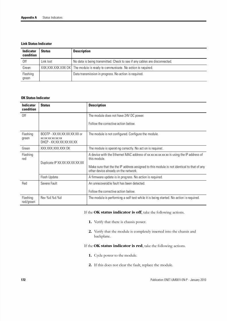
8/13/2019 EtherNet-IP Modules in Logix5000 Control Systems User Manual
http://slidepdf.com/reader/full/ethernet-ip-modules-in-logix5000-control-systems-user-manual 172/230
172 Publication ENET-UM001I-EN-P - January 2010
Appendix A Status Indicators
If the OK status indicator is off , take the following actions.
1. Verify that there is chassis power.
2. Verify that the module is completely inserted into the chassis andbackplane.
If the OK status indicator is red , take the following actions.
1. Cycle power to the module.
2. If this does not clear the fault, replace the module.
Link Status Indicator
Indicator
condition
Status Description
Off Link lost No data is being transmitted. Check to see if any cables are disconnected.
Green XXX.XXX.XXX.XXX OK The module is ready to communicate. No action is required.
Flashinggreen
Data transmission in progress. No action is required.
OK Status Indicator
Indicatorcondition
Status Description
Off The module does not have 24V DC power.
Follow the corrective action below.
Flashinggreen
BOOTP - XX:XX:XX:XX:XX:XX orxx:xx:xx:xx:xx:xxDHCP - XX:XX:XX:XX:XX:XX
The module is not configured. Configure the module.
Green XXX.XXX.XXX.XXX OK The module is operating correctly. No action is required.
Flashingred
Duplicate IP XX:XX:XX:XX:XX:XX
A device with the Ethernet MAC address of xx:xx:xx:xx:xx:xx is using the IP address ofthis module.
Make sure that the the IP address assigned to this module is not identical to that of anyother device already on the network.
Flash Update A firmware update is in progress. No action is required.
Red Severe Fault An unrecoverable fault has been detected.
Follow the corrective action below.
Flashingred/green
Rev %d.%d.%d The module is performing a self test while it is being started. No action is required.
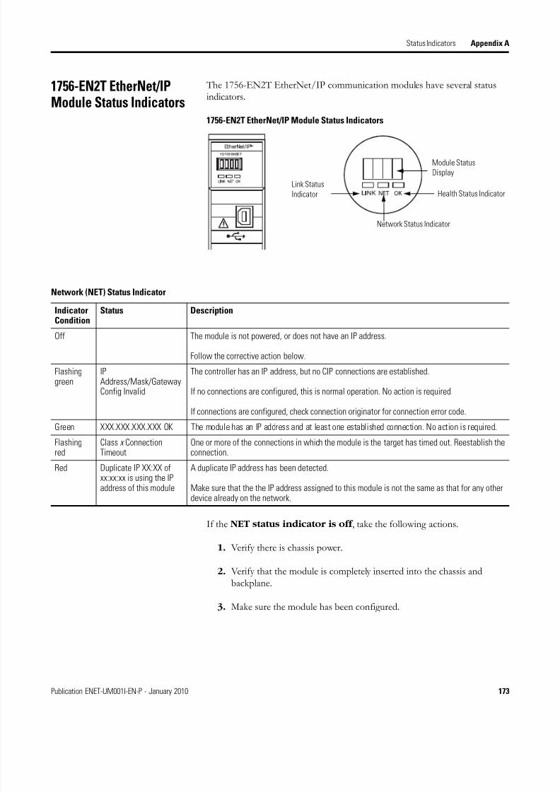
8/13/2019 EtherNet-IP Modules in Logix5000 Control Systems User Manual
http://slidepdf.com/reader/full/ethernet-ip-modules-in-logix5000-control-systems-user-manual 173/230
Publication ENET-UM001I-EN-P - January 2010 173
Status Indicators Appendix A
1756-EN2T EtherNet/IPModule Status Indicators
The 1756-EN2T EtherNet/IP communication modules have several statusindicators.
1756-EN2T EtherNet/IP Module Status Indicators
If the NET status indicator is off , take the following actions.
1. Verify there is chassis power.
2. Verify that the module is completely inserted into the chassis andbackplane.
3. Make sure the module has been configured.
Module Status
Display
Health Status Indicator
Network Status Indicator
Link Status
Indicator
Network (NET) Status Indicator
IndicatorCondition
Status Description
Off The module is not powered, or does not have an IP address.
Follow the corrective action below.
Flashinggreen
IPAddress/Mask/GatewayConfig Invalid
The controller has an IP address, but no CIP connections are established.
If no connections are configured, this is normal operation. No action is required.
If connections are configured, check connection originator for connection error code.
Green XXX.XXX.XXX.XXX OK The module has an IP address and at least one established connection. No action is required.
Flashingred
Class x ConnectionTimeout
One or more of the connections in which the module is the target has timed out. Reestablish theconnection.
Red Duplicate IP XX:XX ofxx:xx:xx is using the IPaddress of this module
A duplicate IP address has been detected.
Make sure that the the IP address assigned to this module is not the same as that for any otherdevice already on the network.

8/13/2019 EtherNet-IP Modules in Logix5000 Control Systems User Manual
http://slidepdf.com/reader/full/ethernet-ip-modules-in-logix5000-control-systems-user-manual 174/230
174 Publication ENET-UM001I-EN-P - January 2010
Appendix A Status Indicators
If the OK status indicator is off , take the following actions.
1. Verify that there is chassis power.
2. Verify that the module is completely inserted into the chassis andbackplane.
If the OK status indicator is red , take the following actions.
1. Cycle power to the module.
2. If this does not clear the fault, replace the module.
Link Status Indicator
Indicator
Condition
Status Description
Off Link lost No data is being transmitted. Check to see if any cables are disconnected.
Green XXX.XXX.XXX.XXX OK The module is ready to communicate. No action is required.
Flashinggreen
Data transmission is in progress. No action is required.
OK Status Indicator
IndicatorCondition
Status Description
Off The module does not have 24V DC power.
Follow the corrective action below.
Flashinggreen
BOOTP - XX:XX:XX:XX:XX:XX orxx:xx:xx:xx:xx:xxDHCP - XX:XX:XX:XX:XX:XX
The module is not configured. Configure the module.
Green XXX.XXX.XXX.XXX OK The module is operating correctly. No action is required.
Flashingred
Duplicate IP XX:XX:XX:XX:XX:XX A device with the Ethernet MAC address of xx:xx:xx:xx:xx:xx is using the IP address ofthis module.
Make sure that the the IP address assigned to this module is not identical to that of any
other device already on the network.Flash Update A firmware update is in progress. No action is required.
Red Severe Fault An unrecoverable fault has been detected.
Follow the corrective action below.
Flashingred/green
Rev %d.%d.%d The module is performing a self test while it is being started. No action is required.
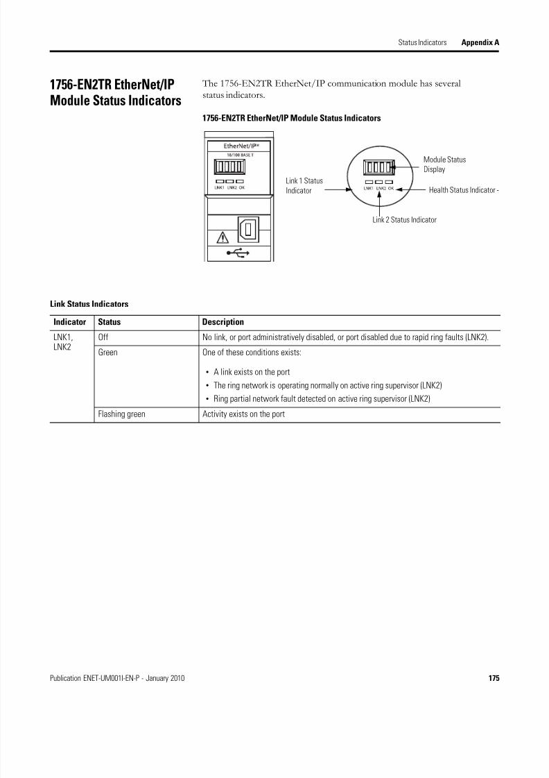
8/13/2019 EtherNet-IP Modules in Logix5000 Control Systems User Manual
http://slidepdf.com/reader/full/ethernet-ip-modules-in-logix5000-control-systems-user-manual 175/230
Publication ENET-UM001I-EN-P - January 2010 175
Status Indicators Appendix A
1756-EN2TR EtherNet/IPModule Status Indicators
The 1756-EN2TR EtherNet/IP communication module has severalstatus indicators.
1756-EN2TR EtherNet/IP Module Status Indicators
Module Status
Display
Health Status Indicator -
Link 2 Status Indicator
Link 1 Status
Indicator
Link Status Indicators
Indicator Status Description
LNK1, LNK2
Off No link, or port administratively disabled, or port disabled due to rapid ring faults (LNK2).
Green One of these conditions exists:
• A link exists on the port
• The ring network is operating normally on active ring supervisor (LNK2)
• Ring partial network fault detected on active ring supervisor (LNK2)
Flashing green Activity exists on the port

8/13/2019 EtherNet-IP Modules in Logix5000 Control Systems User Manual
http://slidepdf.com/reader/full/ethernet-ip-modules-in-logix5000-control-systems-user-manual 176/230
176 Publication ENET-UM001I-EN-P - January 2010
Appendix A Status Indicators
If the OK status indicator Red and alphanumeric display scrolls'Image Update Needed', take the following actions.
1. Update the firmware image.
2. Once the image is updated, recycle power.
3. If this does not clear the fault, replace the module.
OK Status Indicator
OK Off Module does not have 24V DC power. Verify that there is chassis power and the module is
completely inserted into chassis and backplane.Flashing green Module is not configured.
Green Module is operating correctly.
Flashing red Module detected a recoverable fault. A configuration error may have caused the fault.
Red Recycle power to the module. If this does not clear the fault, replace the module. Check themodule configuration and, if necessary, reconfigure the module.
Red and alphanumeric displayscrolls 'Image UpdateNeeded'
The main firmware image needs to be updated. Follow the corrective action below.
Flashing red and green Module performing power-up self-test. Wait for the module to complete powering up andperforming self-test.

8/13/2019 EtherNet-IP Modules in Logix5000 Control Systems User Manual
http://slidepdf.com/reader/full/ethernet-ip-modules-in-logix5000-control-systems-user-manual 177/230
Publication ENET-UM001I-EN-P - January 2010 177
Status Indicators Appendix A
1756-EN2TXTControlLogix-XTEtherNet/IP Bridge Module
Status Indicators
The 1756-EN2TXT EtherNet/IP communication module has severalstatus indicators.
1756-EN2TXT EtherNet/IP Module Status Indicators
Module Status
Display
Health Status Indicator -
Link 2 Status Indicator
Link 1 Status
Indicator
NET Status Indicators
Indicator Status Description
Link Off The module is not ready to communicate. Verify that the module is on.
Green The module is ready to communicate.
Flashing green The module is communicating over the network.
NET Status Indicators
Indicator Status Description
NET Off The module is not powered. Verify that there is chassis power and that the module iscompletely inserted into the chassis and backplane.
The module does not have a valid IP address. Make sure the module has been configuredwith a valid IP address.
Green The module has an IP address and at least one established connection.
Flashing green The module has an IP address, but has no established connections.
Red The module is attempting to use an IP address already in use on the network. Assign a
unique IP address to the module.
Flashing red One or more of the connections in which the module is the target has timed out.
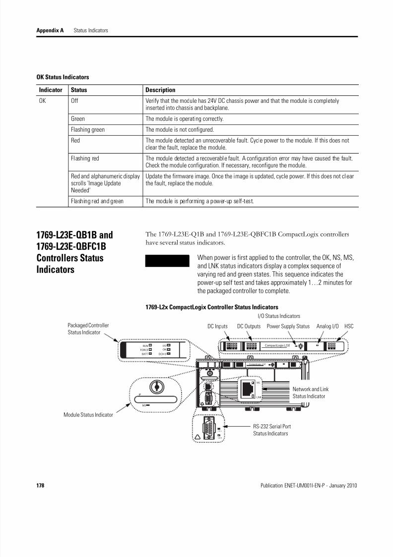
8/13/2019 EtherNet-IP Modules in Logix5000 Control Systems User Manual
http://slidepdf.com/reader/full/ethernet-ip-modules-in-logix5000-control-systems-user-manual 178/230
178 Publication ENET-UM001I-EN-P - January 2010
Appendix A Status Indicators
1769-L23E-QB1B and1769-L23E-QBFC1BControllers StatusIndicators
The 1769-L23E-Q1B and 1769-L23E-QBFC1B CompactLogix controllershave several status indicators.
1769-L2x CompactLogix Controller Status Indicators
OK Status Indicators
Indicator Status Description
OK Off Verify that the module has 24V DC chassis power and that the module is completelyinserted into chassis and backplane.
Green The module is operating correctly.
Flashing green The module is not configured.
Red The module detected an unrecoverable fault. Cycle power to the module. If this does notclear the fault, replace the module.
Flashing red The module detected a recoverable fault. A configuration error may have caused the fault.Check the module configuration. If necessary, reconfigure the module.
Red and alphanumeric displayscrolls 'Image UpdateNeeded'
Update the firmware image. Once the image is updated, cycle power. If this does not clearthe fault, replace the module.
Flashing red and green The module is performing a power-up self-test.
TIP When power is first applied to the controller, the OK, NS, MS,and LNK status indicators display a complex sequence ofvarying red and green states. This sequence indicates thepower-up self test and takes approximately 1…2 minutes for
the packaged controller to complete.
CompactLogix L23E
I/O
DCH 0
FORCE
RUN
BATT
OK
MS
IP
CH 1
CH 0
CompactLogix L23E
NS
LNK
Packaged Controller
Status Indicator
Module Status Indicator
Network and LinkStatus Indicator
RS-232 Serial Port
Status Indicators
I/O Status Indicators
DC Inputs DC Outputs Power Supply Status Analog I/O HSC

8/13/2019 EtherNet-IP Modules in Logix5000 Control Systems User Manual
http://slidepdf.com/reader/full/ethernet-ip-modules-in-logix5000-control-systems-user-manual 179/230
Publication ENET-UM001I-EN-P - January 2010 179
Status Indicators Appendix A
Packaged Controller Status Indicators
Indicator Status Description
RUN Off The packaged controller is in program or test mode.
Steady green The packaged controller is in run mode.
FORCE Off Either:
• No tags contain I/O force values.
• I/O forces are inactive (disabled).
Steady amber Either:
• I/O forces are active (enabled).
• I/O forces values may or may not exist.
Flashing amber One or more input or output addresses have been forced to an On or Offcondition, but the forces have not been enabled.
BATT Off The battery supports memory.
Steady red The battery is either:
• not installed.
• 95% dischared and should be replaced.
I/O Off Either:
• There are no devices in the I/O configuration of the packaged controller.
• The packaged controller does not contain a project.
Steady green The packaged controller is communicating with all the devices in its I/Oconfiguration.
Flashing green One or more devices in the I/O configuration of the packaged controller are notresponding.
Flashing red Either:
• The packaged controller is not communicating with any devices.
• The packaged controller is faulted.
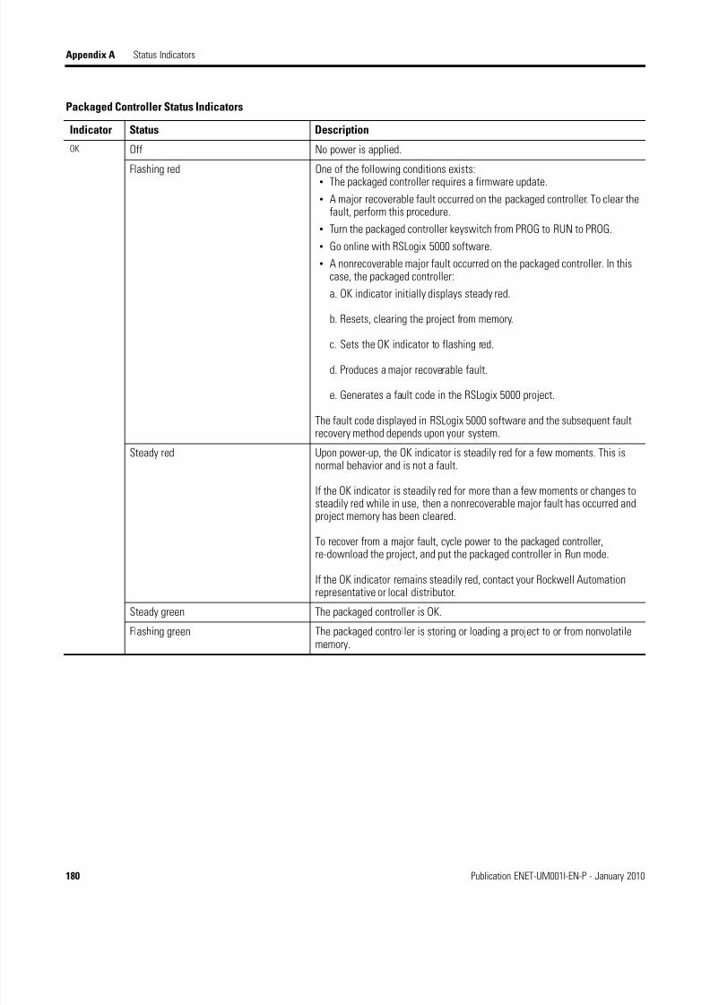
8/13/2019 EtherNet-IP Modules in Logix5000 Control Systems User Manual
http://slidepdf.com/reader/full/ethernet-ip-modules-in-logix5000-control-systems-user-manual 180/230
180 Publication ENET-UM001I-EN-P - January 2010
Appendix A Status Indicators
OK Off No power is applied.
Flashing red One of the following conditions exists:• The packaged controller requires a firmware update.
• A major recoverable fault occurred on the packaged controller. To clear thefault, perform this procedure.
• Turn the packaged controller keyswitch from PROG to RUN to PROG.
• Go online with RSLogix 5000 software.
• A nonrecoverable major fault occurred on the packaged controller. In thiscase, the packaged controller:
a. OK indicator initially displays steady red.
b. Resets, clearing the project from memory.
c. Sets the OK indicator to flashing red.
d. Produces a major recoverable fault.
e. Generates a fault code in the RSLogix 5000 project.
The fault code displayed in RSLogix 5000 software and the subsequent faultrecovery method depends upon your system.
Steady red Upon power-up, the OK indicator is steadily red for a few moments. This isnormal behavior and is not a fault.
If the OK indicator is steadily red for more than a few moments or changes tosteadily red while in use, then a nonrecoverable major fault has occurred andproject memory has been cleared.
To recover from a major fault, cycle power to the packaged controller,re-download the project, and put the packaged controller in Run mode.
If the OK indicator remains steadily red, contact your Rockwell Automationrepresentative or local distributor.
Steady green The packaged controller is OK.
Flashing green The packaged controller is storing or loading a project to or from nonvolatilememory.
Packaged Controller Status Indicators
Indicator Status Description

8/13/2019 EtherNet-IP Modules in Logix5000 Control Systems User Manual
http://slidepdf.com/reader/full/ethernet-ip-modules-in-logix5000-control-systems-user-manual 181/230
Publication ENET-UM001I-EN-P - January 2010 181
Status Indicators Appendix A
MS Off The packaged controller does not have power. Check the controller powersupply.
Flashing green The port is in standby mode; it does not have an IP address and is operating inBOOTP mode. Verify that the BOOTP server is running.
Steady green The port is operating correctly. No action is required.
Steady red The packaged controller is holding the port in reset or the packaged controllerhas faulted. Clear the fault. If the fault will not clear, replace the packagedcontroller.
The port is performing its power-up self test. No action is required.
A non-recoverable fault has occurred. Cycle power to the controller. If the faultwill not clear, replace the packaged controller.
Flashing red The port firmware is being uploaded. No action is required.
NET Off The port is not initialized; it does not have an IP address and is operating inBOOTP mode. Verify that the BOOTP server is running.
Flashing green The port has an IP address, but no CIP connections are established.
If no connections are configured, no action is required.
If connections are configured, check connection originator for connection errorcode.
Steady green The port has an IP address and CIP connections (Class 1 or Class 3) areestablished. No action is required.
Steady red Duplicate IP adddress has been detected. Verify that all IP addresses areunique.
Flashing red/green The port is performing its power-up self test. No action is required.
LNK Off The port is not connected to a powered Ethernet device. Therefore, thecontroller cannot communicate over an Ethernet network.
Verify that all Ethernet cables are connected.
Verify that Ethernet switch is powered.
Flashing green The port is performing its power-up self test. No action required.
The port is communicating on Ethernet. No action required.
Steady green The port is connected to a powered Ethernet device. Therefore, the controllercan communicate over an Ethernet network. No action required.
CH0 Off Channel 0 configuration differs from the default serial configuration.
Steady green Channel 0 has the default serial configuration.
CH1 Off No RS-232 activity.
Flashing green RS-232 activity.
Packaged Controller Status Indicators
Indicator Status Description
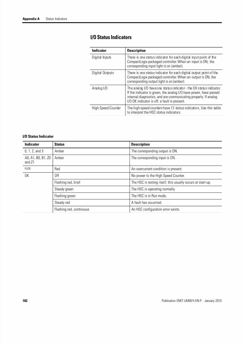
8/13/2019 EtherNet-IP Modules in Logix5000 Control Systems User Manual
http://slidepdf.com/reader/full/ethernet-ip-modules-in-logix5000-control-systems-user-manual 182/230
182 Publication ENET-UM001I-EN-P - January 2010
Appendix A Status Indicators
I/O Status Indicators
Indicator Description
Digital Inputs There is one status indicator for each digital input point of the
CompactLogix packaged controller. When an input is ON, thecorresponding input light is on (amber).
Digital Outputs There is one status indicator for each digital output point of theCompactLogix packaged controller. When an output is ON, thecorresponding output light is on (amber).
Analog I/O The analog I/O have one status indicator - the OK status indicator.If the indicator is green, the analog I/O have power, have passedinternal diagnostics, and are communicating properly. If analogI/O OK indicator is off, a fault is present.
High Speed Counter The high-speed counters have 12 status indicators. Use this tableto interpret the HSC status indicators.
I/O Status Indicator
Indicator Status Description
0, 1, 2, and 3 Amber The corresponding output is ON.
A0, A1, B0, B1, Z0and Z1
Amber The corresponding input is ON.
FUSE Red An overcurrent condition is present.
OK Off No power to the High Speed Counter.
Flashing red, brief The HSC is testing itself; this usually occurs at start-up.
Steady green The HSC is operating normally.
Flashing green The HSC is in Run mode.
Steady red A fault has occurrred.
Flashing red, continuous An HSC configuration error exists.

8/13/2019 EtherNet-IP Modules in Logix5000 Control Systems User Manual
http://slidepdf.com/reader/full/ethernet-ip-modules-in-logix5000-control-systems-user-manual 183/230
Publication ENET-UM001I-EN-P - January 2010 183
Status Indicators Appendix A
1769-L32E and 1769-L35EControllers StatusIndicators
The 1769-L32E and 1769-L35E CompactLogix controllers have several statusindicators.
1769-L3xx CompactLogix Controller Status Indicators
Module Status (MS) Indicator
Network Status (NS) Indicator
Health Status Indicator (LNK)
Status Indicators
Indicator Status Description
MS Off The controller has no power. Check the controller power supply.
Flashing green The controller does not have an IP address and is operating in BOOTP mode.Verify that the BOOTP server is running.
Green The controller is operating correctly. No action is required.
Red The controller is holding the port in reset orthe controller is faulted. Follow thecorrective action below.
The controller is performing a self test while it is being started. No action isrequired.
An unrecoverable fault has occurred. Follow the corrective action below.
Flashing red A duplicate IP address has been detected. Make sure that the the IP addressassigned to this module is not identical to that of any other device already onthe network.
The controller firmware is being updated. No action is required.
NS Off The controller does not have an IP address and is operating in BOOTP mode.Verify that the BOOTP server is running.
Flashing green The controller has an IP address, but no CIP connections are established.Follow the corrective action below.
Green The controller has an IP address and CIP connections (Class 1 or Class 3) areestablished. No action is required.
Red A duplicate IP address has been detected. Make sure that the IP addressassigned to this module is not the same as that for any other device already onthe network.
Flashing red/green The controller is performing a self test while it is being started. No action isrequired.

8/13/2019 EtherNet-IP Modules in Logix5000 Control Systems User Manual
http://slidepdf.com/reader/full/ethernet-ip-modules-in-logix5000-control-systems-user-manual 184/230
184 Publication ENET-UM001I-EN-P - January 2010
Appendix A Status Indicators
If the MS status indicator is red , take the following actions.
1. Clear the controller fault or cycle power to the controller.
2. If the fault will not clear, replace the controller.
If the NS status indicator is flashing green , take the following actions.
1. If no connections are configured, this is normal, and no action isrequired.
2. If connections are configured, check connection originator forconnection error code.
If the LNK status indicator is green , take the following actions.
1. Verify that all Ethernet cables are connected.
2. Verify that Ethernet switch is powered.
LNK Off The port is not connected to a powered Ethernet device. The controller cannotcommunicate over an Ethernet network. Follow the corrective action below.
Flashing green The controller is performing a self test while it is being started. No action isrequired.
The controller is communicating on an Ethernet network. No action is required.
Green The port is connected to a powered Ethernet device. The controller cancommunicate over an Ethernet network. No action is required.
Status Indicators
Indicator Status Description

8/13/2019 EtherNet-IP Modules in Logix5000 Control Systems User Manual
http://slidepdf.com/reader/full/ethernet-ip-modules-in-logix5000-control-systems-user-manual 185/230
Publication ENET-UM001I-EN-P - January 2010 185
Status Indicators Appendix A
1768-ENBT ModuleStatus Indicators
The 1768-ENBT CompactLogix EtherNet/IP communication module hasseveral status indicators.
1768-ENBT EtherNet/IP Module Status Indicators
If the NET status indicator is off , take the following actions.
1. Verify there is chassis power.
2. Verify that the module is completely inserted into the chassis andbackplane.
3. Make sure the module has been configured.
LINK NET OK
LINK NET OK
Module Status
Display
Network Status Indicator
Link Status
Indicator Health Status Indicator
Network (NET) Status Indicator
IndicatorCondition
Status Description
Off The module is not powered, or does not have an IP address.
Follow the corrective action below.
Flashinggreen
Controller Comm Problem The controller has an IP address, but no CIP connections are established.
If no connections are configured, this is normal operation. No action isrequired.
If connections are configured, check the connection originator for a connectionerror code.
Green XXX.XXX.XXX.XXX OK The module has an IP address and at least one established connection. Noaction is required.
Flashing red Class x Connection Timeout One or more of the connections in which the module is the target has timedout. Reestablish the connection.
Red Duplicate IP XX:XX of xx:xx:xx is using theIP address of this module
A duplicate IP address has been detected.
Make sure that the the IP address assigned to this module is not identical tothat of any other device already on the network.

8/13/2019 EtherNet-IP Modules in Logix5000 Control Systems User Manual
http://slidepdf.com/reader/full/ethernet-ip-modules-in-logix5000-control-systems-user-manual 186/230
186 Publication ENET-UM001I-EN-P - January 2010
Appendix A Status Indicators
If the OK status indicator is off , take the following actions.
1. Verify there is power.
2. Verify that the module is properly installed.
Link Status Indicator
Indicator
Condition
Status Description
Off Link lost No data is being transmitted. Check to see if any cables are disconnected.
Green XXX.XXX.XXX.XXX OK The module is ready to communicate. No action is required.
Flashinggreen
Data is being transmitted. The module is communicating over the network. Noaction is required.
OK Status Indicator
IndicatorCondition
Status Description
Off The module does not have 5V DC power.
Follow the corrective action below.
FlashingGreen
BOOTP - XX:XX:XX:XX:XX:XX orxx:xx:xx:xx:xx:xx
DHCP - XX:XX:XX:XX:XX:XX
The module is not configured. Configure the module
Green XXX.XXX.XXX.XXX OK The module is operating correctly. No action is required.
Flashing red Duplicate IP XX:XX:XX:XX:XX:XX A device with the Ethernet MAC address of xx:xx:xx:xx:xx:xx is using the IPaddress of this module.
Make sure that the the IP address assigned to this module is not identical tothat of any other device already on the network.
Flash Update A firmware update is in progress. No action is required.
Flashing Redand Green
Rev %d.%d.%d The module is performing a self test while it is being started. No action isrequired.

8/13/2019 EtherNet-IP Modules in Logix5000 Control Systems User Manual
http://slidepdf.com/reader/full/ethernet-ip-modules-in-logix5000-control-systems-user-manual 187/230
Publication ENET-UM001I-EN-P - January 2010 187
Status Indicators Appendix A
1783-ETAP, 1783-ETAP1F,and 1783-ETAP2FEtherNet/IP Tap Status
Indicators
The 1783-ETAP, 1783-ETAP1F, and 1783-ETAP2F EtherNet/IP taps haveseveral status indicators.
1783-ETAP EtherNet/IP Tap Status Indicators
OK Status
Indicator
Link 1 & 2
Status
Indicators
Device Port
Status
Indicators
OK Status Indicator
Indicator Status Description
OK Off Tap is not powered
Flashing green Tap is not configured
Solid green Tap is powered, configured, and operating correctly
Flashing red One of the following:
• Recoverable fault detected, such as duplicate IP address
• Flash update in progress is detected
Solid red Unrecoverable fault detected
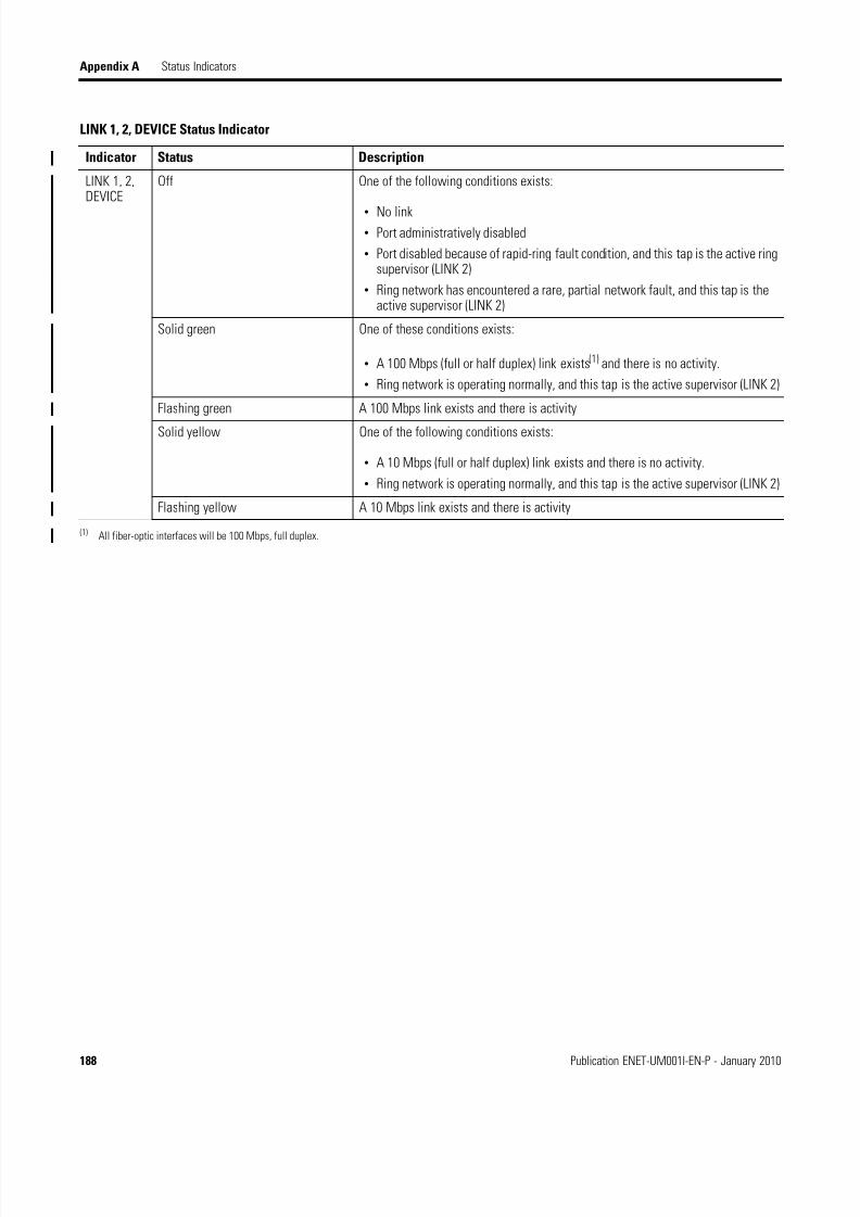
8/13/2019 EtherNet-IP Modules in Logix5000 Control Systems User Manual
http://slidepdf.com/reader/full/ethernet-ip-modules-in-logix5000-control-systems-user-manual 188/230
188 Publication ENET-UM001I-EN-P - January 2010
Appendix A Status Indicators
LINK 1, 2, DEVICE Status Indicator
Indicator Status Description
LINK 1, 2,DEVICE
Off One of the following conditions exists:
• No link• Port administratively disabled
• Port disabled because of rapid-ring fault condition, and this tap is the active ringsupervisor (LINK 2)
• Ring network has encountered a rare, partial network fault, and this tap is theactive supervisor (LINK 2)
Solid green One of these conditions exists:
• A 100 Mbps (full or half duplex) link exists(1) and there is no activity.
• Ring network is operating normally, and this tap is the active supervisor (LINK 2)
Flashing green A 100 Mbps link exists and there is activity
Solid yellow One of the following conditions exists:
• A 10 Mbps (full or half duplex) link exists and there is no activity.
• Ring network is operating normally, and this tap is the active supervisor (LINK 2)
Flashing yellow A 10 Mbps link exists and there is activity
(1) All fiber-optic interfaces will be 100 Mbps, full duplex.

8/13/2019 EtherNet-IP Modules in Logix5000 Control Systems User Manual
http://slidepdf.com/reader/full/ethernet-ip-modules-in-logix5000-control-systems-user-manual 189/230
Publication ENET-UM001I-EN-P - January 2010 189
Status Indicators Appendix A
1788-ENBT EtherNet/IPDaughtercard StatusIndicators
The 1788-ENBT EtherNet/IP communication daughtercard has several statusindicators.
1788-ENBT EtherNet/IP Daughtercard Status Indicators
IMPORTANT The 1788-ENBT card does not display any scrolling messages.
M
S
N
S
LNK U%
Module Status
Indicator
Network Status
Indicator
Link Status
Indicator
Utilization Percent Indicator
Status Indicator
Indicator Status Description
MS Off The daughtercard has no power.
Follow the corrective action below.
Flashing green The daughtercard does not have an IP address and is operating in BOOTPmode. Verify that the BOOTP server is running.
Green The daughtercard is operating correctly. No action required.
Red The host is holding the daughtercard in reset or the host is faulted.
Follow the corrective action below.
The daughtercard is performing a self test while it is being started. No actionis required.
An unrecoverable fault has occurred.
Follow the corrective action below.
Flashing red A duplicate IP address has been detected. Make sure that the the IP addressassigned to this module is not identical to that of any other device already onthe network.
The daughtercard firmware is being updated. No action is required.
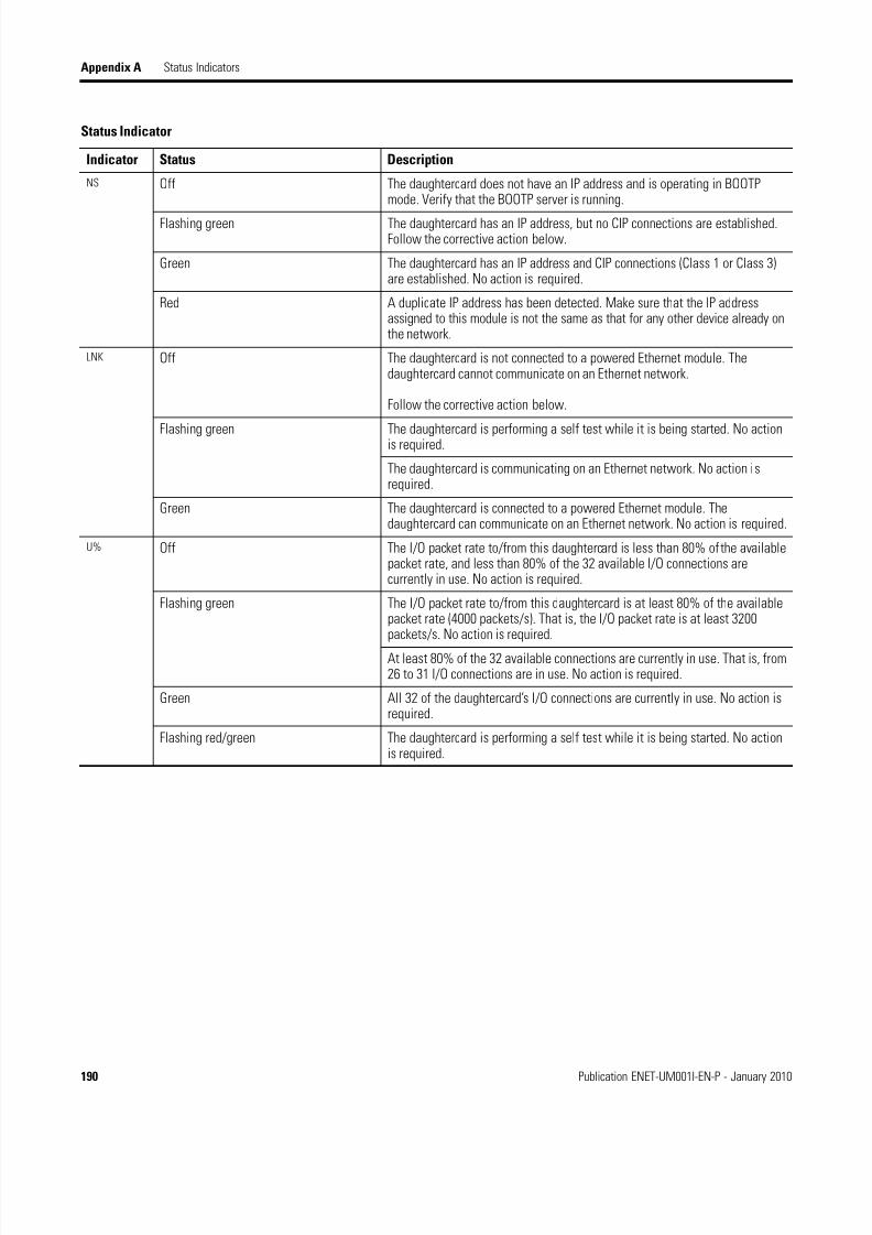
8/13/2019 EtherNet-IP Modules in Logix5000 Control Systems User Manual
http://slidepdf.com/reader/full/ethernet-ip-modules-in-logix5000-control-systems-user-manual 190/230
190 Publication ENET-UM001I-EN-P - January 2010
Appendix A Status Indicators
NS Off The daughtercard does not have an IP address and is operating in BOOTPmode. Verify that the BOOTP server is running.
Flashing green The daughtercard has an IP address, but no CIP connections are established.Follow the corrective action below.
Green The daughtercard has an IP address and CIP connections (Class 1 or Class 3)are established. No action is required.
Red A duplicate IP address has been detected. Make sure that the IP addressassigned to this module is not the same as that for any other device already onthe network.
LNK Off The daughtercard is not connected to a powered Ethernet module. Thedaughtercard cannot communicate on an Ethernet network.
Follow the corrective action below.
Flashing green The daughtercard is performing a self test while it is being started. No actionis required.
The daughtercard is communicating on an Ethernet network. No action isrequired.
Green The daughtercard is connected to a powered Ethernet module. Thedaughtercard can communicate on an Ethernet network. No action is required.
U% Off The I/O packet rate to/from this daughtercard is less than 80% of the availablepacket rate, and less than 80% of the 32 available I/O connections arecurrently in use. No action is required.
Flashing green The I/O packet rate to/from this daughtercard is at least 80% of the availablepacket rate (4000 packets/s). That is, the I/O packet rate is at least 3200packets/s. No action is required.
At least 80% of the 32 available connections are currently in use. That is, from26 to 31 I/O connections are in use. No action is required.
Green All 32 of the daughtercard’s I/O connections are currently in use. No action isrequired.
Flashing red/green The daughtercard is performing a self test while it is being started. No actionis required.
Status Indicator
Indicator Status Description

8/13/2019 EtherNet-IP Modules in Logix5000 Control Systems User Manual
http://slidepdf.com/reader/full/ethernet-ip-modules-in-logix5000-control-systems-user-manual 191/230
Publication ENET-UM001I-EN-P - January 2010 191
Status Indicators Appendix A
If the MS indicator is off , take the following actions.
1. Check the host power supply.
2. Verify that the daughtercard is firmly seated in the host’s slot.
3. Replace daughtercard or host.
If the MS indicator is red and the host is holding thedaughtercard in reset or the host is faulted , take the followingactions.
1. Verify that the daughtercard is firmly seated in the host’s slot.
2. Clear the host’s fault.
3. Replace daughtercard or host.
If the MS indicator is red and an unrecoverable fault hasoccurred , take the following actions.
1. Cycle power to the host.
2. Replace the daughtercard or host.
If the NS status indicator is flashing green , take the following actions.
1. If no connections are configured, this is normal operation.
No action is required.
2. If connections are configured, check connection originator forconnection error code.
If the LNK status indicator is off , take the following actions.
1. Verify that all Ethernet cables are connected.
2. Verify that the Ethernet switch is powered.

8/13/2019 EtherNet-IP Modules in Logix5000 Control Systems User Manual
http://slidepdf.com/reader/full/ethernet-ip-modules-in-logix5000-control-systems-user-manual 192/230
192 Publication ENET-UM001I-EN-P - January 2010
Appendix A Status Indicators
1734-AENT and 1734-AENTREtherNet/IP POINT I/OAdapter Status Indicators
The 1734-AENT and 1734-AENTR EtherNet/IP POINT I/O adapters haveseveral status indicators.
1734-AENT EtherNet/IP POINT I/O Adapter Status Indicators
IMPORTANT The 1734-AENT and 1734-AENTR adapters do not display any
scrolling messages.
Module Status Indicator
Network Activity Status
Network Status Indicator
POINTBus Status IndicatorSystem Power
Status Indicator
Field Power Status Indicator
Module Status Indicator
Indicator Status Description
ModuleStatus
Off No power is being applied to device. Apply power to the device.
Flashing Red/Green Status indicator cycle power test (module self-test) is being conducted. Noaction is required.
Solid Green The device is operating normally. No action is required.
Flashing Red Firmware (NVS) is being updated or the address switches have changed.
Follow the corrective action below.
Solid Red Self-test failure is present (checksum failure, or ramtest failure at cyclepower); firmware fatal error is present. Replace the adapter.
NetworkActivityStatus
Off No link exists. Verify network cabling, and correct, if necessary.
Flashing Green/Off I/O is being transmitted or received. No action is required.
Steady Green A link exists. No action is required.

8/13/2019 EtherNet-IP Modules in Logix5000 Control Systems User Manual
http://slidepdf.com/reader/full/ethernet-ip-modules-in-logix5000-control-systems-user-manual 193/230
Publication ENET-UM001I-EN-P - January 2010 193
Status Indicators Appendix A
NetworkStatus
Off The module has no IP address.
Follow the corrective action below.Flashing Green The module has an IP address, but no CIP connections. No action is required.
Solid Green The module is online and has an IP address and CIP connections. No action isrequired.
Flashing Red One or more CIP connections have timed out. Check for I/O module failure andcontroller operation, and correct, if necessary.
Solid Red A duplicate IP address has been detected. Verify IP address setting and correct,if necessary.
Flashing Red/Green The module is performing a normal self-test, which only occurs during thecycle-power test. No action is required.
POINTBus
Status
Off Power has not been applied to the device.
Follow the corrective action below.
Flashing Red/Green Status indicator cycle-power test is being performed. No action is required.
Flashing Red • When power is cycled, the number of expected modules does not equal thenumber of modules present.
• A module is missing.
• A node fault (I/O connection timeout) occurred.
Follow the corrective action below.
Solid Red The adapter is bus off. Follow the corrective action below.
Flashing Green A firmware (NVS) update is in progress. No action is required.
Solid Green An adapter is online with connections established. No action is required.
SystemPowerStatus
Off Field power is off or a DC-DC converter problem exists.
Follow the corrective action below.
Green DC-DC converter is active (5V). No action is required.
Field PowerStatus
Off Field power is off. Apply field power.
Green 24V power is present. No action is required.
Module Status Indicator
Indicator Status Description

8/13/2019 EtherNet-IP Modules in Logix5000 Control Systems User Manual
http://slidepdf.com/reader/full/ethernet-ip-modules-in-logix5000-control-systems-user-manual 194/230
194 Publication ENET-UM001I-EN-P - January 2010
Appendix A Status Indicators
If the Module status indicator is flashing red , take the followingactions.
1. Complete firmware update.
2. Verify address switches.
If the Network status indicator is off , take the following actions.
1. Apply power to device.
2. Verify, and correct, IP address, if necessary.
If the POINTBus status indicator is off , take the following actions.
1. Apply power to device
2. Check module status indicator.
If the POINTBus status indicator is flashing red , take the followingactions.
1. Configure the chassis size.
2. Check for missing module and reinstall, if necessary.
3. Check for I/O module failure and correct, if necessary.
If the POINTBus status indicator is solid red , take the followingactions.
1. Cycle power to device.
2. If condition persists, replace device.
If the System Power status indicator is off , take the following actions.
1. Verify that power is on, and apply power if needed.
2. Verify backplane power has not been exceeded, and correct.
3. Replace 1734-AENT module.
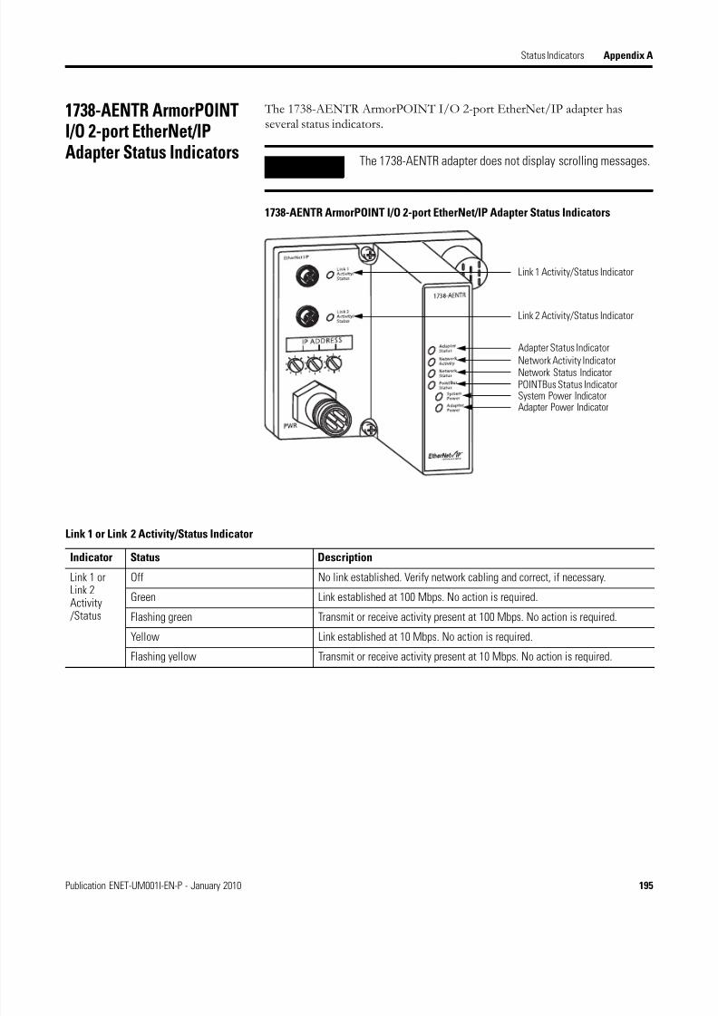
8/13/2019 EtherNet-IP Modules in Logix5000 Control Systems User Manual
http://slidepdf.com/reader/full/ethernet-ip-modules-in-logix5000-control-systems-user-manual 195/230
Publication ENET-UM001I-EN-P - January 2010 195
Status Indicators Appendix A
1738-AENTR ArmorPOINTI/O 2-port EtherNet/IPAdapter Status Indicators
The 1738-AENTR ArmorPOINT I/O 2-port EtherNet/IP adapter hasseveral status indicators.
1738-AENTR ArmorPOINT I/O 2-port EtherNet/IP Adapter Status Indicators
IMPORTANT The 1738-AENTR adapter does not display scrolling messages.
Link 1 Activity/Status Indicator
Link 2 Activity/Status Indicator
Adapter Status Indicator
Network Activity IndicatorNetwork Status IndicatorPOINTBus Status IndicatorSystem Power IndicatorAdapter Power Indicator
Link 1 or Link 2 Activity/Status Indicator
Indicator Status Description
Link 1 orLink 2Activity /Status
Off No link established. Verify network cabling and correct, if necessary.
Green Link established at 100 Mbps. No action is required.
Flashing green Transmit or receive activity present at 100 Mbps. No action is required.
Yellow Link established at 10 Mbps. No action is required.
Flashing yellow Transmit or receive activity present at 10 Mbps. No action is required.

8/13/2019 EtherNet-IP Modules in Logix5000 Control Systems User Manual
http://slidepdf.com/reader/full/ethernet-ip-modules-in-logix5000-control-systems-user-manual 196/230
196 Publication ENET-UM001I-EN-P - January 2010
Appendix A Status Indicators
Adapter Status Indicator
Indicator Status Description
AdapterStatus
Off No power applied to the adapter. Apply power to the adapter.
Green Adapter is operating properly. No action required.
Flashing red/green The adapter is in self-test mode. No action required.
Flashing red A recoverable fault has been detected due to the one of the followingconditions:
• A firmware (NVS) update is in process. Allow the process to complete.
• The address switches have been changed. Verify the address switches arecorrect.
Red An unrecoverable fault has been detected due to one of the following
conditions:
• A self-test failure
• A firmware fatal error
In both cases, you must replace the adapter.
Network Activity Status Indicator
Indicator Status Description
NetworkActivity Off No link established with Port 1 or Port 2. Verify network cabling and, ifnecessary, correct.
Green One of the following conditions has been detected:
• Link established with Port 1 and/or Port 2 at 100 Mbps
• Link established with Port 1 and Port 2. One link is at 100 Mbps and one at10 Mbps.
In either case, no action is required.
Flashing green One of the following conditions has been detected:
• Transmit or receive activity present on Port 1 and/or Port 2 at 100 Mbps.
• Transmit or receive activity present on Port 1 and/or Port 2. One port at 100Mbps and one port at 10 Mbps.
In either case, no action is required.
Yellow Link established with Port 1 and/or Port 2 at 10 Mbps. No action is required.
Flashing yellow Transmit or receive activity present on Port 1 and/or Port at 10 Mbps. No actionis required.
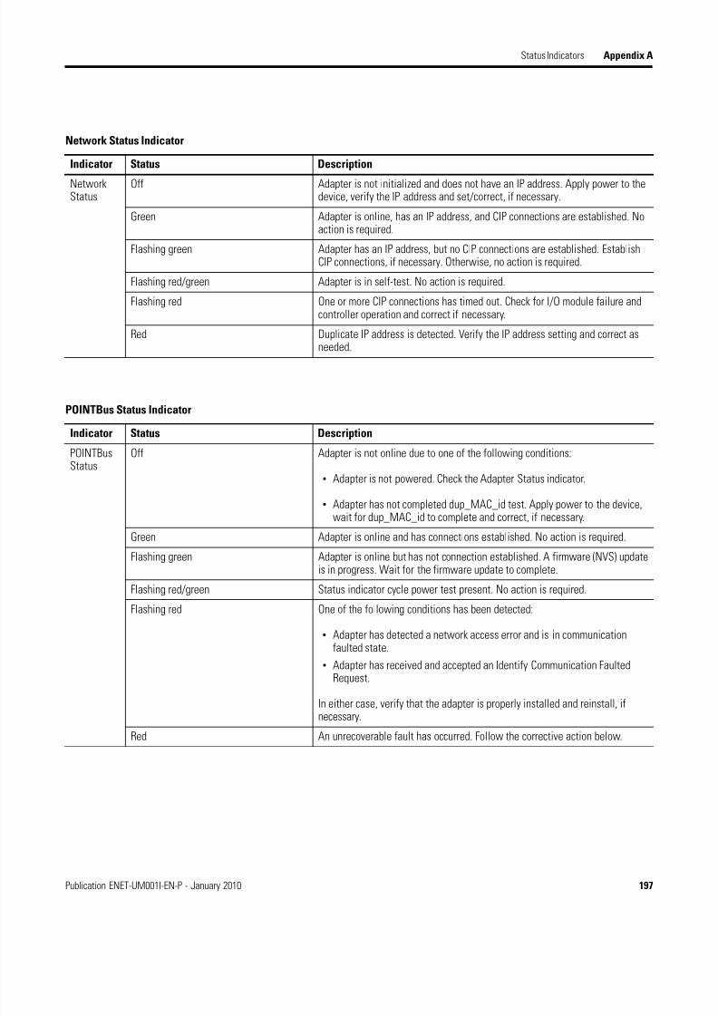
8/13/2019 EtherNet-IP Modules in Logix5000 Control Systems User Manual
http://slidepdf.com/reader/full/ethernet-ip-modules-in-logix5000-control-systems-user-manual 197/230
Publication ENET-UM001I-EN-P - January 2010 197
Status Indicators Appendix A
Network Status Indicator
Indicator Status Description
NetworkStatus
Off Adapter is not initialized and does not have an IP address. Apply power to thedevice, verify the IP address and set/correct, if necessary.
Green Adapter is online, has an IP address, and CIP connections are established. Noaction is required.
Flashing green Adapter has an IP address, but no CIP connections are established. EstablishCIP connections, if necessary. Otherwise, no action is required.
Flashing red/green Adapter is in self-test. No action is required.
Flashing red One or more CIP connections has timed out. Check for I/O module failure andcontroller operation and correct if necessary.
Red Duplicate IP address is detected. Verify the IP address setting and correct asneeded.
POINTBus Status Indicator
Indicator Status Description
POINTBusStatus
Off Adapter is not online due to one of the following conditions:
• Adapter is not powered. Check the Adapter Status indicator.
• Adapter has not completed dup_MAC_id test. Apply power to the device,wait for dup_MAC_id to complete and correct, if necessary.
Green Adapter is online and has connections established. No action is required.
Flashing green Adapter is online but has not connection established. A firmware (NVS) updateis in progress. Wait for the firmware update to complete.
Flashing red/green Status indicator cycle power test present. No action is required.
Flashing red One of the following conditions has been detected:
• Adapter has detected a network access error and is in communicationfaulted state.
• Adapter has received and accepted an Identify Communication FaultedRequest.
In either case, verify that the adapter is properly installed and reinstall, ifnecessary.
Red An unrecoverable fault has occurred. Follow the corrective action below.
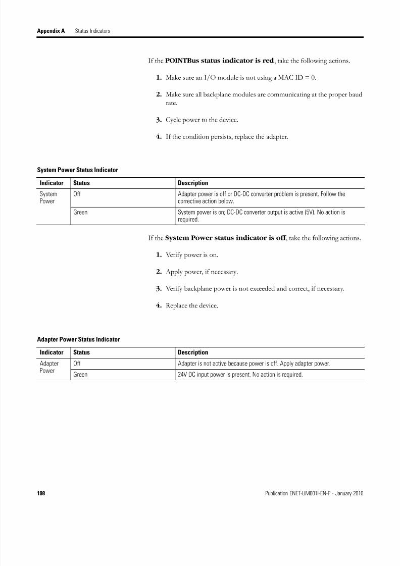
8/13/2019 EtherNet-IP Modules in Logix5000 Control Systems User Manual
http://slidepdf.com/reader/full/ethernet-ip-modules-in-logix5000-control-systems-user-manual 198/230
198 Publication ENET-UM001I-EN-P - January 2010
Appendix A Status Indicators
If the POINTBus status indicator is red , take the following actions.
1. Make sure an I/O module is not using a MAC ID = 0.
2. Make sure all backplane modules are communicating at the proper baudrate.
3. Cycle power to the device.
4. If the condition persists, replace the adapter.
If the System Power status indicator is off , take the following actions.
1. Verify power is on.
2. Apply power, if necessary.
3. Verify backplane power is not exceeded and correct, if necessary.
4. Replace the device.
System Power Status Indicator
Indicator Status Description
SystemPower
Off Adapter power is off or DC-DC converter problem is present. Follow thecorrective action below.
Green System power is on; DC-DC converter output is active (5V). No action isrequired.
Adapter Power Status Indicator
Indicator Status Description
AdapterPower
Off Adapter is not active because power is off. Apply adapter power.
Green 24V DC input power is present. No action is required.
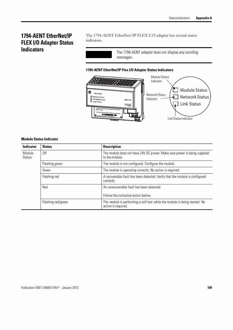
8/13/2019 EtherNet-IP Modules in Logix5000 Control Systems User Manual
http://slidepdf.com/reader/full/ethernet-ip-modules-in-logix5000-control-systems-user-manual 199/230
Publication ENET-UM001I-EN-P - January 2010 199
Status Indicators Appendix A
1794-AENT EtherNet/IPFLEX I/O Adapter StatusIndicators
The 1794-AENT EtherNet/IP FLEX I/O adapter has several statusindicators.
1794-AENT EtherNet/IP Flex I/O Adapter Status Indicators
IMPORTANT The 1794-AENT adapter does not display any scrolling
messages.
Module Status
Network Status
Link Status
Module Status
Indicator
Network Status
Indicator
Link Status Indicator
Module Status Indicator
Indicator Status Description
ModuleStatus
Off The module does not have 24V DC power. Make sure power is being suppliedto the module.
Flashing green The module is not configured. Configure the module.
Green The module is operating correctly. No action is required.
Flashing red A recoverable fault has been detected. Verify that the module is configuredcorrectly.
Red An unrecoverable fault has been detected.
Follow the corrective action below.
Flashing red/green The module is performing a self test while the module is being started. Noaction is required.

8/13/2019 EtherNet-IP Modules in Logix5000 Control Systems User Manual
http://slidepdf.com/reader/full/ethernet-ip-modules-in-logix5000-control-systems-user-manual 200/230
200 Publication ENET-UM001I-EN-P - January 2010
Appendix A Status Indicators
If the Module status indicator is red , take the following actions.
1. Recycle power to the module.
2. If this does not clear the fault, replace the module.
If the Network status indicator is off , take the following actions.
1. Verify there is power.
2. Verify that the module is correctly wired to the power supply.
3. Make sure the module is configured.
NetworkStatus
Off Power has not been applied to the module, or the module does not have an IPaddress.
Follow the corrective action below.
Flashing green The module has obtained an IP address, but has no established connections.
If no connections are configured, this is normal operation. No action isrequired.
If connections are configured, check connection originator for connection errorcode.
Green The module has an IP address and at least one established connection. Noaction is required.
Flashing red One or more of the connections in which the module is the target has timed
out. Reestablish the connection.Flashing red/green The module is performing a self test while it is being started. No action is
required.
Red Adapter has detected that its IP address is already in use. Configure theadapter with a unique IP address.
Link Status Off No data is being transmitted. No action is required.
Flashing green The module is ready to communicate. No action is required.
Green Data is being transmitted. No action is required.
Module Status Indicator
Indicator Status Description

8/13/2019 EtherNet-IP Modules in Logix5000 Control Systems User Manual
http://slidepdf.com/reader/full/ethernet-ip-modules-in-logix5000-control-systems-user-manual 201/230
Publication ENET-UM001I-EN-P - January 2010 201
Status Indicators Appendix A
20-COMM-E ModuleStatus Indicators
The 20-COMM-E module has four status indicators.
20-COMM-E Status Indicators
PORT - DPI Connection Status
MOD - Adapter Status
NET A - EtherNet/IP Connection Status
NET B - EtherNet/IP Transmit Status
Module Status Indicator
Indicator Status Description
PORT Off The adapter is not powered or is not properly connected to the drive.
Follow the corrective action below.
Flashing red The adapter is not receiving a ping message from the drive.
Follow the corrective action below.
Solid Red The drive has refused an I/O connection from the adapter. Another DPIperipheral is using the same DPI port as the adapter.
Another DPI peripheral is using the same DPI port as the adapter.
Follow the corrective action below.
Orange The adapter is connected to a product that does not support Allen-Bradley DPIcommunication.
Connect the adapter to a product that supports Allen-Bradley DPIcommunication (for example, a PowerFlex 7-Class drive).
Flashing Green The adapter is establishing an I/O connection to the drive. No action is
required.
Solid Green The adapter is properly connected and is communicating with the drive. Noaction is required.
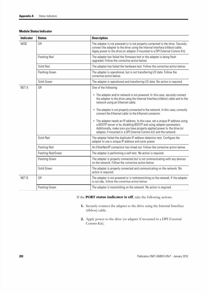
8/13/2019 EtherNet-IP Modules in Logix5000 Control Systems User Manual
http://slidepdf.com/reader/full/ethernet-ip-modules-in-logix5000-control-systems-user-manual 202/230
202 Publication ENET-UM001I-EN-P - January 2010
Appendix A Status Indicators
If the PORT status indicator is off , take the following actions.
1. Securely connect the adapter to the drive using the Internal Interface(ribbon) cable.
2. Apply power to the drive (or adapter if mounted in a DPI ExternalComms Kit).
MOD Off The adapter is not powered or is not properly connected to the drive. Securelyconnect the adapter to the drive using the Internal Interface (ribbon) cable.
Apply power to the drive (or adapter if mounted in a DPI External Comms Kit).Flashing Red The adapter has failed the firmware test or the adapter is being flash
upgraded. Follow the corrective action below.
Solid Red The adapter has failed the hardware test. Follow the corrective action below.
Flashing Green The adapter is operational, but is not transferring I/O data. Follow thecorrective action below.
Solid Green The adapter is operational and transferring I/O data. No action is required.
NET A Off One of the following:
• The adapter and/or network is not powered. In this case, securely connectthe adapter to the drive using the Internal Interface (ribbon) cable and to the
network using an Ethernet cable.
• The adapter is not properly connected to the network. In this case, correctlyconnect the Ethernet cable to the Ethernet connector.
• The adapter needs an IP address. In this case, set a unique IP address usinga BOOTP server or by disabling BOOTP and using adapter parameters.Additionally, make sure you have properly applied power to the drive (oradapter, if mounted in a DPI External Comms kit) and the network.
Solid Red The adapter failed the duplicate IP address detection test. Configure theadapter to use a unique IP address and cycle power.
Flashing Red An EtherNet/IP connection has timed out. Follow the corrective action below.
Flashing Red/Green The adapter is performing a self-test. No action is required.Flashing Green The adapter is properly connected but is not communicating with any devices
on the network. Follow the corrective action below.
Solid Green The adapter is properly connected and communicating on the network. Noaction is required.
NET B Off The adapter is not powered or is nottransmitting on the network. If the adapteris not idle, follow the corrective action below.
Flashing Green The adapter is transmitting on the network. No action is required.
Module Status Indicator
Indicator Status Description

8/13/2019 EtherNet-IP Modules in Logix5000 Control Systems User Manual
http://slidepdf.com/reader/full/ethernet-ip-modules-in-logix5000-control-systems-user-manual 203/230
Publication ENET-UM001I-EN-P - January 2010 203
Status Indicators Appendix A
If the PORT status indicator is flashing red , take the following actions.
1. Verify that cables are securely connected and not damaged; replacecables if necessary.
2. Cycle power to the drive (or adapter, if mounted in a DPI ExternalComms kit).
If the PORT status indicator is solid red , take any of the followingactions.
• Verify that all DPI cables on the drive are securely connected and notdamaged. Replace cables if necessary.
• Verify that the DPI drive supports Datalinks.
• Configure the adapter to use a Datalink that is not already being used byanother peripheral.
If the MOD status indicator is flashing red , take the following actions.
1. Clear faults in the adapter.
2. Cycle power to the drive (or adapter if mounted in a DPI ExternalComms Kit).
If cycling power does not correct the problem, the adapter parametersettings may have been corrupted.
3. Reset defaults and reconfigure the adapter.
4. If resetting defaults does not correct the problem, flash the adapter withthe latest firmware release.
If the MOD status indicator is solid red , take the following actions.
1. Cycle power to the drive (or adapter if mounted in a DPI ExternalComms Kit).
2. Replace the adapter.
If the MOD status indicator is flashing green , take the followingactions.
1. Place the scanner in RUN mode.
IMPORTANT Cycle power to the drive (or adapter if mounted in a DPIExternal Comms Kit) after making any of the followingcorrections.

8/13/2019 EtherNet-IP Modules in Logix5000 Control Systems User Manual
http://slidepdf.com/reader/full/ethernet-ip-modules-in-logix5000-control-systems-user-manual 204/230
204 Publication ENET-UM001I-EN-P - January 2010
Appendix A Status Indicators
2. Program the controller to recognize and transmit I/O to the adapter.
3. Configure the adapter for the program in the controller.
4. Normal behavior if no DPI I/O is enabled.
If the NET A status indicator is flashing red , take the following actions.
1. Place the scanner in RUN mode, or apply power to the peer device that will send I/O.
2. Check the amount of traffic on the network.
If the NET A status indicator is flashing green , take the followingactions.
1. Place the controller in RUN mode, or apply power to the peer devicethat will send I/O.
2. Program the controller or peer device to recognize and transmit I/O ormake a messaging connection to the adapter.
3. Configure the adapter for the program in the controller or the I/O fromthe peer device.
If the NET B status indicator is off and the NET A indicator is off ,take the following actions.
1. Securely connect the adapter to the drive using the Internal Interface(ribbon) cable and to the network using an Ethernet cable.
2. Correctly connect the Ethernet cable to the Ethernet connector.
3. Set a unique IP address using a BOOTP server or by disabling BOOTPand using adapter parameters.
If the NET B status indicator is off and the NET A indicator issolid red , configure the adapter to use a unique IP address and cycle power.
If the NET B status indicator is off and the NET A indicator is
flashing red/green or solid red , take the following actions.
1. Check the IP address in the adapter and scanner, and verify that thecontroller can communicate with the adapter.
2. Ping the adapter.

8/13/2019 EtherNet-IP Modules in Logix5000 Control Systems User Manual
http://slidepdf.com/reader/full/ethernet-ip-modules-in-logix5000-control-systems-user-manual 205/230
Publication ENET-UM001I-EN-P - January 2010 205
Status Indicators Appendix A
22-COMM-E ModuleStatus Indicators
The 22-COMM-E module has four status indicators.
22-COMM-E Status Indicators
PORT - DPI Connection Status
MOD - Adapter Status
NET A - EtherNet/IP Connection Status
NET B - EtherNet/IP Transmit Status
Module Status Indicator
Indicator Status Description
PORT Off The adapter is not powered or is not properly connected to the drive.
Follow the corrective action below.
Flashing Red In Single mode, the adapter is not receiving communication from the drive.
In Multi-Drive mode, the adapter is not receiving communication from a drive,or a drive is not an Allen-Bradley drive.
Follow the corrective action below.
Flashing Green The adapter is establishing communication with the drive. No action required.This status indicator will turn solid green or flashing red.
Solid Green The adapter is properly connected and is communicating with the drive. Noaction required.
Orange In Single mode, the drive is not an Allen-Bradley drive. Use an Allen-BradleyPowerFlex 40 drive.
MOD Off The adapter is not powered or is not properly connected to the drive. Follow thecorrective action below.
Flashing Red The adapter has failed the firmware test. Follow the corrective action below.
Solid Red The adapter has failed the hardware test. Follow the corrective action below.
Flashing Green The adapter is operational, but is not transferring I/O data. Follow thecorrective action below.
Solid Green The adapter is operational and transferring I/O data. Follow the correctiveaction below. No action is required.
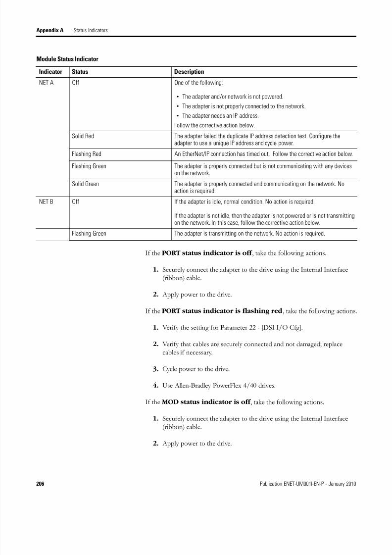
8/13/2019 EtherNet-IP Modules in Logix5000 Control Systems User Manual
http://slidepdf.com/reader/full/ethernet-ip-modules-in-logix5000-control-systems-user-manual 206/230
206 Publication ENET-UM001I-EN-P - January 2010
Appendix A Status Indicators
If the PORT status indicator is off , take the following actions.
1. Securely connect the adapter to the drive using the Internal Interface(ribbon) cable.
2. Apply power to the drive.
If the PORT status indicator is flashing red , take the following actions.
1. Verify the setting for Parameter 22 - [DSI I/O Cfg].
2. Verify that cables are securely connected and not damaged; replacecables if necessary.
3. Cycle power to the drive.
4. Use Allen-Bradley PowerFlex 4/40 drives.
If the MOD status indicator is off , take the following actions.
1. Securely connect the adapter to the drive using the Internal Interface(ribbon) cable.
2. Apply power to the drive.
NET A Off One of the following:
• The adapter and/or network is not powered.• The adapter is not properly connected to the network.
• The adapter needs an IP address.
Follow the corrective action below.
Solid Red The adapter failed the duplicate IP address detection test. Configure theadapter to use a unique IP address and cycle power.
Flashing Red An EtherNet/IP connection has timed out. Follow the corrective action below.
Flashing Green The adapter is properly connected but is not communicating with any deviceson the network.
Solid Green The adapter is properly connected and communicating on the network. Noaction is required.
NET B Off If the adapter is idle, normal condition. No action is required.
If the adapter is not idle, then the adapter is not powered or is not transmittingon the network. In this case, follow the corrective action below.
Flashing Green The adapter is transmitting on the network. No action is required.
Module Status Indicator
Indicator Status Description
8/13/2019 EtherNet-IP Modules in Logix5000 Control Systems User Manual
http://slidepdf.com/reader/full/ethernet-ip-modules-in-logix5000-control-systems-user-manual 207/230
Publication ENET-UM001I-EN-P - January 2010 207
Status Indicators Appendix A
If the MOD status indicator is flashing red , take the following actions.
1. Cycle power to the drive.
2. If cycling power does not correct the problem, the adapter parametersettings may have been corrupted. Reset defaults and reconfigure theadapter.
3. If resetting defaults does not correct the problem, flash the adapter withthe latest firmware release.
If the MOD status indicator is solid red , take the following actions.
1. Cycle power to the drive.
2. Replace the adapter.
If the MOD status indicator is flashing green , take the followingactions.
1. Place the scanner in RUN mode.
2. Program the controller to recognize and transmit I/O to the adapter.
3. Configure the adapter for the program in the controller.
4. Normal behavior if no DPI I/O is enabled.
If the NET A status indicator is off , take the following actions.
1. Securely connect the adapter to the drive using the Internal Interface(ribbon) cable and to the network using an Ethernet cable.
2. Correctly connect the Ethernet cable to the Ethernet connector.
3. Set a unique IP address using a BOOTP server or by disabling BOOTPand using adapter parameters.
4. Apply power to the drive (or adapter, if mounted in a DPI ExternalComms kit) and network.
If the NET A status indicator is flashing red , take the following actions.
1. Place the scanner in RUN mode.
2. Check the amount of traffic on the network.
If the NET A status indicator is flashing green, take the following actions.
1. Place the controller in RUN mode.

8/13/2019 EtherNet-IP Modules in Logix5000 Control Systems User Manual
http://slidepdf.com/reader/full/ethernet-ip-modules-in-logix5000-control-systems-user-manual 208/230
208 Publication ENET-UM001I-EN-P - January 2010
Appendix A Status Indicators
2. Program the controller or peer device to recognize and transmit I/O ormake a messaging connection to the adapter.
3. Configure the adapter for the program in the controller or the I/O fromthe peer device.
If the NET B status indicator is off and the NET A indicator is off ,take the following actions.
1. Securely connect the adapter to the drive using the Internal Interface(ribbon) cable and to the network using an Ethernet cable.
2. Correctly connect the Ethernet cable to the Ethernet connector.
3. Set a unique IP address using a BOOTP server or by disabling BOOTPand using adapter parameters.
If the NET B status indicator is off and the NET A indicator issolid red , take the following actions.
1. Configure the adapter to use a unique IP address.
2. Cycle power to the adapter.
If the NET B status indicator is off and the NET A indicator isflashing red/green or red , take the following actions.
1. Check the IP address in the adapter and scanner, and verify that the
controller can communicate with the adapter.
2. Ping the adapter.
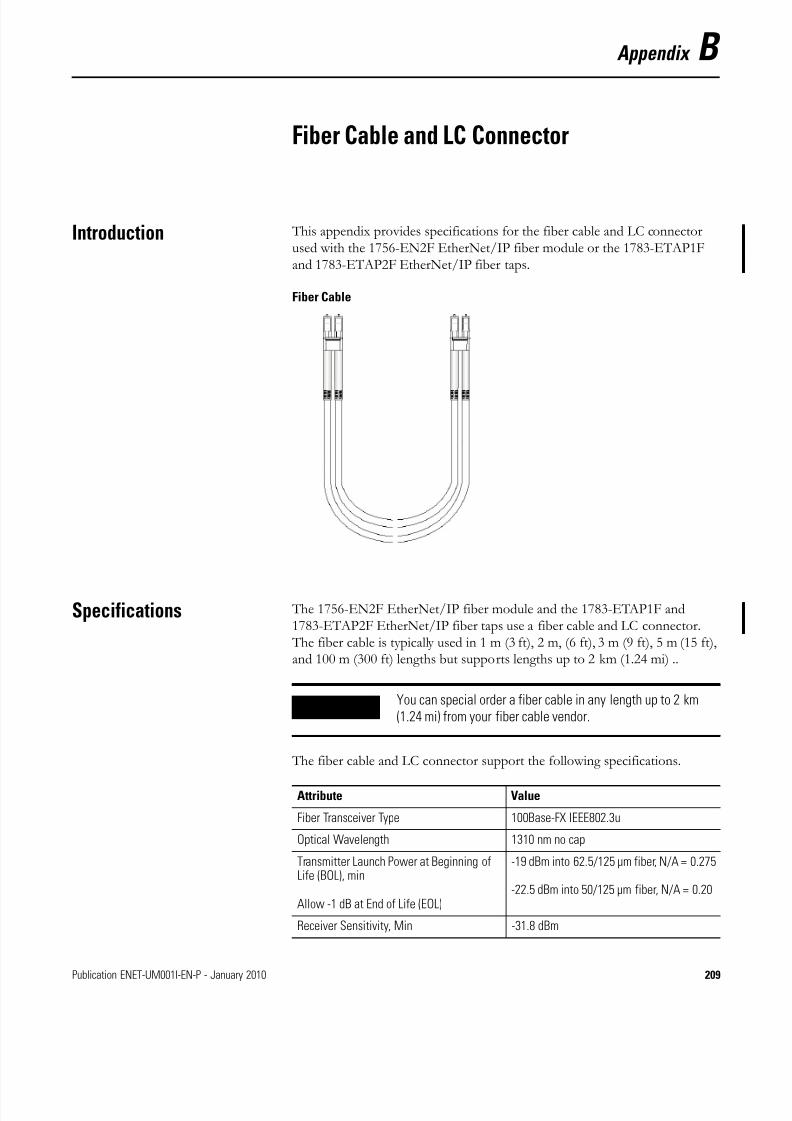
8/13/2019 EtherNet-IP Modules in Logix5000 Control Systems User Manual
http://slidepdf.com/reader/full/ethernet-ip-modules-in-logix5000-control-systems-user-manual 209/230
Publication ENET-UM001I-EN-P - January 2010 209
Appendix B
Fiber Cable and LC Connector
Introduction This appendix provides specifications for the fiber cable and LC connectorused with the 1756-EN2F EtherNet/IP fiber module or the 1783-ETAP1Fand 1783-ETAP2F EtherNet/IP fiber taps.
Fiber Cable
Specifications The 1756-EN2F EtherNet/IP fiber module and the 1783-ETAP1F and1783-ETAP2F EtherNet/IP fiber taps use a fiber cable and LC connector. The fiber cable is typically used in 1 m (3 ft), 2 m, (6 ft), 3 m (9 ft), 5 m (15 ft),and 100 m (300 ft) lengths but supports lengths up to 2 km (1.24 mi) ..
The fiber cable and LC connector support the following specifications.
IMPORTANT You can special order a fiber cable in any length up to 2 km(1.24 mi) from your fiber cable vendor.
Attribute Value
Fiber Transceiver Type 100Base-FX IEEE802.3u
Optical Wavelength 1310 nm no cap
Transmitter Launch Power at Beginning ofLife (BOL), min
Allow -1 dB at End of Life (EOL)
-19 dBm into 62.5/125 µm fiber, N/A = 0.275
-22.5 dBm into 50/125 µm fiber, N/A = 0.20
Receiver Sensitivity, Min -31.8 dBm

8/13/2019 EtherNet-IP Modules in Logix5000 Control Systems User Manual
http://slidepdf.com/reader/full/ethernet-ip-modules-in-logix5000-control-systems-user-manual 210/230
210 Publication ENET-UM001I-EN-P - January 2010
Appendix B Fiber Cable and LC Connector
Receiver Sensitivity, Max -14 dBm
Fiber Channel Power Budget at Rated BER(Two connected modules or taps, either the
1756-EN2F EtherNet/IP fiber module, or1783-ETAP1F or 1783-ETAP2F EtherNet/IPfiber taps)
12.8 dB for 62.5/125 µm multimode fiber
9.3 dB for 50/125 µm multimode fiber
Fiber Type Glass
62.5/125 µm and 50/125 µm multimodefiber
Simplex or duplex
Jacket type and jacket diameter isdependent on connector selection
Graded Index (GI) fiber
Per IEC 60794-1-1, IEC 60793-2-10 categoryA1 fibers
Connector Type IEC 61754-20 LC connector, maximuminsertion loss 0.75 dB per connection
Channel Length, Max 2 km (1.24 mi) (1)
(1) The channel, that is, connectors and cable, must not exceed the allowable power budget.
IMPORTANT You should allow at least 5.08 cm (2 in.) for the fiber cable bendradius. Contact the cable manufacturer for more information onrecommended cable bend radius.
Attribute Value

8/13/2019 EtherNet-IP Modules in Logix5000 Control Systems User Manual
http://slidepdf.com/reader/full/ethernet-ip-modules-in-logix5000-control-systems-user-manual 211/230
Publication ENET-UM001I-EN-P - January 2010 211
Fiber Cable and LC Connector Appendix B
EXAMPLE In the example shown here, the channel insertion loss is calculated for an optical channel based on thefollowing factors:
• 1 dB/km fiber
• 0.75 dB per adapter
Note that in this example, the end connectors are not factored in the calculations.
The maximum power budget for this example is 12.8 dB for 62.5/125 um fiber. Therefore, the channelinsertion loss for the example of 3.5 dB is less than the maximum power budget.
Fiber 1 dB/km Fiber 1 dB/kmFiber 1 dB/km0.75 dB0.75 dB
1km0.75km 0.25km
0.75 dB 0.75 dB 0.75dB 0.25 dB1 dB+ + + +
Total channel insertion loss = 3.5 db

8/13/2019 EtherNet-IP Modules in Logix5000 Control Systems User Manual
http://slidepdf.com/reader/full/ethernet-ip-modules-in-logix5000-control-systems-user-manual 212/230
212 Publication ENET-UM001I-EN-P - January 2010
Appendix B Fiber Cable and LC Connector
Notes:

8/13/2019 EtherNet-IP Modules in Logix5000 Control Systems User Manual
http://slidepdf.com/reader/full/ethernet-ip-modules-in-logix5000-control-systems-user-manual 213/230
Publication ENET-UM001I-EN-P - January 2010 213
Appendix C
EtherNet/IP Network Connections
Introduction EtherNet/IP communication modules use connections to managecommunication. A connection is a point-to-point communication mechanismused to transfer data between a transmitter and a receiver. The EtherNet/IPcommunication modules use these connections:
• CIP connections for Logix-based communication.
A CIP connection transfers data from one Logix application running onone end node to a second Logix application running on another endnode. A CIP connection is established over a TCP connection.
• TCP/IP connections for EtherNet/IP communication.
A single TCP connection can support multiple CIP connections.
CIP Connections Connected modules communicate more reliably than do unconnectedmodules.
Examples of functions supported by CIP implicit (connected) messaginginclude:
• Logix controller message transfer to Logix controller.
• I/O or produced/consumed tag.
• program upload.
• RSLinx DDE/OPC client.
• PanelView polling of Logix controller.
Topic Page
CIP Connections 213
TCP Connections 214
Multicast Address Limit 215
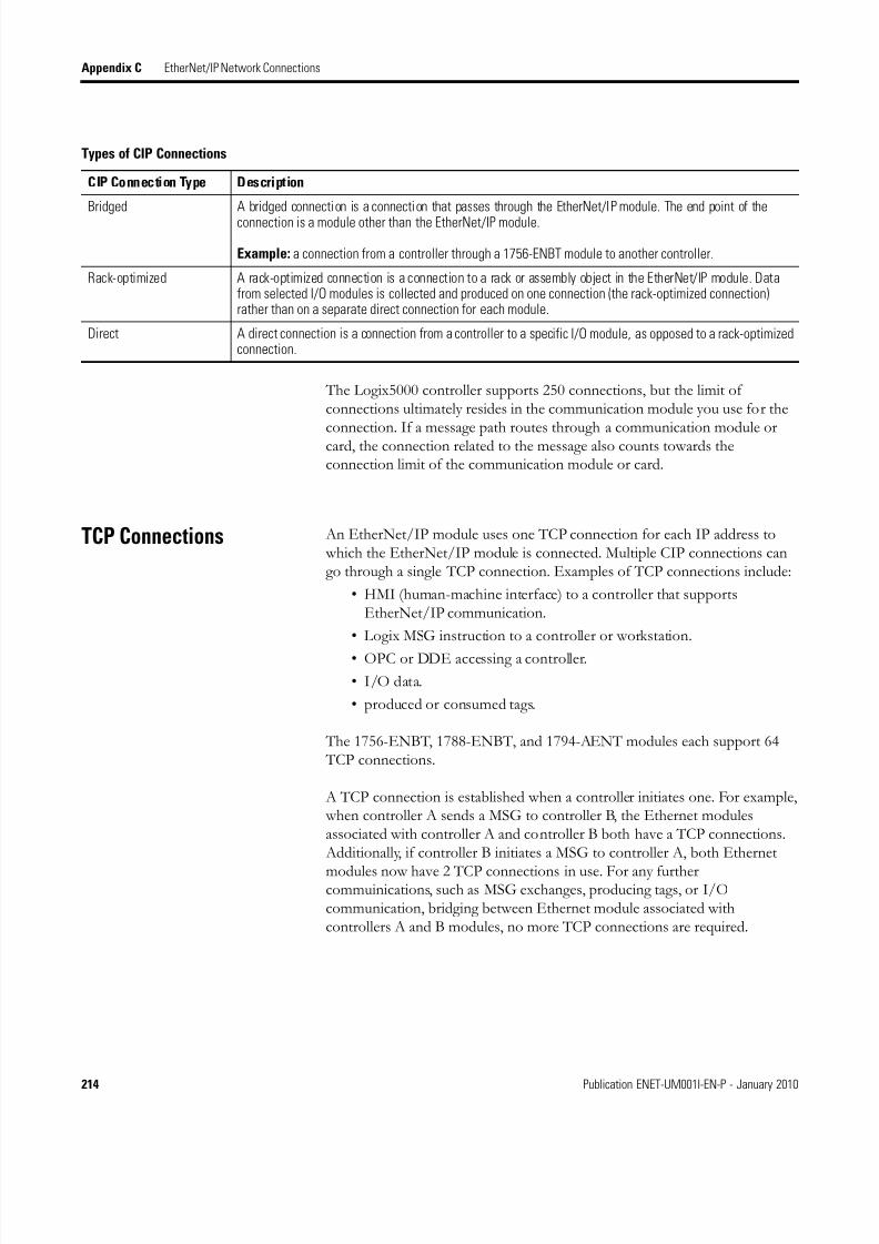
8/13/2019 EtherNet-IP Modules in Logix5000 Control Systems User Manual
http://slidepdf.com/reader/full/ethernet-ip-modules-in-logix5000-control-systems-user-manual 214/230
214 Publication ENET-UM001I-EN-P - January 2010
Appendix C EtherNet/IP Network Connections
The Logix5000 controller supports 250 connections, but the limit ofconnections ultimately resides in the communication module you use for the
connection. If a message path routes through a communication module orcard, the connection related to the message also counts towards theconnection limit of the communication module or card.
TCP Connections An EtherNet/IP module uses one TCP connection for each IP address to which the EtherNet/IP module is connected. Multiple CIP connections cango through a single TCP connection. Examples of TCP connections include:
• HMI (human-machine interface) to a controller that supportsEtherNet/IP communication.
• Logix MSG instruction to a controller or workstation.
• OPC or DDE accessing a controller.
• I/O data.
• produced or consumed tags.
The 1756-ENBT, 1788-ENBT, and 1794-AENT modules each support 64 TCP connections.
A TCP connection is established when a controller initiates one. For example, when controller A sends a MSG to controller B, the Ethernet modulesassociated with controller A and controller B both have a TCP connections. Additionally, if controller B initiates a MSG to controller A, both Ethernet
modules now have 2 TCP connections in use. For any furthercommuinications, such as MSG exchanges, producing tags, or I/Ocommunication, bridging between Ethernet module associated withcontrollers A and B modules, no more TCP connections are required.
Types of CIP Connections
CIP Connection Type Description
Bridged A bridged connection is a connection that passes through the EtherNet/IP module. The end point of the
connection is a module other than the EtherNet/IP module.
Example: a connection from a controller through a 1756-ENBT module to another controller.
Rack-optimized A rack-optimized connection is a connection to a rack or assembly object in the EtherNet/IP module. Datafrom selected I/O modules is collected and produced on one connection (the rack-optimized connection)rather than on a separate direct connection for each module.
Direct A direct connection is a connection from a controller to a specific I/O module, as opposed to a rack-optimizedconnection.

8/13/2019 EtherNet-IP Modules in Logix5000 Control Systems User Manual
http://slidepdf.com/reader/full/ethernet-ip-modules-in-logix5000-control-systems-user-manual 215/230
Publication ENET-UM001I-EN-P - January 2010 215
EtherNet/IP Network Connections Appendix C
Multicast Address Limit Connections that produce data over an Ethernet network use multicastaddresses. EtherNet/IP modules support a maximum of 32 unique multicastaddresses. The actual address, such as 239.192.22.121, is determined by theEtherNet/IP module.
Example 1: An Ethernet adapter that produces data uses a unique multicastaddress for each I/O connection.
Example 2: A Logix controller that produces tags uses a unique multicastaddress for each produced tag.
The multicast address limit is independent of the connection limit for amodule. Not all connections require a multicast address. And for producedand consumed tags, one produced tag requires one multicast address and oneconnection for each consumer. For multiple consumers, the one multicastaddress would use multiple connections.
Requested PacketInterval (RPI)
The RPI is the update rate specified for a particular piece of data on thenetwork. The RPI can be specified for an entire rack (using a rack-optimizedconnection) or for a particular module (using a direct connection).
When adding a module to the I/O configuration of a controller, you mustconfigure the RPI. This value specifies how often to produce the data for thatmodule. For example, if you specify an RPI of 50 ms, every 50 ms the I/Omodule sends its data to the controller or that the controller sends its data tothe I/O module.
RPIs are used only for implicit connections, such as produced/consumed tagsand I/O. For example, a local EtherNet/IP communication module does notrequire an RPI because it does not produce data for the system but acts only asa bridge to remote modules.
Set the RPI only as fast as needed by the application. The RPI also determinesthe number of packets per second that the module will produce on aconnection.
Each module has a limit on the total number of implicit packets per second. The total includes the sum of sent and received implicit packets. The packet
rate for implicit messages is for implicit only, and neither matches nor includesthe explicit packet rate.

8/13/2019 EtherNet-IP Modules in Logix5000 Control Systems User Manual
http://slidepdf.com/reader/full/ethernet-ip-modules-in-logix5000-control-systems-user-manual 216/230
216 Publication ENET-UM001I-EN-P - January 2010
Appendix C EtherNet/IP Network Connections
Notes:

8/13/2019 EtherNet-IP Modules in Logix5000 Control Systems User Manual
http://slidepdf.com/reader/full/ethernet-ip-modules-in-logix5000-control-systems-user-manual 217/230
Publication ENET-UM001I-EN-P - January 2010 217
Appendix D
EtherNet/IP Network Overview
Introduction This appendix defines some basic Ethernet network concepts and how the
EtherNet/IP protocol is used for control.
Ethernet Protocols On the most basic level, Ethernet is a wire or cable that connects computersand peripheral modules so that they can communicate. The actual wire usedfor the network is referred to as the network medium. Beyond the physicalmedium, all Ethernet networks support protocols that provide sophisticateddata transfer and network management capability.
Topic Page
Ethernet Protocols 217
Configuration Requirements 219
Manual Configuration on an Ethernet Switch 222
Change Ports on an Ethernet Switch 222
Additional Resources 222
Protocol Descriptions
Protocol DescriptionTransmission controlprotocol/internet protocol(TCP/IP)
TCP/IP is a transport-layer protocol (TCP) and a network-layer protocol (IP) commonly used in businessenvironments for communication within networks and across internetworks. The EtherNet/IPcommunication modules use TCP/IP for explicit messaging, that is, messages in which time is not acritical factor, such as uploading or downloading programs.
User datagramprotocol/Internet protocol(UDP/IP)
UDP is a much simpler transport protocol. It is connectionless and provides a simple means of sendingdatagrams between two modules. UDP is used by applications that implement their own handshakingbetween modules and only require minimal transport service. UDP is smaller, simpler, and faster thanTCP and can operate in unicast, multicast, or broadcast mode. The EtherNet/IP communication modulesuse UDP/IP for real time I/O messaging.
CIP CIP applies a common application layer over an Ethernet network by encapsulating messages inTCP/UDP/IP. This common application layer is the control and information protocol (CIP), which providesinteroperability and interchangeability of industrial automation and control modules on an Ethernetnetwork. EtherNet/IP supports both real-time I/O (implicit messaging) and explicit messaging.
See the EtherNet/IP Performance and Application Guide, publication ENET-AP001, for more informationon EtherNet/IP.

8/13/2019 EtherNet-IP Modules in Logix5000 Control Systems User Manual
http://slidepdf.com/reader/full/ethernet-ip-modules-in-logix5000-control-systems-user-manual 218/230
218 Publication ENET-UM001I-EN-P - January 2010
Appendix D EtherNet/IP Network Overview
Use of the Common Industrial Protocol (CIP)
The EtherNet/IP communication modules use the Common IndustrialProtocol (CIP). CIP is the application layer protocol specified forEtherNet/IP, the Ethernet Industrial Protocol, as well as for ControlNet andDeviceNet.
CIP is a message-based protocol that implements a relative path to send amessage from the producing module in a system to the consuming modules.
The producing module contains the path information that steers the messagealong the proper route to reach its consumers. Since the producing moduleholds this information, other modules along the path simply pass it alongbecause they do not need to store the information. This information handlinghas two significant benefits.
• You do not need to configure routing tables in the bridging module, which greatly simplifies maintenance and module replacement.
• You maintain full control over the route taken by each message, whichenables you to select alternative paths for the same end module.
CIP uses the producer/consumer networking model instead of asource/destination (master/slave) model. The producer/consumer modelreduces network traffic and increases speed of transmission.
In traditional I/O systems, controllers poll input modules to obtain their inputstatus. In the CIP system, digital input modules are not polled by a controller.Instead, they produce (multicast) their data either upon a change of state
Simple network managementprotocol (SNMP)
SNMP is a standard for network management within TCP/IP environments. This protocol enables clientapplications monitor and manage network information on host computers and gateways. This protocol
is password-protected.
SNMP uses a distributed architecture consisting of management systems and agents. Data is passedfrom SNMP agents, which are hardware or software processes reporting activity in each networkmodule (switch, router or bridge) to the workstation console used to oversee the network. The agentsreturn information contained in a management information base (MIB), which is a data structure thatdefines what is obtainable from the module and what can be controlled.
Internet Group Managementprotocol (IGMP) snooping
IGMP snooping enables switches to route multicast traffic by distributing each packet only to the portsthat need to receive it. Many switches support this feature. However, for IGMP snooping to work, mostof these switches require a system router. If your control system is a stand-alone network or is requiredto continue performing if the router is out of service, make sure the switch you are using supports IGMPsnooping without a router present.
This feature is highly recommended for EtherNet/IP systems the control I/O.
Protocol Descriptions
Protocol Description

8/13/2019 EtherNet-IP Modules in Logix5000 Control Systems User Manual
http://slidepdf.com/reader/full/ethernet-ip-modules-in-logix5000-control-systems-user-manual 219/230
Publication ENET-UM001I-EN-P - January 2010 219
EtherNet/IP Network Overview Appendix D
(COS) or at a requested packet interval (RPI). The frequency of updatedepends upon the options chosen during configuration and where on thenetwork the input module resides. The input module, therefore, is a producerof input data and the controller is a consumer of the data.
The controller can also produce data for other controllers to consume. Theproduced and consumed data is accessible by multiple controllers over theLogix backplane and over the EtherNet/IP network. This data exchangeconforms to the producer/consumer model.
ConfigurationRequirements
Before you can use an EtherNet/IP module, you must configure its IPaddress, gateway address, and subnet mask.
IP Address
The IP address identifies each node on the IP network or system of connectednetworks. Each TCP/IP node on a network must have a unique IP address.
The IP address is 32 bits long and has a network ID part and a host ID part.
Because networks vary in size, there are four types of networks.
The network class determines how an IP address is formatted.
IMPORTANT Contact your network administrator or the Network InformationCenter for a unique fixed IP address to assign to the EtherNet/IPmodule.
EtherNet/IP Network Types
Network Type For
Class A Large networks with many devices
Class B Medium-sized networks
Class C Small networks (fewer than 256 devices)
Class D Multicast addresses
Class A
Class B
Class C
network (7 bits)
network (14 bits)
network (21 bits) local address (8 bits)
local address (16 bits)
local address (24 bits)0
0
0
0
0
0
1
1 1
8
8
8
16
16
16 24
24
24
31
31
31
Class D multicast address (28 bits)
0
0 11 1
318 16 24

8/13/2019 EtherNet-IP Modules in Logix5000 Control Systems User Manual
http://slidepdf.com/reader/full/ethernet-ip-modules-in-logix5000-control-systems-user-manual 220/230
220 Publication ENET-UM001I-EN-P - January 2010
Appendix D EtherNet/IP Network Overview
Each node on the same physical network must have an IP address of the sameclass and must have the same network ID. Each node on the same networkmust have a different local address (host ID), thus giving it a unique IPaddress.
IP addresses are written as four-decimal integers (0...255) separated by periods where each integer gives the value of one byte of the IP address.
For example, the 32-bit IP address:
10000010 00000000 00000000 00000001 is written as 130.0.0.1.
Gateways
A gateway connects individual physical networks into a system of networks. When a node needs to communicate with a node on another network, agateway transfers the data between the two networks. The following figure
shows gateway G connecting Network 1 with Network 2.
When host B with IP address 128.2.0.1 communicates with host C, it knowsfrom C’s IP address that C is on the same network. In an Ethernetenvironment, B can then resolve C’s IP address to a MAC address andcommunicate with C directly.
IP Address Class
Class Leftmost Bits Start Address Finish Address
A 0xxx 0.0.0. 127.255.255.255
B 10xx 128.0.0.0 191.255.255.255C 110x 192.0.0.0 223.255.255.255
D 1110 224.0.0.0 239.255.255.255
128.1.0.1
128.2.0.1 128.2.0.2
128.2.0.3
128.1.0.2
A
B C
G
Network 1
Network 2

8/13/2019 EtherNet-IP Modules in Logix5000 Control Systems User Manual
http://slidepdf.com/reader/full/ethernet-ip-modules-in-logix5000-control-systems-user-manual 221/230
Publication ENET-UM001I-EN-P - January 2010 221
EtherNet/IP Network Overview Appendix D
When host B communicates with host A, it knows from A’s IP address that Ais on another network because the network IDs differ. To send data to A, Bmust have the IP address of the gateway connecting the two networks. In thisexample, the gateway’s IP address on Network 2 is 128.2.0.3.
The gateway has two IP addresses (128.1.0.2 and 128.2.0.3). Network 1 hostsmust use the first IP address, and Network 2 hosts must use the second IPaddress. To be usable, a host’s gateway IP address must match its own net ID.
Subnet Mask
Subnet addressing is an extension of the IP address scheme that enables a siteto use a single net ID for multiple physical networks. Routing outside of thesite continues by dividing the IP address into a net ID and a host ID via the IP
class. Inside a site, the subnet mask is used to redivide the IP address into acustom net ID portion and host ID portion.
Take Network 2 (a Class B network) in the previous example and add anotherphysical network. Selecting this subnet mask would add two additional net IDbits allowing for four physical networks.
11111111 11111111 11000000 00000000 = 255.255.192.0
Two bits of the Class B host ID have been used to extend the net ID. Eachunique combination of bits in the part of the host ID where subnet mask bitsare 1 specifies a different physical network.
New Configuration
128.1.0.1
128.2.64.1 128.2.64.2
128.2.64.3
128.1.0.2
A
B C
G
Network 1
Network 2.1
128.2.128.1 128.2.128.2
128.2.128.3D E
G2
Network 2.2

8/13/2019 EtherNet-IP Modules in Logix5000 Control Systems User Manual
http://slidepdf.com/reader/full/ethernet-ip-modules-in-logix5000-control-systems-user-manual 222/230

8/13/2019 EtherNet-IP Modules in Logix5000 Control Systems User Manual
http://slidepdf.com/reader/full/ethernet-ip-modules-in-logix5000-control-systems-user-manual 223/230

8/13/2019 EtherNet-IP Modules in Logix5000 Control Systems User Manual
http://slidepdf.com/reader/full/ethernet-ip-modules-in-logix5000-control-systems-user-manual 224/230
224 Publication ENET-UM001I-EN-P - January 2010
Index
Cchange ports 222CIP connections 30, 213communication driver 34-35
communication format 82-87choosing direct or rack-optimizedconnection 83direct connections 84ownership 86-87rack-optimized connections 85
configuration parametersbeacon interval 70beacon timeout 70ring protocol VLAN ID 70
configureDHCP software 51EtherNet/IP modules 41-55
MSG instructions 127personal computer 33-35RSLinx communication software 48-49RSLogix 5000 programming software 50Stratix switches 37-39
connectionscaching MSG instructions 106CIP 30, 213data transfer 106I/O 83interlocking 96messaging 106
multicast address limits 215overview 213-215produced and consumed tags 96TCP 30, 214to PanelView terminals 132to RSView applications 136troubleshooting 152
consume tags 95, 100-104control application 55control I/O
adding distributed I/O modules 78-81communication format 82-87connections 83
hardware 77-92ownership 86RPI 88
control system 23controller ownership 86convert between INTs and DINTs 115
Ddata transfer
caching connections 106configuring 111-114
connections 106guidelines 105logic 107-110mapping tags 116overview 93-118to PLC-5 or SLC processors 115
device-level ring network 57-75supervisor node 61-62
DHCP software 51diagnostics
Ethernet statistics 144message connections 142monitor 137-145
network settings 141overview 138
direct connection 83DNS addressing 54-55domain name 42download 55driver 34-35duplicate address detection 51-53
Eemail
MSG instruction 127overview 119send through an EtherNet/IP module 119-130sending via MSG instruction 121-128status codes 129text format 129
Ethernet protocols 217-219EtherNet/IP modules
bridging 27-29configuring 41-55connections 213-215control application 55
features 13-31network overview 217-222network specifications 30set IP network address 43setting IP network address 43status indicators 167-208using in control system 23

8/13/2019 EtherNet-IP Modules in Logix5000 Control Systems User Manual
http://slidepdf.com/reader/full/ethernet-ip-modules-in-logix5000-control-systems-user-manual 225/230
Publication ENET-UM001I-EN-P - January 2010 225
Index
examplesaccessing distributed I/O modules 91bridging 29buffering INTs 117RSLinx communication software bridging
28
Ffiber cable
specifications 209flash upgrade firmware
USB port 165
Ggateway 42, 220Guard I/O modules 25
in EtherNet/IP system 24
Hhost name 42
II/O
controlling over EtherNet/IP 77-92interlocking
connections 96
consume tags 100-104organize tags 95overview 93-118produce tags 98-99terminology 95
IP addressesdefinition 41DHCP software 51duplication address detection 51-53network address configuration switchsettings 44overview 219RSLinx communication software 48-49
RSLogix 5000 programming software 50set 43swapping in redundant systems 53
Mmanual configuration 222map tags 116
messagingcaching connections 106configuring 111-114connections 106guidelines 105
logic 107-110mapping tags 116overview 93-118to PLC-5 or SLC processor 115
MSG instructioncaching connections 106configuring 111-114connections 106logic 107-110mapping tags 116sending email 127sending via an email 121-128to PLC-5 or SLC processors
115
MSG instructionsguidelines 105
Nnetwork address
DNS addressing 54-55set IP network address 43
network overviewmodules in an EtherNet/IP control system 23
network parameters 47
DNS addressing 42domain name 42gateway 42host name 42IP addresses 41subnet mask 41
Oownership 86
listen-only connection 86owner controller 86
PPanelView terminals
adding in RSLogix 5000 programmingsoftware 133-135communication with Logix controller overEtherNet/IP 131-136determining connections 132organizing controller data 136set up hardware 131

8/13/2019 EtherNet-IP Modules in Logix5000 Control Systems User Manual
http://slidepdf.com/reader/full/ethernet-ip-modules-in-logix5000-control-systems-user-manual 226/230
226 Publication ENET-UM001I-EN-P - January 2010
Index
personal computersplacing on network 33-35
PLC-5 processor 115produce tags 95, 98-99produced and consumed tags
connections 96consume tags 100-104number of multicast 31organize tags 95overview 93-118produce tags 98-99set up hardware 93terminology 95
Rrack-optimized connection 83
remote adapter 87requested packet interval 88-89, 215ring protocol VLAN ID 70ring supervisor
configure with RSLogix 5000programming software 64enable in RSLogix 5000 programmingsoftware 68
RPI 88RSLinx communication software
bridging 28communication driver 34-35configuring network parameters 48-49
RSLogix 5000 programming softwareadding a PanelView terminal 133-135adding distributed I/O modules 78-81, 91configure a ring supervisor 64consume a tag 100-104enable ring supervisor 68produce a tag 98-99set the requested packet interval 88-89setting IP network address 43verify supervisor configuration 75
Ssafety
additional resources 26architectures 26Guard I/O modules in EtherNet/IP system 24
select a remote adapter 87serial communication
USB port 161-165
set IP network address 43BOOTP/DHCP server 45-46RSLinx communication software orRSLogix 5000 programming software 43thumbwheel switch 43
set the requested packet intervalwith RSLogix 5000 programmingsoftware 88-89
set up hardwaredata transfer 93I/O modules over EtherNet/IP 77interlocking 93messaging 93PanelView terminals and Logixcontrollers 131produced and consumed tags 93Stratix switches 38
to share data via a USB port 161set up I/Ocontrolling I/O 77-92
set up USB driver 163SLC processor 115specifications
EtherNet/IP network 30fiber cable 209
status codesemail 129
status indicators1734-AENT and 1734-AENTR modules 1921738-AENT and 1738-AENTR modules 1951756-EN2F module 1711756-EN2T module 1731756-EN2TR module 1751756-EN2TXT module 1771756-ENBT module 1691768-ENBT module 1851769-L23E-QB1B and 1769-L23E-QBFC1Bmodules 1781769-L32E and 1769-L35E modules
status indicators 183
1783-ETAP, 1783-ETAP1F, and1783-ETAP2F taps 1871788-ENBT module 1891794-AENT module 1992x-COMM-E modules 201, 205EtherNet/IP Modules 167-208
Stratix switches 37-39additional resources 39features 38-39select a switch 37set up hardware 38

8/13/2019 EtherNet-IP Modules in Logix5000 Control Systems User Manual
http://slidepdf.com/reader/full/ethernet-ip-modules-in-logix5000-control-systems-user-manual 227/230
Publication ENET-UM001I-EN-P - January 2010 227
Index
string tags 121subnet mask 41, 221supervisor configuration
verify 75supervisor node 61-62swap IP addresses 53switch considerations 157-159switches 222
IP network address configuration settings 44select a Stratix switch 37Stratix switch features 38-39Stratix switches 37-39
T tags
produced and consumed 31TCP connections 214
thumbwheel switchset IP network address 43
troubleshootDLR network 75Ethernet statistics 153-156EtherNet/IP modules 147-159I/O connections 153
message connections 152switch considerations 157-159web browser support 147-156with a virtual local area network 158
UUSB port
configure a module 162-165flash upgrade firmware 165serial communication 161-165set up hardware 161
Wweb browser support 147-156

8/13/2019 EtherNet-IP Modules in Logix5000 Control Systems User Manual
http://slidepdf.com/reader/full/ethernet-ip-modules-in-logix5000-control-systems-user-manual 228/230
228 Publication ENET-UM001I-EN-P - January 2010
Index

8/13/2019 EtherNet-IP Modules in Logix5000 Control Systems User Manual
http://slidepdf.com/reader/full/ethernet-ip-modules-in-logix5000-control-systems-user-manual 229/230
8/13/2019 EtherNet-IP Modules in Logix5000 Control Systems User Manual
http://slidepdf.com/reader/full/ethernet-ip-modules-in-logix5000-control-systems-user-manual 230/230
Rockwell Automation Support
Rockwell Automation provides technical information on the Web to assist you in using its products. Athttp://www.rockwellautomation.com/support/, you can find technical manuals, a knowledge base of FAQs, technical andapplication notes, sample code and links to software service packs, and a MySupport feature that you can customize to make the
best use of these tools.
For an additional level of technical phone support for installation, configuration, and troubleshooting, we offer TechConnectsupport programs. For more information, contact your local distributor or Rockwell Automation representative, or visit
http://www.rockwellautomation.com/support/.