Embed Size (px)
Citation preview

© 2009 Cisco Systems, Inc. All rights reserved. Cisco Public Presentation_ID 1
Ethernet OAM Technologies
Santanu Dasgupta [email protected]

© 2009 Cisco Systems, Inc. All rights reserved. Cisco Public 2
Operations, Administration & Maintenance
FCAPS F – Fault Management
C – Configuration Management
A – Accounting
P – Performance Management
S – Security Management

© 2009 Cisco Systems, Inc. All rights reserved. Cisco Public 3
Problem Scope A few possible scenarios
U-PE A
U-PE B U-PE C
N-PE 3
N-PE 4 N-PE 2
N-PE 1
Customer Equipment
CE
CE CE
Ethernet UNI
SP Network
PW
Access Core
CE
U-PE D
Ethernet UNI
MPLS
MPLS SONET/SDH
Native Ethernet
Physical link failure
UNI port failure
U-PE device failure
Physical link failure
VFI failure
Physical link failure P-Router
failure
PW failure VLAN to VFI
xconnect failure
Duplex mismatch
Speed mismatch
D-LDP session failure
VC failure
AC failure
Uni-directional Link
Excessive Encoding Errors
Excessive FCS Errors
Cross-connected Service
Unexpected Endpoint
LSP Failure
C-VLAN to EVC
mismatch

© 2009 Cisco Systems, Inc. All rights reserved. Cisco Public 4
OAM: The Concept Operations, Administration, Maintenance & Provisioning:
− fault indication − performance monitoring
− security management − diagnostic functions − configuration & service provisioning
OAM covers both N S and WE interfaces
Network Plane (Elements)
Management Plane (NMS / EMS)
N
S
W E

© 2009 Cisco Systems, Inc. All rights reserved. Cisco Public 5
Scope of Ethernet OAM Operations, Administration, Maintenance & Provisioning:
− fault indication − performance monitoring − security management − diagnostic functions − configuration & service provisioning
OAM covers both N S and WE interfaces
Network Plane (NEs)
Management Plane (NMS / EMS)
N
S
W E
Primary Focus of Ethernet OAM protocols is on W E interactions (across NEs)

© 2009 Cisco Systems, Inc. All rights reserved. Cisco Public 6
Drivers for Ethernet OAM
OAM benchmarks Set by TDM and existing WAN technologies
Operational Efficiency Reduce OPEX, avoid truck-rolls
Downtime cost
Management Complexity Large Span Networks
Multiple constituent networks belong to disparate organizations/companies

© 2009 Cisco Systems, Inc. All rights reserved. Cisco Public 7
Agenda
Protocol Overview CFM or IEEE 802.1ag
ITU Y.1731
Link OAM or IEEE 802.3ah (clause 57)
MEF E-LMI
OAM Inter-Working
Fault Management scenarios
Performance Management

© 2009 Cisco Systems, Inc. All rights reserved. Cisco Public Presentation_ID 8
Ethernet OAM Protocol Overview

© 2009 Cisco Systems, Inc. All rights reserved. Cisco Public 9
Problem Taxonomy Fault Management
Fault Detection Fault Notification Fault Verification Fault Isolation Fault Recovery
Configuration Management Service Provisioning
Performance Management Frame Loss Measurement Delay Measurement Delay Variation Measurement Availability Measurement
Carrier Ethernet Services

© 2009 Cisco Systems, Inc. All rights reserved. Cisco Public 10
Ethernet OAM Building Blocks
Fault Management
Performance Management
Configuration Management
Fault Management
Fault Management
Performance Management
Configuration Management
Performance Management
Fault Management
Performance Management
Configuration Management
Configuration Management
802.3ah
E-LMI Cisco
IP SLAs
802.1ag / Y.1731 E-LMI
IEEE 802.1ag: Connectivity Fault Management (CFM) IEEE 802.3ah: Ethernet Link OAM (EFM OAM) ITU-T Y.1731: OAM functions and mechanisms for Ethernet based networks MEF E-LMI: Ethernet Local Management Interface Cisco IP SLA’s: Performance Management using CFM and Y.1731 mechanisms

© 2009 Cisco Systems, Inc. All rights reserved. Cisco Public 11
Cisco Carrier Ethernet OAM Protocol Positioning
E-LMI—User to Network Interface (UNI)
Link OAM—Any point-point 802.3 link
CFM—End-to-End UNI to UNI
MPLS OAM—within MPLS cloud
Core Customer
Provider Bridges
Provider Bridges
IP/MPLS
Business
Residential
Business
Residential
UNI UNI NNI NNI NNI
Backbone Bridges
Backbone Bridges
Customer
Ethernet Link OAM
Access Connectivity
Fault Management Access E-LMI
MPLS OAM

© 2009 Cisco Systems, Inc. All rights reserved. Cisco Public Presentation_ID 12
Connectivity Fault Management
IEEE 802.1ag

© 2009 Cisco Systems, Inc. All rights reserved. Cisco Public 13
CFM Overview
Family of protocols that provides capabilities to detect, verify, isolate and report end-to-end ethernet connectivity faults
Employs regular Ethernet frames that travel in-band with the customer traffic
Devices that cannot interpret CFM Messages forward them as normal data frames
CFM frames are distinguishable by Ether-Type (0x8902) and dMAC address (for multicast messages)
Standardized by IEEE in late 2007 IEEE std. 802.1ag-2007

© 2009 Cisco Systems, Inc. All rights reserved. Cisco Public 14
CFM Overview (Cont.)
Key CFM mechanisms include: Nested Maintenance Domains (MDs) that break up the responsibilities for network administration of a given end-to-end service
Maintenance Associations (MAs) that monitor service instances under a given MD
Maintenance Points (MPs) that generate and respond to CFM PDUs
Protocols (Continuity Check, Loopback and Linktrace) used for Fault Management activities
© 2009 Cisco Systems, Inc. All rights reserved. Cisco Public 15
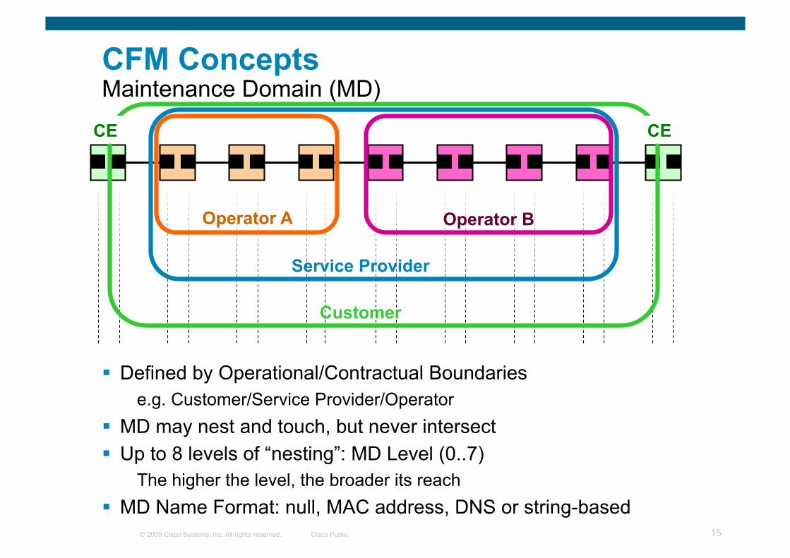
CFM Concepts Maintenance Domain (MD)
Defined by Operational/Contractual Boundaries e.g. Customer/Service Provider/Operator
MD may nest and touch, but never intersect Up to 8 levels of “nesting”: MD Level (0..7)
The higher the level, the broader its reach MD Name Format: null, MAC address, DNS or string-based
Operator A Operator B
Service Provider
Customer
CE CE

© 2009 Cisco Systems, Inc. All rights reserved. Cisco Public 16
Maintenance Domain Nesting

© 2009 Cisco Systems, Inc. All rights reserved. Cisco Public 17
CFM Concepts Maintenance Association (MA)
Monitors connectivity of a particular service instance in a given MD (e.g. 1 service traversing 4 MDs = 4 MAs)
Defined by a set of Maintenance End Points (MEP) at the edge of a domain
Identified by MAID == “Short MA” Name + MD Name Short MA Name Format: Vlan-ID, VPN-ID, integer or string-based
CE CE Operator A Operator B

© 2009 Cisco Systems, Inc. All rights reserved. Cisco Public 18
CFM Concepts Maintenance Point (MP)—MEP
Maintenance Association End Point (MEP) Define the boundaries of a MD Support the detection of connectivity failures between any pair of
MEPs in an MA Associated per MA and identified by a MEPID (1-8191) Can initiate and respond to CFM PDU’s (Active Components)
CE CE Operator A Operator B
MEP MEP
MEP MEP
MEP MEP MEP MEP

© 2009 Cisco Systems, Inc. All rights reserved. Cisco Public 19
CE CE Operator A Operator B
MEP MEP MIP MIP
MEP MEP MIP MIP
MEP MEP MEP MEP
MIP MIP
MIP MIP
MIP MIP
MIP MIP MIP MIP
CFM Concepts Maintenance Point (MP)—MIP
Maintenance Domain Intermediate Point (MIP) Support the discovery of paths among MEPs and location of faults
along those paths Can be associated per MD and VLAN / EVC Can add, check and respond to received CFM PDU’s (Passive)

© 2009 Cisco Systems, Inc. All rights reserved. Cisco Public 20
CFM Concepts UP / Inward-facing MEP
CFM PDUs generated by the MEP are sent towards the Bridge’s Relay Function and not via the wire connected to the port where the MEP is configured
CFM PDUs to be responded by the MEP are expected to arrive via the Bridge’s Relay Function
Applicable to switches Port A
Bridge
Relay Entity
Port B
CFM PDUs

© 2009 Cisco Systems, Inc. All rights reserved. Cisco Public 21
CFM Concepts DOWN / Outward-facing MEP
CFM PDUs generated by the MEP are sent via the wire connected to the port where the MEP is configured
CFM PDUs to be responded by the MEP are expected to arrive via the wire connected to the port where the MEP is configured
Port MEP – special Down MEP at level zero (0) used to detect faults at the link level (rather than service)
Applicable to routers and switches
Port A
Bridge / Router
Relay Entity
Port B
CFM PDUs

© 2009 Cisco Systems, Inc. All rights reserved. Cisco Public 22
Monitored area
CFM Concepts MAs and UP/DOWN MEPs
Applicability of UP/DOWN MEPs in switches:
DOWN MEPs are typically used for MAs spanning a single link UP MEPs are commonly used for MAs with a wider reach (e.g. end-to-end, beyond a single link
Bridge
Port
Bridge 1
Relay Entity
Bridge
Port
Bridge
Port
Bridge 2
Relay Entity
Bridge
Port
Monitored area
Bridge
Port
Bridge 1
Relay Entity
Bridge
Port
Bridge
Port
Bridge 2
Relay Entity
Bridge
Port
UP MEP to UP MEP
DOWN MEP to UP MEP
Monitored area
Bridge
Port
Bridge 1
Relay Entity
Bridge
Port
Bridge
Port
Bridge 2
Relay Entity
Bridge
Port
DOWN MEP to DOWN MEP

© 2009 Cisco Systems, Inc. All rights reserved. Cisco Public 23
CFM Protocols
There are three (3) protocols defined by CFM
Continuity Check Protocol Fault Detection
Fault Notification
Loopback Protocol Fault Verification
Linktrace Protocol Path discovery & Fault Isolation

© 2009 Cisco Systems, Inc. All rights reserved. Cisco Public 24
CFM Protocols Continuity Check Protocol
CE CE Operator A Operator B
MEP MEP MIP MIP Catalogue Catalogue
Catalogue and Terminate
1 2 3 1. Continuity Check Message (CCM) X
Used for Fault Detection and Notification Per-Maintenance Association multicast “heart-beat” messages
Transmitted at configurable periodic interval by MEPs (3.3ms, 10ms, 100ms, 1s, 10s, 1m, 10m) Uni-directional (no response required) Carries status of port on which MEP is configured
Catalogued by MIPs at the same MD-Level, Terminated by remote MEPs in the same MA

© 2009 Cisco Systems, Inc. All rights reserved. Cisco Public 25
CFM Protocols Continuity Check Protocol—Fault Detection
CCM-based Events IOS Alarm Name
IEEE Alarm Name
Discovery of a remote MEP for the first time CCM MEP UP (New) none
Re-discovery of a previously expired remote MEP CCM MEP UP (Returning) none
Reception by a MEP of a CCM containing a UP Port Status TLV or Interface Status TLV (Remote port recovery)
CCM MEP UP (portstate change) none
Reception by a MEP of CCM’s from ALL remote MEPs configured in a static list
Crosscheck Service Up none
Expiration of CCM entry with an incorrect mpid CCM MEP Down (configClear) none
Expiration of looped CCM entry CCM MEP Down (loopClear) none
Expiration of CCM entry with an incorrect MAID CCM MEP Down (xconnectClear) none
Expiration of CCM entry from a MEP not included in a static list
CCM MEP Down (unknownClear) none
MEF working on to address this

© 2009 Cisco Systems, Inc. All rights reserved. Cisco Public 26
CFM Protocols Loopback Protocol
CE CE Operator A Operator B
MEP MEP MIP MIP S D
1. Loopback Message (LBM) 2. Loopback Reply (LBR)
1 2
1 2
Used for Fault Verification—Ethernet Ping
MEP can transmit a unicast LBM to a MEP or MIP in the same MA
Receiving MP responds by transforming the LBM into a unicast LBR sent back to the originating MEP

© 2009 Cisco Systems, Inc. All rights reserved. Cisco Public 27
CFM Protocols Linktrace Protocol
Used for Path Discovery and Fault Isolation—Ethernet Traceroute
MEP can transmit a multicast message (LTM) in order to discover the MPs and path to a MIP or MEP in the same MA
Each MIP along the path and the terminating MP return a unicast LTR to originating MEP
CE CE Operator A Operator B
MEP MEP MIP MIP S D
1 3 5
2 4 6
1. 1, 3, 5 Linktrace Message (LTM) 2. 2, 4, 6 Linktrace Reply (LTR)
X Y
© 2009 Cisco Systems, Inc. All rights reserved. Cisco Public 28
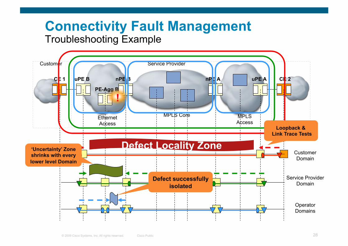
Connectivity Fault Management Troubleshooting Example
CE 1
MPLS Access
MPLS Core Ethernet Access
CE 2 uPE A nPE A nPE B uPE B Customer Service Provider
PE-Agg B
Service Provider Domain
Operator Domains
Customer Domain
!
Defect Locality Zone
Loopback & Link Trace Tests
‘Uncertainty’ Zone shrinks with every lower level Domain
Defect successfully isolated

© 2009 Cisco Systems, Inc. All rights reserved. Cisco Public 29
CFM Protocols Putting Everything Together
1. Run Connectivity Check to proactively detect a soft or hard failure
2. Upon a failure detection, use Loopback to verify it
3. Upon verification, run Traceroute to isolate it; multiple segment LPs can also be used to isolate the fault
4. If the isolated fault points to a virtual circuit, then the OAM tools for that technology can be used to further fault isolation—e.g., for MPLS PW, VCCV and MPLS ping can be used

© 2009 Cisco Systems, Inc. All rights reserved. Cisco Public Presentation_ID 30
ITU-T Y.1731

© 2009 Cisco Systems, Inc. All rights reserved. Cisco Public 31
ITU-T Y.1731 Overview
ITU-T recommendation that provides mechanisms for user-plane OAM functionality in Ethernet networks Covers:
Fault Management mechanisms
Performance Management mechanisms
Standardized by ITU-T SG 13 in May 2006 Latest published version dated Feb. 2008 after IEEE 802.1ag standardization
Frames format (Multicast Address, Ethertype, and common OAM PDU fields) and base functionality are mostly agreed across IEEE 802.1ag and Y.1731

© 2009 Cisco Systems, Inc. All rights reserved. Cisco Public 32
ITU-T Y.1731 Overview OAM Functions for Fault Management
Feature ITU-T Y.1731
IEEE CFM Comments
Ethernet Continuity Check ETH-CC CC
Proactive fault detection, fault notification
Not compatible. Different formats for short MA / MEG ID
IEEE defines mcast DA CCM, ITU defines mcast/ucast DA CCM
Ethernet Loopback ETH-LB LB
On-demand service / fault verification
Compatible operations between IEEE and ITU
IEEE defines ucast DA LBM, ITU defines mcast/ucast DA LBM
Ethernet Link Trace ETH-LT LT On-demand path discovery / fault isolation
Compatible operations between IEEE and ITU
Ethernet Remote Defect Indication ETH-RDI RDI
Fault propagation in the backward direction (opposite direction of the fault).
IEEE RDI flag and Y.1731 ETH-RDI are in the same position in CCM header. However, CCM formats are not compatible
Ethernet Alarm Indication Signal ETH-AIS --
Fault propagation in the forward direction (same direction of the fault)
Also used to suppress Loss of Continuity alarms following detection of defect conditions

© 2009 Cisco Systems, Inc. All rights reserved. Cisco Public 33
ITU-T Y.1731 Overview OAM Functions for Fault Management
Feature ITU-T Y.1731
IEEE CFM Comments
Ethernet Locked Signal ETH-LCK --
Communicates administrative locking of a MEP
Allows intrusive OAM loopback tests (e.g. during turn up)
Ethernet Test Signal ETH-Test -- One-way on-demand diagnostics
Ethernet Automatic Protection Switching ETH-APS -- Applications defined in ITU-T G.8031 and G.8032 (Ethernet
Linear and Ring Protection Switching)
Ethernet Maintenance Communication Channel
ETH-MCC -- No application / use defined in Y.1731
Ethernet Experimental OAM ETH-EXP -- No application / use defined in Y.1731
Ethernet Vendor-specific OAM ETH-VSP -- No application / use defined in Y.1731
© 2009 Cisco Systems, Inc. All rights reserved. Cisco Public Presentation_ID 34
Link OAM
IEEE 802.3ah (Clause 57)

© 2009 Cisco Systems, Inc. All rights reserved. Cisco Public 35
Link OAM (IEEE 802.3ah, Clause 57)
Provides mechanisms useful for “monitoring link operation”, such as:
Link Monitoring
Remote Failure Indication
Remote Loopback Control
Defines an optional OAM sublayer
Intended for single point-to-point IEEE 802.3 links
Uses “Slow Protocol”(1) frames called OAMPDUs which are never forwarded by MAC clients
Standardized: IEEE 802.3ah, clause 57 (now in IEEE 802.3-2005)
Higher Layers
LLC
OAM (Optional)
MAC
Physical Layer
LAN CSMA/CD
Layers
(1) No more than 10 frames transmitted in any one-second period
OSI Model
Application
Presentation
Session
Transport
Network
Data Link
Physical

© 2009 Cisco Systems, Inc. All rights reserved. Cisco Public 36
IEEE 802.3ah Key Functions
OAM discovery Discover OAM support and capabilities per device
Link monitoring basic error definitions for Ethernet so entities can detect failed and degraded connections
Fault signaling mechanisms for one entity to signal another that it has detected an error
Remote MIB Variable Retrieval Ability to read one/more remote MIB variables from remote DTE
Remote loopback used to troubleshoot networks, allows one station to put the other station into a state whereby all inbound traffic is immediately reflected back onto the link
© 2009 Cisco Systems, Inc. All rights reserved. Cisco Public 37
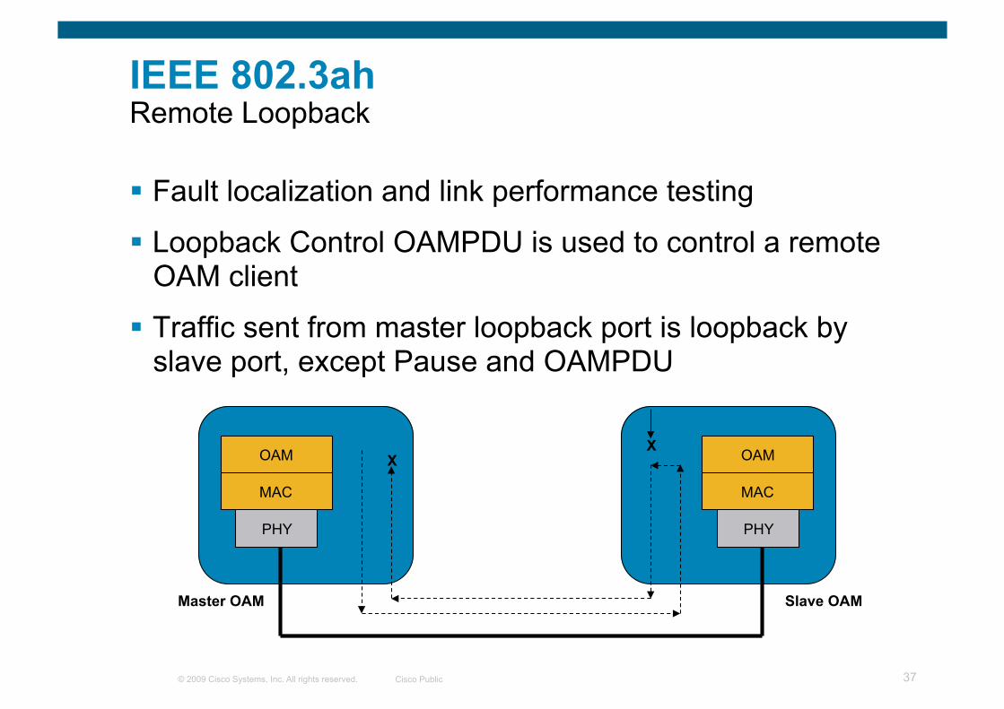
IEEE 802.3ah Remote Loopback
Fault localization and link performance testing
Loopback Control OAMPDU is used to control a remote OAM client
Traffic sent from master loopback port is loopback by slave port, except Pause and OAMPDU
OAM
MAC
PHY
OAM
MAC
PHY
X X
Master OAM Slave OAM

© 2009 Cisco Systems, Inc. All rights reserved. Cisco Public 38
Ethernet Data-Plane Loopback (Proprietary today)
Ethernet data traffic can be looped back on a per port / per VLAN basis
Use cases: Service turn-up Post service turn-up troubleshooting Out-of-service throughput testing
Enabled via CLI configuration Configurable SRC and DST MAC
Addresses swap Configurable direction:
Facility Loopback (facing cloud) Terminal Loopback (facing bridge)
Central Test Head allows for flexible and sophisticated test traffic patterns
Complements CFM Loopback Available in Cisco ME-3400E
UNI Customer CPE
Central Test Head
ME 3400E
Carrier Ethernet Network
NNI Facility Loopback
Terminal Loopback

© 2009 Cisco Systems, Inc. All rights reserved. Cisco Public Presentation_ID 39
Ethernet Local Management Interface
MEF-16

© 2009 Cisco Systems, Inc. All rights reserved. Cisco Public 40
Ethernet LMI Overview
Provides protocol and mechanisms used for:
Notification of EVC addition, deletion or status (Active, Not Active, Partially Active) to CE
Communication of UNI and EVC attributes to CE (e.g. CE-VLAN to EVC map)
CE auto-configuration
Notification of Remote UNI name and status to CE
Asymmetric protocol based on Frame Relay LMI, mainly applicable to the UNI (UNI-C and UNI-N)
Specification completed by MEF: http://www.metroethernetforum. org/PDFs/Standards/MEF16.doc
CE
User Network Interface (UNI)
UNI-C UNI-N
E-LMI
Metro Ethernet Network
Cisco Enhancement

© 2009 Cisco Systems, Inc. All rights reserved. Cisco Public 41
Deploying Carrier Ethernet OAM Ethernet Layer 2 VPN Services
ELMI Status Enquiry message (Full Status report)
ELMI Status message (Full Status report)
Local UNI ID CE11_UNI CE-VLAN/EVC Map type Service_Multiplexing EVC ID EVC_P2P_100 EVC Type Point_to_Point CE-VLAN/EVC Map vlan 100 EVC Status New, Active Remote UNI count – configured 1 Remote UNI count – active 1 Remote UNI ID CE31_UNI Remote UNI status UP
Example:
CE Notification
CE 11 CE 31 uPE 31 uPE 11 AGG 31 AGG 11
Cisco enhancements to MEF ELMI

© 2009 Cisco Systems, Inc. All rights reserved. Cisco Public 42
Deploying Carrier Ethernet OAM Ethernet Layer 2 VPN Services
CE Notification
CE 11 CE 31 uPE 31 uPE 11 AGG 31 AGG 11
CE11#show ethernet lmi evc detail EVC_P2P_100 EVC Id: EVC_P2P_100 interface GigabitEthernet0/0 Time since Last Full Report: 00:21:23 Ether LMI Link Status: Up UNI Status: Up UNI Id: CE11_UNI CE-VLAN/EVC Map Type: Bundling VLAN: 100
EVC Status: Active EVC Type: Point-to-Point Remote UNI Count: Configured = 1, Active = 1
UNI Id UNI Status Port ------ ---------- ---- CE31_UNI Up Remote
CE11#show ethernet lmi evc detail EVC_MP_250 EVC Id: EVC_MP_250 interface GigabitEthernet0/0 Time since Last Full Report: 00:25:54 Ether LMI Link Status: Up UNI Status: Up UNI Id: CE11_UNI CE-VLAN/EVC Map Type: Bundling VLAN: 250
EVC Status: Active EVC Type: Multipoint-to-Multipoint Remote UNI Count: Configured = 2, Active = 2
UNI Id UNI Status Port ------ ---------- ---- CE12_UNI Up Remote CE31_UNI Up Remote
CE11#show ethernet lmi evc map interface gig0/0 UNI Id: CE11_UNI St Evc Id CE-VLAN --- ----------------- -------- A EVC_MP_250 250 A EVC_P2P_100 100 Key: St=Status, A=Active, P=Partially Active, I=Inactive, *=Default EVC, ?=Link Down

© 2009 Cisco Systems, Inc. All rights reserved. Cisco Public 43
Deploying Carrier Ethernet OAM Ethernet Layer 2 VPN Services
CE Notification—VLAN ID Missmatch
CE 11 CE 31 uPE 31 uPE 11 AGG 31 AGG 11
CE Configured with the incorrect C-VLAN (e.g. vid 1300)
CE11(config)#interface gig0/0.100 CE11(config-subif)#encapsulation dot1Q 1300
Jan 26 00:15:39.546: %ETHER_LMI-6-MISMATCHED_VLAN_NOT_CONFIGURED: VLAN 100 not Configured but in VLAN mapping for UNI GigabitEthernet0/0
Jan 26 00:15:39.546: %ETHER_LMI-6-MISMATCHED_VLAN_CONFIGURED: VLAN 1300 configured but not in VLAN mapping for UNI GigabitEthernet0/0 Interface
CE11#show ip interface brief Interface IP-Address OK? Method Status Protocol <snip> GigabitEthernet0/0.100 100.100.100.11 YES NVRAM down down
Proactive ELMI Action at CPE

© 2009 Cisco Systems, Inc. All rights reserved. Cisco Public Presentation_ID 44
Ethernet OAM Interworking

© 2009 Cisco Systems, Inc. All rights reserved. Cisco Public 45
Ethernet over SONET
Ethernet over MPLS
10G Ethernet
ATM RFC1483
Edge Bridge
Bridge
Bridge
Bridge
Edge Router
switch
switch
Router
Router
Router
ATM Sw
itch
ATM Sw
itch
Operator A Operator B
Network OAM
Network OAM
Custom
er B
ridge
Custom
er B
ridge
Transport OAM
Transport OAM
Transport OAM
Transport OAM
Server Layers feed events into Client Layers
Event Translation inter-domains intra-layer
Service OAM
What Is OAM Interworking?
Strict OAM layering should be honored: messages should not cross layers OAM Messages should not leak outside domain boundaries within a layer Interworking is event translations & not necessarily 1:1 message mapping Interworking may be inter-layer and intra-layer
© 2009 Cisco Systems, Inc. All rights reserved. Cisco Public 46
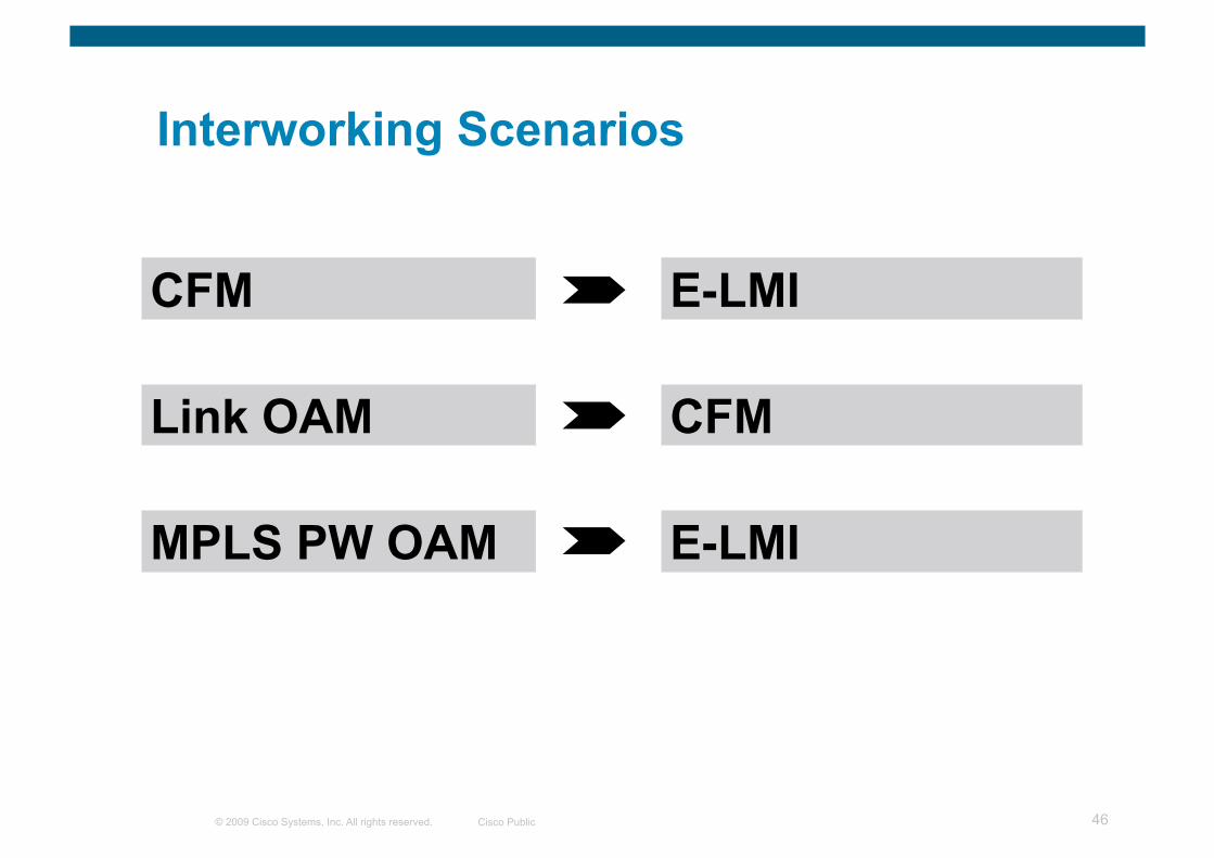
Interworking Scenarios
CFM
Link OAM
MPLS PW OAM
E-LMI
CFM
E-LMI
© 2009 Cisco Systems, Inc. All rights reserved. Cisco Public Presentation_ID 47
Fault Management Scenarios

© 2009 Cisco Systems, Inc. All rights reserved. Cisco Public 48
High Level Topology

© 2009 Cisco Systems, Inc. All rights reserved. Cisco Public 49
Fault Management Scenarios Number Description
1 End-to-End Service/Path Verification
Fault Verification/Isolation 2 Using E-OAM for Ethernet Access to L3VPN 3 E2E CPE Fault Notification & CPE Corrective Action
using Ethernet OAM Interworking 4 Ethernet OAM and MPLS OAM Interworking

© 2009 Cisco Systems, Inc. All rights reserved. Cisco Public 50
Operational Scenario 1
Problem Statement Fault Verification and Fault Isolation of ethernet connectivity issues
Problem Solution IEEE 802.1ag (CFM) Ping and Traceroute utilities for reactive
troubleshooting of service connectivity issues
Ethernet Access
MPLS Aggregation Ethernet
Access
Customer Service Provider
Customer Domain
Service Provider Domain
Operator Domain
CE 11 CE 31 uPE 31 nPE 31 nPE 11 uPE 11 PE-Agg

© 2009 Cisco Systems, Inc. All rights reserved. Cisco Public 51
Operational Scenario 1 (cont.)
Problem Statement Fault Verification and Fault Isolation of ethernet connectivity issues
Problem Solution IEEE 802.1ag (CFM) Ping and Traceroute utilities for reactive
troubleshooting of service connectivity issues
Ethernet Access
MPLS Core Ethernet Access
Customer Service Provider
Customer Domain
Service Provider Domain
Operator Domain
CE 11 CE 31 uPE 31 nPE 31 nPE 11 uPE 11 PE-Agg
uPE11#ping ethernet mpid 3100 level 4 vlan 100
Type escape sequence to abort. Sending 5 Ethernet CFM loopback messages, timeout is 2 seconds: !!!!! Success rate is 100 percent (5/5), round-trip min/avg/max = 1/1/1 ms
uPE11 uPE31

© 2009 Cisco Systems, Inc. All rights reserved. Cisco Public 52
Operational Scenario 1 (cont.)
Problem Statement Fault Verification and Fault Isolation of ethernet connectivity issues
Problem Solution IEEE 802.1ag (CFM) Ping and Traceroute utilities for reactive
troubleshooting of service connectivity issues
Ethernet Access
MPLS Core Ethernet Access
Customer Service Provider
Customer Domain
Service Provider Domain
Operator Domain
CE 11 CE 31 uPE 31 nPE 31 nPE 11 uPE 11 PE-Agg
uPE11#traceroute ethernet 0012.017c.3d00 level 4 vlan 100 Type escape sequence to abort. TTL 255. Per-Hop Timeout is 10 seconds Tracing the route to 0012.017c.3d00 on Domain PROVIDER_DOMAIN, Level 4, vlan 100 Traceroute sent via GigabitEthernet0/16
-------------------------------------------------------------------------------- MAC Ingress Ingress Action Relay Action Hops Host Forwarded Egress Egress Action Next Hop -------------------------------------------------------------------------------- B 1 nPE11 0013.5f21.cec5 Gi3/1 IngOk RlyCCDB Forwarded B 2 nPE31 0007.8508.3485 RlyFDB Forwarded Gi3/1 EgrOK uPE31 ! 3 uPE31 0012.017c.3d00 Gi1/1/1 IngOk RlyNone Not Forwarded
uPE11 uPE31 nPE11 nPE31

© 2009 Cisco Systems, Inc. All rights reserved. Cisco Public 53
Operational Scenario 1 (cont.)
Problem Statement Fault Verification and Fault Isolation of ethernet connectivity issues
Problem Solution IEEE 802.1ag (CFM) Ping and Traceroute utilities for reactive
troubleshooting of service connectivity issues
Ethernet Access
MPLS Core Ethernet Access
Customer Service Provider
Customer Domain
Service Provider Domain
Operator Domain
CE 11 CE 31 uPE 31 nPE 31 nPE 11 uPE 11 PE-Agg
Jan 26 03:14:10.608: %ETHER_SERVICE-6-EVC_STATUS_CHANGED: status of EVC_P2P_100 changed to InActive
uPE11#traceroute ethernet 0012.017c.3d00 level 4 vlan 100 Type escape sequence to abort. TTL 255. Per-Hop Timeout is 10 seconds Tracing the route to 0012.017c.3d00 on Domain PROVIDER_DOMAIN, Level 4, vlan 100 Traceroute sent via GigabitEthernet0/16
-------------------------------------------------------------------------------- MAC Ingress Ingress Action Relay Action Hops Host Forwarded Egress Egress Action Next Hop -------------------------------------------------------------------------------- B 1 nPE11 0013.5f21.cec5 Gi3/1 IngOk RlyCCDB Forwarded B 2 nPE31 0007.8508.3485 RlyCCDB Not Forwarded Gi3/1 EgrDown
nPE31(config)#int gig3/1 nPE31(config-if)#shutdown
X
Proactive Fault Notification
Reactive Fault Isolation
uPE11 uPE31 nPE11 nPE31

© 2009 Cisco Systems, Inc. All rights reserved. Cisco Public 54
Operational Scenario 2
Problem Statement Troubleshooting Ethernet access connectivity problems by L3VPN PE
Problem Solution IEEE 802.1ag CFM with Outward-facing / Down MEPs at L3VPN PE
MPLS Aggregation
Ethernet Access
Customer Service Provider
Customer Domain
Service Provider Domain
Operator Domain
CE 11 L3VPN PE nPE 21 nPE 11 uPE 11 PE-Agg

© 2009 Cisco Systems, Inc. All rights reserved. Cisco Public 55
Operational Scenario 2 (cont.)
Problem Statement Troubleshooting Ethernet access connectivity problems by L3VPN PE
Problem Solution IEEE 802.1ag CFM with Outward-facing / Down MEPs at L3VPN PE
Ethernet Access
MPLS Core Ethernet Access
Customer Service Provider
Customer Domain
Service Provider Domain
Operator Domain
CE 11 L3VPN PE uPE 21 nPE 21 nPE 11 uPE 11 PE-Agg
L3VPN-PE#show running-config | begin GigabitEthernet3/0/0 interface GigabitEthernet3/0/0 description L3VPN PE to nPE21 gig3/3 ethernet cfm mep level 4 outward domain PROVIDER_DOMAIN mpid 2450 vlan 450 ethernet cfm mep level 4 outward domain PROVIDER_DOMAIN mpid 2350 vlan 350 ! interface GigabitEthernet3/0/0.350 description To CE31 encapsulation dot1Q 350 ip vrf forwarding BLUE ip address 1.1.1.1 255.255.255.0 ! interface GigabitEthernet3/0/0.450 description To CE21 encapsulation dot1Q 450 ip vrf forwarding RED ip address 1.1.1.1 255.255.255.0
L3VPN-PE#show ethernet cfm maintenance-points remote Can only Ping/Traceroute to remote MEPs marked with *
MPID Level Mac Address Vlan PortState InGressPort Age(sec) Service ID 3350* 4 0012.017c.3d00 350 UP Gi3/0/0.350 20 customer_350_provider 2451* 4 0019.552c.0b80 450 UP Gi3/0/0.450 23 customer_450_provider

© 2009 Cisco Systems, Inc. All rights reserved. Cisco Public 56
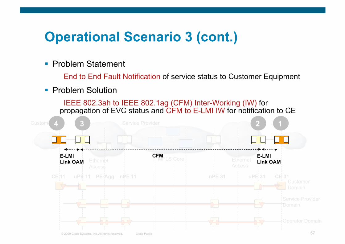
Operational Scenario 3
Problem Statement End to End Fault Notification of service status to Customer Equipment
Problem Solution IEEE 802.3ah to IEEE 802.1ag (CFM) Inter-Working (IW) for
propagation of EVC status and CFM to E-LMI IW for notification to CE
Ethernet Access
MPLS Aggregation
Ethernet Access
Customer Service Provider
Customer Domain
Service Provider Domain
Operator Domain
CE 11 CE 31 uPE 31 nPE 31 nPE 11 uPE 11 PE-Agg
© 2009 Cisco Systems, Inc. All rights reserved. Cisco Public 57
Operational Scenario 3 (cont.)
Problem Statement End to End Fault Notification of service status to Customer Equipment
Problem Solution IEEE 802.3ah to IEEE 802.1ag (CFM) Inter-Working (IW) for
propagation of EVC status and CFM to E-LMI IW for notification to CE
Ethernet Access
MPLS Core Ethernet Access
Customer Service Provider
Customer Domain
Service Provider Domain
Operator Domain
CE 11 CE 31 uPE 31 nPE 31 nPE 11 uPE 11 PE-Agg
1 4 3 2
CFM E-LMI Link OAM
E-LMI Link OAM

© 2009 Cisco Systems, Inc. All rights reserved. Cisco Public 58
Operational Scenario 3 (cont.)
Problem Statement End to End Fault Notification of service status to Customer Equipment
Problem Solution IEEE 802.3ah to IEEE 802.1ag (CFM) Inter-Working (IW) for
propagation of EVC status and CFM to E-LMI IW for notification to CE
Ethernet Access
MPLS Core Ethernet Access
Customer Service Provider
Customer Domain
Service Provider Domain
Operator Domain
CE 11 CE 31 uPE 31 nPE 31 nPE 11 uPE 11 PE-Agg CE31(config)#int fast 0/0 CE31(config-if)#shutdown
Jan 26 03:40:08.176: %ETHERNET_OAM-6-EXIT_SESSION: The client on interface Fa0/0 has left the OAM session. Jan 26 03:40:10.180: %LINK-5-CHANGED: Interface FastEthernet0/0, changed state to administratively down Jan 26 03:40:11.180: %LINEPROTO-5-UPDOWN: Line protocol on Interface FastEthernet0/0, changed state to down
X
1 4 3 2

© 2009 Cisco Systems, Inc. All rights reserved. Cisco Public 59
Operational Scenario 3 (cont.)
Problem Statement End to End Fault Notification of service status to Customer Equipment
Problem Solution IEEE 802.3ah to IEEE 802.1ag (CFM) Inter-Working (IW) for
propagation of EVC status and CFM to E-LMI IW for notification to CE
Ethernet Access
MPLS Core Ethernet Access
Customer Service Provider
Customer Domain
Service Provider Domain
Operator Domain
CE 11 CE 31 uPE 31 nPE 31 nPE 11 uPE 11 PE-Agg
Jan 26 03:40:08.176: %ETHERNET_OAM-6-RFI: The client on interface Fa1/0/1 has received a remote failure Indication from its remote peer (failure reason = remote client administratively turned off)
Jan 26 03:40:08.184: %ETHER_SERVICE-6-EVC_STATUS_CHANGED: status of EVC_P2P_100 changed to InActive Jan 26 03:40:09.191: %ETHERNET_OAM-6-EXIT_SESSION: The client on interface Fa1/0/1 has left the OAM session.
uPE31#show ethernet service evc Identifier Type Act-UNI-cnt Status EVC_P2P_100 P-P 1 InActive
uPE31#show ethernet lmi evc UNI Id: CE31_UNI St Evc Id CE-VLAN --- ---------------------------------------- ---------------------------------- ?I EVC_P2P_100 100
Key: St=Status, A=Active, P=Partially Active, I=Inactive, *=Default EVC, ?=Link Down
1 4 3 2

© 2009 Cisco Systems, Inc. All rights reserved. Cisco Public 60
Operational Scenario 3 (cont.)
Problem Statement End to End Fault Notification of service status to Customer Equipment
Problem Solution IEEE 802.3ah to IEEE 802.1ag (CFM) Inter-Working (IW) for
propagation of EVC status and CFM to E-LMI IW for notification to CE
Ethernet Access
MPLS Core Ethernet Access
Customer Service Provider
Customer Domain
Service Provider Domain
Operator Domain
CE 11 CE 31 uPE 31 nPE 31 nPE 11 uPE 11 PE-Agg
1 4 3 2
Jan 26 03:40:36.093: %ETHER_SERVICE-6-EVC_STATUS_CHANGED: status of EVC_P2P_100 changed to InActive
uPE11#show ethernet cfm maintenance-point remote MPID Level Mac Address Vlan PortState InGressPort Age(sec) Service ID 3100 4 0012.017c.3d00 100 DOWN Gi0/16 21 customer_100_provider
uPE11#show ethernet service evc Identifier Type Act-UNI-cnt Status EVC_P2P_100 P-P 1 InActive
uPE11#show ethernet lmi evc UNI Id: CE11_UNI St Evc Id CE-VLAN --- ---------------------------------------- ---------------------------------- I EVC_P2P_100 100
Key: St=Status, A=Active, P=Partially Active, I=Inactive, *=Default EVC, ?=Link Down

© 2009 Cisco Systems, Inc. All rights reserved. Cisco Public 61
Operational Scenario 3 (cont.)
Problem Statement End to End Fault Notification of service status to Customer Equipment
Problem Solution IEEE 802.3ah to IEEE 802.1ag (CFM) Inter-Working (IW) for
propagation of EVC status and CFM to E-LMI IW for notification to CE
Ethernet Access
MPLS Core Ethernet Access
Customer Service Provider
Customer Domain
Service Provider Domain
Operator Domain
CE 11 CE 31 uPE 31 nPE 31 nPE 11 uPE 11 PE-Agg
1 4 3 2
CE11#show ethernet lmi evc UNI Id: CE11_UNI St Evc Id CE-VLAN --- ---------------------------------------- ---------------------------------- I EVC_P2P_100 100
Key: St=Status, A=Active, P=Partially Active, I=Inactive, *=Default EVC, ?=Link Down
CE11#show ip interface brief Interface IP-Address OK? Method Status Protocol <snip> GigabitEthernet0/0.100 100.100.100.11 YES manual down down
Proactive E2E Fault Notification
Proactive CPE Action

© 2009 Cisco Systems, Inc. All rights reserved. Cisco Public 62
Problem Statement Troubleshooting Ethernet services over MPLS
Problem Solution CFM for detection, CFM and MPLS OAM for verification and
isolation
Operational Scenario 4 Ethernet and MPLS OAM
EoMPLS Pseudowire
MEP MIP

© 2009 Cisco Systems, Inc. All rights reserved. Cisco Public 63
ME3400G-2CS-1#show ethernet cfm errors Level Vlan MPID Remote MAC Reason Service ID 5 100 112 0019.30c0.ad80 Lifetime Timer Expir john-p2p
Operational Scenario 4 …Cont Ethernet and MPLS OAM
EoMPLS Pseudowire
Received SNMPv2c Trap: Community: TEST From: 127.0.0.1 sysUpTimeInstance = 668615 snmpTrapOID.0 = cEtherCfmCcMepDown cEtherCfmEventServiceId.1.3.40 = john-p2p cEtherCfmEventLclMacAddress.1.3.40 = 00 19 30 c0 bb 00 cEtherCfmEventLclMepCount.1.3.40 = 1 cEtherCfmEventLclIfCount.1.3.40 = 1 cEtherCfmEventRmtMepid.1.3.40 = 112 cEtherCfmEventRmtMacAddress.1.3.40 = 00 19 30 c0 ad 80 cEtherCfmEventCode.1.3.40 = 5

© 2009 Cisco Systems, Inc. All rights reserved. Cisco Public 64
ME3400G-2CS-1#ping ethernet 0019.30c0.ad80 level 5 vlan 100
Type escape sequence to abort. Sending 5 Ethernet CFM loopback messages, timeout is 2 seconds: ..... Success rate is 0 percent (0/5)
Operational Scenario 4 …Cont Ethernet and MPLS OAM
EoMPLS Pseudowire
ME3400G-2CS-1#traceroute ethernet 0019.30c0.ad80 level 5 vlan 100 Type escape sequence to abort. TTL 255. Per-Hop Timeout is 10 seconds Tracing the route to 0019.30c0.ad80 on Domain TEST-jose, Level 5, vlan 100 Traceroute sent via GigabitEthernet0/3
-------------------------------------------------------------------------------- MAC Ingress Ingress Action Relay Action Hops Host Forwarded Egress Egress Action Next Hop -------------------------------------------------------------------------------- B 1 ME3400G-1 0019.552b.df00 Gi0/3 IngOk RlyFDB Forwarded Gi0/14 EgrOK 7604-1 B 2 7604-1 0016.9c6e.7985 Gi2/0/2 IngOk RlyCCDB Forwarded * * *

© 2009 Cisco Systems, Inc. All rights reserved. Cisco Public 65
MPLS OAM Summary
Testing the Pseudo-Wire
R1#ping mpls pseudowire <IPv4 peer addr> <VC ID>
Testing the Transport LSP
R3#ping mpls ipv4 <IPv4 peer adr>

© 2009 Cisco Systems, Inc. All rights reserved. Cisco Public Presentation_ID 66
Ethernet Performance Management

© 2009 Cisco Systems, Inc. All rights reserved. Cisco Public 67
ITU-T Y.1731 Overview OAM Functions for Performance Management
ITU-T Y.1731 defines the PM functions and protocols to collect the performance data
Frame Loss Measurement (ETH-LM) Based on in-profile service frame counters (for P2P services only) Dual-ended ETH-LM (using CCM PDU) Single-ended ETH-LM (using LMM and LMR PDUs)
Frame Delay Measurement (ETH-DM) One-way ETH-DM (using 1DM PDU) Two-way ETH-DM (using DMM and DMR PDUs)
Synthetic Frame Loss Measurement (ETH-SLM) Proposal under discussion at ITU-T Covers P2P and MP services using synthetic traffic frame loss

© 2009 Cisco Systems, Inc. All rights reserved. Cisco Public 68
IP SLAs Performance Management
IP SLAs Embedded Policy Management Scheduling Automation/Policy Alerts/Data Collection
In-band Performance Management Tool for Ethernet Delay, Delay Variation and Packet Loss measurement Built in CFM principles
Automatic Discovery of Probe Endpoints
Cisco IP SLAs
CFM IP MPLS
Echo Probe Jitter Probe
Embedded Policy Management

© 2009 Cisco Systems, Inc. All rights reserved. Cisco Public 69
Deploying Carrier Ethernet OAM Ethernet Layer 2 VPN Services
IP SLA Ethernet “ECHO” probe Round Trip Time
IP SLA Ethernet “JITTER” probe One-way Delay One-Way Delay Variation One-way Packet Loss
End-to-end service performance management CE 11 CE 31 uPE 31 uPE 11 AGG 31 AGG 11
CFM LBM (with timestamps)
CFM LBR (with timestamps)
Vendor-specific CFM PDUs

© 2009 Cisco Systems, Inc. All rights reserved. Cisco Public 70
Deploying Carrier Ethernet OAM Ethernet Layer 2 VPN Services
End-to-end service performance management
ip sla ethernet-monitor 1 type echo domain PROVIDER_DOMAIN vlan 100 tag Dynamic-Echo-vid-100 owner Jose Liste
ip sla ethernet-monitor schedule 1 schedule-period 90 frequency 30 start-time now
ip sla ethernet-monitor 2 type jitter domain PROVIDER_DOMAIN vlan 100 num-frames 20 interval 10 tag Dynamic-Jitter-vid-100 owner Jose Liste
ip sla ethernet-monitor schedule 2 schedule-period 90 frequency 30 start-time now
Jitter Probe parameters: Vlan ID MEP ID (optional) Frequency Number of packets Inter-packet gap
Echo Probe parameters: Vlan ID MEP ID (optional) Frequency
Time
Time
CE 11 CE 31 uPE 31 uPE 11 AGG 31 AGG 11

© 2009 Cisco Systems, Inc. All rights reserved. Cisco Public Presentation_ID 71
Summary

© 2009 Cisco Systems, Inc. All rights reserved. Cisco Public 72
Summary
Ethernet OAM deliver equivalent function sets of legacy OAM and more to drive effective operations
You can perform fault, performance and configuration management with E-OAM
There are multiple suites of protocols from various standard bodies (& vendors) that work in different bucket
And they do interwork to give you a comprehensive troubleshooting and maintenance platform.

© 2009 Cisco Systems, Inc. All rights reserved. Cisco Public Presentation_ID 73
Questions?

© 2009 Cisco Systems, Inc. All rights reserved. Cisco Public 74
Acknowledgement
Jose Liste, Technical Marketing Engineer at Cisco Systems

© 2009 Cisco Systems, Inc. All rights reserved. Cisco Public 75

© 2009 Cisco Systems, Inc. All rights reserved. Cisco Public 76
Acronyms Acronym AIS Alarm Indication Signal
CCM Continuity Check Message
CCMDB CCM Data Base (see CCM)
CE Customer Edge
CFM Connectivity Fault Management
EFM Ethernet in the First Mile
E-LMI Ethernet LMI (see LMI)
E-OAM Ethernet OAM (see OAM)
EVC Ethernet Virtual Connection
IEEE Institute of Electrical and Electronics Engineers
ITU International Telecommunication Union
LBM Loopback Message
LBR Loopback Reply
LMI Local Management Interface
LTM Linktrace Message
LTR Linktrace Reply
MA Maintenance Association
MAID MA Identifier (see MA)
MD Maintenance Domain
Acronym MEF Metro Ethernet Forum
MEN Metro Ethernet Network
MEP Maintenance Association End Point
MEPID MEP Identifier (see MEP)
MHF MIP Half Function (see MIP)
MIB Management Information Base
MIP Maintenance Domain Intermediate Point
MP Maintenance Point
OAM Operations, Administration and Maintenance
PDU Protocol Data Unit
PE Provide Edge
RDI Remote Defect Indicator
RFI Remote Failure Indicator
TLV Type, Length, Value
UNI User to Network Interface
UNI-C Customer side of UNI (see UNI)
UNI-N Network side of UNI (see UNI)
VID VLAN Identifier
VLAN Virtual LAN

© 2009 Cisco Systems, Inc. All rights reserved. Cisco Public 77
Ethernet OAM
IEEE 802.1ag Connectivity Fault Management (CFM)
Also referred as Service OAM
IEEE 802.3ah (clause 57) Ethernet Link OAM
Also referred as 802.3 OAM, Link OAM or Ethernet in the First Mile (EFM) OAM
ITU-T Y.1731 OAM functions and mechanisms for Ethernet-based networks
MEF E-LMI Ethernet Local Management Interface

© 2009 Cisco Systems, Inc. All rights reserved. Cisco Public 78
IEEE 802.3ah OAM Events
Set of events that may impact link operation
Critical Link events Link fault—Fault in the Rx direction of local DTE
Dying gasp—Unrecoverable local failure condition
Critical event—Unspecified critical event
Link events Errored Symbol Period Event
Errored Frame Event
Errored Frame Period Event
Errored Frame Seconds Summary Event

© 2009 Cisco Systems, Inc. All rights reserved. Cisco Public 79
Ethernet LMI Periodic Polling and Asynchronous Update
Based on polling procedure invoked by CE
N391—Polling Counter, polling cycles between Full Status exchanges
N393—Status Counter, number of consecutive errors
T391—Polling Timer (PT), UNI-C transmits Status Enq.
T392—Polling Verification Timer (PVT), timer by which UNI-N expects to be polled
ELMI-CE (UNI-C) ELMI-PE (UNI-N) STATUS ENQ (Ethernet LMI Check) A
D
B STATUS (Ethernet LMI Check) C
STATUS ENQ (Ethernet LMI Check) STATUS (Ethernet LMI Check)
A
B C
STATUS ENQ (Full Status Req) STATUS (Full Status Resp)
A
B C
STATUS ENQ (Ethernet LMI Check) STATUS (Ethernet LMI Check)
A
B C
STATUS (EVC ASYNC Status) E
A T391 Expiry B Restart T391
C Restart T392 D N391 polls sent
E MEN Update

© 2009 Cisco Systems, Inc. All rights reserved. Cisco Public 80
MEP MEP MIP MIP
LMM
Customer Equipment
Customer Equipment
Operator A Bridges
Operator B Bridges
ITU-T Y.1731 Overview Single-Ended (On-demand) ETH-LM
LMR
LMM – Loss Measurement Message LMR – Loss Measurement Reply

© 2009 Cisco Systems, Inc. All rights reserved. Cisco Public 81
MEP MEP MIP MIP
DMM
Customer Equipment
Customer Equipment
Operator A Bridges
Operator B Bridges
ITU-T Y.1731 Overview Two-Way ETH-DM
DMR
DMM – Delay Measurement Message DMR – Delay Measurement Reply
RxTimestampf TxTimestampb Frame Delay =
(RxTimeb – TxTimesampf) – (TxTimestampb – RxTimesampf)
TxTimestamp

© 2009 Cisco Systems, Inc. All rights reserved. Cisco Public 82
Interworking Scenarios CFM to E-LMI
CFM @ Provider Level acts as MEN OAM: provides EVC Status and Remote UNI Status/Name to E-LMI
Interface Status TLV of CC Messages carry remote UNI status Cisco’s Organization-specific TLV of CC Messages carry remote UNI name Status of remote MEP in CCDB indicates EVC State
CE 11
CE
Ethernet Access
MPLS Aggregation
Ethernet Access
Service Layer OAM
Network Layer OAM
E-LMI
CE 31 uPE 31 nPE 31 nPE 11 uPE 11
Provider Level CFM
CFM to E-LMI I/W
Customer Service Provider

© 2009 Cisco Systems, Inc. All rights reserved. Cisco Public 83
Interworking Scenarios 802.3ah to CFM (CC-based)
Link Layer Defects detected by 802.3ah, relayed to CFM on same device CFM notifies remote devices of localized fault Two variants:
CC based (802.3ah on edge of domain) AIS based (802.3ah within domain)
CE 1
EthernetAccess
MPLS Aggregation Ethernet Access
CE 31 uPE 31 nPE 31 nPE 11 uPE 11
Customer Service Provider
PE-Agg Service
Layer OAM
Transport Layer OAM
CC
802.3ah 802.3ah to CFM I/W
CE

© 2009 Cisco Systems, Inc. All rights reserved. Cisco Public 84
Interworking Scenarios 802.3ah to CFM (AIS-based)
CE 1
EthernetAccess
MPLS Aggregation Ethernet Access
CE 31 uPE 31 nPE 31 nPE 11 uPE 11
Customer Service Provider
PE-Agg Service
Layer OAM
Transport Layer OAM
AIS AIS
802.3ah 802.3ah to CFM I/W
CE
Link Layer Defects detected by 802.3ah, relayed to CFM on same device CFM notifies remote devices of localized fault Two variants:
CC based (802.3ah on edge of domain) AIS based (802.3ah within domain)

© 2009 Cisco Systems, Inc. All rights reserved. Cisco Public 85
Interworking Scenarios MPLS PW OAM to E-LMI
Directed-LDP & VCCV (BFD mode) running between PEs D-LDP for defect notification, VCCV for defect detection Defects detected/communicated by PW OAM are relayed to E-LMI via I/W
function on PE
CE 1
CE
MPLS Core
Service Layer OAM
Transport Layer OAM
CE 2 PE A PE B
Customer Service Provider
VCCV-BFD D-LDP
E-LMI E-LMI
PW OAM to E-LMI I/W
Customer

© 2009 Cisco Systems, Inc. All rights reserved. Cisco Public 86
CFM Deployment Scenario A
Access 1 Access 2 Aggregation 1 Aggregation 2 CE1 CE2
Admin Domain “A”
End to End service provided over a single Administrative Domain (e.g. Carrier A)
Ethernet Aggregation

© 2009 Cisco Systems, Inc. All rights reserved. Cisco Public 87
CFM Deployment Scenario A (Cont.)
Customer Domain
SP Domain
Link Domain
MEP MIP
Access 1 Access 2 Aggregation 1 Aggregation 2 CE1 CE2
Ethernet Aggregation
Port MEPs First mile link monitoring
End to End SP service monitoring
End to End Customer service monitoring (optional)

© 2009 Cisco Systems, Inc. All rights reserved. Cisco Public 88
CFM Deployment Scenario B
Admin Domain “B” Admin Domain “A”
Access 1 Access 2 Aggregation 1 Aggregation 2 CE1 CE2
End to End service provided by a SP (e.g. Carrier A) who relies on another SP access network (e.g. Carrier B) to reach some customer sites
Ethernet Aggregation

© 2009 Cisco Systems, Inc. All rights reserved. Cisco Public 89
CFM Deployment Scenario B (Cont.)
Customer Domain
Operator Domain
MEP MIP
Access 1 Access 2 Aggregation 1 Aggregation 2 CE1 CE2
Ethernet Aggregation
Port MEPs E-NNI link monitoring
Independent Operator service monitoring
End to End Customer service monitoring (optional)
Link Domain

© 2009 Cisco Systems, Inc. All rights reserved. Cisco Public Presentation_ID 90
Fault Management Scenarios

© 2009 Cisco Systems, Inc. All rights reserved. Cisco Public 91
Deploying Carrier Ethernet OAM Ethernet Layer 2 VPN Services
Access Access Aggregation Aggregation CE CE
Point-to-Point Ethernet Service

© 2009 Cisco Systems, Inc. All rights reserved. Cisco Public 92
Deploying Carrier Ethernet OAM Ethernet Layer 2 VPN Services
Access Access Aggregation Aggregation CE CE
CFM E-LMI Link OAM E-LMI
Link OAM
OAM protocol positioning
CFM to E-LMI IW
CFM to E-LMI IW
Link OAM to CFM IW
Link OAM to CFM IW

© 2009 Cisco Systems, Inc. All rights reserved. Cisco Public 93
Deploying Carrier Ethernet OAM Ethernet Layer 2 VPN Services
CFM Continuity Check Messages (CCM)
UPE11#show ethernet cfm maintenance-points remote -------------------------------------------------------------------------------- MPID Domain Name MacAddress IfSt PtSt Lvl Domain ID Ingress RDI MA Name Type Id SrvcInst EVC Name Age -------------------------------------------------------------------------------- 3100 PROVIDER_DOMAIN aabb.cc00.0599 Up Up 4 PROVIDER_DOMAIN Et0/1.100 - customer_100_provider Vlan 100 N/A N/A 0s
Total Remote MEPs: 1
CCM Database
t0
t1
t2
CE 11 CE 31 uPE 31 uPE 11 AGG 31 AGG 11
Proactive End-to-End Service Monitoring

© 2009 Cisco Systems, Inc. All rights reserved. Cisco Public 94
Deploying Carrier Ethernet OAM Ethernet Layer 2 VPN Services
UPE11#ping ethernet mpid 3100 domain PROVIDER_DOMAIN vlan 100
Type escape sequence to abort. Sending 5 Ethernet CFM loopback messages to aabb.cc00.0599, timeout is 5 seconds :!!!!! Success rate is 100 percent (5/5), round-trip min/avg/max = 4/5/12 ms
CFM Loopback Message (LBM)
CFM Loopback Reply (LBR)
uPE11# ping ethernet
End-to-end Service/Failure Verification
CE 11 CE 31 uPE 31 uPE 11 AGG 31 AGG 11

© 2009 Cisco Systems, Inc. All rights reserved. Cisco Public 95
Deploying Carrier Ethernet OAM Ethernet Layer 2 VPN Services
CFM Linktrace Message (LTM) CFM Linktrace Reply (LTR)
uPE11# traceroute ethernet
Service Path Discovery/Failure Isolation
CE 11 CE 31 uPE 31 uPE 11 AGG 31 AGG 11

© 2009 Cisco Systems, Inc. All rights reserved. Cisco Public 96
Deploying Carrier Ethernet OAM Ethernet Layer 2 VPN Services
UPE11#traceroute ethernet mpid 3100 domain PROVIDER_DOMAIN vlan 100 Type escape sequence to abort. TTL 64. Linktrace Timeout is 5 seconds Tracing the route to aabb.cc00.0599 on Domain PROVIDER_DOMAIN, Level 4, vlan 100 Traceroute sent via Ethernet0/1.100, path found via MPDB
B = Intermediary Bridge ! = Target Destination * = Per hop Timeout -------------------------------------------------------------------------------- MAC Ingress Ingr Action Relay Action Hops Host Forwarded Egress Egr Action Previous Hop -------------------------------------------------------------------------------- B 1 AGG11 aabb.cc00.0399 Et0/0.100 IngOk RlyMPDB Forwarded Et0/1.100 EgrOK aabb.cc00.0299 B 2 AGG31 aabb.cc00.0499 Et0/0.100 IngOk RlyMPDB Forwarded Et0/1.100 EgrOK aabb.cc00.0399 ! 3 UPE31 aabb.cc00.0599 Et0/0.100 IngOk RlyHit:MEP Not Forwarded aabb.cc00.0499
uPE11# traceroute ethernet
Service Path Discovery/Failure Isolation
CE 11 CE 31 uPE 31 uPE 11 AGG 31 AGG 11

© 2009 Cisco Systems, Inc. All rights reserved. Cisco Public 97
Deploying Carrier Ethernet OAM Ethernet Layer 2 VPN Services
ELMI Status Enquiry message (Full Status report)
ELMI Status message (Full Status report)
Local UNI ID CE11_UNI CE-VLAN/EVC Map type Service_Multiplexing EVC ID EVC_P2P_100 EVC Type Point_to_Point CE-VLAN/EVC Map vlan 100 EVC Status New, Active Remote UNI count – configured 1 Remote UNI count – active 1 Remote UNI ID CE31_UNI Remote UNI status UP
Example:
CE Notification
CE 11 CE 31 uPE 31 uPE 11 AGG 31 AGG 11
Cisco enhancements to ELMI
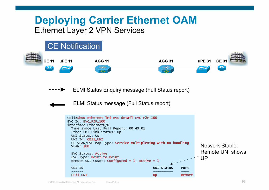
© 2009 Cisco Systems, Inc. All rights reserved. Cisco Public 98
Deploying Carrier Ethernet OAM Ethernet Layer 2 VPN Services
CE11#show ethernet lmi evc detail EVC_P2P_100 EVC Id: EVC_P2P_100 interface Ethernet0/0 Time since Last Full Report: 00:49:01 Ether LMI Link Status: Up UNI Status: Up UNI Id: CE11_UNI CE-VLAN/EVC Map Type: Service Multiplexing with no bundling VLAN: 100
EVC Status: Active EVC Type: Point-to-Point Remote UNI Count: Configured = 1, Active = 1
UNI Id UNI Status Port ------ ---------- ---- CE31_UNI Up Remote
ELMI Status Enquiry message (Full Status report)
ELMI Status message (Full Status report)
CE Notification
CE 11 CE 31 uPE 31 uPE 11 AGG 31 AGG 11
Network Stable: Remote UNI shows UP

© 2009 Cisco Systems, Inc. All rights reserved. Cisco Public 99
Deploying Carrier Ethernet OAM Ethernet Layer 2 VPN Services
CE Notification—VLAN ID Missmatch
CE 11 CE 31 uPE 31 uPE 11 AGG 31 AGG 11
CE11(config)#interface gig0/0.100 CE11(config-subif)#encapsulation dot1Q 100
CE11#show ip interface brief Interface IP-Address OK? Method Status Protocol <snip> GigabitEthernet0/0.100 100.100.100.11 YES NVRAM up up
CE Configured with the correct C-VLAN (e.g. vid 100)

© 2009 Cisco Systems, Inc. All rights reserved. Cisco Public 100
Deploying Carrier Ethernet OAM Ethernet Layer 2 VPN Services
CE Notification—VLAN ID Missmatch
CE 11 CE 31 uPE 31 uPE 11 AGG 31 AGG 11
CE Configured with the incorrect C-VLAN (e.g. vid 1300)
CE11(config)#interface gig0/0.100 CE11(config-subif)#encapsulation dot1Q 1300
Jan 26 00:15:39.546: %ETHER_LMI-6-MISMATCHED_VLAN_NOT_CONFIGURED: VLAN 100 not Configured but in VLAN mapping for UNI GigabitEthernet0/0
Jan 26 00:15:39.546: %ETHER_LMI-6-MISMATCHED_VLAN_CONFIGURED: VLAN 1300 configured but not in VLAN mapping for UNI GigabitEthernet0/0 Interface
CE11#show ip interface brief Interface IP-Address OK? Method Status Protocol <snip> GigabitEthernet0/0.100 100.100.100.11 YES NVRAM down down
Proactive ELMI Action at CPE

© 2009 Cisco Systems, Inc. All rights reserved. Cisco Public 101
Deploying Carrier Ethernet OAM Ethernet Layer 2 VPN Services
Access Access Aggregation
ELMI Status message Async EVC report
ELMI Status message Async EVC report
ELMI action: CE brings down (sub)interface
ELMI action: CE brings down (sub)interface
CFM remote MEP timeout
MEP Down (timeout) alarm DefRemoteCCM IEEE alarm EVC declared Inactive CFM to ELMI Interworking
CFM remote MEP timeout
MEP Down (timeout) alarm DefRemoteCCM IEEE alarm EVC declared Inactive CFM to ELMI Interworking
Failure Scenario: Network Failure
Aggregation X
CE CE

© 2009 Cisco Systems, Inc. All rights reserved. Cisco Public 102
Deploying Carrier Ethernet OAM Ethernet Layer 2 VPN Services
UPE11#
*Apr 8 04:33:44.911: %E_CFM-3-REMOTE_MEP_DOWN: Remote MEP mpid 3100 vlan 100 MA name customer_100_provider in domain PROVIDER_DOMAIN changed state to down with event code TimeOut.
*Apr 8 04:33:44.911: %ETHER_SERVICE-6-EVC_STATUS_CHANGED: status of EVC_P2P_100 changed to InActive
*Apr 8 04:33:47.587: %E_CFM-3-FAULT_ALARM: A fault has occurred in the network for the local MEP having mpid 1100 vlan 100 for service MA name customer_100_provider with the event code DefRemoteCCM.
UPE11#show ethernt cfm errors -------------------------------------------------------------------------------- MPID Domain Id Mac Address Type Id Lvl MAName Reason Age -------------------------------------------------------------------------------- 3100 PROVIDER_DOMAIN aabb.cc00.0599 Vlan 100 4 customer_100_provider Lifetime Timer Expired 119s
CE 11 CE 31 uPE 31 uPE 11
X AGG 31 AGG 11
Error DB
IEEE-defined alarm
Cisco-defined alarm

© 2009 Cisco Systems, Inc. All rights reserved. Cisco Public 103
Deploying Carrier Ethernet OAM Ethernet Layer 2 VPN Services
UPE11#ping ethernet aabb.cc00.0599 domain PROVIDER_DOMAIN vlan 100
Type escape sequence to abort. Sending 5 Ethernet CFM loopback messages to aabb.cc00.0599, timeout is 5 seconds :..... Success rate is 0 percent (0/5)
UPE11#traceroute ethernet aabb.cc00.0599 domain PROVIDER_DOMAIN vlan 100 Type escape sequence to abort. TTL 64. Linktrace Timeout is 5 seconds Tracing the route to aabb.cc00.0599 on Domain PROVIDER_DOMAIN, Level 4, vlan 100 Traceroute sent via Ethernet0/1.100, path found via MPDB
B = Intermediary Bridge ! = Target Destination * = Per hop Timeout -------------------------------------------------------------------------------- MAC Ingress Ingr Action Relay Action Hops Host Forwarded Egress Egr Action Previous Hop -------------------------------------------------------------------------------- B 1 AGG11 aabb.cc00.0399 Et0/0.100 IngOk RlyMPDB Forwarded Et0/1.100 EgrOK aabb.cc00.0299 * * * *
CE 11 CE 31 uPE 31 uPE 11
X AGG 31 AGG 11

© 2009 Cisco Systems, Inc. All rights reserved. Cisco Public 104
Deploying Carrier Ethernet OAM Ethernet Layer 2 VPN Services
CE11#
*Apr 8 04:33:44.991: %LINEPROTO-5-UPDOWN: Line protocol on Interface Ethernet0/0.100, changed state to down
CE11#show ethernet lmi evc detail EVC_P2P_100 EVC Id: EVC_P2P_100 interface Ethernet0/0 Time since Last Full Report: 00:01:13 Ether LMI Link Status: Up UNI Status: Up UNI Id: CE11_UNI CE-VLAN/EVC Map Type: Service Multiplexing with no bundling VLAN: 100
EVC Status: Inactive EVC Type: Point-to-Point Remote UNI Count: Configured = 1, Active = 0
UNI Id UNI Status Port ------ ---------- ---- CE31_UNI Unreachable Remote
CE 11 CE 31 uPE 31 uPE 11
X AGG 31 AGG 11
Network Failure: Remote UNI shows UNREACHABLE

© 2009 Cisco Systems, Inc. All rights reserved. Cisco Public 105
Deploying Carrier Ethernet OAM Ethernet Layer 2 VPN Services
UNI Link Down
ELMI action: CE brings down (sub)interface
ELMI Status message Async EVC report
CFM MEP Up (port state Down) alarm DefMACstatus IEEE alarm EVC declared Inactive CFM to ELMI InterWorking
EVC declared Inactive
CFM CCM Interface Status TLV “isDown”
X
Failure Scenario: UNI Link Down
Access Access Aggregation Aggregation CE CE

© 2009 Cisco Systems, Inc. All rights reserved. Cisco Public 106
Deploying Carrier Ethernet OAM Ethernet Layer 2 VPN Services
UPE11#
*Apr 8 04:41:54.823: %E_CFM-6-REMOTE_MEP_UP: Continuity Check message is received from a remote MEP with mpid 3100 vlan 100 MA name customer_100_provider domain PROVIDER_DOMAIN interface status Down event code PortState.
*Apr 8 04:41:54.823: %ETHER_SERVICE-6-EVC_STATUS_CHANGED: status of EVC_P2P_100 changed to InActive
*Apr 8 04:41:57.451: %E_CFM-3-FAULT_ALARM: A fault has occurred in the network for the local MEP having mpid 1100 vlan 100 for service MA name customer_100_provider with the event code DefMACstatus.
UPE11#show ethernet cfm maintenance-point remote -------------------------------------------------------------------------------- MPID Domain Name MacAddress IfSt PtSt Lvl Domain ID Ingress RDI MA Name Type Id SrvcInst EVC Name Age -------------------------------------------------------------------------------- 3100 PROVIDER_DOMAIN aabb.cc00.0599 Down Up 4 PROVIDER_DOMAIN Et0/1.100 - customer_100_provider Vlan 100 N/A N/A 0s
Total Remote MEPs: 1
X CE 11 CE 31 uPE 31 uPE 11 AGG 31 AGG 11

© 2009 Cisco Systems, Inc. All rights reserved. Cisco Public 107
Deploying Carrier Ethernet OAM Ethernet Layer 2 VPN Services
CE11#
*Apr 8 04:41:54.907: %LINEPROTO-5-UPDOWN: Line protocol on Interface Ethernet0/0.100, changed state to down
CE11#show ethernet lmi evc detail EVC_P2P_100 EVC Id: EVC_P2P_100 interface Ethernet0/0 Time since Last Full Report: 00:01:07 Ether LMI Link Status: Up UNI Status: Up UNI Id: CE11_UNI CE-VLAN/EVC Map Type: Service Multiplexing with no bundling VLAN: 100
EVC Status: Inactive EVC Type: Point-to-Point Remote UNI Count: Configured = 1, Active = 0
UNI Id UNI Status Port ------ ---------- ---- CE31_UNI Down Remote
X CE 11 CE 31 uPE 31 uPE 11 AGG 31 AGG 11
UNI Failure: Remote UNI shows DOWN

© 2009 Cisco Systems, Inc. All rights reserved. Cisco Public 108
Deploying Carrier Ethernet OAM Ethernet Layer 2 VPN Services
UNI admin Shutdown at CE
CE transmits 802.3ah Dying Gasp
ELMI action: CE brings down (sub)interface
ELMI Status message Async EVC report
CFM MEP Up (port state AdminDown) alarm DefMACstatus IEEE alarm EVC declared Inactive CFM to ELMI InterWorking
802.3ah alarm EVC declared Inactive 802.3ah to CFM InterWorking
X
Failure Scenario: UNI Admin Shutdown
Access Access Aggregation Aggregation CE CE
CFM CCM Organization-specific TLV AdminDown
Cisco enhancement to CFM

© 2009 Cisco Systems, Inc. All rights reserved. Cisco Public 109
Deploying Carrier Ethernet OAM Ethernet Layer 2 VPN Services
Power lost at CE site
CE transmits Power Failure 802.3ah Dying Gasp
ELMI action: CE brings down (sub)interface
ELMI Status message Async EVC report
CFM MEP Up (port state Down) alarm DefMACstatus IEEE alarm EVC declared Inactive CFM to ELMI InterWorking
802.3ah alarm EVC declared Inactive 802.3ah to CFM InterWorking
Failure Scenario: Power Failure at CE
Access Access Aggregation Aggregation CE CE
CFM CCM Interface Status TLV “isDown”
X
© 2009 Cisco Systems, Inc. All rights reserved. Cisco Public 110
Deploying Carrier Ethernet OAM Ethernet Layer 2 VPN Services
CE exceeds 802.3ah HIGH error threshold
CE sends 802.3ah Event OAM PDUs
ELMI action: CE brings down (sub)interface
ELMI Status message Async EVC report
CFM MEP Up (port state remoteExcessiveErrors) alarm EVC declared Inactive CFM to ELMI InterWorking
802.3ah to CFM InterWorking EVC declared Inactive
Failure Scenario: UNI Errors (Detected by CE)
X
Receive Errors detected by CE
Access Access Aggregation Aggregation CE CE
CFM CCM Organization-specific TLV remoteExcessiveErrors
Cisco enhancement to CFM

© 2009 Cisco Systems, Inc. All rights reserved. Cisco Public 111
Deploying Carrier Ethernet OAM Ethernet Layer 2 VPN Services
SP exceeds 802.3ah HIGH error threshold
SP sends 802.3ah Event OAM PDUs
ELMI action: CE brings down (sub)interface
ELMI Status message Async EVC report
CFM MEP Up (port state localExcessiveErrors) alarm EVC declared Inactive CFM to ELMI InterWorking
802.3ah to CFM InterWorking EVC declared Inactive
Failure Scenario: UNI Errors (detected by SP)
X Access Access Aggregation Aggregation CE CE
CFM CCM Organization-specific TLV localExcessiveErrors
Cisco enhancement to CFM
Receive Errors detected by SP

© 2009 Cisco Systems, Inc. All rights reserved. Cisco Public 112
Deploying Carrier Ethernet OAM Ethernet Layer 2 VPN Services
CE CE PE PE EoMPLS Pseudowire
Point-to-Point Ethernet Service

© 2009 Cisco Systems, Inc. All rights reserved. Cisco Public 113
Deploying Carrier Ethernet OAM Ethernet Layer 2 VPN Services
CE CE PE PE EoMPLS Pseudowire
Directed LDP session E-LMI E-LMI
OAM Protocol Positioning
PW OAM To E-LMI IW
PW OAM To E-LMI IW

© 2009 Cisco Systems, Inc. All rights reserved. Cisco Public 114
Deploying Carrier Ethernet OAM Ethernet Layer 2 VPN Services
CE CE PE PE EoMPLS Pseudowire
CE UNI failure: Admin “shutdown”
ELMI action: CE brings down (sub)interface
ELMI Status message Async EVC report
PW declared DOWN (syslog) EVC declared Inactive (syslog) PW OAM to ELMI InterWorking
EVC declared Inactive PW declared DOWN (syslog)
Tx LDP TLV Status (PW status: AC DOWN)
X
Failure Scenario: UNI Failure
© 2009 Cisco Systems, Inc. All rights reserved. Cisco Public 115
ITU-T Y.1731 Terminology Comparison with IEEE 802.1ag
IEEE 802.1ag ITU-T Y.1731 ME Maintenance Entity ME Maintenance Entity
MA Maintenance Association MEG ME Group
MAID MA Identifier MEGID MEG Identifier
MD Maintenance Domain --- No such construct available
MD Level MD Level MEG
Level MEG Level
MEP MA End Point MEP MEG End Point
MIP MD Intermediate Point MIP MEG Intermediate Point
--- No such construct available
Server MEP Server MEP


![MEF 36 - Service OAM SNMP MIB for Performance Monitoring · PDF fileService OAM SNMP MIB for Performance Monitoring ... OSS Operations Support System ITU-T Y.1731 [20] PDU Protocol](https://img.pdfslide.net/doc/110x75/5aae9a177f8b9a190d8c51aa/mef-36-service-oam-snmp-mib-for-performance-monitoring-oam-snmp-mib-for-performance.jpg)