Embed Size (px)
Citation preview

Euro-Norm grease separators FROM KESSEL
Grease
Separators
Polyethylene grease separators according to EuroNorm EN 1825
Leading in drainage
Page 2
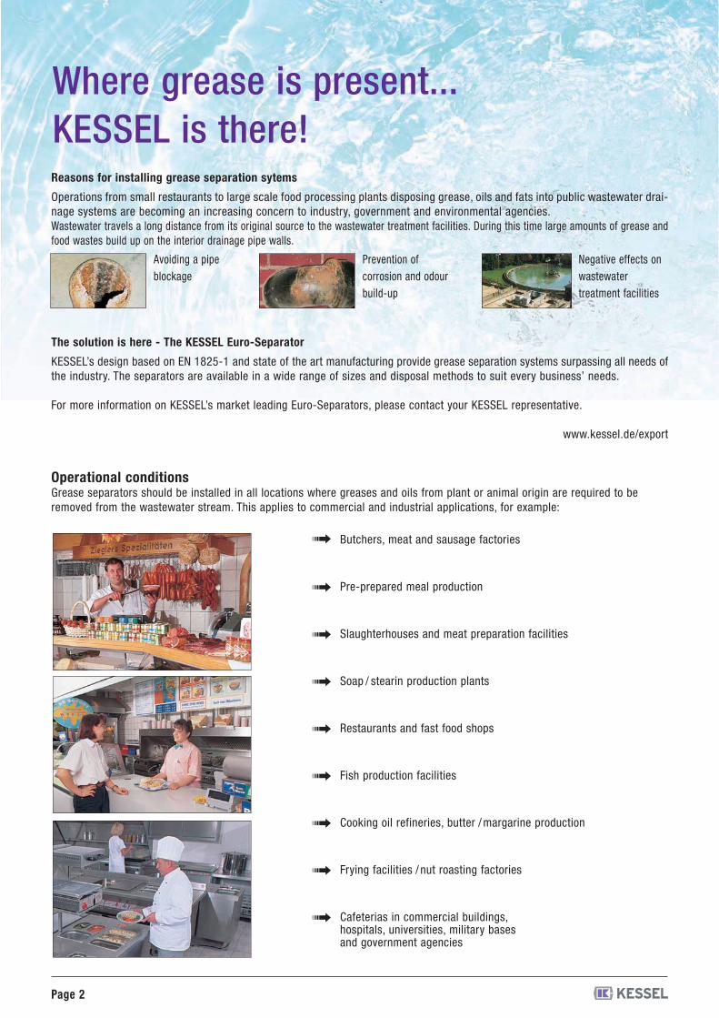
Where grease is present...KESSEL is there!
Butchers, meat and sausage factories
Pre-prepared meal production
Slaughterhouses and meat preparation facilities
Soap / stearin production plants
Restaurants and fast food shops
Fish production facilities
Cooking oil refineries, butter /margarine production
Frying facilities / nut roasting factories
Cafeterias in commercial buildings,hospitals, universities, military basesand government agencies
�
�
�
�
�
�
�
�
�
Operational conditionsGrease separators should be installed in all locations where greases and oils from plant or animal origin are required to beremoved from the wastewater stream. This applies to commercial and industrial applications, for example:
Reasons for installing grease separation sytems
Operations from small restaurants to large scale food processing plants disposing grease, oils and fats into public wastewater drai-nage systems are becoming an increasing concern to industry, government and environmental agencies.Wastewater travels a long distance from its original source to the wastewater treatment facilities. During this time large amounts of grease andfood wastes build up on the interior drainage pipe walls.
The solution is here - The KESSEL Euro-Separator
KESSEL’s design based on EN 1825-1 and state of the art manufacturing provide grease separation systems surpassing all needs ofthe industry. The separators are available in a wide range of sizes and disposal methods to suit every business’ needs.
For more information on KESSEL’s market leading Euro-Separators, please contact your KESSEL representative.
www.kessel.de/export
Avoiding a pipeblockage
Prevention ofcorrosion and odourbuild-up
Negative effects onwastewatertreatment facilities
pages 4 - 5 Selection Criteria and Product Advantages
page 6 Separator Function
1 General Information
pages 8 - 9 Grease Separator Euro “E + S” PV
pages 10 - 11 Grease Separator Euro “E + S” M
pages 12 - 13 Grease Separator Euro “D + S-P1”
pages 14 - 15 Grease Separator Euro “D + S”
pages 16 - 17 Grease Separator Euro “D”
pages 18 -19 Grease Separator Euro “G” NS 2 / 4 / 7 / 10
page 20 Grease Separator SE CNS NS 2 - 25
page 21 Grease Separator “Under sink”
page 22 Grease Separator Euro “G” NS 0,25 / 0,5 / 1
pages 23 - 26 Accessories
pages 28 - 29 Grease Separator Euro “G” NS 1 / 2 / 4
page 30 Grease Separator Euro “G” NS 7 - 35
page 31 Grease Separator “G” round
pages 32 - 33 Accessories
pages 34 - 38 Size Calculation
2 Grease Separatorsfor Interior Installation
3 Grease Separatorsfor Underground Installation
4 Technical Information
Page 3
Content

Page 4
Selection Criteria
Product Advantages
KESSEL has been manufacturing draining systems made ofpolymer for a long time. “The certification confirms ourinnovative strength, the high level of quality of our pro-ducts and synthetic material as the material of the future.”
The German Institute for Structural Engineering (DIBt) hasgranted site-inspection certification. This makes KESSEL thefirst manufacturer on the German market to be granted suchan inspection certificate.
“The polyethylene material creates significant advantagesfor planners, decision makers and processing workers,such as long-term watertightness and fracture resistance,the relatively low weight, short installation times and lastbut not least an attractive price.”
KESSEL extends the warranty period for tanksand upper sections beyond thestatutory requirement to 20 years.This covers the watertightness,usability and static safety ofthese components.
Simple and fast installationThanks to the low weight and straightforward KESSEL fasteningtechnology, the KESSEL round-design grease separator system caneasily be dismantled to minimum component size, allowing it tobe set up in rooms with only very narrow access.
Odour-proofThe single-piece grease separator tank made of polyethylene isboth gas and waterproof. The covers are sealed tight with a sea-ling ring and fast-action clamp.
Resistant to aggressive fatty acidsThe polyethylene material used guarantees a long service life sincethere is no early damage to the material e.g. through corrosion.
Compact design, low weightMinimum dimensions mean easy installatione.g. via narrow stairs into cramped cellarrooms where there is little installationspace.
Polyet
hylene Warranty
Polyet
hylene Warranty
20 Years
Fully automated operationOdour free disposal and cleaningMixing of separator contentswith Shredder-Mix-SystemOptimal cleaning with only a single pumpOptional remote control
Grease Separator “E+S” PV
Odour free disposal and cleaningMixing of separator contentswith Shredder-Mix-SystemComplete cleaningof interior separator wallsDisposal through pre-installeddisposal pipe by pumpSimple On / Off controlManual change-over from mixingto disposal
Grease Separator “E+S” M
Odour free disposal and cleaningMixing of separator contentswith Shredder-Mix-SystemSimple controlsNo warm water connection necessaryDisposal through pre-installed disposal pipeFully automated operation exceptfor disposal (version D+S-P1)
Grease Separator D+S / D+S-P1
Products see pages 12-15Product see page 10-11Product see page 8-9

Page 5
Grease separators made of polymer
Easy transportTheir low weight allows KESSEL greaseseparators to be transported easily. Thespecial base structure of the separatorsallows problem-free transport by meansof a forklift.
Telescopic upper section is standardFor installation of the tank in the ground, theupper section can be vertically adjusted by upto 500 mm and tilted through up to 5° for adap-tation to the ground level. The odour-proofcovers are available in the load classes A/B, D.
Absolutely tightPE-HD is absolutely waterproof. The individualelements and pipe connections are sealed usingsealing rings according to DIN EN 681-1 whichseal both axially and radially, thus guaranteeinga high degree of safety.
Closed cover disposalOdour free disposal possiblewith non-solidified greasesCleaning possible with open coversDisposal through pre-installed disposal pipe
Grease Separator D
for free standing orunderground installation
Low cost modelNS 1 to NS 35Disposal with open coversDisposal system available upon request
Grease Separator G
Regular disposal of grease and sludgeeven during separator operationSeparate disposal of grease and sludgeEnvironmentally friendly recyclingof collected wasteDisposal costs reduced since cleanwater remains in separator, only greaseand sludge are removedDisposal requires no additional water forrinsing, cleaning or re-filling which savesvaluable drinking waterOn-site assembly available
Grease Separator SE CNS
SPÜLEN
EINAUS
MOTORSCHUTZ
HEIZREGLER
MOTORSCHUTZ
HEIZEN
MISCHEN
Product see page 20Products see pages 18-19 and 28-31Product see page 16-17
Easy to cleanCrust formation on the walls is prevented by thesurface finish, which is similar to wax. The systemis easy to clean, leading to shorter disposal timesand lower cleaning water consumption.
SonicControl level sensing systemwith ultra sonic sensorfor the measurement,display and control ofthe grease layer thicknessin a grease separator
Disposal costs are savedby extending the disposal intervals.
Environment protectionDisposal of clean water no longer necessary,takes the pressure off resources.
User-friendly operationthanks to the interactive control unit with digitaldisplay and userfriendly interface.
Product see page 23
Page 6
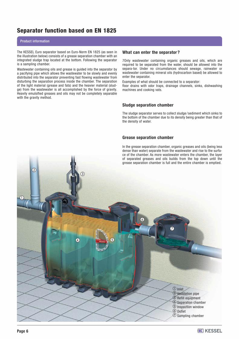
Separator function based on EN 1825
The KESSEL Euro separator based on Euro-Norm EN 1825 (as seen inthe illustration below) consists of a grease separation chamber with anintegrated sludge trap located at the bottom. Following the separatoris a sampling chamber.
Wastewater containing oils and grease is guided into the separator bya pacifying pipe which allows the wastewater to be slowly and evenlydistributed into the separator preventing fast flowing wastewater fromdisturbing the separation process inside the chamber. The separationof the light material (grease and fats) and the heavier material (slud-ge) from the wastewater is all accomplished by the force of gravity.Heavily emulsified greases and oils may not be completely separablewith the gravity method.
What can enter the separator ?
7Only wastewater containing organic greases and oils, which arerequired to be separated from the water, should be allowed into thesepara-tor. Under no circumstances should sewage, rainwater orwastewater containing mineral oils (hydrocarbon based) be allowed toenter the separator.Examples of what should be connected to a separator:floor drains with odor traps, drainage channels, sinks, dishwashingmachines and cooking vats.
Sludge separation chamber
The sludge separator serves to collect sludge / sediment which sinks tothe bottom of the chamber due to its density being greater than that ofthe density of water.
Grease separation chamber
In the grease separation chamber, organic greases and oils (being lessdense than water) separate from the wastewater and rise to the surfa-ce of the chamber. As more wastewater enters the chamber, the layerof separated greases and oils builds from the top down until thegrease separation chamber is full and the entire chamber is emptied.
�
��
� �
�
�
�������
InletVentilation pipeRefill equipmentSeparation chamberInspection windowOutletSampling chamber
Product information
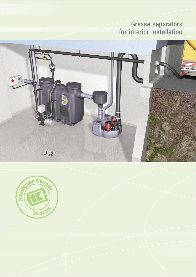
Grease separatorsfor interior installation
PPoollyy
eetthhyy
lleennee WWaaW rrrraannttyytt
20 Years
Page 8
Article descriptionIllustration
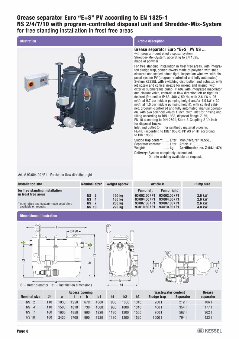
Grease separator Euro “E+S” PV according to EN 1825-1NS 2/4/7/10 with program-controlled disposal unit and Shredder-Mix-Systemfor free standing installation in frost free areas
bb1
�420l
a
h2 h1h3
� �Dimensioned illustration
Ø = Outer diameter b1 = Installation dimensions
Ø
110110160160
a
1030150016002430
b
670730990990
h1
930930
11301130
h2
1000100012001200
h3
1310131015601560
l
1250181018502700
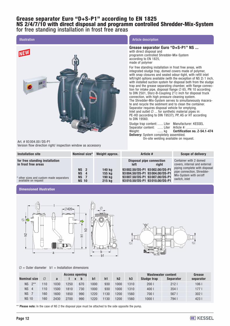
Sludge trap
200 l400 l700 l
1000 l
Wastewater contentSeparator
212 l354 l567 l794 l
Greaseseparator
106 l177 l302 l423 l
Nominal size
NS 2NS 4NS 7NS 10
b1
1000100012201220
xAccess opening
Art. # 93 004.00 / P1 Version in flow direction right
Nominal size* Article #
NS 2NS 4NS 7NS 10
150 kg165 kg200 kg225 kg
* other sizes and custom-made separatorsavailable on request
for free standing installationin frost free areas
Installation site
93 002.50 / P193 004.50 / P193 007.50 / P193 010.50 / P1
93 002.00 / P193 004.00 / P193 007.00 / P193 010.00 / P1
Pump left Pump right
Pump size
2.6 kW2.6 kW2.6 kW4.0 kW
Grease separator Euro “E+S” PV NS ...with program-controlled disposal system,Shredder-Mix-System, according to EN 1825,made of polymerFor free standing installation in frost free areas, with integra-ted sludge trap, domed covers made of polymer, with snapclosures and sealed odour-tight, inspection window, with dis-posal system PV (program-controlled and fully automated)System KESSEL with switching distribution and actuator, withjet nozzle and conical nozzle for mixing and rinsing, withexterior submersible pump (IP 68), with integrated maceratorand closure valve, controls in flow direction left or right asdesired (Protection IP 68, 400 V, 50 Hz, with 2.6 kW > 25m3/h at 0.7 bar middle pumping height and/or 4.0 kW > 30m3/h at 1.0 bar middle pumping height), with control cabi-net, program-controlled and fully automated, manual operati-on, with two solenoid valves 1 inch, with inlet for rinsing andfilling according to DIN 1988, disposal flange Ø 65,PN 10 according to DIN 2501, Storz-B-Coupling 2 1/2 inchfor disposal trucks.Inlet and outlet Ø ... for synthetic material pipes in:PE-HD (according to DIN 19537); PP, AS or HT accordingto DIN 19560.Sludge trap content:...... Liter Manufacturer: KESSELSeparator content: ...... Liter Article #: ........................Weight: ...... kg Certification no. Z-54.1-474Delivery: System completely assembled.
On-site welding available on request.
Weight approx.
Page 9
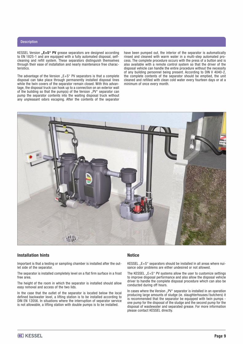
Installation hints
Important is that a testing or sampling chamber is installed after the out-let side of the separator.
The separator is installed completely level on a flat firm surface in a frostfree area.
The height of the room in which the separator is installed should alloweasy removal and access of the two lids.
In the case that the outlet of the separator is located below the localdefined backwater level, a lifting station is to be installed according toDIN EN 12056. In situations where the interruption of separator serviceis not allowable, a lifting station with double pumps is to be installed.
Notice
KESSEL „E+S“ separators should be installed in all areas where nui-sance odor problems are either undesired or not allowed.
The KESSEL „E+S“ PV systems allow the user to customize settingsto improve disposal performance and also allow the disposal vehicledriver to handle the complete disposal procedure which can also beconducted during off hours.
In cases where the Version „PV“ separator is installed in an operationproducing large amounts of sludge (ie. slaughterhouses /butchers) itis recommended that the separator be equipped with twin pumps -one pump for the disposal of the sludge and the second pump for thedisposal of wastewater and separated grease. For more informationplease contact KESSEL directly.
KESSEL Version „E+S“ PV grease separators are designed accordingto EN 1825-1 and are equipped with a fully automated disposal, self-cleaning and refill system. These separators distinguish themselvesthrough their ease of installation and nearly maintenance free charac-teristics.
The advantage of the Version „E+S“ PV separators is that a completedisposal can take place through permanently installed disposal lineswhile the twin covers of the separator remain closed. With this advan-tage, the disposal truck can hook up to a connection on an exterior wallof the building so that the pump(s) of the Version „PV“ separator canpump the separator contents into the waiting disposal truck withoutany unpleasant odors escaping. After the contents of the separator
have been pumped out, the interior of the separator is automaticallyrinsed and cleaned with warm water in a multi-step automated pro-cess. The complete procedure occurs with the press of a button and isalso available with a remote control system so that the driver of thedisposal vehicle can handle the entire procedure without the necessityof any building personnel being present. According to DIN V 4040-2,the complete contents of the separator should be emptied, the unitcleaned and refilled with clean cold water every fourteen days or at aminimum of once every month.
Description

Page 10
Article descriptionIllustration
Grease separator Euro “E+S” M according to EN 1825-1NS 2/4/7/10 with manual system and Shredder-Mix-Systemfor free standing installation in frost free areas
Grease separator Euro “E+S” M NS ...with manually controlled disposal system,Shredder-Mix-System, according to EN 1825,made of polymerFor free standing installation in frost free areas, with integra-ted sludge trap, domed covers made of polymer, with snapclosures and sealed odour-tight, inspection window, with(manual) disposal system M System KESSEL with switchingdistribution, with jet nozzle and conical nozzle for mixing andrinsing, with exterior submersible pump (IP 68), with integra-ted macerator and closure valve, controls in flow directionleft or right as desired (Protection IP 68, 400 V, 50 Hz, with2.6 kW > 25 m3/h at 0.7 bar middle pumping height and/or4.0 kW > 30 m3/h at 1.0 bar middle pumping height), withcontrol cabinet, with inlet for rinsing and filling accordingto DIN 1988, disposal flange Ø 65, PN 10 according toDIN 2501, Storz-B-Coupling 2 1/2 inch for disposal trucks.Inlet and outlet Ø ... for synthetic material pipes in:PE-HD (according to DIN 19537); PP, AS or HT accordingto DIN 19560.Sludge trap content:...... Liter Manufacturer: KESSELSeparator content: ...... Liter Article #: .......................Weight: ...... kg Certification no. Z-54.1-474Delivery: System completely assembled.
On-site welding available on request.
Art. # 93 004.00/M1 Version in flow direction right
bb1
�420l
a
h2 h1h3
� �Dimensioned illustration
Nominal size* Article #
NS 2NS 4NS 7NS 10
140 kg155 kg190 kg215 kg
for free standing installationin frost free areas
Installation site
93 002.50/M193 004.50/M193 007.50/M193 010.50/M1
93 002.00 /M193 004.00 /M193 007.00 /M193 010.00 /M1
Pump left Pump right
Pump size
Ø = Outer diameter b1 = Installation dimensions
2.6 kW2.6 kW2.6 kW4.0 kW
Ø
110110160160
a
1030150016002430
b
670730990990
h1
930930
11301130
h2
1000100012001200
h3
1310131015601560
l
1250181018502700
Sludge trap
200 l400 l700 l
1000 l
Wastewater contentSeparator
212 l354 l567 l794 l
Greaseseparator
106 l177 l302 l423 l
Nominal size
NS 2NS 4NS 7NS 10
b1
1000100012201220
xAccess opening
Weight approx.
* other sizes and custom-made separatorsavailable on request
Page 11
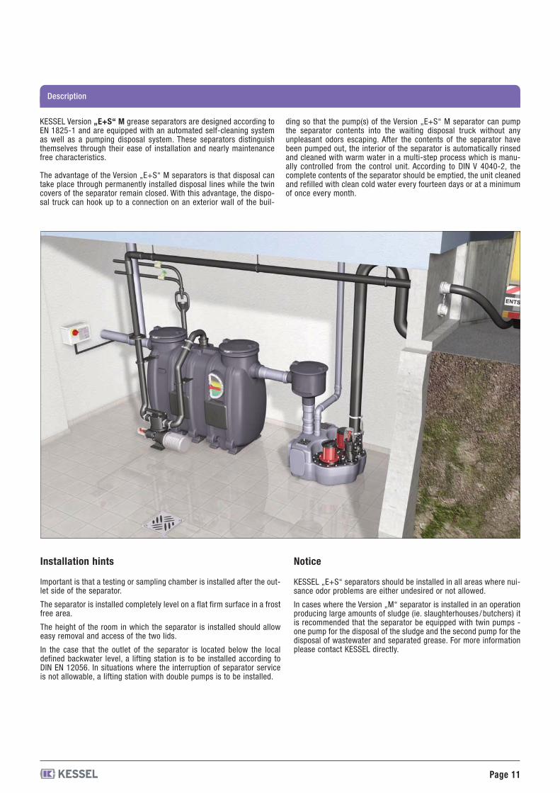
Important is that a testing or sampling chamber is installed after the out-let side of the separator.
The separator is installed completely level on a flat firm surface in a frostfree area.
The height of the room in which the separator is installed should alloweasy removal and access of the two lids.
In the case that the outlet of the separator is located below the localdefined backwater level, a lifting station is to be installed according toDIN EN 12056. In situations where the interruption of separator serviceis not allowable, a lifting station with double pumps is to be installed.
KESSEL „E+S“ separators should be installed in all areas where nui-sance odor problems are either undesired or not allowed.
In cases where the Version „M“ separator is installed in an operationproducing large amounts of sludge (ie. slaughterhouses /butchers) itis recommended that the separator be equipped with twin pumps -one pump for the disposal of the sludge and the second pump for thedisposal of wastewater and separated grease. For more informationplease contact KESSEL directly.
KESSEL Version „E+S“ M grease separators are designed according toEN 1825-1 and are equipped with an automated self-cleaning systemas well as a pumping disposal system. These separators distinguishthemselves through their ease of installation and nearly maintenancefree characteristics.
The advantage of the Version „E+S“ M separators is that disposal cantake place through permanently installed disposal lines while the twincovers of the separator remain closed. With this advantage, the dispo-sal truck can hook up to a connection on an exterior wall of the buil-
ding so that the pump(s) of the Version „E+S“ M separator can pumpthe separator contents into the waiting disposal truck without anyunpleasant odors escaping. After the contents of the separator havebeen pumped out, the interior of the separator is automatically rinsedand cleaned with warm water in a multi-step process which is manu-ally controlled from the control unit. According to DIN V 4040-2, thecomplete contents of the separator should be emptied, the unit cleanedand refilled with clean cold water every fourteen days or at a minimumof once every month.
Installation hints Notice
Description
Page 12
Art. # 93 004.00 / DS-P1Version flow direction right/ inspection window as accessory
Dimensioned illustration
Nominal size* Article #
NS 2NS 4NS 7NS 10
140 kg155 kg190 kg215 kg
for free standing installationin frost free areas
Installation site
93 002.50/DS-P193 004.50/DS-P193 007.50/DS-P193 010.50/DS-P1
93 002.00/DS-P193 004.00/DS-P193 007.00/DS-P193 010.00/DS-P1
left rightDisposal pipe connection
Scope of delivery
Container with 2 domedcovers, internal and externalpiping complete with disposalpipe connection, Shredder-Mix-System with on/offswitch, inlet
Ø
110110160160
a
1030150016002430
b
670730990990
b1
1000100012201220
h1
930930
11301130
h2
1000100012001200
h3
1310131015601560
Sludge trap
200 l400 l700 l
1000 l
Wastewater contentSeparator
212 l354 l567 l794 l
Greaseseparator
106 l177 l302 l423 l
Nominal size
NS 2**NS 4NS 7NS 10
Access openingl
1250181018502700
x
Ø = Outer diameter b1 = Installation dimensions
� �
bb1
�420l
a
h2 h1h3
�
�
** Please note: In the case of NS 2 the disposal pipe must be attached to the side opposite the pump.
Weight approx.
Grease separator Euro “D+S-P1” NS ...with direct disposal andprogramm controlled Shredder-Mix-Systemaccording to EN 1825,made of polymerFor free standing installation in frost free areas, withintegrated sludge trap, domed covers made of polymer,with snap closures and sealed odour-tight, with refill inletleft/right options available (with the exception of NS 2) 1 inch,with installed suction system for disposal both from the sludgetrap and the grease separating chamber, with flange connec-tion for intake pipe, disposal flange Ø 65, PN 10 accordingto DIN 2501, Storz-B-Coupling 21/2 inch for disposal truckconnection, with high pressure cleaning system.The Shredder-Mix-System serves to simultaneously macera-te and recycle the sediment and to clean the container.Separator requires disposal vehicle for emptying.Inlet and outlet Ø ... for synthetic material pipes in:PE-HD (according to DIN 19537); PP, AS or HT accordingto DIN 19560.Sludge trap content: ...... Liter Manufacturer: KESSELSeparator content: ...... Liter Article #: .......................Weight: ...... kg Certification no. Z-54.1-474Delivery: System completely assembled.
On-site welding available on request.
Article descriptionIllustration
Grease separator Euro “D+S-P1” according to EN 1825NS 2/4/7/10 with direct disposal and programm controlled Shredder-Mix-Systemfor free standing installation in frost free areas
* other sizes and custom-made separatorsavailable on request
Page 13
Description
Installation hints
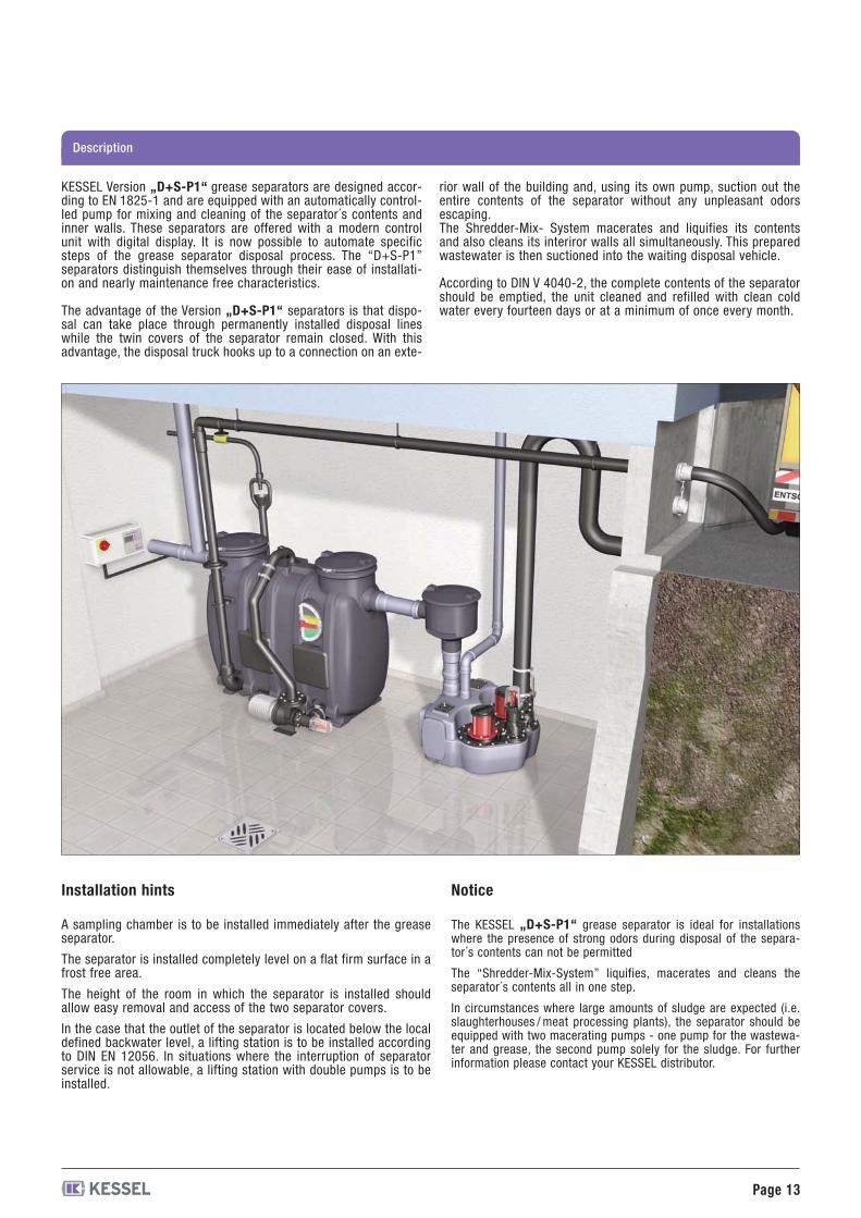
A sampling chamber is to be installed immediately after the greaseseparator.
The separator is installed completely level on a flat firm surface in afrost free area.
The height of the room in which the separator is installed shouldallow easy removal and access of the two separator covers.
In the case that the outlet of the separator is located below the localdefined backwater level, a lifting station is to be installed accordingto DIN EN 12056. In situations where the interruption of separatorservice is not allowable, a lifting station with double pumps is to beinstalled.
Notice
The KESSEL „D+S-P1“ grease separator is ideal for installationswhere the presence of strong odors during disposal of the separa-tor´s contents can not be permitted
The “Shredder-Mix-System” liquifies, macerates and cleans theseparator´s contents all in one step.
In circumstances where large amounts of sludge are expected (i.e.slaughterhouses / meat processing plants), the separator should beequipped with two macerating pumps - one pump for the wastewa-ter and grease, the second pump solely for the sludge. For furtherinformation please contact your KESSEL distributor.
KESSEL Version „D+S-P1“ grease separators are designed accor-ding to EN 1825-1 and are equipped with an automatically control-led pump for mixing and cleaning of the separator´s contents andinner walls. These separators are offered with a modern controlunit with digital display. It is now possible to automate specificsteps of the grease separator disposal process. The “D+S-P1”separators distinguish themselves through their ease of installati-on and nearly maintenance free characteristics.
The advantage of the Version „D+S-P1“ separators is that dispo-sal can take place through permanently installed disposal lineswhile the twin covers of the separator remain closed. With thisadvantage, the disposal truck hooks up to a connection on an exte-
rior wall of the building and, using its own pump, suction out theentire contents of the separator without any unpleasant odorsescaping.The Shredder-Mix- System macerates and liquifies its contentsand also cleans its interiror walls all simultaneously. This preparedwastewater is then suctioned into the waiting disposal vehicle.
According to DIN V 4040-2, the complete contents of the separatorshould be emptied, the unit cleaned and refilled with clean coldwater every fourteen days or at a minimum of once every month.
Page 14
Article descriptionIllustration
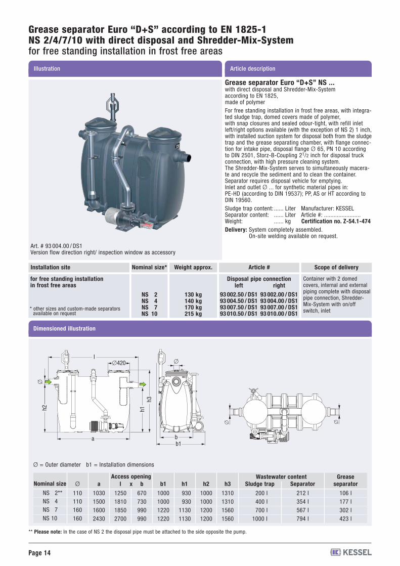
Grease separator Euro “D+S” according to EN 1825-1NS 2/4/7/10 with direct disposal and Shredder-Mix-Systemfor free standing installation in frost free areas
Art. # 93 004.00 / DS1Version flow direction right/ inspection window as accessory
Dimensioned illustration
Nominal size* Article #
NS 2NS 4NS 7NS 10
130 kg140 kg170 kg215 kg
for free standing installationin frost free areas
Installation site
93 002.50 / DS193 004.50 / DS193 007.50 / DS193 010.50 / DS1
93 002.00 / DS193 004.00 / DS193 007.00 / DS193 010.00 / DS1
left rightDisposal pipe connection
Scope of delivery
Container with 2 domedcovers, internal and externalpiping complete with disposalpipe connection, Shredder-Mix-System with on/offswitch, inlet
Ø
110110160160
a
1030150016002430
b
670730990990
b1
1000100012201220
h1
930930
11301130
h2
1000100012001200
h3
1310131015601560
Sludge trap
200 l400 l700 l
1000 l
Wastewater contentSeparator
212 l354 l567 l794 l
Greaseseparator
106 l177 l302 l423 l
Nominal size
NS 2**NS 4NS 7NS 10
Access openingl
1250181018502700
x
Ø = Outer diameter b1 = Installation dimensions
� �
bb1
�420l
a
h2 h1h3
�
�
** Please note: In the case of NS 2 the disposal pipe must be attached to the side opposite the pump.
Weight approx.
Grease separator Euro “D+S” NS ...with direct disposal and Shredder-Mix-Systemaccording to EN 1825,made of polymerFor free standing installation in frost free areas, with integra-ted sludge trap, domed covers made of polymer,with snap closures and sealed odour-tight, with refill inletleft/right options available (with the exception of NS 2) 1 inch,with installed suction system for disposal both from the sludgetrap and the grease separating chamber, with flange connec-tion for intake pipe, disposal flange Ø 65, PN 10 accordingto DIN 2501, Storz-B-Coupling 21/2 inch for disposal truckconnection, with high pressure cleaning system.The Shredder-Mix-System serves to simultaneously macera-te and recycle the sediment and to clean the container.Separator requires disposal vehicle for emptying.Inlet and outlet Ø ... for synthetic material pipes in:PE-HD (according to DIN 19537); PP, AS or HT according toDIN 19560.Sludge trap content: ...... Liter Manufacturer: KESSELSeparator content: ...... Liter Article #: .......................Weight: ...... kg Certification no. Z-54.1-474Delivery: System completely assembled.
On-site welding available on request.
* other sizes and custom-made separatorsavailable on request
Page 15
Description
Installation hints
A sampling chamber is to be installed immediately after the greaseseparator.
The separator is installed completely level on a flat firm surface in afrost free area.
The height of the room in which the separator is installed shouldallow easy removal and access of the two separator covers.
In the case that the outlet of the separator is located below the localdefined backwater level, a lifting station is to be installed accordingto DIN EN 12056. In situations where the interruption of separatorservice is not allowable, a lifting station with double pumps is to beinstalled.
Notice
The KESSEL “D+S” grease separator is ideal for installations wherethe presence of strong odors during disposal of the separator´s con-tents can not be permitted
The “Shredder-Mix-System” liquifies, macerates and cleans theseparator´s contents all in one step.
In circumstances where large amounts of sludge are expected (i.e.slaughterhouses / meat processing plants), the separator should beequipped with two macerating pumps - one pump for the wastewa-ter and grease, the second pump solely for the sludge. For furtherinformation please contact your KESSEL distributor.
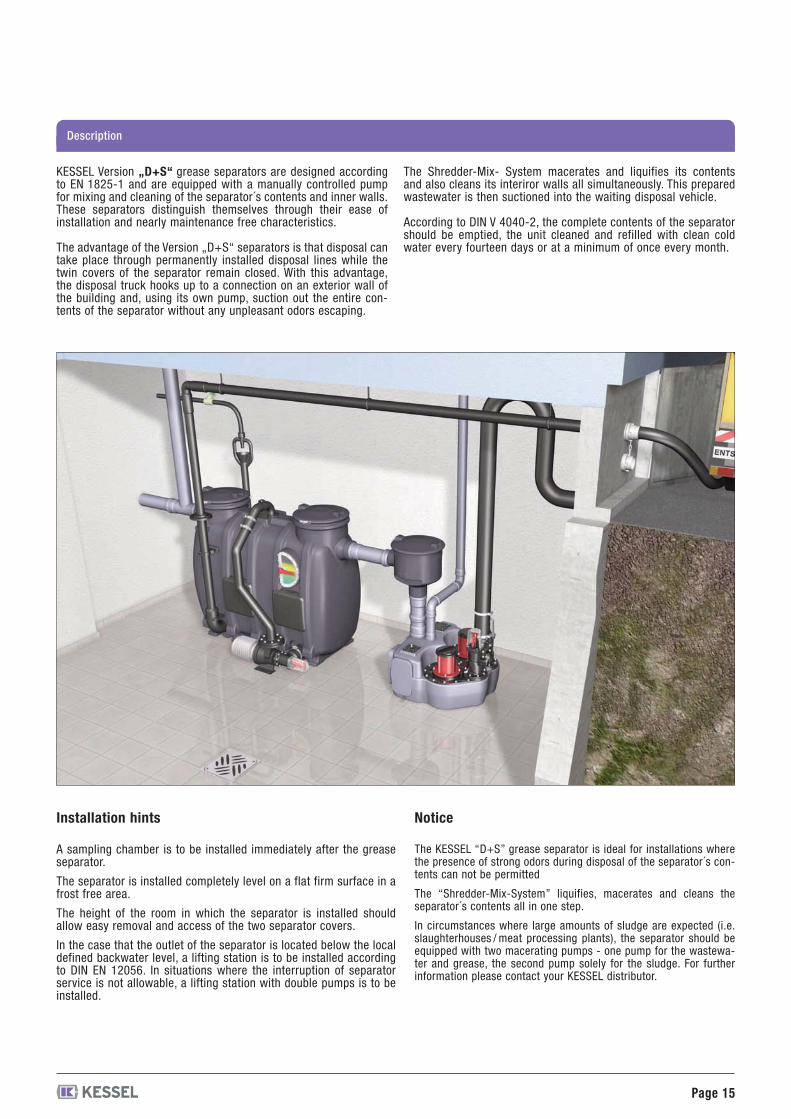
KESSEL Version „D+S“ grease separators are designed accordingto EN 1825-1 and are equipped with a manually controlled pumpfor mixing and cleaning of the separator´s contents and inner walls.These separators distinguish themselves through their ease ofinstallation and nearly maintenance free characteristics.
The advantage of the Version „D+S“ separators is that disposal cantake place through permanently installed disposal lines while thetwin covers of the separator remain closed. With this advantage,the disposal truck hooks up to a connection on an exterior wall ofthe building and, using its own pump, suction out the entire con-tents of the separator without any unpleasant odors escaping.
The Shredder-Mix- System macerates and liquifies its contentsand also cleans its interiror walls all simultaneously. This preparedwastewater is then suctioned into the waiting disposal vehicle.
According to DIN V 4040-2, the complete contents of the separatorshould be emptied, the unit cleaned and refilled with clean coldwater every fourteen days or at a minimum of once every month.
Page 16
Article descriptionIllustration
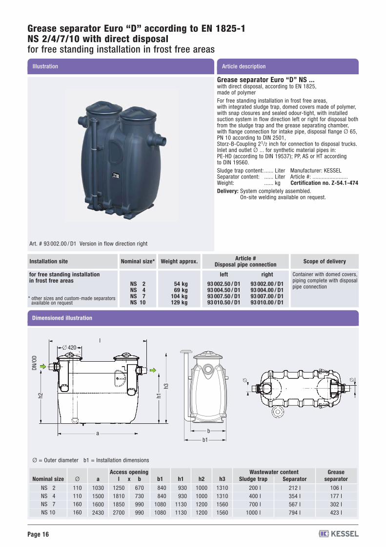
Grease separator Euro “D” according to EN 1825-1NS 2/4/7/10 with direct disposalfor free standing installation in frost free areas
Art. # 93 002.00 / D1 Version in flow direction right
Nominal size* Article #Disposal pipe connection
NS 2NS 4NS 7NS 10
54 kg69 kg
104 kg129 kg
for free standing installationin frost free areas
Dimensioned illustration
Installation site
b
b1
� �
Ø
110110160160
a
1030150016002430
b
670730990990
b1
840840
10801080
h1
930930
11301130
h2
1000100012001200
h3
1310131015601560
l
1250181018502700
Sludge trap
200 l400 l700 l
1000 l
Wastewater contentSeparator
212 l354 l567 l794 l
Greaseseparator
106 l177 l302 l423 l
Nominal size
NS 2NS 4NS 7NS 10
93 002.00 / D193 004.00 / D193 007.00 / D193 010.00 / D1
93 002.50 / D193 004.50 / D193 007.50 / D193 010.50 / D1
rightleft
Scope of delivery
Container with domed covers,piping complete with disposalpipe connection
Ø = Outer diameter b1 = Installation dimensions
420
h2 h1h3
l
a
DN/OD
xAccess opening
Grease separator Euro “D” NS ...with direct disposal, according to EN 1825,made of polymerFor free standing installation in frost free areas,with integrated sludge trap, domed covers made of polymer,with snap closures and sealed odour-tight, with installedsuction system in flow direction left or right for disposal bothfrom the sludge trap and the grease separating chamber,with flange connection for intake pipe, disposal flange Ø 65,PN 10 according to DIN 2501,Storz-B-Coupling 21/2 inch for connection to disposal trucks.Inlet and outlet Ø ... for synthetic material pipes in:PE-HD (according to DIN 19537); PP, AS or HT accordingto DIN 19560.Sludge trap content: ...... Liter Manufacturer: KESSELSeparator content: ...... Liter Article #: .......................Weight: ...... kg Certification no. Z-54.1-474Delivery: System completely assembled.
On-site welding available on request.
Weight approx.
* other sizes and custom-made separatorsavailable on request
Page 17
Description
Installation hints
Important is that a testing or sampling chamber is installed after the out-let side of the separator.
The separator is installed completely level on a flat firm surface in a frostfree area.
The height of the room in which the separator is installed should alloweasy removal and access of the two lids.
In the case that the outlet of the separator is located below the localdefined backwater level, a lifting station is to be installed according toDIN 1986-7. In situations where the interruption of separator service isnot allowable, a lifting station with double pumps is to be installed.
Notice
The KESSEL Version „D“ separator should be inspected and fullycleaned during every third disposal.
In all circumstances where the accessibility of the disposal truck’ssuction hose to the separator is highly limited or impossible, KESSELrecommends the installation of a Version „D“ unit.
With the installation of the refill equipment, the KESSEL Version „D“separator can be refilled after disposal without the need of openingany of the covers and releasing strong and aggressive odors.
The KESSEL Version „D“ separator is not intended for use in meatprocessing plants.
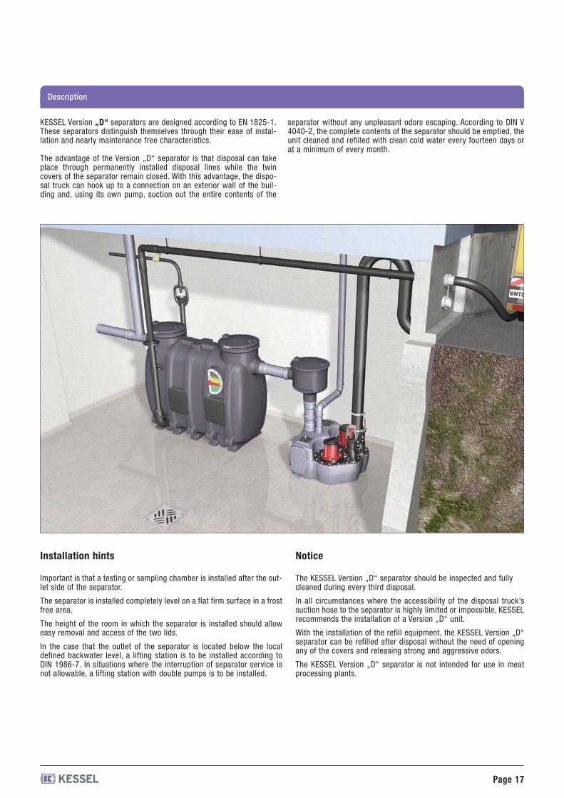
KESSEL Version „D“ separators are designed according to EN 1825-1.These separators distinguish themselves through their ease of instal-lation and nearly maintenance free characteristics.
The advantage of the Version „D“ separator is that disposal can takeplace through permanently installed disposal lines while the twincovers of the separator remain closed. With this advantage, the dispo-sal truck can hook up to a connection on an exterior wall of the buil-ding and, using its own pump, suction out the entire contents of the
separator without any unpleasant odors escaping. According to DIN V4040-2, the complete contents of the separator should be emptied, theunit cleaned and refilled with clean cold water every fourteen days orat a minimum of every month.
Page 18
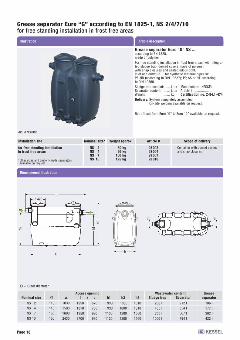
Article descriptionIllustration
Grease separator Euro “G” according to EN 1825-1, NS 2/4/7/10for free standing installation in frost free areas
Dimensioned illustration
Art. # 93 002
Nominal size* Scope of deliveryArticle #
NS 2NS 4NS 7NS 10
50 kg65 kg
100 kg125 kg
93 00293 00493 00793 010
for free standing installationin frost free areas
Container with domed coversand snap closures
Installation site
��
b
Ø
110110160160
a
1030150016002430
b
670730990990
h1
930930
11301130
h2
1000100012001200
h3
1310131015601560
l
1250181018502700
x Sludge trap
200 l400 l700 l
1000 l
Wastewater contentAccess openingSeparator
212 l354 l567 l794 l
Greaseseparator
106 l177 l302 l423 l
Nominal size
NS 2NS 4NS 7NS 10
Ø = Outer diameter
420
h1h3
h2
a
Weight approx.
Grease separator Euro “G” NS ...according to EN 1825,made of polymerFor free standing installation in frost free areas, with integra-ted sludge trap, domed covers made of polymer,with snap closures and sealed odour-tight.Inlet and outlet Ø ... for synthetic material pipes in:PE-HD (according to DIN 19537); PP, AS or HT accordingto DIN 19560.Sludge trap content: ...... Liter Manufacturer: KESSELSeparator content: ...... Liter Article #: ........................Weight: ...... kg Certification no. Z-54.1-474Delivery: System completely assembled.
On-site welding available on request.
Retrofit set from Euro “G” to Euro “D” available on request.
* other sizes and custom-made separatorsavailable on request
Page 19
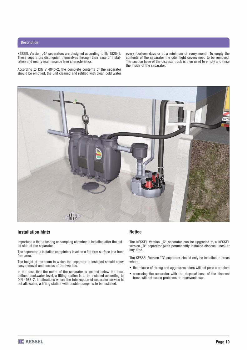
Description
KESSEL Version „G“ separators are designed according to EN 1825-1.These separators distinguish themselves through their ease of instal-lation and nearly maintenance free characteristics.
According to DIN V 4040-2, the complete contents of the separatorshould be emptied, the unit cleaned and refilled with clean cold water
every fourteen days or at a minimum of every month. To empty thecontents of the separator the odor tight covers need to be removed.The suction hose of the disposal truck is then used to empty and rinsethe inside of the separator.
Installation hints
Important is that a testing or sampling chamber is installed after the out-let side of the separator.
The separator is installed completely level on a flat firm surface in a frostfree area.
The height of the room in which the separator is installed should alloweasy removal and access of the two lids.
In the case that the outlet of the separator is located below the localdefined backwater level, a lifting station is to be installed according toDIN 1986-7. In situations where the interruption of separator service isnot allowable, a lifting station with double pumps is to be installed.
Notice
The KESSEL Version „G“ separator can be upgraded to a KESSELversion „D“ separator (with permanently installed disposal lines) atany time.
The KESSEL Version ”G” separator should only be installed in areaswhere:
• the release of strong and aggressive odors will not pose a problem
• accessing the separator with the disposal hose of the disposaltruck will not cause problems or inconveniences.
Page 20
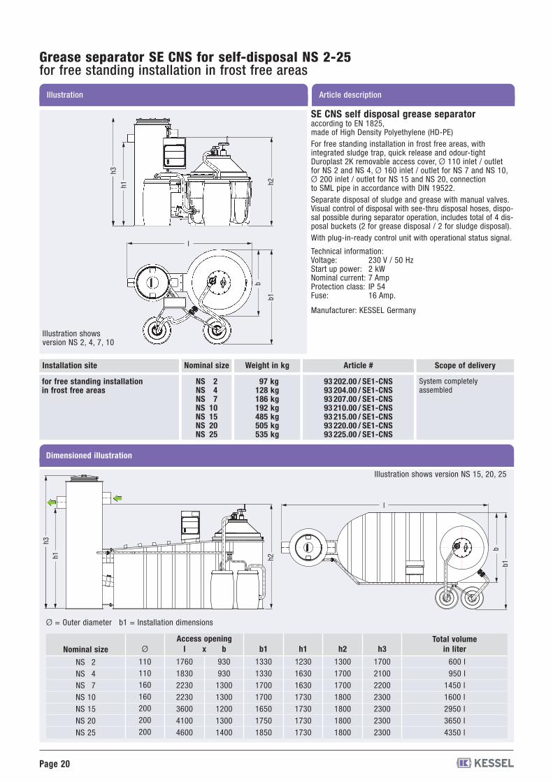
Grease separator SE CNS for self-disposal NS 2-25for free standing installation in frost free areas
Article descriptionIllustration
SE CNS self disposal grease separatoraccording to EN 1825,made of High Density Polyethylene (HD-PE)For free standing installation in frost free areas, withintegrated sludge trap, quick release and odour-tightDuroplast 2K removable access cover, Ø 110 inlet / outletfor NS 2 and NS 4, Ø 160 inlet / outlet for NS 7 and NS 10,Ø 200 inlet / outlet for NS 15 and NS 20, connectionto SML pipe in accordance with DIN 19522.Separate disposal of sludge and grease with manual valves.Visual control of disposal with see-thru disposal hoses, dispo-sal possible during separator operation, includes total of 4 dis-posal buckets (2 for grease disposal / 2 for sludge disposal).With plug-in-ready control unit with operational status signal.
Technical information:Voltage: 230 V / 50 HzStart up power: 2 kWNominal current: 7 AmpProtection class: IP 54Fuse: 16 Amp.
Manufacturer: KESSEL Germany
Dimensioned illustration
Nominal size Article #
NS 2NS 4NS 7NS 10NS 15NS 20NS 25
97 kg128 kg186 kg192 kg485 kg505 kg535 kg
93 202.00 / SE1-CNS93 204.00 / SE1-CNS93 207.00 / SE1-CNS93 210.00 / SE1-CNS93 215.00 / SE1-CNS93 220.00 / SE1-CNS93 225.00 / SE1-CNS
for free standing installationin frost free areas
Installation site Scope of delivery
System completelyassembled
Ø
110110160160200200200
b
93093013001300120013001400
b1
1330133017001700165017501850
h1
1230163016301730173017301730
h2
1300170017001800180018001800
h3
1700210022002300230023002300
in liter
600 l950 l
1450 l1600 l2950 l3650 l4350 l
Total volumeNominal size
NS 2NS 4NS 7NS 10NS 15NS 20NS 25
Access openingl
1760183022302230360041004600
x
Ø = Outer diameter b1 = Installation dimensions
Weight in kg
h2b1
b
h1h3
l
h2h1h3
b1b
l
Illustration showsversion NS 2, 4, 7, 10
Illustration shows version NS 15, 20, 25

Page 21
Grease separator “Under sink”for free standing installation in frost free areas
Article descriptionIllustration
Ø
50
Sludge trap
7 l
Grease trap
7 l
Nominal size
NS 0.25
Storage volumes
Nominal size (l/sec.) Article #
NS 0.25 4 kg 93 025.00 / USfor free standing installationin frost free areas
Installation site Weight approx.
Grease separator “Under sink”made of polymerFor free standing installation in frost free areas,with integrated sludge trap, polyethylene quick releaseodour-tight covers.Inlet and outlet Ø 50.Sludge trap content: 7 LiterGrease trap content:7 Liter
Manufacturer: KESSEL Germany
Application:Especially suitable in areas in which limited amountsof fat and sludge occur, and above all wherever vegetableoil is used.Grease separator system should be emptied on a daily basis.
KESSEL-advantages:- System made from polymer for corrosion-free,compact structure.
- No encrustation because of smooth, wax-like surface.- Light handling of system because of low weight.- Fast removal of cover using quick release odour tight covers.- Fully adjustable inlet: 360° rotatable and verticallyadjustable inlet meets all on-site requirements.
Dimensioned illustration
350
260
290to420 296
426
790 to 930
Ø50
Ø50
Page 22
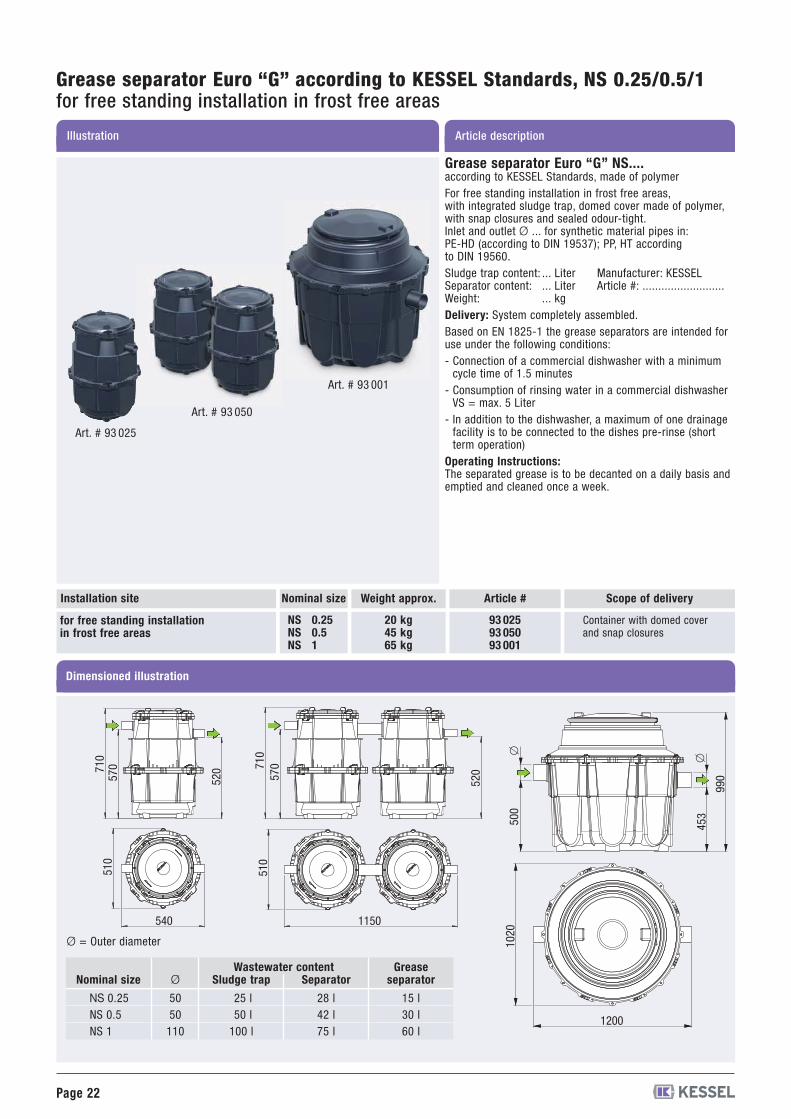
Article descriptionIllustration
Grease separator Euro “G” according to KESSEL Standards, NS 0.25/0.5/1for free standing installation in frost free areas
Grease separator Euro “G” NS....according to KESSEL Standards, made of polymerFor free standing installation in frost free areas,with integrated sludge trap, domed cover made of polymer,with snap closures and sealed odour-tight.Inlet and outlet Ø ... for synthetic material pipes in:PE-HD (according to DIN 19537); PP, HT accordingto DIN 19560.Sludge trap content: ... Liter Manufacturer: KESSELSeparator content: ... Liter Article #: ..........................Weight: ... kgDelivery: System completely assembled.Based on EN 1825-1 the grease separators are intended foruse under the following conditions:- Connection of a commercial dishwasher with a minimumcycle time of 1.5 minutes
- Consumption of rinsing water in a commercial dishwasherVS = max. 5 Liter
- In addition to the dishwasher, a maximum of one drainagefacility is to be connected to the dishes pre-rinse (shortterm operation)
Operating Instructions:The separated grease is to be decanted on a daily basis andemptied and cleaned once a week.
Art. # 93 025
Art. # 93 050
Art. # 93 001
Nominal size Scope of deliveryArticle #
NS 0.25NS 0.5NS 1
20 kg45 kg65 kg
93 02593 05093 001
for free standing installationin frost free areas
Container with domed coverand snap closures
Dimensioned illustration
Installation site
Ø
5050110
Sludge trap
25 l50 l100 l
Separator
28 l42 l75 l
Greaseseparator
15 l30 l60 l
Nominal size
NS 0.25NS 0.5NS 1
Ø = Outer diameter
710
570
520
510
540
710
570
520
510
1150
1200
1020
453500
990
�
�
Wastewater content
Weight approx.
Page 23
Article descriptionIllustration and dimensioned drawing
AccessoriesSeparator according to EN 1825 for free standing installation
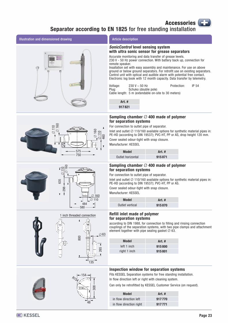
Refill inlet made of polymerfor separation systemsaccording to DIN 1988, for connection to filling and rinsing connectioncouplings of the separation systems, with two pipe clamps and attachmentelement together with pipe sealing gasket Ø 63.
Model
left 1 inchright 1 inch
Art. #
915 800915 801
135
63
800
265
Model
Outlet vertical
Art. #
915 870
Sampling chamber Ø 400 made of polymerfor separation systemsFor connection to outlet pipe of separator.Inlet and outlet Ø 110/160 available options for synthetic material pipes in:PE-HD (according to DIN 19537); PVC-HT, PP or AS.Cover sealed odour-tight with snap closure.Manufacturer: KESSEL
580484
� 160� 110
�110
�16
0
635
298
Sampling chamber Ø 400 made of polymerfor separation systemsFor connection to outlet pipe of separator.Inlet and outlet Ø 110/160 available options for synthetic material pipes in:PE-HD (according to DIN 19537); PVC-HT, PP or AS, drop height 120 mm.Cover sealed odour-tight with snap closure.Manufacturer: KESSEL
Model
Outlet horizontal
Art. #
915 871
575750
�110
�16
0
120
�110
�16
0
460
Inspection window for separation systemsFits KESSEL Separation systems for free standing installation.In flow direction left or right with cleaning system.
Can only be retrofitted by KESSEL Customer Service (on request).
Model
in flow direction left
in flow direction right
Art. #
917 770
917 771
154
48
308
R154
1 inch threaded connection
Art. #
917 821
SonicControl level sensing systemwith ultra sonic sensor for grease separatorsAccurate monitoring and data transfer of grease levels.230 V - 50 Hz power connection. With battery back up, connection forremote speaker.Insallation set with easy assembly and maintenance. For use on aboveground or below ground separators. For retrofit use on existing separators.Control unit with optical and audible alarm with potential free contact.Electronic log book with 12 month capacity. Data transfer by telemetry.
Voltage: 230 V ~ 50 Hz Protection: IP 54Plug: Schuko (double pole)Cable length: 5 m (extendable on-site to 30 meters)
Page 24
Article descriptionIllustration and dimensioned drawing
AccessoriesSeparator according to EN 1825 for free standing installation
Art. #
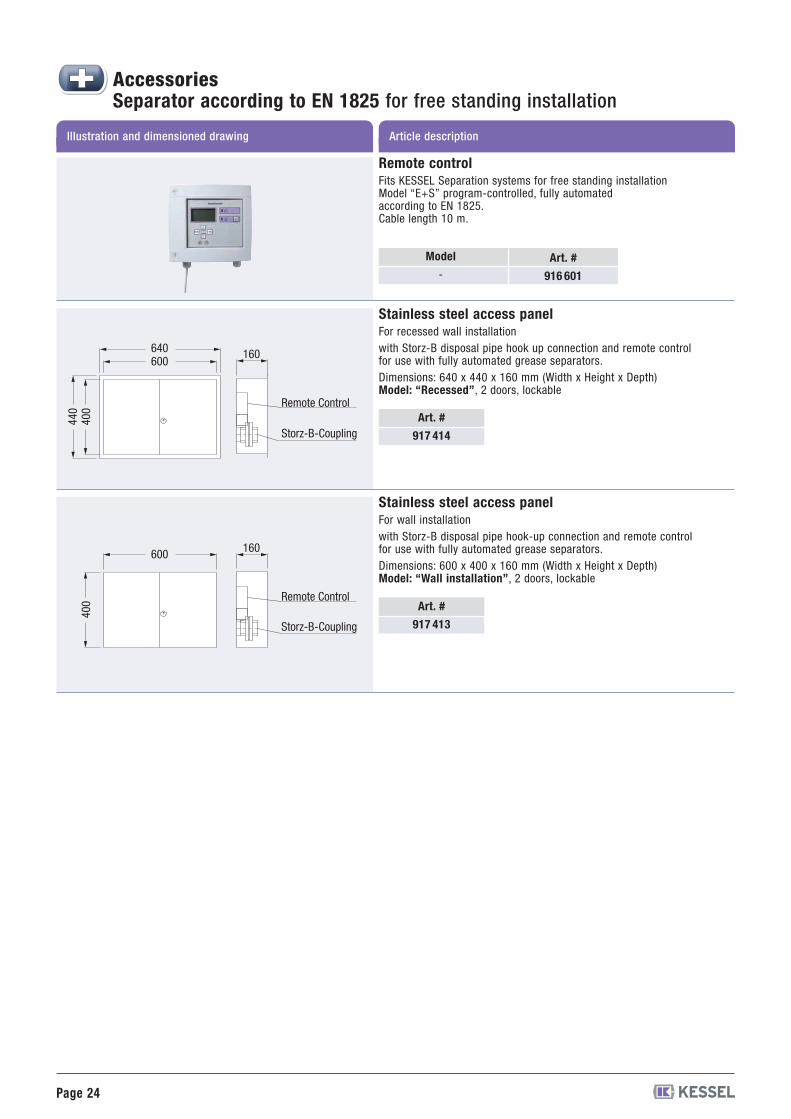
917 414
Art. #
917 413
Stainless steel access panelFor recessed wall installationwith Storz-B disposal pipe hook up connection and remote controlfor use with fully automated grease separators.Dimensions: 640 x 440 x 160 mm (Width x Height x Depth)Model: “Recessed”, 2 doors, lockable
Stainless steel access panelFor wall installationwith Storz-B disposal pipe hook-up connection and remote controlfor use with fully automated grease separators.Dimensions: 600 x 400 x 160 mm (Width x Height x Depth)Model: “Wall installation”, 2 doors, lockable
640600
440
400
160
Remote Control
Storz-B-Coupling
600
400
160
Remote Control
Storz-B-Coupling
Model
-Art. #
916 601
Remote controlFits KESSEL Separation systems for free standing installationModel “E+S” program-controlled, fully automatedaccording to EN 1825.Cable length 10 m.

Page 25
AccessoriesSeparator according to EN 1825 for free standing installation
Twin lifting stationmade of polymer for above ground installationWith twin removable pumps, integrated backwater flap,Pressure diaphragm control.Inlet Ø 110, ventilation connection Ø 75 (incl. pipesealing gasket), control with potential free contact.Pressure connection: 11/2 inch outer thread orpressure pipe Ø 40 mm for PVC glued connection.Inlet height: 530 mmTotal height: 720 mm, Ø 450 mmVoltage: 230 V ~ 50 HzMax. container size: 55 lmax. pumping height: 8 mIntake power: 2 x 0.5 kWPower cable: 5 mWeight: approx. 25 kg
Ø 40 28 541
guaranteed
with
testedqualit
y
Type-testedand monitored
LGA Certification: Z-53.3-310EN 12050-2500
Ø 110
530
Ø40
258
575 72
0
Ecolift ®wastewater lifting systemfor pipes with natural gradient to the sewerThe alternative to a classical lifting stationFor wastewater with or without sewage,for installation in an exposed wastewater pipeWith protective cover. With integrated pump and abackwater valve locked by a motor. During normalconditions, the pipe cross section is open, in the caseof backwater the valve is closed and locked completelyautomatically. During the backwater period, soiledwater is drained using a pump with chopping device,via a pressure pipe over the backwater level. Plug-incontrol and warning unit with display, self-diagnosissystem (SDS) and battery buffering for maximumsafety, with logbook (diary function) for reading outthe past operating states.
Power cable / cable length: 5 mMains voltage/frequency: 230 V AC / 50 HzProtective rating: IP 54 (switch unit)Protective rating: IP 68 (motor)
Ø 110 L: 642 mm H: 405 mmØ 125 L: 645 mm H: 405 mmØ 160 L: 656 mm H: 405 mmØ 200 L: 720 mm H: 405 mm
21 10021 12521 15021 200
Ø 110Ø 125Ø 160Ø 200
9
H
Ø
L
Ø 40
* Ø = Outer Diameter
Art. #Ø*Article descriptionIllustration and dimensioned drawing
Certification: Z-53.2-487

Page 26
AccessoriesSeparator according to EN 1825 for free standing installation
Article descriptionIllustration and dimensioned drawing
Lifting station Aqualift ® F DuoTwin stationfor wastewater with or without sewagefor separation systemsConsisting of:Polyethylene storage chamber, chamber volumeapprox. 120 liters, pumping volume approx. 50 liters,with air pressure level detector, clean-out opening.Connection for inlet Ø 110 (inlet height 300 mm) andventilation Ø 75, connection coupling for manualdiaphragm pump Ø 32.Twin wastewater pump with non-chokable impellerto pump wastewater with or without sewage (openchannel passage 40 mm). Pump is rated submersible(IP 68), power cable length 5 m.Horizontal outlet with integrated non-return valve,connection coupling Ø 110 with hose section,with closure valve (provided loose)Electric control unit for fully automated pumpoperation, control unit is splash proof (IP 65),wall mounted, voltage 400 V DS at 50 Hz.With potential-free contact.Total weight approx. 84 kg.
1.1 kW2.2 kW
400 V400 V
28 65928 631
With closure valvewith horizontal pressure outlet:
773
780
160
788
590
�32
�110�75
�
Inleth
eight
300
EN 12050-1
Art. #Power Currentconnection
Lifting station Aqualift ® F Duo XXLtwin lifting station with closure valvefor wastewater with or without sewage(For use with grease separators size NS 10 and larger)for free standing installation in frost free areasConsists of:Polyethylene collection chambers,storage volume 750 liter, pumping volume 300 liter,pneumatic level control, twin 420 mm OD access /maintenance covers, Ø 160 inlet (Ø 200 availableupon request), inlet height 1055 mm, ventilation con-nection size Ø 110.Twin wastewater pumps with macerating (cuttingassembly) for pumping wastewater with or withoutraw sewage, IP 68 submersible pumps, Duty / Standbyoperation, 5 meter power cable length.Vertical pressure outlet with Ø 110 connection andflange, with closure valve and integrated backflowpreventer.Electrical control for fully automated pump control,IP 54 splash proof control unit housing, for wallmounting, operational voltage - 400 V DS,with potential free contact (BMS) connections).Total weight empty: approx 220 kg
EN 12050-118372000
1385
1296
985
1055
2.6 kW3.5 kW4.8 kW
400 V400 V400 V
28 63828 63928 640
* Ø = Outer Diameter
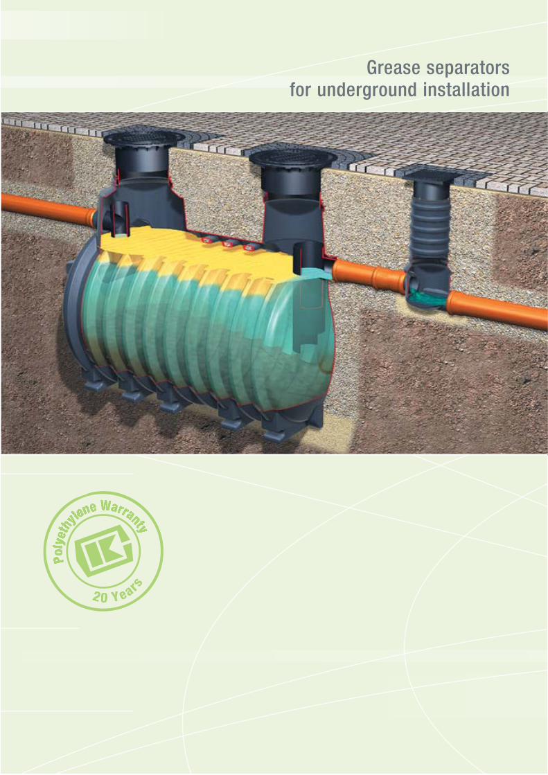
Grease separatorsfor underground installation
PPoollyy
eetthhyy
lleennee WWaaW rrrraannttyytt
20 Years

Page 28
Illustration
Variable upper section:inclinableheight adjustableby 100 to 550 mm
Article description
Grease separator Euro “G”according EN 1825-1, NS 1/2/4for underground installation
Grease separator Euro “G” NS ...according to EN 1825, made of polymerfor underground installation,installation depth D = ..................... mm,with integrated sludge trap, upper section made of polymer,continuous height and level adjustment, can be tilted upto 5°, sealed odour-tight with cover Class B, D accordingto EN 124 in cast iron, incl. removal mechanism, certified sta-tics.Inlet and outlet Ø 110 for synthetic material pipes in:PE-HD (according to DIN 19537); PVC (according toDIN V19534); PP or AS.Sludge trap content:...... Liter Manufacturer: KESSELSeparator content: ...... Liter Article #: .........................Weight: ...... kg Certification no. Z-54.1-440Delivery: System completely assembled.
Handles groundwater depths up to 500 mm
Nominal size Installation depth D
NS 1NS 2NS 4
111 kg120 kg130 kg
550 to 950 mm550 to 950 mm550 to 950 mm
for underground installationfrost free depth 800 mm(Type 80)
Dimensioned illustration
Installation site Art. # Class B Art. # Class D
93 001/80 B93 002/80 B93 004/80 B
93 001/80 D93 002/80 D93 004/80 D
NS 1NS 2NS 4
111 kg120 kg130 kg
800 to 1200 mm800 to 1200 mm800 to 1200 mm
for underground installationfrost free depth 1200 mm(Type 120)
93 001/120 B93 002/120 B93 004/120 B
93 001/120 D93 002/120 D93 004/120 D
Nominal size
NS 1NS 2NS 4
Ø
110110110
a
138013801380
b
110611061106
h*
105013001550
h1
540790
1040
h2
610860
1110
Sludge trap
140 l200 l400 l
Wastewater contentSeparator
230 l370 l370 l
Greaseseparator
70 l120 l160 l
b
a
� 875
h
� 610
�
h2 h1
�
D = Installation depth Ø = Outer diameter
Other installation depths available on request
* Details apply for Type 80. For Type 120 h* = h + 250 mm applies.
Art. # 93004/120D + 915880D
Inlet
D
Outlet
Weight approx.
Page 29
Description
Installation hints
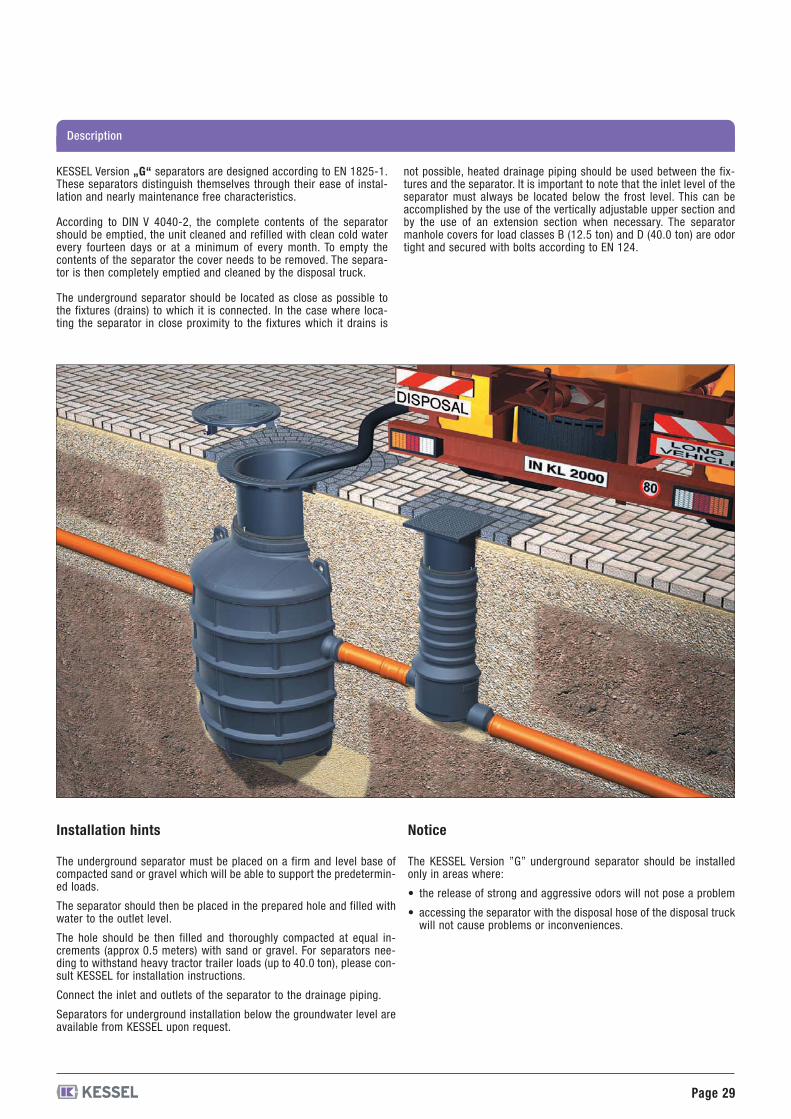
The underground separator must be placed on a firm and level base ofcompacted sand or gravel which will be able to support the predetermin-ed loads.
The separator should then be placed in the prepared hole and filled withwater to the outlet level.
The hole should be then filled and thoroughly compacted at equal in-crements (approx 0.5 meters) with sand or gravel. For separators nee-ding to withstand heavy tractor trailer loads (up to 40.0 ton), please con-sult KESSEL for installation instructions.
Connect the inlet and outlets of the separator to the drainage piping.
Separators for underground installation below the groundwater level areavailable from KESSEL upon request.
Notice
The KESSEL Version ”G” underground separator should be installedonly in areas where:
• the release of strong and aggressive odors will not pose a problem
• accessing the separator with the disposal hose of the disposal truckwill not cause problems or inconveniences.
KESSEL Version „G“ separators are designed according to EN 1825-1.These separators distinguish themselves through their ease of instal-lation and nearly maintenance free characteristics.
According to DIN V 4040-2, the complete contents of the separatorshould be emptied, the unit cleaned and refilled with clean cold waterevery fourteen days or at a minimum of every month. To empty thecontents of the separator the cover needs to be removed. The separa-tor is then completely emptied and cleaned by the disposal truck.
The underground separator should be located as close as possible tothe fixtures (drains) to which it is connected. In the case where loca-ting the separator in close proximity to the fixtures which it drains is
not possible, heated drainage piping should be used between the fix-tures and the separator. It is important to note that the inlet level of theseparator must always be located below the frost level. This can beaccomplished by the use of the vertically adjustable upper section andby the use of an extension section when necessary. The separatormanhole covers for load classes B (12.5 ton) and D (40.0 ton) are odortight and secured with bolts according to EN 124.
Page 30
Illustration
Variable upper section:inclinableheight adjustableby 100 to 550 mm
Article description
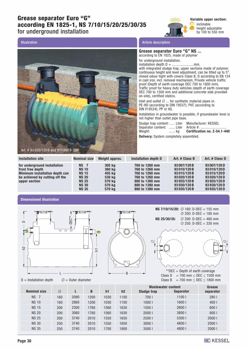
Grease separator Euro “G”according EN 1825-1, NS 7/10/15/20/25/30/35for underground installation
Nominal size Installation depth D
Art. # 93 020/120 B and 915 880 B-200
NS 7NS 10NS 15NS 20NS 25NS 30NS 35
305 kg360 kg455 kg530 kg570 kg570 kg570 kg
760 to 1260 mm760 to 1260 mm760 to 1260 mm760 to 1260 mm880 to 1380 mm880 to 1380 mm880 to 1380 mm
for underground installationfrost free depthMinimum installation depth canbe achieved by cutting off theupper section
BL
h1h2
� �
Dimensioned illustration
Installation site Art. # Class B Art. # Class D
93 007/120 B93 010/120 B93 015/120 B93 020/120 B93 925/120 B93 930/120 B93 935/120 B
93 007/120 D93 010/120D93 015/120D93 020/120 D93 925/120 D93 930/120 D93 935/120 D
Nominal size
NS 7NS 10NS 15NS 20NS 25NS 30NS 35
Ø
160160200200200250250
L
2080286023003060374037403740
B
1200120017601760201020102010
h1
1030103015601560155015501700
h2
1100110016301630165016501800
Sludge trap
700 l1000 l1500 l2000 l2500 l3000 l3500 l
Wastewater contentSeparator
1100 l1600 l2800 l3800 l5300 l4800 l4800 l
Greaseseparator
280 l400 l600 l800 l
2000 l2000 l2000 l
D = Installation depth Ø = Outer diameter
**DEC = Depth of earth coverageClass D = 700 mm ≤ DEC ≤ 1500 mmClass B = 700 mm ≤ DEC ≤ 1800 mm
Ø 160: D-DEC = 155 mmØ 200: D-DEC = 180 mm
Ø 200: D-DEC = 480 mmØ 250: D-DEC = 330 mm
NS 7/10/15/20:
NS 25/30/35:
Grease separator Euro “G” NS ...according to EN 1825, made of polymerfor underground installation,installation depth D = ......................mm,with integrated sludge trap, upper sections made of polymer,continuous height and level adjustment, can be tilted up to 5°,closed odour-tight with covers Class B, D according to EN 124in cast iron, incl. removal mechanism, Private vehicle trafficproof (Depth of earth coverage DEC 700 to 1800 mm),Traffic proof for heavy duty vehicles (depth of earth coverageDEC 700 to 1500 mm and additional concrete slab providedon-site), certified statics.Inlet and outlet Ø ... for synthetic material pipes in:PE-HD (according to DIN 19537); PVC (according toDIN V19534); PP or AS.Installation in groundwater is possible, if groundwater level isnot higher than outlet pipe base.Sludge trap content:...... Liter Manufacturer: KESSELSeparator content: ...... Liter Article #: ..........................Weight: ...... kg Certification no. Z-54.1-440Delivery: System completely assembled.
D DEC**
Weight approx.
Page 31
Illustration
Variable upper section:inclinableheight adjustableby 100 to 550 mm
Article description
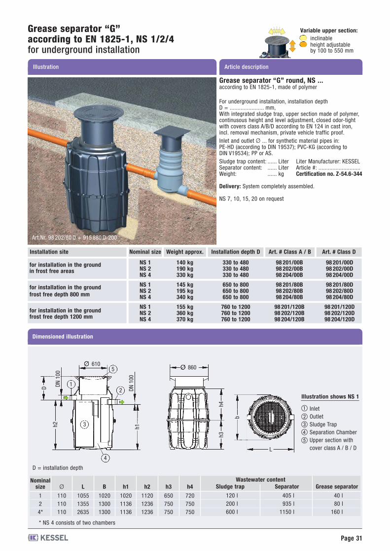
Grease separator “G”according to EN 1825-1, NS 1/2/4for underground installation
Grease separator “G” round, NS ...according to EN 1825-1, made of polymer
For underground installation, installation depthD = ...................... mm,With integrated sludge trap, upper section made of polymer,continusous height and level adjustment, closed odor-tightwith covers class A/B/D according to EN 124 in cast iron,incl. removal mechanism, private vehicle traffic proof.Inlet and outlet Ø ... for synthetic material pipes in:PE-HD (according to DIN 19537); PVC-KG (according toDIN V19534); PP or AS.Sludge trap content: ...... Liter Liter Manufacturer: KESSELSeparator content: ...... Liter Article #: ...........................Weight: ...... kg Certification no. Z-54.6-344
Delivery: System completely assembled.
NS 7, 10, 15, 20 on request
Nominal size Weight approx. Art. # Class A / B Art. # Class DInstallation depth D
NS 1NS 2NS 4
140 kg190 kg330 kg
98 201/00B98 202/00B98 204/00B
98 201/00D98 202/00D98 204/00D
330 to 480330 to 480330 to 480
for installation in the groundin frost free areas
for installation in the groundfrost free depth 800 mm
for installation in the groundfrost free depth 1200 mm
NS 1NS 2NS 4
145 kg195 kg340 kg
98 201/80B98 202/80B98 204/80B
98 201/80D98 202/80D98 204/80D
650 to 800650 to 800650 to 800
NS 1NS 2NS 4
155 kg360 kg370 kg
98 201/120B98 202/120B98 204/120B
98 201/120D98 202/120D98 204/120D
760 to 1200760 to 1200760 to 1200
Nominalsize
124*
Ø
110110110
L
105513552635
B
102013001300
h1
102011361136
h2
112012361236
h3
650750750
h4
720750750
Dimensioned illustration
610
DN100
DN100
h2 h1
4
3
21
5
D
860
h3h4
b
L
InletOutletSludge TrapSeparation ChamberUpper section withcover class A / B / D
Illustration shows NS 1
Installation site
D = installation depth
Sludge trap
120 l200 l600 l
Wastewater contentSeparator
405 l935 l
1150 l
Grease separator
40 l80 l
160 l
Art.Nr. 98 202/80 D + 915 880 D-200
* NS 4 consists of two chambers
Page 32
Article descriptionIllustration and dimensioned drawing
AccessoriesSeparator according to EN 1825 for underground installation
fits separatorNS 1, NS 2 and NS 4NS 7 and NS 10NS 15, NS 20 andcustom-made
Installationdepth D (mm)
1180-16301180-16301180-1630
OutletØ 110Ø 160Ø 200
Art. #Class DClass B
915 10 10 B915 10 15 B915 10 20 B
915 10 10 D915 10 15 D915 10 20 D
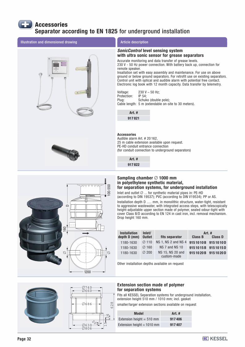
Sampling chamber Ø 1000 mmin polyethylene synthetic material,for separation systems, for underground installationInlet and outlet Ø ... for synthetic material pipes in: PE-HD(according to DIN 19537); PVC (according to DIN V19534); PP or AS.Installation depth D ..... mm, in monolithic structure, water-tight, resistantto aggressive wastewater, with integrated access steps, with telescopicallyheight-adjustable upper section made of polymer, sealed odour-tight withcover Class B/D according to EN 124 in cast iron, incl. removal mechanism.Drop height 160 mm.
160
� �
1200
100-550
Inlet/
Other installation depths available on request
Extension section made of polymerfor separation systemsFits all KESSEL Separation systems for underground installation,extension height 510 mm / 1010 mm; incl. gasket
smaller/larger extension sections available on request
Model
Extension height = 510 mm
Extension height = 1010 mm
Art. #
917 406
917 407
�660
�630�806
�686
�740
116
15
628
20°
D
Art. #
917 821
SonicControl level sensing systemwith ultra sonic sensor for grease separatorsAccurate monitoring and data transfer of grease levels.230 V - 50 Hz power connection. With battery back up, connection forremote speaker.Insallation set with easy assembly and maintenance. For use on aboveground or below ground separators. For retrofit use on existing separators.Control unit with optical and audible alarm with potential free contact.Electronic log book with 12 month capacity. Data transfer by telemetry.
Voltage: 230 V ~ 50 Hz;Protection: IP 54;Plug: Schuko (double pole);Cable length: 5 m (extendable on-site to 30 meters).
Art. #
917 822
AccessoriesAudible alarm Art. # 20 162,25 m cable extension available upon request.PE-HD conduit entrance connection(for conduit connection to underground separators)
Page 33
AccessoriesSeparator according to EN 1825 for underground installation
Article descriptionIllustration and dimensioned drawing
Installationdepth D (mm)
* 400-1300
* 400-1300
Inlet/outletØ
110/160200
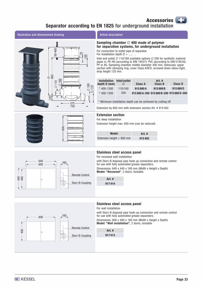
Sampling chamber Ø 400 made of polymerfor separation systems, for underground installationFor connection to outlet pipe of separator.For installation depth D = ...... .Inlet and outlet Ø 110/160 available options Ø 200 for synthetic materialpipes in: PE-HD (according to DIN 19537); PVC (according to DIN V19534);PP or AS. Sampling chamber middle diameter 400 mm, telescopic uppersection with clamping ring, cover Class A/B/D, screwed down odour-tight,drop height 120 mm.
Extension by 600 mm with extension section Art. # 915 402
575750
120
50-400
70
100
�160
�110
900
�110
�160 Art. #
Class D
915 880 D
915 880 D-200
Class B
915 880 B
915 880 B-200
Class A
915 880 A
915 880 A-200
* Minimum installation depth can be achieved by cutting off
Extension sectionFor deep installationExtension height max. 600 mm (can be reduced).
Model
Extension height = 600 mm
Art. #
915 402
600
D
Art. #
917 414
Art. #
917 413
Stainless steel access panelFor recessed wall installationwith Storz-B disposal pipe hook up connection and remote controlfor use with fully automated grease separators.Dimensions: 640 x 440 x 160 mm (Width x Height x Depth)Model: “Recessed”, 2 doors, lockable
Stainless steel access panelFor wall installationwith Storz-B disposal pipe hook-up connection and remote controlfor use with fully automated grease separators.Dimensions: 600 x 400 x 160 mm (Width x Height x Depth)Model: “Wall installation”, 2 doors, lockable
640600
440
400
160
Remote Control
Storz-B-Coupling
600
400
160
Remote Control
Storz-B-Coupling
Page 34
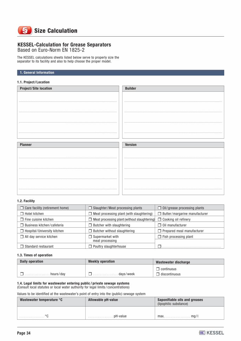
KESSEL-Calculation for Grease SeparatorsBased on Euro-Norm EN 1825-2The KESSEL calculations sheets listed below serve to properly size theseparator to its facility and also to help choose the proper model.
1. General Information
1.1. Project /Location
Project /Site location Builder
Planner Version
1.2. Facility
Care facility (retirement home)
Hotel kitchen
Fine cuisine kitchen
Business kitchen / cafeteria
Slaughter /Meat processing plants
Meat processing plant (with slaughtering)
Meat processing plant (without slaughtering)
Butcher with slaughtering
Oil / grease processing plants
Butter /margarine manufacturer
Cooking oil refinery
Oil manufacturer
Hospital /University kitchen Butcher without slaughtering Prepared meal manufacturer
All day service kitchen Supermarket withmeat processing
Fish processing plant
Standard restaurant Poultry slaughterhouse
1.3. Times of operation
Daily operation Weekly operation Wastewater discharge
. . . . . . . . . . . . . . . . . . . . . . . . hours / day . . . . . . . . . . . . . . . . . . . . . . . . days /weekcontinuousdiscontinuous
1.4. Legal limits for wastewater entering public / private sewage systems(Consult local statutes or local water authority for legal limits / concentrations)
Values to be identified at the wastewater’s point of entry into the (public) sewage system
Wastewater temperature °C Allowable pH-value Saponifiable oils and greases(lipophilic substance)
. . . . . . . . . . . . . . . . . . . . . . . . °C . . . . . . . . . . . . . . . . . . . . . . . . pH-value max. . . . . . . . . . . . . . . . . . . . . . . . . mg/ l
Size Calculation
Page 35
Size Calculation
Qs = . . . . . . . . . . . . . . . . . . . . . . . . . . . . . . . . . . . . . . . . . . . . . . . . . . . . . . . . . l / s
. . . . . . . . . . . . . . . . . . . . . . . . . l / s. . . . . . . . . . . . . . . . . . . . . . . . . Qs = . . . . . . . . . . . . . . . . . . . . . . . . . . . . . . . . . . . . . . . . . . . . . . . . . . . . . . . . . l / s
Qs = . . . . . . . . . . . . . . . . . . . . . . . . . . . . . . . . . . . . . . . . . . . . . . . . . . . . . . . . . l / s
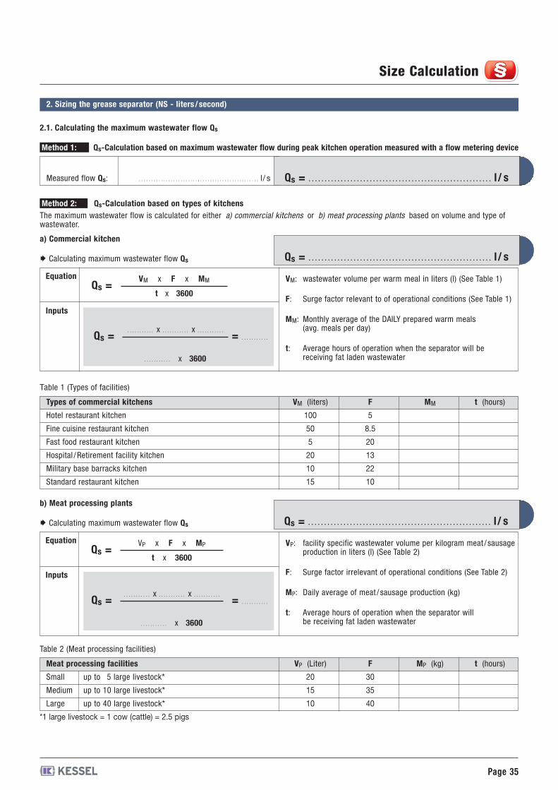
2. Sizing the grease separator (NS - liters /second)
2.1. Calculating the maximum wastewater flow Qs
Measured flow Qs:
Method 1: Qs-Calculation based on maximum wastewater flow during peak kitchen operation measured with a flow metering device
Method 2: Qs-Calculation based on types of kitchensThe maximum wastewater flow is calculated for either a) commercial kitchens or b) meat processing plants based on volume and type ofwastewater.
Table 1 (Types of facilities)
Types of commercial kitchens
Hotel restaurant kitchen
Fine cuisine restaurant kitchen
Fast food restaurant kitchen
Hospital /Retirement facility kitchen
Military base barracks kitchen
Standard restaurant kitchen
VM (liters)
100
50
5
20
10
15
F
5
8.5
20
13
22
10
MM t (hours)
a) Commercial kitchen
Equation
Inputs
Calculating maximum wastewater flow Qs
VM: wastewater volume per warm meal in liters (l) (See Table 1)
F: Surge factor relevant to of operational conditions (See Table 1)
MM: Monthly average of the DAILY prepared warm meals(avg. meals per day)
t: Average hours of operation when the separator will bereceiving fat laden wastewater
Qs =
Qs = = . . . . . . . . . . .
VM x F x MM
t x 3600
. . . . . . . . . . . x . . . . . . . . . . . x . . . . . . . . . . .
. . . . . . . . . . . x 3600
Qs =. . . . . . . . . . . x . . . . . . . . . . . x . . . . . . . . . . .
. . . . . . . . . . . x 3600
= . . . . . . . . . . .
b) Meat processing plants
Equation
Inputs
Calculating maximum wastewater flow Qs
VP: facility specific wastewater volume per kilogram meat / sausageproduction in liters (l) (See Table 2)
F: Surge factor irrelevant of operational conditions (See Table 2)
MP: Daily average of meat / sausage production (kg)
t: Average hours of operation when the separator willbe receiving fat laden wastewater
Qs =VP x F x MP
t x 3600
Table 2 (Meat processing facilities)
Meat processing facilities
Small
Medium
Large
*1 large livestock = 1 cow (cattle) = 2.5 pigs
up to 5 large livestock*
up to 10 large livestock*
up to 40 large livestock*
VP (Liter)
20
15
10
F
30
35
40
MP (kg) t (hours)
Page 36
Qs (K) = . . . . . . . . . . . . . . . . . . . . . . . . . . . . . . . . . . . . . . . . . . . . . . . . . . . . . . . l / s
Qs = . . . . . . . . . . . . . . . . . . . . . . . . . . . . . . . . . . . . . . . . . . . . . . . . . . . . . . . l / s
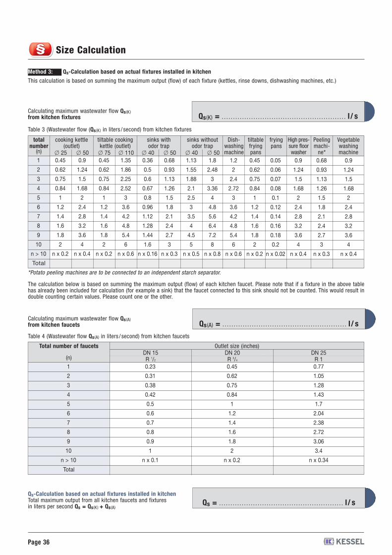
Method 3: Qs-Calculation based on actual fixtures installed in kitchen
This calculation is based on summing the maximum output (flow) of each fixture (kettles, rinse downs, dishwashing machines, etc.)
Calculating maximum wastewater flow Qs (K)from kitchen fixtures
Table 3 (Wastewater flow (Qs (K) in liters / second) from kitchen fixtures
Dish-washingmachine
tiltablefryingpans
fryingpans
High pres-sure floorwasher
Peelingmachi-ne*
Vegetablewashingmachine
cooking kettle(outlet)
totalnumber
1� 25 � 50
tiltable cookingkettle (outlet)
� 75 � 110
sinks withodor trap
� 40 � 50
sinks withoutodor trap
� 40 � 50
2
3
4
5
6
7
8
9
10
n > 10
0.45
0.62
0.75
0.84
1
1.2
1.4
1.6
1.8
2
n x 0.2
0.9
1.24
1.5
1.68
2
2.4
2.8
3.2
3.6
4
n x 0.4
0.45
0.62
0.75
0.84
1
1.2
1.4
1.6
1.8
2
n x 0.2
1.35
1.86
2.25
2.52
3
3.6
4.2
4.8
5.4
6
n x 0.6
0.36
0.5
0.6
0.67
0.8
0.96
1.12
1.28
1.44
1.6
n x 0.16
0.68
0.93
1.13
1.26
1.5
1.8
2.1
2.4
2.7
3
n x 0.3
1.13
1.55
1.88
2.1
2.5
3
3.5
4
4.5
5
n x 0.5
1.8
2.48
3
3.36
4
4.8
5.6
6.4
7.2
8
n x 0.8
1.2
2
2.4
2.72
3
3.6
4.2
4.8
5.4
6
n x 0.6
0.45
0.62
0.75
0.84
1
1.2
1.4
1.6
1.8
2
n x 0.2
0.05
0.06
0.07
0.08
0.1
0.12
0.14
0.16
0.18
0.2
n x 0.02
0.9
1.24
1.5
1.68
2
2.4
2.8
3.2
3.6
4
n x 0.4
0.68
0.93
1.13
1.26
1.5
1.8
2.1
2.4
2.7
3
n x 0.3
0.9
1.24
1.5
1.68
2
2.4
2.8
3.2
3.6
4
n x 0.4
Total
*Potato peeling machines are to be connected to an independent starch separator.
Qs (A) = . . . . . . . . . . . . . . . . . . . . . . . . . . . . . . . . . . . . . . . . . . . . . . . . . . . . . . . l / sCalculating maximum wastewater flow Qs (A)from kitchen faucets
Table 4 (Wastewater flow Qs (A) in liters / second) from kitchen faucets
Total number of faucets Outlet size (inches)
1
(n)
2
3
4
5
6
7
8
9
10
n > 10
0.23
0.31
0.38
0.42
0.5
0.6
0.7
0.8
0.9
1
n x 0.1
0.45
0.62
0.75
0.84
1
1.2
1.4
1.6
1.8
2
n x 0.2
0.77
1.05
1.28
1.43
1.7
2.04
2.38
2.72
3.06
3.4
n x 0.34
Total
DN 15R 1/2
DN 20R 3/4
DN 25R 1
Qs-Calculation based on actual fixtures installed in kitchenTotal maximum output from all kitchen faucets and fixturesin liters per second Qs = Qs (K) + Qs (A)
(n)
The calculation below is based on summing the maximum output (flow) of each kitchen faucet. Please note that if a fixture in the above tablehas already been included for calculation (for example a sink) that the faucet connected to this sink should not be counted. This would result indouble counting certain values. Please count one or the other.
Size Calculation
Page 37
Size Calculation
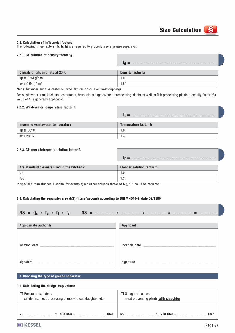
NS = Qs x fd x ft x fr NS = . . . . . . . . . . . . . . x . . . . . . . . . . . . . . x . . . . . . . . . . . . . . x . . . . . . . . . . . . . . = . . . . . . . . . . . . . .
fr = . . . . . . . . . . . . . . . . . . . . . . . . . . . . . . . . . . . . . . . . . . . . . . . . . . . . . . . . . . . . . .
ft = . . . . . . . . . . . . . . . . . . . . . . . . . . . . . . . . . . . . . . . . . . . . . . . . . . . . . . . . . . . . . .
fd = . . . . . . . . . . . . . . . . . . . . . . . . . . . . . . . . . . . . . . . . . . . . . . . . . . . . . . . . . . . . . .
*for substances such as castor oil, wool fat, resin / rosin oil, beef drippings.
For wastewater from kitchens, restaurants, hospitals, slaughter/meat proecessing plants as well as fish processing plants a density factor (fd)value of 1 is generally applicable.
2.2.1. Calculation of density factor fd
Density of oils and fats at 20°C
up to 0.94 g/cm3
over 0.94 g/cm3
Density factor fd1.0
1.5*
2.2.2. Wastewater temperature factor ft
Incoming wastewater temperature
up to 60°C
over 60°C
Temperature factor ft1.0
1.3
In special circumstances (Hospital for example) a cleaner solution factor of fr ≥ 1.5 could be required.
2.2.3. Cleaner (detergent) solution factor fr
Are standard cleaners used in the kitchen ?
No
Yes
Cleaner solution factor fr1.0
1.3
2.3. Calculating the separator size (NS) (liters /second) according to DIN V 4040-2, date 02/1999
Appropriate authority
location, date
signature
Applicant
location, date
signature
3. Choosing the type of grease separator
3.1. Calculating the sludge trap volume
Restaurants, hotels:cafeterias, meat processing plants without slaughter, etc.
NS . . . . . . . . . . . . . . . x 100 liter = . . . . . . . . . . . . . . . liter NS . . . . . . . . . . . . . . . x 200 liter = . . . . . . . . . . . . . . . liter
Slaughter houses:meat processing plants with slaughter
2.2. Calculation of influencial factorsThe following three factors ( fd, ft, fr) are required to properly size a grease separator.
Page 38
Grease separator /Accessories
L x W = . . . . . . . . . . . . . . . mm x . . . . . . . . . . . . . . . mm
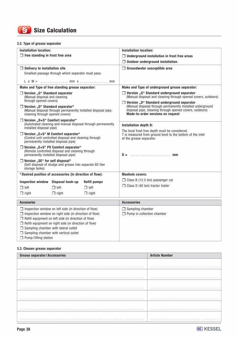
3.2. Type of grease separator
Installation location:free standing in frost free area
Installation location:
Underground installation in frost free areas
Outdoor underground installation.
Delivery to installation siteSmallest passage through which separator must pass:
Groundwater susceptible area
Make and Type of underground grease separator:
Version „G“ Standard underground separator(Manual disposal and cleaning through opened covers, outdoors)
Version „D“ Standard underground separator(Manual disposal through permanently installed undergrounddisposal pipe, cleaning through opened covers, outdoors)Made-to-order versions on request
* Desired position of accessories (in direction of flow):
Installation depth D:
The local frost free depth must be considered.T is measured from ground level to the bottom of the inletof the grease separator.
D = . . . . . . . . . . . . . . . . . . . . . . mm
Manhole covers:
Class B (12.5 ton) passenger car
Class D (40 ton) tractor trailer
Accessories
Inspection window on left side (in direction of flow)Inspection window on right side (in direction of flow)Refill equipment on left side (in direction of flow)Refill equipment on right side (in direction of flow)Sampling chamber with lateral outletSampling chamber with vertical outletPump / lifting station
Accessories
Sampling chamberPump in collection chamber
Article Number
. . . . . . . . . . . . . . . . . . . . . .. . . . . . . . . . . . . . . . . . . . . . . . . . . . . . . . . . . . . . . . . . . . .. . . . . . . . . . . . . . . . . . . . . . . . . . . . . . . . . . . . . . . . . . . . . . . . . . . . . . . . . . . . . . . . . . . . . . . . . . . . . . . . . . . . . . . . . . . . .. . . . . . . . . . . . . . . . . . . . . . . . . .
. . . . . . . . . . . . . . . . . . . . . . . . . . . . .. . . . . . . . . . . . . . . . . . . . . . . . . . . . . . . . . . . . . .. . . . . . . . . . . . . . . . . . . . . . . . . . . . . . . . . . . . . . . . . . . . . . . . . . . . . . . . . . . . . . . . . . . . . . . . . . . . . . . . . . . . . . . . . . . . .. . . . . . . . . . . . . . . . . . . . . . . . . .
. . . . . . . . . . . . . . . . . . . . . . . . . . .. . . . . . . . . . . . . . . . . . . . . . . . . . . . . . . . . . . . . . . .. . . . . . . . . . . . . . . . . . . . . . . . . . . . . . . . . . . . . . . . . . . . . . . . . . . . . . . . . . . . . . . . . . . . . . . . . . . . . . . . . . . . . . . . . . . . .. . . . . . . . . . . . . . . . . . . . . . . . . .
. . . . . . . . . . . . . . . . . . . . . . . . . . . . . . . . . . . . . . . . . . . . . . . . . . . .. . . . . . . . . . . . . . .. . . . . . . . . . . . . . . . . . . . . . . . . . . . . . . . . . . . . . . . . . . . . . . . . . . . . . . . . . . . . . . . . . . . . . . . . . . . . . . . . . . . . . . . . . . . .. . . . . . . . . . . . . . . . . . . . . . . . . .
. . . . . . . . . . . . . . . . . . . . . . . . . . . . . . . . . . . . . . . . . . . . . . . . . . . . . . . . . . . . . . . . . .. . . . . . . . . . . . . . . . . . . . . . . . . . . . . . . . . . . . . . . . . . . . . . . . . . . . . . . . . . . . . . . . . . . . . . . . . . . . . . . . . . . . . . . . . . . . .. . . . . . . . . . . . . . . . . . . . . . . . . .
3.3. Chosen grease separator
Inspection window
left
right
Disposal hook-up
left
right
Refill pumps
left
right
. . . . . . . . . . . . . . . . . . . . . . . . . . . . . . . . . . . . . . . . . . . . . . . . . . . . . . . . . . . . . . . . . .. . . . . . . . . . . . . . . . . . . . . . . . . . . . . . . . . . . . . . . . . . . . . . . . . . . . . . . . . . . . . . . . . . . . . . . . . . . . . . . . . . . . . . . . . . . . .. . . . . . . . . . . . . . . . . . . . . . . . . .
Make and Type of free standing grease separator:
Version „G“ Standard separator(Manual disposal and cleaningthrough opened covers)
Version „D“ Standard separator*(Manual disposal through permanently installed disposal pipe,cleaning through opened covers)
Version „D+S“ Comfort separator*(Automated cleaning and manual disposal through permanentlyinstalled disposal pipe)
Version „E+S“ M Comfort separator*(Control unit controlled disposal and cleaning throughpermanently installed disposal pipe)
Version „E+S“ PV Comfort separator*(Remote controlled disposal and cleaning throughpermanently installed disposal pipe)
Version „SE“ for self disposal*(Self disposal of sludge and grease into separate 60 literstorage tanks)
Size Calculation

Page 39
Notices
www.kessel.com
Leadingin
Drainage
Backwater Valves
Lifting Stations/Pumps
Drains
Separation Technology
Septic Systems
Polymer Chambers
Rainwater Management Systems
Quality for more safety, more success and satisfied customers
KESSEL AG · Bahnhofstr. 31 · 85101 Lenting · Germany
010-382 KA/CS 04/11
Righ
tsreserved
fortechnicalc
hang
es.