Embed Size (px)
Citation preview

EUROPEAN ORGANISATION FOR THE SAFETY OF AIR NAVIGATION
Enclosure 1
EUROCONTROL Specification for the Origination of Aeronautical Data
DOCUMENT IDENTIFIER: EUROCONTROL - SPEC - 0000
Edition Number : 0.2
Edition Date : 30/01/2012
Status : Draft
Intended for : General Public
Category : EUROCONTROL Specification
EUROCONTROL SPECIFICATION FOR THE ORIGINATION OF AERONAUTICAL DATA
Edition: 0.2 Draft Issue Page ii
DOCUMENT IDENTIFICATION SHEET
DOCUMENT DESCRIPTION
Document Title
EUROCONTROL Specification for the Origination of Aeronautical Data
Document Identifier Edition Number : 0.2
EUROCONTROL-SPEC-0000 Edition Date : 30/01/2012
Abstract
This EUROCONTROL Specification provides details of requirements which should be met by when originating aeronautical data in order to comply with the identified provisions of the Commission regulation (EU) 73/2010 laying down requirements on the quality of aeronautical data and aeronautical information for the single European sky.
Keywords
Contact Person: M. UNTERREINER Tel: +32 2 729 3038 Unit: SES
DOCUMENT STATUS AND TYPE
Status Intended for Category
Working Draft General Public EUROCONTROL Rule
Draft Restricted EUROCONTROL Specification
Proposed Issue EUROCONTROL EUROCONTROL Guideline
Released Issue
ELECTRONIC SOURCE
Path :
Host System Software Size
Microsoft Windows Microsoft Word 2007 Kb 2181

EUROCONTROL SPECIFICATION FOR THE ORIGINATION OF AERONAUTICAL DATA
DOCUMENT APPROVAL
The following table identifies all management authorities who have successively approved the present issue of this EUROCONTROL Specification.
AUTHORITY NAME AND SIGNATURE DATE
Roy Langridge / Kathryn Miles
Jürg Lüthy Editor Team
Jeremy Davidson
Task Manager DSR/CMN/NAV
Mr. Roland RAWLINGS
Director Single Sky
Mr. Luc TYTGAT
On behalf of the Director General by special delegation
Principal Director ATM
Mr. Bo REDEBORN
Edition: 0.2 Draft Issue Page iii

EUROCONTROL SPECIFICATION FOR THE ORIGINATION OF AERONAUTICAL DATA
DOCUMENT CHANGE RECORD
The following table records the complete history of the successive editions of the present document.
Edition Number
Edition Date
Reason for Change Pages
Affected
0.1 10/11/2011 Draft edition All
0.2 30/01/2012 Review and revisions to ensure ENPRM/ERAF consistency
All
Edition: 0.2 Draft Issue Page iv

EUROCONTROL SPECIFICATION FOR THE ORIGINATION OF AERONAUTICAL DATA
TABLE OF CONTENTS
DOCUMENT IDENTIFICATION SHEET.......................................................................................... ii
DOCUMENT APPROVAL............................................................................................................... iii
DOCUMENT CHANGE RECORD .................................................................................................. iv
TABLE OF CONTENTS...................................................................................................................v
Executive Summary ........................................................................................................................ vi
1 Introduction ..............................................................................................................................1
2 (Normative) Specification for Data Origination Requirements..................................................8
3 Testing and Verification..........................................................................................................46
4 Transition/Coexistence Issues ...............................................................................................47
5 Traceability to Regulatory Provisions.....................................................................................48
6 List of References ..................................................................................................................50
Annex A CONFIGURATION CONTROL ....................................................................................52
Annex B Conformity Material ......................................................................................................53
Annex C Traceability to Regulatory Provisions...........................................................................72
Annex D Guidance on the Application of Data Origination Requirements - Survey ...................75
Annex E Guidance on the Application of Data Origination Requirements – Procedure Design .76
Annex F Horizontal Reference Systems.....................................................................................77
Annex G Vertical Reference Systems.........................................................................................85
Annex H Monumentation ............................................................................................................89
Annex I Description of Airport Facilities.....................................................................................94
Annex J Description of Heliport Facilities.................................................................................114
Annex K Survey Procedures.....................................................................................................118
Annex L Computation and Derived Co-ordinates.....................................................................131
Annex M Specification Update Procedures...............................................................................132
Annex N Abbreviations .............................................................................................................134
Figure 1: Relationship of the EUROCONTROL Specification for the Origination of Aeronautical Data to Other Documents ................................................................................................................6
Figure 2: Geoid Undulations with Respect to an Ellipsoid .............................................................86
Table 1: Tolerance Values (Multipliers) for Aeronautical Data.......................................................20
Table 2: Geometric Constants .......................................................................................................78
Table 3: Some of WGS-84 Ellipsoid Derived Geometric Constants ..............................................78
Table 4: Continental Drift Expressed in Different ITRF Epochs .....................................................80
Edition: 0.2 Draft Issue Page v

EUROCONTROL SPECIFICATION FOR THE ORIGINATION OF AERONAUTICAL DATA
Executive Summary
This document is the European Organisation for the Safety of Air Navigation’s (EUROCONTROL) Specification for the Origination of Aeronautical Data.
This Specification has been designed to support Commission Regulation (EU) 73/2010, laying down requirements on the quality of aeronautical data and aeronautical information for the single European sky. This Specification concerns the origination of aeronautical data and, therefore, specifically supports Article 6(4), (5) and (6) of Commission Regulation (EU) 73/2010.
EUROCONTROL Specifications are used, most notably, as a possible Means of Compliance (MoC) to specific Single European Sky (SES) regulatory material. They are developed under full consideration of the Conformity Assessment (CA) Guidelines to support the achievement of the relevant provisions.
EUROCONTROL Specifications may be developed as stand-alone documents in support of EUROCONTROL Member States and stakeholders. They may also provide the basis of Community Specifications when subject to European Commission mandate.
This Specification will replace the EUROCONTROL Survey Standard 007-097 (Edition 1).
Edition: 0.2 Draft Issue Page vi
EUROCONTROL SPECIFICATION FOR THE ORIGINATION OF AERONAUTICAL DATA
Edition: 0.2 Draft Issue Page 1
1 Introduction
1.1 General
1.1.1 The European Organisation for the Safety of Air Navigation (EUROCONTROL) Specification for the Origination of Aeronautical Data has been developed, inter alia, to provide a means of compliance to the relevant parts of Commission Regulation (EU) No. 73/2010, of 26 January 2010, laying down requirements on the quality of aeronautical data and aeronautical information for the single European sky [Reference 1]1. It specifies how all functions that originate2 aeronautical data/information may meet the data quality requirements of Commission Regulation (EU) 73/2010.
1.1.2 The EUROCONTROL Regulatory and Advisory Framework (ERAF)3 has established the basis for the development of EUROCONTROL Specifications.
1.1.3 This Specification, once released, replaces the EUROCONTROL Survey Standard 007-097 (Edition 1). Note: The Specification would then also be proposed to ICAO as it may serve as input for an updated ICAO WGS-84 manual.
1.2 Background
1.2.1 Commission Regulation (EU) 73/2010 [Reference 1] has been introduced by the European Union (EU) as part of the Single European Sky (SES) initiative. Its intention is to improve the quality of aeronautical data/information made available by States, such that both current and future navigation are supported.
1.2.2 This need has primarily been driven by a long-standing acknowledgement that it was unlikely that the data quality requirements laid down by the International Civil Aviation Organisation (ICAO) were being met. In particular, this related to integrity, where the concept of the application of integrity to aeronautical data/information and, consequently, how to achieve it and to demonstrate compliance, were not well understood.
1.2.3 Commission Regulation (EU) 73/2010 [Reference 1] introduces high-level performance requirements, in the form of provisions, which place controls on the processes applied to aeronautical data/information, including the origination, handling and publication phases. Through this approach, the integrity of aeronautical data/information is assured by demonstrating that the processes applied give the required degree of assurance that the data will not be adversely affected.
1.2.4 Nonetheless, maintaining data with the required degree of integrity is only part of the solution. If data is not originated correctly, the resultant erroneous data will be processed with integrity. In essence, the system becomes one of “rubbish in, rubbish out”, with a high degree of assurance that the rubbish will not be altered.
1 References given in square brackets in this document refer to the list of documents in Chapter 6. 2 Origination is considered to be the act of creating a new value for a data item, amending the value of a data item or withdrawing a value associated with a data item. 3 EUROCONTROL Regulatory and Advisory Framework: http://www.eurocontrol.int/enprm/public/standard_page/enprm04002.html.

EUROCONTROL SPECIFICATION FOR THE ORIGINATION OF AERONAUTICAL DATA
1.2.5 To address this, Commission Regulation (EU) 73/2010 [Reference 1] includes provisions which are specifically intended to be met by those involved in the request for and origination of aeronautical data.
1.2.6 Commission Regulation (EU) 73/2010 [Reference 1] states that aeronautical data/information of appropriate quality is required to ensure safety and support new operational concepts throughout the European Air Traffic Management Network (EATMN). ICAO currently defines data quality requirements in terms of:
1) Accuracy;
2) Resolution;
3) Integrity.
1.2.7 Furthermore, in addition to the data quality requirements listed above, additional characteristics, such as completeness, consistency, timeliness and the need to determine the origin of data, are also addressed by Commission Regulation (EU) 73/2010 [Reference 1]. Consequently, these criteria must be met and maintained within the EATMN when originating and processing aeronautical data/information.
1.2.8 As data quality requirements are not defined for all of the data items and information within the Aeronautical Information Publication (AIP), the ICAO Standards and Recommended Practices (SARPs) are no longer considered to provide a sufficient baseline for data quality requirements. Consequently, Commission Regulation (EU) 73/2010 [Reference 1] includes provisions requiring the establishment of data quality requirements for all data items published within a State’s Integrated Aeronautical Information Package (IAIP) and for any electronic terrain and obstacle data and aerodrome mapping data that they may make available. This EUROCONTROL Specification assumes that these provisions have been met.
1.3 Scope
1.3.1 This EUROCONTROL Specification defines detailed requirements and recommendations, explanatory materials and conformity assessment materials providing a Means of Compliance (MoC) associated with Commission Regulation (EU) 73/2010 [Reference 1] Article 6(4), (5) and (6), insofar as the implementing rule requires that:
4) When acting as data originators, the parties referred to in Article 2(2), shall comply with the data origination requirements laid down in Annex IV, Part D.
5) Aeronautical information service providers shall ensure that aeronautical data and aeronautical information provided by data originators not referred to in Article 2(2) are made available to the next intended user with sufficient quality to meet the intended use.
6) When acting as the entity responsible for the official request for a data origination activity, the parties referred to in Article 2(2) shall ensure that:
a) the data are created, modified or deleted in compliance with their instructions;
b) without prejudice to Annex IV, Part C, their data origination instructions contain, as a minimum:
i) an unambiguous description of the data that are to be created, modified or deleted;
ii) confirmation of the entity to which the data are to be provided;
iii) the date and time by which the data are to be provided;
Edition: 0.2 Draft Issue Page 2

EUROCONTROL SPECIFICATION FOR THE ORIGINATION OF AERONAUTICAL DATA
Edition: 0.2 Draft Issue Page 3
iv) the data origination report format to be used by the data originator.
1.3.2 The scope of Commission Regulation (EU) 73/2010 [Reference 1] covers the IAIP (with the exception of the Aeronautical Information Circular), and, where made available by the State, electronic obstacle data, electronic terrain data and Aerodrome Mapping Data (AMD).
1.3.3 The requirements in this specification which must be met in order to be considered compliant with Article 6(4), (5) and (6) of Commission Regulation (EU) 73/2010 [Reference 1] are included in the normative Chapter 2. They comprise mandatory requirements4, as well as recommendations and optional requirements, the implementation of the latter two being optional. See section 1.4 for further details.
1.3.4 Data quality requirements for the data to be originated are not covered by this specification. However, these are included in other specifications supporting Commission Regulation (EU) 73/2010 [Reference 1]. See section 1.6 for further details.
1.3.5 This EUROCONTROL Specification also provides a list of the documents and standards which include additional requirements associated with the origination of data. Compliance with these requirements is necessary in order to achieve compliance with the specification and hence claim conformity with the identified provisions of Commission Regulation (EU) 73/2010 [Reference 1].
1.4 Conventions
1.4.1 A minimum subset of requirements necessary for the correct and harmonised origination of aeronautical data is specified. In addition, a number of recommendations are also made. Requirements (mandatory) within the EUROCONTROL Specification are clearly distinguished from recommendations / best practice, optional requirements and informative text.
1.4.2 This distinction is applied through the application of terminology. Conventions for denoting requirements, recommendations and optional requirements are as follows:
‘Shall’ - indicates a statement of specification, the compliance with which is mandatory to achieve the implementation of this EUROCONTROL Specification. It indicates a requirement which must be satisfied by all systems claiming conformity to this EUROCONTROL Specification5. Such requirements shall be testable and their implementation auditable.
‘Should’ - indicates a recommendation or best practice, which may or may not be satisfied by all systems claiming conformity to this Specification.
‘May’ – indicates an optional element.
1.4.3 In Annex B, the Implementation Conformance Statement (ICS) templates categorise the requirements, as follows:
“M” (Mandatory) for “shall” items;
“O” (Optional) for “should” or “may” items;
4 Whilst the adoption of this EUROCONTROL Specification is optional, the use of the phrase mandatory within it is used to indicate those requirements which must be met to claim conformity with the specification. 5 A demonstration of conformity with this EUROCONTROL Specification will bring about a presumption of conformity to the regulatory provisions for which the Specification has been formally recognised as a MoC.

EUROCONTROL SPECIFICATION FOR THE ORIGINATION OF AERONAUTICAL DATA
Edition: 0.2 Draft Issue Page 4
“CM” (Conditional and mandatory) items only apply when an optional parent requirement has been implemented. Conditional and mandatory items provide more detailed requirements about how the parent requirement is to be implemented;
“CO” (Conditional and optional) items only apply when an optional parent requirement has been implemented. Conditional and optional items provide more detailed optional elements about how the parent requirement may be implemented.
1.4.4 Every requirement and recommendation in this EUROCONTROL Specification is followed by a structured identifier, which can be used to uniquely reference the requirement/recommendation from associated documents and traceability tools. Such identifiers have the form:
DO-[Fn]-[nnnn]
where:
[Fn]: is a sequence of characters to identify the functional area to which the requirement applies, e.g. “FPD” for requirements related to instrument flight procedure design;
[nnnn]: is a numeric identifier for a sequence of requirements within the same functional area6.
1.4.5 Any text which does not contain one of the terms ‘shall’, ‘should’ or ‘may’ and which does not have a requirement number associated with it is provided as information only.
1.4.6 The functional areas referred to in paragraph 1.4.4 are:
DQR: Data Quality Requirements
REF: Reference System Specification;
n;
ftware;
nt Flight Procedure Design;
UOM: Units of Measurement;
DSS: Data Set Specifications;
DPS: Data Product Specificatio
CAT: Categories of Data;
PRO: Data Processing
EXC: Data Exchange;
QUA: Quality Assurance;
TSW: Tools and So
VAL: Validation and Verification;
SVY: Survey;
FPD: Instrume
ASD: Airspace Design.
6 Note that the requirement numbers are initially allocated incrementally in tens. This aids the subsequent management of this specification allowing new requirements to be inserted between existing requirements whilst maintaining a logical number sequence.

EUROCONTROL SPECIFICATION FOR THE ORIGINATION OF AERONAUTICAL DATA
Edition: 0.2 Draft Issue Page 5
1.5
1.5.1 ‘Main Body’, providing
detailed requirements for the MoC specified in this EUROCONTROL Specification, a number of Annexes providing supporting material and an Annex conta rm
1.5.2 This EUROCONTROL Specification comprises the following Chapters and Anne
lating to this EUROCONTROL
ion.
Annex D data origination
ata origination
s.
Annex M provides the specification update procedures.
Annex N provides the abbreviations.
Document Structure
This EUROCONTROL Specification comprises a introductory and explanatory material, a normative Chapter (“MoC element”), providing
ining Confo ity Material to be used for this MoC.
xes:
Chapter 1 includes introductory material reSpecification.
Chapter 2 provides the requirements for data origination.
Chapter 3 relates to testing and validation.
Chapter 4 describes transition/coexistence issues.
Chapter 5 describes the traceability to regulatory provisions.
Chapter 6 contains a list of reference documents.
Annex A provides the configuration control record for the specificat
Annex B provides conformity material.
Annex C provides traceability to regulatory requirements.
provides guidance on the application of the requirements related to survey.
Annex E provides guidance on the application of the drequirements related to procedure design.
Annex F provides guidance on horizontal reference system
Annex G provides guidance on vertical reference systems.
Annex H provides guidance on monumentation for survey.
Annex I provides a description of airport facilities.
Annex J provides a description of heliport facilities.
Annex K provides guidance on survey procedures.
Annex L provides guidance on computation and derived co-ordinates.
EUROCONTROL SPECIFICATION FOR THE ORIGINATION OF AERONAUTICAL DATA
1.6 Relationship with other Documents
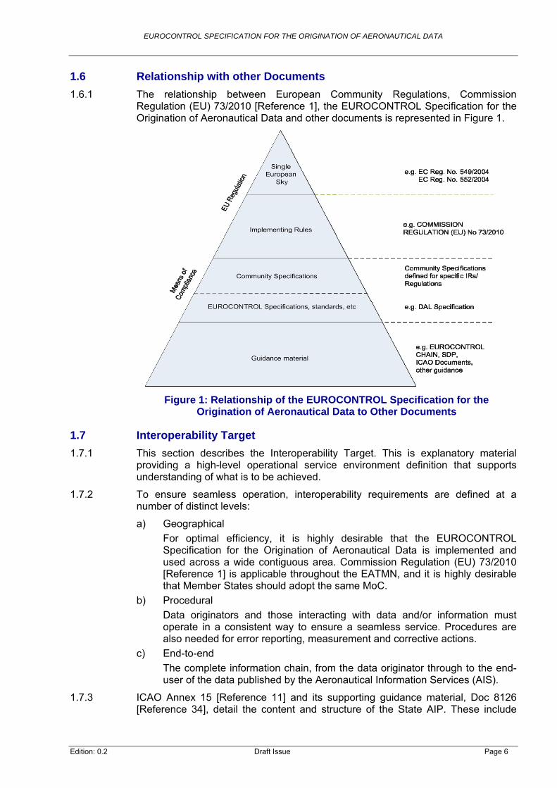
1.6.1 The relationship between European Community Regulations, Commission Regulation (EU) 73/2010 [Reference 1], the EUROCONTROL Specification for the Origination of Aeronautical Data and other documents is represented in Figure 1.
Figure 1: Relationship of the EUROCONTROL Specification for the Origination of Aeronautical Data to Other Documents
1.7 Interoperability Target
1.7.1 This section describes the Interoperability Target. This is explanatory material providing a high-level operational service environment definition that supports understanding of what is to be achieved.
1.7.2 To ensure seamless operation, interoperability requirements are defined at a number of distinct levels:
a) Geographical
For optimal efficiency, it is highly desirable that the EUROCONTROL Specification for the Origination of Aeronautical Data is implemented and used across a wide contiguous area. Commission Regulation (EU) 73/2010 [Reference 1] is applicable throughout the EATMN, and it is highly desirable that Member States should adopt the same MoC.
b) Procedural
Data originators and those interacting with data and/or information must operate in a consistent way to ensure a seamless service. Procedures are also needed for error reporting, measurement and corrective actions.
c) End-to-end
The complete information chain, from the data originator through to the end-user of the data published by the Aeronautical Information Services (AIS).
1.7.3 ICAO Annex 15 [Reference 11] and its supporting guidance material, Doc 8126 [Reference 34], detail the content and structure of the State AIP. These include
Edition: 0.2 Draft Issue Page 6

EUROCONTROL SPECIFICATION FOR THE ORIGINATION OF AERONAUTICAL DATA
data quality requirements for a limited set of the data in the scope of ICAO Annex 15.
1.7.4 Commission Regulation (EU) 73/2010 [Reference 1] addresses electronic data processes and provision of data, and it supplements and strengthens the requirements of ICAO Annex 15 [Reference 11] in order to:
a) ensure the implementation of provisions for assuring aeronautical data/information quality (accuracy, resolution, integrity), completeness, consistency and timeliness;
b) describe the performance requirements for how data should be originated, transferred from one party to another, and how data should be automatically handled and processed. In particular, the provisions have to ensure achievement of the necessary levels of integrity, security and validation.
1.7.5 To enable the Interoperability Target to be reached, this EUROCONTROL Specification specifies a MoC for the origination of aeronautical data.
1.7.6 References are made to external standards and documents maintained by other bodies. This is, in particular, related to the content of the IAIP, electronic terrain and obstacle data and aerodrome mapping data, based on ICAO Annex 15 [Reference 11] and ICAO Doc 8126 [Reference 34].
1.8 Responsible Unit
1.8.1 This EUROCONTROL Specification will be maintained by the Single European Sky Unit in cooperation with the NAV/CNS Research Unit.
Edition: 0.2 Draft Issue Page 7
EUROCONTROL SPECIFICATION FOR THE ORIGINATION OF AERONAUTICAL DATA
Edition: 0.2 Draft Issue Page 8
2 (Normative) Specification for Data Origination Requirements
2.1 Introduction
2.1.1 As detailed in Section 1.4, the conventions for denoting requirements, recommendations and optional requirements in this Chapter are as follows:
‘Shall’ - indicates a statement of specification, the compliance with which is mandatory to achieve the implementation of the EUROCONTROL Specification. It indicates a requirement which must be satisfied by all systems claiming conformity to this EUROCONTROL Specification7. Such requirements shall be testable and their implementation auditable.
‘Should’ - indicates a recommendation or best practice, which may or may not be satisfied by all systems claiming conformity to this EUROCONTROL Specification.
‘ ’ – indicates an optional element. May
2.1.2 It should be noted that to improve the readability, document references are not provided in this normative chapter. However, all documents referred to within this section are listed in Chapter 6.
2.2 General Requirements
2.2.1 Data Quality
2.2.1.1 General
2.2.1.1.1 All data shall be originated in a manner which meets the defined data quality requirements for the data item, in accordance with Article 6 of Commission Regulation (EU) 73/2010.
DO-DQR-010
Note: The minimum data quality requirements are detailed in the EUROCONTROL Data Quality Requirements (DQR) Specification. Those that are not present in the harmonised list shall be derived by each State using an appropriate safety assessment process, as described in the EUROCONTROL DQR Specification.
2.2.2 Reference System Specification
2.2.2.1 Horizontal Reference System
2.2.2.1.1 The horizontal reference system for the publication of all co-ordinate data shall be the World Geodetic System-1984 (WGS-84).
DO-REF-010
Note : Access to WGS-84 has historically been difficult to realise with centimetre precision. However, the WGS-84 co-ordinate system is aligned with the International Terrestrial Reference System (ITRS), realised through the
(1)
7 A demonstration of conformity with this EUROCONTROL Specification will bring about a presumption of conformity to regulatory provisions for which the specification has been formally recognised as a MoC. These provisions are identified in Article 6(4), (5) and (6).

EUROCONTROL SPECIFICATION FOR THE ORIGINATION OF AERONAUTICAL DATA
Edition: 0.2 Draft Issue Page 9
International Terrestrial Reference Frame (ITRF) at a defined epoch. ICAO Annex 15 identifies the ITRF 2000 specification (i.e. frame ITRF 2000, at epoch January 01, 2000) as the appropriate epoch, where ITRF is used,
Note(2):
(although ICAO Annex 15 uses the
Note(3):
, the quality of the data is not expected to be
2.2.2.1.2
co-ordinates in a world-wide, consistent reference frame (WGS-84 / ITRF 2000).
2.2.2.1.3 restrial reference frame which is connected to ITRF via transformation
2.2.2.1.4 The version of the horizontal reference frame used shall be rec
2.2.2.1.5 rigination shall be recorded, together with the co-ordinates, as (lineage) metadata.
DO-REF-050
2.2.2.2.1 data points shall be expressed as a height relative to Mean Sea Level (MSL).
Note: ces between a point and the
2.2.2.2.2 eet the ICAO requirements shall be used to determine the MSL reference surface.
for the determination of horizontal co-ordinates.
Further explanation and guidance is provided in Annex F. The terms WGS-84 and ITRF are used synonymously in this EUROCONTROL Specification. For this practical reason, the term ITRF 2000 is predominantly used in the document term WGS-84 for historical reasons).
The Infrastructure for Spatial Information in Europe (INSPIRE) directive8 requires that the European Terrestrial Reference System 1989 (ETRS89) shall be the datum used for spatial data sets. Within the geographical scope of ETRS89, the use of ETRS89 as the datum for the aviation domain should be considered for data storage and to transform data to ITRF for publication. For practical reasons associated with the densification of European Terrestrial Reference Frame 1989 (ETRF89), a survey relative to ETRF89 is often easier than to ITRF. Since appropriate transformations are availableimpacted by this approach.
If aeronautical data items have been surveyed in a different ITRF version to ITRF 2000, or in any other reference frame, the appropriate ITRF transformation shall be applied to the data to produce
DO-REF-020
The reference system used in data origination shall be a dynamic ter parameters.
DO-REF-030
orded as metadata9.
DO-REF-040
The horizontal reference frame used in data o
2.2.2.2 Vertical Reference System
All surveyed vertical aeronautical
DO-REF-060
For the documentation of the vertical distanMSL, the term ‘elevation’ is used in aviation.
A geoid model sufficient to m
DO-REF-070
8 Commission Regulation (EU) No 1089/2010 of 23 November 2010 implementing Directive 2007/2/EC. 9 More information on metadata and quality reporting can be found in section 2.3.8.3.
EUROCONTROL SPECIFICATION FOR THE ORIGINATION OF AERONAUTICAL DATA
Edition: 0.2 Draft Issue Page 10
2.2.2.2.3 vailable in compliance with the
International Organisation for Standardisation’s (ISO) information -- Spatial referencing by coordinates”.
2.2.2.2.4 model (i.e. other than EGM-96) is based on a different horizontal reference system than WGS-84, the geoid undulatransformed to WGS-84.
2.2.2.2.5 The geoid model used for the expression of elevations relarecorded in the metadata.
2.2.2.2.6 The information about the geoid model used shall be recovalues as metadata.
2.2.2.2.7 Where a different geoid model than EGM-96 is used, the referof the model shall be recorded in the metadata.
DO-REF-120
2.2.2.3.1 temporal reference system used for aeronautical data shall be the Gregorian calendar and Co-ordinated Universal Time (UTC), in accordan15.
DO-REF-130
2.2.2.4.1 The units of measurement in which data is provided shall bICAO Annex 5.
10
2.2.2.4.2 For all numerical data, the unit of measurement shall be recor
2.2.2.4.3 xagesimal degrees (Degrees Minutes Seconds and decimals of a Second) to the resolutions requirdata quality requirements for the data item.
2.2.2.4.4 rded in the form of decimal degrees (Degrees and decimals of a Degree) to the meet the defined data quality requirements for the data item.
OM-040
2.2.2.4.5 nces shall be recorded in one of the following units:
Where a geoid model other than the Earth Gravitational Model (EGM) 1996 (EGM-96) is used, the geoid model shall be made a
19111 “Geographic
DO-REF-080
Note: One possible implementation of “making available” is to provide a raster data set where, for each cell, the geoid undulation value is provided.
Where a non-global geoidtion values shall be
DO-REF-090
tive to MSL shall be
DO-REF-100
rded for all elevation
DO-REF-110
Note: Annex G provides further information on vertical reference systems and issues related to the determination of geoid undulations.
ence to the originator
2.2.2.3 Temporal Reference System
The ce with ICAO Annex
2.2.2.4 Units of Measurement
e in accordance with
DO-UOM-0
ded as metadata.
DO-UOM-020
Positions shall be recorded in the form of seed to meet the defined
DO-UOM-030
Bearings, azimuths and magnetic variations shall be recoresolutions required to
DO-U
Dimensions and dista

EUROCONTROL SPECIFICATION FOR THE ORIGINATION OF AERONAUTICAL DATA
Edition: 0.2 Draft Issue Page 11
a) Metres (m);
b) Feet (ft);
c) Kilometres (km);
DO-UOM-060
2.2.2.4.7 As an alternative to the primary unit for distances over 4,000
DO-UOM-080
2.2.2.4.9 As an alternative to the primary units for elevations, altitudes and he
DO-UOM-090
2.2.2.4.10 ith ICAO, all calculated and derived vertical references shall be :
b) Above Ground Level (AGL), or
c) Flight Level (FL).
DO-UOM-100
ifications
2.2.3.1
2.2.3.1.1 tended user in accordance with a common data set specification which
meets the provisions in Article 4 and Annex I of Commiss
DO-DSS-010
ission Regulation (EU) 73/2010.
2.2.3.1.2 The data set specification used to exchange aeronautical datdocumented.
2.2.3.2 Electron
Note(1): provisions of Annex I
Note(2):
d Aerodrome Mapping
d) Nautical Miles (NM).
DO-UOM-050
2.2.2.4.6 The primary unit for distances over 4,000 metres shall be kilometres.
metres, nautical miles may be used.
DO-UOM-070
2.2.2.4.8 The primary unit for elevations, altitudes and heights shall be metres.
ights, feet may be used.
In accordance wexpressed in one of the following units
a) MSL,
2.2.3 Data Set Spec
Introduction
Those Air Navigation Service Providers (ANSPs) originating data shall provide it to the next in
ion Regulation (EU) 73/2010.
Note: Clearly defined data models exist for the data within the scope of Comm
a/information shall be
DO-DSS-020
Integrated Aeronautical Information Package, Aerodrome Mapping Data and ic Obstacle Data
The Aeronautical Information Exchange Model (AIXM) Conceptual Model provides the detailed requirements which meet thePart A of Commission Regulation (EU) 73/2010, for the data sets within the scope of the IAIP and electronic obstacle data.
The aerodrome mapping exchange schema, as specified in the European Organisation for Civil Aviation Equipment’s (EUROCAE) ED-119A “Interchange Standards for Terrain, Obstacle, an

EUROCONTROL SPECIFICATION FOR THE ORIGINATION OF AERONAUTICAL DATA
Edition: 0.2 Draft Issue Page 12
Data”, meets the provisions in Annex I of Commission Regulation (EU)
2.2.3.3 Electron
Note: The Terrain Information Conceptual Model meets the provisions in Annex I rt B of Commission Regulation (EU) 73/2010 for electronic terrain data
2.2.3.4 Metadat
Note:
nation has been developed by the Aviation Domain Working
73/2010 Part A for aerodrome mapping data sets.
ic Terrain Data Sets
Pasets.
a
A metadata model profile for the aviation community, based on ISO 19115 and supporting the needs for aeronautical information collection, storage and dissemiGroup of the Open Geospatial Consortium (OGC). The profile is available on the OGC website (http://www.opengeospatial.org/standards/dp) and it comprises:
Requirements for aviation metadata, which detail the user
e Aviation Metadata Profile, which explains how to
2.2.4
2.2.4.1 The party requesting the origination, modification or withdrawspecify the data and the action to be applied to it by mea
DO-DPS-010
2.2.4.2
all be provided;
the data shall be provided to the
c) clearly identify the report format to be used;
DO-DPS-020
2.2.4.3 The data originator shall originate, modify or withdraw data i
2.2.4.4 The data originator shall ensure that the data that has been withdrawn in accordance with the Data Product Specificat
requirements for metadata in the aviation domain, based on ICAO SARPS, Commission Regulation (EU) 73/2010, European INSPIRE Directive, etc.
Guidance on thmap the requirements for aviation metadata into a metadata profile.
Data Product Specifications
al of data shall clearly ns of a Data Product
Specification.
The Data Product Specification shall:
a) clearly identify the entity to which the data sh
hich b) clearly identify the date and time by widentified entity;
d) include the data quality requirements.
n accordance with the Data Product Specification.
DO-DPS-030
originated, modified or ion is independently10
verified.
DO-DPS-040
10 Independence means that the verification should be undertaken by separate personnel to those that performed the origination.

EUROCONTROL SPECIFICATION FOR THE ORIGINATION OF AERONAUTICAL DATA
Edition: 0.2 Draft Issue Page 13
2.2.4.5 The data originator shall produce a report detailing the actions carried out in order to originate, modify or withdraw the data in accordance with the Data Product Specification.
2.2.4.6 The part withdrawal of data shall verify
Note(1): verification objectives are included in the EUROCONTROL l (DAL) Specification.
Note : The formal arrangements to be applied in the provision of the Data ecification are detailed in the EUROCONTROL DAL
2.2.5
2.2.5.1
2.2.5.1.1 is the term used in aeronautical navigation to define the difference between True North and Magnetic North.
eomagnetic model, such as the International Geomagnetic Reference Field .
2.2.5.1.3 of measurement and the annual rate of change of magnetic variation should be provided.
2.2.5.1.4 Station Navaid.
DO-CAT-030
is the difference between True North and the VHF Omnidirectional Radio Range (VOR) North Alignment and, unless the
has been aligned to True North, should not exceed 1.5° of the
2.2.5.2
2.2.5.2.1
2.2.5.2.1.1 :
that has been defined
The intersection of distances from three points.
b) Derived from source data that has been defined in WGS-84. For example:
DO-DPS-050
y requesting the origination, modification orthat the data originator has correctly implemented the Data Product Specification.
DO-DPS-060
Validation and Data Assurance Leve
(2)
Product SpSpecification.
Specific Categories of Data
Magnetic Variation
Magnetic Variation
2.2.5.1.2 Magnetic variation should be determined by the national geodetic agency derived from an appropriate g
11
DO-CAT-010
The date
DO-CAT-020
declination shall be provided by the service provider responsible for the
Note: The Station Declination
VOR current Magnetic Variation.
Calculated and Derived Data
Source Data
Co-ordinate data not determined by survey shall either be
a) Calculated using geodesic algorithms and source datain WGS-84. For example:
A bearing and distance from a point;
The intersection of bearings from two points;
11 See www.ngdc.noaa.gov/geomagmodels/Declination.jsp. Please note that the National Oceanic and
iation”. Atmospheric Administration (NOAA) uses the term “declination” in place of “var

EUROCONTROL SPECIFICATION FOR THE ORIGINATION OF AERONAUTICAL DATA
Edition: 0.2 Draft Issue Page 14
Manually selected points along a line of longitude
DO-CAT-040
2.2.5.2.1.2 The methods(s) employed to calculate or derive data s
-050
2.2.5.2.1.3 Before a data item is calculated/derived, it shall be ensured
DO-CAT-060
2.2.5.2.1.4 Conversions of distances and angular units shall be performe
mple of such an action is the conversion of metres to feet.
2.2.5.2.1.5 Distance and length data shall be determined either by dista
-CAT-080
2.2.5.2.1.6 Distance and length values shall be geodesic distances13, i.e.
lel to the equator as the earth is an oblate sphere
2.2.5.2.1.7 Bearing data shall be calculated using geodesic algorithms
DO-CAT-100
2.2.5.2.1.8
d) Specified by airspace designers, taking account of mi
to validate the calculated or derived data shall be documented.
or latitude;
Manually selected points determined “by definition”12.
hall be recorded as metadata.
DO-CAT
that the quality of the input data used is sufficient to achieve the required quality of the output data.
d in accordance with ICAO Annex 5.
DO-CAT-070
Note: An exa
nce measurement or by calculation.
DO
the shortest distance between any two points on a mathematically defined ellipsoidal surface.
DO-CAT-090
Note: The geodesic distance between two points is often referred to as great circle distance although strictly the only paths on the earth that are great circles are paths paral
and source data that has been defined in WGS-84.
Elevation/height/altitude data shall be:
a) Determined by geodetic survey (see section 2.3) or;
b) Determined by analysis of a suitable digital terrain model (see also Appendix G.2.5) or;
c) Calculated by adding specified values (e.g. Minimum Obstacle Clearance) to data determined in a) to b) above14 or;
nimum altitudes/flight levels determined in a) to c) above.
DO-CAT-110
2.2.5.2.1.9 Derived data shall be validated using appropriate means.
DO-CAT-120
2.2.5.2.1.10 The method used
12 Typical examples for suchs object are restricted airspaces or danger areas. 13 For a definition of “geodesic distance”, see ICAO Annex 15, Chapter 2. 14 For example, procedure design.

EUROCONTROL SPECIFICATION FOR THE ORIGINATION OF AERONAUTICAL DATA
Edition: 0.2 Draft Issue Page 15
DO-CAT-130
2.2.5.2.2 Specific Cases
2.2.5.2.2.3 The identifier for Prohibited, Restricted and Danger Areas shall be allocated by a
DO-CAT-160
2.2.5.3.1
2.2.5.3.1.1h as EUROCONTROL, or at a national level.
ventions determine, for example, the number of letters that should be the alphanumeric characters that may be used. Details of particular
ance on the identification of obstacles.
Annex 10
2.2.5.3.2.5
Note(1):
te Designators (ICARD) service for a new h ICAO's working
ew
Note(2): There is no agreed heliport indicator naming scheme.
2.2.5.2.2.1 The co-ordinates of the Global Navigation Satellite System (GNSS) service area shall be provided by the GNSS service supplier.
DO-CAT-140
2.2.5.2.2.2 The co-ordinates and vertical extents of Prohibited, Restricted and Danger Areas shall be provided by the authority responsible for the area.
DO-CAT-150
single national authority.
2.2.5.3 Naming / Identification
Generic
Naming and identification normally follow conventions established either at a global level by ICAO, by regional bodies, sucSuch conused andnaming conventions are found below.
2.2.5.3.2 Specific
Note: The EUROCONTROL Terrain and Obstacle Manual provides guid
2.2.5.3.2.1 Radio navigation aids shall be identified in accordance with ICAO Annex 10 Volume I and designated in accordance with ICAO Annex 11, Appendix 2.
DO-CAT-170
2.2.5.3.2.2 Special navigation systems shall be identified in accordance with ICAOVolume I.
DO-CAT-180
2.2.5.3.2.3 GNSS shall be identified in accordance with ICAO Annex 10 Volume I.
DO-CAT-190
2.2.5.3.2.4 Significant points shall be identified in accordance with ICAO Annex 11, Appendix 2.
DO-CAT-200
All current aerodrome and heliport location indicators and names shall be recorded in ICAO Doc 7910.
DO-CAT-210
The State body responsible for the allocation of aerodrome location indictors is required to make a proposal to ICAO through the ICAO International Codes and Rouaerodrome location indicator, in accordance witinstructions. ICAO has the ultimate responsibility for the approval of a naerodrome location indicator.

EUROCONTROL SPECIFICATION FOR THE ORIGINATION OF AERONAUTICAL DATA
Edition: 0.2 Draft Issue Page 16
2.2.5.3.2.6 Runway designations shall meet the requirements of ICAO Annex 14 Volume I.
2.2.5.3.2.8 All Air Traffic Services (ATS) routes, other than Standard In(SIDs) and Standard Terminal Arrival Routes (STARs), s
DO-CAT-240
2.2.5.3.2.9 All SIDs and STARs shall be identified in accordance w
2.2.5.4
2.2.5.4.1 Textual elements shall be developed to be clear andunderstandable to users considering that the language used
DO-CAT-260
2.2.5.4.2 Irrespective of the associated data integrity level, all textu reviewed.
2.2.5.4.3
2.2.5.4.3.1 Any translation of text from one language to another shall b
e organisation’s Quality Management System.
2.2.5.4.3.2 Irrespective of the associated data integrity level, all translatviewed.
2.2.5.5
2.2.5.5.1 Abbreviations should be in accordance with ICAO Abbre
DO-CAT-300
2.2.5.5.2 Where other abbreviations are used, these shall be clearly e
DO-CAT-310
2.2.5.6 Radar Services and Procedures
DO-CAT-220
2.2.5.3.2.7 Airspaces shall be identified in accordance with ICAO Annex 11.
DO-CAT-230
strument Departures hall be identified in
accordance with ICAO Annex 11, Appendix I.
ith ICAO Annex 11, Appendix 3.
DO-CAT-250
Textual Elements
unambiguous and may not be the first
language of the user.
al elements shall be independently
DO-CAT-270
Translation
e undertaken by staff with a suitable level of competence.
DO-CAT-280
Note(1): The level of competence needed to support the translation tasks needed should be identified in the competence management framework needed as part of th
Note(2): Ideally, translation should be performed into the mother tongue of the translator.
ions shall be independently re
DO-CAT-290
Abbreviations
viations and Codes (PANS-ABC (Doc 8400)).
xplained and listed in the National AIP.
2.2.5.6.1 Relevant communication failure procedures shall be developed.
EUROCONTROL SPECIFICATION FOR THE ORIGINATION OF AERONAUTICAL DATA
Edition: 0.2 Draft Issue Page 17
DO-CAT-320
2.2.5.6.2 Communication failure procedures shall be in accordance with ICAO Annex 6 and ICAO Doc 4444.
DO-CAT-330
2.2.5.6.3 The origination of Secondary Surveillance Radar (SSR) co Originating Region Code Assignment Method
2.2.5.7 Noise Abatement Procedures
2.2.5.7.1 tor for each aircraft
2.2.5.7.2 by the State of the operator.
2.2.5.7.3 noise ob
DO-CAT-370
Noise abatement procedures at aerodromes and heliports are developed
2.2.5.8 Charts
2.2.5.8.1 chart, sh
Note(1): plied with in all cases, . It is
AO Annex 4 compliant, meets user needs.
Note(2): Guidance on the preparation of the chart is detailed in
2.2.5.8.2 Annex 4,
DO-CAT-390
Note: The application of these symbols is detailed in ICAO Doc 869
de allocation blocks shall be co-ordinated with the(ORCAM) Users Group.
DO-CAT-340
A noise abatement procedure15 shall be developed by the operatype.
DO-CAT-350
Note: Advice may be needed from the aircraft manufacturer.
The noise abatement procedure shall be agreed
DO-CAT-360
The departure procedure to be used on a specific departure should satisfy the jectives of the State of the aerodrome.
Note: by the Airport Operator and, where necessary, in conjunction with the procedure design office.
The requirements of ICAO Annex 4 related to the content and layout of the relevant ould be met.
DO-CAT-380
It is recognised that if ICAO Annex 4 is to be comthe density of information to be portrayed on some charts is significantis, therefore, acknowledged that, in some cases, the content of chartsamended to reduce clutter and, hence, produce a chart that, although not fully IC
ICAO Doc 8697.
Wherever possible, chart symbols shall be in accordance with ICAO Appendix 2.
7.
2.2.5.8.3 As far as practicable, States should avoid the need to use symbols that are not specified in ICAO Annex 4.
15 Noise abatement procedures should not be confused with instrument flight procedures. Typically, noise abatement procedures define how thrust and flap are managed during the initial departure, normally up to 3,000ft, to avoid environmental issues regarding noise pollution whilst executing an Instrument Flight Procedure (IFP).

EUROCONTROL SPECIFICATION FOR THE ORIGINATION OF AERONAUTICAL DATA
Edition: 0.2 Draft Issue Page 18
DO-CAT-400
2.2.5.8.4 Where a new symbol, not detailed in ICAO Annex 4, is required, this shall be developed taking into account human factors considerations and already existing symbols.
DO-CAT-410
2.2.5.8.5 Any new symbol developed shall be assessed to ensure that it is not similar to and, therefore, easily confused with, existing symbols, consideringICAO Annex 4 and those already defined by the State.
DO-CAT-420
DO-CAT-430
2.2.5.9
2.2.5.9.1 Data wh e shall not be permanently removed from storage but marked as withdrawn.
DO-CAT-440
2.2.6
2.2.6.1 Any processing of aeronautical data/information shall be in compliance with Article 6(7) of Commission Regulation (EU) 73/2010.
DO-PRO-010
2.2.7
2.2.7.1 Data sha direct electronic transmission, in accordance with the
Note(1): are detailed in the EUROCONTROL
which offer a means of compliance with the data exchange objectives of the EUROCONTROL DAL Specification are
2.2.7.2
2.2.7.3 the perf 5(2) and Annex II of Commission
DO-EXC-030
Note: For data originators other than ANSPs, it may not bwith the above cited requirements.
all those specified in
2.2.5.8.6 The meaning of new symbols shall be clearly explained.
Withdrawn Data
ich is no longer effectiv
Note: The EUROCONTROL DAL Specification details objectives to be met for the withdrawal of data.
Data Processing
Note: Objectives for the processing of data are included in the EUROCONTROL DAL Specification.
Data Exchange
ll be exchanged byprovisions of Article 5 of Commission Regulation (EU) 73/2010.
DO-EXC-010
Objectives for the exchange of data DAL Specification.
Note(2): Requirements detailed in the
EUROCONTROL AIX Specification.
A data exchange format should be agreed for the provision of data by data originators to ANSPs.
DO-EXC-020
Where possible, the data exchange format for the provision of data should meet ormance requirements of Article
Regulation (EU) 73/2010.
e possible to comply
EUROCONTROL SPECIFICATION FOR THE ORIGINATION OF AERONAUTICAL DATA
Edition: 0.2 Draft Issue Page 19
2.2.7.4 The means and format for data exchange shall be documented in the formal arrangements established between the sending and receiving party.
ents shall be in accordance with Article 6(3) and Annex IV Regulation (EU) 73/2010.
2.2.8 Quality Assurance
2.2.8.1 Commis
Note(1):
Note : Guidance on implementing a Quality Assurance system for Instrument ure Design is provided in the ICAO Doc 9906 (Quality
Assurance Manual for Flight Procedure Design, Volume 1 Flight rocedure Design Quality Assurance System).
2.2.9.1
2.2.9.1.1 Where software and tools are used in the origination and
12 of Co
Note(1): ONTROL DAL Specification.
ote(3): Guidance on the validation of instrument flight procedure design tools is provided in ICAO Doc 9906 (Quality Assurance Manual for Flight
2.2.9.1.2 Where the manufacturer has not performed a conformity
DO-TSW-020
2.2.9.1.3 Where the techniques employed supports independent ch
DO-TSW-030
2.2.9.1.4 In place of a manual computation check, the verification of the
DO-EXC-040
2.2.7.5 The formal arrangemPart C of Commission
DO-EXC-050
In originating, managing and distributing data, the quality assurance provisions of sion Regulation (EU) 73/2010 shall be met.
DO-QUA-010
Objectives for quality assurance are included in the EUROCONTROL DAL Specification which may be used as a suitable means of compliance.
(2)
Flight Proced
P
2.2.9 Tools and Software
General
processing of data, it shall be demonstrated that these function in compliance with Article 8 and Article
mmission Regulation (EU) 73/2010.
DO-TSW-010
Objectives which offer a means of compliance for the use of tools and software are detailed in the EUROC
Note(2): It is recommended that responsibility for confirming that the tool complies with the relevant provisions in Commission Regulation (EU) 73/2010 be assigned to the tool manufacturer.
N
Procedure Design), Volume 3 (Flight Procedure Design Software Validation).
assessment of the software, it shall be the responsibility of the user to ensure the conformity of the software before it is used for originating and processing data.
ecking using manual computation, this type of check shall be used to verify the correct use of the software prior to its first use.
software may be carried out by an independent survey, allowing comparison of the calculated co-ordinates with the measured values.

EUROCONTROL SPECIFICATION FOR THE ORIGINATION OF AERONAUTICAL DATA
Edition: 0.2 Draft Issue Page 20
DO-TSW-040
2.2.9.1.5 Where the verification of the softwaaccuracy and reliability of the con
re is carried out by an independent survey, the trol survey shall be such that there is a high
2.2.10 Data Validation and Verification
2.2.10.1 integrity V Part B
of compliance with Article 6(2) and Annex IV Part B are detailed in the EUROCONTROL DAL Specifica
2.2.10.2 or calcu art D of Commission Regulation (EU) 73/2010.
DO-VAL-020
cle 6(4) and Annex ion.
2.3 Survey
2.3.1
2.3.1.1.1 The spatial accuracy should not be worse than the tolerance values.
DO-SVY-010
Note: The table below provides example t s for 90% and 95% c nce level
probability that an error produced by a tool or software can be detected.
DO-TSW-050
Data validation and verification processes shall be adequate for the assigned level of the data item, in accordance with Article 6(2) and Annex I
of Commission Regulation (EU) 73/2010.
DO-VAL-010
Note: Objectives which offer a meanstion.
Aeronautical data/information shall be validated and verified prior to use in deriving lating other data, in accordance with Article 6(4) and Annex IV P
Note: Objectives which offer a means of compliance with ArtiIV Part D are detailed in the EUROCONTROL DAL Specificat
Facilities and Corresponding Minimum Data Requirements
olerance valueonfide s16.
Confidence Routine Essential Critical
90% 3.5 3 (no such data)
95% 3 2 1.5
Table 1: Tolerance Values (Multipliers) for Aeronautical Data
The survey method for the origination of a feature’s co-ordinate shall2.3.1.1.2 be capable of meeting the data quality requirements.
2.3.1.1.3 ation of a feature’s co-ordinate shall be validated to ensure that it is capable of meeting the data quality requirements.
DO-SVY-030
DO-SVY-020
The survey method for the origin
16 Reading: Based on the integrity requirement (Critical), a 95% confidence level and the accuracy requirement (1m), the tolerance for a runway threshold is 1.5m. For an Area 2 obstacle (routine, 90 %confidence, 3m accuracy) the tolerance is 10.5m. The values are based on what should be technically feasible and on requirements in cadastral survey law (CH).

EUROCONTROL SPECIFICATION FOR THE ORIGINATION OF AERONAUTICAL DATA
Edition: 0.2 Draft Issue Page 21
2.3.1.1.4 Organisations should follow best practice guidelines in Annex K to this
2.3.1.2 Calibration of Survey Equipment
2.3.1.2.1
the accu
Note: Objectives which offer a means of compliance for the calibrequipment are detailed in the EUROCONTROL DAL
hen surveying obstacles from an airborne or space-borne sensor platform.
2.3.1.2.4 Equipment calibration shall be shown to be valid for the time of use.
DO-SVY-080
DO-SVY-090
2.3.2 Handling of Data
2.3.2.2 epoch be
rrect” refers to the requirement for the reference points, permanent reference network (if available) and publication eline.
2.3.2.4
affected
Note: Independent redundant measurements of the information or of known points are considered an effective mean to detect g
data model for aviation features in the sensor software should
EUROCONTROL Specification.
DO-SVY-040
All survey equipment deployed in relation to surveys covered by this EUROCONTROL Specification shall be shown to be calibrated and to perform to
racy appropriate to the task.
DO-SVY-050
ation of survey Specification.
2.3.1.2.2 Sensor calibration instructions shall be based on the requirements of the survey method and the sensor manufacturer’s requirements.
DO-SVY-060
2.3.1.2.3 A radiometric calibration of a sensor system should be considered w
DO-SVY-070
2.3.1.2.5 Details of the calibration process and results shall be included in the survey report.
2.3.2.1 Reference point co-ordinates shall be loaded into the survey equipment by digital data transfer.
DO-SVY-100
The reference points utilised in survey equipment shall be evaluated for the correct fore being loaded.
DO-SVY-110
Note: The term “copoch to be in-
2.3.2.3 The data originator shall ensure that the measurements in the field are digitally captured and stored.
DO-SVY-120
Where information, such as lever arm or tripod height, cannot be measured by digital sensors, the surveyor shall provide evidence that such information is not
by a gross error.
DO-SVY-130
check surveys ross errors.
2.3.2.5 The use of a specificbe considered.
DO-SVY-140

EUROCONTROL SPECIFICATION FOR THE ORIGINATION OF AERONAUTICAL DATA
Edition: 0.2 Draft Issue Page 22
2.3.3
2.3.3.1 shall be maintained throughout the lifetime of each data item and for at least five years following the end
2.3.3.3 termediate results, etc) and records (survey report including data quality evaluation, metadata, etc) related to a
2.3.3.5
Note:
. The type of monitoring applied
, visual inspection may be sufficient or resurvey may be considered necessary.
2.3.3.6
Note:
The type of monitoring applied may depend on the location of
2.3.3.7 Monitoring and maintaining co-ordinate data shall include a
DO-SVY-210
2.3.3.8 Where the positional accuracy expressed as combined un
DO-SVY-220
Data Maintenance
Surveyed, calculated and derived data of that period or until
five years after the end of the period of validity for any data item calculated or derived from it, whichever is the latter.
DO-SVY-150
2.3.3.2 Surveyors shall digitally capture and store observations (raw data, etc), parameters and intermediate data.
DO-SVY-160
All information (parameter, in surveyed, calculated
or derived aeronautical data item shall be maintained with the data item throughout the lifetime of the data item.
DO-SVY-170
2.3.3.4 Surveyors shall make the observations available on the request of the commissioning organisation.
DO-SVY-180
All survey data assigned a data integrity level of critical or essential shall be monitored for changes on a yearly basis, as a minimum.
DO-SVY-190
Monitoring shall ensure that a survey item has not been shifted, for example, due to construction work. This monitoring should identify survey errors not detectable by single measurement or to confirm the measurements and the quality attributesmay depend on the location of the data and how easily a change may be detected within it. For example
All survey data assigned a data integrity level of routine should be monitored for changes every five years, as a minimum.
DO-SVY-200
Effective notification procedures can help reduce the workload for monitoring the changes to obstacles not situated at or around an aerodrome. the data and how easily a change may be detected within it. For example, visual inspection may be sufficient or resurvey may be considered necessary.
periodic review of the difference between the latest ITRF version required by ICAO and the reference frame used in the original survey.
certainty of measurements exceeds the accuracy requirement for that co-ordinate, re-survey (recalculation) of the relevant data shall be undertaken.
EUROCONTROL SPECIFICATION FOR THE ORIGINATION OF AERONAUTICAL DATA
Edition: 0.2 Draft Issue Page 23
Note: The document ‘Guide to the Expression of Uncertainty in Measurement’ (JCGM 100:2008) provides material on how to determine the uncertainty of a measurement.
2.3.3.9 Each State shall determine its own requirements for the frequency at which data
2.3.4
2.3.4.1 Where co-ordinates in a local co-ordinate frame which m
2.3.4.2 n
ld be taken into account that the positional quality may be degraded in subsequent processes.
DO-SVY-260
2.3.4.4 The reliability of the origination of co-ordinate data, taking int
DO-SVY-270
2.3.4.5 All survey observations should be made and recorded wit
DO-SVY-280
2.3.4.6 All survey data assigned a data integrity level of critical shall b
DO-SVY-300
2.3.4.8 Where it is operationally beneficial to work in a local (planar
DO-SVY-320
items are completely re-surveyed.
DO-SVY-230
General Requirements and Survey Principles
eet the data quality requirements are converted to ITRF mathematically, the conversion process shall be shown to be such that the required data quality requirements are maintained.
DO-SVY-240
Survey accuracies shall be such that the uncertainties of each observation are sufficie tly small that the data quality requirements are met.
DO-SVY-250
Note: It shou
2.3.4.3 Additional observations may be made to increase the reliability of the measurement.
o account the survey method, the survey set-up and environmental conditions, shall be sufficient to meet the data quality requirements.
h the resolution and accuracy of the equipment used, so that future requirements for surveys of greater accuracy may be met.
e subject to sufficient additional measurement to identify survey errors not detectable by single measurement.
DO-SVY-290
2.3.4.7 Additional measurements should be as independent as possible, for example, using a different set-up, sensor or operator.
) co-ordinate system, evidence shall be given that the transformation to and from the local co-ordinate system does not impact the accuracy.
DO-SVY-310
2.3.4.9 When a planar co-ordinate system is used in the data origination or data processing, it should be Universal Transverse Mercator (UTM).

EUROCONTROL SPECIFICATION FOR THE ORIGINATION OF AERONAUTICAL DATA
Edition: 0.2 Draft Issue Page 24
2.3.4.10 All projection parameters of the planar co-ordinate system shall be recorded in the metadata associated with the co-ordinates to allow unambiguous reconstruction of the projection.
2.3.4.11 ta.
hall contact the National administration responsible if bout any of the facilities described in Annex I and
NTROL Specification.
2.3.5
2.3.5.1.1
t appropriate for the application and techniques proposed, a network of survey control stations shall
2.3.5.1.3 The geo control
DO-SVY-380
Note: The origination of terrain and obstacle data in difficult top
2.3.5.1.4 Survey cstability tility in subsequent surveys.
DO-SVY-390
2.3.5.2 Geodetic Control Network Quality Requirements
transfer, ation (EU) 73/2010, shall be
DO-SVY-400
2.3.5.2.2 lfil the following data quality requirements:
o ITRF: 0.10m;
3) Confidence Level 95 %; -8
5) Posi
DO-SVY-330
Any additional observation, such as weather (barometric pressure, temperature and wind, etc), should be recorded in the metada
DO-SVY-340
2.3.4.12 The surveying organisation sit requires any clarification aAnnex J of this EUROCO
DO-SVY-350
Geodetic Control Network
2.3.5.1 General Requirements
When a geodetic control network exists which meets the requirements listed in sections 2.3.5.1 and 2.3.5.2, it shall be used.
DO-SVY-360
2.3.5.1.2 Where no geodetic network exists which allows the accurate and reliable geodetic connection to ITRF or the geodetic network is no
be established.
DO-SVY-370
detic control network should consist of a minimum of four survey stations in order to provide sufficient redundancy.
ography or in densely populated areas may require more survey control stations.
ontrol stations should be strategically located so as to provide maximum and maximum u
Note: The monuments of existing aerodrome/heliport geodetic control networks may be used for the purposes laid down in this EUROCONTROL Specification.
2.3.5.2.1 The most stringent process requirements (data validation, digital datametadata, etc), as required by Commission Regulconsidered for survey control stations.
Survey control stations shall fu
1) Positional accuracy with respect t
2) Vertical accuracy: 0.05m;
4) Integrity: 1 x 10 (critical);
tional resolution 1/1000sec;

EUROCONTROL SPECIFICATION FOR THE ORIGINATION OF AERONAUTICAL DATA
Edition: 0.2 Draft Issue Page 25
6) Verti
DO-SVY-410
requirements of runway thresholds. The accuracy of survey control stations should be three times higher than the features to
2.3.5.2.3
DO-SVY-420
2.3.5.2.4 The distance between the survey control stations and the
do not conflict with the accuracy requirement of the item to be surveyed.
2.3.5.2.5 monitored for changes, as a minimum, yearly.
2.3.5.2.6 dertaken.
DO-SVY-460
2.3.5.2.8 If the newly computed value of a survey control station’s position haed value, then the station’s position to the standards laid down in this
ification.
2.3.5.3
2.3.5.3.1.1 stations shall be made permanently stable by using a monumentation appropriate to the location and the ground beneath it.
2.3.5.3.1.2 The surv(See An
DO-SVY-490
er the guidance of the National administration, to decideappropriate type.
2.3.5.3.1.3 Investigation should be made prior to the installation of survey control stations to ensure that underground cables and services are not affected by the installation.
cal resolution: 1cm.
Note: These data quality requirements are derived from the data quality
be surveyed in order to support their accuracy requirements.
The survey control network shall have an internal relative precision of better than 0.05m.
items to be surveyed shall ensure that the combined uncertainties of measurement (i.e. the predicted spatial accuracy)
DO-SVY-430
The positions of the survey control stations shall be
DO-SVY-440
Where changes in the positions of the survey control stations are detected, re-survey of the relevant positions shall be un
DO-SVY-450
2.3.5.2.7 The validation of the survey control stations should be based on internal vectors (between the survey control stations) or between survey control stations and national or international control stations.
s changed by 50mm or more when compared to the publishshall be re-measured and verified according EUROCONTROL Spec
DO-SVY-470
Monumentation of Survey Control Stations
2.3.5.3.1 Station Construction
Survey control
DO-SVY-480
ey control stations shall consist of standard types of survey monument nex F).
Note: Different types of monument will be appropriate for different locations and ground conditions at the aerodrome/heliport. It is for the surveyor, und
on the most

EUROCONTROL SPECIFICATION FOR THE ORIGINATION OF AERONAUTICAL DATA
Edition: 0.2 Draft Issue Page 26
DO-SVY-500
2.3.5.3.1.4tations, station monumentation should be as durable and secure as
is practicable.
DO-SVY-510
2.3.5.4.1 ll carry a unique identifier that does not repeat one that has been previously used.
Note: n in approximately the same
2.3.5.4.2 ring should be such that there is no doubt about the identity of the survey station.
2.3.5.4.3 ion (FIR) for which the geodetic
control network is designed (see also Annex H).
DO-SVY-540
2.3.5.5.1 ontrol station descriptions shall be prepared for easy and accurate identification.
2.3.5.5.2 control station showing background detail should be included in the description.
2.3.5.5.3 tion description shall be made available in the metadata of the control network.
2.3.5.5.4 incipal topographic features,
should be prepared as part of the station description.
DO-SVY-580
2.3.5.6.1
measurement do not conflict with the accuracy requirement of
2.3.5.6.2 all be measured to a minimum of two points on an appropriate geodetic
network.
DO-SVY-600
Where the geodetic control network consists of fewer than the recommended four survey control s
2.3.5.4 Survey Control Station Numbering
Each survey control station sha
DO-SVY-520
This will ensure that, where a station has been destroyed and subsequently replaced by a new statiolocation, misidentification does not occur.
The physical survey control station labelling and numbe
DO-SVY-530
The unique identifier for a survey control station shall include the ICAO code for the aerodrome / heliport or Flight Information Reg
2.3.5.5 Station Descriptions
Comprehensive aerodrome survey c
DO-SVY-550
A photograph of the survey
DO-SVY-560
The complete survey control sta
DO-SVY-570
An aerodrome geodetic control network plan, of a small scale for example, 1:2000, indicating the location of all survey stations and pr
2.3.5.6 Determination of Control Co-ordinates
Survey measurements shall be taken to connect the aerodrome geodetic control network to the ITRF geodetic frame in such a way that the uncertainties of
the control network.
DO-SVY-590
For each control station in the geodetic network, static relative positioning GNSS vectors sh

EUROCONTROL SPECIFICATION FOR THE ORIGINATION OF AERONAUTICAL DATA
Edition: 0.2 Draft Issue Page 27
2.3.5.6.3 Three or more points should be used for the connection to ITRF.
DO-SVY-610
Note: Observation and post-processing guidelines for these operations are given in Annex K.
2.3.5.6.4 Full details of the connection of the control network to ITRF shall be included in the survey report.
DO-SVY-620
2.3.5.7 Determination of Local Relationship between the Known Existing Datum and ITRF
2.3.5.7.1 Where existing, relative surveys need to be related to ITRF (e.g. aerodrome obstacle surveys), and the local relationship (difference in latitude, longitude, orientation and scale) between the known, existing datum and ITRF has not been provided by the national geodetic agency, observations shall be taken to determine this.
DO-SVY-630
2.3.5.7.2 Evidence shall be provided that the accuracy of the local relationship between the known, existing datum and ITRF is commensurate with the required accuracy of the data to be transformed.
DO-SVY-640
2.3.5.7.3 The existing datum and the values and accuracies of the local relationship shall be recorded in the survey report.
DO-SVY-650
2.3.5.7.4 The transformation parameters from the existing datum to ITRF shall be recorded in the survey report.
DO-SVY-660
2.3.6 Survey Requirements for Facilities17
2.3.6.1 Radio Navigation Facilities
2.3.6.1.1 For radio navigation facilities, including Ground-Based Augmentation System (GBAS) reference stations, the centre of the transmitting antenna shall be surveyed, except where a different specific survey point is standardised for the facility, as indicated in Annex I.
DO-SVY-670
2.3.6.1.2 For radio navigation facilities not described in Annex I, the horizontal co-ordinates of the geometric centre of the facility antenna shall be surveyed.
DO-SVY-680
Note: The details of such facilities should be reported to EUROCONTROL for possible inclusion in future releases of this EUROCONTROL Specification.
2.3.6.1.3 The surveying organisation shall contact the National administration responsible if it requires any clarification about the facilities described in Annex I.
DO-SVY-690
17 Aerodrome facilities equate to those in Area 3 and Area 4 (See Annex I).

EUROCONTROL SPECIFICATION FOR THE ORIGINATION OF AERONAUTICAL DATA
Edition: 0.2 Draft Issue Page 28
2.3.6.1.4 For collocated VOR/Distance Measuring Equipment (DME) with a separation between antennas of greater than 30 metres, both antennas shall be surveyed.
DO-SVY-700
2.3.6.1.5 For collocated VOR/DME with a separation between antennas of 30 metres or less, the position of the DME element shall be taken as the position information of this item.
DO-SVY-710
2.3.6.1.6 Where it is not possible to connect directly to ITRF, the method of local connection shall be recorded in the survey report.
DO-SVY-720
2.3.6.2 Runway Centre Lines and Thresholds
2.3.6.2.1 For surveying purposes, the centre line reference point of a runway shall be the centre line of the defined landing area on the load-bearing surface.
DO-SVY-730
2.3.6.2.2 Where the edge of the runway is irregular, or connected to a taxiway, an appropriate theoretical line shall be selected, which best identifies the probable edge of the runway.
DO-SVY-740
Note: The theoretical line should never extend beyond the physical edge of the runways.
2.3.6.2.3 Where the thresholds are marked by appropriate threshold markers, then the centre of these, along the extension of the centre line, shall be taken as the threshold points18.
DO-SVY-750
2.3.6.2.4 Where no threshold marker exists, the threshold should be determined by the National administration and marked according to ICAO Annex 14.
DO-SVY-760
2.3.6.2.5 Where no threshold marker exists, the threshold has not been defined by the National administration, and there is no other indication of the threshold position, then the centre line of the threshold lights immediately in advance (in the direction of landing) of the threshold paint markings (piano keys) should be taken as the threshold.
DO-SVY-770
2.3.6.2.6 Where no threshold marker exists, the threshold has not been defined by the National administration, there is no threshold marker or threshold lighting, the surveyor shall select an appropriate point for survey, in accordance with Annex I.
DO-SVY-780
2.3.6.2.7 Survey witness marks may be installed to enable the threshold survey point to be re-established in the event of re-surfacing, re-painting or for verification purposes.
DO-SVY-790
18 See also the figures provided in Annex I.

EUROCONTROL SPECIFICATION FOR THE ORIGINATION OF AERONAUTICAL DATA
Edition: 0.2 Draft Issue Page 29
2.3.6.2.8 In addition to the thresholds points, two associated runway centre line points, at a separation of not less than 10% of the runway length, shall be surveyed to aid collinearity testing.
DO-SVY-800
2.3.6.2.9 Unless visual inspection or previous surveys indicate that the runway centre line is not a straight line, the surveyor shall use the collinearity to verify the accuracy of the runway threshold co-ordinates.
DO-SVY-810
2.3.6.2.10 Where a runway has a threshold at each end, the two thresholds and two further runway centre line points should be surveyed.
DO-SVY-820
2.3.6.2.11 Where it is obvious that the runway centre line is not a straight line, additional points should be measured to ensure the horizontal accuracy of the runway centre line.
DO-SVY-830
2.3.6.2.12 The collinearity should be determined for the group of four points in DO-SVY-820.
DO-SVY-840
2.3.6.2.13 The collinearity testing for straight runways shall show that the angular deviation between the two vectors is less than five-hundredths of a degree.
DO-SVY-850
2.3.6.2.14 If either collinearity testing fails or the runway centre line is not a straight line, then a full, independent survey of the threshold points shall be performed.
DO-SVY-860
2.3.6.2.15 The distance from the surveyed threshold point to the end of the paved surface at the near end of the runway shall be determined to an accuracy of 0.1m.
DO-SVY-870
2.3.6.2.16 The longitudinal19 slope(s) of the runway shall be determined by surveying all the points along the runway centre line where a slope change occurs.
DO-SVY-880
2.3.6.2.17 A representative set of points along the runway centre line shall be selected to allow the slope change to be detected.
DO-SVY-890
2.3.6.2.18 When any type of clearway is declared, the elevation of the runway at the start of the Takeoff Run Available (TORA) (see section 2.3.6.3) and the elevation of the far end of the clearway or clearway plane, as appropriate, shall be used in the calculation of the overall slope of the Takeoff Distance Available (TODA).
DO-SVY-900
19 Longitudinal slope means the slope extending in the direction of take-off along the length of the runway.

EUROCONTROL SPECIFICATION FOR THE ORIGINATION OF AERONAUTICAL DATA
2.3.6.3 Declared Distances
2.3.6.3.1 Aerodrome declared distances constitute the relevant distances for the application of the weight and performance requirements of the Air Navigation (General) Regulations in respect of aeroplanes flying for the purpose of public transport.
TORA: Takeoff Run Available: This is the length of runway available and suitable for the ground run of an aeroplane taking-off;
ASDA: Accelerate-Stop Distance Available: This is the length of TORA plus the length of any associated stopway;
TODA: Takeoff Distance Available: This is the length of TORA plus the length of any associated clearway;
LDA: Landing Distance Available: This is the length of runway available and suitable for the ground landing run of an aeroplane.
2.3.6.3.2 The start of the TORA, and, where appropriate, the end of any clearway and/or stopways that exist shall be indicated to the surveyor by an authorised representative of the Aerodrome Operator.
DO-SVY-910
2.3.6.3.3 The TORA, ASDA, TODA and LDA should be measured for each paved and unpaved runway direction in accordance with the data quality requirements.
DO-SVY-920
2.3.6.3.4 The distances shall be measured along the centre line of the runway and of any associated stopway and clearway.
DO-SVY-930
2.3.6.3.5 The end of the declared TORA, ASDA and LDA, the runway end safety area, and the required strip length and width shall be defined.
DO-SVY-940
Note: If the particular runway is served by an instrument approach procedure, the strip width to be applied when determining LDA will differ from that required for TORA and ASDA.
2.3.6.4 Derived Threshold Co-ordinates
2.3.6.4.1 Where a point has been selected for survey, which is not coincident with the runway threshold, but offset along the centre line, then the co-ordinates of the threshold shall be determined by the National administration.
DO-SVY-950
Note: A method of calculation for this task is shown in Annex L.
2.3.6.4.2 The newly derived threshold co-ordinates shall be submitted to the same collinearity check as specified in Paragraph 2.3.6.2.9.
DO-SVY-960
2.3.6.5 Taxiway and Stand/Checkpoints
2.3.6.5.1 General
2.3.6.5.1.1 For surveying purposes, the centre (mid-width) of the taxiway centre line marking, apron taxiline marking or the aircraft stand guide line marking shall be taken as the reference.
Edition: 0.2 Draft Issue Page 30

EUROCONTROL SPECIFICATION FOR THE ORIGINATION OF AERONAUTICAL DATA
Edition: 0.2 Draft Issue Page 31
DO-SVY-970
2.3.6.5.1.2 The points of commencement and end of each straight section of taxiways, apron taxilines and aircraft stand point guidance lines markings shall be surveyed.
DO-SVY-980
2.3.6.5.1.3 For curved sections of taxiways, apron taxilines and aircraft stand guide line markings, the commencement and end of the curved section centre line shall be surveyed together with the position of the centre point of the arc and either its radius or at least two additional points along the curve.
DO-SVY-990
2.3.6.5.1.4 In the case of a compound curve, the centre and radius of each arc and the commencement and end of each of the arcs shall be surveyed.
DO-SVY-1000
2.3.6.5.1.5 Where it is impracticable to survey the centre and radius of each arc and the commencement and end of each arc in the field20, a series of sequential points shall be surveyed along the curved section of the centre line with a maximum arc to chord distance not exceeding 0.25m for taxiways and 0.10 for apron taxilines and aircraft stand guide line markings.
DO-SVY-1010
2.3.6.5.1.6 Sufficient points should be surveyed to achieve the required accuracy along the lines.
DO-SVY-1020
2.3.6.5.1.7 The surveyor shall, in processing the data, conduct a graphical inspection of the survey points to ensure collinearity.
DO-SVY-1030
Note: A digital orthophoto21 can support the validation of curved line features.
2.3.6.5.2 Taxiways
2.3.6.5.2.1 For the guidance of aircraft entering or exiting the runway for take-off or landing, the point at which the radius of turn, prescribed by the appropriate authority for each taxiway, is tangential to the runway centre line and the point at which that radius of turn joins the taxiway centre line marking at a tangent shall be surveyed.
DO-SVY-1040
2.3.6.5.2.2 Where it is impracticable to survey the point at which the radius of turn22, prescribed by the appropriate authority for each taxiway, is tangential to the runway centre line and the point at which that radius of turn joins the taxiway centre line marking at a tangent in the field, a series of sequential points shall be surveyed along the curved section of the centre line of taxiways.
DO-SVY-1050
20 For example where taxiway is a compound curve. 21 An orthophoto is an aerial photograph geometrically corrected ("orthorectified") such that the scale is uniform: the photo has the same lack of distortion as a map (Source: Wikipedia). 22 For example in cases where the elements are not clearly identifiable.

EUROCONTROL SPECIFICATION FOR THE ORIGINATION OF AERONAUTICAL DATA
Note: The EUROCAE/RTCA document ED-99/DO-272 “User Requirements for Aerodrome Mapping Information” provides additional guidance on how to survey taxiways.
2.3.6.5.2.3 Where a taxiway centre line marking is provided on a runway that is part of a standard taxi route, or a taxiway centre line is not coincident with runway centre line, the following points shall be surveyed:
a) The point on the taxiway marking at which the taxiway enters the runway;
b) The points at which the taxiway deviates from a straight line;
c) The intersection of the taxiway centre line marking and boundary of each “block” that has been published as part of the airport movement and guidance control system; and
d) The point on the taxiway marking at which the taxiway exits the runway
DO-SVY-1060
2.3.6.5.2.4 In defining taxiways, the following points shall be surveyed at the centre of the centre line marking of each taxiway, as appropriate:
a) Intermediate holding positions and runway holding positions (including those associated with the intersection of a runway with another runway when the former runway is part of a standard taxi route) and for points established for the protection of sensitive areas for radio navigation aids;
b) Taxiway intersection markings;
c) Intersection of other taxiways, including taxiways as described in paragraph 2.3.6.5.2.3;
d) Intersection of “blocks” defined for surface movement, guidance and control systems;
e) Commencement and end of selectable taxiway lighting systems provided as part of the surface movement, guidance and control systems, where different from point d) above; and
f) At stop bars.
DO-SVY-1070
2.3.6.5.2.5 In defining a helicopter air taxiway, the centre of each air taxiway marker shall be surveyed, as appropriate.
DO-SVY-1080
2.3.6.5.3 Aircraft Standpoints
2.3.6.5.3.1 In defining the aircraft stands, the following points shall be surveyed at the centre of the guide line marking of the aircraft stands, as appropriate:
a) Taxilane centre lines;
b) Lead-in line(s);
c) Turning lines;
d) Straight section of the turning line;
e) Nosewheel stopping position;
f) True heading of the alignment bar; and
g) Lead-out line(s).
DO-SVY-1090
2.3.6.5.3.2 Where aircraft stands are utilised by more than one aircraft type and different guide line markings exist, a diagram shall be prepared by the surveyor showing the
Edition: 0.2 Draft Issue Page 32

EUROCONTROL SPECIFICATION FOR THE ORIGINATION OF AERONAUTICAL DATA
arrangement of the markings in use, together with an indication of the points surveyed.
DO-SVY-1100
Note: Where stands at an aerodrome/heliport are marked uniformly, only a single diagram need be prepared for those with common marking.
2.3.6.6 Navigation Checkpoints
2.3.6.6.1 For navigation checkpoints used for the validation of navigation systems, the nose wheel stopping position shall be surveyed in accordance with 2.3.6.5.3.
DO-SVY-1110
2.3.6.7 Road Holding Positions
2.3.6.7.1 In accordance with local requirements, significant points shall be surveyed to meet the needs of the surface movement guidance and control system for vehicular traffic on the movement area of the aerodrome.
DO-SVY-1120
2.3.6.8 All Other Aerodrome/Heliport Navigation Elements
2.3.6.8.1 For all other aerodrome/heliport navigation elements that require surveying, the geometric centre of the element shall be surveyed except where a different specific survey point is standardised for the element.
DO-SVY-1130
2.3.6.9 Heliport / Helipad Data
2.3.6.9.1 General
2.3.6.9.1.1 Heliport data shall be surveyed to meet the requirements of ICAO Annex 14 Volume II.
DO-SVY-1140
2.3.6.9.1.2 The heliport elevation shall be surveyed.
DO-SVY-1150 .
2.3.6.9.1.3 The position of the heliport reference point shall be surveyed.
DO-SVY-1160
2.3.6.9.2 Final Approach and Take-off (FATO)
2.3.6.9.2.1 The threshold co-ordinates of the Final Approach and Take-off (FATO) Area shall be surveyed.
DO-SVY-1170
Note(1): FATO marking or markers may be used.
Note(2): The FATO marking is a rectangular stripe with a length of 9 m or one-fifth of the size of the final approach and take-off area which it defines and a width of 1 metre.
Note(3): The FATO marking is white.
2.3.6.9.2.2 The centre points on each lateral limit of the FATO shall be surveyed.
DO-SVY-1180
Edition: 0.2 Draft Issue Page 33

EUROCONTROL SPECIFICATION FOR THE ORIGINATION OF AERONAUTICAL DATA
2.3.6.9.2.3 Where the centre points are not marked, they shall be determined by the corner co-ordinates.
DO-SVY-1190
2.3.6.9.2.4 From the centre points the following information related to the FATO shall be derived:
a) The true bearing;
b) The length;
c) The width;
d) The longitudinal slope.
DO-SVY-1200
2.3.6.9.2.5 Where appropriate, the elevation of each threshold of the FATO shall be surveyed.
DO-SVY-1210
2.3.6.9.3 Touchdown and Lift-off Area (TLOF)
2.3.6.9.3.1 Sufficient co-ordinates of the lateral limits of the Touchdown and Lift-off Area (TLOF) area shall be surveyed to enable the calculation of the following features:
a) The geometric centre;
b) The dimensions;
c) The slope;
d) The elevation.
DO-SVY-1220
Note: TLOF marking consists of a continuous white line with a width of at least 30 cm.
2.3.6.9.4 Aiming Point Marking
2.3.6.9.4.1 Where there is an aiming point marking (see Annex J.4), the geometric centre of the equilateral triangle shall be calculated by surveying the three corner points.
DO-SVY-1230
Note(1): An aiming point marking is provided at a heliport where it is necessary for a pilot to make an approach to a particular point before proceeding to the touchdown and lift-off area, in accordance with ICAO Annex 14 Volume II, 5.2.6.1.
Note(2): The aiming point marking is located within the final approach and take-off area, in accordance with ICAO Annex 14 Volume II, 5.2.6.2.
Note(3): The aiming point marking is an equilateral triangle with the bisector of one of the angles aligned with the preferred approach direction in accordance with ICAO Annex 14 Volume II, 5.2.6.3.
Note(4): According to Annex 14, an aiming point is not a mandatory requirement.
2.3.6.9.5 Safety Area
2.3.6.9.5.1 The corners of the lateral limits of the safety area shall be determined by survey to enable the calculation of following features:
a) The length;
b) The width.
DO-SVY-1240
Edition: 0.2 Draft Issue Page 34
EUROCONTROL SPECIFICATION FOR THE ORIGINATION OF AERONAUTICAL DATA
2.3.6.9.6 Taxiways and Routes
2.3.6.9.6.1 The corners of the lateral limits of the ground taxiways, air taxiways and air transit routes shall be determined by survey to enable the calculation of following features:
a) The width;
b) The geographical co-ordinates of appropriate centre line points.
DO-SVY-1250
2.3.6.9.7 Clearway
2.3.6.9.7.1 The length of the clearway shall be calculated.
DO-SVY-1260
2.3.6.9.8 Stands
2.3.6.9.8.1 The geographical co-ordinates of each helicopter stand shall be surveyed.
DO-SVY-1270
2.3.6.9.9 Distances
2.3.6.9.9.1 The TODA shall be calculated.
DO-SVY-1280
Note: The TODA is the length of the final approach and take-off area plus the length of helicopter clearway (if provided) declared available and suitable for helicopters to complete the take-off.
2.3.6.9.9.2 The rejected TODA shall be calculated.
DO-SVY-1290
Note: The rejected TODA is the length of the final approach and take-off area declared available and suitable for performance class 1 helicopters to complete a rejected take-off.
2.3.6.9.9.3 The landing distance available shall be calculated.
DO-SVY-1300
Note: The landing distance available is the length of the final approach and take-off area plus any additional area declared available and suitable for helicopters to complete the landing manoeuvre from a defined height.
2.3.6.9.9.4 Where appropriate, the distance from the extremities of the TLOF/FATO to the localiser and glidepath elements of the Instrument Landing System (ILS) shall be calculated.
DO-SVY-1310
2.3.6.9.9.5 Where appropriate, the distance from the extremities of the TLOF/FATO to the azimuth and elevation antenna of the Microwave Landing System (MLS) shall be calculated.
DO-SVY-1320
2.3.6.10 Obstacle Data
2.3.6.10.1 The guidelines provided in the EUROCONTROL Terrain and Obstacle Data Manual shall be followed for the origination of obstacle data.
DO-SVY-1330
Edition: 0.2 Draft Issue Page 35
EUROCONTROL SPECIFICATION FOR THE ORIGINATION OF AERONAUTICAL DATA
Edition: 0.2 Draft Issue Page 36
2.3.6.11 Terrain Data
2.3.6.11.1 The guidelines provided in the EUROCONTROL Terrain and Obstacle Data Manual shall be followed for the origination of terrain data.
DO-SVY-1340
2.3.7 Survey Data Processing
2.3.7.1 Control station and reference point information shall be digitally transferred and loaded into the survey sensor.
DO-SVY-1350
2.3.7.2 Raw data shall be digitally transferred and loaded into the post-measurement processing software.
DO-SVY-1360
2.3.7.3 Parameters used in the data processing and which impact the results of the data processing shall be recorded as metadata.
DO-SVY-1370
2.3.7.4 Parameters used in the data processing and which impact the results of the data processing shall be validated by independent verification before processing data.
DO-SVY-1380
2.3.7.5 Intermediate data, i.e. any intermediate result of data processing which is used for further processing23, shall be treated as if it were, itself, a surveyed data item.
DO-SVY-1390
2.3.7.6 Intermediate data shall be validated by independent verification before the continuation of the data processing.
DO-SVY-1400
2.3.7.7 For every feature whose co-ordinate, distance/length or angle value cannot be directly measured but can be calculated, the association between the raw data, parameters and intermediate data used in the processing shall be recorded to ensure traceability.
DO-SVY-1410
2.3.7.8 Where the geometry of features, such as obstacles, is derived by human interaction from base data24, it shall be subject to independent verification to identify any errors that may have been introduced.
DO-SVY-1420
23 Like the Differential Global Positioning System (DGPS) trajectory of an airborne data acquisition platform. 24 Base data could be data sets, such as Stereo Imagery, digital Orthophoto, digital surface model, points or a point cloud.

EUROCONTROL SPECIFICATION FOR THE ORIGINATION OF AERONAUTICAL DATA
2.3.8 Quality Assurance
2.3.8.1 General
2.3.8.1.1 Where survey data does not meet the identified data quality requirement or where the conformance with the data quality requirement cannot be proven, the data originator shall ensure that such elements are identified and any deviation reported.
DO-SVY-1430
2.3.8.2 Data Quality Evaluation
2.3.8.2.1 All originated data shall be evaluated to ensure that it has met the data quality requirements specified in the request for origination.
DO-SVY-1440
Note: Objectives relating to the evaluation of data quality are detailed in the EUROCONTROL DAL Specification.
2.3.8.2.2 Data shall be processed and provided in accordance with Article 6(2) and Article 6(7), and Annex IV Part B and Part E of Commission Regulation (EU) 73/2010 so that its quality can be evaluated and errors identified.
DO-SVY-1450
Note: Objectives which offer a means of compliance with Article 6(2) and Article 6(7), and Annex IV Part B and Part E are detailed in the EUROCONTROL DAL Specification.
2.3.8.3 Quality Reporting
2.3.8.3.1 Results of the data quality evaluation shall be reported in accordance with ISO 19114.
DO-SVY-1460
2.3.8.3.2 Quantitative quality results shall be reported as metadata in compliance with ISO 19115.
DO-SVY-1470
Note: Further information on survey reporting and metadata can be found in section 2.3.9.
2.3.8.3.3 Whenever a conformance quality level has been specified in the requirements, the data quality result shall be compared with it to determine conformance.
DO-SVY-1480
2.3.8.3.4 Conformance of the data to its data quality requirement shall be reported as pass/fail information.
DO-SVY-1490
2.3.9 Survey Report Requirements
2.3.9.1 All survey work undertaken to determine the co-ordinates of aeronautical data/information shall be reported as metadata in compliance with ISO 19115.
DO-SVY-1500
Edition: 0.2 Draft Issue Page 37

EUROCONTROL SPECIFICATION FOR THE ORIGINATION OF AERONAUTICAL DATA
2.3.9.2 Survey reports for control stations should extract selected metadata in order to provide all the relevant documentation (sitemap, co-ordinates, quality evaluation, monumentation) as a summary for subsequent use.
DO-SVY-1510
2.3.9.3 General Information
2.3.9.3.1 The organisation responsible for the survey shall be reported in the metadata in accordance with ISO 19115 Section 6.3.2.2.
DO-SVY-1520
2.3.9.3.2 The purpose of the survey shall be stated in the metadata (see ISO 19115 Section 6.3.2.2.
DO-SVY-1530
2.3.9.3.3 The geodetic connection shall be fully described, where monumented survey control stations are not installed as part of an off-aerodrome radio navigation facility survey.
DO-SVY-1540
2.3.9.4 Lineage Information
2.3.9.4.1 Lineage information shall be reported in the metadata in accordance with ISO 19115 Section 6.3.2.4.
DO-SVY-1550
2.3.9.4.2 Each processing step, with its date and time stamp, shall be recorded as individual lineage information.
DO-SVY-1560
Note: A link between raw data, parameters, intermediate data and process step should be maintained to simplify traceability.
2.3.9.4.3 Each process step shall be recorded with a level of detail that allows an independent specialist to easily comprehend the intended process and how this was applied.
DO-SVY-1570
2.3.9.4.4 For each processing step, the name and role of the person that has interacted with the data shall be included in the Lineage information.
DO-SVY-1580
2.3.9.4.5 The method and sensor (equipment) used for data origination shall be included in the lineage information.
DO-SVY-1590
Note: The aviation profile of ISO 19115 is intended to cover sensor and tool information as part of the process steps. See section 2.2.3.4 of this EUROCONTROL Specification.
2.3.9.4.6 Any calibration of a deployed sensor (equipment) should be recorded as an individual process step.
DO-SVY-1600
Edition: 0.2 Draft Issue Page 38

EUROCONTROL SPECIFICATION FOR THE ORIGINATION OF AERONAUTICAL DATA
Edition: 0.2 Draft Issue Page 39
2.3.9.4.7 When data from a third party supplier has been used in the data origination process (e.g. permanent GNSS network, geoid model), appropriate information regarding the data shall be recorded to ensure traceability.
DO-SVY-1610
2.3.9.4.8 When data from a third party supplier has been used, at least the identification, point of contact (using MD_IdentificationCitation), in accordance with ISO 19115 Section 6.3.2.2, and the determined limitations, as MD_Usage, in accordance with ISO 19115 Section 6.3.2.2, shall be recorded in the metadata.
DO-SVY-1620
2.3.9.5 Data Quality Information
2.3.9.5.1 Data validation tasks shall be recorded in the metadata in accordance with ISO 19115 Section 6.3.2.4.
DO-SVY-1630
2.3.10 Training and Qualification
2.3.10.1 All surveyors undertaking data origination activities should hold a professionally accredited qualification and/or be a member of a professional body that has a membership or is affiliated with the Fédération Internationale des Géomètres25 or the International Society of Photogrammetry and Remote Sensing26.
DO-SVY-1640
2.4 Instrument Flight Procedure Design
2.4.1 General
2.4.1.1 Instrument flight procedures shall be designed in accordance with the criteria laid down in ICAO Doc 8168 (Aircraft Operations) Volume II and further detailed in ICAO Doc 9368 (Instrument Flight Procedures Construction Manual) or, where appropriate, ICAO Doc 9905 (Required Navigation Performance Authorization Required (RNP AR) Procedure Design Manual).
DO-FDP-010
2.4.1.2 Divergence from this guidance shall be supported by comprehensive analysis, with supporting flight trials data and the analysis, results and conclusions of these recorded.
DO-FDP-020
2.4.1.3 Where States elect to apply national design criteria, they shall ensure that the modifications do not result in any increase in risk to the intended operation.
DO-FDP-030
2.4.1.4 Any national design criteria shall be fully justified, documented and supported by a detailed safety case, which has been approved by the appropriate regulator.
DO-FDP-040
2.4.1.5 The ICAO Doc 9613 (Performance-based Navigation (PBN) Manual) and the EUROCONTROL NAV.ET1.ST10 (Guidance Material Design of Terminal
25 http://www.fig.net/ 26 http://www.isprs.org/

EUROCONTROL SPECIFICATION FOR THE ORIGINATION OF AERONAUTICAL DATA
Procedures EUROCONTROL for Area Navigation) should be considered when designing PBN routes and procedures.
DO-FDP-050
2.4.1.6 The runways for which instrument flight procedures are designed shall be protected by obstacle limitation surfaces which have the physical characteristics detailed in ICAO Annex 14, Volume 1 (Aerodromes).
DO-FDP-060
2.4.1.7 Aeronautical information, and terrain and obstacle data sources shall be documented.
DO-FDP-070
2.4.1.8 Where formal arrangements cannot be established with data suppliers, the designer shall validate the data.
DO-FDP-080
2.4.1.9 Where the necessary level of accuracy cannot be assured for terrain and obstacle data, the designer shall apply additional lateral and vertical buffers to accommodate the potential errors.
DO-FDP-090
2.4.1.10 Where the necessary level of accuracy cannot be assured for terrain and obstacle data, the State shall ensure that a flight validation is carried out to provide a final validation of the critical obstacles.
DO-FDP-100
2.4.1.11 Electronic data transfer and storage shall be used wherever possible.
DO-FDP-110
2.4.1.12 Where manual data entry is used, additional verification checks shall be applied to ensure that no errors have been introduced.
DO-FDP-120
2.4.1.13 The instrument flight procedure designer shall maintain close co-ordination with all stakeholders throughout the design process.
DO-FDP-130
2.4.1.14 Those organisations responsible for instrument flight procedure design may wish to include formal links with Data Service Providers within their operating procedures to assist in ensuring that the procedures developed may be correctly processed for inclusion within aircraft flight management systems.
DO-FDP-140
2.4.2 Training and Qualification of Designers
2.4.2.1 Instrument flight procedure designers shall be suitably qualified and shall have successfully completed recognised training courses.
DO-FDP-150
2.4.2.2 Specialist courses related to appropriate PBN operations shall be completed prior to commencing the design of any Area Navigation (RNAV) or Required Navigation Performance (RNP) instrument flight procedures.
DO-FDP-160
Edition: 0.2 Draft Issue Page 40

EUROCONTROL SPECIFICATION FOR THE ORIGINATION OF AERONAUTICAL DATA
Note: Guidance on the development of flight procedure designer training is provided in ICAO Doc 9906 (Quality Assurance Manual for Flight Procedure Design, Volume 2 Flight Procedure Designer Training).
2.4.3 Validation and Verification of Procedure Designs
2.4.3.1 Prior to publication, the instrument flight procedure shall be validated to ensure that the design is correct, the procedure is flyable and the procedure description is complete and coherent.
DO-FDP-170
Note: Guidance on the validation of instrument flight procedures is provided in the ICAO Doc 9906 (Quality Assurance Manual for Flight Procedure Design, Volume 1 Flight Procedure Design Quality Assurance System and Volume 5 Flight Validation of Instrument Flight Procedures). The EUROCONTROL RNAV Validation Tool is available to support the validation of PBN procedures.
2.4.3.2 An instrument flight procedure design shall be independently verified and validated by a qualified instrument procedure designer prior to publication.
DO-FDP-180
2.4.3.3 The validation and verification process should check that the data used in the design has been validated, that criteria have been applied correctly, that the available guidance has been followed and that the proposed procedure meets the requirements for the intended operation.
DO-FDP-190
2.4.3.4 The results of the validation and verification, together with the conclusions, shall be recorded in the metadata for the procedure.
DO-FDP-200
Note: Guidance on the verification of Instrument Flight Procedure Designs is provided in ICAO Doc 9906 (Quality Assurance Manual for Flight Procedure Design, Volume 1 Flight Procedure Design Quality Assurance System).
2.4.3.5 In addition to the verification process, all PBN procedures should be validated and checked for fly-ability.
DO-FDP-210
Note(1): Guidance on validation and flyability checks are provided in ICAO Doc 9906 (Quality Assurance Manual for Flight Procedure Design, Volume 5 Flight Validation of Instrument Flight Procedures), as well as the EUROCONTROL Guidance Material (The Validation of RNAV Procedures) and (The Flight Inspection of RNAV Procedures).
Note(2): The EUROCONTROL RNAV Validation Tool is available to support the validation process and the flyability assessment.
Edition: 0.2 Draft Issue Page 41

EUROCONTROL SPECIFICATION FOR THE ORIGINATION OF AERONAUTICAL DATA
Edition: 0.2 Draft Issue Page 42
2.4.4 Flight Inspection and Validation
2.4.4.1 Flight inspection may be necessary to validate the Navaid coverage and performance assumptions made during the instrument flight procedure design process27.
DO-FDP-220
2.4.4.2 A flight inspection should address the following areas:
The coverage and quality of service provided by the DME/DME Navaid infrastructure over the whole procedure, if appropriate.
The identification of any electromagnetic interference or other distortions, e.g. multipath, that has a deleterious effect on the received Navaid signals.
DO-FDP-230
2.4.4.3 A flight validation may be used to check:
The obstacle environment against which the instrument flight procedure has been designed: However, this recommendation becomes a requirement where the recommendation of paragraph 10.1.6 in ICAO Annex 15 has not been followed and there is, therefore, a lack of assurance as to the adequacy of the terrain and obstacle data survey;
The flyability of the procedure: flyability checks are best conducted using flight deck simulators. For this check, simulators of a representative range of the aircraft types expected to use the instrument flight procedure should be used and the checks should include the range of Flight Management System (FMS)/RNAV options with which these aircraft are equipped. The applicability of a flight validation check is restricted to the aircraft type used for the flight check and the prevailing weather conditions at the time of the flight check. It is, therefore, of limited value in determining the flyability of the procedure for
dations are generally carried out prior to the effective date of the
communications, runway markings and availability of loc
Note : of instrument
Note(3):
the range of aircraft and a range of meteorological conditions;
The correctness of the waypoint data and the supporting fix, track and distance data. This does not constitute a check of the operational database as flight valiprocedure;
The charting, required infrastructure, visibility and other operational factors;
The airport infrastructure, including runway classification, lighting, al altimeter setting.
DO-FDP-240
Flight validation provides a means, but not the only means,(1)
flight procedure validation.
Note(2): Minor modifications to existing instrument flight procedures do not usually require additional flight checks.
Further guidance on the flight inspection of instrument flight procedures is provided in the ICAO Doc 8071 (Manual on Testing of Radio Navigation Aids) and in the EUROCONTROL Guidance Material (The Flight Inspection of RNAV Procedures). Further guidance on flight validation of
27 The flight inspection addresses the quality of the navigation signal received along the length of the procedure. While the output from this process does not feed directly into the AIP, it does form part of the quality process necessary to assure the viability of the instrument flight procedure.

EUROCONTROL SPECIFICATION FOR THE ORIGINATION OF AERONAUTICAL DATA
Edition: 0.2 Draft Issue Page 43
instrument flight procedures is provided in ICAO Doc 9906 (Quality Assurance Manual for Flight Procedure Design, Volume 5 Ground and
Note(4): procedure design methodology will not normally require flyability checks.
2.4.5.1 edures shall be traceable to their source of production by an unbroken audit trail.
2.4.5.2 on to be recorded in the audit trail on the source of production shall
ner;
tion;
le design criteria used;
onstraints;
j) Date of design approval.
2.4.5.3
period of validity for any data item calculated or derived from it, whichever is later.
DO-FDP-270
2.5 Airspace and ATS Route Design
2.5.1.1
l on Airspace Planning Methodology for the Determination of Separation Minima).
DO-ASD-010
2.5.1.2
here appropriate, ICAO Doc 9905 RNP AR Procedure Design
A, ICAO Doc 4444, ICAO Doc 9426, ICAO Doc 9689 and ICAO Circular 120.
Flight Validation of Instrument Flight Procedures).
Procedures designed using the standard T or Y
2.4.5 Quality Records
All instrument flight proc
DO-FDP-250
Informatiinclude:
a) Name of procedure desig
b) Design organisa
c) Date of design;
d) Design rationale;
e) Version of applicab
f) Data sources;
g) Parameters used;
h) Design assumptions and c
i) Name of design validator;
DO-FDP-260
Records shall be maintained for the lifetime of the instrument flight procedure and for at least five years following the end of that period or until five years after the end of the
2.5.1 General
Airspace designers shall follow the criteria laid down in ICAO Annex 11, ICAO Doc 4444 (Air Traffic Management), ICAO Doc 8168 (Aircraft Operations) Volume II and ICAO Doc 9689 (Manua
ATS Routes shall be designed in accordance with the:
a) Obstacle clearance criteria laid down in ICAO Doc 8168 (Aircraft Operations) Volume II or, wManual) and,
b) Route spacing criteria laid down in ICAO Annex 11 Attachment
DO-ASD-020

EUROCONTROL SPECIFICATION FOR THE ORIGINATION OF AERONAUTICAL DATA
Edition: 0.2 Draft Issue Page 44
2.5.1.3 Divergence from this guidance shall be supported by a comprehensive analysis, with supporting flight trials data and the analysis, results and conclusions recorded.
DO-ASD-040
2.5.1.5 Where States choose to apply national criteria they sha
2.5.1.8 EUROC
DO-ASD-080
Note: The EUROCONTROL System for Traffic Assignment & Analysis at
ess.
l (Regional) level.
d horizontal dimensions.
2.5.1.11 ected airspaces.
d with the authority responsible for the neighbouring airspace.
O-ASD-120
2.5.1.13 The horizontal dimensions shall be defined with reference to W
2.5.1.14 The vertical dimensions shall be defined with reference to FL or MSL.
O-ASD-140
2.5.1.15 Aeronautical information, terrain and obstacle data sources sh
DO-ASD-150
DO-ASD-030
2.5.1.4 Where States choose to apply national criteria, they shall ensure that the modifications do not result in any increase in risk to the intended operation.
ll notify ICAO of a difference in relation to Annex 11 and ensure that it is published within the National AIP.
DO-ASD-050
2.5.1.6 The justification for applying national criteria and the modified criteria shall be clearly documented.
DO-ASD-060
2.5.1.7 Any national criteria shall be fully justified, documented and supported by a detailed safety case, which has been approved by the appropriate regulator.
DO-ASD-070
Airspace designers should take account of the guidelines provided in ONTROL ASM.ET1.ST03.4000.EAPM.02.02 (Airspace Planning Manual).
Macroscopic Level (SAAM) tool is available to support the airspace planning and design proc
2.5.1.9 Any major changes to airspace structures or ATS routes shall be co-ordinated at an internationa
DO-ASD-090
2.5.1.10 The designed limits of airspace structures shall include vertical an
DO-ASD-100
The designed limits shall not overlap associated prot
DO-ASD-110
2.5.1.12 Where common boundaries exist, these shall be formally co-ordinate
D
GS-84.
DO-ASD-130
D
all be documented.

EUROCONTROL SPECIFICATION FOR THE ORIGINATION OF AERONAUTICAL DATA
Edition: 0.2 Draft Issue Page 45
2.5.1.16 Electronic data transfer and storage shall be used wherever possible.
DO-ASD-160
2.5.1.17 Where manual data entry is used, additional verification checks shars have been introduced.
2.5.2
2.5.2.1 All airspace structures shall be traceable to their source
DO-ASD-180
2.5.2.2 oduction shall include:
e Designer;
b) Design organisation;
2.5.2.3 ds shall be maintained for the lifetime of the airspace structure and for at least five years following the end of that period or until five ythe period of validity for any data item calculated or derivedlater.
DO-ASD-200
ll be applied to ensure that no erro
DO-ASD-170
Quality Records
of production by an unbroken audit trail.
Information on the source of pr
a) Name of Airspac
c) Date of design.
DO-ASD-190
Recorears after the end of from it, whichever is

EUROCONTROL SPECIFICATION FOR THE ORIGINATION OF AERONAUTICAL DATA
3 Testing and Verification
3.1 Introduction
3.1.1 To achieve compliance with the MoC detailed in this EUROCONTROL Specification the mandatory requirements listed in Chapter 2 should be implemented and conformance against these tested. A description of the tests could form part of the European Commission Declaration of Conformity.
Edition: 0.2 Draft Issue Page 46

EUROCONTROL SPECIFICATION FOR THE ORIGINATION OF AERONAUTICAL DATA
4 Transition/Coexistence Issues
4.1 As part of the WGS-84 implementation programme, EUROCONTROL developed guidance for surveyors which addressed how a survey should be undertaken in the field of aviation. Specific information relating to typical aviation equipment was provided, such that the surveyor knew which part of the equipment needed to be measured.
4.2 This guidance was offered to ICAO for consideration and formed the basis of ICAO Doc 9674 – The WGS-84 Manual [Reference 36]. Whilst this manual was updated in 2002, it has remained largely unchanged.
4.3 Survey techniques and capabilities have, and continue to, advance at a fast rate. In addition, current and future flight operations are reliant on data that is of sufficient quality.
4.4 As a result, the information contained within the manual, particularly that relating to how surveys should be performed, became outdated.
4.5 As a result, EUROCONTROL prepared this specification, the EUROCONTROL Specification for the Origination of Aeronautical Data, which brings this guidance up-to-date and acts as a possible means of compliance to Commission Regulation (EU) 73/2010 [Reference 1].
4.6 It is recommended that this EUROCONTROL Specification is now used in preference to the ICAO Doc 9674 – The WGS-84 Manual [Reference 36] and that, by doing so, States will meet the necessary quality requirements (refer also to sub-chapter 1.1.3).
Edition: 0.2 Draft Issue Page 47

EUROCONTROL SPECIFICATION FOR THE ORIGINATION OF AERONAUTICAL DATA
Edition: 0.2 Draft Issue Page 48
5 Traceability to Regulatory Provisions
5.1 Implementation Conformance Statements (ICS)
5.1.1 This EUROCONTROL Specification provides a MoC to SES regulatory material, and relevant conformity assessment materials are, therefore, described in Annex B. These include ICS templates, which allow the level of compliance with this EUROCONTROL Specification to be recorded.
5.1.2 The ICS templates are intended to support clear statements of:
a) conformity or non-conformity with the requirements (‘shall’ items only) of the Specification;
b) reasons or mitigations in the case of any declaration of non-conformity with the requirements (‘shall’ items only) of the Specification.
5.1.3 The ICS templates also allow the degree of conformity with recommended items (‘should’ statements) to be described.
5.1.4 The ICS templates categorises the requirements, as follows
“M” (Mandatory) for “shall” items;
“O” (Optional) for “should” or “may” items;
“CM” (Conditional and mandatory) items only apply when an optional parent requirement has been implemented. Conditional and mandatory items provide more detailed requirements about how the parent requirement is to be implemented;
“CO” (Conditional and optional) items only apply when an optional parent requirement has been implemented. Conditional and optional items provide more detailed optional elements about how the parent requirement may be
5.1.5 echnical File accompanying the European Commission
Declaration of Verification.
5.2.1 ts apply are categorised in Article 2 of Commission
5.2.2 ence 1]
5.2.3 test relevance to this EUROCONTROL
by Member States, with the exception of
le data, or elements thereof, where made available by
y
aerodrome mapping data, where made available by Member States.
implemented.
Completed ICS can be used in support of the European Commission Declaration of Conformity and/or part of T
5.2 Traceability to Commission Regulation (EU) 73/2010
The EATMN systems and parties to which Commission Regulation (EU) 73/2010 [Reference 1] requiremenRegulation (EU) 73/2010.
The subject matter to which Commission Regulation (EU) 73/2010 [Referapplies is categorised in Article 1 of Commission Regulation (EU) 73/2010.
The subject matter which is of greaSpecification is identified in Article 2 as:
the integrated aeronautical information package (hereinafter IAIP) defined in Article 3 point (7) made available aeronautical information circulars;
electronic obstacMember States;
electronic terrain data, or elements thereof, where made available bMember States;

EUROCONTROL SPECIFICATION FOR THE ORIGINATION OF AERONAUTICAL DATA
5.2.4 Commission Regulation (EU) 73/2010 [Reference 1] Article 6 points (4), (5) and (6) set data quality requirements. Those of relevance to this EUROCONTROL Specification are:
1) When acting as data originators, the parties referred to in Article 2(2), shall comply with the data origination requirements laid down in Annex IV, Part D;
2) Aeronautical information service providers shall ensure that aeronautical data and aeronautical information provided by data originators not referred to in Article 2(2) are made available to the next intended user with sufficient quality to meet the intended use;
3) When acting as the entity responsible for the official request for a data origination activity, the parties referred to in Article 2(2) shall ensure that:
a) the data are created, modified or deleted in compliance with their instructions;
b) without prejudice to Annex IV, Part C, their data origination instructions contain, as a minimum:
i) an unambiguous description of the data that are to be created, modified or deleted;
ii) confirmation of the entity to which the data are to be provided;
iii) the date and time by which the data are to be provided;
iv) the data origination report format to be used by the data originator.
5.2.5 Annex C provides specific traceability tables between Commission Regulation (EU) 73/2010 [Reference 1] provisions and the specific requirements of this EUROCONTROL Specification.
Edition: 0.2 Draft Issue Page 49
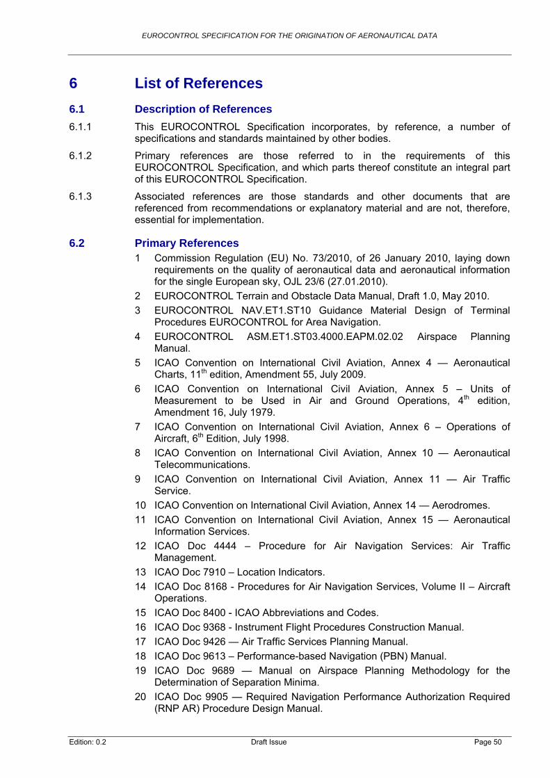
EUROCONTROL SPECIFICATION FOR THE ORIGINATION OF AERONAUTICAL DATA
6 List of References
6.1 Description of References
6.1.1 This EUROCONTROL Specification incorporates, by reference, a number of specifications and standards maintained by other bodies.
6.1.2 Primary references are those referred to in the requirements of this EUROCONTROL Specification, and which parts thereof constitute an integral part of this EUROCONTROL Specification.
6.1.3 Associated references are those standards and other documents that are referenced from recommendations or explanatory material and are not, therefore, essential for implementation.
6.2 Primary References 1 Commission Regulation (EU) No. 73/2010, of 26 January 2010, laying down
requirements on the quality of aeronautical data and aeronautical information for the single European sky, OJL 23/6 (27.01.2010).
2 EUROCONTROL Terrain and Obstacle Data Manual, Draft 1.0, May 2010.
3 EUROCONTROL NAV.ET1.ST10 Guidance Material Design of Terminal Procedures EUROCONTROL for Area Navigation.
4 EUROCONTROL ASM.ET1.ST03.4000.EAPM.02.02 Airspace Planning Manual.
5 ICAO Convention on International Civil Aviation, Annex 4 — Aeronautical Charts, 11th edition, Amendment 55, July 2009.
6 ICAO Convention on International Civil Aviation, Annex 5 – Units of Measurement to be Used in Air and Ground Operations, 4th edition, Amendment 16, July 1979.
7 ICAO Convention on International Civil Aviation, Annex 6 – Operations of Aircraft, 6th Edition, July 1998.
8 ICAO Convention on International Civil Aviation, Annex 10 — Aeronautical Telecommunications.
9 ICAO Convention on International Civil Aviation, Annex 11 — Air Traffic Service.
10 ICAO Convention on International Civil Aviation, Annex 14 — Aerodromes.
11 ICAO Convention on International Civil Aviation, Annex 15 — Aeronautical Information Services.
12 ICAO Doc 4444 – Procedure for Air Navigation Services: Air Traffic Management.
13 ICAO Doc 7910 – Location Indicators.
14 ICAO Doc 8168 - Procedures for Air Navigation Services, Volume II – Aircraft Operations.
15 ICAO Doc 8400 - ICAO Abbreviations and Codes.
16 ICAO Doc 9368 - Instrument Flight Procedures Construction Manual.
17 ICAO Doc 9426 — Air Traffic Services Planning Manual.
18 ICAO Doc 9613 – Performance-based Navigation (PBN) Manual.
19 ICAO Doc 9689 — Manual on Airspace Planning Methodology for the Determination of Separation Minima.
20 ICAO Doc 9905 — Required Navigation Performance Authorization Required (RNP AR) Procedure Design Manual.
Edition: 0.2 Draft Issue Page 50

EUROCONTROL SPECIFICATION FOR THE ORIGINATION OF AERONAUTICAL DATA
21 ICAO Circular 120 - Methodology for the Derivation of Separation Minima Applied to the Spacing between Parallel Tracks in ATS Route Structures.
22 ISO 19111:2007 — Geographic information -- Spatial referencing by coordinates.
23 ISO 19114:2003 — Geographic information -- Quality evaluation procedures.
24 ISO 19115:2003 — Geographic information – Metadata.
6.3 Associated References 25 Directive 2007/2/EC of the European Parliament and of the Council of
14 March 2007 establishing an Infrastructure for Spatial Information in the European Community (INSPIRE).
26 EUROCAE ED-99/DO-272 “User Requirements for Aerodrome Mapping Information”.
27 EUROCAE ED-119A - Interchange Standards for Terrain, Obstacle, and Aerodrome Mapping Data.
28 EUROCONTROL AIX Specification.
29 EUROCONTROL Data Assurance Level Specification.
30 EUROCONTROL Data Quality Requirements Specification.
31 EUROCONTROL Flight Inspection of RNAV Procedures.
32 EUROCONTROL Validation of RNAV Procedures.
33 ICAO Doc 8071 – Manual on Testing of Radio Navigation Aids.
34 ICAO Doc 8126 – Aeronautical Information Services Manual, Sixth Edition, 2003.
35 ICAO Doc 8697 – Aeronautical Chart Manual, Second Edition, 1987.
36 ICAO Doc 9674 - World Geodetic System — 1984 (WGS-84) Manual.
37 ICAO Doc 9689 _ Manual on Airspace Planning Methodology for the Determination of Separation Minima.
38 ICAO Doc 9906 – The Quality Assurance Manual for Flight Procedure Design.
39 ICAO Doc 9881 - Guidelines for Electronic Terrain, Obstacle and Aerodrome Mapping Information.
40 Joint Committee for Guides in Metrology (JCGM9 100:2008 Evaluation of measurement data — Guide to the expression of uncertainty in measurement (GUM1995 with minor corrections).
41 National Imaging and Mapping Agency TR8350.2 - Department of Defense, World Geodetic System 1984, 3rd Edition, Amendment 1, 2000.
Edition: 0.2 Draft Issue Page 51

EUROCONTROL SPECIFICATION FOR THE ORIGINATION OF AERONAUTICAL DATA
Annex A CONFIGURATION CONTROL
A.1 MoC ELEMENT IDENTIFICATION
MoC_Name MoC_ID MoC_Edition
EUROCONTROL Specification for the Origination of Aeronautical Data
EUROCONTROL-SPEC-xxxx 1.0
A.2 MoC ELEMENT CHANGE RECORD
A.2.1 The following table records the complete history of the successive editions of MoC specifications.
Specification Document Identifier
Edition Number
Edition Date Reason for
Change Sections Affected
EUROCONTROL-SPEC-xxxx 1.0 xx/xx/xx
Initial specification
All
A.3 MoC ELEMENT TRACEABILITY TOWARDS REGULATORY PROVISIONS
A.3.1 The following table records the traceability history of regulatory provisions associated with this MoC element.
Specification Document Identifier
Edition Number
Implementing Rule References
References of Regulatory Provisions
Validation Date
EUROCONTROL-SPEC-xxxx 1.0
Commission Regulation (EU) 73/2010
Article 6(4), (5) and (6)
Edition: 0.2 Draft Issue Page 52

EUROCONTROL SPECIFICATION FOR THE ORIGINATION OF AERONAUTICAL DATA
Annex B Conformity Material
This section specifies the conformity assessment material available for the MoC specified in this EUROCONTROL Specification, in Chapter 2.
Applicants claiming conformance to this EUROCONTROL Specification should complete the Conformance Statement below.
Note: In the following table, compliance is indicated in the “Req” column as “M” (Mandatory), “O” (Optional) or “CM” (Conditional and Mandatory) or “CO” (Conditional and Optional).
Identifier Feature Req Dependency
DO-DQR-010 Data quality requirements. M
DO-REF-010 Horizontal reference system. M
DO-REF-020 Application of ITRF transformation – different ITRF version.
M
DO-REF-030 Dynamic terrestrial reference frame.
M
DO-REF-040 Version of horizontal reference frame.
M
DO-REF-050 Recording of horizontal reference frame and co-ordinates.
M
DO-REF-060 Height relative to Mean Sea Level. M
DO-REF-070 Geoid model to determine MSL reference surface.
M
DO-REF-080 Geoid model other than EGM-96 to be ISO 19111 compliant.
M
DO-REF-090 Geoid undulation to be transformed to WGS-84 for non-global geoid model not based on WGS-84.
M
DO-REF-100 Geoid model for elevations relative to MSL.
M
DO-REF-110 Recording of information about geoid model.
M
DO-REF-120 Recording of originator of model for geoid model other than EGM-96.
M
DO-REF-130 Temporal reference system. M
DO-UOM-010 Units of measurements in M
Edition: 0.2 Draft Issue Page 53

EUROCONTROL SPECIFICATION FOR THE ORIGINATION OF AERONAUTICAL DATA
Edition: 0.2 Draft Issue Page 54
Identifier Feature Req Dependency
accordance with Annex 5.
DO-UOM-020 Recording of unit of measurement as metadata.
M
DO-UOM-030 Positions – sexagesimal degrees and resolution to meet data quality requirements.
M
DO-UOM-040 Bearings, azimuths, magnetic variations – decimal degrees and resolution to meet data quality requirements.
M
DO-UOM-050 Units for dimensions and distances. M
DO-UOM-060 Primary unit – distances. M
DO-UOM-070 Alternative primary unit – distances. O
DO-UOM-080 Primary unit for elevations, altitudes and heights.
M
DO-UOM-090 Alternative primary unit for elevations, altitudes and heights.
O
DO-UOM-100 Units for calculated and derived vertical references.
M
DO-DSS-010 Common data set specification. M
DO-DSS-020 Documentation of data set specification.
M
DO-DPS-010 Use of Data Product Specification by requesting party.
M
DO-DPS-020 Content of Data Product Specification.
M
DO-DPS-030 Data originator - compliance with Data Product Specification.
M
DO-DPS-040 Independent verification of data. M
DO-DPS-050 Data originator – production of report.
M
DO-DPS-060 Requesting party – verification of implementation of Data Product Specification.
M
DO-CAT-010 Determination of magnetic O

EUROCONTROL SPECIFICATION FOR THE ORIGINATION OF AERONAUTICAL DATA
Edition: 0.2 Draft Issue Page 55
Identifier Feature Req Dependency
variation.
DO-CAT-020 Provision of date of measurement and annual rate of change.
O
DO-CAT-030 Provision of station declination. M
DO-CAT-040 Calculation or derivation of data not determined by survey.
M
DO-CAT-050 Method of calculation or derivation. M
DO-CAT-060 Quality of input data. M
DO-CAT-070 Conversion of distances and angular units.
M
DO-CAT-080 Determination of distance and length data.
M
DO-CAT-090 Geodesic distances for distance and length.
M
DO-CAT-100 Calculation of bearing data. M
DO-CAT-110 Determination / calculation of elevation/height/altitude data.
M
DO-CAT-120 Validation of derived data. M
DO-CAT-130 Recording of method of validation. M
DO-CAT-140 Provision of GNSS service area co-ordinates.
M
DO-CAT-150 Co-ordinates and extent of Prohibited, Restricted and Danger Areas.
M
DO-CAT-160 Allocation of identifier for Prohibited, Restricted and Danger Areas.
M
DO-CAT-170 Identification of radio navigation aids.
M
DO-CAT-180 Identification of special navigation systems.
M
DO-CAT-190 Identification of GNSS. M
DO-CAT-200 Identification of significant points. M
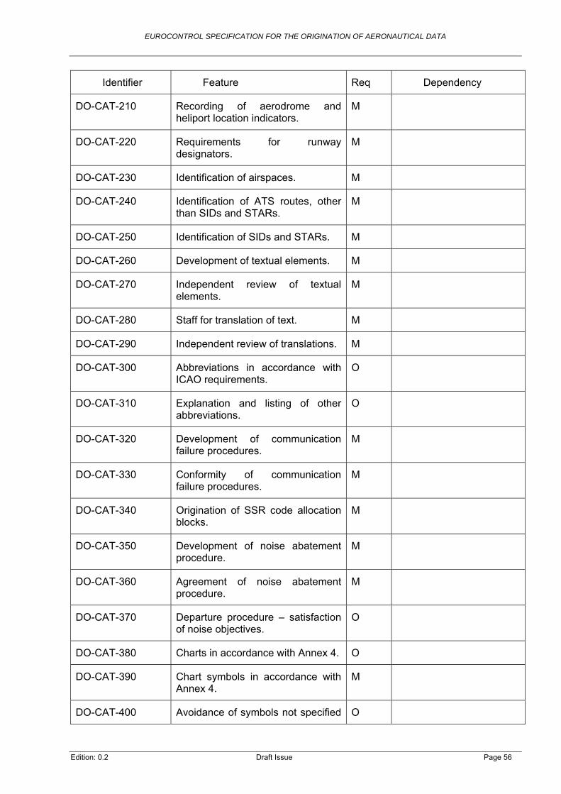
EUROCONTROL SPECIFICATION FOR THE ORIGINATION OF AERONAUTICAL DATA
Edition: 0.2 Draft Issue Page 56
Identifier Feature Req Dependency
DO-CAT-210 Recording of aerodrome and heliport location indicators.
M
DO-CAT-220 Requirements for runway designators.
M
DO-CAT-230 Identification of airspaces. M
DO-CAT-240 Identification of ATS routes, other than SIDs and STARs.
M
DO-CAT-250 Identification of SIDs and STARs. M
DO-CAT-260 Development of textual elements. M
DO-CAT-270 Independent review of textual elements.
M
DO-CAT-280 Staff for translation of text. M
DO-CAT-290 Independent review of translations. M
DO-CAT-300 Abbreviations in accordance with ICAO requirements.
O
DO-CAT-310 Explanation and listing of other abbreviations.
O
DO-CAT-320 Development of communication failure procedures.
M
DO-CAT-330 Conformity of communication failure procedures.
M
DO-CAT-340 Origination of SSR code allocation blocks.
M
DO-CAT-350 Development of noise abatement procedure.
M
DO-CAT-360 Agreement of noise abatement procedure.
M
DO-CAT-370 Departure procedure – satisfaction of noise objectives.
O
DO-CAT-380 Charts in accordance with Annex 4. O
DO-CAT-390 Chart symbols in accordance with Annex 4.
M
DO-CAT-400 Avoidance of symbols not specified O

EUROCONTROL SPECIFICATION FOR THE ORIGINATION OF AERONAUTICAL DATA
Edition: 0.2 Draft Issue Page 57
Identifier Feature Req Dependency
in Annex 4.
DO-CAT-410 New symbols – consideration of human factors and existing symbols.
M
DO-CAT-420 Assessment of new symbols. M
DO-CAT-430 Explanation of meaning of new symbols.
M
DO-CAT-440 Marking of withdrawn data. M
DO-PRO-010 Processing of data/information. M
DO-EXC-010 Exchange of data by direct electronic transmission.
M
DO-EXC-020 Agreement of data exchange format.
O
DO-EXC-030 Compliance of data exchange format.
O
DO-EXC-040 Documentation of means and format for data exchange.
M
DO-EXC-050 Compliance of formal arrangements.
M
DO-QUA-010 Quality assurance. M
DO-TSW-010 Function of software and tools. M
DO-TSW-020 No conformity assessment by manufacturer - User responsibilities before use.
M
DO-TSW-030 Independent checking using manual computation.
M
DO-TSW-040 Independent survey for verification of software.
O
DO-TSW-050 Accuracy and reliability of control survey.
CM DO-TSW-040
DO-VAL-010 Data validation and verification. M
DO-VAL-020 Validation and verification of data prior to use in deriving / calculating data.
M

EUROCONTROL SPECIFICATION FOR THE ORIGINATION OF AERONAUTICAL DATA
Edition: 0.2 Draft Issue Page 58
Identifier Feature Req Dependency
DO-SVY-010 Spatial accuracy. O
DO-SVY-020 Survey method for origination capable of meeting data quality requirements.
M
DO-SVY-030 Validation that survey method capable of meeting data quality requirements.
M
DO-SVY-040 Best practice. O
DO-SVY-050 Calibration and performance of survey equipment.
M
DO-SVY-060 Sensor calibration instructions. M
DO-SVY-070 Radiometric calibration of sensor system.
O
DO-SVY-080 Valid time of use for equipment calibration.
M
DO-SVY-090 Survey report content. M
DO-SVY-100 Loading of reference points. M
DO-SVY-110 Evaluation of reference points. M
DO-SVY-120 Digital capture and storage of measurements.
M
DO-SVY-130 Provision of evidence concerning gross errors – where information cannot be measured by digital sensors.
M
DO-SVY-140 Use of data model in sensor software.
O
DO-SVY-150 Maintenance period for surveyed, calculated and derived data.
M
DO-SVY-160 Digital capture and storage of observations, parameters and intermediate data.
M
DO-SVY-170 Maintenance of information and records.
M
DO-SVY-180 Availability of observations. M

EUROCONTROL SPECIFICATION FOR THE ORIGINATION OF AERONAUTICAL DATA
Edition: 0.2 Draft Issue Page 59
Identifier Feature Req Dependency
DO-SVY-190 Monitoring of critical and essential data.
M
DO-SVY-200 Monitoring of routine data. O
DO-SVY-210 Periodic review of difference between ITRF version required and that used.
M
DO-SVY-220 Resurvey where positional accuracy exceeds accuracy requirement.
M
DO-SVY-230 Determination of frequency for complete re-survey.
M
DO-SVY-240 Conversion process requirements for conversion to ITRF.
M
DO-SVY-250 Survey accuracies. M
DO-SVY-260 Additional observations to increase reliability of measurement.
O
DO-SVY-270 Reliability of origination of co-ordinate data.
M
DO-SVY-280 Survey observations to include resolution and accuracy of equipment.
O
DO-SVY-290 Additional measurement for critical data.
M
DO-SVY-300 Independence of additional measurements.
O
DO-SVY-310 Evidence for transformation to and from local co-ordinate system.
M
DO-SVY-320 Use of UTM for planar co-ordinate system.
O
DO-SVY-330 Recording of projection parameters for planar co-ordinate system.
CM DO-SVY-320
DO-SVY-340 Recording of additional observations.
O
DO-SVY-350 Contacts for clarification of facilities. M
DO-SVY-360 Use of geodetic control network. M

EUROCONTROL SPECIFICATION FOR THE ORIGINATION OF AERONAUTICAL DATA
Edition: 0.2 Draft Issue Page 60
Identifier Feature Req Dependency
DO-SVY-370 Establishment of survey control stations network where no geodetic network or inappropriate geodetic network.
M
DO-SVY-380 Minimum number of survey control stations.
O
DO-SVY-390 Location of survey control stations. O
DO-SVY-400 Process requirements for survey control stations.
M
DO-SVY-410 Data quality requirements for survey control stations.
M
DO-SVY-420 Internal precision for survey control network.
M
DO-SVY-430 Distance requirements between survey control stations and items to be surveyed.
M
DO-SVY-440 Monitoring of position of survey control stations.
M
DO-SVY-450 Resurvey of relevant data where changes in position of survey control stations.
M
DO-SVY-460 Validation of survey control stations.
O
DO-SVY-470 Re-measurement of survey control station’s position.
M
DO-SVY-480 Monumentation for survey control stations.
M
DO-SVY-490 Type of survey control station monumentation.
M
DO-SVY-500 Investigation prior to installation of survey control station.
O
DO-SVY-510 Requirements for monumentation where fewer than recommended number of survey control stations.
O
DO-SVY-520 Unique identifier for survey control station.
M
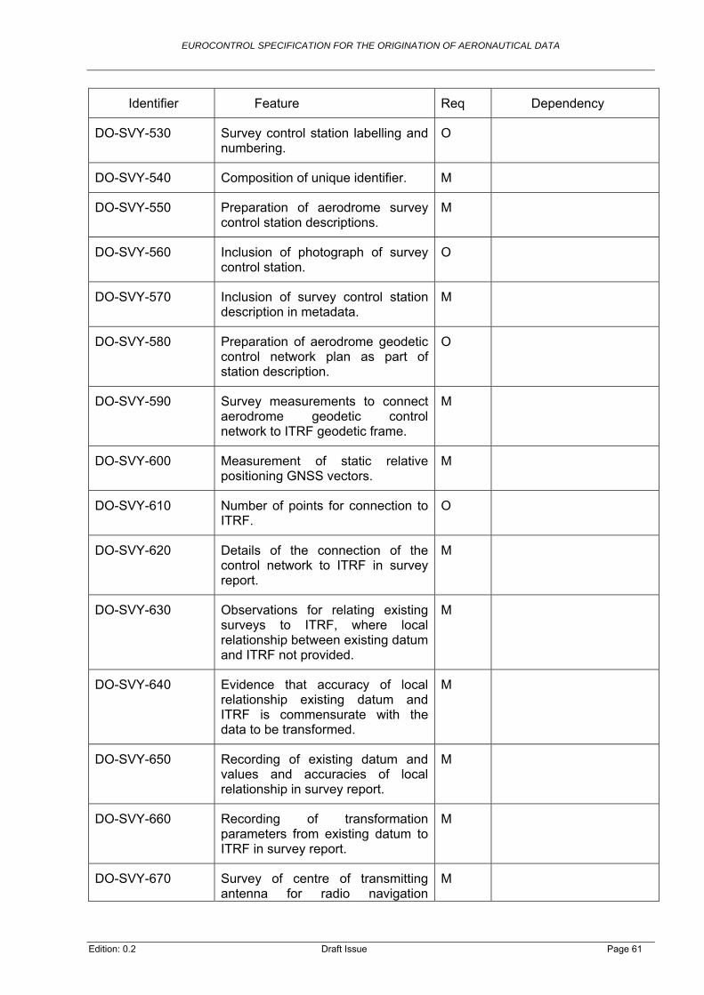
EUROCONTROL SPECIFICATION FOR THE ORIGINATION OF AERONAUTICAL DATA
Edition: 0.2 Draft Issue Page 61
Identifier Feature Req Dependency
DO-SVY-530 Survey control station labelling and numbering.
O
DO-SVY-540 Composition of unique identifier. M
DO-SVY-550 Preparation of aerodrome survey control station descriptions.
M
DO-SVY-560 Inclusion of photograph of survey control station.
O
DO-SVY-570 Inclusion of survey control station description in metadata.
M
DO-SVY-580 Preparation of aerodrome geodetic control network plan as part of station description.
O
DO-SVY-590 Survey measurements to connect aerodrome geodetic control network to ITRF geodetic frame.
M
DO-SVY-600 Measurement of static relative positioning GNSS vectors.
M
DO-SVY-610 Number of points for connection to ITRF.
O
DO-SVY-620 Details of the connection of the control network to ITRF in survey report.
M
DO-SVY-630 Observations for relating existing surveys to ITRF, where local relationship between existing datum and ITRF not provided.
M
DO-SVY-640 Evidence that accuracy of local relationship existing datum and ITRF is commensurate with the data to be transformed.
M
DO-SVY-650 Recording of existing datum and values and accuracies of local relationship in survey report.
M
DO-SVY-660 Recording of transformation parameters from existing datum to ITRF in survey report.
M
DO-SVY-670 Survey of centre of transmitting antenna for radio navigation
M
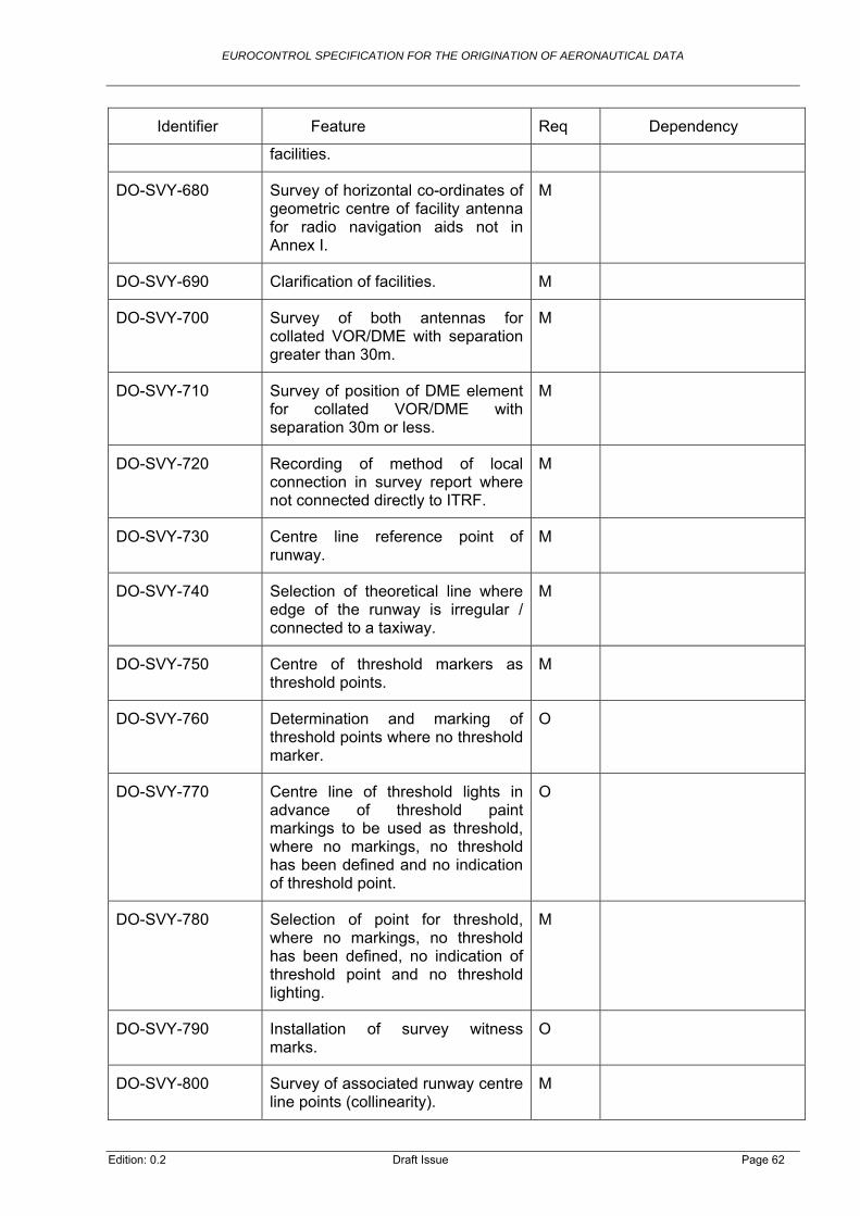
EUROCONTROL SPECIFICATION FOR THE ORIGINATION OF AERONAUTICAL DATA
Edition: 0.2 Draft Issue Page 62
Identifier Feature Req Dependency
facilities.
DO-SVY-680 Survey of horizontal co-ordinates of geometric centre of facility antenna for radio navigation aids not in Annex I.
M
DO-SVY-690 Clarification of facilities. M
DO-SVY-700 Survey of both antennas for collated VOR/DME with separation greater than 30m.
M
DO-SVY-710 Survey of position of DME element for collated VOR/DME with separation 30m or less.
M
DO-SVY-720 Recording of method of local connection in survey report where not connected directly to ITRF.
M
DO-SVY-730 Centre line reference point of runway.
M
DO-SVY-740 Selection of theoretical line where edge of the runway is irregular / connected to a taxiway.
M
DO-SVY-750 Centre of threshold markers as threshold points.
M
DO-SVY-760 Determination and marking of threshold points where no threshold marker.
O
DO-SVY-770 Centre line of threshold lights in advance of threshold paint markings to be used as threshold, where no markings, no threshold has been defined and no indication of threshold point.
O
DO-SVY-780 Selection of point for threshold, where no markings, no threshold has been defined, no indication of threshold point and no threshold lighting.
M
DO-SVY-790 Installation of survey witness marks.
O
DO-SVY-800 Survey of associated runway centre line points (collinearity).
M

EUROCONTROL SPECIFICATION FOR THE ORIGINATION OF AERONAUTICAL DATA
Edition: 0.2 Draft Issue Page 63
Identifier Feature Req Dependency
DO-SVY-810 Use of collinearity testing to verify the accuracy of runway threshold co-ordinates.
M
DO-SVY-820 Survey of two thresholds and two runway centre line points for runway with threshold at both ends.
O
DO-SVY-830 Features to be surveyed on runway that is not straight.
O
DO-SVY-840 Collinearity testing of four points. CO DO-SVY-820
DO-SVY-850 Angular deviation between vectors – straight runways.
M
DO-SVY-860 Full independent survey if collinearity testing fails or runway not straight.
M
DO-SVY-870 Determination of distance from surveyed threshold point to end of paved surface.
M
DO-SVY-880 Determination of longitudinal slope. M
DO-SVY-890 Longitudinal slope, point spacing. M
DO-SVY-900 Calculation parameters for the calculation of slope of TODA – where clearway declared.
M
DO-SVY-920 Measurement of TORA, ASDA, TODA and LDA.
O
DO-SVY-930 Measurement of distances along runway centre line and of any stopway and clearway.
CM DO-SVY-920
DO-SVY-940 Adjustment of end of TORA, ASDA and LDA to provide runway end safety area.
O
DO-SVY-950 Determination of threshold co-ordinates where point for survey is not coincident with runway threshold.
M
DO-SVY-960 Collinearity check for derived threshold co-ordinates.
M
DO-SVY-970 Centre of taxiway centre line marking, apron taxiline marking or
M
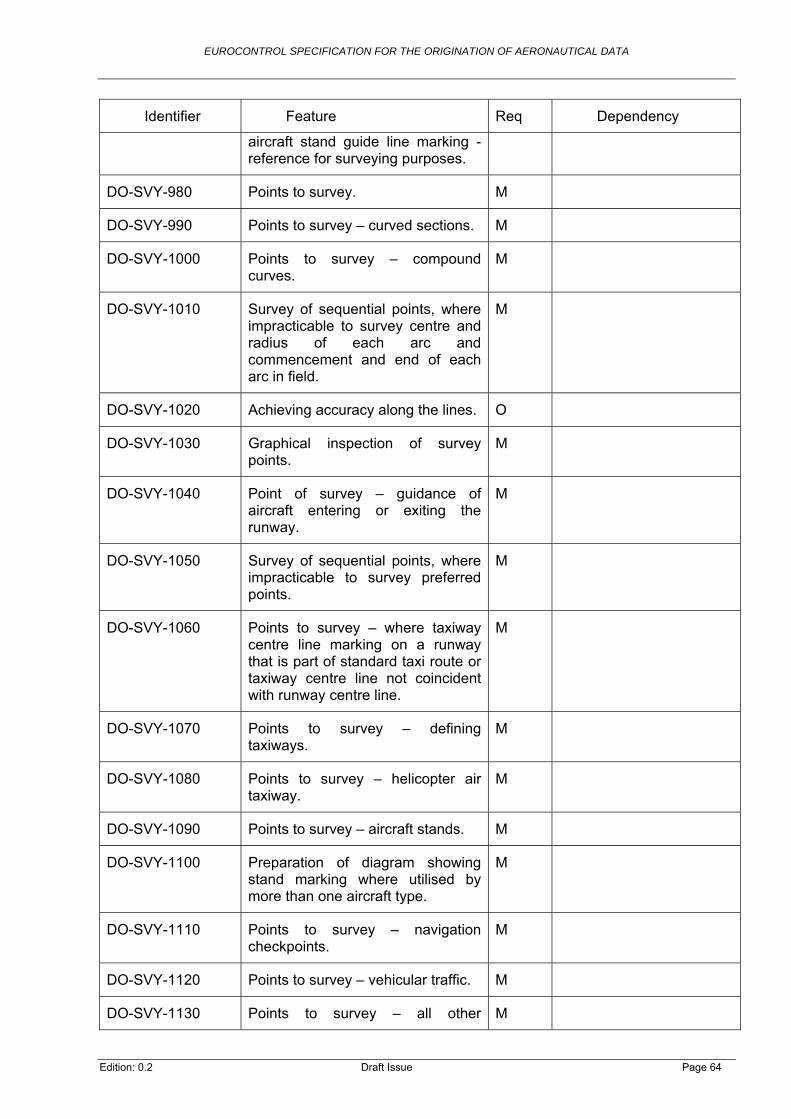
EUROCONTROL SPECIFICATION FOR THE ORIGINATION OF AERONAUTICAL DATA
Edition: 0.2 Draft Issue Page 64
Identifier Feature Req Dependency
aircraft stand guide line marking - reference for surveying purposes.
DO-SVY-980 Points to survey. M
DO-SVY-990 Points to survey – curved sections. M
DO-SVY-1000 Points to survey – compound curves.
M
DO-SVY-1010 Survey of sequential points, where impracticable to survey centre and radius of each arc and commencement and end of each arc in field.
M
DO-SVY-1020 Achieving accuracy along the lines. O
DO-SVY-1030 Graphical inspection of survey points.
M
DO-SVY-1040 Point of survey – guidance of aircraft entering or exiting the runway.
M
DO-SVY-1050 Survey of sequential points, where impracticable to survey preferred points.
M
DO-SVY-1060 Points to survey – where taxiway centre line marking on a runway that is part of standard taxi route or taxiway centre line not coincident with runway centre line.
M
DO-SVY-1070 Points to survey – defining taxiways.
M
DO-SVY-1080 Points to survey – helicopter air taxiway.
M
DO-SVY-1090 Points to survey – aircraft stands. M
DO-SVY-1100 Preparation of diagram showing stand marking where utilised by more than one aircraft type.
M
DO-SVY-1110 Points to survey – navigation checkpoints.
M
DO-SVY-1120 Points to survey – vehicular traffic. M
DO-SVY-1130 Points to survey – all other M
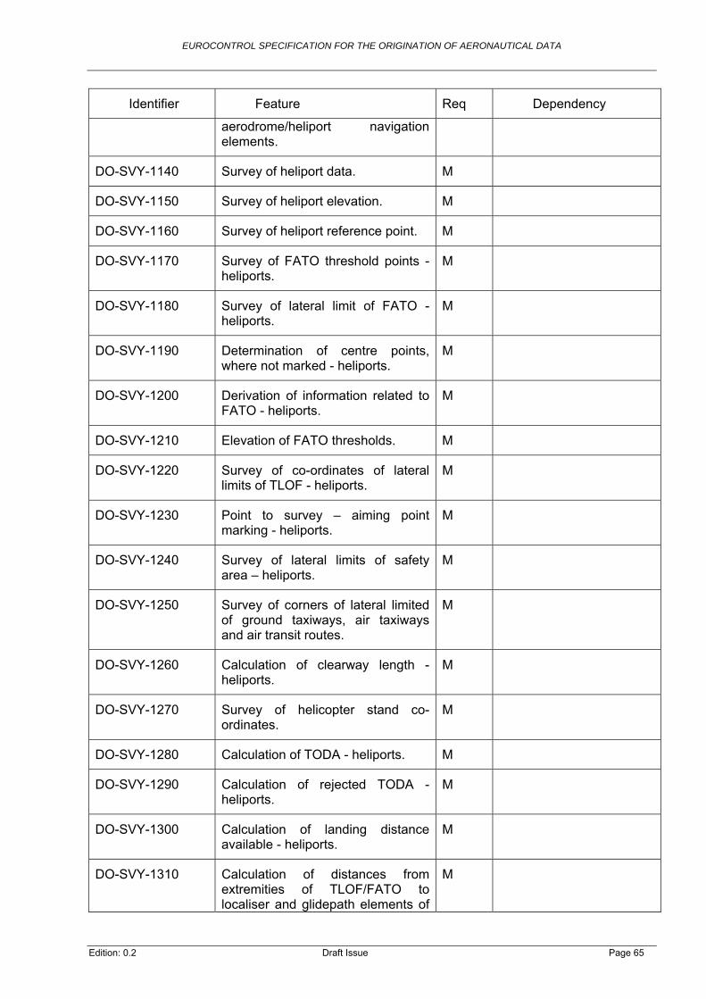
EUROCONTROL SPECIFICATION FOR THE ORIGINATION OF AERONAUTICAL DATA
Req Dependency Identifier Feature
aerodrome/heliport navigation elements.
DO-SVY-1140 Survey of heliport data. M
DO-SVY-1150 Survey of heliport elevation. M
DO-SVY-1160 Survey of heliport reference point. M
DO-SVY-1170 Survey of FATO threshold points - heliports.
M
DO-SVY-1180 Survey of lateral limit of FATO - heliports.
M
DO-SVY-1190 Determination of centre points, where not marked - heliports.
M
DO-SVY-1200 Derivation of information related to FATO - heliports.
M
DO-SVY-1210 Elevation of FATO thresholds. M
DO-SVY-1220 Survey of co-ordinates of lateral limits of TLOF - heliports.
M
DO-SVY-1230 Point to survey – aiming point marking - heliports.
M
DO-SVY-1240 Survey of lateral limits of safety area – heliports.
M
DO-SVY-1250 Survey of corners of lateral limited of ground taxiways, air taxiways and air transit routes.
M
DO-SVY-1260 Calculation of clearway length - heliports.
M
DO-SVY-1270 Survey of helicopter stand co-ordinates.
M
DO-SVY-1280 Calculation of TODA - heliports. M
DO-SVY-1290 Calculation of rejected TODA - heliports.
M
DO-SVY-1300 Calculation of landing distance available - heliports.
M
DO-SVY-1310 Calculation of distances from extremities of TLOF/FATO to localiser and glidepath elements of
M
Edition: 0.2 Draft Issue Page 65

EUROCONTROL SPECIFICATION FOR THE ORIGINATION OF AERONAUTICAL DATA
Req Dependency Identifier Feature
ILS – heliports.
DO-SVY-1320 Calculation of distances from extremities of TLOF/FATO to azimuth and elevation antenna of MLS – heliports.
M
DO-SVY-1330 Origination of obstacle data. M
DO-SVY-1340 Origination of terrain data. M
DO-SVY-1350 Transfer of control station and reference point information.
M
DO-SVY-1360 Transfer and loading of raw data. M
DO-SVY-1370 Recording of parameters used in data processing.
M
DO-SVY-1380 Validation of parameters used in data processing.
M
DO-SVY-1390 Treatment of intermediate data. M
DO-SVY-1400 Validation of intermediate data. M
DO-SVY-1410 Recording of association between raw data, parameters and intermediate data.
M
DO-SVY-1420 Verification of geometry of features derived by human interaction with base data.
M
DO-SVY-1430 Identification of and reporting of any deviation from data quality requirements or unknown conformance of data.
M
DO-SVY-1440 Evaluation of data. M
DO-SVY-1450 Processing and provision of data to allow its quality to be evaluated.
M
DO-SVY-1460 Reporting of results of data quality evaluation.
M
DO-SVY-1470 Reporting of quantative quality results.
M
DO-SVY-1480 Determination of conformance with quality level.
M
Edition: 0.2 Draft Issue Page 66
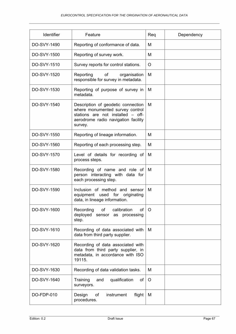
EUROCONTROL SPECIFICATION FOR THE ORIGINATION OF AERONAUTICAL DATA
Req Dependency Identifier Feature
DO-SVY-1490 Reporting of conformance of data. M
DO-SVY-1500 Reporting of survey work. M
DO-SVY-1510 Survey reports for control stations. O
DO-SVY-1520 Reporting of organisation responsible for survey in metadata.
M
DO-SVY-1530 Reporting of purpose of survey in metadata.
M
DO-SVY-1540 Description of geodetic connection where monumented survey control stations are not installed – off-aerodrome radio navigation facility survey.
M
DO-SVY-1550 Reporting of lineage information. M
DO-SVY-1560 Reporting of each processing step. M
DO-SVY-1570 Level of details for recording of process steps.
M
DO-SVY-1580 Recording of name and role of person interacting with data for each processing step.
M
DO-SVY-1590 Inclusion of method and sensor equipment used for originating data, in lineage information.
M
DO-SVY-1600 Recording of calibration of deployed sensor as processing step.
O
DO-SVY-1610 Recording of data associated with data from third party supplier.
M
DO-SVY-1620 Recording of data associated with data from third party supplier, in metadata, in accordance with ISO 19115.
DO-SVY-1630 Recording of data validation tasks. M
DO-SVY-1640 Training and qualification of surveyors.
O
DO-FDP-010 Design of instrument flight procedures.
M
Edition: 0.2 Draft Issue Page 67

EUROCONTROL SPECIFICATION FOR THE ORIGINATION OF AERONAUTICAL DATA
Req Dependency Identifier Feature
DO-FDP-020 Recording of analysis, results and conclusions where divergence from appropriate guidance material.
M
DO-FDP-030 Election of national design criteria. M
DO-FDP-040 Justification, documentation and safety case for national design criteria.
M
DO-FDP-050 Guidance for designing PBN routes and procedures.
O
DO-FDP-060 Protection of runways by obstacle limitation surfaces.
M
DO-FDP-070 Documentation of data sources. M
DO-FDP-080 Validation of data by designer when no formal arrangement with data supplier.
M
DO-FDP-090 Application of additional lateral and vertical buffers where level of accuracy for terrain and obstacle data not guaranteed.
M
DO-FDP-100 Conduct of flight validation where level of accuracy for terrain and obstacle data not guaranteed.
M
DO-FDP-110 Electronic data transfer and storage.
M
DO-FDP-120 Verification checks for manual data entry.
M
DO-FDP-130 Co-ordination with stakeholders during design phase.
M
DO-FDP-140 Formal links with data service providers.
O
DO-FDP-150 Training and qualification of instrument flight procedure designers.
M
DO-FDP-160 Specialist PBN courses. M
DO-FDP-170 Validation of instrument flight procedure.
M
Edition: 0.2 Draft Issue Page 68

EUROCONTROL SPECIFICATION FOR THE ORIGINATION OF AERONAUTICAL DATA
Req Dependency Identifier Feature
DO-FDP-180 Validation and verification of instrument flight procedure design.
M
DO-FDP-190 Scope of validation and verification process.
O
DO-FDP-200 Recording of results of validation and verification in metadata.
O
DO-FDP-210 Validation and checking of PBN procedures for flyability.
DO-FDP-220 Validation of navaid coverage and performance assumptions by flight inspection.
O
DO-FDP-230 Scope of flight inspection. O
DO-FDP-240 When flight checks may be used.
DO-FDP-250 Traceability of instrument flight procedures.
M
DO-FDP-260 Scope of information to be recorded on source of production of instrument flight procedures.
M
DO-FDP-270 Maintenance of records for instrument flight procedures.
M
DO-ASD-010 Criteria for airspace design. M
DO-ASD-020 Design of ATS routes. M
DO-ASD-030 Recording of analysis, results and conclusions where divergence from appropriate guidance material.
M
DO-ASD-040 Application of national criteria. M
DO-ASD-050 Notification of application of national criteria.
M
DO-ASD-060 Documentation of justification for applying national criteria and modified criteria.
M
DO-ASD-070 Justification, documentation and safety case for national criteria.
M
DO-ASD-080 Use of guidelines. O
Edition: 0.2 Draft Issue Page 69
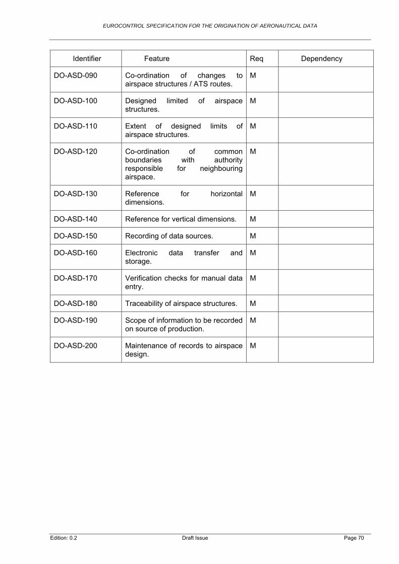
EUROCONTROL SPECIFICATION FOR THE ORIGINATION OF AERONAUTICAL DATA
Req Dependency Identifier Feature
DO-ASD-090 Co-ordination of changes to airspace structures / ATS routes.
M
DO-ASD-100 Designed limited of airspace structures.
M
DO-ASD-110 Extent of designed limits of airspace structures.
M
DO-ASD-120 Co-ordination of common boundaries with authority responsible for neighbouring airspace.
M
DO-ASD-130 Reference for horizontal dimensions.
M
DO-ASD-140 Reference for vertical dimensions. M
DO-ASD-150 Recording of data sources. M
DO-ASD-160 Electronic data transfer and storage.
M
DO-ASD-170 Verification checks for manual data entry.
M
DO-ASD-180 Traceability of airspace structures. M
DO-ASD-190 Scope of information to be recorded on source of production.
M
DO-ASD-200 Maintenance of records to airspace design.
M
Edition: 0.2 Draft Issue Page 70

EUROCONTROL SPECIFICATION FOR THE ORIGINATION OF AERONAUTICAL DATA
Edition: 0.2 Draft Issue Page 71
Annex C Traceability to Regulatory Provisions
C.1 Traceability Between Regulatory Provisions and EUROCONTROL Specification for the Origination of Aeronautical Data
C.1.1 Introduction
C.1.1.1 This Appendix provides traceability from regulatory provisions, in particular, from the Articles and Annexes of Commission Regulation (EU) 73/2010, to the detailed technical provisions of the EUROCONTROL Specification for the Origination of Aeronautical Data. Commission Regulation (EU) 73/2010 makes extensive references to ICAO Annex 15 requirements, so traceability is also provided to the relevant Annex 15 requirements.
C.1.2 Articles in Commission Regulation (EU) 73/2010
C.1.2.1 Relevant Articles of Commission Regulation (EU) 73/2010 are reproduced in the first two columns of the table below, followed by a cross-reference to the corresponding paragraph in this EUROCONTROL Specification, together with explanatory notes.
Article 6. Data quality
Reg Ref.
Regulation Text EUROCONTROL Specification ref.
Notes
Article 6(4)
When acting as data originators, the parties referred to in Article 2(2), shall comply with the data origination requirements laid down in Annex IV, Part D.
2.2.2.1, 2.2.2.2, 2.2.5.2, 2.2.10, 2.3.2, 2.3.3, 2.3.4, 2.3.6 , 2.3.7
Article 6(5)
Aeronautical information service providers shall ensure that aeronautical data and aeronautical information provided by data originators not referred to in Article 2(2) are made available to the next intended user with sufficient quality to meet the intended use.
2.2.1, 2.2.4, 2.2.10
Article 6(6)
When acting as the entity responsible for the official request for a data origination activity, the parties referred to in Article 2(2) shall ensure that:
(a) the data are created, modified or deleted in compliance with their instructions 2.2.4
(b) without prejudice to Annex IV, Part C, their data origination instructions contain, as a minimum
(i) an unambiguous description of the data that are to be created, modified or deleted
2.2.4

EUROCONTROL SPECIFICATION FOR THE ORIGINATION OF AERONAUTICAL DATA
Reg Ref.
Regulation Text EUROCONTROL Specification ref.
Notes
(ii) confirmation of the entity to which the data are to be provided 2.2.4
(iii) the date and time by which the data are to be provided 2.2.4
(iv) the data origination report format to be used by the data originator
2.2.4
Annex IV
Reg Ref. Regulation Text EUROCONTROL Specification ref.
Notes
Part D 1. The surveying of radio navigation aids and the origination of calculated or derived data whose coordinates are published in the AIP shall be carried out in accordance with appropriate standards and at least in accordance with the relevant ICAO provisions referred to in point 20 of Annex III.
2.2.5.2, 2.3.6
2. All surveyed data shall be referenced to WGS-84 as specified in the ICAO provisions referred to in point 2 of Annex III 2.2.2.1
3. A geoid model, sufficient to meet the ICAO provisions referred to in point 3 of Annex III and the aeronautical data and aeronautical information quality requirements laid down in Annex IV, shall be used in order that all vertical data (surveyed, calculated or derived) may be expressed relative to mean sea level via the Earth Gravitational Model 1996. A ‘geoid’ means the equipotential surface in the gravity field of the Earth, which coincides with the undisturbed mean sea level extended continuously through the continents.
2.2.2.2
4. Surveyed, calculated and derived data shall be maintained throughout the lifetime of each data item.
2.3.3
5. Survey data categorised as critical or essential data shall be subject to a full initial survey, and thereafter shall be monitored for changes on a yearly basis, as a minimum. Where changes are detected, re-survey of the relevant data shall be undertaken.
2.3.3
6. The following electronic survey data capture and storage techniques shall be employed:
(a) reference point coordinates shall be loaded to the surveying equipment by digital data transfer;
2.3.2
(b) the measurements in the field shall be stored digitally; 2.3.2
Edition: 0.2 Draft Issue Page 72

EUROCONTROL SPECIFICATION FOR THE ORIGINATION OF AERONAUTICAL DATA
Reg Ref. Regulation Text EUROCONTROL Specification ref.
Notes
(c) raw data shall be digitally transferred and loaded into the processing software.
2.3.7
7. All survey data categorised as critical data shall be subject to sufficient additional measurement to identify survey errors not detectable by single measurement.
2.3.4
8. Aeronautical data and aeronautical information shall be validated and verified prior to use in deriving or calculating other data.
2.2.5.2, 2.2.10
Edition: 0.2 Draft Issue Page 73
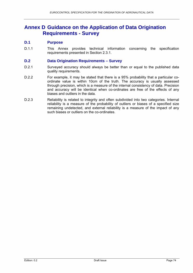
EUROCONTROL SPECIFICATION FOR THE ORIGINATION OF AERONAUTICAL DATA
Edition: 0.2 Draft Issue Page 74
Annex D Guidance on the Application of Data Origination Requirements - Survey
D.1 Purpose
D.1.1 This Annex provides technical information concerning the specification requirements presented in Section 2.3.1.
D.2 Data Origination Requirements – Survey
D.2.1 Surveyed accuracy should always be better than or equal to the published data quality requirements.
D.2.2 For example, it may be stated that there is a 95% probability that a particular co-ordinate value is within 10cm of the truth. The accuracy is usually assessed through precision, which is a measure of the internal consistency of data. Precision and accuracy will be identical when co-ordinates are free of the effects of any biases and outliers in the data.
D.2.3 Reliability is related to integrity and often subdivided into two categories. Internal reliability is a measure of the probability of outliers or biases of a specified size remaining undetected, and external reliability is a measure of the impact of any such biases or outliers on the co-ordinates.

EUROCONTROL SPECIFICATION FOR THE ORIGINATION OF AERONAUTICAL DATA
Annex E Guidance on the Application of Data Origination Requirements – Procedure Design
E.1 Purpose
E.1.1 This Annex provides technical information concerning the specification requirements presented in section 2.4.
E.2 Data Origination Requirements – Procedure Design
E.2.1 The values of the data elements are usually published as integers. Where this does not provide the required accuracy, the data is published with the required number of decimal places. Where the data item directly affects the flight crew in its control of the aircraft, it is normally rounded as a multiple of five.
E.2.2 In order to ensure the required accuracy, only the final results of computations should be rounded. Intermediate calculations should use the maximum resolution available.
E.3 Data Origination Requirements – Final Approach Segment (FAS) Data Block
E.3.1 The requirements for the Final Approach Segment (FAS) Data Block are detailed in the table below:
Edition: 0.2 Draft Issue Page 75

EUROCONTROL SPECIFICATION FOR THE ORIGINATION OF AERONAUTICAL DATA
Edition: 0.2 Draft Issue Page 76
Annex F Horizontal Reference Systems
F.1 Introduction
F.1.1 In section 2.2.2.1 of this EUROCONTROL Specification, the requirements on the use of the horizontal reference system for the spatial definition of aeronautical information are provided. This section provides additional information and definitions which should help in the implementation of the correct reference system.
Note: The geodetic descriptions given here are considered to be sufficient for aviation purposes. They are not intended as definitive geodetic statements.
F.2 Definitions
F.2.1 Geodetic Reference System
F.2.1.1 A reference system provides a definition of a co-ordinate system in terms of the position of an origin in space, the orientation of an orthogonal set of Cartesian axes, and a scale. A terrestrial reference system defines a spatial reference system in which positions of points anchored on the Earth’s solid surface have co-ordinates. Examples: WGS-84, ITRS/European Terrestrial Reference System (ETRS) and national reference systems.
F.2.2 Geodetic Reference Frame
F.2.2.1 A reference frame is a realisation of a reference system through a consistent set of three-dimensional station co-ordinates, taking into account the continental drifts. Examples: ITRF89 ITRF97, ITRF2000, ITRF2005. Due to plate tectonics and tidal deformation, the co-ordinates for a point change between the different ITRF realisations. The realisations are also referred to as versions.
F.2.3 WGS-84
F.2.3.1 WGS-84 defines inter alia a Conventional Terrestrial Reference System, a reference frame and a reference ellipsoid28. The system was developed by the United States Department of Defence, together with scientists of other countries and institutions. WGS-84 is currently the reference system ICAO requires for georeferencing aeronautical information.
F.2.3.2 Definition of the WGS-84 Reference System
F.2.3.2.1. The WGS-84 Co-ordinate System is a right-handed, Earth-fixed orthogonal co-ordinate system. In the National Imaging and Mapping Agency TR8350.2 - Department of Defense, WGS-84, [Reference 41], the WGS-84 is characterised as following:
a) It is geocentric, the centre of mass being defined for the whole Earth, including oceans and atmosphere;
b) Its scale is that of the local Earth frame, in the sense of a relativistic theory of gravitation;
c) Its orientation was initially given by the Bureau International de l’Heure (BIH) orientation of 1984.0;
28 More information can be found here: http://earth-info.nga.mil/GandG/publications/tr8350.2/tr8350_2.html.

EUROCONTROL SPECIFICATION FOR THE ORIGINATION OF AERONAUTICAL DATA
Edition: 0.2 Draft Issue Page 77
d) Its time evolution in orientation will create no residual global rotation with regards to the crust.
F.2.3.3 WGS-84 as a Reference Frame
F.2.3.3.1. The set of definitions for WGS-84 not only includes a reference system, but also the practical realisation of a reference frame through a set of station co-ordinates. The latest available frame is called ‘WGS-84 (G873)’, where the letter ‘G’ indicates that the station co-ordinates has been derived by Global Positioning System (GPS) techniques and the number following the ‘G’ indicates the GPS week number in which these co-ordinates were implemented (January 29, 1997). The accuracy of the station co-ordinates is in the order of 5 cm (1).
F.2.3.4 Geometric Constants of the WGS-84 Ellipsoid
F.2.3.4.1. Part of the WGS-84 definition is the ellipsoid as a geometric (mathematical) reference surface. Geometric constants of the WGS-84 ellipsoid should be as described in Table 2 and Table 3.
Semi-major axis a = 6378137.000 m
Reciprocal of Flattening f = 1/298.257223563
Angular Velocity of the earth = 7292115.0 x 10-11 rad/s
Gravitational Constant GM = (3986004.418 ± 0.008) x 108 m3/s2
Table 2: Geometric Constants
Semi-minor axis b = 6356752.3142 m
First eccentricity e = 8.1819190842622 x 10⁻²
(First eccentricity)2 e2= 6.69437999014 x 10⁻³
Mean Radius of Semi-Axes R1 = 6371008.7714 m
Table 3: Some of WGS-84 Ellipsoid Derived Geometric Constants
F.2.4 The International Terrestrial Reference System (ITRS)
F.2.4.1 Like WGS-84, the ITRS is a horizontal reference system. The ITRS is maintained by the International Earth Rotation and Reference Systems Service (IERS) and the realisation of the ITRS is the ITRF29.
F.2.4.2 Plate tectonic movement has been incorporated in this co-ordinate system using results of recent measurements and a global geophysical model. Thus, it is a model with changing co-ordinates due to the movements of the tectonic plates on which the ground stations are located. However, this reference system provides the fundamental position of the Earth to within 10 cm and the orientation of the axes to correspondingly high accuracies. Since 1988, the IERS has defined the mean spin axis, the IERS Reference Pole (IRP), the zero meridian and the IERS Reference Meridian (IRM).
29 The main web source for information related to ITRS/ITRF is: http://itrf.ensg.ign.fr/.

EUROCONTROL SPECIFICATION FOR THE ORIGINATION OF AERONAUTICAL DATA
F.2.4.3 Whilst WGS-84 is a static model, the maintenance of a dynamic datum with a higher level of accuracy, like ITRS, requires constant monitoring of the rotation of the Earth, the motion of the pole and the movement of the plates of the crust of the Earth, on which the ground stations are located. Where WGS-84 is strictly speaking defined by only 13 reference stations globally, ITRS is built up on a network of many reference stations. The continuous measurement from these stations is used to determine the dynamic variables of the ITRS.
F.2.5 International Terrestrial Reference Frame (ITRF)
F.2.5.1 The ITRF is an accurate geodetic reference frame that consists of a globally distributed network of survey stations whose positions and velocities are determined by several independent measurement technologies. Positions and velocities are published periodically by the IERS, and each published set is identified by the epoch of the station positions. Thus, the published position of a point in ITRF97 is valid at the epoch 1st January 1997, whereas the position of the point at some future time must take into account the effect of the point’s velocity. The ITRF identifies, inter alia, changes resulting from earth tectonic plate movements, so it is important that a survey record includes the epoch number for the ITRF used. The continental drift can be as much as 10cm per year (Australia), resulting in differences between co-ordinates of a point expressed in ITRF96 in relation to a point expressed in ITRF2006 of 97cm (see Table 4). In the table the co-ordinates and annual change rates (in italic) of different sites are provided in the ITRF96 and ITRF 2006 frame and the 3D distance between the two co-ordinates. For the stations Padova and Ankara the co-ordinates are also provided in the corresponding ETRF96/2005 realisations. The 3D distance in ETRF is much smaller compared to ITRF since the two station are part of the definition for the ETRF, i.e. ETRF is shifted compared to ITRF because of the movement of the European plate. Ankara being located at the border of the European Plate is impacted by a plate rotation and therefore has a large shift in ETRF than Padova.
Edition: 0.2 Draft Issue Page 78

EUROCONTROL SPECIFICATION FOR THE ORIGINATION OF AERONAUTICAL DATA
Edition: 0.2 Draft Issue Page 79
Co-ordinates expressed in ITRF96
frame Co-ordinates expressed in
ITRF2005 frame
Station Positions and velocities at
Epoch 1996/01/01 Station Positions and velocities at
Epoch 2010/01/01
Site Name Country X/Vx Y/Vy Z/Vz X/Vx Y/Vy Z/Vz 3D-
Distance
m-m/y m-m/y m-m/y m-m/y m-m/y m-m/y
Padova IT 4389531.313 923253.634 4519256.328 4389531.06 923253.874 4519256.495 0.39 cm
-0.014 0.0166 0.0121 -0.0172 0.0177 0.0113
ETRF96/05 4389531.452 923253.559 4519256.194 4389531.444 923253.543 4519256.219 0.03 cm
Ankara TR 4121934.348 2652190.008 4069035.119 4121934.467 2652190.361 4069035.4 0.47 cm
-0.0072 -0.0023 0.0077 0.0143 0.0331 0.0227
ETRF96/05 4121934.44 2652190.065 4069035.016 4121934.598 2652189.89 4069035.024 0.24 cm
Urumqi CN 228310.768 4631922.915 4367064.059 228310.313 4631922.746 4367064.046 0.49 cm
-0.0268 -0.0045 0.0056 -0.0315 -0.0037 0.0047
Yarragadee AU -2389025.489 5043316.869 -3078530.788 -2389026.153 5043317.006 -3078530.083 0.98 cm
-0.0498 0.0056 0.0491 -0.0476 0.0094 0.0499
Algonquin CA 918129.293 -4346071.292 4561977.878 918129.525 -4346071.229 4561977.818 0.25 cm
-0.0157 -0.0036 0.0038 -0.0157 -0.0023 0.0003
Santiago CL 1769693.643 -5044574.175 -3468320.869 1769693.317 -5044574.138 -3468321.069 0.38 cm
0.0239 -0.0039 0.0125 0.0219 -0.0074 0.007
Hartebeesthoek ZA 5085442.778 2668263.737 -2768696.79 5085442.779 2668263.464 -2768697.05 0.38 cm
-0.0019 0.019 0.0167 0.0007 0.0192 0.0164
Reykjavik IS 2587384.206 -1043033.536 5716564.055 2587384.523 -1043033.492 5716563.965 0.33 cm
-0.0216 -0.0028 0.0059 -0.022 -0.0039 0.0096
Table 4: Continental Drift Expressed in Different ITRF Epochs30
30 Source http://www.iers.org. For the stations ‘Padova’ and ‘Ankara’ the corresponding ETRF co-ordinates are shown too. It is obvious that the movement of the European plate is reflected in ETRF and the co-ordinates of these two stations do not differ as much in ETRF compared to ITRF.

EUROCONTROL SPECIFICATION FOR THE ORIGINATION OF AERONAUTICAL DATA
F.2.5.2 The ITRF uses the same system parameters as WGS-84. Therefore, for practical terms in aviation (navigation as well as data provision), the two frames can be regarded as identical.
F.2.6 European Terrestrial Reference System 1989 (ETRS89)
F.2.6.1 ETRS89 is a reference system defined by the Sub-commission of EUREF of the International Association for Geodesy in 1989. The system is derived from ITRS and therefore closely linked to ITRS; it uses the same ellipsoid (Geodetic Reference System (GRS) 1980), the same fundamental point and scale. The spatial orientation has been chosen in such a way that the system follows the movement of the Euro-Asian tectonic plate. Therefore, the co-ordinate of a point in central and northern Europe remains stable within the ETRS89 (internally consistent).
F.2.6.2 The ETRS89 is the base (because it is dynamic) for many national “modern” terrestrial reference systems. Modern (national or continental) reference systems distinguish themselves by a precisely defined link to the global system, allowing absolute positioning with centimetre-accuracy for any point in time, from its establishment. This can be achieved through a complex modelling of the relationship, based on epochs and velocities (i.e. the amount of drift between the two systems).
F.2.7 European Terrestrial Reference Frame (ETRF)
F.2.7.1 ETRF is a precise geodetic reference frame established by a number of survey stations throughout Europe whose relative positions are known to the accuracy in the order of 2-3 cm. For the realisation of ETRS (ETRF89…ETRF2000), the positions of the ITRS stations in and around Europe, at the beginning of 1989, were used as a reference. Only stations on the stable part of the Eurasian plate were used as these are considered to be consistent. Co-ordinates of the stations used for the realisation are the same in ITRF89 and ETRF89.
F.2.7.2 Due to the continental-drift of the Eurasian plate, ITRF2000 and ETRF89 co-ordinates differed by about 25 cm in the year 2000, a difference which is increasing by about 2.5 cm per year.
F.2.7.3 More than 200 stations forming the EUREF Permanent Network publish their GNSS data freely over the internet which allows the co-ordinate of any location within Europe to be easily determined with centimetre accuracy.
F.2.8 Relationship Between WGS-84, ITRF and ETRF
F.2.8.1 The theoretical principles of WGS-84, ITRS and ETRS89 systems are the same. For WGS-84, the position of the reference ellipsoid was initially calculated on the basis of available data and modelled as a best-fit for the whole world but with limited precision (initially with 1-2 metres, the latest models with 5 cm). ITRS 2000 is practically identical to the latest instantiation of WGS-84.
F.2.8.2 ETRF89 was identical to ITRF at the 1989 epoch. ETRF is only used in Europe but the relationship between ITRF and ETRF is well known and transformation parameters are available for the various epochs.
F.2.8.3 The reference network for WGS-84 consists of only 12 stations around the world, whereas the EUREF Permanent Network (EPN) consists of over 200 stations within Europe. In practical terms, this means that GNSS surveys within Europe are most easily realised if they are based on ETRS89, and subsequently converted to the appropriate epoch of ITRS, presently ITRS 2000.
Edition: 0.2 Draft Issue Page 80

EUROCONTROL SPECIFICATION FOR THE ORIGINATION OF AERONAUTICAL DATA
Edition: 0.2 Draft Issue Page 81
F.3 Recommendations
F.3.1 Determining Position in the ITRF
F.3.1.1 There are two options for fixing a survey station to the current ITRF, namely direction and indirect connection.
1) For the direct connection to ITRF method:
In this method the surveyor establishes a direct connection between an ITRF station and the new point, using a GNSS technique. The GNSS data from a permanent reference network site with ITRF co-ordinates and velocities are used in conjunction with GNSS data acquired at the required point by the surveyor. The two data sets are processed in a geodetic application to determine the co-ordinate of the required point. This option enables direct connection to the ITRF in a relatively simple and established way. The parameters and the length of the data acquisition should be chosen carefully depending on the base line length. Whenever possible, more than one reference station in ITRF should be used to ensure that the connection to the reference frame is robust in terms of redundancy.
2) For the indirect connection through regional reference frame and transformation method:
In order to avoid the difficulty associated with long base lines, determination the co-ordinates of the required point may be determined by measurements relatively to a reference station, in a regional reference frame such as ETRF. The survey procedure is the same as in for direct connection. Once the co-ordinates are known in the regional reference frame, they should be transformed to ITRF using the available transformation parameters. The user should ensure that the proper epoch is used when selecting the transformation parameters. An alternative approach within Europe is to first establish the co-ordinates of the control station by fixing to ETRF89 using EUREF (or other suitable stations derived from the EUREF network) stations. These co-ordinates can then be transformed to ITRF using the appropriate transformation parameters (see paragraph K.3.1)31.
F.3.1.2 Whilst the differences between coordinate systems ITRF and ETRF, or ETRF89 and ETRF2000 are significant in terms of the precision required of the points, their absolute differences are small enough to prevent identification by means of the data values themselves. Therefore, it is essential that the reference frame used is identified and the surveyor should ensure that with each co-ordinate the horizontal reference frame and the epoch are stored.
F.3.2 Monitoring and Updating Co-ordinates due to the Continental Drift
F.3.2.1 Whilst the use of ETRF89 is conceptually simple and relatively easy to manage, it introduces one fundamental problem. The ETRF89 network is gradually drifting away from the ITRF at a rate of 2-3cm per year and, for some locations around the world, the drift of the tectonic plate compared with ITRF can be as large as 10cm per year. To achieve global harmonisation, ICAO requires that all co-ordinates should be published in WGS-84 which, from ICAO Annex 15 has been equated to ITRF 2000.
F.3.2.2 In the long-term, the difference between a regional reference frame and ITRF (and hence WGS-84) co-ordinates for the same point could become too great to meet
31 This method may be beneficial to a number of States since the availability of a relatively dense network of Stations as a result of the EUREF campaign simplifies the logistics involved in establishing the position of the control station.

EUROCONTROL SPECIFICATION FOR THE ORIGINATION OF AERONAUTICAL DATA
Edition: 0.2 Draft Issue Page 82
the ICAO Annex 15 requirements [Reference 11]. However, as long as all GNSS measurements are based on differential vectors between a known co-ordinate and a new position, the drift does not impact the (relative) measurement. Therefore, all co-ordinates published in any aviation data set should be referenced to ITRF 2000. Combining different versions of a reference frame within the same data set should be avoided.
F.3.2.3 When the responsible geodetic body for publishing the regional reference frame provides accurate transformation to ITRF at any epoch, the co-ordinates determined by the indirect connection method (as mentioned above) should be transformed to ITRF 2000.
F.3.2.4 Where a local geodetic control network has been established for the surveying of aeronautical features, the transformation of the geodetic control network to ITRF 2000 should be determined by resurvey. The transformation parameters should then be applied to all co-ordinates linked to at least one of the control network stations.
F.3.2.5 At least every five years, the co-ordinates of the required point should be resurveyed.
F.4 Resources
F.4.1 Free Data Services
F.4.1.1 Several sources of free GPS and reference frame data are accessible via the Internet. These can be used to gain access to the ITRF and ETRF in a relatively straightforward manner:
International GNSS Service (IGS) products (precise orbits, satellite clock models): National Aeronautics and Space Administration (NASA) website32;
EUREF GPS Receiver Independent Exchange Format (RINEX) data: EUREF website33;
ETRS to ITRS transformations: EUREF website ; 34
International Earth Rotation Service (IERS) products: IERS website35;
Crustal Dynamics Data Information Service (CDDIS): CDDIS (NASA) 36
F.4.2.1 stems, networks and techniques:
website .
F.4.2 Other Useful Websites
Resources for information on reference sy
EUREF Permanent network site37;
32 http://igscb.jpl.nasa.gov correct on 05/07/07. 33 http://www.epncb.oma.be/_dataproducts/datacentres/index.php correct on 05/07/07. 34 http://www.epncb.oma.be/_trackingnetwork/coordinates/stationcoordinates.php correct on 05/07/07. 35 http://www.iers.org correct on 05/07/07. 36 http://cddisa.gsfc.nasa.gov/cddis.html correct on 05/07/07. 37 http://www.epncb.oma.be correct on 05/07/07.

EUROCONTROL SPECIFICATION FOR THE ORIGINATION OF AERONAUTICAL DATA
Edition: 0.2 Draft Issue Page 83
GPS time and date converter (useful as part of the on-line data acquisition service), available on the Scripps Orbit and Permanent Array Center
neral information on GPS
ority (European Geostationary Navigation Overlay Service (EGNOS), GALILEO) website40;
Federal Space Agency Russia, Information-Analytical Centre GLONASS provider) website41.
(SOPAC) website38;
US Coastguard Navigation Centre website (gestatus and development)39;
European GNSS Supervisory Auth
38 http://sopac.ucsd.edu/scripts/convertDate.cgi correct on 05/07/07. 39 http://www.navcen.uscg.gov/gps/default.htm correct on 05/07/07. 40 http://www.gs.europa.eu checked September 09. 41 http://www.glonass-ianc.rsa.ru checked September 09.

EUROCONTROL SPECIFICATION FOR THE ORIGINATION OF AERONAUTICAL DATA
Edition: 0.2 Draft Issue Page 84
Annex G Vertical Reference Systems
G.1 Definitions
G.1.1 Vertical Reference System
G.1.1.1 A vertical (height) reference system can be defined by only two parameters: A point with a known elevation from which vertical differences are calculated, and the reference surface. The different height systems are briefly explained below.
G.1.2 Ellipsoidal Heights
G.1.2.1 The ellipsoid, which is used as part of the definition of a geodetic datum, can be used as a reference surface. The Ellipsoidal Height is the orthogonal distance between a point and the reference ellipsoid. Therefore, it does not take into account the Earth’s gravity field.
G.1.3 Orthometric Heights
G.1.3.1 The Orthometric Height is the distance (H) along a line of force from a given point (P) on the physical surface of the earth to the geoid (the line is perpendicular to the equipotential surfaces at different levels).
G.1.4 Normal Heights
G.1.4.1 The Normal Height (H*) of a point is computed from its geopotential difference to that of sea level. It takes into account the normal gravity, computed along the plumb line of the point (height difference of a point to the quasi-geoid). The difference between the Normal Height and the Ellipsoidal Height is called height-anomaly or quasi-geoid-height.
G.1.5 Geoid – Earth Gravitational Model (EGM)
G.1.5.1 The geoid is the equipotential surface of the earth’s gravity field, chosen at a certain level (approximately MSL) which serves as the reference surface for height measurements. Globally, the difference in elevation between the geoid and the geocentric ellipsoid is between ± 100m.
G.1.5.2 Global and local geoids differ in their origin: global geoids consider only the long- and middle-wave part of the earth’s gravity field, whilst local geoids also consider the short-wave part of the gravity field. Global geoids are used when consistent orthometric heights, over long distances (continent or earth surveying), are required. Currently, the world’s best global geoid model is the EGM 200842. It was determined using satellite tracking, gravity anomalies and satellite altimetry. Its accuracy is in the range of ± 0.05 m (oceans) and ± 0.5 m (on land). This accuracy is higher in flat regions than in topographically mountainous terrain, such as the Alps.
G.1.5.3 For local engineering applications and cadastre-surveying, global geoids are not as accurate as needed. For such applications, local geoid models are calculated. These can only be developed using local field measurements. They offer centimetre accuracy over several hundred kilometres, with a high resolution. Local
42 http://earth-info.nga.mil/GandG/WGS-84/gravitymod/egm2008/index.html.

EUROCONTROL SPECIFICATION FOR THE ORIGINATION OF AERONAUTICAL DATA
Edition: 0.2 Draft Issue Page 85
geoids are not suitable for height comparison over large distances since they are based on different origins and reference heights (different equipotential levels).
Terrain surfaceGeoid
Ellipsoid surfa
ce
Ellipsoidal height (H)
point
Geoid undulation (N)
Terrain surfaceGeoid
Ellipsoid surfa
ce
Ellipsoidal height (H)
point
Geoid undulation (N)
Figure 2: Geoid Undulations with Respect to an Ellipsoid
G.1.6 European Vertical Reference System
G.1.6.1 The European Vertical Reference System (EVRS) has been built to reflect the globalisation of GIS applications and the need for continental-wide, consistent height information. EVRS is a gravity-related height reference system, i.e. the height values provided are Normal Heights. The EVRS is a tidal zero system. The EVRS is realised in the European Vertical Reference Frame (EVRF) by the geopotential numbers and Normal Heights of nodal points of the United European Levelling Network 95/98 extended for Estonia, Latvia, Lithuania and Romania, in relation to the Normaal Amsterdams Peils (NAP). The geopotential number at NAP is zero.
G.2 Recommendations for Determining Heights Relative to EGM-96
G.2.1 Introduction
G.2.1.1 The ICAO SARPs mandate that all height information should be published relative to MSL (orthometric heights). To determine the geoid undulation, EGM-96 should be used but may be replaced by a more accurate geoid model where the accuracy of EGM-96 is not sufficient.
G.2.1.2 The most stringent accuracy requirements covered by the standards are geoid undulations for several on-aerodrome facilities. These accuracy requirements are 0.25m (95% confidence interval) for both measurements. This can be readily achieved for computing ellipsoidal heights using appropriate GNSS equipment. However, achieving these accuracy requirements for geoid undulations is more difficult at the present time. Recommended methodologies for determining the geoid undulations are provided below.
G.2.1.3 Because the elevation values of a point may not differ significantly between Ellipsoidal height, EGM-96 height or any other vertical reference system height the surveyor should ensure that with each elevation value, the vertical reference frame is stored.

EUROCONTROL SPECIFICATION FOR THE ORIGINATION OF AERONAUTICAL DATA
G.2.2 Method 1
G.2.2.1 When a new feature is surveyed using GNSS means, the primary reference frame for the determination of a co-ordinate is the ellipsoid. It is common that GNSS sensors (or their processing software) have an EGM-96 integrated, therefore allowing the direct determination of height above MSL (in EGM-96). When a new survey point is determined by GNSS, the elevation above EGM-96 should be directly determined.
G.2.2.2 If neither the sensor nor the GNSS processing software have the capability to integrate the EGM-96 undulation for a surveyed point, the ellipsoidal height should be stored for the required point. The geoid undulation should then be determined by interpolation from EGM-96 for the given latitude and longitude of the point.
G.2.2.3 The same method may also be used for an airborne data acquisition method when the position of the sensor platform is determined by GNSS.
G.2.3 Method 2
G.2.3.1 A national geodetic body may have scientifically determined a geoid. Provided this geoid is of sufficient accuracy and is referenced to a horizontal reference frame which allows transformation to WGS-84/ITRF without a loss of accuracy, then, for given values of the latitude and longitude of a point, the geoid undulation should be interpolated directly from the data.
G.2.3.2 The geoid model used should be published by the ANSP to allow a transformation to EGM-96 or any other vertical reference frame.
G.2.4 Method 3
G.2.4.1 If a national / regional levelling system is free from limiting systematic biases, and the offset between the national tide gauge datum and the geoid is known (h), then geoid undulations should be computed by measuring the height of a point above the levelling datum (h) and the ellipsoid (H). The geoid undulation at that point is then given by the relationship:
N = H – h + Δh
G.2.4.2 A realistic estimate of the quality of the heighting network should be obtained from the relevant authorities prior to carrying out the survey work. The accuracy of the heighting network should be documented, together with the data set as metadata.
G.2.4.3 The method should only be used when the benchmark values are known with sufficient accuracy.
G.2.5 Deriving Elevation Information from Existing Sources
G.2.5.1 Some of the elevation information does not have very stringent quality requirements (DME, minimum altitudes). In many regions, Digital Terrain Models (DTM) exist which may be used for deriving the elevation information. The accuracy of the DTM should be at least 1.5 times higher than the data quality requirement of the required feature. The resolution of the DTM should be adequate for the topography to ensure that the highest elevation of the real world is maintained in the digital data set.
G.2.5.2 The DTM should be available in the same horizontal reference system as the required feature.
G.2.5.3 For linear or polygonal features, the elevation information should be derived by determining the highest value within the area of interest. For point features, the
Edition: 0.2 Draft Issue Page 86

EUROCONTROL SPECIFICATION FOR THE ORIGINATION OF AERONAUTICAL DATA
Edition: 0.2 Draft Issue Page 87
potential horizontal displacement between the two data sets should be taken into account.
G.3 Resources
G.3.1 Useful Websites
The NASA Goddard Space Flight Center (GSFC) and National Imagery and Mapping Agency (NIMA) Joint Geopotential Model EGM9643;
The EGM 200844;
EVRS website45.
43 http://cddis.nasa.gov/926/egm96. 44 http://earth-info.nga.mil/GandG/wgs84/gravitymod/egm2008. 45 http://www.bkg.bund.de/geodIS/EVRS.

EUROCONTROL SPECIFICATION FOR THE ORIGINATION OF AERONAUTICAL DATA
Annex H Monumentation
H.1 Monumentation Types - General
H.1.1 Where survey markers are installed, they should be of a type appropriate to the task, and to the surface and ground beneath it.
H.1.2 Designs of suggested survey markers are shown in this section, but other appropriate types of marker may be used.
H.1.3 Survey markers should be durable (robust) and locally stable so that their position does not change over seasons or years.
H.1.4 Survey markers should be secured against accidental destruction by self-evident marking.
Edition: 0.2 Draft Issue Page 88
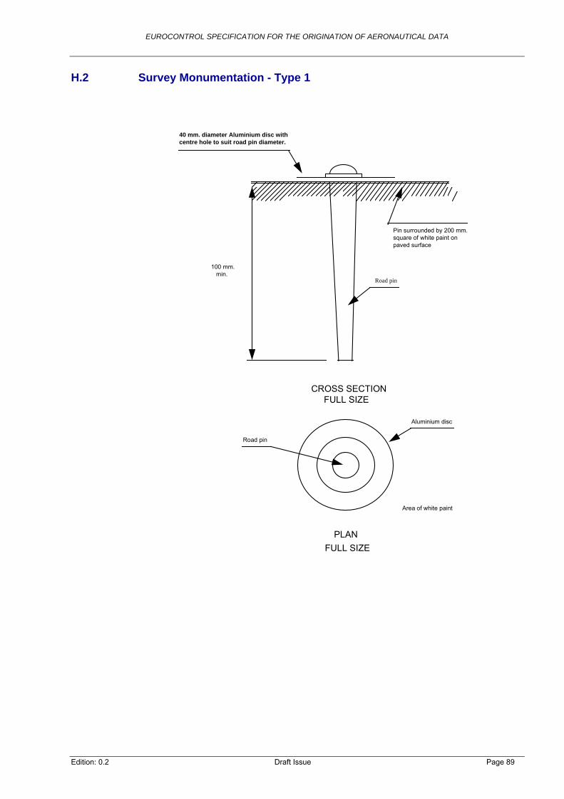
EUROCONTROL SPECIFICATION FOR THE ORIGINATION OF AERONAUTICAL DATA
Edition: 0.2 Draft Issue Page 89
H.2 Survey Monumentation - Type 1
40 mm. diameter Aluminium disc withcentre hole to suit road pin diameter.
Pin surrounded by 200 mm.square of white paint onpaved surface
Road pin
100 mm. min.
CROSS SECTION FULL SIZE
Aluminium disc
Road pin
PLAN
FULL SIZE
Area of white paint

EUROCONTROL SPECIFICATION FOR THE ORIGINATION OF AERONAUTICAL DATA
H.3 Survey Monumentation - Type 2
SV coverBevelled top withcentre punchnail at top
Concrete500x500 mmon plan
Compressiblefiller 25 mmthick minimum
20 mm diameterstainless steelrod 600 mm. long.
trial pitback filledwith concrete
10 mm. diameter stainless steelrod 100 mm. long fitted throughpre-drilled hole in 20 mm. dia (vertical) rod.
Edition: 0.2 Draft Issue Page 90
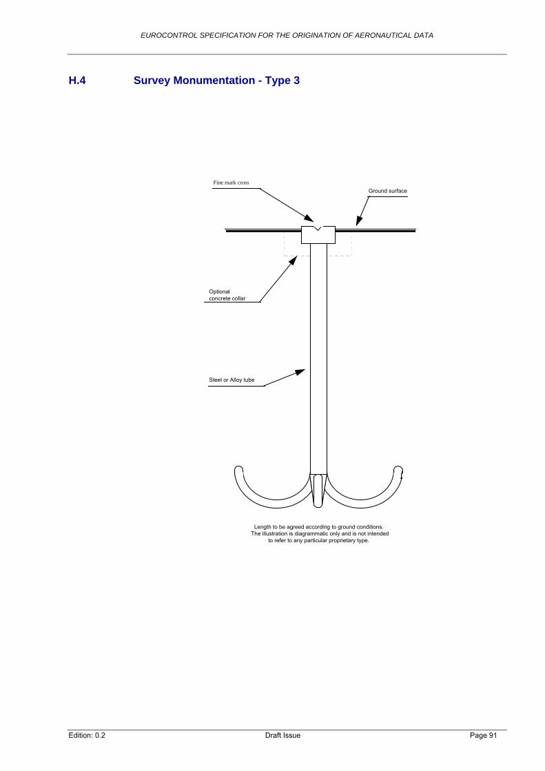
EUROCONTROL SPECIFICATION FOR THE ORIGINATION OF AERONAUTICAL DATA
Edition: 0.2 Draft Issue Page 91
H.4 Survey Monumentation - Type 3
Steel or Alloy tube
Optional concrete collar
Fine mark crossGround surface
Length to be agreed according to ground conditions.The illustration is diagrammatic only and is not intended to refer to any particular proprietary type.

EUROCONTROL SPECIFICATION FOR THE ORIGINATION OF AERONAUTICAL DATA
H.5 Example Numbering System for Survey Markers
H.5.1 Each survey control point which forms part of the aerodrome survey control network should be marked in the field with a unique identification number.
H.5.2 The system of numbering should include the ICAO aerodrome identifier and the station identifier.
Note: Although the aerodrome identifier will be the same for each station at that aerodrome, and, therefore serve no local purpose, its inclusion is important for identification purposes in digital databases.
H.5.3 Station identifiers, whether they are alphabetic or numeric, should be assigned chronologically upon the construction of the station.
H.5.4 Whilst numbering systems will vary from State to State, it is important that each system includes a means whereby the stations are not confused with other surveys which may be conducted at the aerodrome.
Note: A simple consecutive numbering system alone, without other identifiers, would not be suitable.
Edition: 0.2 Draft Issue Page 92

EUROCONTROL SPECIFICATION FOR THE ORIGINATION OF AERONAUTICAL DATA
Annex I Description of Airport Facilities
I.1 General
I.1.1 This Annex standardises the determination of threshold points and navaids for survey purposes. The illustrations contained within this Annex indicate the planimetric position of the points that should be surveyed.
Note: For guidance on survey points for runway and taxiway intersections and holding points see ICAO Doc 9674 (WGS-84 Manual) [Reference 36].
I.1.2 Where the location of the actual threshold is not known and embedded threshold lights do not exist, then the most appropriate diagram should be selected to indicate the point surveyed.
I.1.3 Where none of the diagrams included in this annex are appropriate, a new diagram should be prepared, showing the actual arrangement of markings and the point selected for survey.
I.1.4 Wing-bar threshold lights and lights installed ahead of the runway hard surface should have no direct survey status with respect to thresholds.
I.1.5 Other points than the ones mentioned on the figures may need to be surveyed as a result of specific national specifications or applicable standards. Where such requirements exist, the survey records should provide clear information about the points surveyed, for example, through the use of diagrams similar to those shown in this Annex, identifying what has been surveyed.
I.1.6 Legend
Edition: 0.2 Draft Issue Page 93

EUROCONTROL SPECIFICATION FOR THE ORIGINATION OF AERONAUTICAL DATA
I.2 Threshold Marking Example - Type 1
Note: Illustration of normative requirement DO-SVY-750 and following (“regular” threshold, precision approach runway)
Edition: 0.2 Draft Issue Page 94

EUROCONTROL SPECIFICATION FOR THE ORIGINATION OF AERONAUTICAL DATA
I.3 Threshold Marking Example - Type 2
Note: Illustration of normative requirement DO-SVY-750 and following (“regular” threshold, non-precision approach runway)
Edition: 0.2 Draft Issue Page 95

EUROCONTROL SPECIFICATION FOR THE ORIGINATION OF AERONAUTICAL DATA
I.4 Threshold Marking Example - Type 3
Note: Illustration of normative requirement DO-SVY-750 and following
Edition: 0.2 Draft Issue Page 96

EUROCONTROL SPECIFICATION FOR THE ORIGINATION OF AERONAUTICAL DATA
Threshold Marking Example - Type 4
Note: Illustration of normative DO-SVY-750 and following (displaced threshold)
Edition: 0.2 Draft Issue Page 97
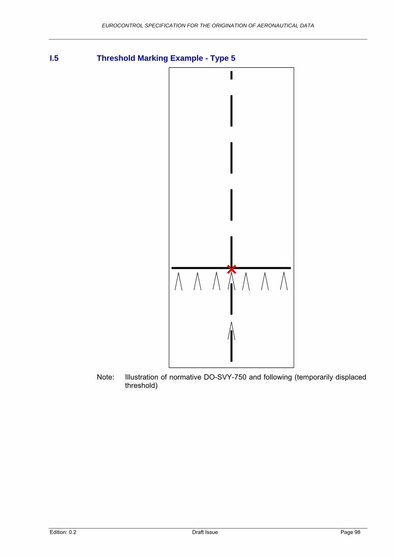
EUROCONTROL SPECIFICATION FOR THE ORIGINATION OF AERONAUTICAL DATA
I.5 Threshold Marking Example - Type 5
Note: Illustration of normative DO-SVY-750 and following (temporarily displaced threshold)
Edition: 0.2 Draft Issue Page 98
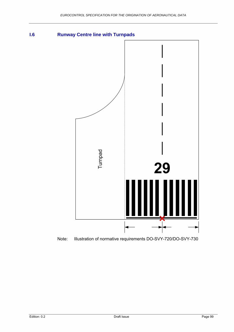
EUROCONTROL SPECIFICATION FOR THE ORIGINATION OF AERONAUTICAL DATA
I.6 Runway Centre line with Turnpads
Tur
npad
Note: Illustration of normative requirements DO-SVY-720/DO-SVY-730
Edition: 0.2 Draft Issue Page 99

EUROCONTROL SPECIFICATION FOR THE ORIGINATION OF AERONAUTICAL DATA
Edition: 0.2 Draft Issue Page 100
I.7 Intermediate Holding Positions and Stop Bars
Holding position Stop bar
Note: Illustration of normative requirement DO-SVY-1070

EUROCONTROL SPECIFICATION FOR THE ORIGINATION OF AERONAUTICAL DATA
I.8 Runway Distances
Note: Illustration of the various distances as defined in DO-SVY-920
I.9 Collinearity testing
Note: Illustration of the collinearity testing as defined in DO-SVY-840
Edition: 0.2 Draft Issue Page 101

EUROCONTROL SPECIFICATION FOR THE ORIGINATION OF AERONAUTICAL DATA
I.10 Taxiway Markings
Note: Illustration of normative requirements DO-SVY-970 ff.
Edition: 0.2 Draft Issue Page 102

EUROCONTROL SPECIFICATION FOR THE ORIGINATION OF AERONAUTICAL DATA
I.11 Taxiway on Runway Marking
Note: Illustration of normative requirement DO-SVY-1060
Edition: 0.2 Draft Issue Page 103

EUROCONTROL SPECIFICATION FOR THE ORIGINATION OF AERONAUTICAL DATA
Edition: 0.2 Draft Issue Page 104
I.12 ILS Localiser (Example)
05
Centre-Line
Survey Point
Note: Illustration of normative requirement DO-SVY-670

EUROCONTROL SPECIFICATION FOR THE ORIGINATION OF AERONAUTICAL DATA
I.13 ILS Glide Path (Example)
Survey Point
Survey Point
Note: Illustration of normative requirement DO-SVY-670
Edition: 0.2 Draft Issue Page 105

EUROCONTROL SPECIFICATION FOR THE ORIGINATION OF AERONAUTICAL DATA
I.14 MLS Azimuth (Example)
Note: Illustration of normative requirement DO-SVY-670
I.14.1 Recommendation: Reference should be made to the local authority for the survey point.
Edition: 0.2 Draft Issue Page 106

EUROCONTROL SPECIFICATION FOR THE ORIGINATION OF AERONAUTICAL DATA
Edition: 0.2 Draft Issue Page 107
I.15 MLS Glide Path (Example)
. .
. .
. .
. .
. .
. .
. .
. .
. .
Note: Illustration of normative requirement DO-SVY-670

EUROCONTROL SPECIFICATION FOR THE ORIGINATION OF AERONAUTICAL DATA
I.16 VOR/DME (Example)
Note: Illustration of normative requirement DO-SVY-690
Edition: 0.2 Draft Issue Page 108

EUROCONTROL SPECIFICATION FOR THE ORIGINATION OF AERONAUTICAL DATA
I.17 DVOR/DME (Example)
Note: Illustration of normative requirement DO-SVY-690
Edition: 0.2 Draft Issue Page 109

EUROCONTROL SPECIFICATION FOR THE ORIGINATION OF AERONAUTICAL DATA
I.18 TACAN (Example)
Note: Illustration of normative requirement DO-SVY-670
Edition: 0.2 Draft Issue Page 110

EUROCONTROL SPECIFICATION FOR THE ORIGINATION OF AERONAUTICAL DATA
I.19 VOR (Example)
Note: Illustration of normative requirement DO-SVY-670
Edition: 0.2 Draft Issue Page 111

EUROCONTROL SPECIFICATION FOR THE ORIGINATION OF AERONAUTICAL DATA
I.20 NDB, Locator (Example)
Note: Illustration of normative requirement DO-SVY-670
Edition: 0.2 Draft Issue Page 112

EUROCONTROL SPECIFICATION FOR THE ORIGINATION OF AERONAUTICAL DATA
Annex J Description of Heliport Facilities
J.1 Heliport Survey Points
J.1.1 The illustrations contained within this Annex indicate the planimetric position of the points that should be surveyed. It is intended to support the requirements for the survey of features at a heliport in section 2.3.6.9.
J.1.2 Where none of the diagrams included in this annex are appropriate, a new diagram should be prepared, showing the actual arrangement of markings and the point selected for survey.
J.1.3 Other points than the ones mentioned on the figures may need to be surveyed as a result of specific national specifications or applicable standards. Where such requirements exist, the survey records should provide clear information about the points surveyed, for example, through the use of diagrams similar to those shown in this Annex, identifying what has been surveyed.
J.1.4 Legend Heliport
Edition: 0.2 Draft Issue Page 113

EUROCONTROL SPECIFICATION FOR THE ORIGINATION OF AERONAUTICAL DATA
J.2 TLOF (example)
Note: Illustration of normative requirement DO-SVY-1220
Edition: 0.2 Draft Issue Page 114

EUROCONTROL SPECIFICATION FOR THE ORIGINATION OF AERONAUTICAL DATA
J.3 FATO Threshold
Note: Illustration of normative requirements DO-SVY-1180 and DO-SVY-1190
Edition: 0.2 Draft Issue Page 115
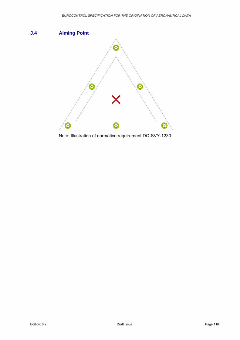
EUROCONTROL SPECIFICATION FOR THE ORIGINATION OF AERONAUTICAL DATA
J.4 Aiming Point
Note: Illustration of normative requirement DO-SVY-1230
Edition: 0.2 Draft Issue Page 116

EUROCONTROL SPECIFICATION FOR THE ORIGINATION OF AERONAUTICAL DATA
Edition: 0.2 Draft Issue Page 117
Annex K Survey Procedures
K.1 General
K.1.1 This Annex provides best practice guidance for:
The establishment of control points (Section DO-SVY-040);
GNSS based surveying of facilities (Sections 2.3.1 and DO-SVY-660);
Reference Systems used during survey;
Transformation:
Horizontal co-ordinates;
Vertical / Elevation information.
l Terrestrial Sensors;
g (ALS);
Guidance on survey techniques:
Conventiona
GNSS;
Airborne Laser Scannin
Photogrammetry.
This information is intended to supplement the requirements stated in section K.1.2 2.3 of eir interpretation.
ta Origination
K.2.1.1
he WGS-84 values derived from
K.2.1.2
K.2.1.3
for use in air navigation to support a homogeneous and consistent reference frame.
this EUROCONTROL Specification and thereby assist in th
K.2 Reference Systems used During Da
K.2.1 Reference Systems for Surveying
The relevant ICAO Annexes require that WGS-84 is used as reference system in air navigation and that, consequently, all co-ordinates are expressed in this geodetic datum. Since access to WGS-84 is difficult to realise with centimetre precision (limited number of reference stations), and because the WGS-84 co-ordinate system is aligned with ITRS, surveying in ITRF can be regarded as identical. However, in many European countries access to ETRF and elsewhere to a local (dynamic) geodetic reference frame is much simpler than access to ITRF (i.e. shorter base lines between reference stations, permanent reference network site). Where access to a local frame whose relationship to ITRF is well defined, or can be easily derived (see K.3.2), is easier than surveying directly to ITRF, the survey may be referenced to this frame and tsimple transformation to the ITRF 2000 epoch46.
When more than one co-ordinate is used for derived or calculated data (two runway thresholds for the runway direction), it should be ensured the all co-ordinates were surveyed or re-surveyed against the same frame epoch to minimise potential loss of accuracy due to drifts.
At least every five years, the co-ordinates of any surveyed, derived or calculated points should be transformed to the ITRF epoch. The ITRF epoch is recommended
46 Alternative reference frames must be based on a dynamic model which takes into account the tectonic shift. Stations in that frame must have co-ordinates defined also in ITRF or in a continental reference frame, like ETRF.

EUROCONTROL SPECIFICATION FOR THE ORIGINATION OF AERONAUTICAL DATA
K.2.2 Reference System Used During Post-processing and Interpretation
K.2.2.1 In many data origination processes, it is beneficial to use a planar Co-ordinate Reference System (CRS) instead of ellipsoidal co-ordinates. One disadvantage of planar CRS is that by transforming and reverse transforming co-ordinates, the accuracy of co-ordinates is degraded. The impact is worsened when a map projection based on a different datum is used. Therefore, only UTM should be used when a planar CRS is utilised in the data origination process.
K.2.2.2 UTM is a planar CRS which can be used everywhere in the world. As it is based on the ellipsoidal shape of the earth (ITRF), the transformation between UTM and ITRF should not significantly impact the spatial accuracy. However, it is recommended that the accuracy of the transformation is validated by conversion and reverse conversion of co-ordinates, taking into account the deviation in the accuracy estimate.
K.2.2.3 Where at least one process in data origination is performed in UTM, the CRS used in each process should be documented, together with the data transformations applied in the metadata (as part of the linage information).
K.2.2.4 Co-ordinates expressed in UTM should always contain the grid zone to ensure the unambiguous description of a position.
K.3 Transformation
K.3.1 Migrating from Existing ETRF Co-ordinates to ITRF 2000
K.3.1.1 Because the relationship between the ITRF and ETRF frames is well established, the migration to ITRF can be managed relatively easily, and can be achieved with sufficient accuracy, on the basis of a transformation alone. The transformation parameters relating ETRF to the required ITRS realisation (currently ITRF 2000) are published on an annual basis. An existing set of ETRF co-ordinates should be transformed to ITRF 2000 simply by applying the requisite parameters.
K.3.2 Migrating from Local Co-ordinates to ITRF 2000
K.3.2.1.1. Where no transformation (including transformation parameters) of a local co-ordinate frame to ITRF 2000 is published by the National Geodetic Agency, a local transformation should be considered for an initial conversion to ITRF co-ordinates using the GNSS surveying technique, at known control stations (covering the area under consideration), to obtain ITRF co-ordinates. Since these control stations are known in the local reference frame and in ITRF, two sets of co-ordinates for identical stations exist. These should then be used to determine the datum parameters required for the Helmert Formula. At least three known control stations have to be surveyed by GNSS in order to obtain additional ITRF co-ordinates necessary for determining all seven Helmert transformation parameters (using the Inverse Helmert Formula). For more reliable results (i.e. minimising the impact of the torsion in the local system), it is recommended that as many common points as possible are used to obtain the best estimate of the parameters by using the least squares method.
K.3.2.1.2. When such a transformation is used, it must be assumed that the lineage information for the original data origination is not provided and hence the quality requirements are not fulfilled. Deviation from the required quality level should be reported and documented in the metadata. The ANSP should develop a plan of how to improve the quality of such aeronautical data items in near future.
Edition: 0.2 Draft Issue Page 118

EUROCONTROL SPECIFICATION FOR THE ORIGINATION OF AERONAUTICAL DATA
Edition: 0.2 Draft Issue Page 119
K.3.3 Migrating from Existing Local Heights to EGM-96
K.3.3.1 Migrating using a Transformation Formulae
K.3.3.1.1. In many countries, a new vertical reference frame has been established, together with new horizontal, GNSS-based reference systems. Since ellipsoidal heights are not useful in daily applications, the vertical reference frames are usually either normal or orthometric heights (see section G.1). The geoids or quasi-geoids of such vertical reference systems are not referenced to a global ellipsoid but to a local, best-fitting ellipsoid. Therefore, geoid undulations in local height systems can differ a lot from to the EGM-96 value at the same location. To transform local heights with known (quasi-)geoid undulations to EGM-96, the following process should be applied: First the elevation information in the local system needs to be reduced to heights relative to the local ellipsoid. Then a transformation of the horizontal frame from local to ITRF should be applied. Finally, the geoid undulation for each horizontal co-ordinate should be determined using EGM-96 which in addition to the ellipsoidal heights, results in the correct height value relative to MSL.
K.3.3.2 Migration Using Control points
K.3.3.2.1. Where no transformation formulae are available, a transformation using control points (as described in section K.3.2) may be considered. The method can become inaccurate if, within the area of interest, the geoid undulation varies a lot. Typically, for the extent of an aerodrome and its vicinity (obstacle), the impact should be below the accuracy requirements of aeronautical data.
K.3.3.2.2. When such a height transformation is used, it must also be assumed that the lineage information for the original data origination is not provided and hence the quality requirements are not fulfilled. Deviation from the required quality level should be reported and documented in the metadata. The ANSP should develop a plan of how to improve the quality of such aeronautical data items in near future.
K.4 Establishment of Control points
K.4.1 The determination of a co-ordinate using GNSS is regarded as a well established technique. The aim of this section is to provide recommendations for some aspects of the GNSS survey which are of special relevance to aviation data origination. These aspects are:
Measuring connection to a 3D geodetic reference frame;
Choice of siting for control stations;
Redundancy;
Backing up data in RINEX format;
K.4.2.1
htforward and a very cost-effective method of determining ETRS89 co-ordinates.
Computation.
K.4.2 Measuring Connection to a 3D Geodetic Reference frame
Under the umbrella of EUREF sub commission of the International Association of Geodesy (IAG), permanent reference stations are operated by national geodetic agencies throughout Europe. The reference stations are located at points that have publicly available ETRS89 co-ordinates (or co-ordinates of a national reference system which are closely linked to ERTS89). Data from these stations is often freely available via the Internet. Using data from such stations, in conjunction with static observations at a new point, is a relatively straig

EUROCONTROL SPECIFICATION FOR THE ORIGINATION OF AERONAUTICAL DATA
Edition: 0.2 Draft Issue Page 120
K.4.2.2 When the distance between a permanent operating reference station is less than 50km away from the point to be surveyed, this station should be used as a reference. Where the closest point is more than 50km away but a reference point in ETRS89 is available within the 50km, this “passive” reference point should be used for the establishment of a control point.
K.4.2.3 Where the distance between the aerodrome and the closest permanent operating reference station is less than 20km or where data from a virtual reference station47 can be downloaded, survey points may be determined directly and not by using a geodetic control network.
K.4.2.4 Once ETRFxx48 co-ordinates of a suitable quality have been computed, these should be transformed to ITRF 2000 values using the published European Reference Frame (EUREF) co-ordinate transformations.
K.4.2.5 If connection to the ETRS frame cannot be accomplished then the latest realisation of the ITRF series should be used. This should be via the core IGS/ITRF stations themselves, or via national sub-networks that have demonstrably good connections to the ITRF. Again, newly originated co-ordinates should be transformed to ITRF 2000 using the published co-ordinate transformations.
K.4.2.6 Ties to WGS-84 via ETRS89 should be made directly to points with co-ordinates in ETRS89, provided that these co-ordinates have known and suitable accuracies and that the suitable EUREF transformation set is applied to compute the final ITRF co-ordinates. The recommended procedure is to effect the tie directly to ITRF stations using IGS data products, although this may be technically more challenging due to the density of suitable control stations within Europe, at this time.
K.4.3 Site Selection for Control Stations
K.4.3.1 The quality of the computed co-ordinates in a GNSS survey should be enhanced by suitable site selection. In general, the fewer the number of obstructions between the station and the skyline, the better the results of the survey. Where the visibility is limited, the use of more than one GNSS should be considered (GPS and GLONASS combined. in future the inclusion of GALILEO also).
K.4.3.2 Another limiting factor on computed precision is the effect of signal multi path. Multi path effects are caused by the signal from the satellite being reflected by objects in the vicinity of the antenna. These reflected signals interfere with the direct signal, distorting the computed range between the antenna and the satellite. Multi path effects should be avoided by careful selection of the station’s position. In general, survey crew personnel should:
Locations where reflecting surfaces are above the level of the antenna should be avoided; this can include wire mesh fences and anything that absorbs water, such as wood;
Use an antenna with a choke ring or ground plane to reduce multi path effects.
47 A virtual reference station is computed based on the data of different permanent operating reference stations in the surrounding area. The simulation usually takes into account complex models of the atmosphere, allowing the accuracy of the point determination to be of the same magnitude as a real reference station. 48 The ‘xx’ stand for an epoch of ETRF like ETRF89, ETRF90 etc.

EUROCONTROL SPECIFICATION FOR THE ORIGINATION OF AERONAUTICAL DATA
Edition: 0.2 Draft Issue Page 121
K.4.3.3 If it is not practical to site a station in a benign multi path environment then some form of multi path assessment should be carried out prior to establishment of a network control station.
K.4.3.4 Some consideration should also be given to potential radio-frequency interference. This is particularly problematic at microwave communication antenna stations. The jamming caused at such locations can be intermittent depending on whether the station is transmitting or not. Therefore, it is possible that testing of GNSS signal acquisition at the station could be successful at one time, and a complete failure at others. In general, any station locations near to microwave transmitters should be avoided.
K.4.3.5 Whilst using L1/L2 GPS dual band receivers on airfield with military primary radars, interference with the L2 frequency may be experienced. From experience with operating in such environments, physical screening of the GPS receiver from the direct radar signal may be necessary. Where this cannot be done by interposing of airport structures, buildings etc. it has been found that the use of straw bales has proved effective
K.4.3.6 An azimuth-elevation skyline survey should be carried out at a station as part of a station assessment exercise. Most commercial GNSS processing software has functionality that allows the user to input azimuth-elevation data, and, in conjunction with GNSS almanac data, assess the satellite availability at a station as a function of time.
K.4.3.7 Network control points should always be sited in secure locations to avoid the risks of equipment loss and damage to the station monumentation. At the same time, the station should be accessible to the personnel using it, and have suitable skyline characteristics.
K.4.3.8 Control station monumentation should always be founded on stable ground, preferably such that seasonal variations in temperature and moisture do not adversely affect its position. The ideal ground surface is exposed bedrock. Tarmac surfaces should be avoided.
K.4.3.9 The suitability of a proposed network control point site should be assessed in terms of:
Satellite availability;
Multi path environment;
Radio frequency interference;
Security;
Access;
Stability.
K.4.4 Redundancy
The following guidance shouK.4.4.1 ld always be followed when a co-ordinate categorised
K.4.4.2
rent days, using differing control points and with rotation of survey crew personnel.
as critical is to be surveyed.
When establishing a new control point, at least two independent baselines in the computation of the new station should be used. Whilst GNSS can achieve outstanding results for almost minimal effort, the traditional surveying concepts of independent checking and redundancy should still apply, particularly in order to achieve quality control and trap of gross errors. Ideally, baselines should be observed on diffe

EUROCONTROL SPECIFICATION FOR THE ORIGINATION OF AERONAUTICAL DATA
Edition: 0.2 Draft Issue Page 122
K.4.4.3 Each new station should be occupied at least twice, using differing crew personnel on each visit. This helps to trap gross errors in general and in particular the manually derived antenna height.
K.4.4.4 The free availability of GNSS data from permanent operating reference stations makes it possible to carry out checks on positioning by computing baselines between the new station and points in the national network. Such checks should be used as part of the accuracy assessment of any point which has an integrity level of critical or essential assigned to it.
K.4.5 Backing up Raw Measurements
K.4.5.1 In the same way that American Standard Code for Information Interchange (ASCII) data is a universal text data format that can be read by almost all computers, there is a universal text-based format for GNSS phase, pseudorange, navigation and meteorological data, known as RINEX. Most commercial GPS processing software will enable the user to export their raw GPS data in RINEX format.
K.4.5.2 All GNSS project data (regardless of reference station or survey station) should be backed up and archived in RINEX format.
Note: This allows for the independent validation of any GNSS data processing by another agency, and also guards against the proprietary format data becoming unreadable as software versions evolve. RINEX is also the primary means of importing GNSS data into third-party GNSS data processing software.
K.4.5.3 Total stations provide various interfaces, like customised ASCII or LandXML, for data import and export. All raw measurements from the total station should be archived for possible re-evaluation, if necessary. The format of the data should be documented together with the measurements.
K.4.5.4 For all other sensors, the raw data is often stored in a proprietary format, hence raw data should not only be archived but also the appropriate tools should be kept operational during the lifecycle of the data items derived from the raw data.
K.5 Guidance on the Application of Different Survey Techniques
K.5.1 Surveying Using Conventional Terrestrial Sensors
K.5.1.1 Sensor Technique
K.5.1.1.1. From the wide variety of sensors for terrestrial surveying, the total stations are best suited to the needs of aeronautical data origination due to their capability to support complete digital data chains. Today’s sensors are equipped with precise angle and distance measurement systems, two-axis compensators and offer different interfaces for data import and export. The system often provides functions which support increased productivity, such as:
Direct reflector-less measurement (i.e. without prism) of inaccessible objects;
Documentation of each surveyed point by integrated photo camera;
Automated target recognition;
Integration of base map in control station for direct visualisation of newly
K.5.1.1.2. f gross errors in post-processing,
documentation of lineage information, etc).
acquired features.
The functions of a sensor should be evaluated with respect to increased quality (reliability of measurement, detection o

EUROCONTROL SPECIFICATION FOR THE ORIGINATION OF AERONAUTICAL DATA
K.5.1.1.3. Some vendors combine a total station with GNSS receivers in a terrestrial positioning system. This combination brings several benefits with respect to higher performance in data acquisition and accuracy. However, care should be taken so that the simplicity of measurement does not lead to the reduced attention of the surveying crew. The recommendation from both sections (Surveying Using Conventional Terrestrial Sensors and GNSS Surveying of Facilities) should be taken into account when a terrestrial positioning system is used.
K.5.1.2 Operational Procedures
K.5.1.2.1. The main focus in the preparation of a survey using a total station should be placed on the careful selection of the site. Each site should allow accurate setup, provide good visibility to the features to be surveyed and ensure that the accuracy requirements (combined uncertainties of reference co-ordinates, setup, measurement and transformation) are fulfilled. Interference with vegetation in the line of sight should be avoided.
K.5.1.2.2. With total stations, various methods for setting up the station have been established, such as Set Orientation, Known Backsight or Multiple Backsights and Resection. The setup method should be determined based on the accuracy requirements, the local circumstances and the availability of accurate and reliable control points.
K.5.1.2.3. Data origination using a total station should be performed in UTM since the distance measurement is expressed as a length not as radians (Arc Seconds).
K.5.1.3 Quality Control
K.5.1.3.1. For ensuring a high level of quality in the conventional terrestrial data acquisition, redundant observations should be measured. Redundant measurements allow a direct calculation of the spatial accuracy of the surveyed object. Besides the accuracy, the real-time quality control should help to determine that the correct feature has been surveyed. Two methods for this are available, in modern systems, from which at least one should be applied:
1) A base map with existing features can be loaded into the sensor which allows a direct visualisation of newly acquired features;
2) Using an integrated camera, the survey point can be documented during data acquisition with an exact photo.
K.5.2 GNSS Surveying of Facilities
K.5.2.1 Observation Technique Types
K.5.2.1.1. There are many methods by which GNSS surveying can be accomplished. The acronyms below may have alternative meanings in some guides/literature, and hence, they cannot be regarded as definitive. The headings followed by (RT) are real-time techniques, that is, the co-ordinates of the point being surveyed are accessible to the surveyor at the time of occupation of the point:
Relative GNSS (RGNSS) – static relative positioning using phase and pseudorange;
Differential GNSS (DGNSS) – broadcast differential pseudorange corrections (RT);
Kinematic GNSS (KGNSS) – kinematic GNSS positioning using phase and pseudorange;
Edition: 0.2 Draft Issue Page 123

EUROCONTROL SPECIFICATION FOR THE ORIGINATION OF AERONAUTICAL DATA
Edition: 0.2 Draft Issue Page 124
Real-time Kinematic (RTK) GNSS – real-time kinematic positioning using phase and pseudorange (RT);
Navigation solution – low precision single receiver applications (RT);
Precise Point Positioning (PPP) – precise point positioning, high precision single receiver applications using post-processing in conjunction with internet data services;
Regional RTK corrections supplied by service provider (RT);
Wide Area DGNSS – wide area DGNSS using corrections from networks of receivers, in conjunction with geostationary satellites (such as the European
K.5.2.2.1.
ment, the satellite elevation mask angle
K.5.2.2.2.
o-ordinate or
K.5.2.2.3.
time necessary and reduce the likelihood of correct
K.5.2.2.4.
his should be the case at both the beginning
Note: r the base station, or in
K.5.2.2.5.
be considered (for example, using conventional
K.5.2.2.6. should be taken
Note:
guarantee that all points in the chain will meet the required precision. The
wide EGNOS system) (RT).
K.5.2.2 Operational Procedures
In pre-survey planning and the establishment of control survey, the availability of satellites throughout the day should be assessed and the Dilution of Precision (DOP) variations that may be encountered should be quantified. Where any real-time kinematic surveys are planned, the planning should encompass the DOP and the availability of satellites, as they generally require a minimum of six satellites to be available. For the availability assessshould be set to 15° above the horizon.
Most real-time GNSS equipment includes measures of quality that can be accessed in the field. The quality measures, how these have been derived and how they can be used to maintain a certain level of homogeneity in the survey results should be fully understood. Where is a doubt about the reliability of a ca quality measure, raw data should be captured and post-processed.
Initialisation points for kinematic data chains should always be chosen in areas with low skylines and minimal obstructions. The occurrences of loss of lock or cycle slip both increase the initialisationinteger ambiguity resolution.
At least one known control point should be occupied in all kinematic surveys (no matter what the accuracy requirements are) as part of the chain of points measured by the roving receiver. Tand the end of a survey.
This procedure is to ensure that no gross error has been made in the antenna height measurement of either the rover othe values of the base station co-ordinates used.
Kinematic surveys using a roving receiver should generally be carried out in areas of open landscape with a good view of the skyline. In more built-up environments, these techniques can be less reliable and inefficient. In this case, alternative measurement techniques shouldsurveying techniques).
Where single frequency DGNSS equipment is being used, care that the achievable co-ordinate precision is sufficient for the task.
Typically, code-multipath errors at both the rover and reference receivers can be the major limiting factor. Phase smoothing of the code observations can greatly mitigate these effects, but is not necessarily used by all equipment. These code-multipath effects can vary greatly depending on the environment of the receiver and, therefore, occupation of a known point in a very favourable multipath environment is not necessarily a

EUROCONTROL SPECIFICATION FOR THE ORIGINATION OF AERONAUTICAL DATA
Edition: 0.2 Draft Issue Page 125
manufacturer’s stated precision of the equipment should be used as a guideline as to the suitability of the equipment.
K.5.2.2.7. Real-time kinematic surveys are often logged as co-ordinate data only. It is, however, recommended that, if possible, all raw observations should be recorded to enable post-processing and data quality assessment.
K.5.2.3 Real-time Quality Control
K.5.2.3.1. The quality of GNSS positioning depends upon a number of factors, such as satellite geometry (as typically represented by a DOP value), the number and elevation of satellites, hardware, environmental factors, processing models and accuracy of ephemeris, etc. It is extremely difficult to provide precise guidelines to cover all the possible combinations of these factors. However, modern GNSS equipment provides real-time assessment of data quality and this should be monitored carefully to ensure that specifications are being met. The spatial accuracy of points measured by GNSS should be assessed as part of the data quality evaluation. The number of control points should be chosen based on the integrity level assigned to the newly originated features.
K.5.3 Surveying using Airborne Photogrammetry
K.5.3.1 Sensor Technique
K.5.3.1.1. Aerial Photogrammetry is a survey technique which has been used for a number of years for fast data acquisition over large areas. The latest development in this field is mainly in regard to digital cameras. Modern digital cameras are equipped with high resolution multi-spectral sensors. The sensor system usually a roll-compensation unit and a Positioning and Orientation System (POS), in addition to the camera. The POS consist of a DGNSS and an Inertial Measuring Unit (IMU). The main benefit of the POS is the reduction in the numbers of ground control points needed for the aero-triangulation because the position and orientation of the camera during the data acquisition can be accurately determined.
K.5.3.1.2. Aerial Photogrammetry can be used to determine the 3D geometry of features. Due to the costs of the mobilisation, the system is typically deployed in the aviation domain for mass data acquisition, like terrain data, (re-)survey of obstacles or for Aerodrome Mapping Database (AMDB) creation and update.
K.5.3.1.3. The most restrictive requirement for obstacle acquisition by Photogrammetry is the minimum size of the obstacles which have to be captured. To capture very thin objects (e.g. antennae, street lamps, etc), the image scale49 has to be larger than for traditional survey flights. This requires a lower flight height. With a lower flight level, the resulting spatial accuracy (x, y, z) will be higher than necessary. Obviously, the costs for data acquisition of terrain and obstacle data are higher than for traditional applications.
K.5.3.2 Operational Procedures
K.5.3.2.1. The quality of the acquired data is largely impacted by the preparation for data acquisition and the flight planning. The flight planning has to consider several factors and it should be conducted carefully to ensure that the resulting quality characteristics meet the requirements (completeness, spatial accuracy). The flight
49 Image scale = flight height / Focal length, e.g. camera lens with 15cm focal length and a flight height of 1,200 m above ground level will lead to an image scale of 1:8,000. With these parameters, a spatial accuracy of 15cm vertical and 5cm horizontal can be achieved.

EUROCONTROL SPECIFICATION FOR THE ORIGINATION OF AERONAUTICAL DATA
Edition: 0.2 Draft Issue Page 126
planning should be independently validated. The following parameters should be taken into account:
Interference with air traffic at the airport which needs to be surveyed;
Optimal flight season and time with respect to sunlight and shadow length, and predicted quality of GNSS (satellite constellation, see section K.5.2.2);
Required resolution and spatial accuracy requirements;
Focal length;
Longitudinal and lateral overlap;
Set up of reference station for differential GNSS.
During the data acquisition, the operator should ensure that the parameters determined in flight planning are maintained. The operator should also m
K.5.3.2.2. onitor the
K.5.3.2.3. ssing steps should therefore be conducted in the
K.5.3.2.4.
sufficient
K.5.3.2.5.
acilitates the differentiation of objects penetrating the ODCS from other
K.5.3.3.1.
des an indication of
K.5.3.3.2.
cks should be performed for every feature class
K.5.3.3.3.
. area-guided sampling)50 should be used in both quality evaluation
real-time solution of the POS to detect anomalies as quickly as possible.
The processes following the calculation of the POS solution rely on a planar co-ordinate system. All proceappropriate UTM grid cell.
The imagery collected with Aerial Photogrammetry for obstacle mapping allows the extraction of a DTM. If a Digital Surface Model (DSM) is generated using image correlation techniques, then the DTM has to be extracted from the DSM. DSM correlation is a vulnerable technique because in low contrast areas, the algorithms often fail to determine the accurate elevation. It should be ensured thatcontrol points are available for quality evaluation of the spatial accuracy.
Feature extraction (obstacles or AMDB features) is based on stereo-pairs. For obstacle extraction, the Obstacle Data Collection Surface (ODCS) should be made available in the stereo view to support the operator. The ODCS shown in the system fobjects.
K.5.3.3 Quality Control
The spatial accuracy of the geo-referenced images should be estimated in the bundle block adjustment. One benefit of the estimate is that it is available for the entire area, with overlapping imagery. This estimate proviwhether the spatial accuracy requirements can be achieved.
The visual interpretation of what has to be considered as an obstacle is labour intensive for Photogrammetric data, but, at present, much more reliable than automated image correlation. As the operator has to define which objects are to be considered as obstacles, human interpretation may impact the data homogeneity and data quality. Visual quality chederived from visual interpretation.
The absolute spatial accuracy of Photogrammetric data should always be determined by independently surveying features or spot elevations (for terrain data) which are captured in stereo-pairs. The completeness of the feature extraction should be evaluated by visual field inspection. A random representative sample for the area (i.eprocesses.
50 Guidance on lot size and sampling can be found in Annex E of reference 23.

EUROCONTROL SPECIFICATION FOR THE ORIGINATION OF AERONAUTICAL DATA
Edition: 0.2 Draft Issue Page 127
K.5.4 Surveying using Airborne Laser Scanning
K.5.4.1.1.
-sized area mapping because it allows the direct
K.5.4.1.2.
K.5.4.1.3.
ses are well
K.5.4.1.4.
K.5.4.1.5.
account that with increased pulse rate frequency, the signal strength is weakened which may have
tion and the spatial accuracy.
K.5.4.2.1.
e requirements (completeness, spatial llowing
o be surveyed;
predicted quality of
d spatial accuracy requirements;
uency and pulse repetition frequency;
K.5.4.1 Sensor Technique
Within the last few years, ALS or Light Detection and Ranging (LIDAR) has progressed significantly with respect to sensor quality and processing algorithms available. ALS is a very efficient technique for 3D data acquisition for corridor (power-lines, pipelines) and middetermination of 3D co-ordinates for each illuminated point. For aviation, the focus is on terrain and obstacle data.
The sensor system consists of the laser scanner (rotating or oscillating mirror) and a POS. Often a mid-sized digital camera is available or a regular aerial camera isused, together with an ALS, in a combined flight. It is recommended that an imaging sensor is used during ALS data acquisition to facilitate feature extraction.
One of the biggest advantages of ALS compared with conventional surveying and Aerial Photogrammetry is the high level of automation offered through a completely digital data chain. Despite the automation, quality control should not be disregarded and surveyors should ensure that the black-boxed procesunderstood. It should be noted that the tools used for data processing need to meet the requirements for tools and software, as laid down in section 2.2.9.
As for Photogrammetry, the minimum size of the obstacle which needs to be captured is the predominant factor in the planning of an ALS flight. To capture very thin objects, the flight and laser parameters have to be adjusted accordingly. The dominating factor for the selection of the flying height is, therefore, the completeness criteria rather than the spatial accuracy requirement. This also leads to higher acquisition costs for obstacle data compared with most other applications.
The more points collected per area, the finer the resolution and the higher the probability that thin objects are detected. One way of increasing the point density is by using a high pulse repetition frequency. It should be taken into
an impact on the radiometric resolu
K.5.4.2 Operational Procedures
The quality of the acquired ALS data is largely impacted by the preparation for data acquisition and flight planning. As with Photogrammetry, the flight planning has to consider several factors and it should be conducted carefully to ensure that the resulting quality characteristics meet thaccuracy). The flight planning should be independently validated. The foparameters should be taken into account:
Interference with air traffic at the airport which needs t
Optimal flight season (leaf-on) and time with respect toGNSS (satellite constellation, see section K.5.2.2)51;
Required resolution an
Scan angle, scan freq
Speed of the aircraft;
Lateral overlap;
51 As an active sensor, ALS can be operated independent of the sunlight.

EUROCONTROL SPECIFICATION FOR THE ORIGINATION OF AERONAUTICAL DATA
Edition: 0.2 Draft Issue Page 128
Set up of reference station for differential GNSS.
To increase the probability that a thin object is captured, the sensor should be tilted.
Due to the independence of ALS for data acquisition with respect to ground control points, sensor calibration is an important task in order to ensure that the spatial accuracy requirements can be met. A calibration flight should be conducted
K.5.4.2.2.
K.5.4.2.3.
after
K.5.4.2.4. parameters
K.5.4.2.6.
ibility tests and
K.5.4.2.7. d, they must be grouped and of obstacle object, i.e. point, line and polygon. The degree rocess strongly depends on the quality requirements (i.e.
K.5.4
K.5.4.3.2.
data).
each change of the installation and on a regular basis during longer data acquisition projects. The sensor calibration may be augmented by a radiometric calibration to validate that with the chosen flight parameters, the critical (thin) objects are captured. The results from the calibration should be documented.
During the data acquisition, the operator should ensure that the determined in flight planning are maintained. The operator should also monitor the real-time solution of the POS to detect anomalies as quickly as possible. When more real-time information, like calculation of the swath extent, returned signal statistics and similar, are available, they should be carefully observed.
K.5.4.2.5. Humidity can have a strong impact on the strength of the returned signal (local loss of signal). Strong winds or turbulence increase the possibility that the gathered points are distributed unevenly. Therefore, meteorological restrictions should be carefully observed during data collection.
After pre-processing, the different data streams (POS, laser scanner) and when combining them, a digital point cloud, is available for further processing. To detect obstacles, the points are separated into ground and non-ground points52. The non-ground points can then be compared with an ODCS and the points describing obstacles can be easily detected. With a tilted sensor, it is expected that, for each object, there are multiple pulses with almost identical x/y but different z co-ordinates registered. Algorithms should be used to determine the reliability of these identified objects. Where only a single echo is registered, plaussimultaneously acquired imagery should be used to determine if such an object may or may not be an obstacle (for example, the reflection from a bird). Where there are still doubts about whether a point describes an obstacle or not, control survey, with conventional terrestrial survey, should be performed.
Once points describing an obstacle are selecteconverted to some form of automation of such a ptarget applications) of the geometry but it is expected that visual interpretation and manual interaction will be needed, in many cases.
.3 Quality Control
K.5.4.3.1. The inner spatial accuracy of the geo-referenced point cloud should be estimated with a strip adjustment. The strip adjustment should be made per mission or for the entire area, depending on the size. This estimate provides an indication of whether the spatial accuracy requirements can be achieved.
The absolute spatial accuracy of data derived from ALS should always be determined by independently surveying features or spot elevations (for terrain
52 Mature algorithms are available to extract a DTM from the point cloud. Since accuracy requirements are relatively low compared with the high number of points registered, processing is automated to a high degree.

EUROCONTROL SPECIFICATION FOR THE ORIGINATION OF AERONAUTICAL DATA
Edition: 0.2 Draft Issue Page 129
K.5.4.3.3. Manual interaction in deriving obstacle data impacts the data homogeneity and data quality. Visual quality checks should be performed for every feature derived by visual interpretation.
K.5.4.3.4. The completeness of the feature extraction should be evaluated by visual field inspection. Again, a random sample which is representative of the area (i.e. area-guided sampling) should be used.

EUROCONTROL SPECIFICATION FOR THE ORIGINATION OF AERONAUTICAL DATA
Edition: 0.2 Draft Issue Page 130
Annex L Computation and Derived Co-ordinates
L.1 Where the actual centre line point surveyed does not coincide with the threshold then the threshold co-ordinates should be derived from those surveyed by using the following method, as recommended in paragraph 2.3.6.4.1.
L.2 Co-ordinates of a threshold longitudinally offset from the point surveyed should be computed as follows:
P
dC (Latc , Longc)
B (LatB , LongB)
A (LatA , LongA)
(LatAA
,(LatBB
(LatCC
Angles in decimal degrees.
Given:
), LongA Runway centre line point
)LongB Surveyed point
d (metres) Longitudinal offset to new threshold
Find:
), LongC
PB = (601852) LatBCosLongALongB 2)( LatA1852)
PA = 60( LatALatB
AB = + ) PA PB ( 22
k = ABd
LatC = )LatALatB (LatBk
(LongBk
LongC = )LongALongB
Note(1): Using the naming convention described, the above formula works for all cases. Where the offset is from B towards A, the dimension d should be entered as negative.
Note(2): Longitudes West of Greenwich should be entered as negative.
Note(3): These are approximate formulae and should only be used where d is small (i.e. less than 200m).

EUROCONTROL SPECIFICATION FOR THE ORIGINATION OF AERONAUTICAL DATA
Edition: 0.2 Draft Issue Page 131
Annex M Specification Update Procedures
M.1 It is necessary to periodically check this EUROCONTROL Specification for consistency with referenced material, notably ICAO international and regional SARPs and manuals53. It is also expected to evolve following real project and field experience, as well as advances in technology.
M.2 This EUROCONTROL Specification is subject to continuous review and improvement by all Air Traffic Management (ATM) Stakeholders, including Industry, through the EUROCONTROL OneSky Online site (https://extranet.eurocontrol.int). This arrangement will allow active participation and objective feedback from all partners.
M.3 The main objectives of the continuous review are:
a) to improve the quality of the requirements (e.g. clarity, testability, etc.);
b) to verify that the level of detail published is adequate;
c) to ensure that design-oriented requirements, imposing unnecessary constraints to technical solutions, have been avoided;
d) to ensure that advances in technology are properly reflected;
e) to make the supplying industry aware of the developments and directions in ATM systems and prepared to cover and supply the appropriate systems.
M.4 Updates will follow EUROCONTROL Notice of Proposed Rule Making (ENPRM) procedures54 using the process outlined in this section.
M.5 The update process for this EUROCONTROL Specification may be summarised as follows:
a) All change proposals and issued changes to referenced documents will be checked in detail by an Impact Assessment Group. An Impact Assessment Report will be generated for consideration by the Specification Drafting Group (SDG).
b) The SDG will compose a new Internal Draft to propose changes, covering the impact assessment, for internal discussion.
c) The new Internal Draft will be assessed for conformance against the regulations, any relevant ICAO policies and safety considerations.
d) If necessary further Internal Drafts will be produced.
e) After the SDG has finalised the updates a new Intermediate Draft will be issued for review by Stakeholders in accordance with ENPRM mechanisms. Workshops may need to be conducted depending on the extent of the changes.
f) Following the reception of comments, further Intermediate Drafts will be produced, as necessary, and distributed for confirmation of correct update (optional).
g) Following a suitable period for further response, assuming that no objections have been raised, the resulting draft will be upgraded to the new Baseline Version. Approval and document change record sections will be updated accordingly. A date will be negotiated with Stakeholders and set for
53 The mechanisms and working arrangements necessary to perform these checks are in the process of being considered. 54 ENPRM procedures are defined in www.eurocontrol.int/enprm.

EUROCONTROL SPECIFICATION FOR THE ORIGINATION OF AERONAUTICAL DATA
applicability of the revised facilities. The new baseline document will be considered to be in force from that date onwards.
h) Where appropriate, a recommendation will be made to the European Commission to update the reference in the Official Journal of the European Union to recognise this new version as a European Community Specification acceptable as a MoC with the European Community Regulations.
Edition: 0.2 Draft Issue Page 132
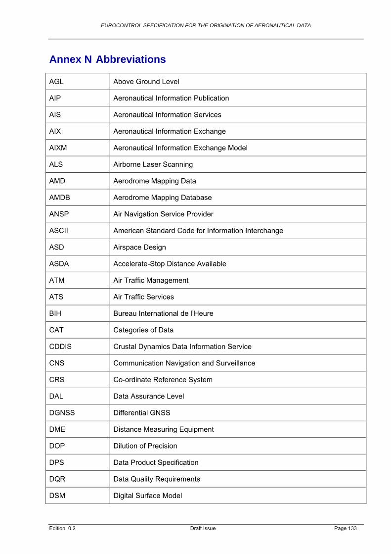
EUROCONTROL SPECIFICATION FOR THE ORIGINATION OF AERONAUTICAL DATA
Annex N Abbreviations
AGL Above Ground Level
AIP Aeronautical Information Publication
AIS Aeronautical Information Services
AIX Aeronautical Information Exchange
AIXM Aeronautical Information Exchange Model
ALS Airborne Laser Scanning
AMD Aerodrome Mapping Data
AMDB Aerodrome Mapping Database
ANSP Air Navigation Service Provider
ASCII American Standard Code for Information Interchange
ASD Airspace Design
ASDA Accelerate-Stop Distance Available
ATM Air Traffic Management
ATS Air Traffic Services
BIH Bureau International de l’Heure
CAT Categories of Data
CDDIS Crustal Dynamics Data Information Service
CNS Communication Navigation and Surveillance
CRS Co-ordinate Reference System
DAL Data Assurance Level
DGNSS Differential GNSS
DME Distance Measuring Equipment
DOP Dilution of Precision
DPS Data Product Specification
DQR Data Quality Requirements
DSM Digital Surface Model
Edition: 0.2 Draft Issue Page 133

EUROCONTROL SPECIFICATION FOR THE ORIGINATION OF AERONAUTICAL DATA
DSS Data Set Specifications
DTM Digital Terrain Model
EATMN European Air Traffic Management Network
EGM Earth Gravitational Model
EGNOS European Geostationary Navigation Overlay Service
ENPRM EUROCONTROL Notice of Proposed Rule Making
EPN EUREF Permanent Network
ERAF EUROCONTROL Regulatory and Advisory Framework
ETRF European Terrestrial Reference Frame
ETRS European Terrestrial Reference System
EU European Union
EUROCAE European Organisation for Civil Aviation Equipment
EUROCONTROL European Organisation for the Safety of Air Navigation
EVRF European Vertical Reference Frame
EVRS European Vertical Reference System
EXC Data Exchange
FAS Final Approach Segment
FATO Final Approach and Take-off
FIR Flight Information Region
FL Flight Level
FMS Flight Management System
FPD Instrument Flight Procedure Design
Ft Feet
GBAS Ground-Based Augmentation System
GNSS Global Navigation Satellite System
GPS Global Positioning System
GRS Geodetic Reference System
Edition: 0.2 Draft Issue Page 134

EUROCONTROL SPECIFICATION FOR THE ORIGINATION OF AERONAUTICAL DATA
GSFC Goddard Space Flight Center
IAG International Association of Geodesy
IAIP Integrated Aeronautical Information Package
ICAO International Civil Aviation Organisation
ICARD ICAO International Codes and Route Designators
ICS Implementation Conformance Statement
IERS International Earth Rotation and Reference Systems Service
IFP Instrument Flight Procedure
IGS International GNSS Service
ILS Instrument Landing System
IMU Inertial Measuring Unit
INSPIRE Infrastructure for Spatial Information in Europe
IRM IERS Reference Meridian
IRP IERS Reference Pole
ISO International Organisation for Standardisation
ITRF International Terrestrial Reference Frame
ITRS International Terrestrial Reference System
KGNSS Kinematic GNSS
Km Kilometres
LDA Landing Distance Available
MLS Microwave Landing System
MoC Means of Compliance
MSL Mean Sea Level
NAP Normaal Amsterdams Peils
NASA National Aeronautics and Space Administration
NIMA National Imagery and Mapping Agency
NM Nautical Miles
Edition: 0.2 Draft Issue Page 135

EUROCONTROL SPECIFICATION FOR THE ORIGINATION OF AERONAUTICAL DATA
NOAA National Oceanic and Atmospheric Administration
ODCS Obstacle Data Collection Surface
OGC Open Geospatial Consortium
ORCAM Originating Region Code Assignment Method
PBN Performance-based Navigation
POS Positioning and Orientation System
PPP Precise Point Positioning
PRO Data Processing
QUA Quality Assurance
REF Reference System Specification
RGNSS Relative GNSS
RINEX Receiver Independent Exchange Format
RNAV Area Navigation
RNP Required Navigation Performance
RNP AR Required Navigation Performance Authorization Required
RTK Real-time Kinematic
SAAM System for Traffic Assignment & Analysis at Macroscopic Level
SARPs Standards and Recommended Practices
SDG Specification Drafting Group
SES Single European Sky
SESAR Single European Sky Air Traffic Management Research
SID Standard Instrument Departure
SOPAC Scripps Orbit and Permanent Array Center
SSR Secondary Surveillance Radar
STAR Standard Terminal Arrival Route
SVY Survey
TLOF Touchdown and Lift-off Area
Edition: 0.2 Draft Issue Page 136
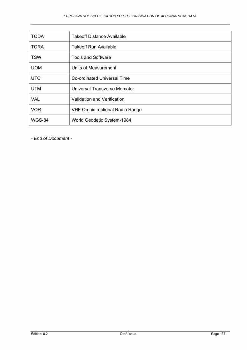
EUROCONTROL SPECIFICATION FOR THE ORIGINATION OF AERONAUTICAL DATA
Edition: 0.2 Draft Issue Page 137
TODA Takeoff Distance Available
TORA Takeoff Run Available
TSW Tools and Software
UOM Units of Measurement
UTC Co-ordinated Universal Time
UTM Universal Transverse Mercator
VAL Validation and Verification
VOR VHF Omnidirectional Radio Range
WGS-84 World Geodetic System-1984
- End of Document -