Embed Size (px)
Citation preview
TP Mohamed Haris et al
778
ABSTRACT
Aim: The aim of the study was to evaluate the force, moment, and moment/force ratio (M/F) generated by activating T loop, Kalra Simultaneous Intrusion and Retraction (KSIR) loop, Omega loop, and Teardrop loop made of titanium molybdenum alloy (TMA) wire with different preactivation bends at 1, 2, and 4 mm activation.
Materials and methods: Finite element method (FEM) models of the four loops were created and different preactivation bends were placed. The loops were then activated and analyzed for force, moment, and M/F ratio using ANSYS software.
Results: In loops without preactivation bends, highest force values were generated by Omega loop, whereas T loop had the least force value. The mean value for the M/F in the alpha segment was almost similar. In loops with preactivation bend, the force was highest in Teardrop loop, whereas T loop had the least force value. The mean value for the M/F in the alpha segment was almost similar in all the loops.
Conclusion: T loop with preactivation bend shows the most favorable properties.
Clinical significance: T loop is comparatively reliable for the frictionless mechanics for the space closure than the other loops evaluated in clinical use.
Keywords: Biomechanical properties, Finite element analysis, Kalra Simultaneous Intrusion and Retraction loop, Omega loop, T loop, Tear drop loop, Titanium molybdenum alloy.
How to cite this article: Haris TPM, Francis PG, Margaret VA, Roshan G, Menon V, Jojee V. Evaluation of Biomechanical Properties of Four Loops at Different Activation: A Finite Element Method Study. J Contemp Dent Pract 2018;19(7):778-784.
Evaluation of Biomechanical Properties of Four Loops at Different Activation: A Finite Element Method Study1TP Mohamed Haris, 2PG Francis, 3Vincy A Margaret, 4Gazanafer Roshan, 5Vineeth Menon, 6Venith Jojee
1-5Department of Orthodontics, MES Dental College, Malappuram Kerala, India6Department of Orthodontics, Malabar Dental College, Malappuram Kerala, India
Corresponding Author: TP Mohamed Haris, Department of Orthodontics, MES Dental College, Malappuram, Kerala, India e-mail: [email protected]
Source of support: Nil
Conflict of interest: None
INTRODUCTION
Extraction space closure is an important part of orth-odontic treatment. The space closure can be achieved by moving segments of teeth anterior and posterior to the extraction space into the space created by extraction of teeth depending on the case. This differential space closure is achieved by varying the force system between the anterior and posterior segments by duplicating the predetermined loop geometries to reproduce the required force system within the narrow ranges.
Understanding the biomechanics of loops is impor-tant. Otherwise, it can lead to complications, leading to irreversible damage to the patient. Over the years, dif-ferent loop configurations for closing spaces have been developed and used in both continuous and segmented arches to provide controlled tooth movement. Two impor-tant characteristics of closing loops used for orthodontic space closure are the M/F ratio and the load deflection (F/D) rate, influenced by the amount of activation.1
Effectiveness of loop designs can be tested and com-pared by computer software, such as finite element analysis (FEA).1 Finite element method is a mathematical method where the shape of complex geometric objects and their physical properties are computer constructed. Finite element analysis is a tool for numerical stress analysis, which has the advantage of being applicable to solids of irregular geometry that contain heterogeneous material properties.2 The FEA provides the orthodontist with quanti-tative data that can extend the understanding of physiologic reactions that occur within the dentoalveolar complex.2
The TMA wires are used more often for closing loops. Many TMA closing loops have a low F/D rate and the M/F ratio that change as a loop activates and deactivates. As a result, the teeth move through cycles of
original research10.5005/jp-journals-10024-2336
JcDP
Evaluation of Biomechanical Properties of Four Loops at Different Activation
The Journal of Contemporary Dental Practice, July 2018;19(7):778-784 779
JCDP
controlled crown tipping translation and root movement. Because traditional TMA closing loops are not capable of delivering an ideal M/F ratio of 10:1, generally residual moments, in the form of gable bends, are added, to reduce the amount of crown/root tipping.
It is difficult to estimate the correct amount of residual moment needed in each clinical situation. Therefore, it would be an advantage to have a loop capable of deliver-ing the ideal M/F ratio over the full range of activation, so that cycles of tipping and translation can be avoided. The design of the spring influences not only the M/F ratio but also the F/D rate. The addition of helix lowers the F/D rate without significantly affecting the M/F ratio. Load deflection can also be altered by changing the wire composition. A loop bent from wire with a low modulus of elasticity, such as TMA, will have a lower F/D rate than a stainless steel (SS) loop of the same configuration.
Hence, in the present study, we aim to use the FEM to model and compare the forces, moments, and M/F ratio of four different loops (T loop, KSIR loop, Omega loop, and Teardrop loop) made of TMA wire.
MATERIALS AND METHODS
The T loop, KSIR loop, Omega loop, and Teardrop loop for three-dimensional (3D) analysis with the FEM were assumed to be made of 0.017 × 0.025 inch rectangular TMA wire. A 3D beam element was used to construct the models. The loops were modeled with and without preactivation bends. The two extremities in all loops were 15 mm each.
Configuration of the Loops
T Loop
The T loop was given a total height of 7 mm and length of 10 mm.3 The loop was preactivated with six bends, result-ing in 19° to 20° of moment preactivation in both the alpha and beta legs. The first and second bends were placed in the T loop at the corners of the T, the third and fourth bends
were made at the base of the T. The legs were bent upward until they actually touched the corners of the T loop.
KSIR Loop
The KSIR was given a height of 7 mm and a length of 2 mm.4 A 90° V-bend was placed in the arch wire at the level of each U-loop. A 60° V-bend was located posterior to the center of the interbracket distance.
Teardrop Loop
The Teardrop loop was given a height of 7 mm and length of 3 mm. The preactivation bends given were 45° each at the alpha and beta segments.
Omega Loop
The Omega loop was given a height of 8 mm and length of 6 mm. The preactivation bends given were 45° each at the alpha and beta segments.
Methods
Accurate diagrams of the loops were prepared and the key points marked on each diagram; the key points were then analyzed. The boundary conditions were defined so that the terminal node in the alpha segment (anterior) was restrained (i.e., it was not able to move in the X, Y, or Z axes, and it was not able to rotate around these axes). The terminal node of the beta segment (posterior) was restrained in a similar way to the alpha segment, except that it was free to move along the horizontal leg of the posterior segment. This movement simulated the wire sliding distally through a molar tube. The cross-sectional area of TMA orthodontic wire (0.017 × 0.025 inch) was then calculated. The Young’s modulus of the TMA wire was assumed to be 90 GPa (16.5 × 10⁶ psi) and the Poisson ratio was equal to 0.33. The forces, moments, and the M/F ratios of each loop during activation and deactiva-tion (4, 2, and 1 mm) without preactivation bends (Figs 1 to 4) and with preactivation bends were determined.
Figs 1A and B: T loop without preactivation bend. (A) Base model, (B) Model after 4 mm activation
A B

TP Mohamed Haris et al
780
Figs 2A and B: KSIR loop without preactivation bends. (A) Base model, (B) Model after 4 mm activation
Figs 3A and B: Teardrop loop without preactivation bends. (A) Base model, (B) Model after 4 mm activation
Figs 4A and B: Omega loop without preactivation bends. (A) Base model, (B) Model after 4 mm activation
The following procedure was used for loops without a preactivation bend:
Loops without preactivation bends were inserted into each model in turn and modeled by defining a fixed point at the terminal node (i.e., the alpha position), by displacing the node at the other end (i.e., the beta posi-tion) and by deriving the forces and moments produced at the terminal nodes.
The following procedure was used for loops with a preactivation bend:
A fixed point at the terminal node (beta position) was defined. This simulated the insertion of the wire into the molar tube. The alpha end was displaced so that the
alpha end node remained at the same vertical level as the bracket slot. This simulated displacement of the anterior part of the loop incisally so as to keep it level with the bracket slot. The alpha segment of the loop crossed the bracket slot at an angle, which was directly related to the amount of the preactivation. To simulate engage-ment of the wire in the brackets, a rotation was added to the alpha end until the horizontal leg was completely horizontal and collinear with the bracket slot. The exact displacement at the alpha end node was recorded to obtain information about the amount of cross-over pro-duced when the wire was “engaged.” This point was the neutral position for all loops (zero force instant) and the
A
A
A
B
B
B
Evaluation of Biomechanical Properties of Four Loops at Different Activation
The Journal of Contemporary Dental Practice, July 2018;19(7):778-784 781
JCDP
starting point for all activations. The different amounts of loop activation were then applied sequentially and recorded. The analyses were performed on a Pentium IV personal computer by ANSYS version 12. The output data for the forces and the moments were assessed at the terminal nodes.
RESULTS
The force, moment, and M/F ratio of the four loops were calculated and analyzed using analysis of variance F test method and the descriptive statistics.
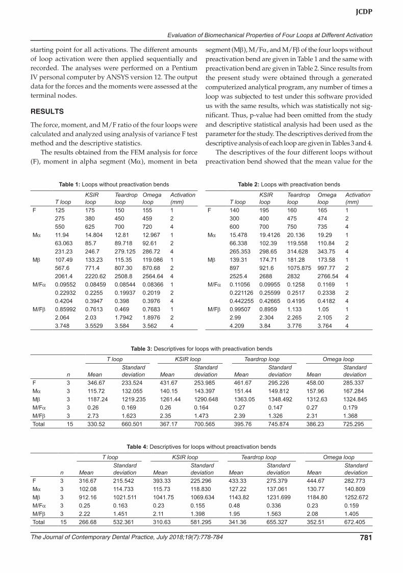
The results obtained from the FEM analysis for force (F), moment in alpha segment (Mα), moment in beta
segment (Mβ), M/Fα, and M/Fβ of the four loops without preactivation bend are given in Table 1 and the same with preactivation bend are given in Table 2. Since results from the present study were obtained through a generated computerized analytical program, any number of times a loop was subjected to test under this software provided us with the same results, which was statistically not sig-nificant. Thus, p-value had been omitted from the study and descriptive statistical analysis had been used as the parameter for the study. The descriptives derived from the descriptive analysis of each loop are given in Tables 3 and 4.
The descriptives of the four different loops without preactivation bend showed that the mean value for the
Table 4: Descriptives for loops without preactivation bends
n
T loop KSIR loop Teardrop loop Omega loop
MeanStandard deviation Mean
Standard deviation Mean
Standard deviation Mean
Standard deviation
F 3 316.67 215.542 393.33 225.296 433.33 275.379 444.67 282.773Mα 3 102.08 114.733 115.73 118.830 127.22 137.061 130.77 140.809Mβ 3 912.16 1021.511 1041.75 1069.634 1143.82 1231.699 1184.80 1252.672M/Fα 3 0.25 0.163 0.23 0.155 0.48 0.336 0.23 0.159M/Fβ 3 2.22 1.451 2.11 1.398 1.95 1.563 2.08 1.405Total 15 266.68 532.361 310.63 581.295 341.36 655.327 352.51 672.405
Table 1: Loops without preactivation bends
T loopKSIR loop
Teardrop loop
Omega loop
Activation (mm)
F 125 175 150 155 1275 380 450 459 2550 625 700 720 4
Mα 11.94 14.804 12.81 12.967 163.063 85.7 89.718 92.61 2231.23 246.7 279.125 286.72 4
Mβ 107.49 133.23 115.35 119.086 1567.6 771.4 807.30 870.68 22061.4 2220.62 2508.8 2564.64 4
M/Fα 0.09552 0.08459 0.08544 0.08366 10.22932 0.2255 0.19937 0.2019 20.4204 0.3947 0.398 0.3976 4
M/Fβ 0.85992 0.7613 0.469 0.7683 12.064 2.03 1.7942 1.8976 23.748 3.5529 3.584 3.562 4
Table 2: Loops with preactivation bends
T loopKSIR loop
Teardrop loop
Omega loop
Activation (mm)
F 140 195 160 165 1300 400 475 474 2600 700 750 735 4
Mα 15.478 19.4126 20.136 19.29 166.338 102.39 119.558 110.84 2265.353 298.65 314.628 343.75 4
Mβ 139.31 174.71 181.28 173.58 1897 921.6 1075.875 997.77 22525.4 2688 2832 2766.54 4
M/Fα 0.11056 0.09955 0.1258 0.1169 10.221126 0.25599 0.2517 0.2338 20.442255 0.42665 0.4195 0.4182 4
M/Fβ 0.99507 0.8959 1.133 1.05 12.99 2.304 2.265 2.105 24.209 3.84 3.776 3.764 4
Table 3: Descriptives for loops with preactivation bends
n
T loop KSIR loop Teardrop loop Omega loop
MeanStandard deviation Mean
Standard deviation Mean
Standard deviation Mean
Standard deviation
F 3 346.67 233.524 431.67 253.985 461.67 295.226 458.00 285.337Mα 3 115.72 132.055 140.15 143.397 151.44 149.812 157.96 167.284Mβ 3 1187.24 1219.235 1261.44 1290.648 1363.05 1348.492 1312.63 1324.845M/Fα 3 0.26 0.169 0.26 0.164 0.27 0.147 0.27 0.179M/Fβ 3 2.73 1.623 2.35 1.473 2.39 1.326 2.31 1.368Total 15 330.52 660.501 367.17 700.565 395.76 745.874 386.23 725.295
TP Mohamed Haris et al
782
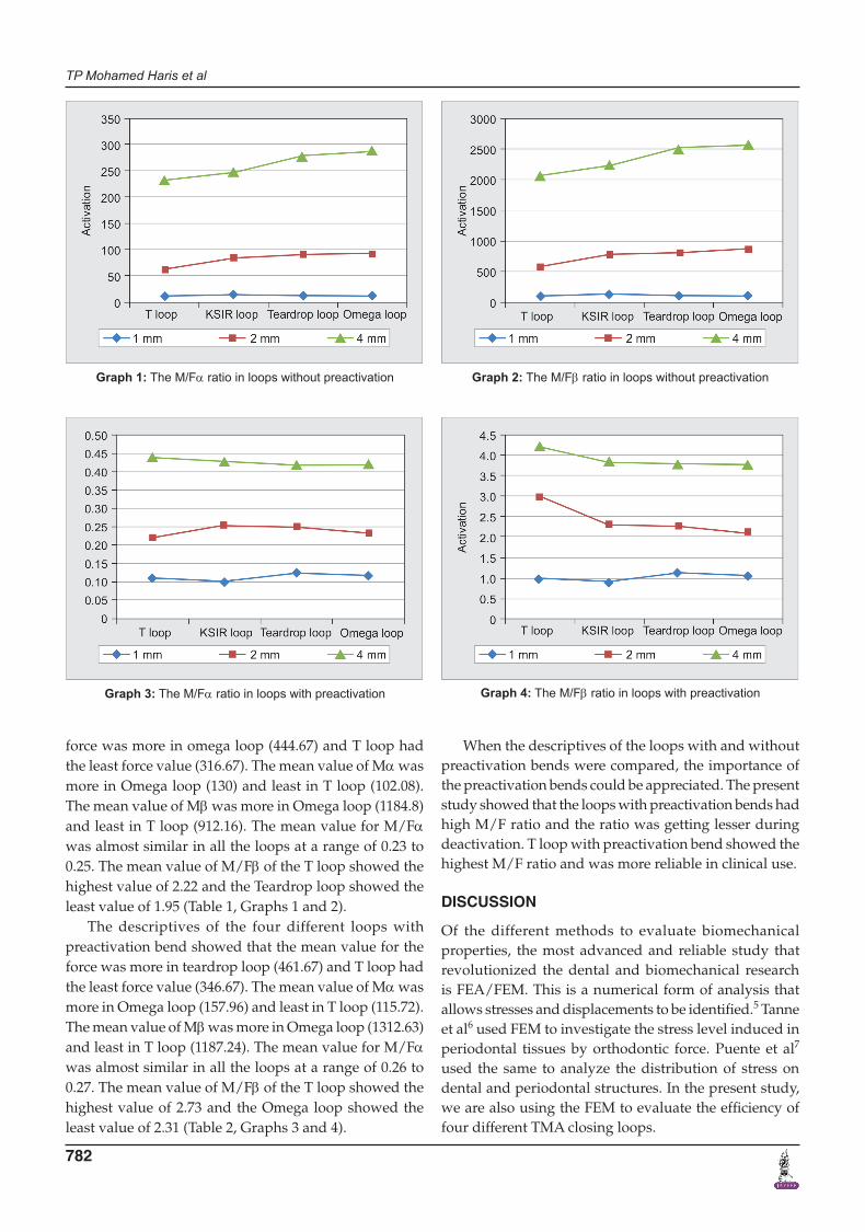
force was more in omega loop (444.67) and T loop had the least force value (316.67). The mean value of Mα was more in Omega loop (130) and least in T loop (102.08). The mean value of Mβ was more in Omega loop (1184.8) and least in T loop (912.16). The mean value for M/Fα was almost similar in all the loops at a range of 0.23 to 0.25. The mean value of M/Fβ of the T loop showed the highest value of 2.22 and the Teardrop loop showed the least value of 1.95 (Table 1, Graphs 1 and 2).
The descriptives of the four different loops with preactivation bend showed that the mean value for the force was more in teardrop loop (461.67) and T loop had the least force value (346.67). The mean value of Mα was more in Omega loop (157.96) and least in T loop (115.72). The mean value of Mβ was more in Omega loop (1312.63) and least in T loop (1187.24). The mean value for M/Fα was almost similar in all the loops at a range of 0.26 to 0.27. The mean value of M/Fβ of the T loop showed the highest value of 2.73 and the Omega loop showed the least value of 2.31 (Table 2, Graphs 3 and 4).
When the descriptives of the loops with and without preactivation bends were compared, the importance of the preactivation bends could be appreciated. The present study showed that the loops with preactivation bends had high M/F ratio and the ratio was getting lesser during deactivation. T loop with preactivation bend showed the highest M/F ratio and was more reliable in clinical use.
DISCUSSION
Of the different methods to evaluate biomechanical properties, the most advanced and reliable study that revolutionized the dental and biomechanical research is FEA/FEM. This is a numerical form of analysis that allows stresses and displacements to be identified.5 Tanne et al6 used FEM to investigate the stress level induced in periodontal tissues by orthodontic force. Puente et al7 used the same to analyze the distribution of stress on dental and periodontal structures. In the present study, we are also using the FEM to evaluate the efficiency of four different TMA closing loops.
Graph 1: The M/Fα ratio in loops without preactivation Graph 2: The M/Fβ ratio in loops without preactivation
Graph 3: The M/Fα ratio in loops with preactivation Graph 4: The M/Fβ ratio in loops with preactivation
Evaluation of Biomechanical Properties of Four Loops at Different Activation
The Journal of Contemporary Dental Practice, July 2018;19(7):778-784 783
JCDP
During the selection of the best indicated model for each case, some variables, such as loop design, thick-ness and properties of the wire used, type of movement desired, and amount of force necessary must be taken into consideration. The efficacy of dental movement is directly related to the quantity of force used. Thus, Burstone8 suggested the use of light forces and, whenever possible, continuous forces. Thus, the aim of the present study was to evaluate the M/F ratio of four different loops made of TMA wire using FEM analysis.
Over the past years, recent developments in mecha-notherapy and biomechanics have led to important breakthroughs in orthodontic treatments. New devices and materials were introduced in order to improve the clinical success. Titanium and titanium-based alloys have been used in orthodontics for more than half a century.9 The TMA exhibits properties ideal for use in loops, such as lower modulus of elasticity, good formability, and high resiliency.10 Hence, TMA alloy was chosen as the arch wire material in the study.
From the results obtained from the present study, it is observed that the T loop has higher M/F ratio, which is possibly because of the increase in arch wire length incorporated in the loop than the other loops. As the activation decreased, moment, force, and the M/F ratio of each loop also decreased. Even though there was a significant decrease in the force and moment, T loops stood top in the M/F ratio, and this was probably because of the geometry of the loop. This is in accordance with the study conducted by Chen et al.11 According to them, increase in vertical and horizontal dimension reduces the F/D rate. A smaller loop increases the force and stiffness dramatically, but reduces the M/F ratio.
In a study conducted by Safavi et al12 using SS wires to form the loops revealed at an activation of 1 mm, the M/F produced was 1.7. The present study revealed that at an activation of 1 mm, the M/F produced was 0.99. This change was because of the change in properties of the alloy. For a given cross section, TMA can be deflected approximately twice as far as SS without permanent deformation, which delivers force values less than half that of SS.8
The present study is in accordance with the study conducted by Rodrigues et al.13 They compared the properties of Teardrop loop with beta titanium and SS and concluded that the beta titanium loops produce lower amount of horizontal force and F/D ratio than the SS loops. According to the study conducted by Vibhute et al,14 Teardrop loop with a preactivation bend of 34° provided 82 to 303 g of force and 1.7 to 7.3:1 proportion of M/F ratio from its neutral position to +2 mm activa-tion. Their study is not in accordance with the present study. Even though the force produced is similar, the
M/F ratio is less in the present study when comparing with their study. This change is probably because of the difference in the dimension of the loop. The dimension of the Teardrop loop which they designed had a height of 10 mm and a width of 8 mm, while the dimension of the same loop in the present study was given a height of 7 mm and a width of 2 mm.
When preactivation bends were added in the plain loops, there was an increase in the force level, as well as the moment and the M/F ratio. The force system gener-ated by the T-loop spring was controlled by the integra-tion of the preactivated bends, the activation amount, and the position of the spring in the interbracket distance. Hoenigl et al15 evaluated a centralized T-loop force system by first activating it at the maximum level and then deactivating it gradually until it reached the lowest level of deactivation. They concluded that the force system generated by this type of spring provides movements from a controlled crown tip back to a radicular correction.
Unfortunately, with this kind of investigation, some limitations were inevitable. These include the rather simplistic mathematical modeling method, which may sometimes give only a rough force and moment value. In the present FEM study, we compared the loops with their moment, force, and M/F ratios. We came up with a conclu-sion that Teardrop loop and Omega loop showed similar and least M/F ratio. The KSIR loop showed less difference when compared with the T loop. Adding preactivation bends increased the force, moment, and M/F ratio.
CONCLUSION
The present in vitro study was designed to compare the force, moment, and M/F ratio of four different loops (T loop, KSIR loop, Teardrop loop, and Omega loop) with and without preactivation bends, using the FEM. The present study showed that the loops with preactiva-tion bends had high M/F ratio and the ratio was getting lesser during deactivation. T loop with preactivation bend showed the highest M/F ratio, and results prove that T loop is comparatively reliable for the frictionless mechanics for the space closure than the other loops evaluated in the clinical use. However, all the in vivo conditions cannot be simulated in an in vitro study and hence, a well-controlled clinical trial has to be performed in order to attain a desirable M/F ratio.
REFERENCES
1. Raboud D, Faulkner M, Lipsett A, Haberstock D. Three-dimensional effects in retraction appliance design. Am J Orthod Dentofac Orthop 1997 Oct;112(4):378-392.
2. Ren Y, Maltha JC, Kuijpers-Jagtman AM. Optimum force magnitude for orthodontic tooth movement (a systematic literature review). Angle Orthod 2003 Feb;73(1):86-92.
TP Mohamed Haris et al
784
3. Nanda R. Biomechanics in clinical orthodontics. Philadelphia, PA: Saunders; 1997.
4. Kalra V. Simultaneous intrusion and retraction of the anterior teeth. J Clin Orthod 1998 Sep;32(9):535-540.
5. Konda P, Tarannum, SA. Basic principles of finite element method and its applications in orthodontics. J Pharmaceutical Biomed Sci 2012;16(16):1-8.
6. Tanne K, Sakuda M, Burstone C. Three-dimensional finite element analysis for stress in the periodontal tissue by orth-odontic forces. Am J Orthod Dentofac Orthop 1987;92(6): 499-505.
7. Puente M, Galbán L, Cobo J. Initial stress differences between tipping and torque movements. A three-dimensional finite element analysis. Eur J Orthod 1996 Aug;18(1):329-339.
8. Burstone CJ. The segmented arch approach to space closure. Am J Orthod 1982 Nov;82(5):361-378.
9. Burstone C, Goldberg A. Beta titanium: a new orthodontic alloy. Am J Orthod 1980 Feb;77(2):121-132.
10. Szuhanek CA, Fleser T, Glavan FL. Mechanical behaviour of orthodontic TMA wires. Wseas Trans Biol Biomed 2010 Jul;7(3):277-286.
11. Chen J, Markham DL, Katona TR. Effects of T-loop geometry on its forces and moments. Angle Orthod 2000 Feb;70(1):48-51.
12. Safavi MR, Geramy A, Khezri AK. M/F ratios of four different closing loops: 3D analysis using the finite element method (FEM). Aust Orthod J 2006 Nov;22(2):121-126.
13. Rodrigues EU, Maruo H, Guariza Filho O, Tanaka O, Camargo ES. Mechanical evaluation of space closure loops in orthodon-tics. Braz Oral Res 2011 Jan-Feb;25(1):63-68.
14. Vibhute PJ, Srivastava SS, Kohli VS. Evaluation of the teardrop and snail loop designs for force system with two different preactivations: computer loop simulation program study. J Indian Orthod Soc 2009;43(3):50-60.
15. Hoenigl KD, Freudenthaler J, Marcotte MR, Bantleon HP. The centered T-loop—a new way of preactivation. Am J Orthod Dentofacial Orthop 1995;108(2):149-53.