Embed Size (px)
Citation preview

Evaluation of the Compatibility of Repair Materials for ConcreteStructures
Giri Venkiteela1),*, Matthew Klein2), Husam Najm3), and Perumalsamy Naidu Balaguru3)
(Received October 21, 2016, Accepted June 16, 2017, Published online September 18, 2017)
Abstract: This study evaluates the compatibility of repair materials for concrete bridge decks. A new compatibility test set-up
was designed and tested based on the concrete bridge deck cracking and delamination mechanism theory. The repair materials used
in this study include lab formulated inorganic nano-aluminum silicates and commercially available organic two-part epoxy
systems. Two different lab test-setups are proposed in this study: a prototype and a full-scale test. The developed test procedures
were effective in communicating results in terms of compatibility of material properties, performance and quality. The prototype
beams test can successfully serve as a small scale screening test providing insights on materials selection for the full-scale beam
tests. The full-scale beams demonstrated the compatibility of the repaired system by providing data on authentic field conditions.
Based on the observations it can be concluded that the proposed test setup is effective in examining the concrete bridge deck repair
materials performance and selection, and compatibility in terms of mechanical properties and further guarantee the repaired
structure safety.
Keywords: concrete repair, concrete bridge deck repair, compatibility test, organic and inorganic repair materials.
1. Introduction
Aging infrastructure is a growing concern for federal,state, and local governments across the United States and formany countries worldwide. The Federal Highway Admin-istration (FHWA) estimates that one in nine of the nation’sbridges is rated as structurally deficient and the average ageof the nation’s 607,380 bridges is about 42 years (ASCE(American Society of Civil Engineers) 2017; AASHTO(American Association of State Highway and TransportationOfficials) 2008; NJDOT (New Jersey Department ofTransportation) 2007).1 Thus county, city, state, and federalagencies need to increase budgets enormously to fix thesedeficient bridges. Many research studies focused on mate-rials, systems and technologies to improve the life span ofdeficient bridge structures (FHWA (Federal Highway
Administration) 2009; Floyd 2009; Stratton and McCollom1974; Barbara and Wayne 1988; Camille and Debs 2007). Itwas reported that sound rehabilitation principles and tech-niques also play a crucial role in successful concrete reha-bilitation process (Chase and Laman 2000; Arockiasamy2000; FDOT (Florida Department of Transportation) 1999;NCHRP (National Cooperative Highway Research Program)Synthesis 375 2007).In bridge superstructure, deck plays a crucial role in bridge
performance and have a direct impact from flowing trafficand environment (such as snow accumulations and heavyrains etc.). It is extremely important for bridge owners tomaintain its integrity and structural soundness for safety andsudden failures. Thus periodic inspection and maintenance isoften required. In most bridges, the bridge decks are con-structed using reinforced concrete. Regardless of the type ofsuperstructure, the number and length of spans, and the typeof concrete used, certain cracks develop in every reinforcedconcrete bridge deck (FHWA (Federal Highway Adminis-tration) 2009; Chase and Laman 2000; FDOT (FloridaDepartment of Transportation) 1999). With time, thesecracks lead to chloride penetration and corrosion of rein-forcement. Corrosion of steel bars can lead to a concentra-tion of internal stresses in the concrete and reduction in bondoften resulting in further cracking and deterioration. Differ-ent types of concrete cracks are observed in concrete decks(Krauss and Rogalla 1996; ElSafty and Abdel-Mohti 2013;Ramseyer and Kang 2012; Soltani et al. 2013; Labib et al.
1)New Jersey Department of Transportation, Trenton,
NJ 08625, USA.
*Corresponding Author; E-mail:
2)Technical Service Center, U.S. Department of the
Interior Bureau of Reclamation, Denver, CO 80225, USA.3)Department of Civil and Environmental Engineering,
Rutgers, the State University of New Jersey, Piscataway,
NJ 08854, USA.
Copyright � The Author(s) 2017. This article is an open
access publication
1 http://www.nytimes.com/2015/07/27/nyregion/aging-infrastructure-plagues-nations-busiest-rail-corridor.html?_r=0.
International Journal of Concrete Structures and MaterialsVol.11, No.3, pp.435–445, September 2017DOI 10.1007/s40069-017-0208-5ISSN 1976-0485 / eISSN 2234-1315
435

2013). These include vertical cracks which can be detectedby visual inspection when there is no overlay and horizontalcracks, also called delaminations, which can cause abreaking-away of the concrete deck. Concrete delaminationin bridge deck is a serious issue for bridge maintenance,because it cannot easily be identified as surface cracks andcan lead to sudden failure of deck. Thus identifying andrepairing of these cracks in concrete bridge decks is crucialfor guaranteeing the quality and safety (Smoak 1996; PCA(Portland Cement Association) Final Report 1970; ACI(American Concrete Institute) Committee 224 report 2001).Several repair procedures are often employed in the field
for bridge decks based on location and size of cracks, whichinclude Portland cement mortar filling, dry packing, epoxybonded dry packing, shotcreting, epoxy bonded mortar fill-ing, polymer concrete, alkyl-alkoxy siloxane sealing com-pound and resin injection etc. (Floyd 2009; Stratton andMcCollom 1974; Soriano 2002; Davidovits 1991; Matthewet al. 2011). Both narrow and wide dormant cracks (indormant cracks width does not change over time may berepaired by routing and sealing, which is the simplest andmost common technique for crack repair. Narrow, dormantcracks may be effectively sealed by epoxy injection (Do andKim 2012; Iowa Department of Transportation 2008; Rodleret al. 1989; Leivo et al. 2006). In some cases concretestructural elements can be bonded together with repairmaterials.2
Currently, There are various materials can be used forconcrete deck crack repair which include Portland cementbinders, polymers such as high molecular weightmethacrylate and low viscosity epoxies etc. (Floyd 2009;Barbara and Wayne 1988). Among all these materials, themost commonly used repair materials are organic epoxies. Inrecent years, many research studies focused on geo-polymermaterials for infrastructure construction and maintenance. Itwas observed that the performance of these inorganic com-pounds (Soriano 2002; Davidovits 1991; Hammell 2000;Garon 2000; Richard et al. 1997; Woo et al. 2008) aresuperior over traditional organic materials. It is certain thatthese newly developed materials such as inorganic com-pounds has huge role to play in future infrastructure main-tenance. It is always debatable which materials should beused for bridge deck repair and it is often big challenge foragencies and bridge owners to make such decisions. Forconcrete structures under service conditions (with bothtraffic and environmental loadings), bond strength is some-time evaluated as an important property for crack repairmaterials. There are several standard test methods availableto evaluate bond strength indirectly using different types ofrepaired concrete samples (ASTM (the American Society forTesting and Materials) 2005; ASTM (the American Societyfor Testing and Materials) 2008; ASTM (the AmericanSociety for Testing and Materials) 2013).To better understand the performance of repair materials,
it is important to study their compatibility along with bondstrength. However, there are no standard methods for
determining the compatibility of repair materials withrespect to concrete substrate. For the repair material to becompletely compatible with concrete, the internal stresseswould be able to be transferred across the repair plane anddistribute over the entire cross-sectional area of the con-crete. When concrete is used in flexural applications tensilereinforcement is required due to the low tensile capacity ofthe concrete. In concrete, steel reinforcement is added toprovide the missing tensile reinforcement. Since thecapacities of each material are different, the equivalent areain the concrete is greater to counteract the tensile forces inthe steel in order to balance out the flexural internalstresses (Elgabbas et al. 2016). However, the effective areaof the concrete is only a quarter to a fifth of the total cross-sectional area of the beam. When defects occur in thiscompression zone, the internal stresses must concentratearound the defect and reduce the load capacity of theconcrete. If a repair material is used, it should be able tobond the concrete together so that the entire load resistingarea can be utilized. When a beam is composed of severalsmaller cross-sections that are not mechanically or chemi-cally fastened to one another, the total flexural capacity ofthe beam is controlled by the smallest cross-section alongthe span. Thus if the compression zone of the concrete isremoved, the stresses must redistribute to the concrete areacloser to the tensile fibers which reduces the moment armof the flexural strength and reduces the moment capacity ofthe beam.The objective of this study is to evaluate the compati-
bility of repair materials with respect to the correspondingconcrete substrate. The repair materials used in this studyinclude lab formulated inorganic nano-aluminum silicatesand commercially available organic two-part epoxy sys-tems. A compatibility test for the repair materials wasdeveloped and tested in this study, based on the concretebridge deck cracking and delamination mechanism theory.Two different lab test-setups are proposed in this study: aprototype and a full-scale test. The developed test proce-dures were effective in producing results for repair mate-rials properties and for performance and quality in terms ofcompatibility. Based on the observations it can be con-cluded that the proposed test setup is effective in examin-ing the concrete bridge deck repair materials performanceand selection, and compatibility in terms of mechanicalproperties and further guarantee the repaired structuresafety.
2. Concrete Cracking and Delamination
Delaminations often occur in bridge decks due to corro-sion in the reinforcing bars causing tensile stresses to theconcrete and flexural loading conditions inducing shearstresses along the top mat of reinforcement (Krauss andRogalla 1996; ElSafty and Abdel-Mohti 2013). A typicalbridge consists of vertical supports spanned by horizontalbeams. The bridge deck is supported on several beamswhich are typically spaced between 4 feet to 10 feet. The2 http://www.uscproducts.com/featured-projects/tappen-zee-bridge/.
436 | International Journal of Concrete Structures and Materials (Vol.11, No.3, September 2017)
bridge deck is usually anywhere from 8 inches to 12 inchesthick but can be greater if required. Usually the deck featurestwo layers of reinforcement called mats and consists of twosets of bars located perpendicular to each other for transverseand longitudinal flexural loads near the outer edge of theconcrete as shown in Fig. 1.When concrete is loaded in flexure, small flexural cracks
form as a result of the transfer of tensile forces from the con-crete to the steel reinforcement. In addition, when loads areapplied to the superstructure, the opposing tensile and com-pression stresses from the ensuing flexural forces provideshear loads at or near the neutral axis (see Fig. 2). Since thestrength of concrete and steel are different the neutral axis isnot located at the mid-point as would be the case in ahomogenous material but rather can be located at approxi-mately 1/5 the thickness of the deck. This location often cor-responds to the location of one of the two reinforcing matsdescribed above. Most concrete decks are cast continuouslyacross the supporting girders and therefore the compressionand tensile inducing shear zones of the deck alternate withrespect to the girder spacing. The zones located at the topsurface of the bridge deck are where themaximum stresses canoccur—‘‘compressive’’ shear stresses near the deck supportsand ‘‘tensile’’ shear stresses at the midsection.Another force that contributes to bridge deck delamina-
tions is caused by expansion of the steel reinforcement dueto corrosion. Water has been known to infiltrate the steel
reinforcement by way of the flexural cracks that form duringservice loads. When water, oxygen and steel combine, theoxidized product forms known commonly as rust. This formof iron is known to be less dense than the parent materialsthereby exerting tensile stresses in the confining concretearound the bar.Therefore, the main stresses acting on the concrete causing
delaminations, spalling, and eventually loss of the concretecover and potholes, are tensile forces from corroding steelreinforcement and/or shear forces resulting from theopposing compressive and tensile stresses inherent in flex-ural loading. This analysis is used to design a test set-up forfinding how effective the concrete repair is and determinerepair material compatibility with concrete. A beam isdesigned with notches at either end at the compressivereinforcement (top mat) layer (see Fig. 3). Then blocks areformed to fill the notches to the size of a rectangular beamafter being fixed to the notched beam using the repairmaterial.
3. Materials
3.1 Repair MaterialsIn this study, the inorganic and organic repair materials
that were selected include a lab formulated inorganic nano
Fig. 1 Typical reinforcement placement in bridge deck.
Fig. 2 Internal stress distribution in third-point bending.
Fig. 3 Diagram of compatibility beam.
International Journal of Concrete Structures and Materials (Vol.11, No.3, September 2017) | 437

alumino-silicates and commercially available two part epoxysystem. The epoxy resin boasts low viscosity, high modulusand non-shrinkage properties. The reported viscosity, givenin the product data sheet, is about 280 cps and cures inapproximately 24 h (SealBoss 2012). The inorganic mixdesign was obtained based on materials performance ondifferent tests including flexural tests, slant shear tests,freeze/thaw durability and wetting durability tests (Matthew2013). The final mix design of the inorganic material hasstandard silica/alumina ratio and optimized zinc oxideactivator.
3.2 Concrete Mix-DesignThe mix design for the prototype small beams and the full-
scale beams include Portland Type I cement, coarse aggre-gates, fin aggregates (sand), fly ash, water, and superplasti-cizer (Matthew 2013). The mix design proportions areshown in Table 1. The samples were removed from moldsafter a minimum of 24 h and were cured in a in a fog roomfor a minimum of 28 days.
4. Test Procedure
4.1 Concrete Beams Design and Casting4.1.1 Prototype BeamsIn order to test compatibility between the repair materials
and concrete, small-scale (prototype) beams samples wereprepared and cast. The small beam specimens were helpfulin verifying some assumptions and the observations fromtheir testing and test results helped in designing representa-tive full-scale beams and avoiding problems during the testitself. The dimensions were scaled from the proposed full-scale samples with the length fixed at 14 inches. The con-crete in the flexural samples was tested with a compressivestrength of 5500 psi. The dimensions for the width and depthwere 1–1/8 inch. The notches were 5/16 inch and 1/4 inchfor the approximate neutral axis. Length of the notch was set
at L/3 and was equal to 4.75 inches including the 1 inchoverhang at the end as shown in Fig. 4. Since the beamswere created from existing concrete without internal tensilereinforcement, the beams were strengthened using carbonfibers after the notches were repaired with the specifiedrepair materials as shown in Fig. 5. Two tows of 35 k ZoltecPanex fibers were fixed to the bottom of the beams using atypical 2-part epoxy for bonding carbon fibers to concretebeams.The beams were notched and then repaired using selected
inorganic and organic repair compounds. Two similar inor-ganic materials compounds (inorganic 1 and inorganic 2)were formulated based on silica/alumina ratio as specified inSect. 2.1. Similarly for the organic materials, two epoxysystems (epoxy 1 and epoxy 2) were used (Matthew 2013).After the repaired beams were allowed to cure at room
temperature for at least one week they were tested usingMTS Sintech 10/GL load testing machine with 10 kip loadcapacity as shown in Fig. 6.
4.1.2 Full-Scale BeamsThe dimensions of the full-scale beam were chosen to
accommodate equipment where a 600 kip beam testingmachine was used. The machine is optimized for 8 foot
Table 1 Mix proportions for small and full-scale beam specimens.
Material Coarse aggregates Fine aggregates Water Cement SuperP
Quantity 945 lb/yd3 1647 lb/yd3 424 lb/yd3 817 lb/yd3 9.3 lb/yd3
Fig. 4 Prototype beams.
Fig. 5 Completed prototype beams.
Fig. 6 Prototype beam test.
438 | International Journal of Concrete Structures and Materials (Vol.11, No.3, September 2017)
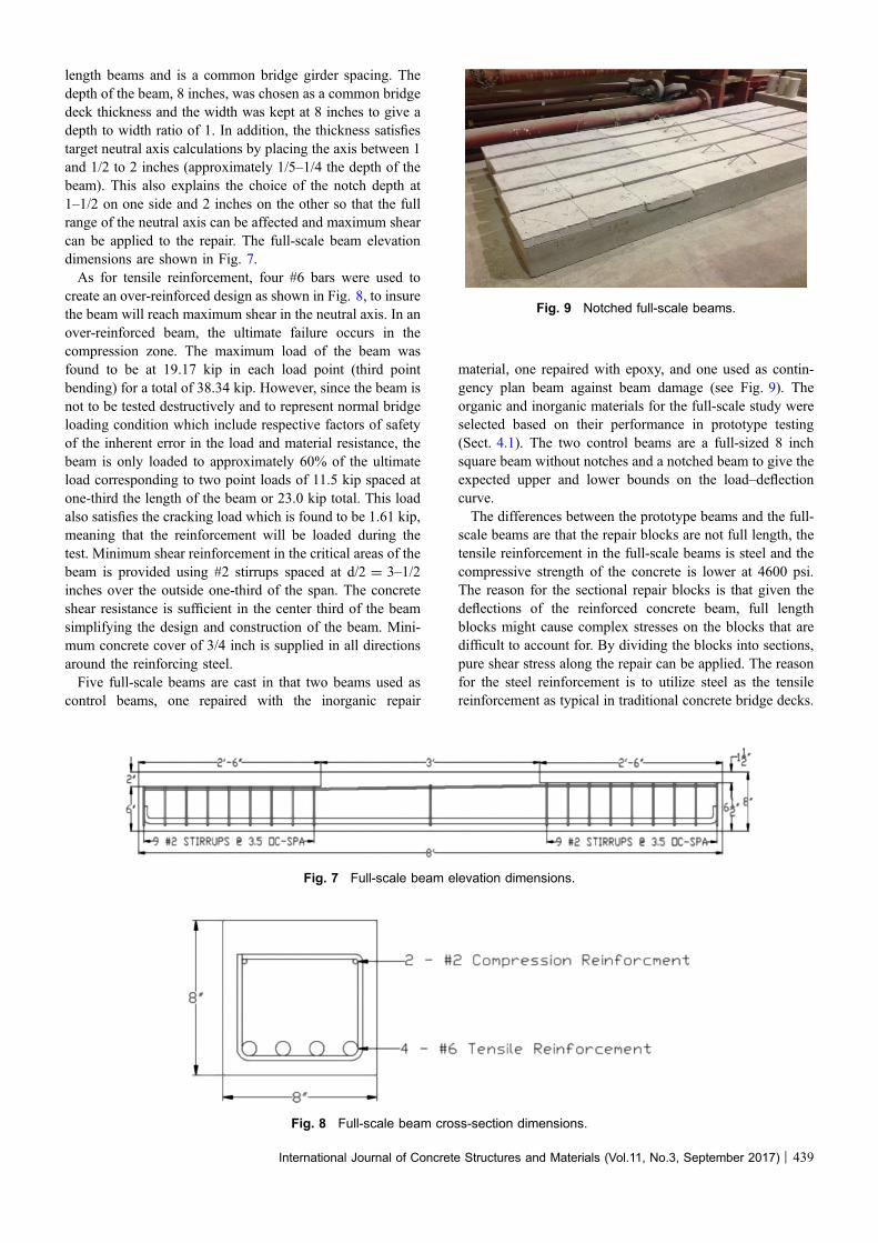
length beams and is a common bridge girder spacing. Thedepth of the beam, 8 inches, was chosen as a common bridgedeck thickness and the width was kept at 8 inches to give adepth to width ratio of 1. In addition, the thickness satisfiestarget neutral axis calculations by placing the axis between 1and 1/2 to 2 inches (approximately 1/5–1/4 the depth of thebeam). This also explains the choice of the notch depth at1–1/2 on one side and 2 inches on the other so that the fullrange of the neutral axis can be affected and maximum shearcan be applied to the repair. The full-scale beam elevationdimensions are shown in Fig. 7.As for tensile reinforcement, four #6 bars were used to
create an over-reinforced design as shown in Fig. 8, to insurethe beam will reach maximum shear in the neutral axis. In anover-reinforced beam, the ultimate failure occurs in thecompression zone. The maximum load of the beam wasfound to be at 19.17 kip in each load point (third pointbending) for a total of 38.34 kip. However, since the beam isnot to be tested destructively and to represent normal bridgeloading condition which include respective factors of safetyof the inherent error in the load and material resistance, thebeam is only loaded to approximately 60% of the ultimateload corresponding to two point loads of 11.5 kip spaced atone-third the length of the beam or 23.0 kip total. This loadalso satisfies the cracking load which is found to be 1.61 kip,meaning that the reinforcement will be loaded during thetest. Minimum shear reinforcement in the critical areas of thebeam is provided using #2 stirrups spaced at d/2 = 3–1/2inches over the outside one-third of the span. The concreteshear resistance is sufficient in the center third of the beamsimplifying the design and construction of the beam. Mini-mum concrete cover of 3/4 inch is supplied in all directionsaround the reinforcing steel.Five full-scale beams are cast in that two beams used as
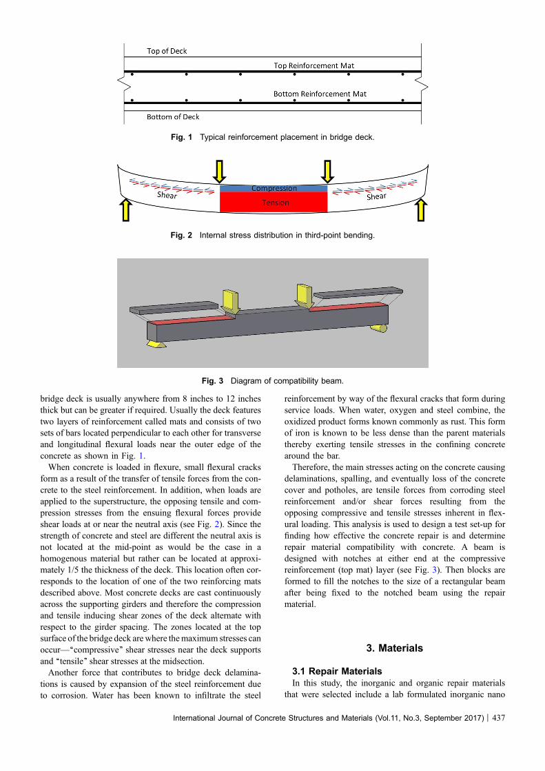
control beams, one repaired with the inorganic repair
material, one repaired with epoxy, and one used as contin-gency plan beam against beam damage (see Fig. 9). Theorganic and inorganic materials for the full-scale study wereselected based on their performance in prototype testing(Sect. 4.1). The two control beams are a full-sized 8 inchsquare beam without notches and a notched beam to give theexpected upper and lower bounds on the load–deflectioncurve.The differences between the prototype beams and the full-
scale beams are that the repair blocks are not full length, thetensile reinforcement in the full-scale beams is steel and thecompressive strength of the concrete is lower at 4600 psi.The reason for the sectional repair blocks is that given thedeflections of the reinforced concrete beam, full lengthblocks might cause complex stresses on the blocks that aredifficult to account for. By dividing the blocks into sections,pure shear stress along the repair can be applied. The reasonfor the steel reinforcement is to utilize steel as the tensilereinforcement as typical in traditional concrete bridge decks.
Fig. 7 Full-scale beam elevation dimensions.
Fig. 8 Full-scale beam cross-section dimensions.
Fig. 9 Notched full-scale beams.
International Journal of Concrete Structures and Materials (Vol.11, No.3, September 2017) | 439

The lower compressive strength was specified for the full-scale tests to simulate typical field conditions.The repair was prepared by wrapping half of the horizontal
repair plane with tape to prevent the repair material fromleaking out and causing voids. The repair materials wereapplied by pouring the mix in the dam created by the tapeand attach each block section into place. The blocks werepressed firmly into the repair material. Excess amounts ofmaterial were not allowed to drain so as to reduce theamount of voids. If the blocks were higher than the middlecompressive zone of the concrete beam, it would not affectthe overall strength of the beam since the strength is limitedby the smallest moment arm in the pure flexural zone of theloading arrangement. As each block was placed into posi-tion, the vertical face mating with the beam or another blockwas coated with repair material and pressed together. Onceall blocks were in place, the vertical crack was sealed withtape and the repair mix was poured over the crack to com-pletely fill all the voids. Once the two beams were repaired,they were allowed to cure for a minimum of 7 days beforethe tape was removed. The cracks were inspected for pres-ence of voids and no voids were observed.
4.2 InstrumentationThe data collection system used in this study gathered data
points that includes the loads and deflection at the midpointand at each load point to create a load–deflection profile foreach beam (see Fig. 10). These data were used to determinethe effective stiffness of each beam and allow for easycomparison to check for effectiveness of repair. In additionto the loads and deflection, lines were drawn on the sidesurfaces of the repaired beams crossing over the repair planeso that the shear movement can be monitored. Initially, the
use of crack monitoring equipment was specified but thedimensions of the notches would not allow for installation ofthe gauges (Fig. 11).The length of the test included a preloading period to seat
the support and load equipment and zero the gauges. Then,the beams were loaded to 60% of failure at a static loadingrate (between 15 and 20 lbs per second) for a total of about15 min for the entire test. Once the specified load is reached,scale pictures of the crack lines are taken and then the beamis unloaded and the entire test is repeated two more times fora total of three loading cycles to provide a complete stiffnessprofile of the beam.The system used to gather the load and deflection data are
a series of sensors that are connected to a computer usingUSB ports. Two load cells are located under each load andthree deflection gauges are positioned at the midpoint forultimate deflection and under each load to allow for com-putation of a deflection curve. The data is collected by aproprietary software package ( 2016). This software logs thedata collected into a.csv file for importing into any spread-sheet program for further analysis. The data collection ratewas set at 1 s intervals.
5. Results and Discussions
5.1 Prototype SamplesFrom Fig. 12, it can be observed that the stiffness is
greater in the inorganic repaired beam and the loads arehigher in the same beams. Both of these outcomes werepredicted in theory. Recall that if the repair material wasmore compatible with concrete, then it would behave as asingle homogeneous beam and offer the same stiffness and
Fig. 10 Instrumentation set-up.
Fig. 11 Full-scale beam test instrumentation.
440 | International Journal of Concrete Structures and Materials (Vol.11, No.3, September 2017)

load capacity. If the repair material could not transfer stressesacross the repaired plane, the strongest beam action wouldbe in the smallest dimension (the weakest limit on the beam).Hence, the lower values for the beams repaired with theorganic epoxy. The beams deflected more with less loadacting as a beam that could not rely on the compressivestrength of the notched block repair.All beams were failed at similar strain due to debonding of
the carbon fibers as predicted. The beams repaired with theinorganic material failed at an average of 747 psi and thebeams repaired with the epoxy failed at an average of 547psi. The average deflections were 0.0913 inches. Bothinorganic repair beams fracture point occurred in the middlethird of the beam as most third-point loading test usually do.The epoxy repaired beams fracture point was located at theload point or outside of the middle third of the span asshown below in Fig. 13. (Notches were added outside of themiddle third of the span on either side).
5.2 Full-Scale BeamsThe full-scale tests performed similar to the prototype
tests. Here the repaired inorganic aluminosilicate beams
showed similar stiffness to the solid beam. The repairedorganic epoxy beam behaved just like the notched beam thathad not been repaired at all. The curvature (shown inFig. 14) shows that the notched and epoxy repaired beamshad internal hinges in at the load points at L/3. The solid andaluminosilicate repaired beams had an even curvature allacross the span.In addition, the load/deflection graphs show a similar trend
(Fig. 15). Both the notched and epoxy repaired beamsshowed lower stiffness with increased deflection over thesame loading. The inorganic repaired and solid beamsexhibited higher stiffnesses. A model of a solid beam wasalso generated using the cracked moment of inertia (Mat-thew 2013) and the inorganic repaired and solid beamsfollowed closely to the model with slight deviations due toimperfections in the cast beams.Both of these results clearly show that the epoxy repaired
beam did not benefit from the repair. The beam had the sameload and deflection reaction as the beam that was completelynotched without repair of any type. The beam repaired withthe inorganic polymer showed the same stiffness as thecalculated model and slightly higher stiffness than the actual
0
100
200
300
400
500
600
700
800
900
0 0.01 0.02 0.03 0.04 0.05 0.06 0.07 0.08 0.09 0.1
Flex
ural
Stre
ngth
(psi
)
Displacement (in)
Inorganic 1 Inorganic 2 Epoxy 1 Epoxy 2
Fig. 12 Prototype beam results.
Fig. 13 Prototype failures; inorganic (left), organic (right).
International Journal of Concrete Structures and Materials (Vol.11, No.3, September 2017) | 441
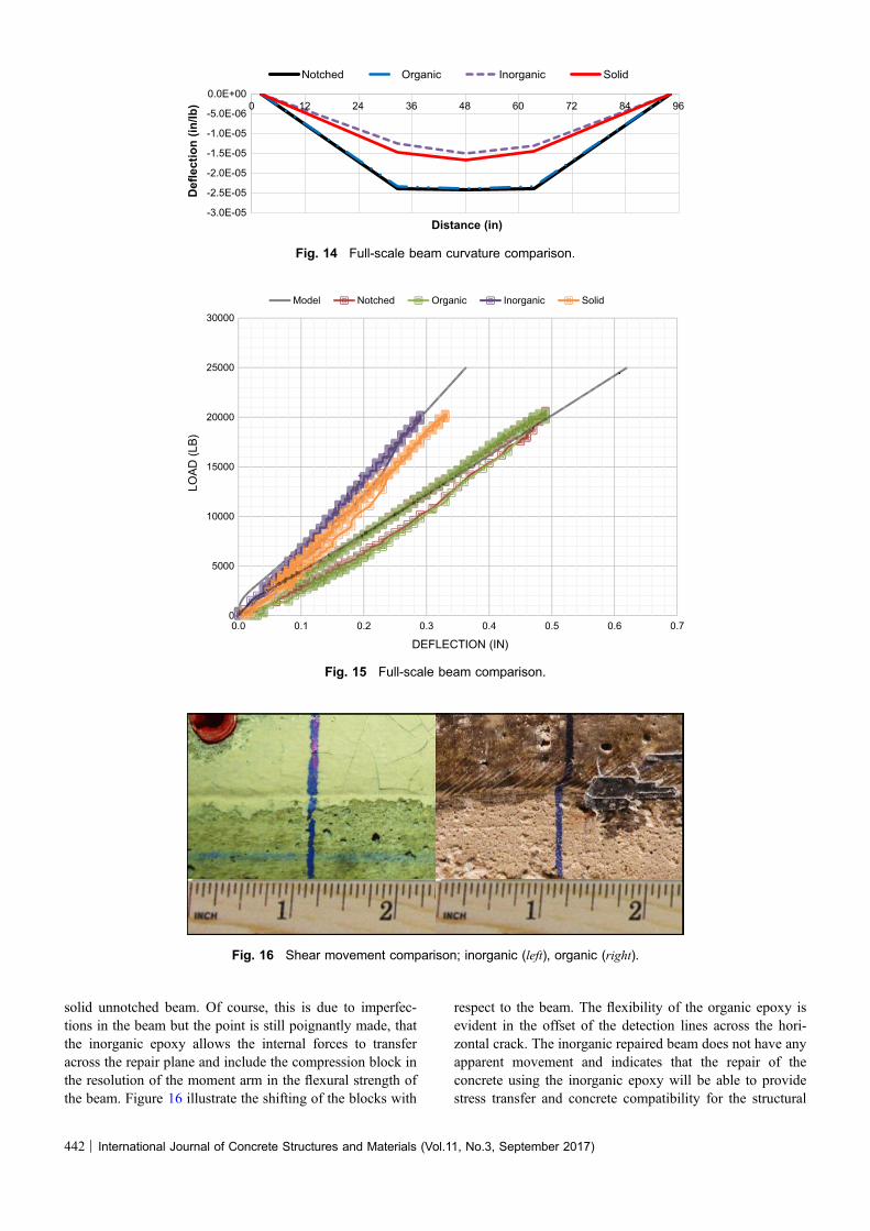
solid unnotched beam. Of course, this is due to imperfec-tions in the beam but the point is still poignantly made, thatthe inorganic epoxy allows the internal forces to transferacross the repair plane and include the compression block inthe resolution of the moment arm in the flexural strength ofthe beam. Figure 16 illustrate the shifting of the blocks with
respect to the beam. The flexibility of the organic epoxy isevident in the offset of the detection lines across the hori-zontal crack. The inorganic repaired beam does not have anyapparent movement and indicates that the repair of theconcrete using the inorganic epoxy will be able to providestress transfer and concrete compatibility for the structural
-3.0E-05
-2.5E-05
-2.0E-05
-1.5E-05
-1.0E-05
-5.0E-06
0.0E+000 12 24 36 48 60 72 84 96
Def
lect
ion
(in/lb
)
Distance (in)
Notched Organic Inorganic Solid
Fig. 14 Full-scale beam curvature comparison.
0
5000
10000
15000
20000
25000
30000
0.0 0.1 0.2 0.3 0.4 0.5 0.6 0.7
LOAD
(LB)
DEFLECTION (IN)
Model Notched Organic Inorganic Solid
Fig. 15 Full-scale beam comparison.
Fig. 16 Shear movement comparison; inorganic (left), organic (right).
442 | International Journal of Concrete Structures and Materials (Vol.11, No.3, September 2017)

element. This will allow that repaired component greaterresistance against additional delamination cracking andprolong the life of the structure.In addition to the experimental evidence of the incom-
patibility of the epoxy repair system and the concrete, boththe notched and epoxy repaired beams featured shearcracking in the outside third of the beam. This indicated thatthe minimum shear reinforcement set by the ACI 318 coderequirement of half the distance from the extreme com-pression fiber to the centroid of the tensile reinforcement wastoo large (ACI (American Concrete Institute) 2011). Inessence, the actual extreme compression fiber was not thetop of the block in the case of the epoxy repaired beam, butthe top of the notch as seen in Fig. 17.
6. Conclusions
The following conclusions can be drawn from this study:
1. The prototype beams showed the feasibility of full-scalebeams for use as effective tests of compatibility of repairmaterials with concrete because of their success on thesmall scale.
2. In prototype testing, the beams repaired with theinorganic material failed at an average of 747 psi andthe beams repaired with the epoxy failed at an averageof 547 psi. The average deflections were 0.0913 inches.
3. The prototype tests indicated that the organic repairsystems were not able to provide the same strengthresistance of the inorganic repaired beams. These testscould not show the range of repair that each systemoffered since no control beams were used.
4. The full-scale beams demonstrated the compatibility ofthe repair system by providing real data on theeffectiveness of the repair material.
5. The inorganic repaired beams featured higher stiffness,no detectible shear slippage along the repair interface,no failure cracking and loading behavior similar to boththe calculated model and the solid unnotched beam.
6. The organic repaired system featured lower stiffness,shear slippage along the repair plane, shear crackingnear the reaction supports indicating decreased depth
from the extreme compression fiber to the centroid ofthe tensile reinforcement, and loading behavior surpris-ingly similar to the notched control beam.
7. Finally, it can be concluded that proposed testingmethodology along with standard testing methods cangreatly help to examine the performance of concreterepair materials. It can also help in the selection ofsuitable materials in terms of compatibility and repairedstructural safety.
Open Access
This article is distributed under the terms of the CreativeCommons Attribution 4.0 International License (http://creativecommons.org/licenses/by/4.0/), which permits unrestricted use, distribution, and reproduction in any medium,provided you give appropriate credit to the original author(s)and the source, provide a link to the Creative Commonslicense, and indicate if changes were made.
References
AASHTO (American Association of State Highway and
Transportation Officials). (2008). Bridging the gap. Wash-
ington, DC: AASHTO.
ACI (American Concrete Institute) Committee 224 report.
(2001). Control of cracking in concrete structures. Farm-
ington Hills, MI.
ACI (American Concrete Institute). (2011). Building code
requirements for reinforced concrete-ACI 318. Farmington
Hills, MI.
Arockiasamy, M. (2000). Evaluation of conventional repair
techniques for concrete bridges. Tallahassee, FL: FDOT
(Florida Department of Transportation).
ASCE (American Society of Civil Engineers). (2017). 2017
Report Card for America’s Infrastructure. Reston, VA.
ASTM (the American Society for Testing and Materials).
(2005). Standard test method for bond strength of epoxy-
resin systems used with concrete by slant shear. ASTM
C882-05, West Conshohocken, PA.
Fig. 17 Shear crack in epoxy repaired beam.
International Journal of Concrete Structures and Materials (Vol.11, No.3, September 2017) | 443

ASTM (the American Society for Testing and Materials).
(2008). Standard test method for flexural strength of con-
crete using simple beam with third-point loading. ASTM
C78-08, West Conshohocken, PA.
ASTM (the American Society for Testing and Materials).
(2013). Standard test method for tensile strength of con-
crete surfaces and the bond strength or tensile strength of
concrete repair and overlay materials by direct tension
(pull-off method). ASTM C1583/C1583 M – 13, West
Conshohocken, PA.
Barbara, S. J., & Wayne, S. F. (1988). Bridge deck hollow plane
repair using injected epoxy. Topeka, KS: KDOT (Kansas
Department of Transportation).
Camille, A. I., & Debs, P. (2007). Experimental study of epoxy
repairing of cracks in concrete. Construction and Building
Materials, 21(1), 157–163.
Chase, S., & Laman, J. (2000). Dynamics and field testing of
bridges. Transportation in The new Millennium: State of
the Art and future Directions, Perspectives from TRB (the
Transportation Research Board Standing) Committees.
Washington, DC.
Davidovits, J. (1991). Geopolymers: Inorganic polymeric new
materials. Journal of Thermal Analysis, 37, 1633–1656.
Do, J. Y., & Kim, D. K. (2012). AHP-based evaluation model
for optimal selection process of patching materials for
concrete repair: Focused on quantitative requirements. In-
ternational Journal of Concrete Structures and Materials,
6(2), 87–100.
Elgabbas, F., Ahmed, E., & Benmokrane, B. (2016). Experi-
mental testing of concrete bridge-deck slabs reinforced with
basalt FRP bars under concentrated loads. ASCE Journal of
Bridge Engineering, 21(7), 04016029.
ElSafty, A., & Abdel-Mohti, A. (2013). Investigation of likeli-
hood of cracking in reinforced concrete bridge decks. In-
ternational Journal of Concrete Structures and Materials,
7(1), 79–93.
FDOT (Florida Department of Transportation). (1999). Bridge
maintenance and repair handbook. Tallahassee, FL: FDOT.
http://www.fdot.gov/maintenance/STR/IN/Maintenance_
and_Repair_Handbook_08-13-11.pdf.
FHWA (Federal Highway Administration). (2009). Annual
Materials Report on New Bridge Construction and Bridge
Rehabilitation: National Bridge Inventory (NBI). Wash-
ington, DC.
Floyd, S. D. (2009). Repairing Bridge Deck Cracks. Epoxy
bonding is an economical solution. Concrete Construction
Magazine. http://www.concreteconstruction.net/products/dec
orative-concrete-surfaces/repairing-bridge-deck-cracks_o.
Garon, R. J. (2000). Effectiveness of high strength composites
as structural and protective coatings for structural elements.
Dissertation. New Brunswick, NJ: Rutgers, the State
University of New Jersey.
Hammell, J. A. (2000). The influence of matrix composition and
reinforcement type on the properties of polysialate com-
posites. Dissertation. New Brunswick, NJ: Rutgers, the
State University of New Jersey.
Iowa Department of Transportation. (2008). Inspection and
acceptance epoxy resins. http://www.iowadot.gov/erl/
archives/2009/oct/IM/content/491.19.pdf.
Krauss, P. D., Rogalla, E. A. (1996). Transverse cracking in
newly constructed bridge decks: NCHRP Report 380.
Washington, DC: Transportation Research Board, National
Research Council.
Labib, E. L., Mo, Y. L., & Hsu, T. T. C. (2013). Shear cracking of
prestressed girders with high strength concrete. International
Journal of Concrete Structures and Materials, 7(1), 71–78.
Leivo, J., Mika, L., Cilaine, V. T., Janne, P., Jessica, R., Erkki,
L., et al. (2006). Sol-gel synthesis of a nanoparticulate
aluminosilicate precursor for homogeneous mullite ceram-
ics. Journal of Materials Research, 21(5), 1279–1285.
Loadstar Sensors. (2016). Software for load sensors. http://
www.loadstarsensors.com/software.html?view=default.
Matthew, K. (2013). Nondestructive repair and rehabilitation of
structural elements using high strength inorganic polymer
composites. Dissertation. New Brunswick, NJ: Rutgers, the
State University of New Jersey.
Matthew, K., Venkiteela, G., Husam, N., & Balaguru., P. N.
(2011). Nanoscale materials for non-destructive repair of
transportation infrastructures. In Proceedings of SPIE 7983,
Nondestructive Characterization for Composite Materials,
Aerospace Engineering, Civil Infrastructure, and Home-
land Security. San Diego, CA.
NCHRP (National Cooperative Highway Research Program)
Synthesis 375. (2007). Bridge inspection practices. Wash-
ington, DC.
NJDOT (New Jersey Department of Transportation). (2007).
Highways carrying bridges in New Jersey. http://www.
state.nj.us/transportation/refdata/bridgereport102007.pdf.
PCA (Portland Cement Association). (1970). Final report:
Durability of concrete bridge decks. Skokie, IL.
Ramseyer, C., & Kang, T. H. K. (2012). Post-damage repair of
prestressed concrete girders. International Journal of
Concrete Structures and Materials, 6(3), 199–207.
Richard, L. E., Balaguru, P. N., Andrew, F., Usman, S., Joseph,
D., & Michel, D. (1997). Fire resistant aluminosilicate
composites. Fire and Materials, 21(1), 67–73.
Rodler, D. J., Whitney, D. P., Fowler, D. W., & Wheat, D. L.
(1989). Repair of cracked concrete with high molecular
weight methacrylate monomers. Polymers in concrete
advantages and applications: ACI SP-116, Farmington
Hills, MI.
SealBoss. (2012). Sealboss 4040 LV Epoxy Resin. Product Data
Sheet, SealBoss Corporation, Santa Ana, CA.
Smoak, W. G. (1996). Guide to concrete repair. Denver, CO:
Bureau of Reclamation.
Soltani, A., Harries, K. A., & Shahrooz, B. M. (2013). Crack
opening behavior of concrete reinforced with high strength
reinforcing steel. International Journal of Concrete Struc-
tures and Materials, 7(4), 253–264.
Soriano, A. (2002). Alternative sealants for bridge decks: Final
report. Pierre, SD: South Dakota Dept. of Transportation
Office of Research.
444 | International Journal of Concrete Structures and Materials (Vol.11, No.3, September 2017)

Stratton, F. W., & McCollom, B. F. (1974). Repair of hollow or
softened areas in bridge decks by rebonding with injected
epoxy resin or other polymers. Topeka: State Highway
Commission of Kansas.
Woo, R. S. C., Honggang, Z., Michael, M. K. C., Christopher,
K. Y. L., & Jang-Kyo, K. (2008). Barrier performance of
silane-clay nanocomposite coatings on concrete structure.
Composites Science and Technology, 68(14), 2828–2836.
International Journal of Concrete Structures and Materials (Vol.11, No.3, September 2017) | 445