Embed Size (px)
Citation preview
Fluid Structure lnteraction Vil l 3
Evaluation of wave energy transmission through a floating breakwater using the SPH method
A. Rueda1, A. J. C. Crespo2 & G. Rodríguez1
1 Departamento de Física, Universidad de Las Palmas de Gran Canaria, Spain 2Environmental Physics Laboratory, Universidad de Vigo, (Campus de Ourense), Spain
Abstract
Energy transmission through a box-shaped floating breakwater (FB) is examined, under simplified conditions, by using the smoothed particle hydrodynamics (SPH) method, a mesh-free particle numerical approach. The efficiency of the structure is assessed in terms of the coefficient of transm ission as a function of the wave period and the location of the floating breakwater relative to the zone to be protected. Preliminary results conceming wave energy transmission reveals a clear improvement of the efficiency as wave period decreases andan important role ofthe bathymetry. Keywords: jloating breakwaters, smoothed partic/e hydrodynamics, wave energy transmission.
1 Introduction
A large number of problems in coastal engineering involve wave-structure interaction processes where wave properties are modified by sorne type of manmade structure. In particular, fixed breakwaters are commonly used to protect coastal facilities, such as harbors, against waves. However, despite such structures successfully protect coastal zones against waves, mainly due to reasons conceming the preservation of the coastal environment and of aesthetic character, there is an increasing strong negative public reaction to the emplacement of classical rubble-mound breakwaters along the coast. This has
WIT Transaclions on The Built Environmenl, Vol 129, O 2013 WIT Press www.wi tpress.com, ISSN 1743-3509 (on-line)
doi : 10.2495/FSI 13002 1
14 Fluid Structure Interaction VII
led engineers to look for more soft and "environment friendly" coastal protection structures.
Floating breakwaters (FB) can provide an altemative coastal protection solution with Iow environmental impact, because its main purpose is to reduce the wave energy transmission to a required leve), providing a dynamic equilibrium ofthe shoreline to preserve existing or artificially nourished beaches, as well as to avoid stagnation zones, by allowing water tlow circulation below their bottom tip and the sea bed. A concise definition of floating breakwater was provided by Hales [ 1 ]: "The basic purpose of any Floating breakwater is to protect a part of shoreline, a structure, a harbar, or moored vesse/s from excessive incident wave energy. Are passive systems; i.e., no energy is produced by the device to achieve wave attenuation. The inciden! wave energy is rejlected, dissipated, transmitted, or subjected to a combination of these mechanisms. The interference of a jloating breakwater with shore processes, bio/ogica/ exchange, and with circu/ation and flushing currents essentia/ for the maintenance of water quality is minima/".
Floating breakwaters can offer a sensitive, low cost, and highly versatile engineering solution, since their location can be varied and their cost is not dependent on the depth of water or the tidal range. Furthennore, they can be used as multi-purpose facilities. FB are commonly used to protect marine structures, marinas and harbors from wave attacks, recent advances has simulated their use in many other fields, such us: coastal and shore line protection, Renewable energy production, Aquaculture, Leisure-Tourism and design facilities from Aquatic sports.
In general, floating breakwaters can be used under a considerable number of geomorphological and oceanographic conditions. Bruce [2] enumerates the following principal advantages: • FB may be the only solution where poor foundations will not support
bottom-connected breakwaters. • FB installations are Iess expensive than rubble-mound breakwaters. • FB presents a minimum of interference with water circulation. • FB is easily moved and can usually be rearranged into new layout with
minimum effort. • FB has a low profile and presents a minimum intrusion on the horizon,
particularly for areas with high tide ranges. However, it is worth noting that floating breakwaters in general, may have
serious disadvantages, with the most significant as follows (Hales [ 1 ]): • The design of a floating breakwater system must be carefully matched to the
site conditions (bottom changes, wind fetch, etc.) with due regard to the longer waves which may arrive from infrequent storms.
• The floating breakwater can fail to meet its design objectives by transmitting a larger wave than can be tolerated without necessarily suffering structural damage.
• A major disadvantage is that floating breakwaters move in response to wave action and thus are more prone to structural-fatigue problems.
WlT Transactions on The Built Environment, Vol 129, © 2013 WIT Press www.witpress.com, ISSN 1743-3509 (on-Iine)
Fluid Structure lnteraction VII 15
Thttre are many different types of FB. An excellent review on this topic was presented by Hales [ 1 ]. Information about more recently developed types of FB can be found in PIANC [15], Tadayon [10], Peña et al. [12] , among others.
Such as commented above, the main purpose of a FB is to reduce the wave energy transmission to a required level without producing a full blockage of the energy approaching the zone of interest. Sorne part of the incident energy is dissipated by damping and friction , as well as through the generation of eddies at the edges of the breakwater. In general, the structure splits incident wave energy - E¡, into transmitted - Et , retlected - En and dissipated energy - Ec1. Thus, a balance of energy flux requires that
(1)
So that dividing both sides of ( 1) by E¡ and taking into account that wave energy is proportional to the wave height squared yields
(2)
where H¡, Ht , Hr and Hd are the incident, transmitted, retlected, and dissipated wave heights, respectively. Equation (2) can be rewritten as
(3)
where Kt , Kn and Kd , are, respectively, the transmission, retlection and dissipation coefficients, given by
K =~~)=He t ...J\°E;J H¡
Kr = ~Er) = Hr ...j\°E;J H¡ (4)
Naturally, optima( results are obtained when transmission is minimized, by maximizing the retlection and dissipation effects. Thus, efficiency of a FB is usually evaluated by meaos ofthe transmission coefficient. During a large period of time, advances of FB behavior and efficiency were achieved almost exclusively by meaos of experimental studies, including both physical models and field experiments, such us: Chen and Wiegel [19] , Torum et al. [14] and Bruce [2].
Since the last decade of the past century numerical simulation studies has increasingly become a common approach to solve very complex problems in the tluid-structure interaction field. Grid or mesh based numerical methods such as the finite difference methods (FDM) and the finite element methods (FEM) have been widely applied to study the interaction between waves and FB (i.e. Williams and Abul-Azm [3] ; Williams et al. [4]).
Despite the success of their use, grid-based numerical methods suffer from difficulties in dealing with free surface problems. Computational mesh-free methods in general, and the smoothed particle hydrodynamics (SPH) method, in particular, alleviate notably these drawbacks. Consequently, it represents an interesting methodology to explore the efficiency of a FB under the action of waves (i.e. Shao [9]).
WIT Transactions on The Buill Environment, Vol 129, © 20 13 WIT Press www.witpress.com, ISSN 1743-3509 (on-line)
16 Fluid Structure Interaction VII
This paper aims to contribute to the existing knowledge on hydrodynamic interaction of waves and floating breakwaters, by exploring the wave energy transmission trough a well-known box-shaped structure Bruce [2] in terms ofthe wave incident period and the relative FB location in relation to the zone to be protected, as well as the effect of the bathymetry, by using the SPH method. In particular the open-source code DualSPHysics (www.dual.sphysics.org) has been used to simulated the ocean waves and FB efficiency.
The paper is structured as follows. Experimental set-up and the basis of SPH methodology are presented in section 2. Preliminary results conceming wave energy transmission trough the type of floating breakwater selected are discussed in section 3. Conclusions are summarized in section 4.
2 Methodology
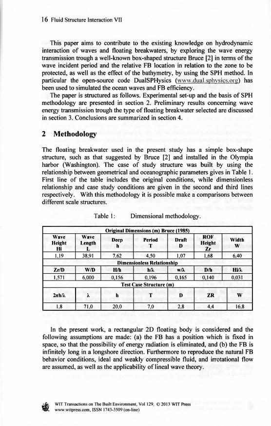
The floating breakwater used in the present study has a simple box-shape structure, such as that suggested by Bruce [2] and installed in the Olympia harbor (Washington). The case of study structure was built by using the relationship between geometrical and oceanographic parameters gives in Table 1. First line of the table includes the original conditions, while dimensionless relationship and case study conditions are given in the second and third lines respectively. With this methodology it is possible make a comparisons between different scale structures.
Table 1: Dimensional methodology.
Orhdnal Dimensions (m) Bruce (1985) Wave Wave
Deep Period Draft ROF Width Height Length Height
Hi L h T D
Zr w
1,19 38 9 1 7,62 4,50 1.07 1.68 640
Dimensionless Relationship Zr/D W/D H/h h/l w/l D/h Hi/l
1,571 6,000 0, 156 0,196 0.165 0,140 0,031
Test Case Structure 1 m)
2nh/l l.. h T D ZR w
1,8 71 ,0 20,0 7,0 2,8 4,4 16,8
ln the present work, a rectangular 20 floating body is considered and the following assumptions are made: (a) the FB has a position which is fixed in space, so that the possibility of energy radiation is eliminated, and (b) the FB is infinitely long in a longshore direction. Furthermore to reproduce the natural FB behavior conditions, ideal and weakly compressible fluid, and irrotational flow are assumed, as well as the applicability of lineal wave theory.
WIT Transactions on The Built Environment, Vol 129, © 201 3 WIT Press www.witpress.com, ISSN 1743-3509 (on-line)
Fluid Structure Interaction VII l 7
2.1 Experimental set-up
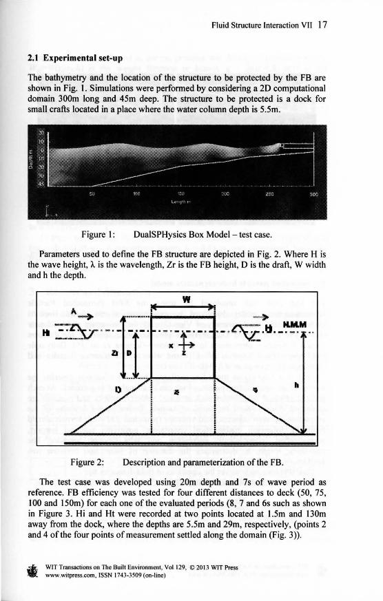
The bathymetry and the location of the structure to be protected by the FB are shown in Fig. 1. Simulations were performed by considering a 20 computational domain 300m long and 45m deep. The structure to be protected is a dock for small crafts located in a place where the water column depth is 5.Sm.
Figure 1: DualSPHysics Box Model - test case.
Parameters used to define the FB structure are depicted in Fig. 2. Where H is the wave height, A. is the wavelength, Zr is the FB height, D is the draft, W width and h the depth.
w
-> ·-~ --t:-· · - ·"\i·'I._~ .. z
Figure 2: Description and parameterization ofthe FB.
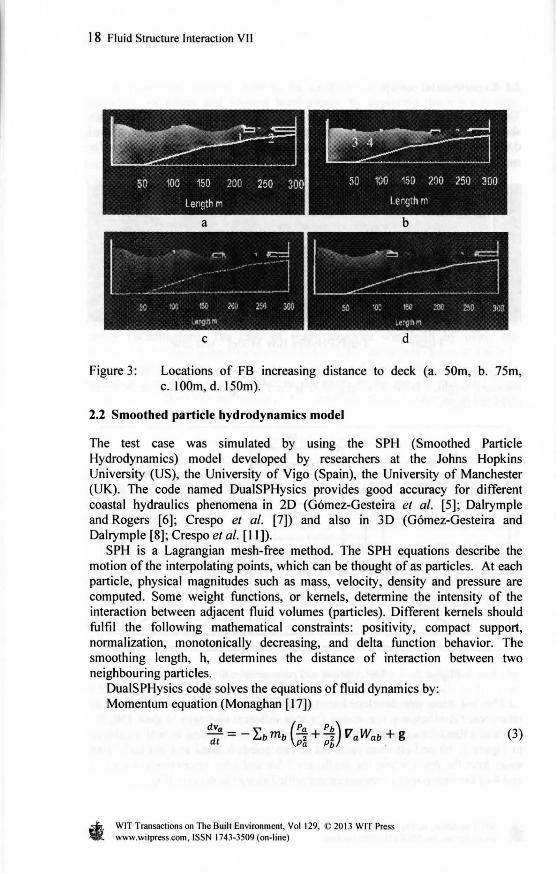
The test case was developed using 20m depth and 7s of wave period as reference. FB efficiency was tested for four different distances to deck (50, 75, 100 and l 50m) for each one of the evaluated periods (8, 7 and 6s such as shown in Figure 3. Hi and Ht were recorded at two points located at l.5m and 130m away from the dock, where the depths are 5.5m and 29m, respectively, (points 2 and 4 ofthe four points ofmeasurement settled along the domain (Fig. 3)).
WIT Transactions on The Built Environment, Vol 129, O 201 3 WIT Press www.witpress.com, ISSN 1743-3509 (on-line)
18 Fluid Structure lnteraction VII
a b
e d
Figure 3: Locations of FB increasing distance to deck (a. 50m, b. 75m, c. IOOm, d. 150m).
2.2 Smoothed particle hydrodynamics model
The test case was simulated by using the SPH (Smoothed Particle Hydrodynamics) model developed by researchers at the Johns Hopkins University (US), the University of Vigo (Spain), the University of Manchester (UK). The code named DualSPHysics provides good accuracy for different coastal hydraulics phenomena in 2D (Gómez-Gesteira et al. [5] ; Dalrymple and Rogers [6]; Crespo et al. [7]) and also in 3D (Gómez-Gesteira and Dalrymple [8] ; Crespo et al. [11]).
SPH is a Lagrangian mesh-free method. The SPH equations describe the motion of the interpolating points, which can be thought of as particles. At each particle, physical magnitudes such as mass, velocity, density and pressure are computed. Sorne weight functions, or kemels, determine the intensity of the interaction between adjacent fluid volumes (particles). Different kemels should fulfil the following mathematical constraints: positivity, compact support, normalization, monotonically decreasing, and delta function behavior. The smoothing length, h, determines the distance of interaction between two neighbouring particles.
DualSPHysics code solves the equations oftluid dynamics by: Momentum equation (Monaghan [ 17])
dva ~ (Pa Pb) V W -d = - L..b mb 2 + 2 a ab + g
t Pa Pb
WIT Transactions on The Built Environment, Vol 129, O 20 13 WIT Press www.witpress.com, ISSN 1743-3509 (on-line)
(3)
Fluid Structure lnteraction VII 19
where v is velocity, Ph and Ph are the pressure and density of particle a and b, W0 6=W(r0 -r1;,h) is the weight function or kernel, g = (0,0,-9.81)ms·2 is the gravitational acceleration.
Continuity equation
(4)
Equation of state (Monaghan [ 17])
(5)
where B is a constant associated with the compressibility module, p0= 1000.0 Kg/m3 the reference density, y is a polytrophic constant, with values from 1 to 7.
2 _ z(p ) _ éJP 1 _ By Co - e o - éJp P=Po - Po (6)
where c0 is the speed of sound at the reference density and the constant B is equal to B = c'fip0 /y .
In these simulations, fluid particles were initially placed on a staggered grid (dx = dz = 0.25 m). A smoothing length, h = 0.45 m, was considered, being the total number of particles np = 121.812. A piston generates waves using theory of Dalrymple and Dean [ 18].
3 Results and discussion
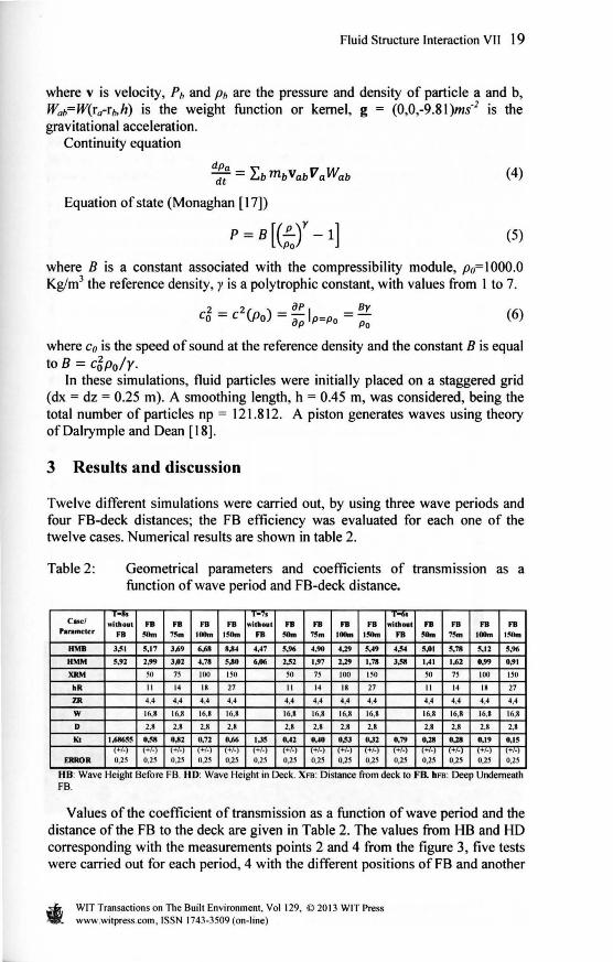
Twelve different simulations were carried out, by using three wave periods and four FB-deck distances; the FB efficiency was evaluated for each one of the twelve cases. Nurnerical results are shown in table 2.
Table 2: Geometrical parameters and coefficients of transmission as a function ofwave period and FB-deck distance.
-, ... , ·1 -11 ,...,,. Cucl .; .. , ... FB FB FB FB •dt•Otl t FB FB FB FB •il•H t FB FB FB FB
Paramctcr FB - 7~ IOlhn l!!Om FB - 75m IOlhn l!!Om FB - 7~m IOlhn l!!Om
HMB J.•1 5,17 J,¡19 6.68 8,11-1 4.'7 5.96 4,90 4.19 M9 4.5-1 5.01 5,78 5.12 5.96
HMM 5.92 2.99 J.02 4.78 5.A-0 6.06 2,52 l,97 2.19 1.78 J,58 IAI l,¡11 0.99 0.91
XRM so 7S 100 ISO so 7l 100 ISO SO 7l 100 ISO
•R 11 14 18 27 11 14 18 27 11 14 18 27
lJI 4.4 4.4 4.4 4.4 4.4 4,4 4,4 4,4 4,4 4,4 4,4 4,4
w 16.R 16.8 16.8 16.8 16.8 16.8 16.8 16,8 16.8 16,8 16.8 16,8
D 2.8 2.8 2.8 2,8 2,8 2,8 2.8 2.8 2,8 2,8 2,8 2,8
lú IM655 º-~ U2 0,72 0,¡16 l.J5 OA2 º"° 0.!'J O,J2 0,79 0,111 0,111 0,19 o.is 1+1.¡ 1+1-¡ 1+1·) 1+1.¡ 1+1·1 \+/·) \+/·) \+/·) l+I•) 1+1-¡ 1+1·) 1+1-¡ 1+1-1 \+/-) 1+1-¡
ERROR 0.2S 0.2l 0.2S 0.2S 0.2l 0.2S 0.2S 0.2S 0.2S 0,2S o.is 0,2l O.H 0.2S 0.2S
HB: Wave He1ght Befo re FB. HD: Wave He1ght m Deck. Xra: D1stance from deck to FB. hra: Deep Undemeath FB.
Values ofthe coefficient oftransmission as a function ofwave period and the distance of the FB to the deck are given in Table 2. The values from HB and HD corresponding with the measurements points 2 and 4 from the figure 3, five tests were carried out for each period, 4 with the different positions of FB and another
WIT Transactions on The Built Environment, Vol 129, O 20 13 WlT Press www.witpress.com, ISSN 1743-3509 (on-Iine)
20 Fluid Structure lnteraction VII
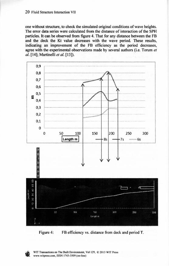
one without structure, to check the simulated original conditions ofwave heights. The error data series were calculated from the distance of interaction of the SPH particles. lt can be observed from figure 4. That for any distance between the FB and the deck the Kt value decreases with the wave period. These results, indicating an improvement of the FB efficiency as the period decreases, agree with the experimental observations made by several authors (i.e. Torum et al. [14]; Martinelli et al. [13]).
~
0,9
0,8
0,7
0,6
0,5
0,4
0,3
0,2
0,1
o
1 1 1- t-.. ·-
' '
~---·-·······-·--
' ' &----+-------!- --------! : ! "'
300
' ' ' r-----------;---. - :- - t--1 1 1 1 ' : : : : 1 1 1 1 ----·-.. -t_,,_ ·--··---:···- - :-·--· ···------• : 1 f 1 • 1
1 +-~--t·------1 1 1 1 : : : ;
----t::::::;~;;r.r -¡---·1··----------·----• 1 1 1 1 1 t 1
! ··-·-----·------1---·-·--•--•- --'--·-····-·-·--···
L______ j _____ ¡ _J_ __ j ______________ _ ' ' ' ' ' '
150 ! !200 ! ' ' ' ' ' ' -+Bs! -+7s - 6s ' ' '
50 100
llength m 1
250 o
: : ! : : ::: ! t ' 1 1, ' '
1, ' 1 ,:/
'-V '-V V
Figure 4: FB efficiency vs. distance from deck and period T.
WIT Transactions on The Built Environment, Vol 129, O 2013 WIT Press www.witpress.com, ISSN 1743-3509 (on-Iine)
Fluid Structure lnteraction VII 21
The pattern of variation for the coefficient oftransmission as a function ofthe distance between the FB position and the deck, for a given period, is clearly more complex. For a wave train of 6s period, the efficiency is considerably high but undergoes a relative decrease as the FB approaches to the deck, especially between 100 and 75 m. However, while the value of Kt exhibits a similar increasing behavior for the cases of 7s and 8s for large distances, it changes drastically for shorter distances, with a relative increase of the transmitted wave height. Preliminary results in this sense indicate that these changes in Kt with the distance could be related to the reduction ofthe water depth below the FB tipas it is displaced towards the coast and to the associated shoaling effect. However, a confirmation of these results require the analysis of additional simulations with simpler bathymetric conditions (constant slope), which are being carried out.
4 Conclusions
The efficiency of a box-shaped tloating breakwater is examined in terms of the period ofthe incident wave train and by varying the distance between the FB and the structure to be protected. The efficiency of the FB increases as the period of the incident wave decreases, independently of the distance between the FB and the deck. The efficiency of the FB tends to get worse as the distance between both structures reduces. However the observed patterns of variation in this case are considerably more complex.
Acknowledgements
This research work was carried out under support and collaborations of the Colombian Navy, The University of the Las Palmas de Gran Canaria, the Environmental Physics Laboratory from the University of Vigo and the Foundation Carolina, Spain.
References
[I] Hales, Z.L. , Floating Breakwaters: State of the Art, U.S Army Corps of Engineers. Technical Report No 81-1 Cap. 1. pp. 23-45, 1981.
[2] Bruce, L., Floating Breakwater Design, J. Waterway, Port, Coastal, Ocean Eng. 111 , pp. 304- 318, 1985.
[3] Williams A.N., and Abul-Azm A.G., Dual pontoon tloating breakwater. Ocean Engineering. 24(5), pp. 465-78, 1997.
[4] Williams, A., N. , Lee, H.S., and Huang, Z. , Floating pontoon breakwaters. Ocean Engineering. 27, pp. 221 - 240, 2000.
[5] Gómez-Gesteira, M., D. Cerqueiro, A.J.C. Crespo and R.A. Dalrymple. Green water overtopping analyzed with a SPH model. Ocean Engineering, 32, pp.223- 238, 2005.
[6] Dalrymple, R. A., Rogers, B., Numerical modeling ofwater waves with the SPH method. Coastal Engineering, 53, pp. 141-147, 2006.
WIT Transactions on The Built Environment, Vol 129, © 20 13 WIT Press www.witpress.com, ISSN 1743-3509 (on-line)
22 Fluid Structure Interaction VII
[7] Crespo, A.J.C., Gómez-Gesteira, M. , Dalrymple, R.A., Modeling Dam Break Behavior over a Wet Bed by a SPH Technique. Journal of Waterway, Port, Coastal, and Ocean Engineering, 134(6), pp. 313-320, 2008.
[8] Gómez-Gesteira, M. , Dalrymple, R.A., Using a three-dimensional smoothed particle hydrodynamics method for wave impact on a tall structure, Journal of Waterway, Port, Coastal and Ocean Engineering, 130(2), pp. 63-69, 2004.
[9] Shao, S., SPH simulation of a solitary wave interaction with a curtain-type breakwater. Journal of Hydraulic research, 43 (4), pp. 366--375, 2005.
[10] Tadayon, N., Effect of geometric dimensions on the transmission coefficient of tloating breakwaters. lnternational Journa/ of Civil and Structural Engineering, 1 (3), pp. 775-781 , 201 O.
[11] Crespo, A.J.C. , Gómez-Gesteira, M. y Dalrymple, R.A., 30 SPH simulation of large waves mitigation with a dike. Journal of Hydraulic Research, 45(5), pp. 631-642, 2007a.
[12] Peña, E., Ferreras, J. , and Sanchez-Tembleque, F., Experimental study on wave transmission coefficient, mooring lines and module connector forces with different designs of tloating breakwaters. Ocean Engineering, 38, pp. 1150-1160, 2011.
[13] Martinelli, Luca, Piero, Ruol, Zanuttigh, Barbara, Wave basin experiments on floating breakwaters with different layouts. App/ied Ocean Research, 30, pp. 199-207, 2008.
[14] Torum, A. , Stansberg, C.T., Otterá, G.O., Sláttelid, O.H., Model tests on the CERC full scales test tloating breakwater, final report, AD-A204 145. United States Arrny. 1987.
[ 15] Perrnanent Intemational Association of navigation Congress - PIANC, Floating Breakwaters: A Practical Guide for Design and Construction. Report of working group No 13 of the perrnanent technical committee 11 , 1994.
[ 16] Monaghan, J. J. , Smoothed Particle Hydrodynamics. Annual Rev. Astron. App/., 30, pp. 543-574, 1992.
[17] Monaghan, J. J., Simulating free surface tlows with SPH. Journal Computational Physics, 11 O, pp. 399--406, 1994.
[ 18] Dalrymple, R.A., and Dean, R.G., The spiral wavemaker for littoral drift studies, Proc. l 31
h Conf. Coastal Eng. ASCE, 1972. [ 19] Chen, K., Wiegel, R.L., Floating breakwater for reservoir marines. Proc. of
the Twelfth Coastal Engineer. pp. 487-506, 1970.
WIT Transactions on The Built Environment, Vol 129, O 201 3 WIT Press www.witpress.com, ISSN 1743-3509 (on-line)