Embed Size (px)
Citation preview
Executive Summary
Dr. Randy Zelick, PSU Biology department, has requested the design of a flow
tank to aid in the testing of specific species of tropical fish. The main criteria of the
design, is to obtain a fully developed, laminar and simulated stream flow that is capable
of reaching velocities up to 20 cm/s. The design is constrained mainly by flow channel
size, cost, and materials.
To aid in the brainstorming method an internal and external search was
performed. The internal search focused on intellectual ideas that would assist in the
design selection process. Colleagues of the sponsor in Germany have already created a
limited flow tank channel that lacked a flow altering device to study the fish response to
flow orientation. The tank, however, set a baseline for the design team on what the
sponsor was looking for.
External searches were performed to discover new products that might be used, as
well as to get material specifications and pricing information so that the design
constraints were kept. This search includes a holding reservoir capable of sustaining the
constant flow needed to perform the experiment, as well as being constructed from a
material deemed safe to hold the treated water and prevent fish poisoning. The channel
flow tank will be constructed due to the customized nature of the project.
The selection process involved 3 different models that were scored with a
weighted value. The chosen reservoir was the 55 gallon barrels due to the food grade
material they are constructed of and the inexpensive financial impact on the rest of the
project budget. The flow tank testing channel will be of a piped in type design as
opposed to a complete channel flow design. This will allow for higher flow rates, while
maintaining the sponsors’ conditions of fully developed and laminar flow.
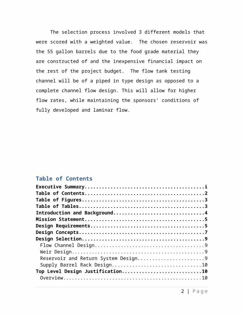
Table of ContentsExecutive Summary............................................................................................................iTable of Contents...............................................................................................................2Table of Figures..................................................................................................................3Table of Tables...................................................................................................................3Introduction and Background..........................................................................................4Mission Statement..............................................................................................................5Design Requirements.........................................................................................................5Design Concepts.................................................................................................................7Design Selection..................................................................................................................9
Flow Channel Design.......................................................................................................9Weir Design......................................................................................................................9Reservoir and Return System Design...............................................................................9Supply Barrel Rack Design............................................................................................10
Top Level Design Justification........................................................................................10Overview........................................................................................................................10Flow Channel Geometry................................................................................................10Adjustable Weir..............................................................................................................12Reservoir System............................................................................................................15
Acknowledgements..........................................................................................................16Works Cited......................................................................................................................17Appendices........................................................................................................................18
Appendix A: Moody Diagram........................................................................................18............................................................................................................................................Appendix B: Weir Design Proportions..........................................................................19Appendix C: Experimental Raw Data............................................................................20Appendix D: Bill of Materials (BOM)...........................................................................22Appendix E: Detailed Drawings....................................................................................23
2" Coupling.................................................................................................................232" Valve......................................................................................................................234" to 2" Coupling Reducer.........................................................................................246" to 4" Coupling Reducer.........................................................................................24Flow Channel..............................................................................................................25Weir Body..................................................................................................................25Adjustable Weir Gate.................................................................................................26Turn Table Channel Cradle........................................................................................27Turn Table Channel Cradle Stress Analysis...............................................................27Turn Table Base.........................................................................................................28Turn Table Base Stress Analysis................................................................................28Turn Table..................................................................................................................28Reservoir Stand..........................................................................................................29
Appendix F: Equations...................................................................................................30Appendix G: Pump Selection.........................................................................................31Appendix H: PDS Adherence........................................................................................32Appendix I: Flow Analysis............................................................................................33Appendix J: Assembly Drawings...................................................................................34
2 | P a g e
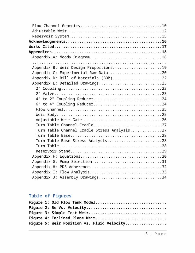
Table of FiguresFigure 1: Old Flow Tank Model.........................................................................................Figure 2: Re Vs. Velocity.....................................................................................................Figure 3: Simple Test Weir.................................................................................................Figure 4: Inclined Plane Weir.............................................................................................Figure 5: Weir Position vs. Fluid Velocity.........................................................................Figure 6: Guillotine Weir (Final Design)...........................................................................Figure 7: Moody Diagram...................................................................................................Figure 8: Weir Design Proportions....................................................................................Figure 9: 2” Coupling Drawing..........................................................................................Figure 10: 2” Valve Drawing..............................................................................................Figure 11: 4” to 2” Coupling Reducer Drawing...............................................................Figure 12: 6” to 4” Coupling Reducer Drawing...............................................................Figure 13: Flow Channel (Final Design)............................................................................Figure 14: Guillotine Weir Body (Final Design) Drawing...............................................Figure 15: Guillotine Adjustable Weir Gate (Final Design) Drawing............................Figure 16: Turn Table Channel Cradle Drawing (Final Design)....................................Figure 17: Stress Analysis of Turn Table Channel Cradle..............................................Figure 18: Turn Table Base (Final Drawing)....................................................................Figure 19: Stress Analysis of Turn Table Base.................................................................Figure 20: Turn Table Drawing (Final Design)................................................................Figure 21: Reservoir Stand Drawing (Final Design)........................................................Figure 22: Pump Curve.......................................................................................................Figure 23: Fluid Flow Analysis...........................................................................................Figure 24: Collapsed/Exploded Assembly of Flow Channel (Final Design)...................Figure 25: Collapsed/Exploded Assembly of Turn Table (Final Design).......................
Table of TablesTable 1: Summary of PDS...................................................................................................Table 2: Water Delivery/Recover System PDS Requirements........................................Table 3: Flow Channel System PDS Requirements..........................................................Table 4: Cradle and Turn Table PDS Requirements.......................................................Table 5: Wooden Weir Raw Data.......................................................................................Table 6: Inclined Weir Raw Data.......................................................................................Table 7: Bill of Materials (BOM).......................................................................................Table 8: PDS Adherence.....................................................................................................
3 | P a g e
Introduction and Background
This design project is an outgrowth of several existing flow tank designs. These
tanks are used to test the response of neurological reactions in fish to the changes in
stream flow rate. The redesign of the flow tank was requested by our client, Professor
Randy Zelick of the Portland State University biology department. The previous designs
for flow tanks were circular
and had some kind of motor
inserted into the tank to
simulate stream flow. The
previous designs used a
spinning propeller to drive
water around the tank. The
motor created a detectable
electrical frequency that testing probes transferred to recording equipment. Some other
results of using propellers were that a harmonic vibration was created in the water and the
flow was turbulent. Our team was given the opportunity to design a tank that did not use
a motor to propel water and
preferably minimize flow
turbulence within the testing region.
The redesign criteria given to us included specific details. During testing the fish
must remain static with the minimum vibration possible. This is critical because a small
electrode is inserted into the fish brain. Any movement could dislodge the probe and the
test would have to be rerun. The flow is required to be laminar, or as close to laminar as
possible, while having an adjustable velocity between 0 to 20 cm/s (Blake, 2007). The
flow channel and/or the water flow will be designed to be adjustable to ±15° from the
centerline of the fish (Braithwaite, 2003). The adjustability is used in testing the neural
response to changes in flow direction. The water is treated to sustain fish life and
subsequently should be recycled to the reservoir for future tests. Finally the testing
4 | P a g e
Figure 1: Model of current flow channel being used in Bonn, Germany
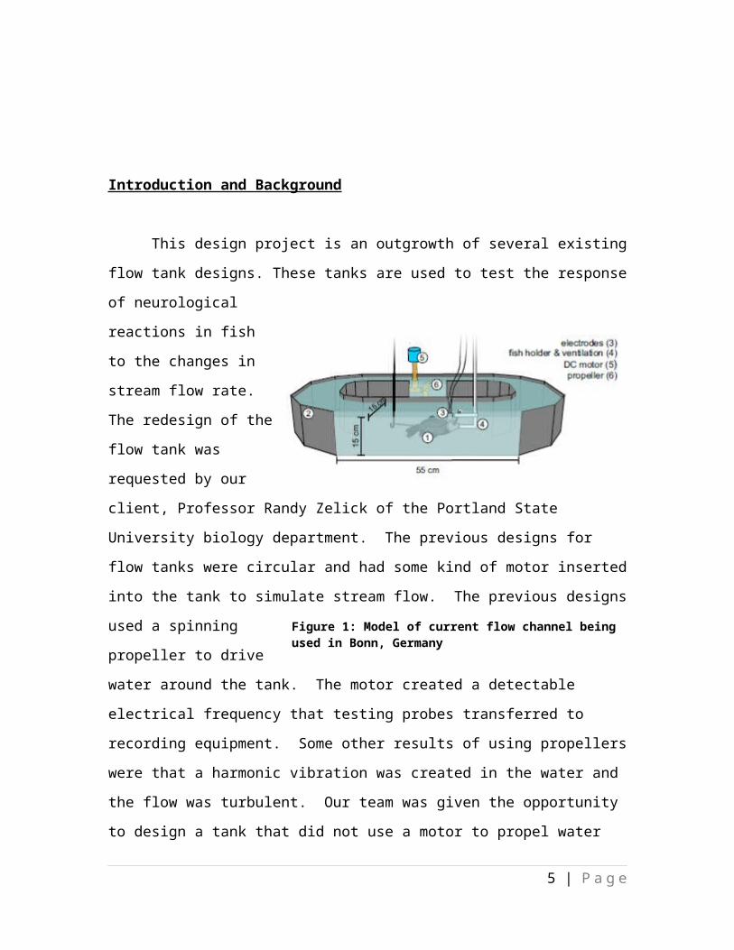
equipment will be required to allow mounting as close to 90° above the fish as possible,
all while staying within a $600 budget. The testing equipment includes the electrode
assembly, a microscope, the fish holder, and an ultrasonic vibrator.
A linear tank design was found to be the simplest and most cost effective design
compared to a circular tank. The tank design consists of an elevated reservoir with a
piping system that flows into the testing channel. The water in the flow channel runs
close to laminar flow, as requested. The flow is straightened as it approaches the fish by
diffusers so the fish feels laminar water flow. The piping has a set of swivel couplers that
allow the flow from the pipe to be aligned at angles to the fish. The channel will be
designed so that steady flow occurs in the tank while testing is conducted. Final sizing of
the channel was not specified. The maximum size of the piping is constrained to no more
than four inch diameter tubing. The system will be designed to accept calibration
instruments and leave room for additional instrumentation to be added as required.
Mission Statement
The project is to design a flow tank used by PSU biologists to test fish neuron
responses from the lateral line sensory organs. It is predicted that specific neurons fire in
response to the angle and velocity (speed) of water flow, but this has not been shown.
The tank will have the capabilities of a variable water flow speed and variable flow angle.
The ideal flow tank design will allow constant laminar flow, adjustable flow rate and
angle, vibration minimization, portability, and static control over fish so that sensory
organs remain under water without full submersion. Completion of the project will be in
June of 2010.
Design Requirements
Specifications for the flow tank redesign were provided to the project team by the
sponsor Dr. Randy Zelick. These specifications were based off the current design already
in use by Dr. Zelicks’ collegues in Bonn Germany. These requirements have been
categorized in Table 1 on the following page.
5 | P a g e
Table 1 Summary of Product Design Specifications
*** - High Priority ** - Medium Priority * - Low PriorityPriority Requirement Metric TargetPerformance
*** Minimal Frequency Interference - 0*** Fluid Flow - Laminar*** Minimum Flow Velocity cm/s 20*** Maximum Flow Velocity (min) cm/s 40** Test Duration s 30
Environment* Resistant To Oxidation yes/no yes** Cost To Produce $ 600
Size and Shape*** Fish Holding Tank Depth (static flow) cm ~7.5
** Rotation of TankAngle (positive or negative degrees) 15
Maintenance* Off-The-Shelf Parts yes/no yes
* Ease of RepairPeople Required to
Fix 1* Life In Service years 5
Installation** Fits On Existing Air Table yes/no yes
**Does not Interfere With Testing Equipment yes/no yes
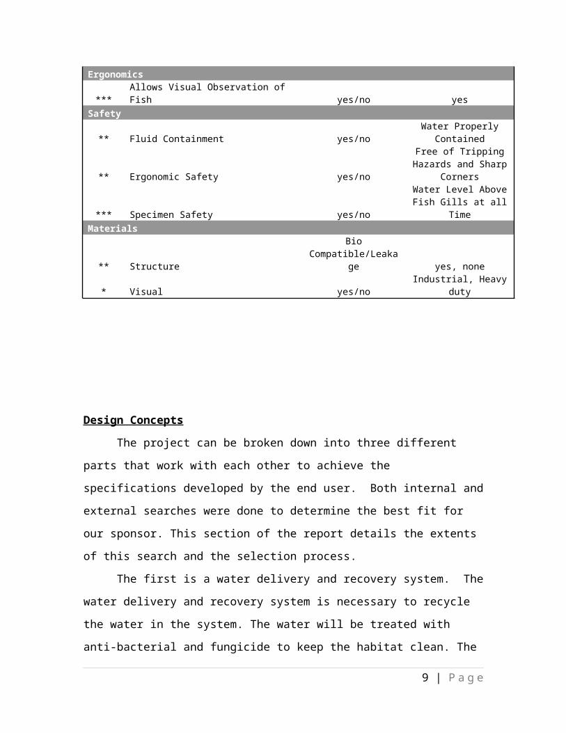
Ergonomics*** Allows Visual Observation of Fish yes/no yes
Safety
** Fluid Containment yes/noWater Properly
Contained
** Ergonomic Safety yes/no
Free of Tripping Hazards and Sharp
Corners
*** Specimen Safety yes/noWater Level Above Fish
Gills at all TimeMaterials
** StructureBio
Compatible/Leakage yes, none* Visual yes/no Industrial, Heavy duty
6 | P a g e
Design Concepts
The project can be broken down into three different parts that work with each
other to achieve the specifications developed by the end user. Both internal and external
searches were done to determine the best fit for our sponsor. This section of the report
details the extents of this search and the selection process.
The first is a water delivery and recovery system. The water delivery and
recovery system is necessary to recycle the water in the system. The water will be treated
with anti-bacterial and fungicide to keep the habitat clean. The water will pumped back to
the upper reservoir after spilling through the gravity fed channel so that another test can
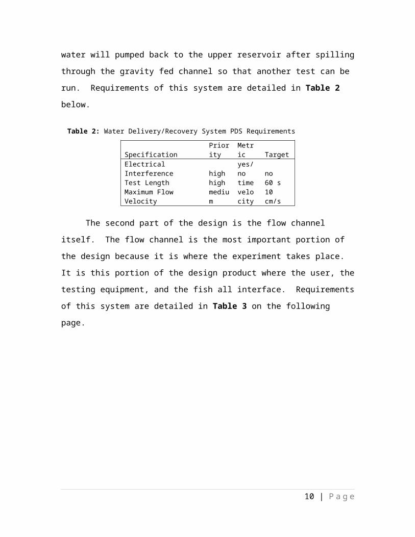
be run. Requirements of this system are detailed in Table 2 below.
Table 2: Water Delivery/Recovery System PDS Requirements
Specification Priority Metric Target
Electrical Interference highyes/no no
Test Length high time 60 s
Maximum Flow Velocitymedium
velocity 10 cm/s
The second part of the design is the flow channel itself. The flow channel is the
most important portion of the design because it is where the experiment takes place. It is
this portion of the design product where the user, the testing equipment, and the fish all
interface. Requirements of this system are detailed in Table 3 on the following page.
7 | P a g e

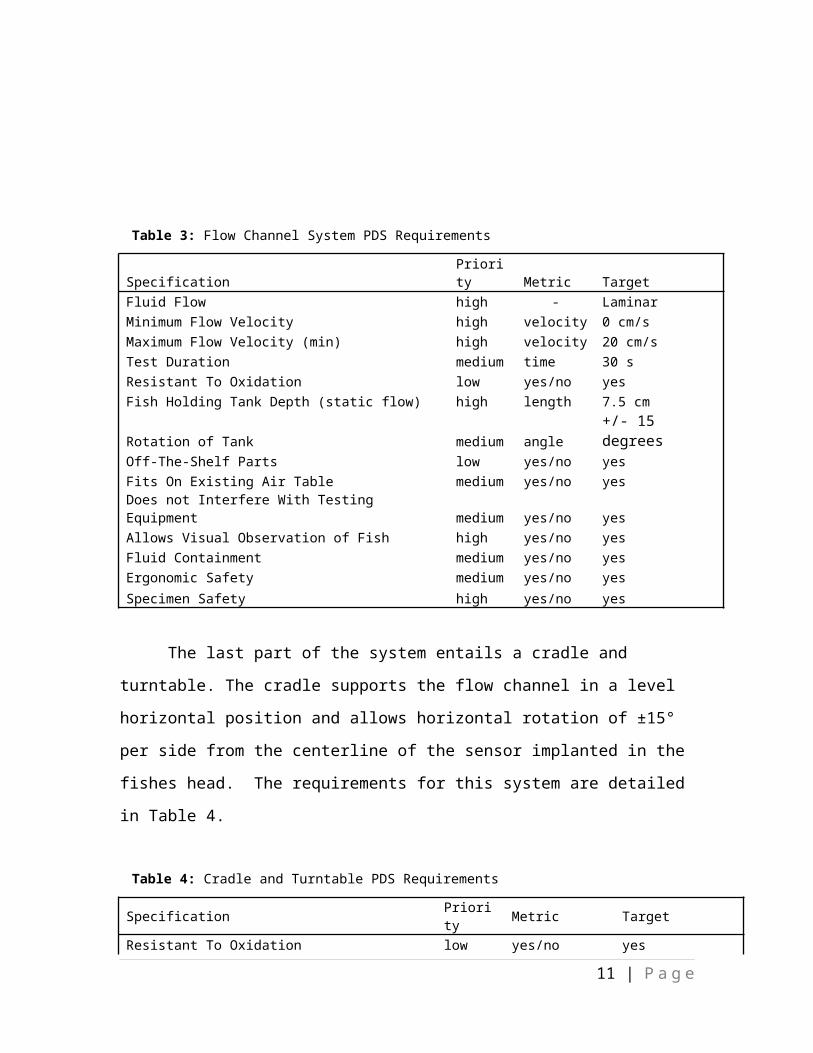
Table 3: Flow Channel System PDS Requirements
Specification Priority Metric TargetFluid Flow high - LaminarMinimum Flow Velocity high velocity 0 cm/sMaximum Flow Velocity (min) high velocity 20 cm/sTest Duration medium time 30 sResistant To Oxidation low yes/no yesFish Holding Tank Depth (static flow) high length 7.5 cmRotation of Tank medium angle +/- 15 degreesOff-The-Shelf Parts low yes/no yesFits On Existing Air Table medium yes/no yesDoes not Interfere With Testing Equipment medium yes/no yesAllows Visual Observation of Fish high yes/no yesFluid Containment medium yes/no yesErgonomic Safety medium yes/no yesSpecimen Safety high yes/no yes
The last part of the system entails a cradle and turntable. The cradle supports the
flow channel in a level horizontal position and allows horizontal rotation of ±15° per side
from the centerline of the sensor implanted in the fishes head. The requirements for this
system are detailed in Table 4.
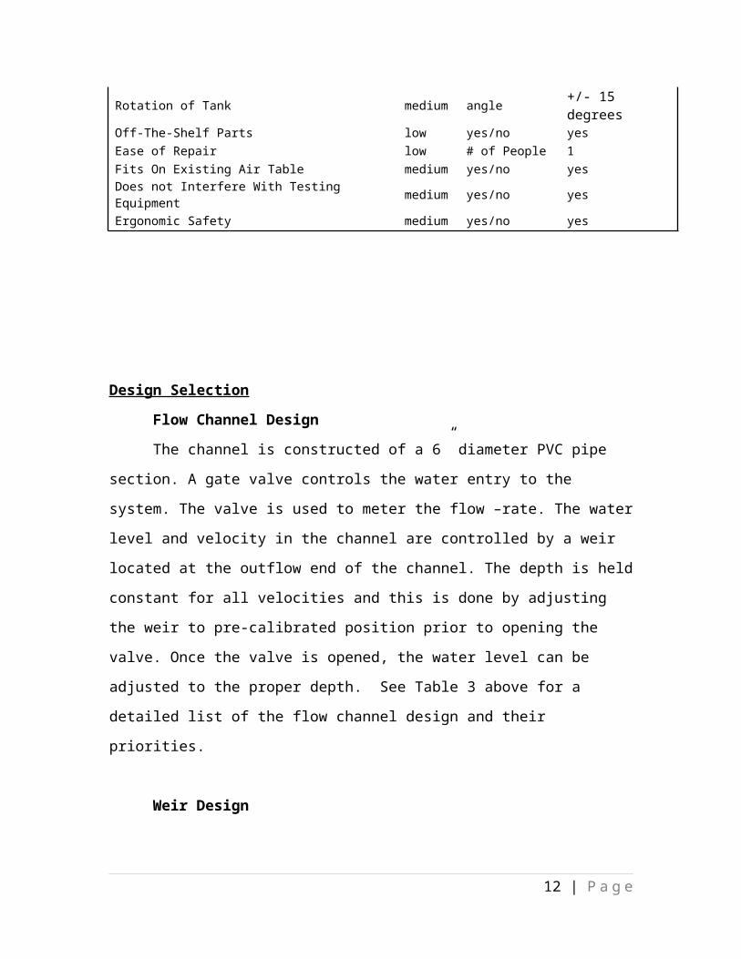
Table 4: Cradle and Turntable PDS Requirements
Specification Priority Metric TargetResistant To Oxidation low yes/no yesRotation of Tank medium angle +/- 15 degreesOff-The-Shelf Parts low yes/no yesEase of Repair low # of People 1Fits On Existing Air Table medium yes/no yesDoes not Interfere With Testing Equipment medium yes/no yesErgonomic Safety medium yes/no yes
8 | P a g e
Design Selection
Flow Channel Design
The channel is constructed of a 6” diameter PVC pipe section. A gate valve
controls the water entry to the system. The valve is used to meter the flow –rate. The
water level and velocity in the channel are controlled by a weir located at the outflow end
of the channel. The depth is held constant for all velocities and this is done by adjusting
the weir to pre-calibrated position prior to opening the valve. Once the valve is opened,
the water level can be adjusted to the proper depth. See Table 3 above for a detailed list
of the flow channel design and their priorities.
Weir Design
The weir design is a simple gate style system that is held inside a sealed
rectangular box frame. The weir gate slides up and down between seals to prevent water
loss prior to test starts. The gate is indexed with specific velocities so that they can be
preset. This allows the tester to concentrate on the level of the water only. The weir is
installed at the end of the flow channel where it can spill out into the return reservoir. The
illustration shown below represents the weir design used for the system.
Reservoir and Return System Design
The reservoir and return tanks are food grade 55 gallon polyurethane barrels. The
inlet supply side barrel lays horizontally supported on a steel rack designed to hold the
outlet three feet above the channel centerline. The water is gravity fed to the channel. The
horizontal positioning of the barrel allows the least variance in velocity for the longest
time span. The return reservoir is positioned vertically at the outlet of the channel. The
water is returned to the elevated supply tank by a 3900 gallon per hour (69 gal/min) sump
pump through a 1.5 inch PVC pipe. There is a 15 foot head loss from the pipe, elbows,
couplers and fittings.
9 | P a g e
Supply Barrel Rack Design
The water for the flow channel is supplied by an elevated barrel. The barrel lays
horizontally on a 10 gage metal cabinet rack. The rack keeps the inlet water 3 feet above
the entry to the flow channel. The overall elevation of 6 feet at the outlet of the barrel
allows for a wide velocity range in the flow rates. The target velocities range from 0 cm/s
up to 20 cm/s, without reaching turbulent conditions.
The rack used is sturdy enough to carry more weight than the two 55 gallons (860
lbs.) of water. The initial design employed two55 gallon barrels so constant flow can be
maintained for longer than thirty seconds in the 20 cm/s. A single barrel was determined
to supply a flow of 20 cm/s for 35 seconds without a significant loss of velocity. A
second barrel can be added later if longer flow time periods are needed.
The stress on the horizontal end rails is 573 psi assuming a point load of half the
total weight of the barrels. This is far below the average published values for carbon steel
of 20.0 ksi (LETCO Ind). This gives a factor of safety of 35. The legs of the rack have a
stress of 287 psi per leg.
The stress equation is of the form:
PA
=σ (Equation 1 from Appendix F)
Top Level Design Justification
Overview
At the beginning of our project, the main criteria of the flow channel design was
to obtain fully developed laminar fluid flow that would simulate stream flow capable of
reaching velocities up to 20 cm/s. Client also desired flow channel to be compatible with
biological research tools including a microscope, electrode with signal amplifier, actuator
that calibrates vibrations, and fish holding shelf with respirator. Prototype components
for analysis included flow channel, control weir, and fluid reservoir system
Flow Channel Geometry
10 | P a g e
Initial design specifications were slightly adjusted to comply with fluid conditions
inside the flow channel during operation. Original customer requirement for laminar
flow was modified to allow wider range of fluid velocities during operational procedure.
Spatial restrictions governed by interfacing equipment limits the overall foot-print our
designed product is permitted. Several biological research tools like microscopes,
electrode with signal amplifier, calibrating vibrator, and fish respirator has precedence in
access to fish and channel operation must not hinder integrated equipment. Additional
restrictions on channel geometry included a 3-ft by 3-ft isolating air table in which the
interfaced equipment is oriented and the channel is mounted on the support frame.
Consideration of spatial variables, manufacturing costs, and a velocity profile with
minimal variation across the channel’s cross-sectional area influenced the parametric
shape of the designed flow channel. A comparison between cross-sectional geometries
and flow conditions was done using a plot, Figure 2, of Reynolds Number versus fluid
flow velocities for three different shapes.
Figure 2: Represents the bulk velocity behavior within different cross-sectional geometries having equal wetted areas.
11 | P a g e
Evaluating flow condition as a function of channel geometry using the previous
figure provides clarification that a triangular cross-sectional area is best scenario for
limiting the onset of turbulance. Though turbularnt flow is undesirable the velocity
profile is least variable from the streamline center to channel wall surface. Completely
eliminating turbulance at velocities greater than 10 cm/s can not be accomplished due to
the requirement of a rotational channel and maintaining that the test specimen remains
unobstructed by the channel’s wall surface. To help mitigate any rotational obstruction
or interference with existing operational equipment the overall channel length was
restricted to 40-inches. Continued analysis shows that circular flow areas demonstrate
smooth velocity profiles and offer minimal frictional losses along the radial perimeter.
Without flow sensing equipment to measure fluid velocity or pressure change in
the streamline, a velocity profile with minimal variation across channel area is optimal.
Introducing gradual expansion diffusers from 2-inch ID to 6-inch ID provided better
steady-state flows entering the operational test area of the channel. Consequently, an
optimal entrance length of six times ID (L = 6*(ID)) is restricted and the use of gradual
expansion diffusers and upstream flow collimators better conditioned entering fluid flow.
Additionally, manufacturing cost were severly compromised by alotted budget and
become the design team’s responsibility. Fully developed flow, consistent fluid velocity
profile, and cost specifications coupled together helped propogate the decision to select a
circular flow channel with 6-inch nominal ID rigid PVC pipe.
Adjustable Weir
Development of weir control to
enable changes in fluid velocity while
holding a constant instantaneous fluid
volume within the flow channel was
considered throughout the detailed design
process. A gate valve was selected to
12 | P a g eFigure 3: Simple weir design to test flow channel performance at various fluid velocities.
control inlet flow-rates and provides best adjustability to maintain consistent fluid
volume inside the flow channel at different weir heights. It was decided the inlet flow
adjustment would be used to match the outlet flow weir condition and help keep fluid
volume inside channel generally constant, allowing for small transient response to occur
when fluid velocity changes and a minimal decrease in fluid volume. An increase in
water volume above the steady-state datum is detremental to channel effectiveness and
proves useless. Adjustment of weir must preceed gate valve adjustment in order to
prevent volume overflow inside the flow channel. To ensure constant fluid volume was
indeed acheivable with variable weir heights and an adjustable gate valve, initial
experimental tests were conducted using a semi-perminant wooden weir with
interchangable plastic gates varying in height.
Experiments using a removable semi-circular wooden weir with 2” rectangular
cut from center initially started empirical process. Clear plastic inserts enabled variable
speed experimentation with steady channel volume to occur. Results considered with
admiral promise as adjustable-weir design targets specifications. Figure 3 is a simple
representation of the initial weir design used to test our assumption that constant fluid
depth could be controlled by adjusting inlet gate valve in correlation with the weir. The
observed experiments provided conclusive evidence that a constant volume condition is
satisfied for the duration of time required for flow channel operation.
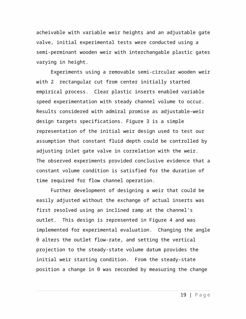
Further development of designing a weir that could be easily adjusted without the
exchange of actual inserts was first resolved using an inclined ramp at the channel’s
outlet. This design is represented in Figure 4 and was implemented for experimental
evaluation. Changing the angle θ alters the outlet flow-rate, and setting the vertical
projection to the steady-state volume datum provides the initial weir starting condition.
From the steady-state position a change in θ was recorded by measuring the change in
string length from the top of the inclined plane to the channel’s upper surface wall.
13 | P a g e
Figure 4: An inclined plane weir; increasing the angle θ decreases the flow-rate.
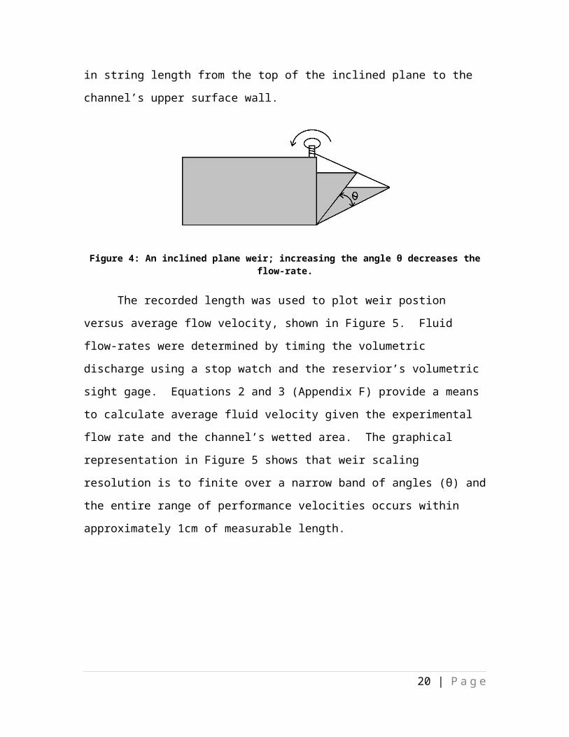
The recorded length was used to plot weir postion versus average flow velocity,
shown in Figure 5. Fluid flow-rates were determined by timing the volumetric discharge
using a stop watch and the reservior’s volumetric sight gage. Equations 2 and 3
(Appendix F) provide a means to calculate average fluid velocity given the experimental
flow rate and the channel’s wetted area. The graphical representation in Figure 5 shows
that weir scaling resolution is to finite over a narrow band of angles (θ) and the entire
range of performance velocities occurs within approximately 1cm of measurable length.
Figure 5: The entire range of performance velocities occurs over a narrow band of string lengths.
14 | P a g e
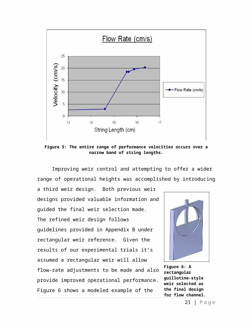
Improving weir control and attempting to offer a wider range of operational
heights was accomplished by introducing a third weir design. Both previous weir designs
provided valuable information and guided the final weir selection made. The refined
weir design follows guidelines provided in Appendix B under
rectangular weir reference. Given the results of our
experimental trials it’s assumed a rectangular weir will allow
flow-rate adjustments to be made and also provide improved
operational performance. Figure 6 shows a modeled example
of the final weir design selected and manufactured for our
flow channel.
Reservior System
Suppling and recirculating working fluid for the flow
channel required two main specifications to be considered.
First the supply reservoir needed to provide a continuous flow rate for at least 30 seconds
duration and the supply needed to be done without any pumps or electrical interference.
Using a 55 gallon supply tank with an elevation head of three feet was determined
appropriate to maintain continuous fluid flow at a maximum velocity of 20cm/s, or
approximately 0.70gal/s for a wetted area of 129cm2. Recognizing a change in elevation
head will occur as water leaves the supply reservoir a second supply reservoir was
suggested to the customer.
Despite our recommendation it was the customer’s decision to attempt a final
design without an additional head supply. The velocity potential lost due to variable head
supply was calculated using the three foot elevation datum and the maximum fluid
elevation represented by a full supply reservoir. The percentage difference between the
maximum (full supply tank) head and the minimum (3ft datum height) head was
calculated and a loss of 20% was iterated back to the customer. Since velocity potential
follows the square-root function, Equation 6 (√2 gh=V ) the relationship between
velocity and elevation is not linear and loss over the tank height is considered acceptable
by the customer. Consequently, the final design includes only one supply reservoir and a
slight potential energy loss is evidenced.
15 | P a g e
Figure 6: A rectangular guillotine-style weir selected as the final design for flow channel.
Designing the fluid recirculation system considered the specification that refilling
the supply reservoir needed to happen as quickly as possible. The main constraint here
was sizing a pump that could refill the supply reservoir within 1 minute and maintaining
a reasonable cost below $200. Calculating the frictional losses and the required head
needed are provided in Appendix G. Giving precedence to cost rather than performance
we settled on a pump selection that provided 70% the specified flow-rate of 50gpm and
had a total cost under $200. A pump performance curve for the final design selection is
represented in Appendix G.
Acknowledgements
The Fish Testing Flow Tank Team would like to thank our sponsor, Dr. Randy
Zelick, for trusting us with this project and providing us with such a learning opportunity.
We would also like to thank our Capstone Advisor, Dr. Lemmy Meekisho, for his support
and guidance through the course of the last two terms. Special thanks to Dr. VanWinkle
for the lab space he let us use, Dr. Cal for flow modification ideas, and Dr. Kohles for
facilitating this project with the PSU Biology Department.
16 | P a g e
Works Cited
Blake, Robert W. "Biomechanics of Rheotaxis in Six Teleost Genera." NRS Research
Press (2006). Print.
Braithwaite, V. A., and J. R. Girvan. "Use of Water Flow Direction to Provide Spatial
Information in a Small-scale Orientation Task." Journal of Fish Biology A
2003.63 (2003): 74-83. Print.
Budynas, Richard G., J. Keith. Nisbett, and Joseph Edward. Shigley. Shigley's
Mechanical Engineering Design. Boston: McGraw-Hill, 2008. Print.
"Engineering Tables - CMC Letco Ind." Letco Incorporated | Stainless Steel and Alloy
Fabricators | Pressure Vessels, Tanks, and Reactors. 2000. Web. 06 June 2010.
<http://www.cmc-letco.com/engineeringtables.php?value=5>.
Hofmann, Volker, Randy Zelick, and Horst Bleckmann. "Response of Midbrain Lateral
Line Units in Goldfish, Carassius Auratus, to Bulk Water Flow." Print.
"Moody Diagram." Http://www.engineeringtoolbox.com. Web. 6 June 2010.
Munson, Bruce Roy, Donald F. Young, and T. H. Okiishi. Fundamentals of Fluid
Mechanics. Hoboken, NJ: J. Wiley & Sons, 2006. Print.
"The Water Measurement Manual." Bureau of Reclamation Homepage. Web. 06 June
2010. <http://www.usbr.gov/pmts/hydraulics_lab/pubs/wmm/>.
17 | P a g e

Appendix A: Moody Diagram
Figure 7: Moody Diagram
18 | P a g e
Appendix B: Weir Design Proportions
Figure 8: Weir Proportion from the Bureau of Reclamation
19 | P a g e
Appendix C: Experimental DataTable 4: Raw Data for Comparison of Different Channel Geometries
Cross-sectional Geometry Description
Ac (cm^2)
P (cm) D (m) V (m/s) v (m^2/s) Re
Round r = 7.62 cm Fixed area 130 29.110.04465819
3 0.2 0.00000112 7970
0.04465819
3 0.175 0.00000112 6980
0.04465819
3 0.15 0.00000112 5980
0.04465819
3 0.125 0.00000112 4980
0.04465819
3 0.1 0.00000112 3990
0.04465819
3 0.075 0.00000112 2990
0.04465819
3 0.05 0.00000112 1990
0.04465819
3 0.025 0.00000112 1000
Square d = 11.4 cm Fixed area 130 34.20.03801169
6 0.2 0.00000112 6790
0.03801169
6 0.175 0.00000112 5940
0.03801169
6 0.15 0.00000112 5090
0.03801169
6 0.125 0.00000112 4240
0.03801169
6 0.1 0.00000112 3390
0.03801169
6 0.075 0.00000112 2550
0.03801169
6 0.05 0.00000112 1700
0.03801169
6 0.025 0.00000112 850
Triangulard = w = 16.12 cm Fixed area 130 36.1 0.03601108 0.2 0.00000112 6430
0.03601108 0.175 0.00000112 5630 0.03601108 0.15 0.00000112 4820 0.03601108 0.125 0.00000112 4020 0.03601108 0.1 0.00000112 3220 0.03601108 0.075 0.00000112 2410 0.03601108 0.05 0.00000112 1610 0.03601108 0.025 0.00000112 800
Where: Ac = Fluid Area
P = Wetted Perimeter
D = Hydraulic Diameter
20 | P a g e
V = Fluid Velocity
v = Dynamic viscosity
Re = Reynolds number
Table 5: Wooden Weir with Plastic Inserts Raw Data
Start Volume (gal)
Area (cm^2)
Weir Insert Size Q (gpm) Q (cm^3/s)
Velocity (cm/s)
25 129 medium 0.2231 844.56 6.55
35 129none (wood only) 0.6044 2288.01 17.74
30 129none (wood only) 0.6015 2277.33 17.65
30 129 small 0.3036 1149.4 8.91
Table 6: Inclined Weir String Length vs. Fluid Velocity
Flow Rate (cm/s)
Area (m^2)
gal
Seconds
gal/sec
m^3/sec
String Length (in)
Velocity (cm/s)
20.35690467 0.0129 30 43.24 0.6938 0.002626 6.4375 20.4
19.59119871 0.0129 30 44.93 0.6677 0.002527 6.25 19.6
18.50005377 0.0129 30 47.58 0.6305 0.002387 6.15625 18.5
18.51172572 0.0129 20 31.7 0.6309 0.002388 6.125 18.5
2.934108527 0.0129 30 300 0.1 0.000379 5.75 2.9
21 | P a g e
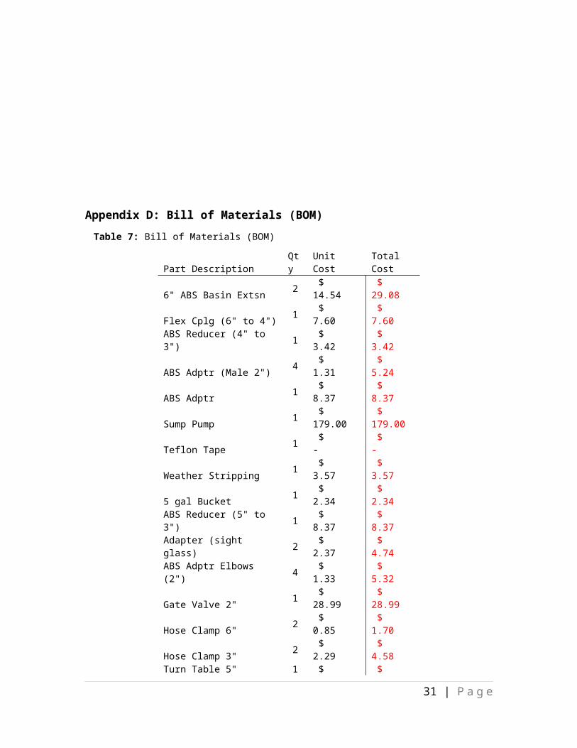
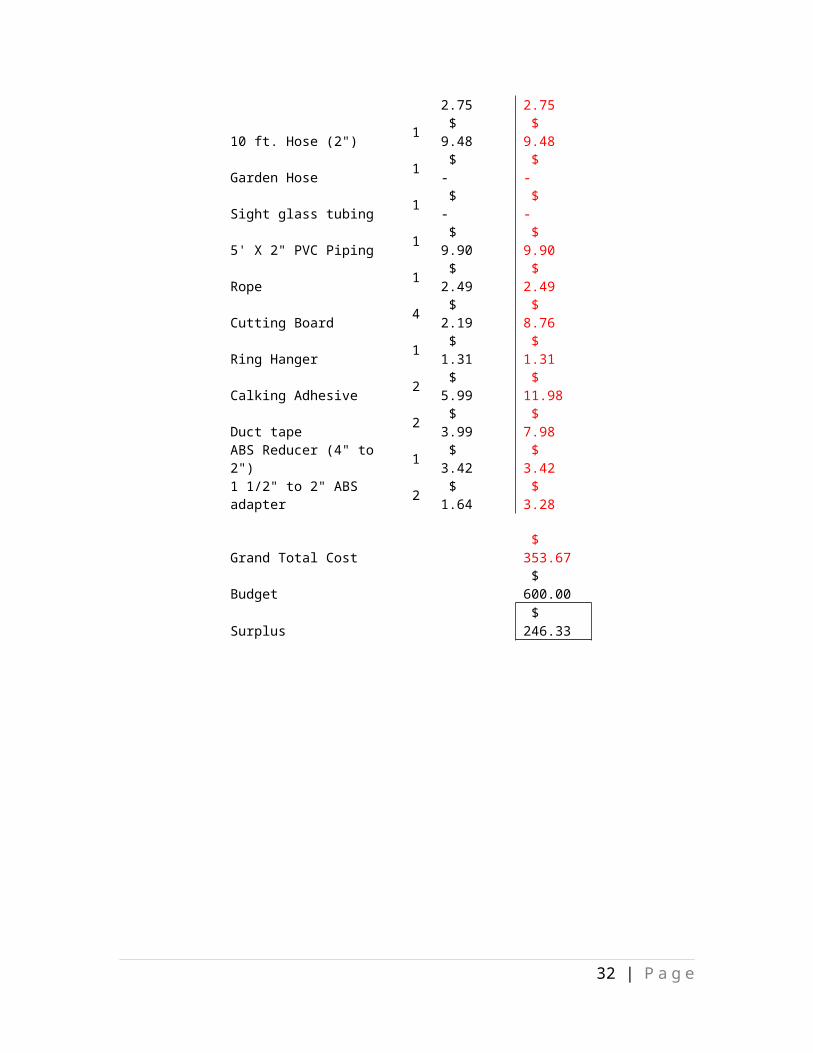
Appendix D: Bill of Materials (BOM)Table 7: Bill of Materials (BOM)
Part Description Qty Unit Cost Total Cost6" ABS Basin Extsn 2 $ 14.54 $ 29.08 Flex Cplg (6" to 4") 1 $ 7.60 $ 7.60 ABS Reducer (4" to 3") 1 $ 3.42 $ 3.42 ABS Adptr (Male 2") 4 $ 1.31 $ 5.24 ABS Adptr 1 $ 8.37 $ 8.37 Sump Pump 1 $ 179.00 $ 179.00 Teflon Tape 1 $ - $ - Weather Stripping 1 $ 3.57 $ 3.57 5 gal Bucket 1 $ 2.34 $ 2.34 ABS Reducer (5" to 3") 1 $ 8.37 $ 8.37 Adapter (sight glass) 2 $ 2.37 $ 4.74 ABS Adptr Elbows (2") 4 $ 1.33 $ 5.32 Gate Valve 2" 1 $ 28.99 $ 28.99 Hose Clamp 6" 2 $ 0.85 $ 1.70 Hose Clamp 3" 2 $ 2.29 $ 4.58 Turn Table 5" 1 $ 2.75 $ 2.75 10 ft. Hose (2") 1 $ 9.48 $ 9.48 Garden Hose 1 $ - $ - Sight glass tubing 1 $ - $ - 5' X 2" PVC Piping 1 $ 9.90 $ 9.90 Rope 1 $ 2.49 $ 2.49 Cutting Board 4 $ 2.19 $ 8.76 Ring Hanger 1 $ 1.31 $ 1.31 Calking Adhesive 2 $ 5.99 $ 11.98 Duct tape 2 $ 3.99 $ 7.98 ABS Reducer (4" to 2") 1 $ 3.42 $ 3.42 1 1/2" to 2" ABS adapter 2 $ 1.64 $ 3.28
Grand Total Cost $ 353.67 Budget $ 600.00
22 | P a g e
Surplus $ 246.33
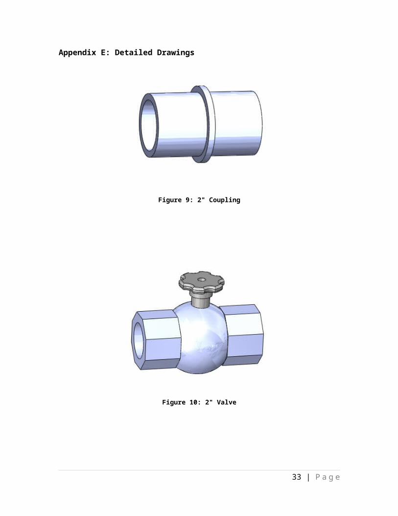
Appendix E: Detailed Drawings
Figure 9: 2" Coupling
23 | P a g e
Figure 10: 2" Valve
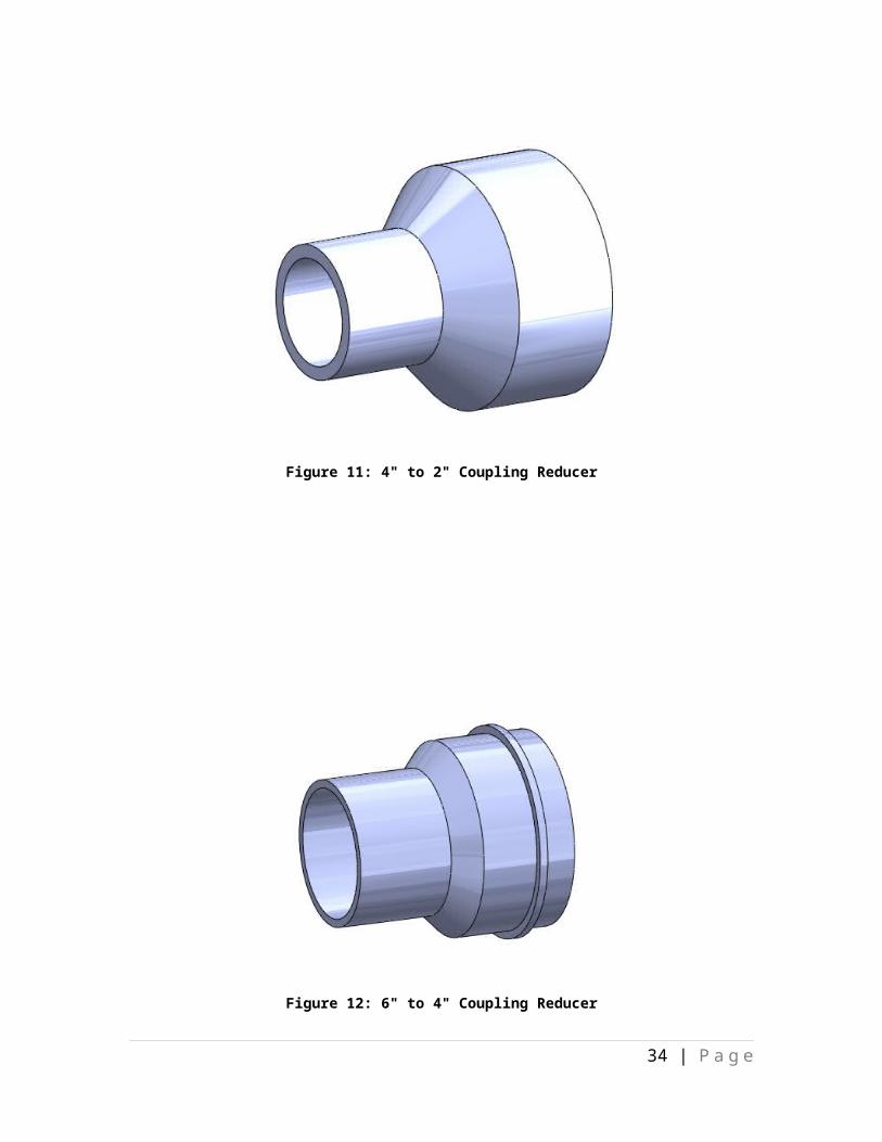
Figure 11: 4" to 2" Coupling Reducer
24 | P a g e

Figure 12: 6" to 4" Coupling Reducer
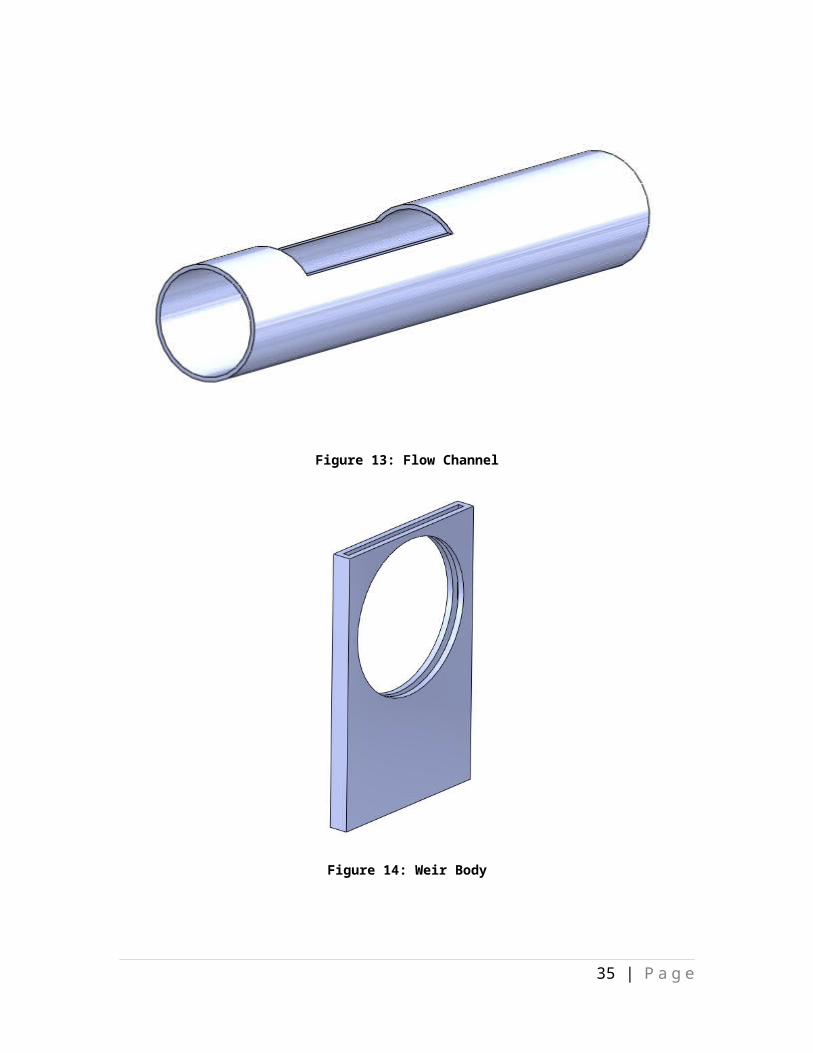
Figure 13: Flow Channel
25 | P a g e
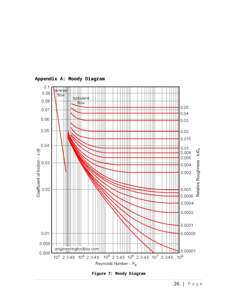
Figure 14: Weir Body
Figure 15: Adjustable Weir Gate
26 | P a g e
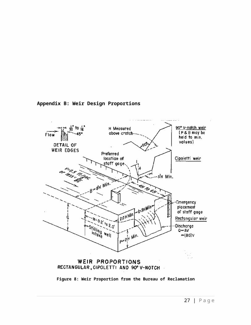
Figure 16: Turn Table Channel Cradle
Figure 17: Stress Analysis for Turn Table Cradle
27 | P a g e
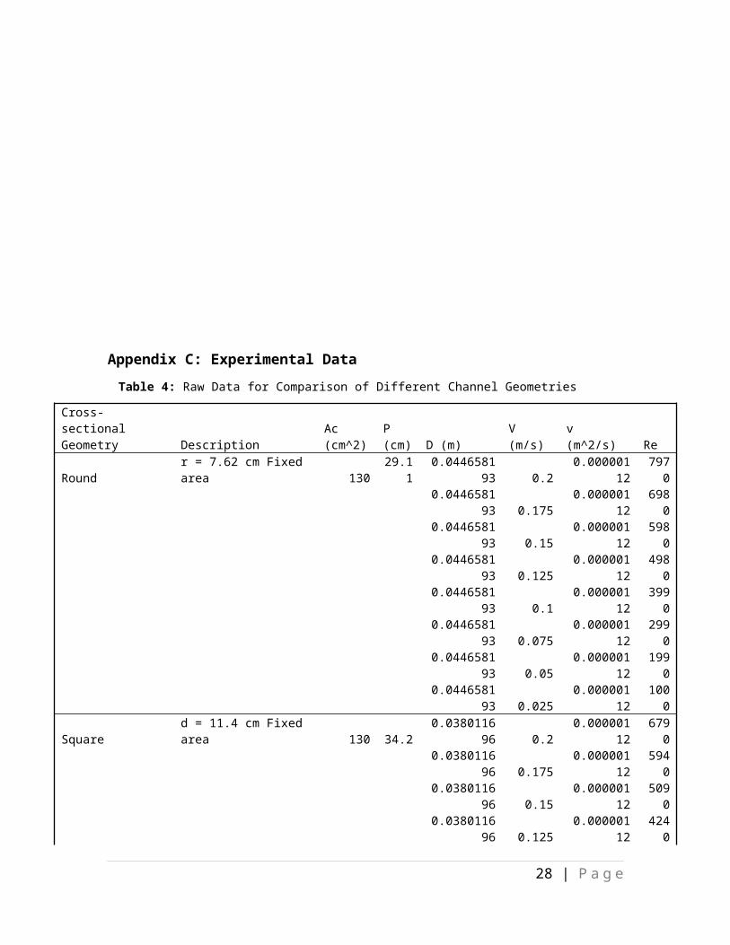
Figure 18: Turn Table Base
Figure 19: Stress Analysis for Turn Table Base
28 | P a g e
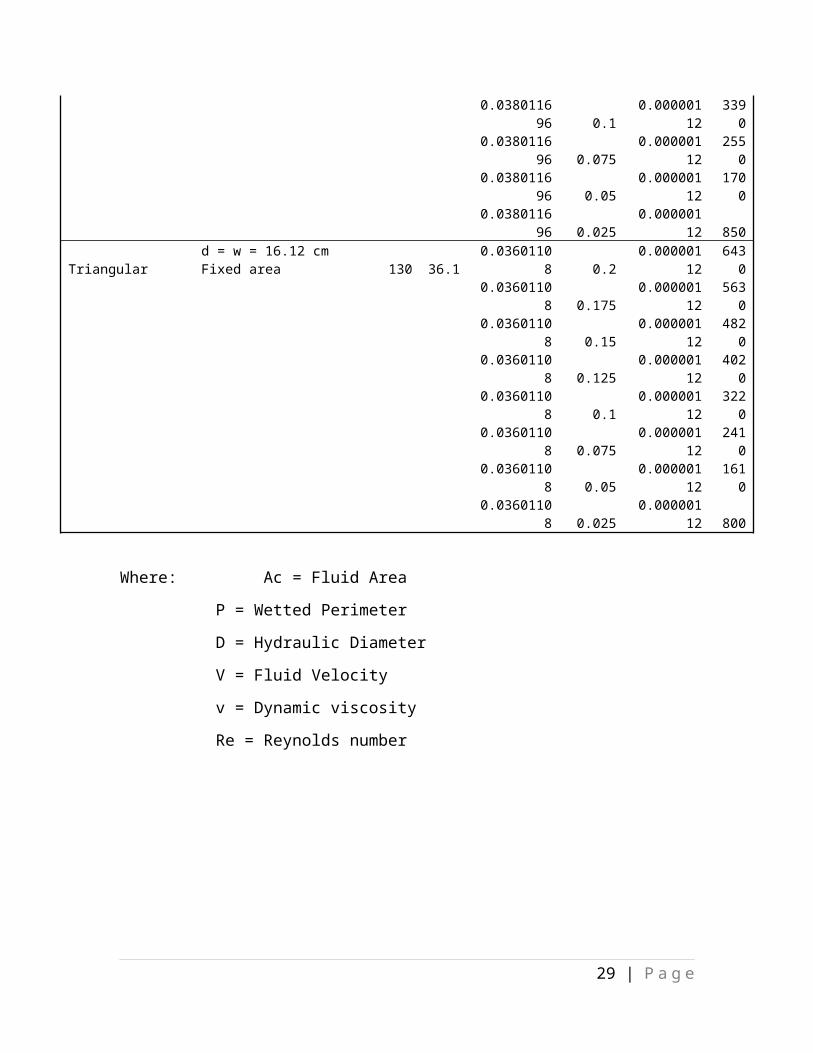
Figure 20: Turn Table
29 | P a g e
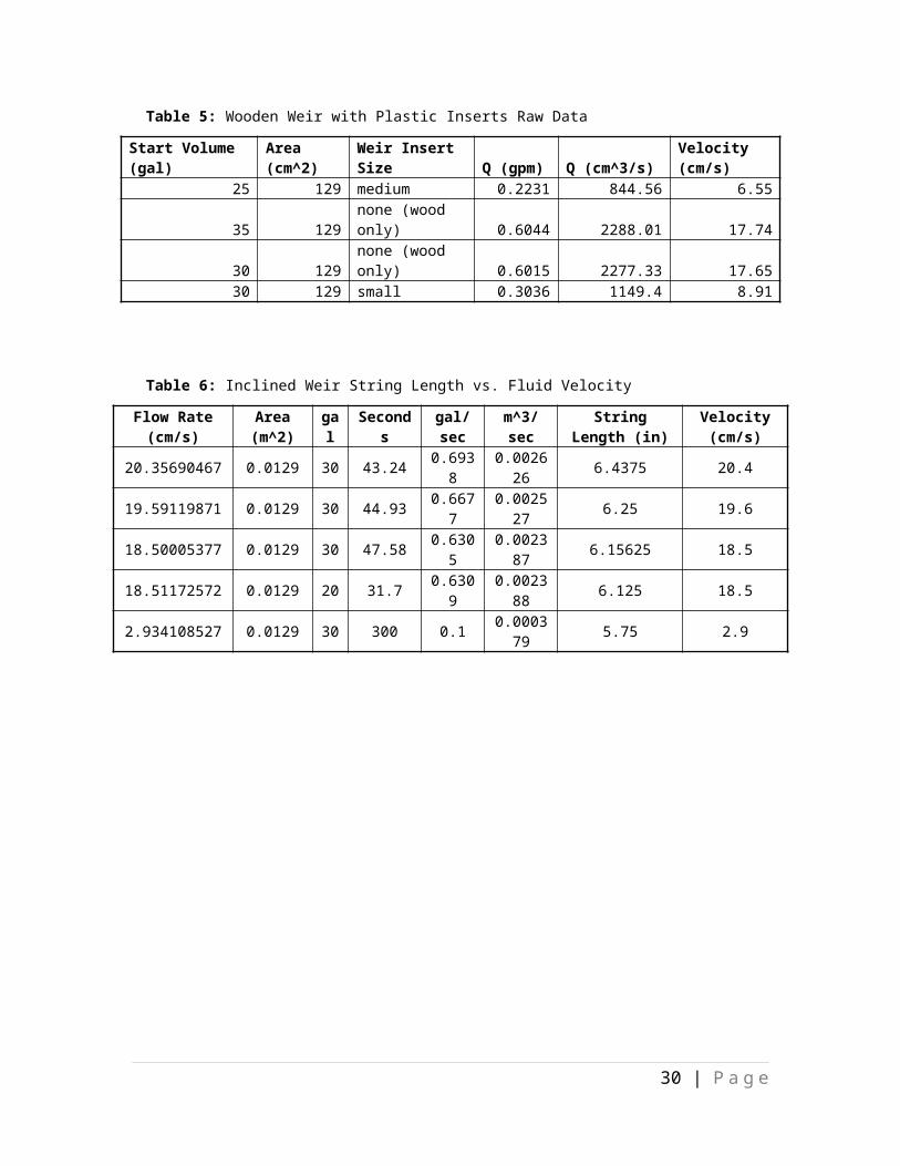
Figure 21: Reservoir Stand
Appendix F: Equations
30 | P a g e
Calculate Stress on member:
PA
=σ Equation 1
Conservation of Mass:
Q¿=Qout Equation 2
Where Q=A i∗V i Equation 3
Reynolds Number Calculation:
ℜ=Dh∗V
V H 2 O@ 270CEquation 4
Where Dh=Aw
PwEquation 5
Bernoulli’s:
√2gh=V Equation 6
31 | P a g e
Appendix G: Pump Selection
Figure 22: Pump curve for selected pump design
Head LossOperating Pt.→ Q=50gpmTank Head → 8ft 1½ inch Schedule 80 Plastic Pipe (22.8-ft)- 16 ft. head loss / 100 ft. of pipe = Six 90° Fittings @ Vavg = 2.25-ft/s- 4 ft equivalent pipe length / fittingNeglect Pump LossTotal Loss = (4 ft. * 6 fittings + 22.8 ft.)*(16 ft. head loss/100 ft. of pipe) + 8 ft.
= 15.5 ft. head loss
32 | P a g e
Selected Pump Ideal Pump
33.3 GPM 50 GPMMinutes to Fill Reservoir
1.5 1
Appendix H: PDS Adherence
Table 8: PDS Adherence
Specification Priority Metric Target Satisfaction of
CompletionFrequency Interference *** yes/no no ***Fluid Flow Profile *** yes/no yes ***Minimum Flow Velocity * cm/s 0 ***Maximum Flow Velocity (min) *** cm/s 10 ***Test Duration ** s 60 ***Resistant To Oxidation * yes/no yes ***Cost To Produce ** $ 600 ***Fish Holding Tank Depth (static flow) *** cm ~7.5 ***
Rotation of Tank * Angle (positive or negative degrees) +/-15 *
Off-The-Shelf Parts * yes/no yes ***
Ease of Repair * People Required to Fix 1 ***
Durable * yes/no yes **Fits on Existing Air Table ** yes/no yes **Spatial Interference with Testing Equipment ** yes/no no **
Allows Visual Observation of Fish *** yes/no yes ***
Fluid Containment ** yes/no yes **User Ergonomic Safety *** yes/no yes **Specimen Safety ** yes/no yes ***Structure Bio-Compatible ** yes/no yes ***Visually Aesthetic * yes/no yes *
33 | P a g e
Appendix I: Flow Analysis
Figure 23: An example of the simulated flow model used in SolidWorks. This form of simulation was shown to be quite inaccurate and therefore was omitted from final calculations.
34 | P a g e
Appendix J: Assembly Drawings
Figure 24: Collapsed (upper) and Exploded (lower) Views of Final Flow Channel
35 | P a g e

Figure 25: Collapsed (upper) and Exploded (lower) views of Turn Table
36 | P a g e