Embed Size (px)
Citation preview
THE 19TH INTERNATIONAL CONFERENCE ON COMPOSITE MATERIALS
1 Introduction
The use of composite materials for gas transportation has recently known a growing interest. The material under study is a Polyamide 6 (PA6) matrix reinforced with unidirectional continuous Glass Fibres (GF) referred to as PA6GF. This material is produced thanks to a pultrusion process that allows high fibre volume fraction which enhanced structure stiffness. This process also introduces void defects in the composite material. These manufacturing defects are non avoidable without high temperature and high pressure conditions which drastically increase costs. The present contribution is devoted to highlight influence microstructural variabilities such as void defects and local fibre volume fraction in the composite material and to take them into account in finite element models in order to fully control composite behaviors.
2 Experimental Investigations
2.1 Microstructural variabilities
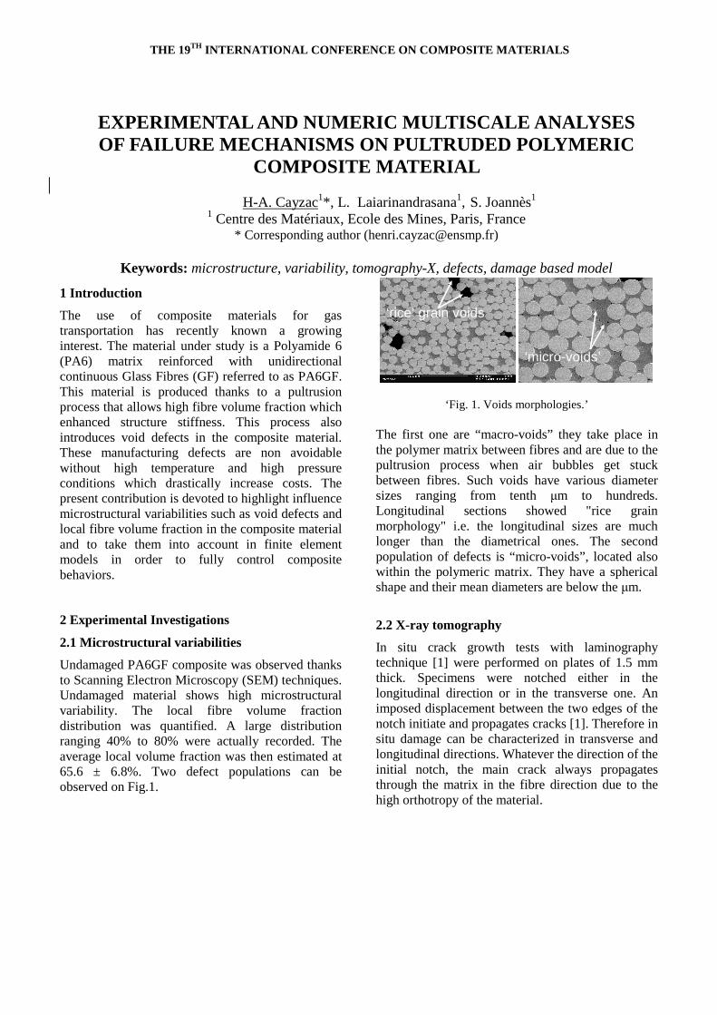
Undamaged PA6GF composite was observed thanks to Scanning Electron Microscopy (SEM) techniques. Undamaged material shows high microstructural variability. The local fibre volume fraction distribution was quantified. A large distribution ranging 40% to 80% were actually recorded. The average local volume fraction was then estimated at 65.6 ± 6.8%. Two defect populations can be observed on Fig.1.
‘rice’ grain voids
‘micro-voids’
‘rice’ grain voids
‘micro-voids’
‘Fig. 1. Voids morphologies.’ The first one are “macro-voids” they take place in the polymer matrix between fibres and are due to the pultrusion process when air bubbles get stuck between fibres. Such voids have various diameter sizes ranging from tenth µm to hundreds. Longitudinal sections showed "rice grain morphology" i.e. the longitudinal sizes are much longer than the diametrical ones. The second population of defects is “micro-voids”, located also within the polymeric matrix. They have a spherical shape and their mean diameters are below the µm.
2.2 X-ray tomography
In situ crack growth tests with laminography technique [1] were performed on plates of 1.5 mm thick. Specimens were notched either in the longitudinal direction or in the transverse one. An imposed displacement between the two edges of the notch initiate and propagates cracks [1]. Therefore in situ damage can be characterized in transverse and longitudinal directions. Whatever the direction of the initial notch, the main crack always propagates through the matrix in the fibre direction due to the high orthotropy of the material.
EXPERIMENTAL AND NUMERIC MULTISCALE ANALYSES OF FAILURE MECHANISMS ON PULTRUDED POLYMERIC
COMPOSITE MATERIAL
H-A. Cayzac1*, L. Laiarinandrasana1, S. Joannès1
1 Centre des Matériaux, Ecole des Mines, Paris, France * Corresponding author ([email protected])
Keywords: microstructure, variability, tomography-X, defects, damage based model
THE 19TH INTERNATIONAL CONFERENCE ON COMPOSITE MATERIALS
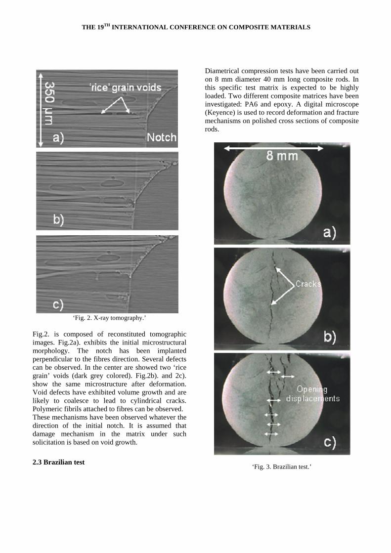
‘Fig. 2. X-ray tomography.’
Fig.2. is composed of reconstituted tomographic images. Fig.2a). exhibits the initial microstructural morphology. The notch has been implanted perpendicular to the fibres direction. Several defects can be observed. In the center are showed two ‘rice grain’ voids (dark grey colored). Fig.2b). and 2c). show the same microstructure after deformation. Void defects have exhibited volume growth and are likely to coalesce to lead to cylindrical cracks. Polymeric fibrils attached to fibres can be observed. These mechanisms have been observed whatever the direction of the initial notch. It is assumed that damage mechanism in the matrix under such solicitation is based on void growth.
2.3 Brazilian test
Diametrical compression tests have been carried out on 8 mm diameter 40 mm long composite rods. In this specific test matrix is expected to be highly loaded. Two different composite matrices have been investigated: PA6 and epoxy. A digital microscope (Keyence) is used to record deformation and fracture mechanisms on polished cross sections of composite rods.
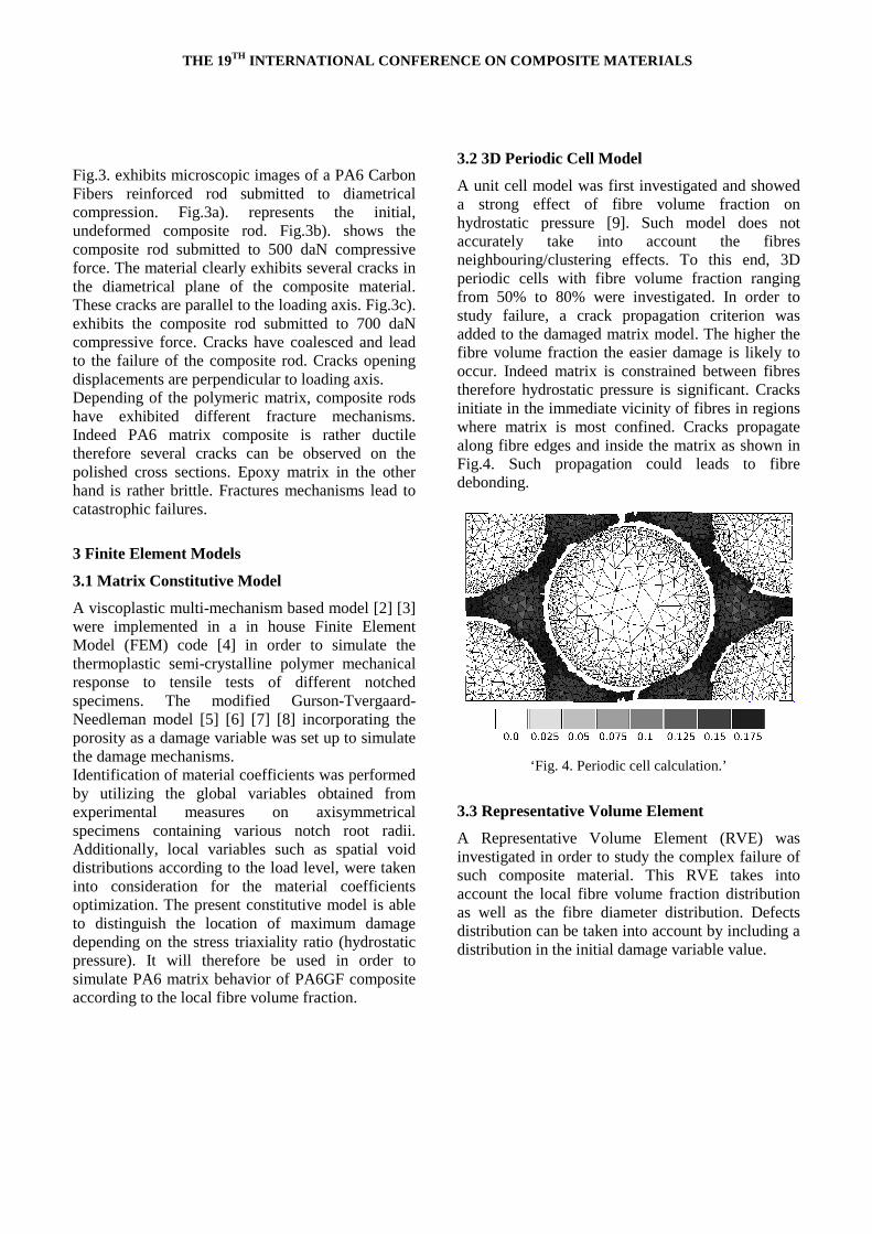
‘Fig. 3. Brazilian test.’
THE 19TH INTERNATIONAL CONFERENCE ON COMPOSITE MATERIALS
Fig.3. exhibits microscopic images of a PA6 Carbon Fibers reinforced rod submitted to diametrical compression. Fig.3a). represents the initial, undeformed composite rod. Fig.3b). shows the composite rod submitted to 500 daN compressive force. The material clearly exhibits several cracks in the diametrical plane of the composite material. These cracks are parallel to the loading axis. Fig.3c). exhibits the composite rod submitted to 700 daN compressive force. Cracks have coalesced and lead to the failure of the composite rod. Cracks opening displacements are perpendicular to loading axis. Depending of the polymeric matrix, composite rods have exhibited different fracture mechanisms. Indeed PA6 matrix composite is rather ductile therefore several cracks can be observed on the polished cross sections. Epoxy matrix in the other hand is rather brittle. Fractures mechanisms lead to catastrophic failures.
3 Finite Element Models
3.1 Matrix Constitutive Model
A viscoplastic multi-mechanism based model [2] [3] were implemented in a in house Finite Element Model (FEM) code [4] in order to simulate the thermoplastic semi-crystalline polymer mechanical response to tensile tests of different notched specimens. The modified Gurson-Tvergaard-Needleman model [5] [6] [7] [8] incorporating the porosity as a damage variable was set up to simulate the damage mechanisms. Identification of material coefficients was performed by utilizing the global variables obtained from experimental measures on axisymmetrical specimens containing various notch root radii. Additionally, local variables such as spatial void distributions according to the load level, were taken into consideration for the material coefficients optimization. The present constitutive model is able to distinguish the location of maximum damage depending on the stress triaxiality ratio (hydrostatic pressure). It will therefore be used in order to simulate PA6 matrix behavior of PA6GF composite according to the local fibre volume fraction.
3.2 3D Periodic Cell Model
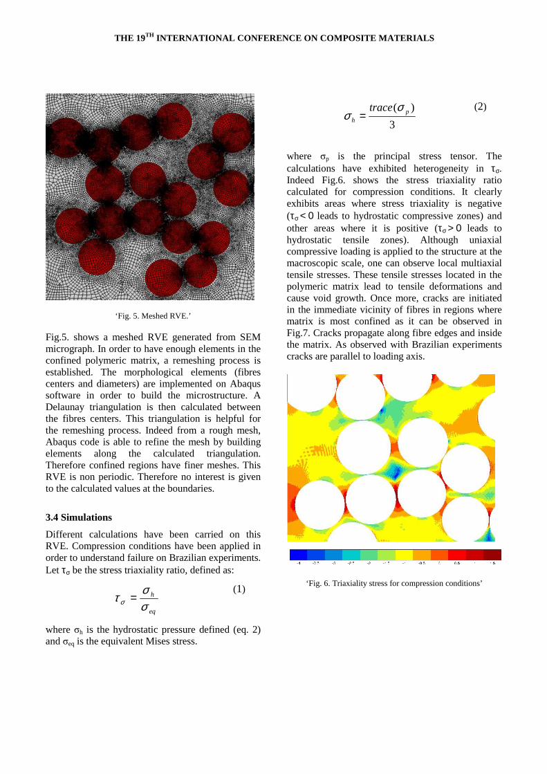
A unit cell model was first investigated and showed a strong effect of fibre volume fraction on hydrostatic pressure [9]. Such model does not accurately take into account the fibres neighbouring/clustering effects. To this end, 3D periodic cells with fibre volume fraction ranging from 50% to 80% were investigated. In order to study failure, a crack propagation criterion was added to the damaged matrix model. The higher the fibre volume fraction the easier damage is likely to occur. Indeed matrix is constrained between fibres therefore hydrostatic pressure is significant. Cracks initiate in the immediate vicinity of fibres in regions where matrix is most confined. Cracks propagate along fibre edges and inside the matrix as shown in Fig.4. Such propagation could leads to fibre debonding.
‘Fig. 4. Periodic cell calculation.’
3.3 Representative Volume Element
A Representative Volume Element (RVE) was investigated in order to study the complex failure of such composite material. This RVE takes into account the local fibre volume fraction distribution as well as the fibre diameter distribution. Defects distribution can be taken into account by including a distribution in the initial damage variable value.
THE 19TH INTERNATIONAL CONFERENCE ON COMPOSITE MATERIALS
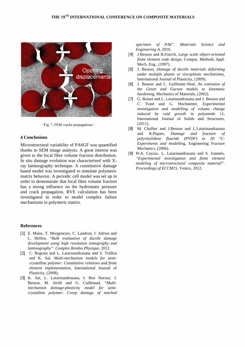
‘Fig. 5. Meshed RVE.’ Fig.5. shows a meshed RVE generated from SEM micrograph. In order to have enough elements in the confined polymeric matrix, a remeshing process is established. The morphological elements (fibres centers and diameters) are implemented on Abaqus software in order to build the microstructure. A Delaunay triangulation is then calculated between the fibres centers. This triangulation is helpful for the remeshing process. Indeed from a rough mesh, Abaqus code is able to refine the mesh by building elements along the calculated triangulation. Therefore confined regions have finer meshes. This RVE is non periodic. Therefore no interest is given to the calculated values at the boundaries.
3.4 Simulations
Different calculations have been carried on this RVE. Compression conditions have been applied in order to understand failure on Brazilian experiments. Let τσ be the stress triaxiality ratio, defined as:
eq
h
σστ σ =
(1)
where σh is the hydrostatic pressure defined (eq. 2) and σeq is the equivalent Mises stress.
3
)( ph
trace σσ =
(2)
where σp is the principal stress tensor. The calculations have exhibited heterogeneity in τσ. Indeed Fig.6. shows the stress triaxiality ratio calculated for compression conditions. It clearly exhibits areas where stress triaxiality is negative (τσ < 0 leads to hydrostatic compressive zones) and other areas where it is positive (τσ > 0 leads to hydrostatic tensile zones). Although uniaxial compressive loading is applied to the structure at the macroscopic scale, one can observe local multiaxial tensile stresses. These tensile stresses located in the polymeric matrix lead to tensile deformations and cause void growth. Once more, cracks are initiated in the immediate vicinity of fibres in regions where matrix is most confined as it can be observed in Fig.7. Cracks propagate along fibre edges and inside the matrix. As observed with Brazilian experiments cracks are parallel to loading axis.
‘Fig. 6. Triaxiality stress for compression conditions’
THE 19TH INTERNATIONAL CONFERENCE ON COMPOSITE MATERIALS
‘Fig. 7. FEM cracks propagations.’
4 Conclusions
Microstructural variability of PA6GF was quantified thanks to SEM image analysis. A great interest was given to the local fibre volume fraction distribution. In situ damage evolution was characterised with X-ray laminography technique. A constitutive damage based model was investigated to simulate polymeric matrix behavior. A periodic cell model was set up in order to demonstrate that local fibre volume fraction has a strong influence on the hydrostatic pressure and crack propagation. RVE calculation has been investigated in order to model complex failure mechanisms in polymeric matrix.
References
[1] E. Maire, T. Morgeneyer, C. Landron, J. Adrien and L. Helfen, “Bulk evaluation of ductile damage development using high resolution tomography and laminography”. Comptes Rendus Physique, 2012.
[2] C. Regrain and L. Laiarinandrasana and S. Toillon and K. Saï, Multi-mechanism models for semi-crystalline polymer: Constitutive relations and finite element implementation, International Journal of Plasticity, (2008).
[3] K. Saï, L. Laiarinandrasana, I. Ben Naceur, J. Besson, M. Jeridi and G. Cailletaud, “Multi-mechanism damage-plasticity model for semi-crystalline polymer: Creep damage of notched
specimen of PA6”. Materials Science and Engineering A, 2010.
[4] J.Besson and R.Foerch, Large scale object-oriented finite element code design, Comput. Methods Appl. Mech. Eng., (1997).
[5] J. Besson, Damage of ductile materials deforming under multiple plastic or viscoplastic mechanisms, International Journal of Plasticity, (2009).
[6] J. Besson and C. Guillemer-Neel, An extension of the Green and Gurson models to kinematic hardening, Mechanics of Materials, (2002).
[7] G. Boisot and L. Laiarinandrasana and J. Besson and C. Fond and G. Hochstetter, Experimental investigation and modelling of volume change induced by void growth in polyamide 11, International Journal of Solids and Structures, (2011).
[8] M. Challier and J.Besson and L.Laiarinandrasana and R.Piques, Damage and fracture of polyvinylidene fluoride (PVDF) at 20 °C: Experiments and modelling, Engineering Fracture Mechanics, (2006).
[9] H-A. Cayzac, L. Laiarinandrasana and S. Joannès, “Experimental investigation and finite element modeling of microstructural composite material”. Proceedings of ECCM15, Venice, 2012.


![Improvement of Interfacial Shear Strength Using ...confsys.encs.concordia.ca/ICCM19/AllPapers/FinalVersion/RUT80577.pdf · modified by introducing nano, ... the IFSS [15] and, based](https://img.pdfslide.net/doc/110x75/5abd66f07f8b9a8e3f8bba70/improvement-of-interfacial-shear-strength-using-by-introducing-nano-the.jpg)