Embed Size (px)
Citation preview
Engineering and Technology
2017; 4(5): 56-64
http://www.aascit.org/journal/et
ISSN: 2381-1072 (Print); ISSN: 2381-1080 (Online)
Keywords CFRP Composites,
External Confinement,
FRP Volumetric Ratio,
RC Column
Received: April 18, 2017
Accepted: September 6, 2017
Published: October 13, 2017
Experimental Investigation of Concrete Externally Confined by CFRP Composites
Habib-Abdelhak Mesbah1, Riad Benzaid
2, *
1Laboratory of Civil Engineering and Mechanical Engineering, National Institute of Applied
Sciences of Rennes, University of Rennes 1, France 2Laboratory of Geological Engineering, University of Mohammed Seddik Benyahia, Jijel, Algeria
Email address [email protected] (R. Benzaid) *Corresponding author
Citation Habib-Abdelhak Mesbah, Riad Benzaid. Experimental Investigation of Concrete Externally
Confined by CFRP Composites. Engineering and Technology. Vol. 4, No. 5, 2017, pp. 56-64.
Abstract The present study deals with the analysis of experimental results, in terms of load carrying
capacity and strains, obtained from tests on reinforced concrete (RC) columns,
strengthened with external carbon fiber reinforced polymer (CFRP) sheets. In this work,
we are interested in the effect of the volumetric ratio of the fiber-reinforced polymer (ρFRP)
on the effectiveness of the CFRP external confinement. A total of 36 specimens were
subjected to axial compression. All test specimens were loaded to failure in axial
compression. Compressive stress, axial and hoop strains have been recorded to evaluate the
stress-strain relationship, ultimate strength and ductility of the specimens. Results clearly
demonstrate that for a given confinement level, the increase in cross-sectional dimensions
of the columns would result in a decrease in the volumetric ratio of the fiber-reinforced
polymer (ρFRP), which will result in a decrease in the strength of the externally-confined-
concrete columns. On the other hand, composite wrapping can enhance the structural
performance of RC columns in terms of both maximum strength and ductility.
1. Introduction
The use of fiber reinforced polymer (FRP) confined concrete columns has been proven
in enhancing the strength and the ductility of columns. Over the last two decades, a large
number of experimental and analytical studies have been conducted to understand and
simulate the compressive behavior of FRP confined concrete [1-6]. Such strengthening
technique has proved to be very effective in enhancing their ductility and axial load
capacity. Most of the available experimental data regarding FRP-confined columns have
been generated from tests on small-scale concrete specimens with normal strength [7-14].
So, the validation of these results and their applicability to large-scale RC columns is of
great practical interest. Published work in this field is relatively few [15-17]. More research
investigation is needed on this subject to study the effect of column’s diameter on the
effectiveness of the CFRP external confinement. The present paper deals with the analysis
of experimental results, in terms of load carrying capacity and strains, obtained from tests
on circular reinforced concrete columns, confined with external CFRP composite. The
principal study parameter was the volumetric ratio of the fiber-reinforced polymer (ρFRP).
2. FRP-Confined Concrete in Circular Columns
The confinement action exerted by the FRP on the concrete core is of the passive type,
57 Habib-Abdelhak Mesbah and Riad Benzaid: Experimental Investigation of Concrete
Externally Confined by CFRP Composites
that is, it arises as a result of the lateral expansion of concrete
under axial load.
As the axial stress increases, the corresponding lateral
strain increases and the confining device develops a tensile
hoop stress balanced by a uniform radial pressure which
reacts against the concrete lateral expansion [12, 18]. When
an FRP confined column is subject to axial compression, the
concrete expands laterally and this expansion is restrained by
the FRP. The confining action of the FRP composite for
circular concrete columns is shown in Figure 1. For circular
columns, the concrete is subject to uniform confinement, and
the maximum confining pressure provided by FRP composite
is related to the amount and strength of FRP and the diameter
of the confined concrete core. The maximum value of the
confinement pressure that the FRP can exert is attained when
the circumferential strain in the FRP reaches its ultimate
strain and the fibers rupture leading to brittle failure of the
column. This confining pressure is given by:
2
22 frpfrpfrpfrpfufrpfrp
l
f
d
ft
d
Etf
ρε=== (1)
Where fl is the lateral confining pressure, Efrp is the elastic
modulus of the FRP composite, εfu is the ultimate FRP tensile
strain, ffrp is the ultimate tensile strength of the FRP
composite, tfrp is the total thickness of the FRP, d is the
diameter of the concrete column, and ρfrp is the FRP
volumetric ratio given by the following equation for fully
wrapped circular cross section:
d
t
d
td frpfrp
frp
4
4/2==
ππ
ρ (2)
Figure 1. Confinement action of FRP jacket in circular sections.
3. Experimental Program
3.1. Materials Properties
Concrete mixtures: Three concrete mixtures were used to
achieve the desired range of unconfined concrete strength (26,
50 and 62 MPa), as shown in Table 1. Mixtures were
prepared in the laboratory using a mechanical mixer and
were used to cast the concrete specimens which were
wrapped with CFRP sheets after drying.
Table 1. Concrete mixture proportions.
Mixture no. I II III
Compressive cylinder strength, f’co (MPa) 25.93 49.46 61.81
Cement (kg/m3) 280a 400b 450c
Water (kg/m3) 180 183.86 170
Crushed gravel (kg/m3)
Ø 4/6 122.90 115.70 115.60
Ø 6/12 258.20 243.00 242.80
Ø 12/20 769.50 724.20 723.50
Sand Ø 0/4 (kg/m3) 729.10 686.30 685.60
Sika Viscocrete-Tempo12 (l/ m3), d - 0.85 1.55
Air content (%) 2.3 2.5 2.7
W/C 0.64 0.46 0.37
aPortland cement: CPA CEM II R 32.5 MPa, bPortland cement: CPA CEM I
R 42.5 MPa, cPortland cement: CPA CEM I R 52.5 MPa, dSika Viscocrete-
Tempo 12: High-range water reducing and super-plasticizing admixture.
CFRP composites: The carbon-fiber fabric used in this
study were the SikaWrap-230C/45 product, a unidirectional
wrap. The resin system that was used to bond the carbon
fabrics over the specimens in this work was the epoxy resin
made of two-parts, resin and hardener. The mixing ratio of
the two components by weight was 4:1. SikaWrap-230C/45
was field laminated using Sikadur-330 epoxy to form a
carbon fiber reinforced polymer wrap (CFRP) used to
strengthen the concrete specimens.
3.2. Fabrication of Test Specimens
The experimental program was carried out on circular
columns of 1000 mm height with two different diameters of
160 mm and 200 mm. For all RC specimens the longitudinal
steel ratio was constant for all specimens and equal to 2.25%.
Transverse ties (Ø 8 mm) were spaced every 140 mm. Series
definition and details are given in Table 2.
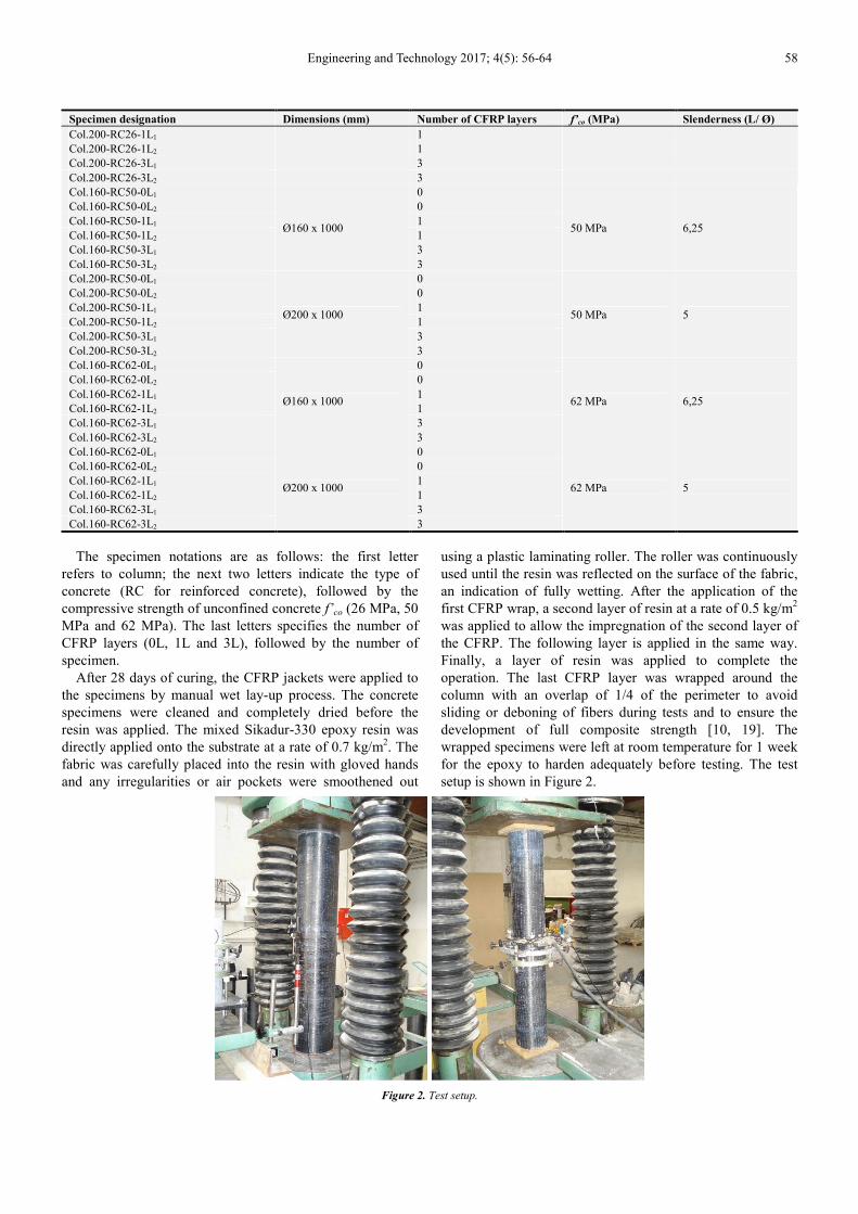
Table 2. Details of test specimens.
Specimen designation Dimensions (mm) Number of CFRP layers f’co (MPa) Slenderness (L/ Ø)
Col.160-RC26-0L1
Ø160 x 1000
0
26 MPa 6,25
Col.160-RC26-0L2 0
Col.160-RC26-1L1 1
Col.160-RC26-1L2 1
Col.160-RC26-3L1 3
Col.160-RC26-3L2 3
Col.200-RC26-0L1 Ø200 x 1000
0 26 MPa 5
Col.200-RC26-0L2 0
Engineering and Technology 2017; 4(5): 56-64 58
Specimen designation Dimensions (mm) Number of CFRP layers f’co (MPa) Slenderness (L/ Ø)
Col.200-RC26-1L1 1
Col.200-RC26-1L2 1
Col.200-RC26-3L1 3
Col.200-RC26-3L2 3
Col.160-RC50-0L1
Ø160 x 1000
0
50 MPa 6,25
Col.160-RC50-0L2 0
Col.160-RC50-1L1 1
Col.160-RC50-1L2 1
Col.160-RC50-3L1 3
Col.160-RC50-3L2 3
Col.200-RC50-0L1
Ø200 x 1000
0
50 MPa 5
Col.200-RC50-0L2 0
Col.200-RC50-1L1 1
Col.200-RC50-1L2 1
Col.200-RC50-3L1 3
Col.200-RC50-3L2 3
Col.160-RC62-0L1
Ø160 x 1000
0
62 MPa 6,25
Col.160-RC62-0L2 0
Col.160-RC62-1L1 1
Col.160-RC62-1L2 1
Col.160-RC62-3L1 3
Col.160-RC62-3L2 3
Col.160-RC62-0L1
Ø200 x 1000
0
62 MPa 5
Col.160-RC62-0L2 0
Col.160-RC62-1L1 1
Col.160-RC62-1L2 1
Col.160-RC62-3L1 3
Col.160-RC62-3L2 3
The specimen notations are as follows: the first letter
refers to column; the next two letters indicate the type of
concrete (RC for reinforced concrete), followed by the
compressive strength of unconfined concrete f’co (26 MPa, 50
MPa and 62 MPa). The last letters specifies the number of
CFRP layers (0L, 1L and 3L), followed by the number of
specimen.
After 28 days of curing, the CFRP jackets were applied to
the specimens by manual wet lay-up process. The concrete
specimens were cleaned and completely dried before the
resin was applied. The mixed Sikadur-330 epoxy resin was
directly applied onto the substrate at a rate of 0.7 kg/m2. The
fabric was carefully placed into the resin with gloved hands
and any irregularities or air pockets were smoothened out
using a plastic laminating roller. The roller was continuously
used until the resin was reflected on the surface of the fabric,
an indication of fully wetting. After the application of the
first CFRP wrap, a second layer of resin at a rate of 0.5 kg/m2
was applied to allow the impregnation of the second layer of
the CFRP. The following layer is applied in the same way.
Finally, a layer of resin was applied to complete the
operation. The last CFRP layer was wrapped around the
column with an overlap of 1/4 of the perimeter to avoid
sliding or deboning of fibers during tests and to ensure the
development of full composite strength [10, 19]. The
wrapped specimens were left at room temperature for 1 week
for the epoxy to harden adequately before testing. The test
setup is shown in Figure 2.
Figure 2. Test setup.
59 Habib-Abdelhak Mesbah and Riad Benzaid: Experimental Investigation of Concrete
Externally Confined by CFRP Composites
4. Test Results and Discussion
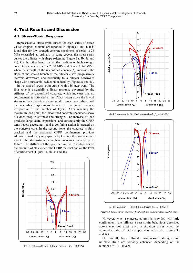
4.1. Stress-Strain Response
Representative stress-strain curves for each series of tested
CFRP-wrapped columns are reported in Figures 3 and 4. It is
found that for low strength concrete specimens of series 1: 26
MPa (classified as ordinary in some codes), the stress-strain
curves are bilinear with shape softening (Figure 3a, 3b, 4a and
4b). On the other hand, for similar medium or high strength
concrete specimens (Series 2: 50 MPa and Series 3: 62 MPa),
when the strength of the unconfined concrete f'co increases, the
slope of the second branch of the bilinear curve progressively
recovers downward and eventually to a bilinear downward
shape with a substantial reduction in ductility (Figure 3c and 4c).
In the case of stress-strain curves with a bilinear trend. The
first zone is essentially a linear response governed by the
stiffness of the unconfined concrete, which indicates that no
confinement is activated in the CFRP wraps since the lateral
strains in the concrete are very small. Hence the confined and
the unconfined specimens behave in the same manner,
irrespective of the number of layers. After reaching the
maximum load point, the unconfined concrete specimens show
a sudden drop in stiffness and strength. The increase of load
produces large lateral expansions, and consequently the CFRP
wrap reacts accordingly and a confining action is created on
the concrete core. In the second zone, the concrete is fully
cracked and the activated CFRP confinement provides
additional load carrying capacity by keeping the concrete core
intact. The stress-strain curve here increases linearly up to
failure. The stiffness of the specimen in this zone depends on
the modulus of elasticity of the CFRP material and on the level
of confinement (Figure 3a, 3b, 4a and 4b).
(a) RC columns Ø160x1000 mm (series-1: f’co = 26 MPa)
(b) RC columns Ø160x1000 mm (series-2: f’co = 50 MPa)
(c) RC columns Ø160x1000 mm (series-3: f’co = 62 MPa)
Figure 3. Stress-strain curves of FRP confined columns (Ø160x1000 mm).
However, when a concrete column is provided with little
confinement, the bilinear stress-strain behaviour described
above may not exist. Such a situation arises when the
volumetric ratio of FRP composite is very small (Figure 3c
and 4c).
On overall, both ultimate compressive strength and
ultimate strain are variably enhanced depending on the
number of CFRP layers.
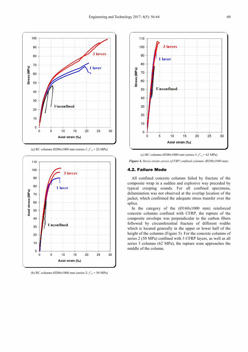
Engineering and Technology 2017; 4(5): 56-64 60
(a) RC columns Ø200x1000 mm (series-1: f’co = 26 MPa)
(b) RC columns Ø200x1000 mm (series-2: f’co = 50 MPa)
(c) RC columns Ø200x1000 mm (series-3: f’co = 62 MPa)
Figure 4. Stress-strain curves of FRP confined columns (Ø200x1000 mm).
4.2. Failure Mode
All confined concrete columns failed by fracture of the
composite wrap in a sudden and explosive way preceded by
typical creeping sounds. For all confined specimens,
delamination was not observed at the overlap location of the
jacket, which confirmed the adequate stress transfer over the
splice.
In the category of the (Ø160x1000 mm) reinforced
concrete columns confined with CFRP, the rupture of the
composite envelope was perpendicular to the carbon fibers
followed by circumferential fracture of different widths
which is located generally in the upper or lower half of the
height of the columns (Figure 5). For the concrete columns of
series 2 (50 MPa) confined with 3 CFRP layers, as well as all
series 3 columns (62 MPa), the rupture zone approaches the
middle of the column.
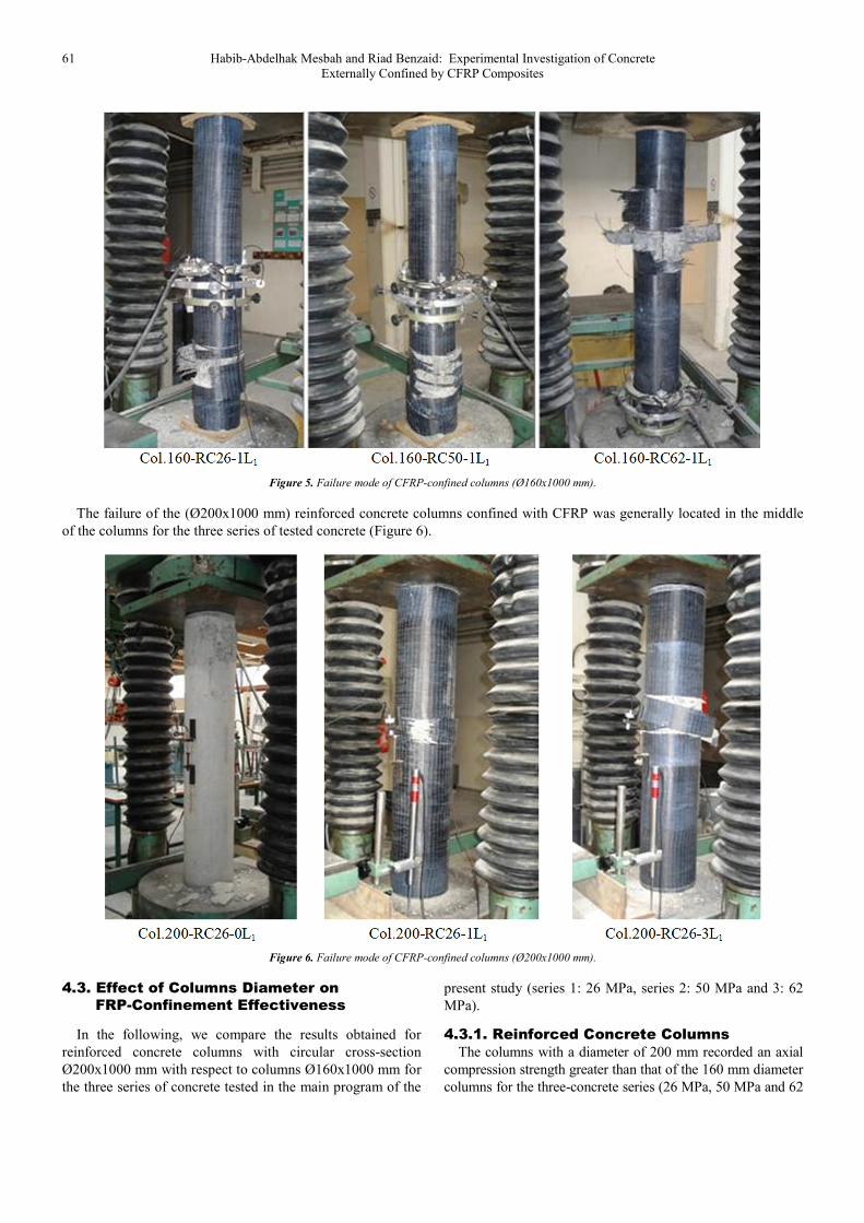
61 Habib-Abdelhak Mesbah and Riad Benzaid: Experimental Investigation of Concrete
Externally Confined by CFRP Composites
Figure 5. Failure mode of CFRP-confined columns (Ø160x1000 mm).
The failure of the (Ø200x1000 mm) reinforced concrete columns confined with CFRP was generally located in the middle
of the columns for the three series of tested concrete (Figure 6).
Figure 6. Failure mode of CFRP-confined columns (Ø200x1000 mm).
4.3. Effect of Columns Diameter on
FRP-Confinement Effectiveness
In the following, we compare the results obtained for
reinforced concrete columns with circular cross-section
Ø200x1000 mm with respect to columns Ø160x1000 mm for
the three series of concrete tested in the main program of the
present study (series 1: 26 MPa, series 2: 50 MPa and 3: 62
MPa).
4.3.1. Reinforced Concrete Columns
The columns with a diameter of 200 mm recorded an axial
compression strength greater than that of the 160 mm diameter
columns for the three-concrete series (26 MPa, 50 MPa and 62
Engineering and Technology 2017; 4(5): 56-64 62
MPa). Table 3 shows that unconfined columns with a diameter
of 200 mm offer more confinement (lateral stiffness provided
by concrete) than that of columns of 160 mm. This efficiency
of the confinement of the columns Ø200x1000 mm with
respect to that of Ø160x1000 mm decreases with the
compressive strength of the concrete. It was of the order of
69.94% for the concrete of the series 1 (26 MPa) and only of
43.99% for the concrete of the series 3 (62 MPa).
Table 3. Axial compressive strength of RC columns (control specimens).
Concrete
Series
RC columns (f’c200 – f’c160) /
f’c160 (%) Ø 160x1000 mm Ø 200x1000 mm
1 (26 MPa) 25,59 43,49 69,94
2 (50 MPa) 44,99 62,68 39,31
3 (62 MPa) 53,14 76,52 43,99
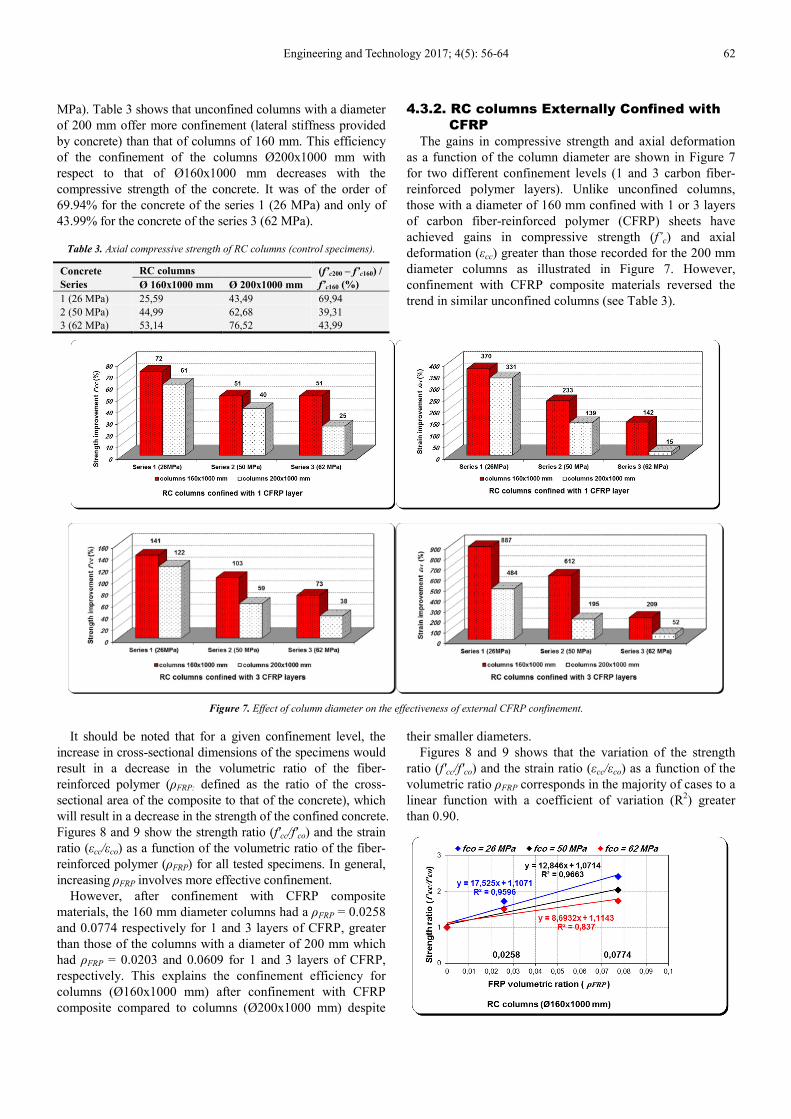
4.3.2. RC columns Externally Confined with
CFRP
The gains in compressive strength and axial deformation
as a function of the column diameter are shown in Figure 7
for two different confinement levels (1 and 3 carbon fiber-
reinforced polymer layers). Unlike unconfined columns,
those with a diameter of 160 mm confined with 1 or 3 layers
of carbon fiber-reinforced polymer (CFRP) sheets have
achieved gains in compressive strength (f’c) and axial
deformation (εcc) greater than those recorded for the 200 mm
diameter columns as illustrated in Figure 7. However,
confinement with CFRP composite materials reversed the
trend in similar unconfined columns (see Table 3).
Figure 7. Effect of column diameter on the effectiveness of external CFRP confinement.
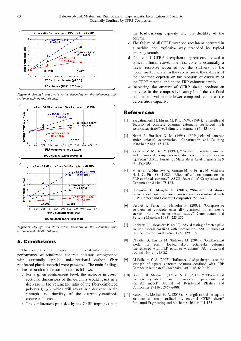
It should be noted that for a given confinement level, the
increase in cross-sectional dimensions of the specimens would
result in a decrease in the volumetric ratio of the fiber-
reinforced polymer (ρFRP: defined as the ratio of the cross-
sectional area of the composite to that of the concrete), which
will result in a decrease in the strength of the confined concrete.
Figures 8 and 9 show the strength ratio (f'cc/f'co) and the strain
ratio (εcc/εco) as a function of the volumetric ratio of the fiber-
reinforced polymer (ρFRP) for all tested specimens. In general,
increasing ρFRP involves more effective confinement.
However, after confinement with CFRP composite
materials, the 160 mm diameter columns had a ρFRP = 0.0258
and 0.0774 respectively for 1 and 3 layers of CFRP, greater
than those of the columns with a diameter of 200 mm which
had ρFRP = 0.0203 and 0.0609 for 1 and 3 layers of CFRP,
respectively. This explains the confinement efficiency for
columns (Ø160x1000 mm) after confinement with CFRP
composite compared to columns (Ø200x1000 mm) despite
their smaller diameters.
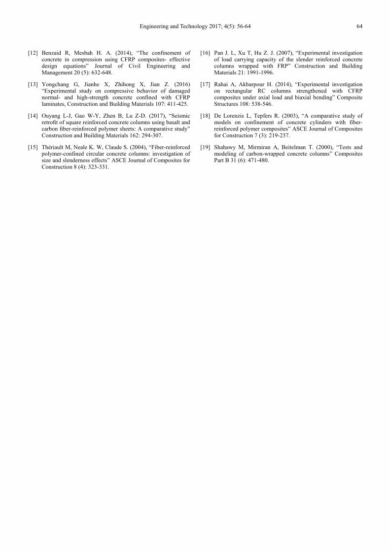
Figures 8 and 9 shows that the variation of the strength
ratio (f'cc/f'co) and the strain ratio (εcc/εco) as a function of the
volumetric ratio ρFRP corresponds in the majority of cases to a
linear function with a coefficient of variation (R2) greater
than 0.90.
63 Habib-Abdelhak Mesbah and Riad Benzaid: Experimental Investigation of Concrete
Externally Confined by CFRP Composites
Figure 8. Strength and strain ratios depending on the volumetric ratio
(columns with Ø160x1000 mm).
Figure 9. Strength and strain ratios depending on the volumetric ratio
(columns with Ø200x1000 mm).
5. Conclusions
The results of an experimental investigation on the
performance of reinforced concrete columns strengthened
with externally applied uni-directional carbon fiber
reinforced plastic material were presented. The main findings
of this research can be summarized as follows:
a. For a given confinement level, the increase in cross-
sectional dimensions of the columns would result in a
decrease in the volumetric ratio of the fiber-reinforced
polymer (ρFRP), which will result in a decrease in the
strength and ductility of the externally-confined-
concrete columns.
b. The confinement provided by the CFRP improves both
the load-carrying capacity and the ductility of the
column.
c. The failure of all CFRP wrapped specimens occurred in
a sudden and explosive way preceded by typical
creeping sounds.
d. On overall, CFRP strengthened specimens showed a
typical bilinear curve. The first zone is essentially a
linear response governed by the stiffness of the
unconfined concrete. In the second zone, the stiffness of
the specimen depends on the modulus of elasticity of
the CFRP material and on the FRP volumetric ratio.
e. Increasing the amount of CFRP sheets produce an
increase in the compressive strength of the confined
column but with a rate lower compared to that of the
deformation capacity.
References
[1] Saadatmanesh H, Ehsani M. R, Li MW. (1994), “Strength and ductility of concrete columns externally reinforced with composites straps” ACI Structural journal 9 (4): 434-447.
[2] Nanni A, Bradford N. M. (1995), “FRP jacketed concrete under uniaxial compression” Construction and Building Materials 9 (2): 115-124.
[3] Karbhari V. M, Gao Y. (1997), “Composite jacketed concrete under uniaxial compression-verification of simple design equations” ASCE Journal of Materials in Civil Engineering 9 (4): 185-193.
[4] Mirmiran A, Shahawy A, Samaan M, El Echary M, Mastrapa H. J. C, Pico O. (1998), “Effect of column parameters on FRP-confined concrete” ASCE Journal of Composites for Construction 2 (4): 175-185.
[5] Campione G, Miraglia N. (2003), “Strength and strains capacities of concrete compression members reinforced with FRP” Cement and Concrete Composites 25: 31-41.
[6] Berthet J, Ferrier E, Hamelin P. (2005), “Compressive behavior of concrete externally confined by composite jackets- Part A: experimental study” Construction and Building Materials 19 (3): 223-232.
[7] Rochette P, Labossière P. (2000), “Axial testing of rectangular column models confined with Composites” ASCE Journal of Composites for Construction 4 (3): 129-136.
[8] Chaallal O, Hassen M, Shahawy M. (2003), “Confinement model for axially loaded short rectangular columns strengthened with FRP polymer wrapping” ACI Structural Journal 100 (2): 215-221.
[9] Al-Salloum Y. A. (2007), “Influence of edge sharpness on the strength of square concrete columns confined with FRP Composite laminates” Composite Part B 38: 640-650.
[10] Benzaid R, Mesbah H, Chikh N. E. (2010), “FRP-confined concrete cylinders: axial compression experiments and strength model” Journal of Reinforced Plastics and Composites 29 (16): 2469-2488.
[11] Benzaid R, Mesbah H. A. (2013), “Strength model for square concrete columns confined by external CFRP sheets” Structural Engineering and Mechanics 46 (1): 111-135.
Engineering and Technology 2017; 4(5): 56-64 64
[12] Benzaid R, Mesbah H. A. (2014), “The confinement of concrete in compression using CFRP composites- effective design equations” Journal of Civil Engineering and Management 20 (5): 632-648.
[13] Yongchang G, Jianhe X, Zhihong X, Jian Z. (2016) “Experimental study on compressive behavior of damaged normal- and high-strength concrete confined with CFRP laminates, Construction and Building Materials 107: 411-425.
[14] Ouyang L-J, Gao W-Y, Zhen B, Lu Z-D. (2017), “Seismic retrofit of square reinforced concrete columns using basalt and carbon fiber-reinforced polymer sheets: A comparative study” Construction and Building Materials 162: 294-307.
[15] Thériault M, Neale K. W, Claude S. (2004), “Fiber-reinforced polymer-confined circular concrete columns: investigation of size and slenderness effects” ASCE Journal of Composites for Construction 8 (4): 323-331.
[16] Pan J. L, Xu T, Hu Z. J. (2007), “Experimental investigation of load carrying capacity of the slender reinforced concrete columns wrapped with FRP” Construction and Building Materials 21: 1991-1996.
[17] Rahai A, Akbarpour H. (2014), “Experimental investigation on rectangular RC columns strengthened with CFRP composites under axial load and biaxial bending” Composite Structures 108: 538-546.
[18] De Lorenzis L, Tepfers R. (2003), “A comparative study of models on confinement of concrete cylinders with fiber-reinforced polymer composites” ASCE Journal of Composites for Construction 7 (3): 219-237.
[19] Shahawy M, Mirmiran A, Beitelman T. (2000), “Tests and modeling of carbon-wrapped concrete columns” Composites Part B 31 (6): 471-480.

![Valve terminal MPA-S - Festo USA · Pneumatic components description Valveterminalwith MPA-Spneumatics Type: MPA-FB MPA-CPI MPA-MPM-…and MPA-ASI-… 534241 1309f [8028624] Valve](https://img.pdfslide.net/doc/110x75/5c5bd85409d3f236368c6efe/valve-terminal-mpa-s-festo-usa-pneumatic-components-description-valveterminalwith.jpg)


![Ventilterminal MPA−L...Pneumatik MPA−L Ventilterminal Typ: MPA−L−MPM−VI MPA−L−FB−VI Beskrivning 556 358 sv 1008NH [722 283] Ventilterminal MPA−L. ... betyder att](https://img.pdfslide.net/doc/110x75/60912199dc0d2a008521a11b/ventilterminal-mpaal-pneumatik-mpaal-ventilterminal-typ-mpaalampmavi.jpg)