Embed Size (px)
Citation preview
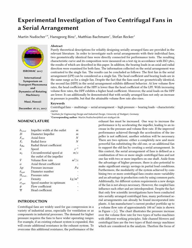
Experimental Investigation of Two Centrifugal Fans ina Serial ArrangementMartin Nudischer1*, Hansgeorg Binz1, Ma�hias Bachmann1, Stefan Recker1
SYM
POSI
A
ON ROTATING MACHIN
ERY
ISROMAC 2017
InternationalSymposium on
Transport Phenomenaand
Dynamics of RotatingMachinery
Maui, Hawaii
December 16-21, 2017
AbstractPurely theoretical descriptions for reliably designing serially arranged fans are provided in therelevant literature. In order to investigate such serial arrangements with their individual fans,two geometrically identical fans were directly connected for performance tests. The resultingcharacteristic curve and its composition were measured on a test rig in accordance with ISO 5801,the results of which are described in this paper. In addition, the bearing loads in an axial and radialdirection were examined for both fans. The information collected on the serial arrangement wascontrasted to the single fan. The results can be concluded as follows: The �rst fan in the serialarrangement (LPF) can be considered as a single fan. The head coe�cient and bearing loads are inthe same range as for a single fan. Despite the fact that the fans used are geometrically identical,the second fan (HPF) in the serial arrangement exhibits di�erent behavior. At low volume �owrates, the head coe�cient of the HPF is lower than the head coe�cient of the LPF. With increasingvolume �ow rates, the HPF exhibits a higher head coe�cient. Moreover, the axial loads on the HPFare lower. It can additionally be demonstrated that with serially arranged fans not only an increasein pressure is possible, but that the attainable volume �ow rate also rises.KeywordsCentrifugal fans — multistage — serial arrangement — high pressure — bearing loads —characteristiccurve1Institute for Engineering Design and Industrial Design, University of Stu�gart, Germany*Corresponding author: [email protected]�gart.de
NOMENCLATURE
b2,tot Impeller width at the outlet mD Diameter Impeller mFax Axial force NFr Radial force NkRu Radial thrust coe�cient -n Speed s−1
u2 Circumferential speed at m/sthe outlet of the impeller
ÛV Volume �ow rate m3/sα Axial thrust coe�cient -∆p Pressure increase Paδopt Diameter number -Πstat . Pressure ratio -ρ Density kg/m3
σopt Speed number in optimum -φ Flow coe�cient -Ψ Head coe�cient -
INTRODUCTIONCentrifugal fans are widely used for gas compression in avariety of industrial areas, especially for ventilation or ascomponents in industrial processes. The demand for higherpressure requires the fans to have wider operating ranges.For example, if an existing exhaust system is expanded, thiswill create additional resistance in the exhaust system. Toovercome this additional resistance, the performance of the
exhaust fan must be increased. One way to increase theperformance is by accelerating the impeller, leading to an in-crease in the pressure and volume �ow rate. If the improvedperformance achieved through the acceleration of the im-peller is not su�cient, another solution will be necessary.There are two options: either a completely new and morepowerful fan substituting the old one, or an additional fanto support the old fan by creating a serial arrangement. Inthis context, the serial arrangement of fans is de�ned as acombination of two or more single centrifugal fans and notone fan with two or more impellers on one shaft. Aside fromthe advantage of higher pressure, there is also potential tomake signi�cant energy savings in partial load conditions.Furthermore, the modularity of the system achieved by com-bining two or more centrifugal fans creates more variabilityand an advantage in production costs by using common parts.Additionally, for di�erent system requirements a new designof the fan is not always necessary. However, the coupled fansin�uence each other and are interdependent. Despite the factthat only few scienti�c investigations have been conductedinto serially arranged centrifugal fans, many performed se-rial arrangements can already be found incorporated intoplants. A fan manufacturer’s current product portfolio up toa volume �ow rate of approximately 100 m3/min is shownin Figure 1 [1]. The chart illustrates the pressure increaseover the volume �ow rate for two types of turbo-machineswith di�erent working principles. Side channel blowers andcentrifugal fans are the two types of �uid energy machineswhich are considered in the analysis. Therfore the focus of

Experimental Investigation of Two Centrifugal Fans in a Serial Arrangement — 2/9
the product analysis is on the low cost sector and disregardsexpensive special solutions such as high-drive turbochargersor similar.
PressureincreaseΔp[kPa]
Volume flow-rate V [m³/min].0
10
20
30
40
50
10 20 30 40 50 60 70 80 90 100
sidechannelblowers
single-stage centrifugal fans
multi-stage centrifugal fans
Figure 1. Product portfolio analysis [1]
As shown in Figure 1, for high pressure at low volume�ow rates side channel blowers are used. With increasing de-mands in terms of volume �ow rate, the available pressure ofthe side channel blowers drops dramatically. After exceedingthe maximum volume �ow rate of approximately 30 m3/min,side channel blowers cannot be used anymore. Centrifugalfans are used to meet the demand for high volume �ow rates.The disadvantage of centrifugal fans in comparison to sidechannel blowers is the lower attainable pressure increase.The gap in the characteristic map for demands for high pres-sures levels and simultaneously high volume �ow rates isobvious. By combining two or more centrifugal fans in se-ries, the available pressure can be increased. Moreover, theine�cient side channel blowers with an energy e�ciency ofalmost 50 % [2] can be replaced by multi-stage centrifugalfans in order to save energy. Centrifugal fans can help to re-duce energy consumption with an e�ciency of a single-stageup to 85 % [3]. In addition, a serial system with two or morefans is able to disconnect the fans independently, for exam-ple under partial load conditions. The potential for seriallyarranged fans is enormous considering the attainable perfor-mances in terms of pressure and volume �ow rate. Dependingon the requirements for serially arranged fans, only two ormore centrifugal fans and appropriate connecting pipes arerequired in general. This connection leads mechanically toa serial arrangement. However, the e�ects arising from thisconnection are still unknown and there is no scienti�callybased approach for dimensioning serially arranged fans. Thissystem of two or more fans is also an oscillating system withtwo or more initiating vibration sources. The key question isthus: What are the changes incurred by directly connectingtwo or more fans compared to a single fan? This paper isan initial step toward identifying the correlations within thesystem in terms of the characteristic curve and bearing loads.
1. STATE OF THE ART
Over the decades, a lot of scienti�c research has been con-ducted into single centrifugal fans, see for example [4], [5],[6] or [7]. Due to the feasible strength of the materials used(usually steel or aluminum), the peripheral speed is limitedto approximately 150 m/s for welded or riveted sheet-metalimpellers [8]. The available pressure increase and volume�ow rate are thus limited with a single centrifugal fan. Sub-stituting the impeller material for high-strength materialsenables higher peripheral speeds but also leads to excessiveproduction costs.Only short theoretical descriptions are given in the literaturefor centrifugal fans with regard to the serial connection oftwo or more fans [4], [7]. Considerable changes incurred bycoupling two or more fans cannot be identi�ed. Eck theo-retically described the resulting characteristic curve of morethan one centrifugal fan serially arranged through super-position of the single characteristic curves [7]. The totalpressure increase at a de�ned volume �ow rate is thereforemultiplied by the number of coupled fans. Trautmann et al.[9] and Banzhaf [10] described failures in power plants inwhich more than one fan is installed within the pipe system.However, the focus in these publications was not on the fansand their in�uence on each other. This investigation wasconducted into the adjustment settings for the single fans inorder to prevent damages to the ventilation system. Carolusinvestigated the phenomena of the rotating stall and surge offans in systems with two centrifugal fans [8]. Rotating stalland surge are a kind of unsteady �ow occurring in fans at lowvolume �ow rates. The focus of this investigation was on theincidence and cause of these phenomena. Schulze-Dieckho�outlined how de�ned control interventions in�uence the be-havior of serially arranged fans at non-stationary operatingpoints [11].Axial fans or gas turbines in a multi-stage arrangement arewell understood and comprise the state of the art. Thereare numerous design methods and instructions for reliablydesigning multistage axial fans and turbines [3]. Due to thedi�erent operating principles of those rotating machines, theknowledge cannot be transferred to centrifugal fans. Theserial operating mode is widespread in pumps. However, theargument in favor of multi-stage pumps is not necessarilyto gain more pressure: In pumps, the phenomenon of cavi-tation occurs when the local pressure drops too far, whichleads to the pump being damaged due to the formation andsubsequent collapse of vapor bubbles [12]. To avoid thisphenomenon pumps are set to serial operation mode. Conse-quently, neither the knowledge of pumps nor axial fans canbe transferred to the design of serially arranged centrifugalfans. As already mentioned, the attainable ratios of volume�ow rate and pressure increase are limited by the peripheralspeed of the impeller. Moreover, the required input power isdirectly proportionate to the speed increase. Eight times asmuch power is required to operate the fan at twice the speed.According to literature, the performance of serially arrangedfans can be approximated by multiplying the total pressure

Experimental Investigation of Two Centrifugal Fans in a Serial Arrangement — 3/9
increase at a de�ned volume �ow rate by the number of cou-pled devices. In theory, serial arrangements never show anincrease in volume �ow rate above the maximum �ow rateof the implemented single fans [4], [5], [7].Figure 2 shows a typical characteristic curve of a centrifugalfan with pressure increase over volume �ow rate labelled as"Fan 1". By accelerating the impeller from rotational speed n1
TotalpressureincreaseΔp
Volume flow-rate V.
Low systemresistance
fan 1, n1
fan 1, n2 (> n1)
High system resistance2 x fan 1, each with n2
op 1
op 2
op 3
op 4
op 5
op 6
Figure 2. Characteristic curves of a single fan and seriallyarranged fans [7]
to n2, the pressure increases quadratically with the quotient(n2/n1)2. The volume �ow rate rises linearly. Generally, thefan forms part of a larger system, connected on either thesuction or the pressure side or both. The connected systemconstitutes an obstruction for the fan which can be simpli-�ed as the system resistance curve. The intersection of thefan characteristic curve and system resistance curve is theoperating point (op) of the fan. This volume �ow rate �owsthrough the system at the de�ned pressure. There is only aminor gain in pressure increase for lower system resistancecurves through higher rotational speeds (op 1 to op 2). Thehigher the system resistance curve, the higher the increasein pressure (op 4 to op 5) [4]. Nevertheless, two or more fanscan be arranged in a serial operating mode to increase thepressure even further. Especially at high system resistancesthe increase in available pressure is enormous (change in op 5to op 6). However, the changes coming up through the directconnection and the additional compression are unknown. If,for example, the summarized pressure increase is unequallydistributed across the di�erent stages (with two or more iden-tical fans at the same rotational speed), this will result in achange in pressure distribution in the housing of each fan.These di�erent pressure distributions lead to volatile bear-ing forces and thus altered service life expectations, not tomention higher maintenance rates. To summarize, there areonly few scienti�c contributions dealing with more than onefan in a serial arrangement. However, the focus in these con-tributions is either on �ow phenomena such as rotating stallor surge or the correct action in the event of malfunctions.For this reason, the direct connection of two centrifugal fans
will be examined in detail in order to �ll the gap in insu�-cient design guidelines for serially arranged fans. The focusof this investigation is on the performance of the serial ar-rangement and the changes resulting from direct connection.Bearing loads will be assessed in addition to the performancetests.
2. TEST RIGTwo centrifugal fans are required for the detailed experi-mental examination of the serial arrangement. All installedfans (low-pressure, high-pressure and single fan) are geo-metrically identical so as to avoid distortion due to designdi�erences. The speci�cations of the fan are summed up inTable 1.
Table 1. Technical data of the fan
Volume �ow rate 38 m3/minTotal pressure increase 14800 PaEngine power 11 kWRotational speed 11850 min−1
Impeller diameter 240 mm
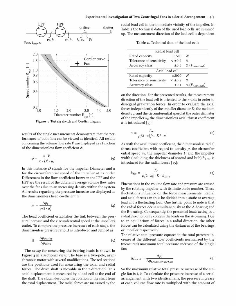
The �nal performance of the arrangement is measured ona test rig in accordance with the international standard ENISO 5801:2008 [13]. In Figure 3, a sketch of the setup is shownabove while the Cordier diagram is displayed below, in whichthe examined (single) fan is marked. The low-pressure fan(LPF) sucks the air from the atmosphere. The high-pressurefan (HPF) receives the already compressed air and compressesit further. The two fans are connected by a di�usor with itslength of 400 mm. Downstream of the arrangement, the �owrate is determined via an ori�ce plate. A shutter is placedat the end of the outlet pipe to adjust the operating point.Static pressures and temperatures are measured between thetwo fans, at the outlet of the HPF before and after the ori�ce,in addition to the ambient pressure, ambient temperatureand humidity. The Cordier diagram establishes the linkbetween the volume �ow rate ÛV , the pressure increase ∆pand the diameter of the impeller D and the speed n at theoptimum e�ciency of the single fan. This link results in thedimensionless speed number and diameter number. De�nedas follows and calculated for the examined single fan:Speed number:
σopt = 2 ·√π · n ·
√ ÛV(2 · ∆p/ρ)3/2
= · · · = 0.239 (1)
Diameter number:
δopt =
√π
2· D · 4
√2∆p/ρÛV2 = · · · = 3.811 (2)
With its high diameter number and low speed number, theexamined fan is therefore typical for radial fans. In orderto exclude any uncertainty regarding the performance ofthe fans implemented, both were measured separately. The
Experimental Investigation of Two Centrifugal Fans in a Serial Arrangement — 4/9
1.0 1.5 2.0 3.0 4.0 5.00.2
0.4
0.6
0.81.0
1.5
2.0
Speednumberσ opt[−]
Diameter number δopt[−]
Cordier curveFan
pamb, tamb, φp2, t2 t4, p4 p5
shutterorificeHPFLPF
p3, t3
Figure 3. Test rig sketch and Cordier diagram
results of the single measurements demonstrate that the per-formance of both fans can be viewed as identical. All resultsconcerning the volume �ow rate ÛV are displayed as a functionof the dimensionless �ow coe�cient φ:
φ =4 · ÛV
π · D2 · u2(3)
In this instance D stands for the impeller Diameter and ufor the circumferential speed of the impeller at its outlet.Di�erences in the �ow coe�cient between the LPF and theHPF are the result of the di�erent average volume �ow ratesover the fans due to an increasing density within the system.All results regarding the pressure increase are displayed asthe dimensionless head coe�cient Ψ:
Ψ =∆pt
ρ/2 · u22(4)
The head coe�cient establishes the link between the pres-sure increase and the circumferential speed at the impellersoutlet. To compare the pressure increases of each stage, thedimensionless pressure ratio Π is introduced and de�ned as:
Π =∆poutlet∆pinlet
(5)
The setup for measuring the bearing loads is shown inFigure 4 in a sectional view. The base is a two-pole, asyn-chronous motor with several modi�cations. The red sectionsare the positions used for measuring the axial and radialforces. The drive shaft is movable in the z-direction. Thisaxial displacement is measured by a load cell at the end ofthe shaft. The clutch decouples the rotation of the shaft fromthe axial displacement. The radial forces are measured by the
radial load cell in the immediate vicinity of the impeller. InTable 2 the technical data of the used load cells are summedup. The measurement direction of the load cell is dependent
Table 2. Technical data of the load cells
Radial load cellRated capacity ±1500 NTolerance of sensitivity < ±0.2 %Accuracy class ±0.3 % (Fnominal)
Axial load cellRated capacity ±2000 NTolerance of sensitivity < ±0.2 %Accuracy class ±0.1 % (Fnominal)
on the direction. For the presented results, the measurementdirection of the load cell is oriented to the x-axis in order todisregard gravitation forces. In order to evaluate the axialforces independently of the impeller diameter D, the mediumdensity ρ and the circumferential speed at the outer diameterof the impeller u2 the dimensionless axial thrust coe�cientα is introduced [5]:
α =Fax
ρ/2 · u22/4 · D2 · π(6)
As with the axial thrust coe�cient, the dimensionless radialthrust coe�cient with regard to density ρ, the circumfer-ential speed u2, the impeller diameter D and the impellerwidth (including the thickness of shroud and hub) b2,tot isintroduced for the radial forces [15]:
kRu =Fr
ρ/2 · u22 · D · b2,tot(7)
Fluctuations in the volume �ow rate and pressure are causedby the rotating impeller with its �nite blade number. These�uctuations in�uence on the force measurements. Radialand axial forces can thus be divided into a static or averageload and a �uctuating load. One further point to note is thatthe radial forces occur simultaneously at the A-bearing andthe B-bearing. Consequently, the presented loads acting in aradial direction only contain the loads on the A-bearing. Dueto an equilibrium of forces in a radial direction, the otherforces can be calculated using the distances of the bearingsor impeller respectively.The relative total pressure equates to the total pressure in-crease at the di�erent �ow coe�cients normalized by the(measured) maximum total pressure increase of the singlefan:
∆pt,rel =∆pt
∆pt,max,single f an(8)
So the maximum relative total pressure increase of the sin-gle fan is 1, 0. To calculate the pressure increase of a serialarrangement with two identical fans, the pressure increaseat each volume �ow rate is multiplied with the amount of

Experimental Investigation of Two Centrifugal Fans in a Serial Arrangement — 5/9
Housing
Load cell (axial)
Impeller
Load cell (radial)
Clutch
B bearing
A bearingz
y
xx
y
zFigure 4. Measurement of bearing loads in sectional view [14]
fans in the arrangement. According to the relevant literaturethe maximum relative total pressure increase of a two stagedcentrifugal arrangement is 2.0. A detailed description for themeasurement uncertainties can be found in [13], [16], [17]and [18]. The estimation of the uncertainties are stated inTable 3. The determination of the direction of forces is as
Table 3. List of uncertainties
Static pressure ±1.4 %Volume �ow rate ±2.0 %Axial force ±2.6 %Radial force ±3.6 %
follows: Axial forces are positive in a positive z-direction andradial forces are positive in a negative x-axis.
3. RESULTSThe results are presented in two sections. The �rst part showsthe performance, namely the pressure-to-volume characteris-tics of the serially arranged fans in contrast to the single fan.The second section focuses on the resulting bearing loads inaxial and radial direction.
3.1 Performance of the Serial ArrangementAccording to the relevant literature the performance of theserial arrangement is calculated by doubling the total pres-sure at each volume �ow rate. This is illustrated in Figure 5with the relative total pressure against the �ow coe�cient.
As can be seen from the graph, the maximum of the totalpressure increase of the single fan is measured at a �owcoe�cient of approx. 0.04. The calculation for the serialarrangement based on the single fan results in the blackdashed line with the maximum relative total pressure of2.0. The maximum �ow coe�cient of the single fan and the
0 0.05 0.1 0.150
0.5
1.0
1.5
2.0
Flow coefficient φ [−]
Rel
ativ
e to
tal p
ress
ure
∆p
t,rel [−
]
Single fanSerial fansCalculation
Figure 5. Relative total pressure against �ow coe�cient
calculated serial arrangement remains unchanged at close to0.16.The measured results of the serially arranged fans di�er insome respects from the described calculated values. At low�ow coe�cients the measured relative total pressures arelower than the calculated ones. A possible reason couldbe, that at low �ow coe�cients the density of the air getslower at the inlet of the high pressure fan (compared to thedensity at the inlet of the low pressure fan) through the hightemperatures. The density could also be the reason for thehigher relative total pressure at �ow coe�cients between0.01 and 0.10.
Between a �ow coe�cient of 0.01 and 0.10 the measuredpressure increases are higher until both curves are relativelyequal at approx. 0.01. At �ow coe�cients higher than 0.01the measured pressure increases are higher than the calcu-lated ones and an increase in the maximum �ow coe�cient ofover 0.16 is possible. The measurement indicates an increase

Experimental Investigation of Two Centrifugal Fans in a Serial Arrangement — 6/9
in the maximum �ow coe�cient. Another noteworthy pointis that the di�erence of the relative total pressure betweenthe calculation and the measurement tends to increase with arising �ow coe�cient at �ow coe�cients > 0.10. This leadsto the conclusion that the maximum �ow coe�cient is higherthan expected. The maximum attainable increase in the �owrate of the serial arrangement is thus also higher.To clarify these points, the two fans in the serial arrangementare considered separately. The chart in Figure 6 shows thehead coe�cient ψ against the �ow coe�cient φ of the LPF,the HPF and the single fan. The shape of the curve of theLPF (red) di�ers from that of the HPF (black). Particularly
0 0.05 0.1 0.150.4
0.6
0.8
1
1.2
1.4
Flow coefficient φ [−]
Hea
d co
effic
ient
ψ [−
]
Single fanLPFHPF
Figure 6. Head coe�cient against �ow coe�cient of LPF and HPF
at low �ow coe�cients, the head coe�cient in the LPF ishigher than in the HPF. At lower �ow coe�cients, the in-crease in pressure is therefore delivered by the LPF. With anincreasing �ow coe�cient there is a reversal of the trend. Athigher �ow coe�cients, the head coe�cient of the HPF ishigher. Thus, despite the geometrically identical structureof both fans, their behavior di�ers. These results indicatethat both the LPF and the HPF only deliver the same headcoe�cient at one operating point. However, the blue line ofthe single fan and the red line of the LPF are almost identical.Therefore, the LPF in the serial arrangement has a compa-rable behavior to a single fan. It stands to reason that the�rst stage will not be a�ected by the downstream stages inany serial arrangement. Based on the presented data, theLPF of the serial arrangement has a behavior comparable tothe single fan in terms of performance. Therefore, the stateof the art for designing single fans can be transferred to theLPF. It is also important to note that the identi�ed e�ects onthe characteristic curve of the serial arrangement (see Figure5) are caused by the HPF. Even if the basic concept of theserially arranged fans is to increase the available pressure anincrease in the maximum volume �ow rate must be observed.A di�erent head coe�cient results in a di�erent pressure in-crease at a particular operating point. These changes result-ing in with the uneven pressure distribution and concerningthe bearing loads are evaluated in the next section.
3.2 Bearing LoadsIn order to calculate the bearing loads, durability, shaft stressesand de�ection, the radial and axial forces primarily generatedby the impeller must be known. Simpli�ed in the form ofthe non-uniform pressure distribution at the outlet of therotating impeller, radial forces are created. As already men-tioned, there is a �uctuation in the volume �ow rate andthe pressure increase caused by the rotating impeller withits �nite blade number. These �uctuations in�uence forcemeasurement. Therefore, the radial and axial forces can bedivided into a static or average load and a �uctuating load.In this case, the mean over three revolutions of the impellerin terms of the average load is presented in Figure 7 withthe radial thrust against the volume �ow rate as the dimen-sionless radial thrust coe�cient against the �ow coe�cient.The �uctuating loads (or amplitude) are shown in Figure 8.The single fan (blue) starts with a radial thrust coe�cient
0 0.05 0.10 0.15−0.5
0
0.5
1
1.5
2
2.5x 10
−4
Flow coefficient φ [−]
Rad
ial t
hrus
t coe
f. k Ru [−
]
Single fanLPFHPF
Figure 7. Averaged radial thrust coe�cient against �owcoe�cient of single fan, LPF and HPF
of almost zero. With increasing �ow coe�cients, there is anearly linear increase of the radial thrust coe�cient. The LPFstarts with a radial thrust coe�cient of less than zero andexhibits a milder increase compared to the single fan. Theradial load on the high-pressure fan is comparable to that ofthe single fan. In summary, the maximum radial thrust coef-�cients are at the highest �ow coe�cients. The amplitudeof the radial thrust coe�cient of the single fan, the LPF andthe HPF in Figure 8 �uctuates against the �ow coe�cient. Itcan be assumed that the amplitude of the radial thrust coe�-cient follows a parabolic trend with its apex in the range ofthe maximum e�ciency. The changes incurred by the serialarrangement in terms of radial forces are unremarkable. Inabsolute terms, the radial loads of the single fan and the serialarrangement are not that high compared to the loads in axialdirection.
Axial forces occur due to uneven pressure distributionson the surface of the hub and the shroud of the impellerand due to the momentum caused by the de�ection of the�ow. Figure 9 illustrates the static axial forces at di�erent

Experimental Investigation of Two Centrifugal Fans in a Serial Arrangement — 7/9
0 0.05 0.10 0.150.5
1
1.5
2
2.5
3
3.5
4x 10
−4
Flow coefficient φ [−]
Rad
ial t
hrus
t coe
f. am
p. k Ru [−
]
Single fanLPFHPF
Figure 8. Amplitude of radial thrust coe�cient against �owcoe�cient of single fan, LPF and HPF
�ow rates represented by the axial thrust coe�cient againstthe �ow coe�cient, drawn over the �ow coe�cient. Thethree di�erent visible lines represent the axial force in thesingle fan, the LPF and the HPF. The single fan (blue) starts
0 0.05 0.10 0.150.1
0.15
0.2
0.25
0.3
Axi
al th
rust
coe
f. α [−
]
Flow coefficient φ [−]
Single fanLPFHPF
Figure 9. Axial thrust coe�cient against �ow coe�cient of singlefan, LPF and HPF
with an axial thrust coe�cients of 0.25 and increases slightlyuntil an φ of 0.07 is reached. After this, there is a jump toα = 0.28 at φ = 0.08 followed by a decrease. The character-istic of the LPF (red) is comparable to that of the single fan:a moderate increase in the axial thrust coe�cient at small�ow coe�cients with a peak of α = 0.28 at φ = 0.08 and asubsequent reduction. The HPF deviates from this behavior.Only the trend of the curve is similar to the single fan andLPF. Starting with an axial thrust coe�cient of 0.20 at low�ow coe�cients, there is a slight drop with increasing �owcoe�cients. What is remarkable is the sudden increase of theaxial thrust coe�cient with its peak in the same region ofthe �ow coe�cient like those of the single fan and the LPF,but with a lower maximum of α = 0.25. With further increas-ing �ow coe�cients, the axial thrust coe�cient of the HPF
converges with the others. There is a reduction in the axialforces in the HPF in serial arrangements. This reduction isalmost 20 % at certain operating points. At �ow coe�cientshigher than 0.10 the loads begin to converge with each other.The in�uence of the momentum is also visible with regardto the trend of the axial thrust coe�cient at high �ow coe�-cients. For the �uctuating loads presented in Figure 10, it canbe assumed that the �uctuation of the axial force remainsconstant as the �ow rate increases.To investigate the traceable reduction of axial forces in the
0 0.05 0.10 0.150.025
0.03
0.035
0.04
0.045
0.05
Flow coefficient φ [−]
Axi
al th
rust
coe
f. am
p. α [−
]
Single fanLPFHPF
Figure 10. Amplitude of axial thrust coe�cient against �owcoe�cient of single fan, LPF and HPF
HPF, the static pressure ratio is examined against the �owcoe�cient in Figure 11. Here, the pressure ratio is de�ned asthe quotient of the static pressure at the outlet to the staticpressure of the inlet on the relevant fan. Obviously, at low�ow coe�cients, the pressure ratio by the LPF is higher. Withincreasing �ow coe�cients the static pressure increase ofthe LPF drops more rapidly than that of the HPF. There isan intersection of the curves at a �ow coe�cient of approxi-mately 0.075. Up to this point, the pressure ratio of the HPF ishigher. The lower pressure ratio at �ow coe�cients of 0.075
0 0.05 0.10 0.151.00
1.05
1.10
1.15
1.20
Flow coefficient φ [−]
Pre
ssur
e ra
tio Π
stat
. [−]
LPFHPF
Figure 11. Pressure ratio over �ow coe�cient of LPF and HPF

Experimental Investigation of Two Centrifugal Fans in a Serial Arrangement — 8/9
and below could contribute to the lower axial thrust coe�-cient in these �ow coe�cient ranges. There is a di�erence inthe radial and axial forces in a serial arrangement dependingon the fan being observed. The LPF has loads in a radialand axial direction comparable to the single fan. The loadsthat the HPF has in a radial direction are also comparableto the single fan. However, the axial loads in the HPF arelower compared to the single fan over a wide range of �owcoe�cients.
4. CONCLUSIONIn the current paper, the in�uence of two radial fans in a se-rial arrangement on the characteristic curve and the resultinge�ects on the bearing forces were examined. Both fans aregeometrically identical centrifugal fans which were directlyconnected to each other and run at the same speed. Thetheoretically described behavior of the serial arrangementdi�ers from the measured results. The measured pressureincrease at de�ned volume �ow rates is equivalent to or evenhigher than the calculated values (according to literature)which can be obtained by doubling the total pressure of thesingle fan. Another remarkable point is that the pressurenot only increases, but there is also a higher �ow coe�cientor a higher volume �ow rate respectively. The two fans inthe serial arrangement, the low-pressure fan (LPF) and thehigh-pressure fan (HPF) show deviations in their characteris-tics as well as their bearing loads. The LPF displays behaviorcomparable to that of a single fan in its characteristics aswell as in the occurring loads. This statement could be vali-dated for the characteristic curve and the loads. It stands toreason that the �rst stage will not be a�ected by the down-stream stages in any serial arrangement. The state of the artof designing single fans can therefore be transferred to thelow-pressure stage of a multi-stage arrangement. Despite theidentical geometric parameters of the HPF, its characteristiccurve has a di�erent shape. At low �ow coe�cients, the headcoe�cient is lower in comparison to the LPF. The pressureincrease is thus unevenly composed. Only at one operatingpoint is the pressure increase equally distributed across bothfans. For lower �ow coe�cients, the main portion of thepressure increase is delivered by the LPF. With increasing�ow coe�cients, however, there is a reversal of the trend. Athigher volume �ow rates, the ratio of the pressure increaseis higher for the HPF. So, despite the geometrically equaldesign of both fans, their behavior di�ers. A di�erent pres-sure distribution also leads to a change in the loads of thebearings. The axial loads at the HPF in particular decrease incomparison to the single fan. Thus, for future design workon serial arrangements, the focus must be speci�cally on theHPF.
5. OUTLOOKThese results show that the theoretically described charac-teristic curve di�ers from the measured one. The HPF inparticular exhibits a signi�cant change in behavior in terms
of the characteristic curve and bearing loads. The focus willtherefore be placed on the HPF to clarify these changes viacomputational �uid dynamics in combination with additionalexperiments.
REFERENCES[1] Elektror [online]. Available at:
http://www.elektror.de/en/products. Accessed 05/01/2017.[2] A. Krake and K. Fiedler, editors. Laser-2-Focus Mea-
surements and Flow Visualisation within the Rotating Ro-tor and the Side Channel of a Side Channel Compressor,Hawaii, 2002.
[3] A. Starck, A. Mühlbauer, and C. Kramer. Handbook ofThermoprocessing Technologies. Vulkan Verlag, 2 edition,2012.
[4] W. Bohl. Ventilatoren: Berechnung Konstruktion, Versuch,Betrieb. Vogel Fachbuch, 1 edition, 1983.
[5] L. Bommes, J. Fricke, and R. Grundmann. Ventilatoren.Vulkan Verlag, 2 edition, 2002.
[6] T. Carolus. Ventilatoren: Aerodynamischer Entwurf,Schallvorhersage, Konstruktion. Vieweg+Teubner Verlag,3 edition, 2013.
[7] B. Eck. Ventilatoren: Entwurf und Betrieb der Radial-,Axial- und Querstromventilatoren. Springer, Berlin, 6edition, 2003.
[8] T. Carolus. Theoretische und experimentelle Untersuchungdes Pumpens von lufttechnischen Anlagen mit Radialven-tilatoren. University of Karlsruhe, 1984.
[9] G. Trautmann and K. Jun. Leittechnische Maßnah-men zur Vermeidung unzulässiger Rauchgasdruecke beiNachruestung von Dampferzeugern mit REA und DE-NOX. Jahrbuch der Dampferzeugungstechnik, 6:651–667,1988.
[10] H.-U. Banzhaf. Anlagespezi�sche Fragen bei Ventila-toren in Reihenschaltung. Brennsto�, Wärme, Kraft,41:82–86, 1989.
[11] B. Schulze Dieckho�. Das instationäre Betriebsverhal-ten ungeregelter und geregelter lufttechnischer Anlagenmit einem, zwei in Reihe oder zwei parallelgeschaltetenVentilatoren, volume 7. 1999.
[12] C.E. Brennen. Hydrodynamics and cavitation of pumps.In d’Agostino L. and Salvetti M. V., editors, Fluid Dy-namics of Cavitation and Cavitating Turbopumps, pages43–167. Springer, 2007.
[13] EN ISO 5801: Industrial Fans - Performance Testing UsingStandardized Airways. 2010.
[14] S. Recker. Ganzheitliche Optimierung schnelldrehenderHochdruckventilatoren. Institutsbericht IKTD Universi-taet Stuttgart, 620, 2012.
[15] J.F. Guelich. Centrifugal pumps. Springer, 2 edition, 2010.
Experimental Investigation of Two Centrifugal Fans in a Serial Arrangement — 9/9
[16] EN ISO 5167-1: Measurement of �uid �ow by meansof pressure di�erential devices inserted in circular cross-section conduits running full - Part 1: General principlesand requirements. 2003.
[17] EN ISO 5167-2:Measurement of �uid �ow bymeans of pres-sure di�erential devices in circular cross-section conduitsrunning full - Part 2: Ori�ce plates. 2003.
[18] ISO 5168: Measurement of �uid �ow - Evaluation of un-certainties. 2005.


![Investigations on the performance of centrifugal pumps in … · 2017-03-02 · scribes the inlet characteristics of a pump [5]. ... Investigation on the performance of centrifugal](https://img.pdfslide.net/doc/110x75/5e86bc07398b760d3a42aab5/investigations-on-the-performance-of-centrifugal-pumps-in-2017-03-02-scribes-the.jpg)