Embed Size (px)
Citation preview
Send Orders of Reprints at [email protected]
The Open Civil Engineering Journal, 2013, 7, 93-100 93
1874-1495/13 2013 Bentham Open
Open Access
Experimental Study on Effects of Type and Replacement Ratio of Fly Ash on Strength and Durability of Concrete
Hongzhu Quan1,* and Hideo Kasami2
1School of Civil Engineering, Qingdao Agricultural University, Qingdao, Shandong, 266109, China 2Japan Association for Building Research Promotion, Tokyo, 108-0014, Japan
Abstract: This paper presents the test results of a series of experimental studies on the effects of type and replacement ra-tio of fly ash on strength and durability of concrete. 3 types of fly ashes are used in this research, the specific surface area of which are 5070 cm2/g, 3760 cm2/g and 1970 cm2/g, respectively. They satisfy the requirement of Type-1, Type-2 and Type-4 fly ashes in Japanese Industrial Standard. Ordinary Portland cement, river sand, crushed sandstone, water reducer and air entraining agent are used as well. The results indicate that drying shrinkage of concrete is reduced when cement is partially replaced by fly ash. Comparatively, Type-2 fly ash’s addition leads to a more effective drying shrinkage reduc-tion, and those with replacement ratios result in larger dry shrinkage reduction. Carbonation increases with the increase of replacement ratio of fly ash, and concrete with Type-1 fly ash has higher carbonation than those with Type-2 and Type-4 fly ashes. The carbonation rate is found to be linear with water cement ratio regardless of replacement ratio of fly ash. Du-rability factor decreases with the replacement ratio of fly ash after 300 freezing and thawing cycles. Also, durability factor of concrete containing Type-1 and Type-2 fly ashes with replacement ratio of 25% to 55% is higher than 80%. However, those with Type-4 fly ash show lower durability factor after 300 cycles. Concretes with 70% replacement of fly ash are not durable in spite of the type of fly ash or specific surface area.
Keywords: Carbonation, Compressive strength, Drying shrinkage, Fly ash, Freezing and thawing, Replacement ratio.
1. INTRODUCTION
Fly ash in Japan has been rapidly increasing with the increase of coal-fired power stations. The annual production of fly ash is 10 million tons [1]. Though approximately 80% of fly ashes are utilized mainly in cement industries, only 2.4% of fly ash is used as admixture material for concrete, including composite cement and concrete. In addition, more and more ground granulated blast-furnace slag is used in concrete partially replacing cement for the purpose of reduc-ing material costs and avoiding cracks in mass concrete. Fur-thermore, the addition of such kinds of supplementary ce-mentitious materials can reduce the risk of alkali-aggregate reaction, and reduces CO2 emission. The obstacles prevent-ing fly ash utilization in Japan are that the permissible re-placement ratio of fly ash is limited to 30% for structural concrete, and that only Type-1 and Type-2 fly ashes are usu-ally specified, while JIS A 6201 Japanese Industrial Stan-dard for Fly Ash Used in Conrete specifies Type-1, Type-2, Type-3, and Type-4 fly ashes. For instance, JIS R 5213 Japanese Industrial Standard for Fly Ash Cements requires that the portion of fly ash in the cementitious material is lim-ited to 30% by mass. Japanese Architectural Standard Specification JASS 5 for Reinforced Concrete Work requires
*Address correspondence to this author at the School of Civil Engineering, Qingdao Agricultural University, Qingdao, Shandong, 266109, China; Tel: +86-532-88030416; +86-13792443322; Fax: +86-532-88030411; E-mail:[email protected]
the permissible Portland cement replacement with Type-1 and Type-2 fly ash is limited to 30% by mass, and JASS 5N for Reinforced Concrete Work at Nuclear Power Plants re-quires that the cement replacement should not more than 20% by mass. Therefore, it is necessary to clarify the influ-ence of type and replacement ratio of fly ash on the strength and durability of concrete in which cement is replaced by higher volume of fly ash, so as to expand the application field of fly ash.
At present, the utilization of fly ash in Japan is defined in Type-1 and Type-2 fly ashes, and the replacement ratio is limited to 30% for structural concrete. In order to expand the application range of fly ash in structural concrete, the Type-1, Type-2, and Type-4 fly ashes are taken as re-search object in this study, and the replacement ratio increases to 70%. Meanwhile, the effects of type and re-placement ratio of fly ash on mixture proportions, fresh con-crete properties, strength development, drying shrinkage, carbonation and freezing-thawing resistance of concrete are widely discussed.
2. SCOPE OF EXPERIMENT
5 mixtures of ordinary Portland cement (OPC) concrete, of which the water cement ratio is from 38% to 75%, are designed as reference specimen. 28 mixtures of fly ash con-crete with the water binder ratio from 38% to 60% are used to test the compressive strength, drying shrinkage, carbona-tion and freezing and thawing resistance, where Portland
94 The Open Civil Engineering Journal, 2013, Volume 7 Quan and Kasami
cement is replaced by 3 types of fly ashes by ratios from 25% to 70%.
3. MATERIALS
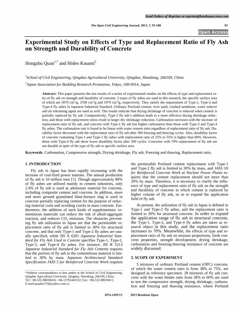
Type-1 fly ash (FA1), Type-2 fly ash (FA2) and Type-4 fly ash (FA4), from a coal-fired power plant are used. All the indexes satisfy the requirements of JIS A 6201 Japanese Industrial Standard for Fly Ash Used in Conrete. Chemical analysis and physical characteristics of fly ashes are shown in Table 1. Scanning electron micrographs of fly ashes are shown in Fig. (1). The differences among 3 fly ashes are mainly in particle size. The specific surface area of FA1, FA2 and FA4 are 5070 cm2/g, 3760 cm2/g and 1970 cm2/g, respectively.
Ordinary Portland cement with density of 3.16 g/cm3, specific surface area of 3280 cm2/g and 28 days compressive
strength of 62.0 N/mm2 is used. The coarse aggregate is a kind of crushed sandstone from Oume, and the fine aggre-gate is a kind of river sand from Oui-River. The physical properties of aggregates are shown in Table 2. The water reducer used in this research is of lignosulphonic acid type, and the air-entraining agent of anionic surfactant is used in this research.
4. MIXTURE PROPORTIONS AND DOSAGE OF AE AGENT
Mixture proportions of concretes are shown in Table 3. The target slump is 18.0 cm, and the target air content is 4.5%.
Water content of concrete containing FA1 and FA2 de-creases with the increase of fly ash dosage, while water con-tent of concrete increases with the addition of FA4. Air-
FA 1 FA 2 FA 4
Fig. (1). Scanning electron micrographs of fly ashes ( 1,500 times ).
Table 1. Chemical Analysis and Physical Characteristics of Fly Ashes
Chemical analysis Physical characteristics
Fineness
Strength activity of
mortar (%)
SiO2
(%)
SO3
(%)
CaO
(%)
MgO
(%)
Ka2O
(%)
Na2O
(%)
Loss on Ignition
(%)
Density (g/cm3)
Retained on 45μm sieve (%)
Specific surface
area (cm2/g)
Percent flow of mortar
(%) 28 days
91 days
FA 1 60.0 0.2 1.2 1.8 0.7 0.0 0.9 2.39 0.1 5070 114 93 111
FA 2 59.9 0.2 1.3 0.6 0.7 0.0 0.9 2.29 7.1 3760 107 84 103
FA 4 57.4 0.2 1.6 0.5 0.7 0.0 1.7 2.15 12.5 1970 104 74 86
Table 2. Physical Properties of Aggregates
Type of Aggregate
Maximum Size (mm)
Density in Oven-Dry Condition
(kg/m3 )
Absorption (%)
Bulk Density (kg/m3 )
Fineness Modulus
Coase aggregate Crushed Sandstone 20 2.70 0.51 1.58 6.69
Fine aggregate River sand 2.5 2.61 1.08 1.81 2.87
Experimental Study on Effects of Type and Replacement Ratio of Fly Ash The Open Civil Engineering Journal, 2013, Volume 7 95
entraining agent dosage increases linearly with the fly ash replacement ratio, and that of FA1 is higher than that of FA2 and FA4, which is due to adsorption of air-entraining agent to particles of fly ash.
5. EXPERMENTAL PROCEDURES
5.1. Fabrication and Curing of Test Specimens
Cylinders, 100 mm in diameter and 200 mm in height, for compression tests are cast in metal moulds in 3 layers by
Table 3. Mixture Proportion and Properties of Fresh and Hardened Concrete
Mixture Proportion (kg/m3 ) Fresh Concrete Compressive Strength (N/mm2) (Moist cured)
FA/ (C+FA)
(%)
W/ (C+FA)
(%) W/C (%)
W C FA S G Slump (cm)
Air (%) 7 28 91 182d
- 43 178 414 - 762 17.5 5.0 39.9 48.8 56.3 57.9
- 50 174 348 - 827 18.5 4.9 35.1 38.9 49.0 52.0
- 60 170 283 - 892
971
17.5 4.6 25.6 30.5 38.6 38.5 OPC 0
- 75 175 233 - 936 955 18.5 4.7 16.1 21.9 27.4 27.2
43 57 176 307 102 743 17.5 4.7 28.8 43.1 56.6 62.8 25
50 67 165 248 82 844 18.0 3.2 22.6 34.8 46.3 51.4
43 72 174 239 159 751 17.0 4.4 21.0 33.5 45.0 49.8 40
50 83 163 196 130 840
971
16.5 4.3 16.9 28.9 38.9 44.4
43 96 167 175 214 770 18.0 4.0 11.3 19.3 26.2 32.3 55
50 111 166 149 183 828 16.5 5.4 9.6 17.8 23.6 32.2
43 143 168 115 269 765 19.0 5.0 4.7 9.5 14.4 22.5
FA 1
70 50 167 164 98 230 824
955
16.5 4.6 3.5 6.9 11.6 16.8
43 57 165 288 96 791 18.0 4.3 31.2 37.9 54.8 60.8
50 67 165 248 82 840 18.5 4.5 23.0 32.8 44.5 49.9 25
60 80 161 201 67 907 17.0 4.8 15.9 24.6 34.7 39.6
38 63 170 268 179 698 19.0 4.7 28.0 39.2 53.9 58.2
43 72 163 227 152 782 18.0 4.4 21.3 31.7 44.3 50.9 40
50 83 165 198 132 824
971
18.0 4.4 15.4 26.0 36.4 41.0
38 84 167 198 242 708 19.0 4.9 17.3 27.2 38.4 43.3
43 96 163 171 208 780 19.0 5.1 12.6 21.3 31.6 42.8 55
50 111 167 150 184 815 18.0 4.8 9.3 16.4 25.5 31.5
38 127 177 140 326 633 19.0 4.7 9.2 15.0 22.7 31.8
43 143 160 112 260 777 18.5 5.4 6.0 9.6 17.3 26.6
FA 2
70
50 167 158 95 221 842
955
19.0 4.9 3.2 5.6 13.0 20.8
43 57 176 307 102 731 18.5 4.4 31.1 41.0 53.6 57.6 25
50 67 172 258 86 802 18.0 3.9 21.9 31.0 40.1 44.2
43 72 180 251 167 687 18.5 5.0 20.8 29.9 40.0 46.0 40
50 83 174 209 139 773
971
18.0 4.6 15.1 22.6 32.6 39.0
43 96 184 195 238 647 19.0 5.1 11.2 16.4 26.1 31.8 55
50 111 175 158 193 763 18.0 5.3 8.7 14.0 21.3 27.0
43 143 198 138 322 559 18.5 4.7 5.2 9.4 16.4 22.7
FA 4
70 50 167 176 106 246 738
955
16.5 5.3 3.0 5.4 10.9 18.4
96 The Open Civil Engineering Journal, 2013, Volume 7 Quan and Kasami
tamping. The specimens are demoulded at 24 hours after casting, and are cured in water at 20℃ till testing ages.
Prisms are used for drying shrinkage tests, accelerating carbonation tests, and freezing and thawing tests, the dimen-sion of which is 100mm×100mm×400mm. Prisms are cast in two layers by tamping. They are demoulded at 24 hours after casting. Then, specimens for drying shrinkage test are cured in water at 20℃ for 6 days. Those for accelerating carbonation test are cured in water at 20℃ for 28 days and in air at 20℃ for another 28 days. Prisms for freezing and thawing test are cured in water at 20℃ until the age of 28 days.
5.2. Test Method for Hardened Concrete
5.2.1. Compressive Strength Tests
Cylinders were tested at the age of 1 week, 4 weeks, 8 weeks, 13 weeks and 26 weeks at wet condition.
5.2.2. Drying Shrinkage Tests
Prisms taken from water at 7 days, and were stored at 20ºC and 60% R.H., and were measured for length change and weight loss for 26 weeks.
5.2.3. Accelerating Carbonation Tests
Prisms, moist cured for 28days and air dried for 28 days, are stored in accelerating carbonation chamber where it is in a condition of a temperature of 20℃, relative humidity of 60%, and the CO2 concentration of 5%. Carbonation depth is determined by phenolephthalein test on cleaved surface.
5.2.4. Freezing and Thawing Tests
Prisms are subjected to Freezing and thawing cycles at the age of 28 days according to JIS A 1148-2001, similar to ASTM C 666-A. Durability factors are calculated after the freezing and thawing experiment is ended.
6. TEST RESULTS AND DISCUSSIONS
6.1. Compressive Strength
Table 3 shows the test results of fresh concrete and com-pressive strength tested on specimens cured in water at 20℃.
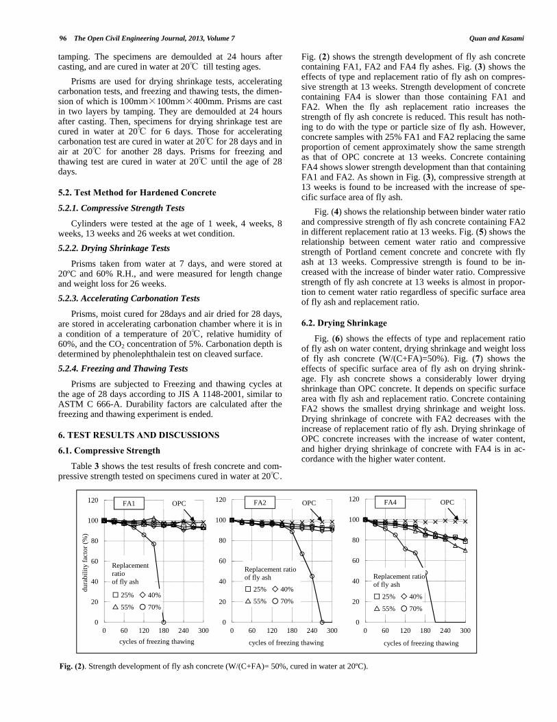
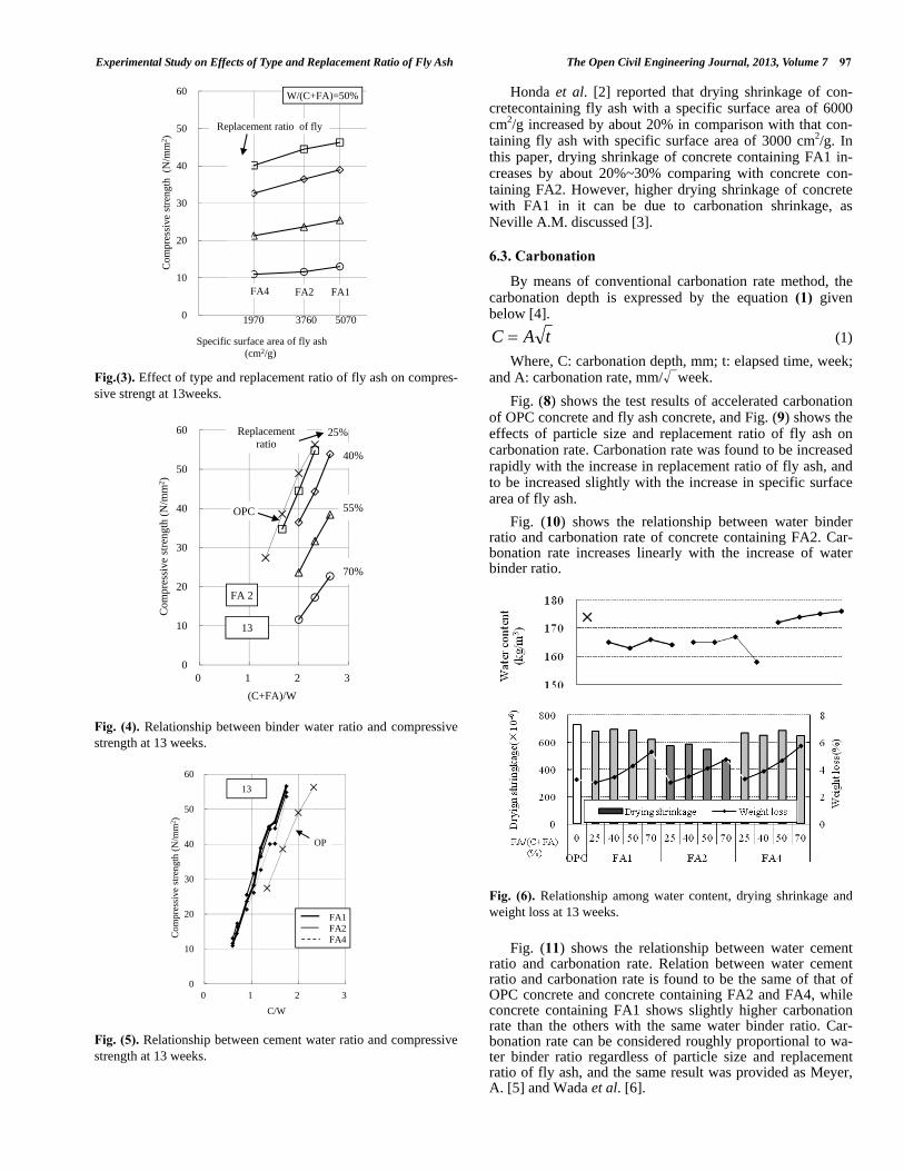
Fig. (2) shows the strength development of fly ash concrete containing FA1, FA2 and FA4 fly ashes. Fig. (3) shows the effects of type and replacement ratio of fly ash on compres-sive strength at 13 weeks. Strength development of concrete containing FA4 is slower than those containing FA1 and FA2. When the fly ash replacement ratio increases the strength of fly ash concrete is reduced. This result has noth-ing to do with the type or particle size of fly ash. However, concrete samples with 25% FA1 and FA2 replacing the same proportion of cement approximately show the same strength as that of OPC concrete at 13 weeks. Concrete containing FA4 shows slower strength development than that containing FA1 and FA2. As shown in Fig. (3), compressive strength at 13 weeks is found to be increased with the increase of spe-cific surface area of fly ash.
Fig. (4) shows the relationship between binder water ratio and compressive strength of fly ash concrete containing FA2 in different replacement ratio at 13 weeks. Fig. (5) shows the relationship between cement water ratio and compressive strength of Portland cement concrete and concrete with fly ash at 13 weeks. Compressive strength is found to be in-creased with the increase of binder water ratio. Compressive strength of fly ash concrete at 13 weeks is almost in propor-tion to cement water ratio regardless of specific surface area of fly ash and replacement ratio.
6.2. Drying Shrinkage
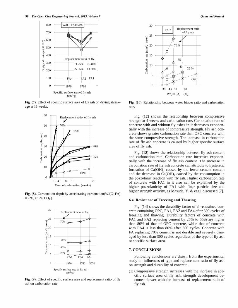
Fig. (6) shows the effects of type and replacement ratio of fly ash on water content, drying shrinkage and weight loss of fly ash concrete (W/(C+FA)=50%). Fig. (7) shows the effects of specific surface area of fly ash on drying shrink-age. Fly ash concrete shows a considerably lower drying shrinkage than OPC concrete. It depends on specific surface area with fly ash and replacement ratio. Concrete containing FA2 shows the smallest drying shrinkage and weight loss. Drying shrinkage of concrete with FA2 decreases with the increase of replacement ratio of fly ash. Drying shrinkage of OPC concrete increases with the increase of water content, and higher drying shrinkage of concrete with FA4 is in ac-cordance with the higher water content.
Fig. (2). Strength development of fly ash concrete (W/(C+FA)= 50%, cured in water at 20ºC).
0
20
40
60
80
100
120
0 60 120 180 240 300
dura
bilit
y fa
ctor
(%)
cycles of freezing thawing
FA1 OPC
Replacement ratio of fly ash
□ 25% ◇ 40%
△ 55% ○ 70%
0
20
40
60
80
100
120
0 60 120 180 240 300
cycles of freezing thawing
FA2 OPC
Replacement ratio of fly ash
□ 25% ◇ 40%
△ 55% ○ 70%
0
20
40
60
80
100
120
0 60 120 180 240 300
cycles of freezing thawing
FA4 OPC
Replacement ratio of fly ash
□ 25% ◇ 40%
△ 55% ○ 70%
Experimental Study on Effects of Type and Replacement Ratio of Fly Ash The Open Civil Engineering Journal, 2013, Volume 7 97
Fig.(3). Effect of type and replacement ratio of fly ash on compres-sive strengt at 13weeks.
Fig. (4). Relationship between binder water ratio and compressive strength at 13 weeks.
Fig. (5). Relationship between cement water ratio and compressive strength at 13 weeks.
Honda et al. [2] reported that drying shrinkage of con-cretecontaining fly ash with a specific surface area of 6000 cm2/g increased by about 20% in comparison with that con-taining fly ash with specific surface area of 3000 cm2/g. In this paper, drying shrinkage of concrete containing FA1 in-creases by about 20%~30% comparing with concrete con-taining FA2. However, higher drying shrinkage of concrete with FA1 in it can be due to carbonation shrinkage, as Neville A.M. discussed [3].
6.3. Carbonation
By means of conventional carbonation rate method, the carbonation depth is expressed by the equation (1) given below [4].
tAC (1)
Where, C: carbonation depth, mm; t: elapsed time, week; and A: carbonation rate, mm/√week.
Fig. (8) shows the test results of accelerated carbonation of OPC concrete and fly ash concrete, and Fig. (9) shows the effects of particle size and replacement ratio of fly ash on carbonation rate. Carbonation rate was found to be increased rapidly with the increase in replacement ratio of fly ash, and to be increased slightly with the increase in specific surface area of fly ash.
Fig. (10) shows the relationship between water binder ratio and carbonation rate of concrete containing FA2. Car-bonation rate increases linearly with the increase of water binder ratio.
Fig. (6). Relationship among water content, drying shrinkage and weight loss at 13 weeks.
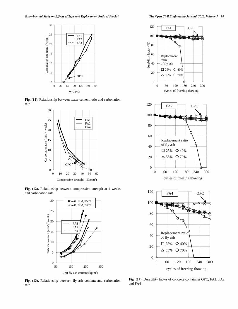
Fig. (11) shows the relationship between water cement ratio and carbonation rate. Relation between water cement ratio and carbonation rate is found to be the same of that of OPC concrete and concrete containing FA2 and FA4, while concrete containing FA1 shows slightly higher carbonation rate than the others with the same water binder ratio. Car-bonation rate can be considered roughly proportional to wa-ter binder ratio regardless of particle size and replacement ratio of fly ash, and the same result was provided as Meyer, A. [5] and Wada et al. [6].
0
10
20
30
40
50
60
Com
pres
sive
stre
ngth
(N
/mm
2 )
Specific surface area of fly ash (cm2/g)
W/(C+FA)=50%
1970 3760 5070
Replacement ratio of fly
FA4 FA1 FA2
0
10
20
30
40
50
60
0 1 2 3
Com
pres
sive
stre
ngth
(N/m
m2 )
(C+FA)/W
FA 2
13
OPC
25%
40%
55%
70%
Replacement ratio
0
10
20
30
40
50
60
0 1 2 3
Com
pres
sive
str
engt
h (N
/mm
2 )
C/W
13
OP
FA1 FA2 FA4
98 The Open Civil Engineering Journal, 2013, Volume 7 Quan and Kasami
Fig. (7). Effect of specific surface area of fly ash on drying shrink-age at 13 weeks.
Fig. (8). Carbonation depth by accelerating carbonation(W/(C+FA) =50%, at 5% CO2 ).
Fig. (9). Effect of specific surface area and replacement ratio of fly ash on carbonation rate.
Fig. (10). Relationship between water binder ratio and carbonation rate.
Fig. (12) shows the relationship between compressive strength at 4 weeks and carbonation rate. Carbonation rate of concrete with and without fly ashes in it decreases exponen-tially with the increase of compressive strength. Fly ash con-crete shows greater carbonation rate than OPC concrete with the same compressive strength. The increase in carbonation rate of fly ash concrete is caused by higher specific surface area of fly ash.
Fig. (13) shows the relationship between fly ash content and carbonation rate. Carbonation rate increases exponen-tially with the increase of fly ash content. The increase in carbonation rate of fly ash concrete can attribute to hysteretic formation of Ca(OH)2 caused by the fewer cement content and the decrease in Ca(OH)2 caused by the consumption in the pozzolanic reaction with fly ash. Higher carbonation rate of concrete with FA1 in it also can be explained by the higher pozzolanicity of FA1 with finer particle size and higher strength activity, as Masuda, Y. & et.al. discussed [7].
6.4. Resistance of Freezing and Thawing
Fig. (14) shows the durability factor of air-entrained con-crete containing OPC, FA1, FA2 and FA4 after 300 cycles of freezing and thawing. Durability factors of concrete with FA1 and FA2 replacing cement by 25% to 55% are higher than 80% of that of OPC concrete, while that of concrete with FA4 is less than 80% after 300 cycles. Concrete with FA replacing 70% cement is not durable and severely dam-aged by less than 300 cycles regardless of the type of fly ash or specific surface area.
7. CONCLUSIONS
Following conclusions are drawn from the experimental study on influences of type and replacement ratio of fly ash on strength and durability of concrete.
(1) Compressive strength increases with the increase in spe-cific surface area of fly ash, strength development be-comes slower with the increase of replacement ratio of fly ash.
0
100
200
300
400
500
600
700
800
Dry
ign
shrin
kage
(×10
-6)
Specific surface area of fly ash (cm2/g)
1970 3760
W/(C+FA)=50%
FA4 FA2 FA1
Replacement ratio of fly
□ 25% ◇ 40% △ 55% ○ 70%
0
10
20
30
40
50
60
Car
bona
tion
dept
h (m
m)
Term of carbonation (weeks)
OPC
25%
40%
55%
70%
1 4 8 13 26
Replacement ratio of fly ash
0
5
10
15
20
25
30
Car
bona
tion
rate
(m
m/√
wee
k)
Specific surface area of fly ash (cm2/g)
25%
1970 3760 5070
70%
55%
40%
Replacement ratio of fly
FA4 FA2 FA1
0
5
10
15
20
25
30
Car
bona
tion
rate
(mm
/√w
eek)
W/(C+FA) (%) 38 43 50 60
OPC
25 % 40
55
70 %
FA 2 Replacement ratio of fly ash
Experimental Study on Effects of Type and Replacement Ratio of Fly Ash The Open Civil Engineering Journal, 2013, Volume 7 99
Fig. (11). Relationship between water cement ratio and carbonation rate
Fig. (12). Relationship between compressive strength at 4 weeks and carbonation rate
Fig. (13). Relationship between fly ash contentt and carbonation rate
Fig. (14). Durability factor of concrete containing OPC, FA1, FA2 and FA4
0
5
10
15
20
25
30
0 30 60 90 120 150 180
Car
bona
tion
rate
(m
m/√
wee
k)
W/C (%)
OPC
FA1 FA2 FA4
0
5
10
15
20
25
30
0 10 20 30 40 50 60
Car
bona
tion
rate
(m
m/√
wee
k)
Compressive strenght (N/mm2)
OPC
FA1 FA2 FA4
0
5
10
15
20
25
30
50 150 250 350
Car
bona
tion
rate
(m
m/√
wee
k)
Unit fly ash content (kg/m3)
FA1 FA2 FA4
◆W/(C+FA)=50% ◇W/(C+FA)=43%
0
20
40
60
80
100
120
0 60 120 180 240 300
dura
bilit
y fa
ctor
(%)
cycles of freezing thawing
FA1 OPC
Replacement ratio of fly ash
□ 25% ◇ 40%
△ 55% ○ 70%
0
20
40
60
80
100
120
0 60 120 180 240 300
cycles of freezing thawing
FA2 OPC
Replacement ratio of fly ash
□ 25% ◇ 40%
△ 55% ○ 70%
0
20
40
60
80
100
120
0 60 120 180 240 300
cycles of freezing thawing
FA4 OPC
Replacement ratio of fly ash
□ 25% ◇ 40%
△ 55% ○ 70%
100 The Open Civil Engineering Journal, 2013, Volume 7 Quan and Kasami
(2) Drying shrinkage of concrete with FA1 and FA2 is smaller than OPC concrete and concrete with FA4, and a higher replacement ratio of fly ash lead to lower drying shrinkage.
(3) Concrete containing fly ash is more prone to be carbon-ated. A higher replacement ratio or higher content of fly ash in concrete leads to a higher carbonation rate. The in-crease in carbonation rate with the fly ash replacement may be attribute to the reduction of Ca(OH)2 formation caused by reduction of Portland cement and consumption of Ca(OH)2 in pozzolanic reaction of fly ash.
(4) Air-entraining concrete containing FA1 and FA2 fly ash replacing cement from 25% to 55% has better freezing and thawing resistance. Concrete with Fly ash replacing 70% cement is much less durable.
CONFLICT OF INTEREST
The author(s) confirm that this article content has no con-flicts of interest.
ACKNOWLEDGEMENTS
This research is supported by the Basic Research Projects of Qingdao Municipal Science and Technology Plan (No. 10-3-4-5-1-jch).
REFERENCES
[1] H Quan, “The Effects of Change in Fineness of Fly Ash on Air-entraining Concrete”, The Open Civil Engineering Journal, vol. 5, pp. 124-131, 2011
[2] S. Honda, and Shiiba, “Several properties of concrete using high-volume fly ash”, In: Proceedings of the Japan Concrete Institute, vol. 23, no. 2, pp.127-132, 2001 (in Japanese)
[3] A, Neville, “Properties of concrete Longman Scientific & Techni-cal Harlow, Essex UK, 3rd ed. Wiley: NY, 1981, pp.391-395.
[4] M, Hamada. “Carbonation of Concrete and Corrosion of Reinforc-ing Steel”, In: Proceedings of the Cement Association of Japan, Cement & Concrete, no.272, pp.2-18, Oct. 1969
[5] A, Meyer. “Investigation on the carbonation of concrete”, In: Pro-ceedings of 5th Int.Symp. on Chemistry of Cement, Part 3, pp.394-401, 1968
[6] S, Wada. Abe, M., Yanagi, K. & Fujita, K. “Experimental Study on Carbonation”, Watertightness and Salt Interruption of Fly Ash Concrete, Proceedings of the Japan Concrete Institute, vol.20, no.2, 1998, pp.121-126. (in Japanese)
[7] Y, Masuda. & Tanano, H., “Prediction model for progress of con-crete carbonation”, In: Proceedings of Durability of Building Mate-rial and Components, pp.1152-1161, 1993.
Received: November 09, 2012 Revised: November 09, 2012 Accepted: January 03, 2013
© Quan and Kasami; Licensee Bentham Open. This is an open access article licensed under the terms of the Creative Commons Attribution Non-Commercial License (http://creativecommons.org/licenses/ by-nc/3.0/) which permits unrestricted, non-commercial use, distribution and reproduction in any medium, provided the work is properly cited.