Embed Size (px)
Citation preview
Exploring the
Boundaries of
Porphyrin Materials
Synthesis by Ionic
Self-Assembly
João Pedro Gomes dos Santos
Mestrado em Bioquímica
Química e Bioquímica
2015
Orientador
Craig Medforth, Principal Investigator, UCIBIO@REQUIMTE
Departamento de Química e Bioquímica
Faculdade de Ciências, Universidade do Porto

2 FCUP Exploring the Boundaries of Porphyrin Materials Synthesis by Ionic Self-Assembly

FCUP Exploring the Boundaries of Porphyrin Materials Synthesis by Ionic Self-Assembly
i

ii FCUP Exploring the Boundaries of Porphyrin Materials Synthesis by Ionic Self-Assembly

FCUP Exploring the Boundaries of Porphyrin Materials Synthesis by Ionic Self-Assembly
iii
Acknowledgments
Many people contributed to the success of my Master’s degree and this section is
dedicated to them.
To my family for all the support and teachings in all these years
To my girlfriend and friends for making this journey much easier and pleasant.
To Craig for accepting me into this project and for his help and teaching throughout.
To Pedro and Miguel for their help in the lab.
To Filipa and Beatriz for letting me be a teacher for the first time.

iv FCUP Exploring the Boundaries of Porphyrin Materials Synthesis by Ionic Self-Assembly

FCUP Exploring the Boundaries of Porphyrin Materials Synthesis by Ionic Self-Assembly
v
Resumo
As porfirinas são componentes atrativos para serem usados em fotónica, catálise,
células solares e fotossíntese artificial devido as suas características catalíticas,
eletrónicas e óticas. Como resultado a síntese e possíveis aplicações de nanomateriais
de porfirinas emergiram como uma área de interesse científico nos últimos anos. Vários
métodos, tais como reprecipitação e polimerização de coordenação têm sido usados
para produzir nanomateriais constituídos por um único tipo de porfirina e a auto
montagem iónica (Ionic Self-assembly, ISA) de porfirinas com cargas opostas tem sido
usado para preparar nanomateriais catalíticos de dois tipos de porfirinas diferentes.
Neste trabalho é explorada em solução aquosa e a pH 2 a auto montagem iónica de
uma nova grande porfirina octocatiónica (LOCP) com a tetra(4-sulfonatofenil)-porfirina
(TPPS).
As reações entre as formas metálicas da TPPS (MTPPS) e a LOCP produzem materiais
que são consistentes com ISA apesar de mostrarem características estranhas não
anteriormente notadas para ISA de porfirinas.
As imagens de microscopia de transmissão eletrónica (TEM) e microscopia eletrónica
de varrimento mostram nanopartículas e placas com micrómetros de tamanho.
As reações entre a H4TPPS e a LOCP também produzem precipitados com
nanopartículas e “bolachas” com mícrones de tamanho, apesar de as reações não
demonstrarem um comportamento de ISA.
As reações entre a LOCP e dois tipos diferentes de MTPPS são também produzidas,
numa tentativa bem-sucedida de formar nanomateriais ternários de porfirina usando a
alta carga da LOCP
Palavras-chave: Porfirina, ISA, nanopartícula, LOCP, TPPS

vi FCUP Exploring the Boundaries of Porphyrin Materials Synthesis by Ionic Self-Assembly

FCUP Exploring the Boundaries of Porphyrin Materials Synthesis by Ionic Self-Assembly
vii
Abstract
Porphyrins are attractive components to be used in photonics, catalysis, solar cells and
artificial photosynthesis due to their catalytic, electronic and optical properties. As a result
the synthesis and possible applications of porphyrins nanomaterials have emerged as
an area of research interest in recent years. Various methods, such as reprecipitation
and coordination polymerization have been used to produce nanomaterials containing a
single porphyrin type and Ionic Self Assembly (ISA) of oppositely charged porphyrins
has been used to prepare catalytic binary porphyrin nanomaterials.
In this Master thesis, the ISA reactions of a novel Large Octacationic Porphyrin (LOCP)
with tetra (4-sulfonatophenyl)-porphyrin (TPPS) are explored in aqueous solutions at pH
2.
Reactions between Metal TPPS (MTPPS) and LOCP produce materials that are
consistent with ISA but display some unusual features not previously noted for porphyrin
ISA. Transmission Electron Microscopy (TEM) and Scanning Electron Microscopy (SEM)
images show nanoparticles and micro-sized wafers.
Reactions between H4TPPS and LOCP also produce precipitates with nanoparticles and
micro-sized wafers, although the reactions do not display ISA behaviour.
Reactions between LOCP and two different MTPPS are also performed in a successful
attempt to form ternary porphyrin nanomaterials using the high charge of LOCP.
Key words: Porphyrin, ISA, nanoparticle, LOCP, TPPS
viii FCUP Exploring the Boundaries of Porphyrin Materials Synthesis by Ionic Self-Assembly
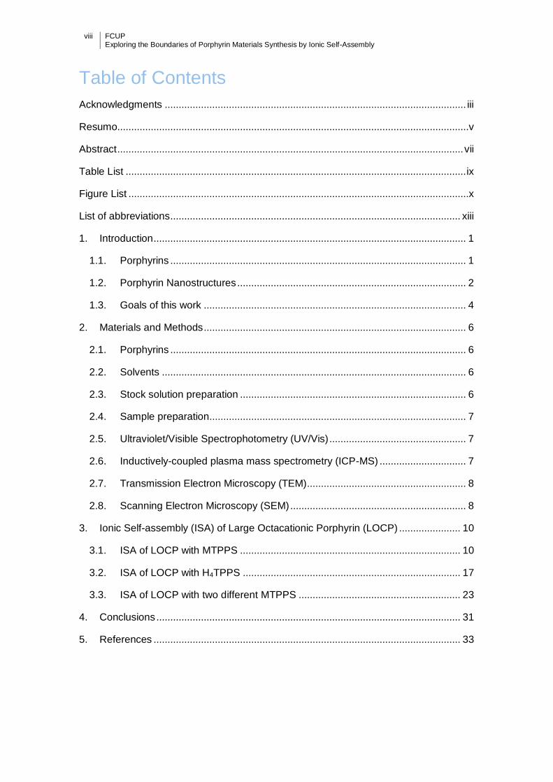
Table of Contents
Acknowledgments ............................................................................................................ iii
Resumo..............................................................................................................................v
Abstract ............................................................................................................................ vii
Table List .......................................................................................................................... ix
Figure List ..........................................................................................................................x
List of abbreviations ........................................................................................................ xiii
1. Introduction ................................................................................................................ 1
1.1. Porphyrins .......................................................................................................... 1
1.2. Porphyrin Nanostructures .................................................................................. 2
1.3. Goals of this work .............................................................................................. 4
2. Materials and Methods .............................................................................................. 6
2.1. Porphyrins .......................................................................................................... 6
2.2. Solvents ............................................................................................................. 6
2.3. Stock solution preparation ................................................................................. 6
2.4. Sample preparation............................................................................................ 7
2.5. Ultraviolet/Visible Spectrophotometry (UV/Vis) ................................................. 7
2.6. Inductively-coupled plasma mass spectrometry (ICP-MS) ............................... 7
2.7. Transmission Electron Microscopy (TEM)......................................................... 8
2.8. Scanning Electron Microscopy (SEM) ............................................................... 8
3. Ionic Self-assembly (ISA) of Large Octacationic Porphyrin (LOCP) ...................... 10
3.1. ISA of LOCP with MTPPS ............................................................................... 10
3.2. ISA of LOCP with H4TPPS .............................................................................. 17
3.3. ISA of LOCP with two different MTPPS .......................................................... 23
4. Conclusions ............................................................................................................. 31
5. References .............................................................................................................. 33
FCUP Exploring the Boundaries of Porphyrin Materials Synthesis by Ionic Self-Assembly
ix
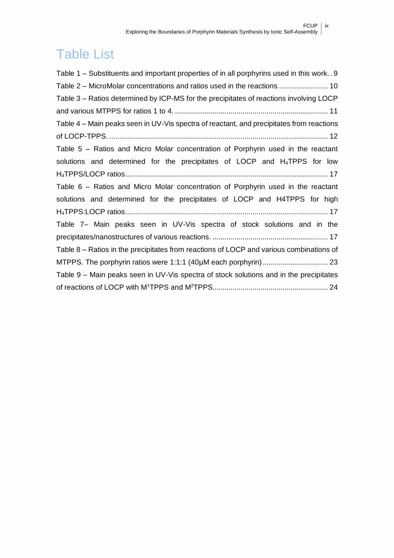
Table List
Table 1 – Substituents and important properties of in all porphyrins used in this work. . 9
Table 2 – MicroMolar concentrations and ratios used in the reactions. ........................ 10
Table 3 – Ratios determined by ICP-MS for the precipitates of reactions involving LOCP
and various MTPPS for ratios 1 to 4. ............................................................................. 11
Table 4 – Main peaks seen in UV-Vis spectra of reactant, and precipitates from reactions
of LOCP-TPPS. .............................................................................................................. 12
Table 5 – Ratios and Micro Molar concentration of Porphyrin used in the reactant
solutions and determined for the precipitates of LOCP and H4TPPS for low
H4TPPS/LOCP ratios ...................................................................................................... 17
Table 6 – Ratios and Micro Molar concentration of Porphyrin used in the reactant
solutions and determined for the precipitates of LOCP and H4TPPS for high
H4TPPS:LOCP ratios ...................................................................................................... 17
Table 7– Main peaks seen in UV-Vis spectra of stock solutions and in the
precipitates/nanostructures of various reactions. .......................................................... 17
Table 8 – Ratios in the precipitates from reactions of LOCP and various combinations of
MTPPS. The porphyrin ratios were 1:1:1 (40µM each porphyrin) ................................. 23
Table 9 – Main peaks seen in UV-Vis spectra of stock solutions and in the precipitates
of reactions of LOCP with M1TPPS and M2TPPS. ......................................................... 24

x FCUP Exploring the Boundaries of Porphyrin Materials Synthesis by Ionic Self-Assembly
Figure List
Figure 1 – Structural formula of Porphine ........................................................................ 1
Figure 2 – From left to right structural formulas of Porphine, Porphodimethane,
Porphyrinogen, ChIorin, Bacteriochlorin, lsobacteriochlorin ............................................ 1
Figure 3 – Crystal structure of LOCP. Adapted from Jiang, L. et al. ............................... 4
Figure 4 – Structural formula of LOCP ............................................................................. 4
Figure 5 – Structural formula of H4TPPS ......................................................................... 5
Figure 6 – From left to right, representations of: Side and top view of a monomer of
H4TPPS2-, side and top view of a J-aggregate................................................................. 5
Figure 7 – Structural formula of the Porphyrin that serves as a base for the porphyrins in
this work ............................................................................................................................ 6
Figure 8 – Unprotonated (left) and protonated (right) form of LOCP ............................ 10
Figure 9 – UV-Vis spectra obtained in the reaction of LOCP with SnIVTPPS in a ratio of
1:1 and 2:1 and the SnIVTPPS porphyrin. ...................................................................... 13
Figure 10 – UV-Vis spectra of the nanostructure obtained for the reaction of LOCP with
CuIITPPS in a ratio of 2:1 and the two starting porphyrins. ........................................... 13
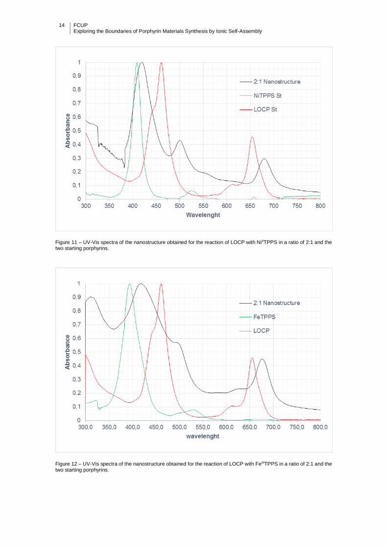
Figure 11 – UV-Vis spectra of the nanostructure obtained for the reaction of LOCP with
NiIITPPS in a ratio of 2:1 and the two starting porphyrins. ............................................ 14
Figure 12 – UV-Vis spectra of the nanostructure obtained for the reaction of LOCP with
FeIIITPPS in a ratio of 2:1 and the two starting porphyrins. ........................................... 14
Figure 13 – UV-Vis spectra of the nanostructure obtained for the reaction of LOCP with
SnIVTPPS in a ratio of 2:1 and the two starting porphyrins............................................ 15
Figure 14 – UV-Vis spectra of the nanostructure obtained for the reaction of LOCP with
MnIVTPPS in a ratio of 2:1 and the two starting porphyrins. .......................................... 15
Figure 15 – TEM (a,b) and optical microscopy (c) images of LOCP + MTPPS
nanostructures. In the SEM image each grid has a side of 100 µm.............................. 16
Figure 16 – UV-Vis spectra of the nanostructure obtained in the reaction of LOCP with
H4TPPS in a ratio of 4:1 and the two starting porphyrins. ............................................. 18
Figure 17 – UV-Vis spectra of the nanostructure obtained in the reaction of LOCP with
H4TPPS in ratios1 to 4. .................................................................................................. 19
Figure 18 – Representation of two hypothetical different aggregation conformations for
a reaction between H4TPPS (small diamond shape) and LOCP (large octahedrons) in a
2:1 ratio producing J-aggregates (right) or not (left). ..................................................... 19
Figure 19 – Representation of three hypothetical different aggregation conformations for
a reaction between H4TPPS (small diamond shape) and LOCP (large octahedrons) in a
4:1 ratio producing J-aggregates (middle and right) or not (left). .................................. 20

FCUP Exploring the Boundaries of Porphyrin Materials Synthesis by Ionic Self-Assembly
xi
Figure 20 – Representation of two hypothetical different aggregation conformations for
a reaction between H4TPPS (small diamond shaped) and LOCP (large octahedrons) in
a 16:1 ratio (left) and demonstrating the nanostructures in equilibrium with free porphyrin
(right). .............................................................................................................................. 20
Figure 21 – UV-Vis spectra of the nanostructure obtained in the reaction of LOCP with
H4TPPS in ratios 4 to 8. ................................................................................................. 21
Figure 22 – Plot showing the various H4TPPS: Porphyrin1 ratios expected and the one
obtained .......................................................................................................................... 21
Figure 23 – TEM(a) and SEM(b) images of LOCP and H4TPPS nanostructures ........ 22
Figure 24 – UV-Vis spectra of the nanostructure obtained in the reaction of LOCP with
CuTPPS and NiTPPS (1:1:1 ratio) compared with the UV-Vis spectra of the
nanostructures of the reactions of LOCP with CuTPPS (1:2 ratio) or NiTPPS (1:2 ratio).
........................................................................................................................................ 25
Figure 25 – UV-Vis spectra of the nanostructure obtained in the reaction of LOCP with
CuTPPS and FeTPPS (1:1:1 ratio) compared with the UV-Vis spectra of the
nanostructures of the reactions of LOCP with CuTPPS (1:2 ratio) or FeTPPS (1:2 ratio).
........................................................................................................................................ 25
Figure 26 – UV-Vis spectra of the nanostructure obtained in the reaction of LOCP with
CuTPPS and SnTPPS (1:1:1 ratio) compared with the UV-Vis spectra of the
nanostructures of the reactions of LOCP with CuTPPS (1:2 ratio) or SnTPPS (1:2 ratio).
........................................................................................................................................ 26
Figure 27 – UV-Vis spectra of the nanostructure obtained in the reaction of LOCP with
CuTPPS and MnTPPS (1:1:1 ratio) compared with the UV-Vis spectra of the
nanostructures of the reactions of LOCP with CuTPPS (1:2 ratio) or MnTPPS (1:2 ratio).
........................................................................................................................................ 26
Figure 28 – UV-Vis spectra of the nanostructure obtained in the reaction of LOCP with
NiTPPS and FeTPPS (1:1:1 ratio) compared with the UV-Vis spectra of the
nanostructures of the reactions of LOCP with NiTPPS (1:2 ratio) or FeTPPS (1:2 ratio).
........................................................................................................................................ 27
Figure 29 – UV-Vis spectra of the nanostructure obtained in the reaction of LOCP with
NiTPPS and SnTPPS (1:1:1 ratio) compared with the UV-Vis spectra of the
nanostructures of the reactions of LOCP with NiTPPS (1:2 ratio) or SnTPPS (1:2 ratio).
Note: Reaction done at pH 1 and this results in the extra Soret band at 439 nm. ........ 27
Figure 30 – UV-Vis spectra of the nanostructure obtained in the reaction of LOCP with
NiTPPS and MnTPPS (1:1:1 ratio) compared with the UV-Vis spectra of the
nanostructures of the reactions of LOCP with NiTPPS (1:2 ratio) or MnTPPS (1:2 ratio).
........................................................................................................................................ 28
xii FCUP Exploring the Boundaries of Porphyrin Materials Synthesis by Ionic Self-Assembly
Figure 31 – UV-Vis spectra of the nanostructure obtained in the reaction of LOCP with
FeTPPS and SnTPPS (1:1:1 ratio) compared with the UV-Vis spectra of the
nanostructures of the reactions of LOCP with FeTPPS (1:2 ratio) or SnTPPS (1:2 ratio).
........................................................................................................................................ 28
Figure 32 – UV-Vis spectra of the nanostructure obtained in the reaction of LOCP with
FeTPPS and MnTPPS (1:1:1 ratio) compared with the UV-Vis spectra of the
nanostructures of the reactions of LOCP with FeTPPS (1:2 ratio) or MnTPPS (1:2 ratio).
........................................................................................................................................ 29
Figure 33 – UV-Vis spectra of the nanostructure obtained in the reaction of LOCP with
SnTPPS and MnTPPS (1:1:1 ratio) compared with the UV-Vis spectra of the
nanostructures of the reactions of LOCP with SnTPPS (1:2 ratio) or MnTPPS (1:2 ratio).
........................................................................................................................................ 29
Figure 34 – TEM images of LOCP, CuIITPPS and FeIIITPPS nanostructures at two
different magnifications. ................................................................................................. 30
Figure 35 – Structural formula of Br8TPPS .................................................................... 32
Figure 36 – Structural formula of Br8TMPyP .................................................................. 32

FCUP Exploring the Boundaries of Porphyrin Materials Synthesis by Ionic Self-Assembly
xiii
List of abbreviations
BIPNs Binary Ionic Porphyrin Nanomaterials
CBI Cooperative Binary Ionic
ICP-MS Inductively-coupled plasma mass spectrometry
ISA Ionic Self-Assembly
ITAPs Ionic tetraarylporphyrins
LED Light emitting diode
UV/Vis Ultraviolet/Visible Spectrophotometry
TEM Transmission Electron Microscopy
SEM Scanning Electron Microscopy
Br8TMPyP 2,3,7,8,12,13,17,18-octabromotetra(N-methyl-4-pyridyl)porphyrin
Br8TPPS 2,3,7,8,12,13,17,18-octabromotetra(4-sulfonatophenyl)porphyrin
CuIITPPS Copper (II) tetra(4-sulfonatophenyl)-porphyrin
FeIIITPPS Iron (III) tetra(4-sulfonatophenyl)-porphyrin
H4TPPS Tetra(4-sulfonatophenyl)-porphyrin dication
LOCP Large Octacationic Porphyrin
MnIIITPPS Manganese (III) tetra(4-sulfonatophenyl)-porphyrin
MTPPS Metal tetra(4-sulfonatophenyl)-porphyrin
NiIITPPS Nickel (II) tetra(4-sulfonatophenyl)-porphyrin
SbVO-TPP Oxo-antimony(V) tetraphenylporphyrin
SnIVTPPS Tin (IV) tetra(4-sulfonatophenyl)-porphyrin
SnIVTPyP Tin (IV) tetra(4-pyridyl)porphyrin
SnIVTMPyP Tin (IV) tetra(N-methyl-4-pyridyl)porphyrin
TEtOHPyP Tetra(2-hydroxyethyl-4-Pyridyl)porphyrin
TMPyP Meso-tetra(N-methyl-4-pyridyl)porphyrin
TPPS Tetra(4-sulfonatophenyl)-porphyrin
ZnIITPPS Zinc (II) tetra(4-sulfonatophenyl)-porphyrin

FCUP Exploring the Boundaries of Porphyrin Materials Synthesis by Ionic Self-Assembly
1
1. Introduction
1.1. Porphyrins
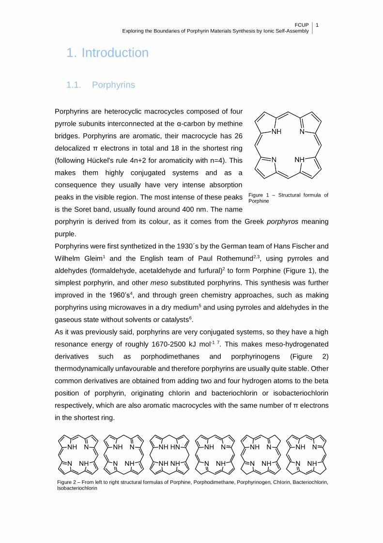
Porphyrins are heterocyclic macrocycles composed of four
pyrrole subunits interconnected at the α-carbon by methine
bridges. Porphyrins are aromatic, their macrocycle has 26
delocalized π electrons in total and 18 in the shortest ring
(following Hückel's rule 4n+2 for aromaticity with n=4). This
makes them highly conjugated systems and as a
consequence they usually have very intense absorption
peaks in the visible region. The most intense of these peaks
is the Soret band, usually found around 400 nm. The name
porphyrin is derived from its colour, as it comes from the Greek porphyros meaning
purple.
Porphyrins were first synthetized in the 1930´s by the German team of Hans Fischer and
Wilhelm Gleim1 and the English team of Paul Rothemund2,3, using pyrroles and
aldehydes (formaldehyde, acetaldehyde and furfural)2 to form Porphine (Figure 1), the
simplest porphyrin, and other meso substituted porphyrins. This synthesis was further
improved in the 1960’s4, and through green chemistry approaches, such as making
porphyrins using microwaves in a dry medium5 and using pyrroles and aldehydes in the
gaseous state without solvents or catalysts6.
As it was previously said, porphyrins are very conjugated systems, so they have a high
resonance energy of roughly 1670-2500 kJ mol-1 7. This makes meso-hydrogenated
derivatives such as porphodimethanes and porphyrinogens (Figure 2)
thermodynamically unfavourable and therefore porphyrins are usually quite stable. Other
common derivatives are obtained from adding two and four hydrogen atoms to the beta
position of porphyrin, originating chIorin and bacteriochlorin or isobacteriochlorin
respectively, which are also aromatic macrocycles with the same number of π electrons
in the shortest ring.
Figure 2 – From left to right structural formulas of Porphine, Porphodimethane, Porphyrinogen, ChIorin, Bacteriochlorin, lsobacteriochlorin
Np
Figure 1 – Structural formula of Porphine

2 FCUP Exploring the Boundaries of Porphyrin Materials Synthesis by Ionic Self-Assembly
1.1.1. Biological importance
In biological systems, porphyrins and related tetrapyrroles such as chlorophylls are very
important when incorporated into proteins. There, they play a central role in many
essential processes. Maybe their most important role is in the energy reactions of
advanced life, namely photosynthesis and respiration. In photosynthesis, Chlorophylls
and porphyrins are responsible for the capture of photons and the transfer of electrons,
essential to the production of energy for almost all life on earth8,9. In contrast, the
porphyrin heme contained in Cytochrome C oxidase and other enzymes are responsible
for energy production during cellular respiration10.
Porphyrins also perform other catalytic roles such as catalysis in nitric oxide synthase,
catalase, and oxygen transport and storage in the haemoglobin and myoglobin proteins.
In fact, it’s the porphyrin in haemoglobin that gives blood its red colour10.
1.1.2. Applications
Apart from their role in biological systems, porphyrins have also been used in various
technological and medical applications. In medicine, vertporphyn has been used to treat
eye macular degeneration by phototherapy11, and the presence of abnormal amounts of
porphyrins constitutes a disease called porphyria12, famous for its incidence in European
aristocracy. In the technology area, porphyrins have been used to try and simulate
photosynthesis11,12, in dye-sensitized solar cells13-15, in LEDs16, in photonic devices17 (for
information transfer with light) and optoelectronics18, as catalysts and photocatalysts for
the fixation and trans-formation of carbon dioxide19, and as potential tools for
delignification20 for the wood industry.
1.2. Porphyrin Nanostructures
There are various ways to make porphyrins self-assemble into nanostructures. Three of
the most used procedures are the reprecipitation method, coordination polymerization
and ionic self-assembly (ISA). In the reprecipitation method, one porphyrin species
dissolved in a solvent where it is soluble is quickly mixed into a much greater quantity of
solvent where it is insoluble leading to its precipitation. This method is probably the
simplest of the three and the most commonly used to produce nanostructures of a single
type of porphyrin21-24. In the coordination polymerization method, metals are used to
make the linking bridge between different porphyrins. There are 2 types, type A in which
the metal is contained in the porphyrin and where the links are between it and ligating

FCUP Exploring the Boundaries of Porphyrin Materials Synthesis by Ionic Self-Assembly
3
peripheral substituents of the same kind of porphyrin25, and type B were an external
metal is added to solution and serves as a link between the ligating peripheral
substituents of the porphyrin26. In ISA the soluble porphyrin ion is neutralized by an
oppositely charged porphyrin or ion. This neutralization makes the system insoluble,
leading to the formation of crystalline or amorphous solids27-30. The resulting binary
organic solids can combine different porphyrin properties and are of increased interest.
In classical ISA reactions, the main interactions that lead to aggregation are coloumbic
interactions and the fitting of the diverse secondary structure of the elements involved,
which leads to the solids being made of only the starting material in ratios only defined
by their charge30.
The ISA method is used in this work and, therefore, some structures prepared to date
with porphyrins using this technique should be enumerated to serve as a framework for
this work.
Porphyrins nanotubes/nanorods
The first porphyrin nanostructures produced by ISA, reported in 2004 by Wang et
al.31 and further investigated by others32. The ones produced by the Wang team
used H4TPPS2- and SnIVTPyP4+/5+.
Porphyrin nanofibers and nanofiber bundles
Reported in 2006 by Wang et al33, using H2TPPS4- and SbVOTPP5+.
Porphyrin four-leaf clover-like dendritic structures
Reported in 2010 by Martin et al.34 the structures are formed by various metal
combinations of TEtOHPyP4+ and TPPS4−,and resemble four leaf clovers or four
sided ninja stars that can be slightly modulated in shape by changing the metals
or altering the temperature in the reactions.
Nanosheets: First X-ray structure of a CBI solid
Made with ZnTPPS4- porphyrins and with SnTMPyP4+ a system very similar to
the one used to obtain the previous structures being the only difference a methyl
group instead of an ethyl in the Sn porphyrin. Some of this nanosheets where so
large that there was obtained a crystal large enough for X-ray crystallography,
that was the first for Cooperative Binary Ionic (CBI) solids35.
Two interesting techniques used to increase the complexity and potential uses of solids
obtained by ISA are the variation of the pH of the reaction medium, that makes it possible
to obtain various compositions and structures from the same material, or the growing of
structures on top of other structures (this works by mixing two different porphyrins,
allowing them form a structure, and then adding a solution that contains two new
porphyrins that react on top of it).

4 FCUP Exploring the Boundaries of Porphyrin Materials Synthesis by Ionic Self-Assembly
1.3. Goals of this work
Binary Ionic Porphyrin Nanomaterials
produced by ISA are relatively new. To
date studies have mainly focused on
readily available ionic tetraarylporphyrins
(ITAPs) such as TMPyP4+ and TPPS4- 36.
Therefore very little is known about ISA
reactions of Porphyrin tectons with novel
and unusual structures and properties. In
this work the limits of porphyrin ISA are
studied by trying to use an unusual Large
Octacationic Porphyrin (LOCP) (Figure 3
and Figure 4)37.
LOCP has an extended π-system of the
tetrabenzoporphyrin class, with each
benzene substituent having two extra aryl
substituents. In addition, there are also
Aryl substituents at the meso position that
contribute to a significant steric crowding
of the periphery of the porphyrin. This is
relieved by deformation of the ring into a
non-planar conformation, making the
shape of LOCP similar to a horse saddle as depicted in Figure 3. Both of these
characteristics, extension of the π-system and non-planarity might be useful for
designing a material with specific light absorption features or specific oxidation or
reduction potentials. Additionally, LOCP also has an unusually high charge when all its
substituents are protonated (8+ at pH 2, the pKa of pyridine is 5,2538) compared to
previously investigated ITAPs36.
The work with LOCP was started with no knowledge of its capacity to form any kind of
nanostructure. It could very well be that the unusual characteristics of this porphyrin
could contribute to increased stability in water, or in the solid state, either disfavouring or
favouring the formation of ionic solids precipitates. To try to increase the odds of
precipitate formation, reactions were prepared with the metal and metal-free forms of the
aforementioned well studied porphyrins (TPPS4-) (Figure 5), which have been used to
prepare several other porphyrin ionic solid complexes.
Figure 3 – Crystal structure of LOCP. Adapted from Jiang, L. et al.
Figure 4 – Structural formula of LOCP

FCUP Exploring the Boundaries of Porphyrin Materials Synthesis by Ionic Self-Assembly
5
The reactions with Metal complexes of
TPPS are discussed in Section 3.1. The
metals used were CuII, NiII FeIII, SnIV, MnIII
and the reactions were carried out at pH 2
to guarantee that LOCP is fully
protonated. In these reactions the Metal
TPPSs (MTPPSs) should be present as
tetraanaions (due to the toluene sulfonic
acid having a pKa of -2.8)39 (effective
charge 4-) with mostly planar macrocycles.
The reactions with H4TPPS (Figure 5)
gave very different results from the ones
with MTPPSs so they are discussed
separately in section 3.2. In these reactions, the TPPS complexes should also be a
tetraanion but because it is diprotonated in the core, due to the reaction being carried
out at pH 2 (pK3 4.99, pK4 4.7640) the charge will be 2-. Contrary to MTPPSs, this gives
rise to a very nonplanar structure for H4TPPS2- due to the steric crowding of protons in
the core of the porphyrin,41 making this reaction also exceptional as a rare example of
ionic self-assembly between two very nonplanar porphyrin tectons.
The different results obtained with H4TPPS2- are likely due to the tendency that this
porphyrin has to self-aggregate and form what are called J-aggregates at high ionic
strengths.42-44 This tendency arises from the fact that, at low pH values, this porphyrin
has four negative charges on the outside and two positive charges on the inside. This
characteristic makes it easy to form structures as the ones represented in Figure 6,
where the porphyrins stack diagonally on top of each other to form long nano-strands.
Figure 6 – From left to right, representations of: Side and top view of a monomer of H4TPPS2-, side and top view of a J-
aggregate
Figure 5 – Structural formula of H4TPPS
6 FCUP Exploring the Boundaries of Porphyrin Materials Synthesis by Ionic Self-Assembly
After gaining some understanding of the system with the two previous reactions, we tried
to take advantage of the high charge of LOCP to react it with two different MTPPSs at
the same time. If successful, this would give rise to Ternary Porphyrin Ionic Solids (the
first of their kind). This would be a very valuable addition to the portfolio of possible
different porphyrin solids, as it would be an easy way to bring close together up to three
different porphyrin for purposes such as light harvesting or catalysis.
2. Materials and Methods
2.1. Porphyrins
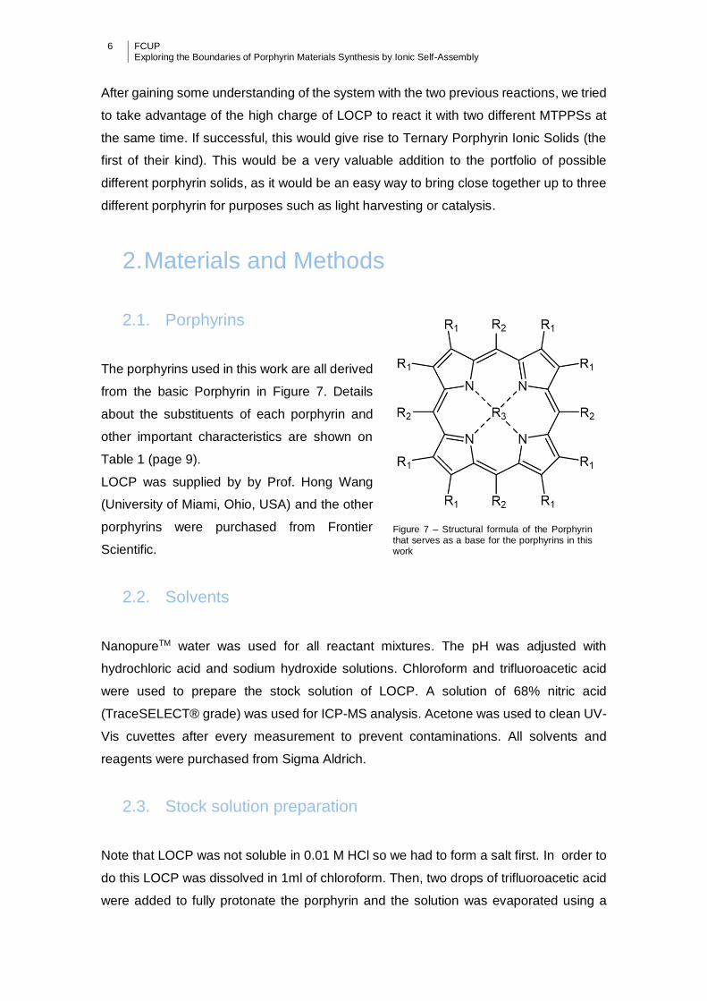
The porphyrins used in this work are all derived
from the basic Porphyrin in Figure 7. Details
about the substituents of each porphyrin and
other important characteristics are shown on
Table 1 (page 9).
LOCP was supplied by by Prof. Hong Wang
(University of Miami, Ohio, USA) and the other
porphyrins were purchased from Frontier
Scientific.
2.2. Solvents
NanopureTM water was used for all reactant mixtures. The pH was adjusted with
hydrochloric acid and sodium hydroxide solutions. Chloroform and trifluoroacetic acid
were used to prepare the stock solution of LOCP. A solution of 68% nitric acid
(TraceSELECT® grade) was used for ICP-MS analysis. Acetone was used to clean UV-
Vis cuvettes after every measurement to prevent contaminations. All solvents and
reagents were purchased from Sigma Aldrich.
2.3. Stock solution preparation
Note that LOCP was not soluble in 0.01 M HCl so we had to form a salt first. In order to
do this LOCP was dissolved in 1ml of chloroform. Then, two drops of trifluoroacetic acid
were added to fully protonate the porphyrin and the solution was evaporated using a
Figure 7 – Structural formula of the Porphyrin that serves as a base for the porphyrins in this work
FCUP Exploring the Boundaries of Porphyrin Materials Synthesis by Ionic Self-Assembly
7
rotary evaporator and vacuum dried overnight to remove the residual chloroform and
trifluoroacetic acid. It was then dissolved in 0.01M HCl for the experiment. All other
porphyrins were dissolved directly in 0.01M HCl. The stock solutions prepared had the
following concentrations: LOCP 100 µM, MTPPS 400 µM, H4TPPS 400 µM and 2 mM.
2.4. Sample preparation
Two or three different porphyrin solutions were combined in a glass vial (5 or 18 mL
capacity) using appropriate volumes to obtain the desired concentrations. The volume
was always adjusted to 2 mL and the solutions were left undisturbed and in the dark for
a week to allow the formation of precipitates. LOCP target concentration was always 40
µM except in the case of H4TPPS:LOCP high-ratio reactions where 16 µM were used to
avoid a need for stock solutions of excessively high concentration.
For example, to make the reaction solution of CuTPPS:LOCP (80:40), starting with stock
solutions 400 µM and 100 µM respectively, 0.8 mL of LOCP and 0.4 mL of CuTPPS were
mixed with 0.8 mL of 0.01 M HCl in a glass vial.
2.5. Ultraviolet/Visible Spectrophotometry (UV/Vis)
Samples were prepared by collecting 1 mL or 500 µL of the homogenised solution and
centrifuging it at 18000 g for 10 minutes in an Eppendorf microtube. The supernatant
was collected and placed in a different tube while the precipitate was re-suspended in
0.01m HCl. The supernatant and precipitate were then diluted with 0.01M HCl to allow
the analysis of the peaks of interest. UV-Vis spectra were obtained using a Shimadzu
UV-3600 Spectrophotometer. For this thesis all graphs were scaled to have a max
absorbance of 1 for better comparison between the bands.
2.6. Inductively-coupled plasma mass spectrometry (ICP-MS)
Samples were prepared by collecting 1 mL of homogenized reaction solution and
centrifuging at 18000 g for 10 minutes. The supernatant was discarded and the
precipitate was re-suspended in 1 mL of 68% nitric acid (TraceSELECT® grade). Then,
it was transferred to a Falcon tube and the volume adjusted to 5 mL by adding
NanopureTM water. Control samples were prepared by diluting 1 mL nitric acid to 5 mL
using NanopureTM water. ICP-MS samples were then taken to REQUIMTE Analysis
8 FCUP Exploring the Boundaries of Porphyrin Materials Synthesis by Ionic Self-Assembly
Laboratory in the Department of Chemistry at the Universidade Nova de Lisboa where
the analysis was performed.
2.7. Transmission Electron Microscopy (TEM)
Samples were prepared by collecting 1 mL of homogenized reaction solution and
centrifuging it at 18000 g for 10 minutes. The supernatant was discarded and the
precipitate was re-suspended in 1mL of 0.01 M HCl. Then, 10µL either from the re-
suspended precipitate or a 10X dilution (depending on the amount of precipitate), was
collected with a pipette and placed on a carbon-coated copper grid for TEM analysis.
This grid was left to dry at room temperature for one day. TEM was performed using a
HITACHI H-8100 microscope operated at 200 kV.
In some samples Energy-dispersive X-ray spectroscopy (EDX) was performed using a
ThermoNoran EDS scanner to try and determine the relative amounts of different metals
in the nanostructures.
2.8. Scanning Electron Microscopy (SEM)
Samples were prepared in a similar way to those of the TEM samples, using carbon
coated copper grids. The analysis was then performed using a FEI Quanta 400 FEG
scanning electron microscope (CEMUP, University of Porto) typically operated at 15 kV
and at 10 mm working distance. The SEM data shown are from secondary electron
images.

FCUP Exploring the Boundaries of Porphyrin Materials Synthesis by Ionic Self-Assembly
9
Table
1 –
Substitu
ents
and im
porta
nt p
ropertie
s o
f all p
orp
hyrin
s u
sed in
this
work
.
R
1 R
2 R
3 M
ole
cu
lar w
eig
ht
λ(ε×
10
-3) pH
2
Ch
arg
e a
t pH
2
LO
CP
Ni
16
56
.68
46
1 (1
18
,6)
8+
H4 T
PP
S
H
4H
9
30
.05
43
5 (4
09
.5)
2-
Cu
TP
PS
C
u
99
2.4
8
41
2 (2
74
.7)
4-
NiT
PP
S
Ni
98
7.6
3
40
9 (1
60
.5)
4-
Fe
TP
PS
F
e
98
4.7
2
39
4 (1
21
.6)
4-
Sn
TP
PS
S
n
10
47
.64
41
6 (5
33
.3)
4-
Mn
TP
PS
M
n
98
3.8
7
46
8 (7
7.8
) 4
-
10 FCUP Exploring the Boundaries of Porphyrin Materials Synthesis by Ionic Self-Assembly
3. Ionic Self-assembly (ISA) of Large
Octacationic Porphyrin (LOCP)
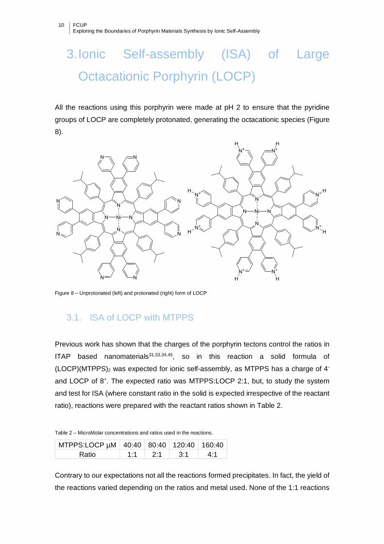
All the reactions using this porphyrin were made at pH 2 to ensure that the pyridine
groups of LOCP are completely protonated, generating the octacationic species (Figure
8).
Figure 8 – Unprotonated (left) and protonated (right) form of LOCP
3.1. ISA of LOCP with MTPPS
Previous work has shown that the charges of the porphyrin tectons control the ratios in
ITAP based nanomaterials31,33,34,45, so in this reaction a solid formula of
(LOCP)(MTPPS)2 was expected for ionic self-assembly, as MTPPS has a charge of 4-
and LOCP of 8+. The expected ratio was MTPPS:LOCP 2:1, but, to study the system
and test for ISA (where constant ratio in the solid is expected irrespective of the reactant
ratio), reactions were prepared with the reactant ratios shown in Table 2.
Table 2 – MicroMolar concentrations and ratios used in the reactions.
MTPPS:LOCP µM 40:40 80:40 120:40 160:40
Ratio 1:1 2:1 3:1 4:1
Contrary to our expectations not all the reactions formed precipitates. In fact, the yield of
the reactions varied depending on the ratios and metal used. None of the 1:1 reactions
FCUP Exploring the Boundaries of Porphyrin Materials Synthesis by Ionic Self-Assembly
11
gave precipitates. For the Cu and Ni Porphyrins, the 2:1 reaction was the one with the
highest yield, with very little precipitate found in the 3:1 and 4:1 reactions. For the Sn and
Mn the reverse was observed, with a very low yield for the 2:1 reaction and a growing
amount of precipitate for higher reaction ratios (3:1 and 4:1).
Note that although there was no precipitate obtained from the CuII/NiIITPPS:LOCP (ratio
3/4) reactions, the amount of unreacted porphyrin left in the supernatant, calculated
using the absorption coefficient for the unreacted porphyrins, was not as much as it
would have been expected. There was 39% and 53% CuIITPPS and 51% and 63%
NiIITPPS unreacted porphyrin for the 3:1 and 4:1 reactions, respectively. This value
should be close to 100% in all of these cases. This discrepancy might be explained by
the presence of LOCP-TPPS soluble agregates that make the TPPS porphyrins have
different absorption coefficients. More so there were extra bands in both the
supernatants that further suggest the porphyrins present are not only the unreacted
starting materials.
3.1.1. ICP–MS
Table 3 – Ratios determined by ICP-MS for the precipitates of reactions involving LOCP and various MTPPS for reactant ratios 1:1 to 4:1.
1 2 3 4
ICP-MS ICP-MS ICP-MS ICP-MS
SnIV n/a n/a 1.93 2.12
FeIII n/a 1.90 1.99 2.23
MnIII n/a n/a 2.47 2.43
CuII n/a 1.98 n/a n/a
NiII n/a n/a n/a n/a
n/a – no precipitate obtained/data not available
The compositions obtained through ICP-MS are shown in Table 3. The precipitates
obtained from the reactions of LOCP with SnIV, FeIII, NiII and CuIITPPS gave
MTPPS:LOCP ratios of approximately 2, which indicate ISA reactions. The only
exception is for the reactions with MnTPPS. Here a higher ratio of approximately 2.45 is
obtained. This suggests the presence of MnTPPS tectons with a charge of less than 4-,
as this reaction is expected to be ISA. This tectons could be MnIIITPPS(OH)(H2O)
(charge 4-, expected LOCP: MTPPS ratio 2.00) and the protonated form
MnIIITPPS(H2O)2 (charge 3-, expected LOCP:MTPPS ratio 2.66), the latter being the
dominant form as the ratio observed is closer to 2.66 than to 2.00. ICP-MS data for the
LOCP:NiIITPPS reaction was not obtained as both porphyrins contain only nickel as a
metal to be analysed.

12 FCUP Exploring the Boundaries of Porphyrin Materials Synthesis by Ionic Self-Assembly
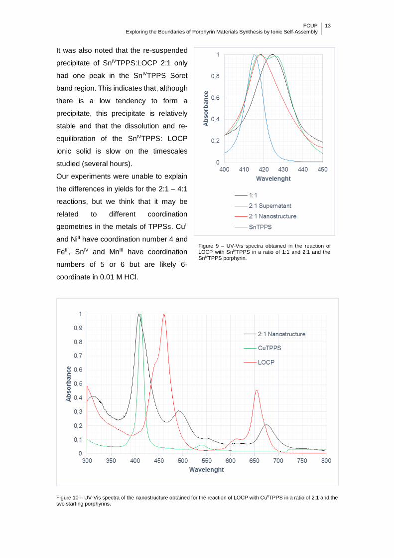
3.1.2. UV-Vis
In all reactions, the absorption bands seen for the precipitate are broadened and either
blue (CuIITPPS) or red (all other porphyrins) shifted relative to the starting materials, but
easily identifiable (Table 4). UV-Vis spectra from the re-suspended precipitates of the
1:2 reactions are shown in Figures 10 to 14.
Table 4 – Main peaks seen in UV-Vis spectra of reactant, and precipitates from reactions of LOCP-TPPS.
LOCP (Soret) MTPPS (Main band)
Starting material 461 412 (CuII), 409 (NiII), 394 (FeIII),
416 (SnIV), 467 (MnIII)
CuIITPPS:LOCP (2) ~492 408
(3)a ~494 411
(4)a ~495 412
NiIITPPS:LOCP (2) ~500 419
(3)a ~498 410
(4)a und 409
FeIIITPPS:LOCP (2) ~500 418
(3) ~500 418
(4) ~500 418
SnIVTPPS:LOCP (2)a ~483 419
(3) ~477 417
(4) 495 417
MnIIITPPS:LOCP (2)a 470b
(3) 470b
(4) 470b
Und = Peak undetermined as it is occluded by other bands; a = trace amounts obtained; b = bands superimposed
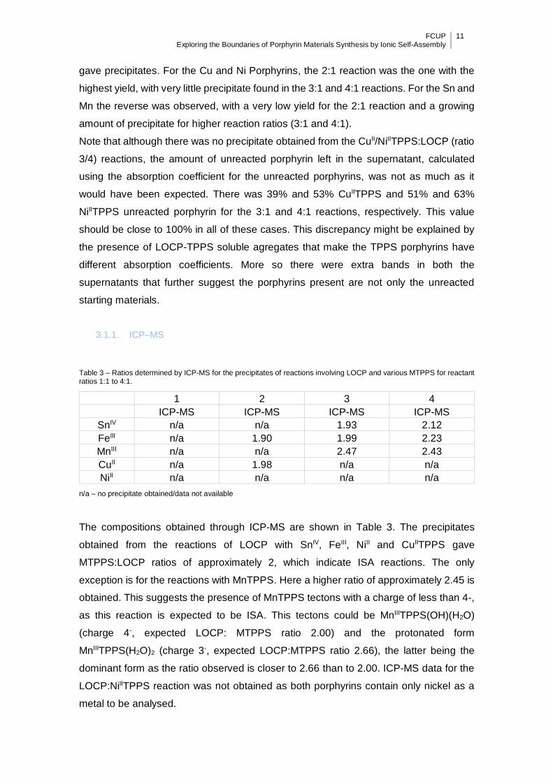
To understand why there where low precipitate yields in the 1:1 reactions and some of
the 2:1 reactions, we analysed the SnTPPS peaks in the 1:1 and 2:1 SnIVTPPS:LOCP
reactions (Figure 9).
As the unreacted porphyrin, SnIVTPPS has a Soret band at 416 nm. In the supernatant
of the 1:1 reaction, the Soret band is at 425 nm, in the re-suspended precipitate of the
2:1 it is at 419 nm and in the supernatant of the 2:1 reaction there are two peaks, one at
418 nm and other at 426 nm. Taken together, these data seem to indicate that the
porphyrin exists in three different states: the free porphyrin (peak at 416 nm), the ionic
solid (peak at 419 nm) and a third state (peak at 425 nm) that probably arises from the
formation of a dimer between SnIVTPPS and LOCP. What may be happening in the 2:1
reaction is that half of the porphyrin is in the form of this dimer (426 nm) and the rest is
either in the unreacted form or is uncentrifugeable.
FCUP Exploring the Boundaries of Porphyrin Materials Synthesis by Ionic Self-Assembly
13
It was also noted that the re-suspended
precipitate of SnIVTPPS:LOCP 2:1 only
had one peak in the SnIVTPPS Soret
band region. This indicates that, although
there is a low tendency to form a
precipitate, this precipitate is relatively
stable and that the dissolution and re-
equilibration of the SnIVTPPS: LOCP
ionic solid is slow on the timescales
studied (several hours).
Our experiments were unable to explain
the differences in yields for the 2:1 – 4:1
reactions, but we think that it may be
related to different coordination
geometries in the metals of TPPSs. CuII
and NiII have coordination number 4 and
FeIII, SnIV and MnIII have coordination
numbers of 5 or 6 but are likely 6-
coordinate in 0.01 M HCl.
Figure 10 – UV-Vis spectra of the nanostructure obtained for the reaction of LOCP with CuIITPPS in a ratio of 2:1 and the two starting porphyrins.
Figure 9 – UV-Vis spectra obtained in the reaction of LOCP with SnIVTPPS in a ratio of 1:1 and 2:1 and the SnIVTPPS porphyrin.
14 FCUP Exploring the Boundaries of Porphyrin Materials Synthesis by Ionic Self-Assembly
Figure 11 – UV-Vis spectra of the nanostructure obtained for the reaction of LOCP with NiIITPPS in a ratio of 2:1 and the two starting porphyrins.
Figure 12 – UV-Vis spectra of the nanostructure obtained for the reaction of LOCP with FeIIITPPS in a ratio of 2:1 and the two starting porphyrins.

FCUP Exploring the Boundaries of Porphyrin Materials Synthesis by Ionic Self-Assembly
15
Figure 13 – UV-Vis spectra of the nanostructure obtained for the reaction of LOCP with SnIVTPPS in a ratio of 2:1 and the two starting porphyrins.
Figure 14 – UV-Vis spectra of the nanostructure obtained for the reaction of LOCP with MnIVTPPS in a ratio of 2:1 and the two starting porphyrins.
16 FCUP Exploring the Boundaries of Porphyrin Materials Synthesis by Ionic Self-Assembly
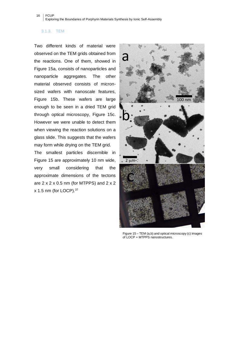
3.1.3. TEM
Two different kinds of material were
observed on the TEM grids obtained from
the reactions. One of them, showed in
Figure 15a, consists of nanoparticles and
nanoparticle aggregates. The other
material observed consists of micron-
sized wafers with nanoscale features,
Figure 15b. These wafers are large
enough to be seen in a dried TEM grid
through optical microscopy, Figure 15c.
However we were unable to detect them
when viewing the reaction solutions on a
glass slide. This suggests that the wafers
may form while drying on the TEM grid.
The smallest particles discernible in
Figure 15 are approximately 10 nm wide,
very small considering that the
approximate dimensions of the tectons
are 2 x 2 x 0.5 nm (for MTPPS) and 2 x 2
x 1.5 nm (for LOCP).37
Figure 15 – TEM (a,b) and optical microscopy (c) images of LOCP + MTPPS nanostructures.
FCUP Exploring the Boundaries of Porphyrin Materials Synthesis by Ionic Self-Assembly
17
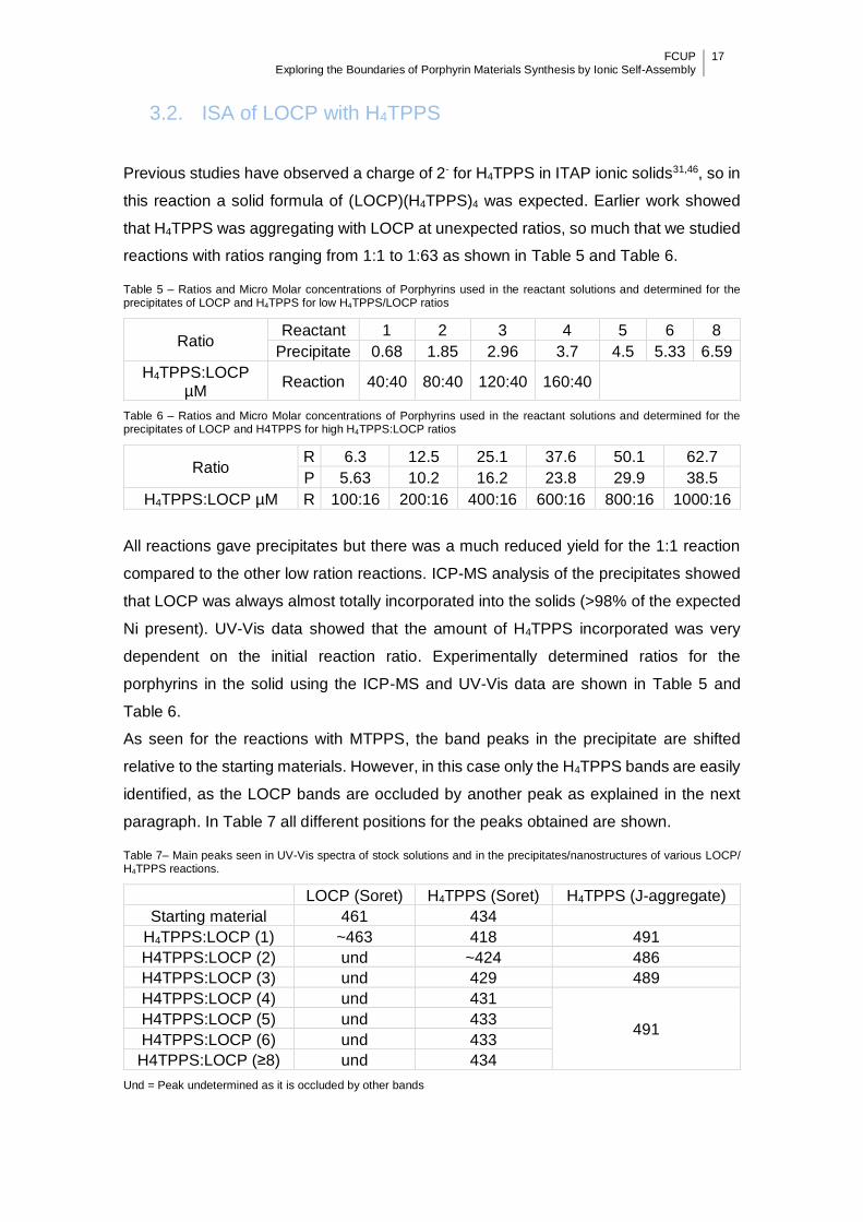
3.2. ISA of LOCP with H4TPPS
Previous studies have observed a charge of 2- for H4TPPS in ITAP ionic solids31,46, so in
this reaction a solid formula of (LOCP)(H4TPPS)4 was expected. Earlier work showed
that H4TPPS was aggregating with LOCP at unexpected ratios, so much that we studied
reactions with ratios ranging from 1:1 to 1:63 as shown in Table 5 and Table 6.
Table 5 – Ratios and Micro Molar concentrations of Porphyrins used in the reactant solutions and determined for the precipitates of LOCP and H4TPPS for low H4TPPS/LOCP ratios
Ratio Reactant 1 2 3 4 5 6 8
Precipitate 0.68 1.85 2.96 3.7 4.5 5.33 6.59
H4TPPS:LOCP µM
Reaction 40:40 80:40 120:40 160:40
Table 6 – Ratios and Micro Molar concentrations of Porphyrins used in the reactant solutions and determined for the precipitates of LOCP and H4TPPS for high H4TPPS:LOCP ratios
Ratio R 6.3 12.5 25.1 37.6 50.1 62.7
P 5.63 10.2 16.2 23.8 29.9 38.5
H4TPPS:LOCP µM R 100:16 200:16 400:16 600:16 800:16 1000:16
All reactions gave precipitates but there was a much reduced yield for the 1:1 reaction
compared to the other low ration reactions. ICP-MS analysis of the precipitates showed
that LOCP was always almost totally incorporated into the solids (>98% of the expected
Ni present). UV-Vis data showed that the amount of H4TPPS incorporated was very
dependent on the initial reaction ratio. Experimentally determined ratios for the
porphyrins in the solid using the ICP-MS and UV-Vis data are shown in Table 5 and
Table 6.
As seen for the reactions with MTPPS, the band peaks in the precipitate are shifted
relative to the starting materials. However, in this case only the H4TPPS bands are easily
identified, as the LOCP bands are occluded by another peak as explained in the next
paragraph. In Table 7 all different positions for the peaks obtained are shown.
Table 7– Main peaks seen in UV-Vis spectra of stock solutions and in the precipitates/nanostructures of various LOCP/ H4TPPS reactions.
LOCP (Soret) H4TPPS (Soret) H4TPPS (J-aggregate)
Starting material 461 434
H4TPPS:LOCP (1) ~463 418 491
H4TPPS:LOCP (2) und ~424 486
H4TPPS:LOCP (3) und 429 489
H4TPPS:LOCP (4) und 431
491 H4TPPS:LOCP (5) und 433
H4TPPS:LOCP (6) und 433
H4TPPS:LOCP (≥8) und 434
Und = Peak undetermined as it is occluded by other bands
18 FCUP Exploring the Boundaries of Porphyrin Materials Synthesis by Ionic Self-Assembly
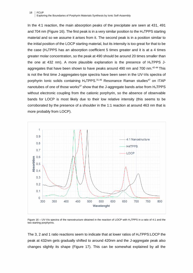
In the 4:1 reaction, the main absorption peaks of the precipitate are seen at 431, 491
and 704 nm (Figure 16). The first peak is in a very similar position to the H4TPPS starting
material and so we assume it arises from it. The second peak is in a position similar to
the initial position of the LOCP starting material, but its intensity is too great for that to be
the case (H4TPPS has an absorption coefficient 5 times greater and it is at a 4 times
greater molar concentration, so the peak at 490 should be around 20 times smaller than
the one at 432 nm). A more plausible explanation is the presence of H4TPPS J-
aggregates that have been shown to have peaks around 490 nm and 700 nm.42-44 This
is not the first time J-aggregates-type spectra have been seen in the UV-Vis spectra of
porphyrin Ionic solids containing H4TPPS.31,46 Resonance Raman studies47 on ITAP
nanotubes of one of those works37 show that the J-aggregate bands arise from H4TPPS
without electronic coupling from the cationic porphyrin, so the absence of observable
bands for LOCP is most likely due to their low relative intensity (this seems to be
corroborated by the presence of a shoulder in the 1:1 reaction at around 463 nm that is
more probably from LOCP).
Figure 16 – UV-Vis spectra of the nanostructure obtained in the reaction of LOCP with H4TPPS in a ratio of 4:1 and the two starting porphyrins.
The 3, 2 and 1 ratio reactions seem to indicate that at lower ratios of H4TPPS:LOCP the
peak at 432nm gets gradually shifted to around 420nm and the J-aggregate peak also
changes slightly its shape (Figure 17). This can be somewhat explained by all the

FCUP Exploring the Boundaries of Porphyrin Materials Synthesis by Ionic Self-Assembly
19
different ways H4TPPS can interact with
LOCP, thanks to the ability of the former
to form J-aggregates. In Figure 18 we can
see two different organizational structures
for the simplest aggregations of H4TPPS
and LOCP, depending on the formation or
not of J-aggregates at a ratio of 2:1. Each
of the possible structures might contribute
to the spectra in a different way and
changes in the relative amount of different
conformations as the ratios change could
account for shifts in the peaks. Figure 19
shows other conformations that are
possible for the reactions with ratio 4. As
the amount of H4TPPS increases, this
porphyrin should have a greater tendency
to surround LOCP and make J-aggregate
arrangements as the ones depicted in
Figure 20.
Note that the structures represented in Figure 18 would need counter ions (Cl-) to reduce
the charge of LOCP to 4+ to be possible in the solid state. To study if this occurred, EDX
was performed to determine the amount of chloride ions present in the solid of the 2:1
reactions (and the 4:1 reactions as a reference point). The results were inconclusive,
likely due to contaminations of the materials with chloride ions from the HCl used in the
synthesis.
Figure 18 – Representation of two hypothetical different aggregation conformations for a reaction between H4TPPS (small diamond shape) and LOCP (large octahedrons) in a 2:1 ratio producing J-aggregates (right) or not (left).
Figure 17 – UV-Vis spectra of the nanostructure obtained
in the reaction of LOCP with H4TPPS in ratios1 to 4.
20 FCUP Exploring the Boundaries of Porphyrin Materials Synthesis by Ionic Self-Assembly
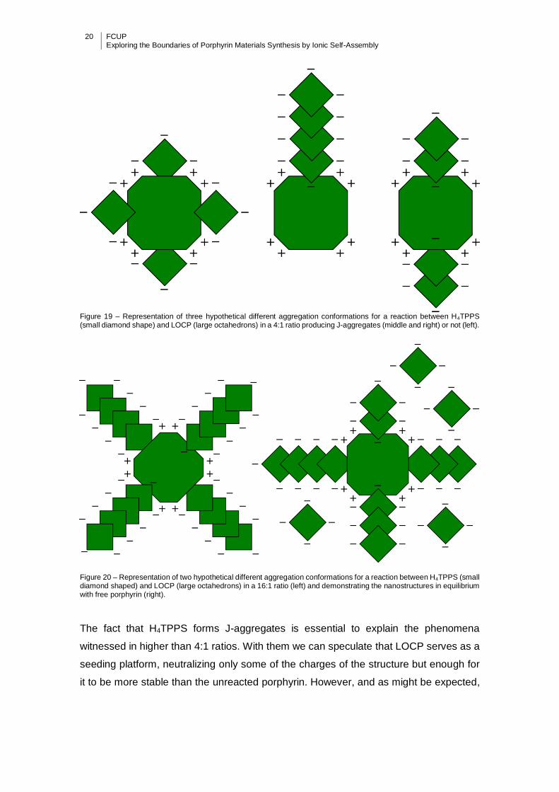
Figure 19 – Representation of three hypothetical different aggregation conformations for a reaction between H4TPPS (small diamond shape) and LOCP (large octahedrons) in a 4:1 ratio producing J-aggregates (middle and right) or not (left).
Figure 20 – Representation of two hypothetical different aggregation conformations for a reaction between H4TPPS (small diamond shaped) and LOCP (large octahedrons) in a 16:1 ratio (left) and demonstrating the nanostructures in equilibrium with free porphyrin (right).
The fact that H4TPPS forms J-aggregates is essential to explain the phenomena
witnessed in higher than 4:1 ratios. With them we can speculate that LOCP serves as a
seeding platform, neutralizing only some of the charges of the structure but enough for
it to be more stable than the unreacted porphyrin. However, and as might be expected,
FCUP Exploring the Boundaries of Porphyrin Materials Synthesis by Ionic Self-Assembly
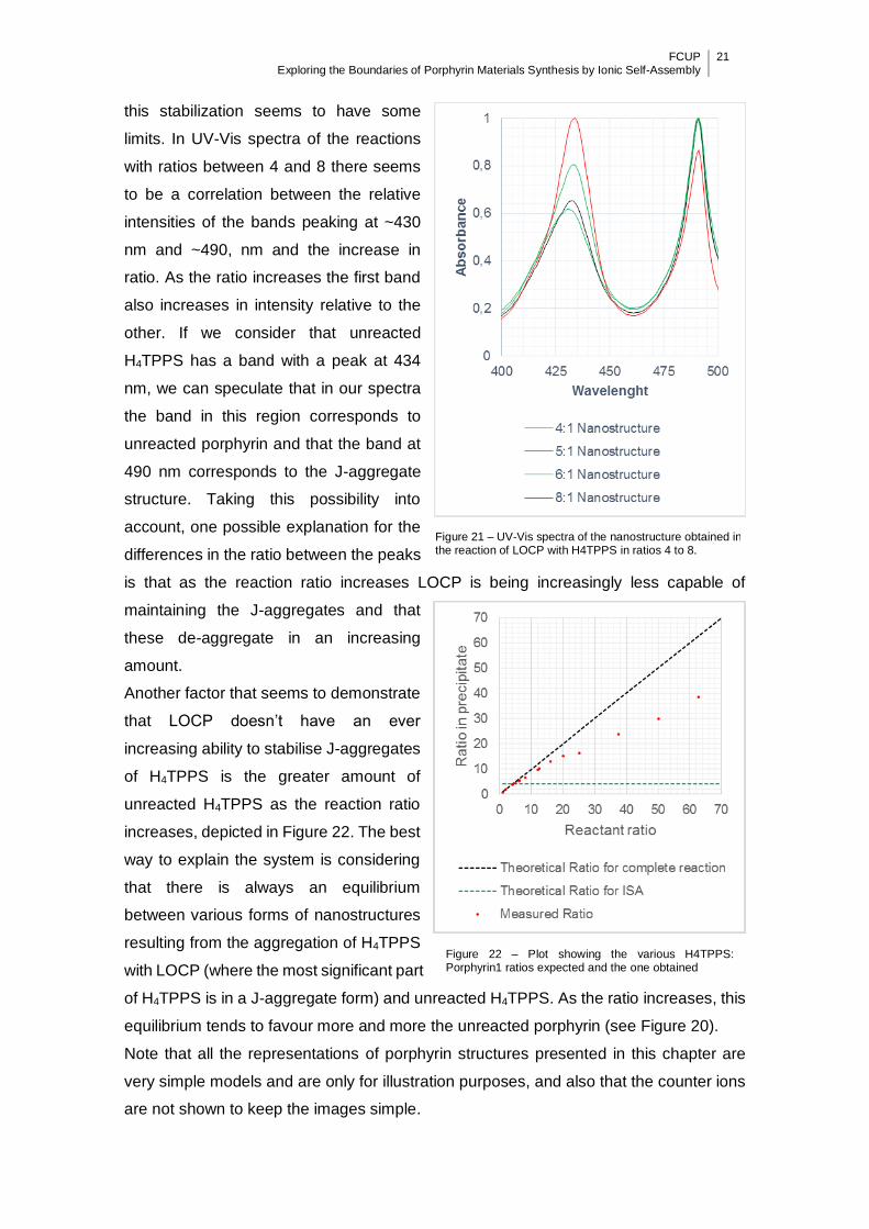
21
this stabilization seems to have some
limits. In UV-Vis spectra of the reactions
with ratios between 4 and 8 there seems
to be a correlation between the relative
intensities of the bands peaking at ~430
nm and ~490, nm and the increase in
ratio. As the ratio increases the first band
also increases in intensity relative to the
other. If we consider that unreacted
H4TPPS has a band with a peak at 434
nm, we can speculate that in our spectra
the band in this region corresponds to
unreacted porphyrin and that the band at
490 nm corresponds to the J-aggregate
structure. Taking this possibility into
account, one possible explanation for the
differences in the ratio between the peaks
is that as the reaction ratio increases LOCP is being increasingly less capable of
maintaining the J-aggregates and that
these de-aggregate in an increasing
amount.
Another factor that seems to demonstrate
that LOCP doesn’t have an ever
increasing ability to stabilise J-aggregates
of H4TPPS is the greater amount of
unreacted H4TPPS as the reaction ratio
increases, depicted in Figure 22. The best
way to explain the system is considering
that there is always an equilibrium
between various forms of nanostructures
resulting from the aggregation of H4TPPS
with LOCP (where the most significant part
of H4TPPS is in a J-aggregate form) and unreacted H4TPPS. As the ratio increases, this
equilibrium tends to favour more and more the unreacted porphyrin (see Figure 20).
Note that all the representations of porphyrin structures presented in this chapter are
very simple models and are only for illustration purposes, and also that the counter ions
are not shown to keep the images simple.
Figure 21 – UV-Vis spectra of the nanostructure obtained in the reaction of LOCP with H4TPPS in ratios 4 to 8.
Figure 22 – Plot showing the various H4TPPS: Porphyrin1 ratios expected and the one obtained
22 FCUP Exploring the Boundaries of Porphyrin Materials Synthesis by Ionic Self-Assembly
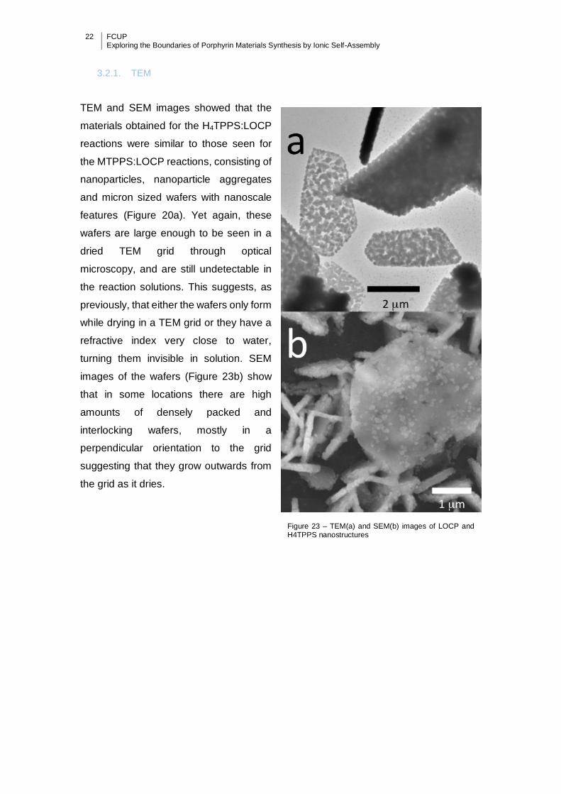
3.2.1. TEM
TEM and SEM images showed that the
materials obtained for the H4TPPS:LOCP
reactions were similar to those seen for
the MTPPS:LOCP reactions, consisting of
nanoparticles, nanoparticle aggregates
and micron sized wafers with nanoscale
features (Figure 20a). Yet again, these
wafers are large enough to be seen in a
dried TEM grid through optical
microscopy, and are still undetectable in
the reaction solutions. This suggests, as
previously, that either the wafers only form
while drying in a TEM grid or they have a
refractive index very close to water,
turning them invisible in solution. SEM
images of the wafers (Figure 23b) show
that in some locations there are high
amounts of densely packed and
interlocking wafers, mostly in a
perpendicular orientation to the grid
suggesting that they grow outwards from
the grid as it dries.
Figure 23 – TEM(a) and SEM(b) images of LOCP and H4TPPS nanostructures
FCUP Exploring the Boundaries of Porphyrin Materials Synthesis by Ionic Self-Assembly
23
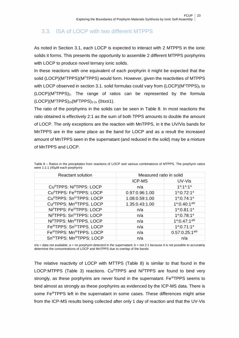
3.3. ISA of LOCP with two different MTPPS
As noted in Section 3.1, each LOCP is expected to interact with 2 MTPPS in the ionic
solids it forms. This presents the opportunity to assemble 2 different MTPPS porphyrins
with LOCP to produce novel ternary ionic solids.
In these reactions with one equivalent of each porphyrin it might be expected that the
solid (LOCP)(M1TPPS)(M2TPPS) would form. However, given the reactivities of MTPPS
with LOCP observed in section 3.1. solid formulas could vary from (LOCP)(M1TPPS)2 to
(LOCP)(M2TPPS)2. The range of ratios can be represented by the formula
(LOCP)(M1TPPS)2x(M2TPPS)2-2x (0≤x≤1).
The ratio of the porphyrins in the solids can be seen in Table 8. In most reactions the
ratio obtained is effectively 2:1 as the sum of both TPPS amounts to double the amount
of LOCP. The only exceptions are the reaction with MnTPPS, in it the UV/Vis bands for
MnTPPS are in the same place as the band for LOCP and as a result the increased
amount of MnTPPS seen in the supernatant (and reduced in the solid) may be a mixture
of MnTPPS and LOCP.
Table 8 – Ratios in the precipitates from reactions of LOCP and various combinations of MTPPS. The porphyrin ratios were 1:1:1 (40µM each porphyrin)
Reactant solution Measured ratio in solid
ICP-MS UV-Vis
CuIITPPS: NiIITPPS: LOCP n/a 1a:1a:1a
CuIITPPS: FeIIITPPS: LOCP 0.97:0.96:1.00 1a:0.72:1a
CuIITPPS: SnIVTPPS: LOCP 1.08:0.59:1.00 1a:0.74:1a
CuIITPPS: MnIIITPPS. LOCP 1.35:0.43:1.00 1a:0.40:1a/b
NiIITPPS: FeIIITPPS: LOCP n/a 1a:0.81:1a
NiIITPPS: SnIVTPPS: LOCP n/a 1a:0.78:1a
NiIITPPS: MnIIITPPS. LOCP n/a 1a:0.47:1a/b
FeIIITPPS: SnIVTPPS. LOCP n/a 1a:0.71:1a
FeIIITPPS: MnIIITPPS. LOCP n/a 0.57:0.25:1a/b
SnIVTPPS: MnIIITPPS: LOCP n/a n/a
n/a = data not available; a = no porphyrin detected in the supernatant; b = not 2:1 because it is not possible to accurately determine the concentrations of LOCP and MnTPPS due to overlap of the bands
The relative reactivity of LOCP with MTTPS (Table 8) is similar to that found in the
LOCP:MTPPS (Table 3) reactions. CuIITPPS and NiIITPPS are found to bind very
strongly, as these porphyrins are never found in the supernatant. FeIIITPPS seems to
bind almost as strongly as these porphyrins as evidenced by the ICP-MS data. There is
some FeIIITPPS left in the supernatant in some cases. These differences might arise
from the ICP-MS results being collected after only 1 day of reaction and that the UV-Vis

24 FCUP Exploring the Boundaries of Porphyrin Materials Synthesis by Ionic Self-Assembly
results are from a week of reaction. The other porphyrins (SnIVTPPS/MnIIITPPS) bind to
a lesser extent but they all are included somewhat in the precipitate. This is contrary to
what is observed for the MTPPS:LOCP reaction in a 2:1 ratio where these
metalcomplexes produce very little precipitate, perhaps because there is a cooperative
binding effect in the ternary system.
The UV/Vis spectra of the precipitates are compared with the 2:1 reactions and are
shown in Figures 24 to 33. In all reactions the LOCP band has a large red-shift compared
to the starting material (as seen in section 3.1.). There are frequent overlaps of various
Soret bands for the TPPS complexes, in fact the main band for MnIIITPPS is the only one
clearly distinguishable from the others. The broad soret band of FeIIITPPS:LOCP is not
visible excepting in the FeIIITPP:MnIIITPPS:LOCP where FeIIITPPS is the dominant
species. A better comparison between the main bands and their shifts can be seen in
Table 9. The reaction NiIITPPS:SnIVTPPS:LOCP has an extra peak at 439 nm but this
can be explained by the fact that this reaction was mistakenly made at pH 1 instead of
pH 2. A similar peak was seen in a different CuIITPPS:SnIVTPPS:LOCP reaction not
shown in the graphs. This reaction was also made at pH1 but the peak disappeared at
pH 2.
EDX was performed to try and determine if both MTPPS here indeed mixed in the same
nanostructures but the results were inconclusive because of the lack of sensitivity.
Table 9 – Main peaks seen in UV-Vis spectra of reactant and in the precipitates from reactions of LOCP with M1TPPS and M2TPPS.
Und = Peak undetermined as it is occluded by other bands; a = extra band present due to the reaction being carried out at pH 1
LOCP (Soret) MTPPS (Main band)
Starting material 461 412 (CuII), 409 (NiII), 394
(FeIII), 416 (SnIV), 467 (MnIII)
CuIITPPS: LOCP (2:1) ~492 408
NiIITPPS: LOCP (2:1) ~500 419
FeIIITPPS: LOCP (2:1) und 417
SnIVTPPS: LOCP (2:1) ~472 417
MnIIITPPS: LOCP (2:1) 470
CuIITPPS: NiIITPPS: LOCP (1:1:1) ~498 416 (CuII & NiII)
CuIITPPS: FeIIITPPS: LOCP (1:1:1) ~493 412
CuIITPPS: SnIVTPPS. LOCP (1:1:1) ~496 416 (CuII & SnIV)
CuIITPPS: MnIIITPPS: LOCP (1:1:1) und 412 (CuII), 474 (MnIII)
NiIITPPS: FeIIITPPS: LOCP (1:1:1) 497 418 (NiII)
NiIITPPS: SnIVTPPS: LOCP (1:1:1) 497 416, 439a
NiIITPPS: MnIIITPPS: LOCP (1:1:1) und 418 (NiII), 470 (MnII)
FeIIITPPS: SnIVTPPS: LOCP (1:1:1) ~498 423
FeIIITPPS: MnIIITPPS: LOCP (1:1:1) und 417(FeIII), 467 (MnIII)
SnIVTPPS: MnIIITPPS: LOCP (1:1:1) ~498 418(SnIV),467 (MnIII)

FCUP Exploring the Boundaries of Porphyrin Materials Synthesis by Ionic Self-Assembly
25
Figure 24 – UV-Vis spectra of the nanostructure obtained in the reaction of LOCP with CuTPPS and NiTPPS (1:1:1 ratio) compared with the UV-Vis spectra of the nanostructures of the reactions of LOCP with CuTPPS (1:2 ratio) or NiTPPS (1:2 ratio).
Figure 25 – UV-Vis spectra of the nanostructure obtained in the reaction of LOCP with CuTPPS and FeTPPS (1:1:1 ratio) compared with the UV-Vis spectra of the nanostructures of the reactions of LOCP with CuTPPS (1:2 ratio) or FeTPPS (1:2 ratio).
26 FCUP Exploring the Boundaries of Porphyrin Materials Synthesis by Ionic Self-Assembly
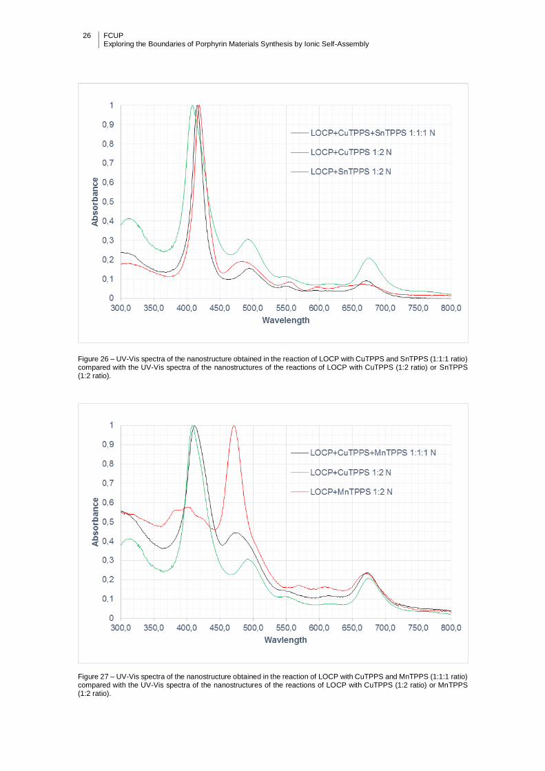
Figure 26 – UV-Vis spectra of the nanostructure obtained in the reaction of LOCP with CuTPPS and SnTPPS (1:1:1 ratio) compared with the UV-Vis spectra of the nanostructures of the reactions of LOCP with CuTPPS (1:2 ratio) or SnTPPS (1:2 ratio).
Figure 27 – UV-Vis spectra of the nanostructure obtained in the reaction of LOCP with CuTPPS and MnTPPS (1:1:1 ratio) compared with the UV-Vis spectra of the nanostructures of the reactions of LOCP with CuTPPS (1:2 ratio) or MnTPPS (1:2 ratio).

FCUP Exploring the Boundaries of Porphyrin Materials Synthesis by Ionic Self-Assembly
27
Figure 28 – UV-Vis spectra of the nanostructure obtained in the reaction of LOCP with NiTPPS and FeTPPS (1:1:1 ratio) compared with the UV-Vis spectra of the nanostructures of the reactions of LOCP with NiTPPS (1:2 ratio) or FeTPPS (1:2 ratio).
Figure 29 – UV-Vis spectra of the nanostructure obtained in the reaction of LOCP with NiTPPS and SnTPPS (1:1:1 ratio) compared with the UV-Vis spectra of the nanostructures of the reactions of LOCP with NiTPPS (1:2 ratio) or SnTPPS (1:2 ratio). Note: Reaction done at pH 1 and this results in the extra Soret band at 439 nm.

28 FCUP Exploring the Boundaries of Porphyrin Materials Synthesis by Ionic Self-Assembly
Figure 30 – UV-Vis spectra of the nanostructure obtained in the reaction of LOCP with NiTPPS and MnTPPS (1:1:1 ratio) compared with the UV-Vis spectra of the nanostructures of the reactions of LOCP with NiTPPS (1:2 ratio) or MnTPPS (1:2 ratio).
Figure 31 – UV-Vis spectra of the nanostructure obtained in the reaction of LOCP with FeTPPS and SnTPPS (1:1:1 ratio) compared with the UV-Vis spectra of the nanostructures of the reactions of LOCP with FeTPPS (1:2 ratio) or SnTPPS (1:2 ratio).
FCUP Exploring the Boundaries of Porphyrin Materials Synthesis by Ionic Self-Assembly
29
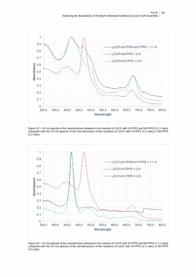
Figure 32 – UV-Vis spectra of the nanostructure obtained in the reaction of LOCP with FeTPPS and MnTPPS (1:1:1 ratio) compared with the UV-Vis spectra of the nanostructures of the reactions of LOCP with FeTPPS (1:2 ratio) or MnTPPS (1:2 ratio).
Figure 33 – UV-Vis spectra of the nanostructure obtained in the reaction of LOCP with SnTPPS and MnTPPS (1:1:1 ratio) compared with the UV-Vis spectra of the nanostructures of the reactions of LOCP with SnTPPS (1:2 ratio) or MnTPPS (1:2 ratio).
30 FCUP Exploring the Boundaries of Porphyrin Materials Synthesis by Ionic Self-Assembly
3.3.1. TEM
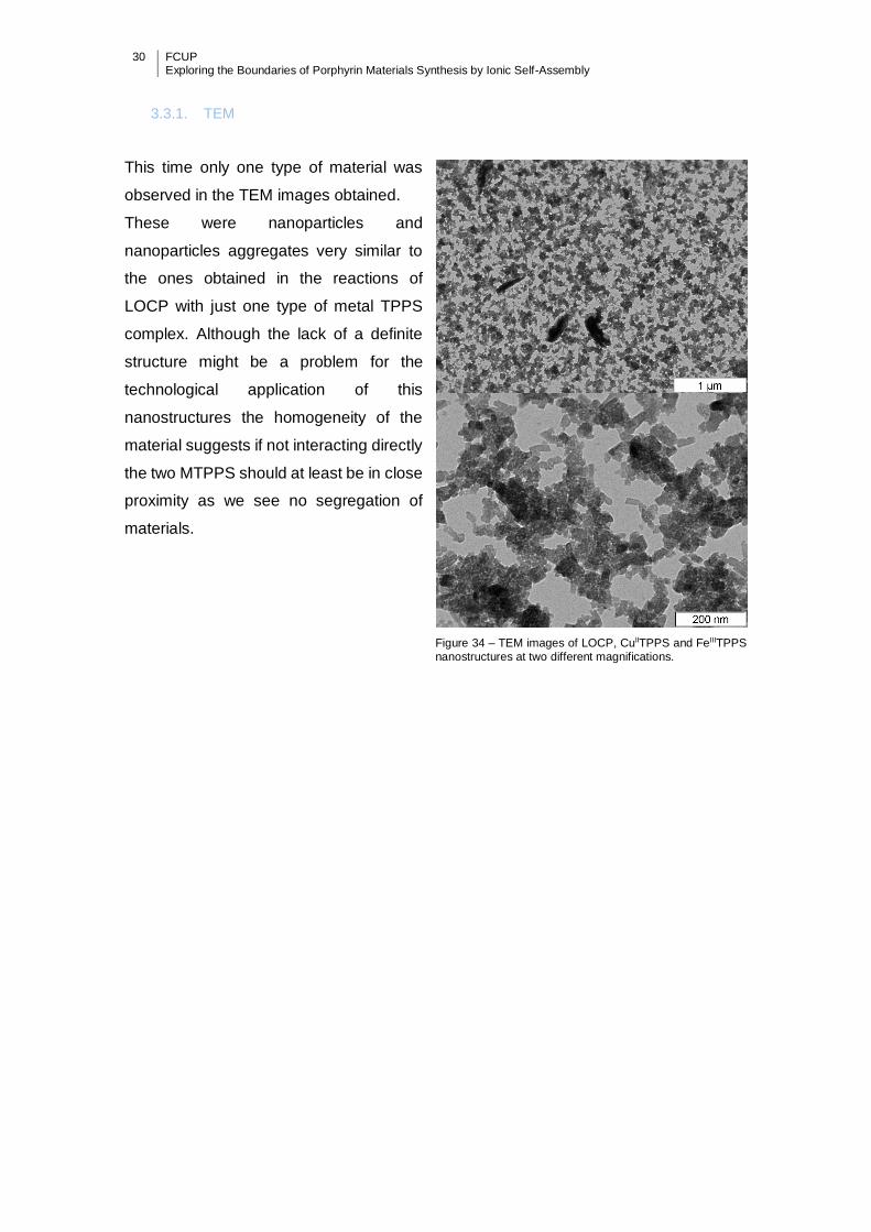
This time only one type of material was
observed in the TEM images obtained.
These were nanoparticles and
nanoparticles aggregates very similar to
the ones obtained in the reactions of
LOCP with just one type of metal TPPS
complex. Although the lack of a definite
structure might be a problem for the
technological application of this
nanostructures the homogeneity of the
material suggests if not interacting directly
the two MTPPS should at least be in close
proximity as we see no segregation of
materials.
Figure 34 – TEM images of LOCP, CuIITPPS and FeIIITPPS
nanostructures at two different magnifications.

FCUP Exploring the Boundaries of Porphyrin Materials Synthesis by Ionic Self-Assembly
31
4. Conclusions
It was possible to carry out Self-assembly of LOCP and TPPS, although the reactions
studied did not perform in the way predicted for classical ionic self-assembly, as shown
in the previous chapters. If the reaction between MTPPS, H4TPPS and LOCP had
followed classical ISA rules all reaction ratios would have given precipitates with ratios
of 2:1 (MTPPS) and 4:1 (H4TPPS), with the exception of those with MnIIITPPS due to the
possibility of it having charge 3- or 4- (expected ratio between 2.66:1 and 2.00:1
respectively). In the next paragraphs the results obtained are discussed.
For the MTPPS reactions, in the 2/3/4:1 ratio reactions there was a clear division
between the behaviour of Ni/CuTPPS and Fe/Sn/MnTPPS. The former had a complete
reaction in a 2:1 ratio and forming almost no precipitate in the 3/4:1 reactions, and the
latter had the opposite behaviour, with almost no precipitate in the 2:1 reaction and
increasing amounts of precipitates in the 3/4:1 reactions. One possible explanation for
this behaviour is the differences of coordination number and geometry that each of the
metals has in the centre of the porphyrin. Ni and Cu are 4 coordinated and have a square
planar geometry that might impede the connection of additional ligands besides the
internal Nitrogen of TPPS. In contrast Mn, Sn, and Fe can be 5 or 6 coordinated and
have either square pyramidal or octahedral geometries that give them the ability to ligate
one or two extra ligands. However, the mechanism by which the axial ligands modulate
the ability of MTPPS to interact with LOCP or other MTPPS molecules in the ionic solid
to produce the observed reactivities is unknown. In the 1:1 ratios reactions there were
no precipitates whatsoever, likely due to the formation of soluble MTPPS-LOCP dimers.
Even though there were differences between various MTPPS reactions with LOCP, all
TEM images obtained revealed two different types of materials obtained, micro sheets
or nanoparticles (that form some aggregates) regardless of the metal.
The H4TPPS reactions with LOCP were clearly not classical ISA, as the solids obtained
in the reactions did not have a fixed ratio (expected to be 4:1). Instead, the solids
obtained had a ratio that was always dependent on the starting material ratio. The
reactions suggested an equilibrium between the unreacted porphyrins and the solid, the
former becoming more favoured at higher H4TPPS to LOCP ratios. Although not being
made through classical ISA, the materials observed with TEM seemed to be very similar
to the ones from the MTPPS reactions, suggesting that the most important factor for the
shape of the materials formed in this reaction is the TPPS structure and not the presence
of various metals or the way through which the porphyrins come together. This is
surprising after taking into account all the differences and the fact that the H4TPPS:LOCP
32 FCUP Exploring the Boundaries of Porphyrin Materials Synthesis by Ionic Self-Assembly
solids may not even be binary ionic solids, as counter ions should be present in the solids
at lower than 4:1 ratios and excess H4TPPS in reactions with >4:1 ratios.
In the double-metal reactions with LOCP we obtained solids with an expected 2:1 ratio.
These reactions might seem the ones having a behaviour most similar to a classical ISA
but as the reactions were only attempted in a 2:1 ratio (1 M1TPPS + 1 M2TPPS: 1LOCP)
there is not enough data to be certain. It could be that different ratios such as the ones
tried in the single MTPPS:LOCP reactions might show this reaction to be just as unusual
as those previously discussed. It should be noted that the most important element of
these reactions is that they are capable of producing precipitates in which the high
charge of a porphyrin (LOCP) is used to make it react with two different oppositely
charged porphyrins (MTPPS). Here, the TEM images reveal only a single type of material
similar to the particle and particle aggregate structures obtained for the other two types
of reactions. Of particular interest here is that there is no visible separation of materials
and so there is no obvious segregation between materials formed from MTPPS-LOCP
reactions. Note that there are no large structures which hindered attempts to use EDX
analysis to determine if the two MTPPS were actually coexisting in the same
nanostructure.
Various other reactions are being tried as follow-ups to the work discussed in this thesis.
The more clear follow-ups are the mixture of LOCP with MTPPS and H4TPPS in the
same reaction either in a competitive system (ratio 4:2:1 H4TPPS:MTPPS:LOCP) or in
an attempt to form stoichiometric solids (ratio 2:1:1 H4TPPS:MTPPS:LOCP), as this may
give us the opportunity to better understand the reactions of LOCP. Different ratios for
the two MTPPS:LOCP reaction will be used to try and determine if these reactions really
follow classical ISA or only seem that way because of the ratios used so far. Other follow-
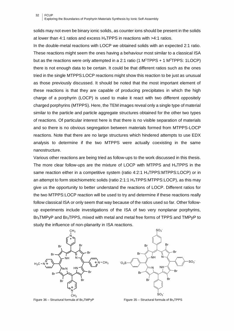
up experiments include investigations of the ISA of two very nonplanar porphyrins,
Br8TMPyP and Br8TPPS, mixed with metal and metal free forms of TPPS and TMPyP to
study the influence of non-planarity in ISA reactions.
Figure 36 – Structural formula of Br8TMPyP Figure 35 – Structural formula of Br8TPPS

FCUP Exploring the Boundaries of Porphyrin Materials Synthesis by Ionic Self-Assembly
33
5. References
1 Fischer, H. & Gleim, W. Synthese des Porphins. Justus Liebig's Annalen der
Chemie 521, 157-160, doi:10.1002/jlac.19365210110 (1936).
2 Rothemund, P. Formation of Porphyrins from Pyrrole and Aldehydes. Journal of
the American Chemical Society 57, 2010-2011, doi:10.1021/ja01313a510
(1935).
3 Rothemund, P. A New Porphyrin Synthesis. The Synthesis of Porphin1. Journal
of the American Chemical Society 58, 625-627, doi:10.1021/ja01295a027 (1936).
4 Adler, A. D. et al. A simplified synthesis for meso-tetraphenylporphine. The
Journal of Organic Chemistry 32, 476-476, doi:10.1021/jo01288a053 (1967).
5 Petit, A., Loupy, A., Maiuardb, P. & Momenteaub, M. Microwave Irradiation in Dry
Media: A New and Easy Method for Synthesis of Tetrapyrrolic Compounds.
Synthetic Communications 22, 1137-1142, doi:10.1080/00397919208021097
(1992).
6 Drain, C. M. & Gong, X. Synthesis of meso substituted porphyrins in air without
solvents or catalysts. Chemical Communications, 2117-2118,
doi:10.1039/a704600f (1997).
7 George, P. Critique of the resonance energy concept with particular reference to
nitrogen heterocycles, especially porphyrins. Chemical Reviews 75, 85-111,
doi:10.1021/cr60293a004 (1975).
8 Spoehr, H. A. Chemical Aspects of Photosynthesis. Annual Review of
Biochemistry 2, 453-470, doi:10.1146/annurev.bi.02.070133.002321 (1933).
9 Mauzerall, D. in Photosynthesis I Vol. 5 Encyclopedia of Plant Physiology (eds
A. Trebst & M. Avron) Ch. 5, 117-124 (Springer Berlin Heidelberg, 1977).
10 Mense, S. M. & Zhang, L. Heme: a versatile signaling molecule controlling the
activities of diverse regulators ranging from transcription factors to MAP kinases.
Cell Research 16, 681-692, doi:10.1038/sj.cr.7310086 (2006).
11 Wormald, R., Evans, J. R., Smeeth, L. L. & Henshaw, K. S. Photodynamic
therapy for neovascular age‐related macular degeneration. The Cochrane
Library, CD002030, doi:10.1002/14651858.CD002030.pub3 (2007).
12 Lourenço, C. M., Lee, C. & Anderson, K. E. Disorders of Haem Biosynthesis.
Inborn Metabolic Diseases (2012).
13 Hardin, B. E., Snaith, H. J. & McGehee, M. D. The renaissance of dye-sensitized
solar cells. Nat Photonics 6, 162-169, doi:10.1038/nphoton.2012.22 (2012).

34 FCUP Exploring the Boundaries of Porphyrin Materials Synthesis by Ionic Self-Assembly
14 Walter, M. G., Rudine, A. B. & Wamser, C. C. Porphyrins and phthalocyanines in
solar photovoltaic cells. Journal of Porphyrins and Phthalocyanines 14, 759-792,
doi:10.1142/S1088424610002689 (2010).
15 Yella, A. et al. Porphyrin-sensitized solar cells with cobalt (II/III)-based redox
electrolyte exceed 12 percent efficiency. Science 334, 629-634,
doi:10.1126/science.1209688 (2011).
16 Chen, C.-T. Evolution of Red Organic Light-Emitting Diodes: Materials and
Devices. Chem Mater 16, 4389-4400, doi:10.1021/cm049679m (2004).
17 Holten, D., Bocian, D. F. & Lindsey, J. S. Probing electronic communication in
covalently linked multiporphyrin arrays. A guide to the rational design of
molecular photonic devices. Accounts Chem Res 35, 57-69, doi:DOI
10.1021/ar970264z (2002).
18 Sun, S.-S. & Dalton, L. R. Introduction to organic electronic and optoelectronic
materials and devices. (CRC Press, 2008).
19 Mikkelsen, M., Jørgensen, M. & Krebs, F. C. The teraton challenge. A review of
fixation and transformation of carbon dioxide. Energ Environ Sci 3, 43-81,
doi:10.1039/b912904a (2010).
20 Zucca, P., Rescigno, A., Rinaldi, A. C. & Sanjust, E. Biomimetic metalloporphines
and metalloporphyrins as potential tools for delignification: Molecular
mechanisms and application perspectives. Journal of Molecular Catalysis A:
Chemical 388-389, 2-34, doi:10.1016/j.molcata.2013.09.010 (2014).
21 Lee, S. J., Hupp, J. T. & Nguyen, S. T. Growth of narrowly dispersed porphyrin
nanowires and their hierarchical assembly into macroscopic columns. Journal of
the American Chemical Society 130, 9632-9633, doi:10.1021/ja801733t (2008).
22 Lee, S. J. et al. Effect of secondary substituent on the physical properties, crystal
structures, and nanoparticle morphologies of (porphyrin)Sn(OH)2: diversity
enabled via synthetic manipulations. Journal of Materials Chemistry 18, 3640,
doi:10.1039/b804629h (2008).
23 Lee, S. J., Malliakas, C. D., Kanatzidis, M. G., Hupp, J. T. & Nguyen, S. T.
Amphiphilic Porphyrin Nanocrystals: Morphology Tuning and Hierarchical
Assembly. Adv Mater 20, 3543-3549, doi:10.1002/adma.200800003 (2008).
24 Wang, Z., Li, Z., Medforth, C. J. & Shelnutt, J. A. Self-assembly and self-
metallization of porphyrin nanosheets. Journal of the American Society 129,
2440-2441, doi:10.1021/ja068250o (2007).
25 Hu, J. S., Guo, Y. G., Liang, H. P., Wan, L. J. & Jiang, L. Three-dimensional self-
organization of supramolecular self-assembled porphyrin hollow hexagonal
FCUP Exploring the Boundaries of Porphyrin Materials Synthesis by Ionic Self-Assembly
35
nanoprisms. Journal of the American Society 127, 17090-17095,
doi:10.1021/ja0553912 (2005).
26 Wang, Z. et al. Monodisperse porphyrin nanospheres synthesized by
coordination polymerization. Nanotechnology 19, 395604, doi:10.1088/0957-
4484/19/39/395604 (2008).
27 La, T., Richards, R. A., Lu, R. S., Bau, R. & Miskelly, G. M. Solution Chemistry
and Crystal Structure of Nickel Tetrakis(2,3,5,6-tetrafluoro-N,N,N-trimethyl-4-
aniliniumyl)porphyrin Trifluoromethanesulfonate (NiTF4TMAP(CF3SO3)4). Inorg
Chem 34, 5632-5640, doi:10.1021/ic00126a037 (1995).
28 Ivanca, M. A., Lappin, A. G. & Scheidt, W. R. Water-soluble ferric porphyrinates:
solution and solid-state species. Inorg Chem 30, 711-718,
doi:10.1021/ic00004a022 (1991).
29 Kanemitsu, H., Harada, R. & Ogo, S. A water-soluble iridium (III) porphyrin.
Chem. Commun. 46, 3083-3085, doi:10.1039/C000263A (2010).
30 Faul, C. F. J. & Antonietti, M. Ionic Self-Assembly: Facile Synthesis of
Supramolecular Materials. Adv Mater 15, 673-683,
doi:10.1002/adma.200300379 (2003).
31 Wang, Z., Medforth, C. J. & Shelnutt, J. A. Porphyrin nanotubes by ionic self-
assembly. J Am Chem Soc 126, 15954-15955, doi:10.1021/ja045068j (2004).
32 Mongwaketsi, N., Khamlich, S. & Klumperman, B. Synthesis and characterization
of porphyrin nanotubes/rods for solar radiation harvesting and solar cells. Physica
B: Condensed … (2012).
33 Wang, Z., Ho, K. J., Medforth, C. J. & Shelnutt, J. A. Porphyrin nanofiber bundles
from phase-transfer ionic self-assembly and their photocatalytic self-
metallization. Adv. Mater. 18, 2557-2560 (2006).
34 Martin, K. E. et al. Donor-acceptor biomorphs from the ionic self-assembly of
porphyrins. Journal of American Chemical Society 132, 8194-8201,
doi:10.1021/ja102194x (2010).
35 Tian, Y. et al. Binary ionic porphyrin nanosheets: electronic and light-harvesting
properties regulated by crystal structure. Nanoscale 4, 1695-1700,
doi:10.1039/C2NR11826B (2012).
36 Medforth, C. J. et al. Self-assembled porphyrin nanostructures. Chem. Commun.,
7261-7277, doi:10.1039/B914432C (2009).
37 Jiang, L. et al. Water-soluble ionic benzoporphyrins. Chemical Communications
48, 6927-6929, doi:10.1039/C2CC31057K (2012).
38 Linnell, R. Notes- Dissociation Constants of 2-Substituted Pyridines. The Journal
of Organic Chemistry 25, 290-290, doi:10.1021/jo01072a623 (1960).
36 FCUP Exploring the Boundaries of Porphyrin Materials Synthesis by Ionic Self-Assembly
39 Guthrie, J. P. Hydrolysis of esters of oxy acids: pKavalues for strong acids;
Brønsted relationship for attack of water at methyl; free energies of hydrolysis of
esters of oxy acids; and a linear relationship between free energy of hydrolysis
and pKaholding over a range of 20pKunits. Canadian Journal of Chemistry 56,
2342-2354, doi:10.1139/v78-385 (1978).
40 Tabata, M. & Tanaka, M. A new method for the determination of the stability
constant of metalloporphyrins: use of the catalytic effect of mercury(II) on
metalloprophyrin formation. Journal of the Chemical Society, Chemical
Communications, 42, doi:10.1039/c39850000042 (1985).
41 Stone, A. & Fleischer, E. B. TPP dication structures. J. Am. Chem. Soc. 90, 2735-
2748 (1968).
42 Schwab, A. D. et al. Porphyrin nanorods. J. Phys. Chem. B 107, 11339-11345
(2003).
43 Pasternack, R. F. et al. On the aggregation of meso-substituted water-soluble
porphyrins. J. Am. Chem. Soc. 94, 4511-4517 (1972).
44 Friesen, B. A., Nishida, K. R. A., McHale, J. L. & Mazur, U. New Nanoscale
Insights into the Internal Structure of Tetrakis(4-sulfonatophenyl) Porphyrin
Nanorods. J. Phys. Chem. C 113, 1709 (2009).
45 Martin, K. E. et al. Charge Effects on the Structure and Composition of Porphyrin
Binary Ionic Solids: ZnTPPS/SnTMePyP Nanomaterials. Chem Mater 25, 441-
447, doi:10.1021/cm303595s (2013).
46 Jacobsen, J. L. et al. Synthesis and nanostructures of 5,10,15,20-tetrakis(4-
piperidyl)porphyrin. Tetrahedron 69, 10507-10515, doi:10.1016/j.tet.2013.09.055
(2013).
47 Franco, R. et al. Internal Organization and Electronic Structure of Porphyrin
Nanotubes Revealed by Resonance Raman Spectroscopy. Phys. Chem. Chem.
Phys. 12, 4072 (2010).