Embed Size (px)
Citation preview

http://f3j.in.ua

Blaster 3 – Assembly Manual http://f3j.in.ua
1. Bill Of Materials ……………………………………………………………32. 7 Assembly steps
1) Glue ailerons & rudder control horns ….……………………… 42) Install radio gear .…………………………………………………53) Install aileron pushrods ..…………………………………………64) Install horizontal & vertical stabilizers ….………………………75) Install elevator & rudder pushrods …..………………………… 86) Glue the launching peg...………………………………………… 97) Set up the plane ..…………………………………………………10
3. Fly it!
2

4) Pen and ruler5) 240…320 grit sandpaper3) Pliers
1) Thin and Medium CA, CA kicker2) Hobby knife3) Masking tape
9) Rudder control horn10) Front wing mounting screw М3х8 (2 pieces, 1 spare)11) Rear wing mounting screw М3х6 (2 pieces, 1 spare)12) Horiz. Stabilizer washer (2pieces, 1 spare)13) Clevises14) Aileron pushrods15) Rudder & elevator pushrods16) Pushrod sleeves (2 pieces)
1) Wing
2) Fuselage
3) Nose cone
4) Horizontal stabilizer
5) Launching peg
6) V-mount
7) Vertical stabilizer
8) Aileron control horns
Blaster 3 - Assembly Manual http://f3j.in.ua 3
Hyp
erio
n D
S09-
AMD
Futa
ba
S315
6MG1) Shread – RC 650 mAh (Li-Po battery)
2) Micro receiver (Spectrum AR6250, AR6255)
3) 9 or 11mm thick servos 6…9 g
1
2
3
4 5 6 7 8 9 10 11 13
14
15
16
12

Blaster 3 - Assembly Manual http://f3j.in.ua 4
5 mm(0.2”)
Using a hobby knife or Dremel wheel, cutcontrol horn slots in ailerons and rudder,positioned as shown here.
Clue control horns with thin CA.Position the rudder horn as shown here.
1 2

Blaster 3 - Assembly Manual http://f3j.in.ua 5
If you opt for a non-movable rudder,place servos as shown in thispicture. If you would like to controlthe rudder too, place the rudderservo behind the battery and mounteverything temporarily with tape.Make sure that nose cone clearsthe servo arms!!!
3
Cut the lugs off your servos,Hyperion DS09-AMD/DS11-AMD orFutaba S3156MG, and cover themwith masking tape. Optionally, windthin but strong thread (e.g., Kevlar)around them.
1 2
Left aileron pushrod____Right aileron pushrod ____Elevator pushrod
Glue servos with CA, but leave thebattery mounted with tape.
Blaster 3 - Assembly Manual http://f3j.in.ua 6
Mount the wing with front М3х8 and rearМ3х6 screws. Insert aileron pushrods intotheir sleeves, then slide them into the wingpylon. Hook the aileron pushrods into thecontrol horns.
Glue the pushrod sleeves to the pylonwherever possible.
1 2
25-30 mm1-1,2”
Blaster 3 - Assembly Manual http://f3j.in.ua 7
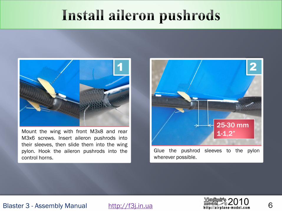
Tape the vertical stabilizer in place,then install the horizontal stabilizer onthe V-mount and slide them intoposition.
1
Put the stabilizer/V-mount back on thetail boom and align it with the wing.Glue the V-mount with thin CA.
3
Mark the position of V-mount onto thetail boom. To eliminate the gap, removethe V-mount and wind thin threadaround the boom.
25-10 mm0.2-0.4 inch
Install the vertical stabilizer as shown,ensure that it is perpendicular to thehorizontal stabilizer, and carefully glueit with thin CA.
4

Blaster 3 - Assembly Manual http://f3j.in.ua 8
Gather 2 pushrods with clevises andheat shrink tubes.
1
Slide heat shrink tube over the joint and drop CA inside the tube.
3
Glue clevises to one side of thepushrods with thin CA.
2
Glue sleeve pieces along the boom at40…50mm (1.5…2”) distance.
4
Blaster 3 - Assembly Manual http://f3j.in.ua 9
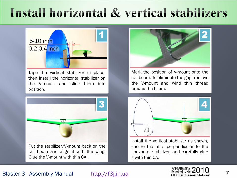
Sand the throwing peg as you find fit. Install the peg on the wing tip and glue
it with thin CA.
1 2

Blaster 3 - Assembly Manual http://f3j.in.ua 10
speedailerons 0˚
startailerons 1 mm up
normalailerons 1.5 mm down
thermalailerons 2.5 mm down
We recommend programming your transmitter for 4 flight modes
You can find additional information aboutdifferent flight modes at the following link onBlaster 3 page.
Make sure the C.G. is located at 80 mm (85…90 mm for experts) from the leading edge
at the wing root.Keep your TX and RX batteries charged!!!
In order not to damage the wing, launch the glider after a full revolution!!!

Please contact us, if you have trouble assembling Blaster 3 or if you have any questions:
http://f3j.in.ua
http://airplane-model.com
e-mail: [email protected]©