Embed Size (px)
Citation preview

Surface & Coatings Technology 205 (2011) 3175–3181
Contents lists available at ScienceDirect
Surface & Coatings Technology
j ourna l homepage: www.e lsev ie r.com/ locate /sur fcoat
Fabrication of various electroless Ni–P alloy/multiwalled carbon nanotube compositefilms on an acrylonitrile butadiene styrene resin
Susumu Arai a,⁎, Toshihiko Sato a, Morinobu Endo b
a Department of Chemistry and Material Engineering, Faculty of Engineering, Shinshu University, 4-17-1 Wakasato, Nagano-shi, Nagano 380-8553, Japanb Department of Electrical and Electronic Engineering, Faculty of Engineering, Shinshu University, 4-17-1 Wakasato, Nagano-shi, Nagano 380-8553, Japan
⁎ Corresponding author. Tel.: +81 26 269 5413; fax:E-mail address: [email protected] (S. Arai).
0257-8972/$ – see front matter © 2010 Elsevier B.V. Aldoi:10.1016/j.surfcoat.2010.11.030
a b s t r a c t
a r t i c l e i n f oArticle history:Received 14 September 2010Accepted in revised form 11 November 2010Available online 18 November 2010
Keywords:Ni―P alloyMultiwalled carbon nanotubeElectroless platingComposite filmAcrylonitrile butadiene styrene resin
Ni–P alloy/multiwalled carbon nanotube (MWCNT) composite films were fabricated on acrylonitrilebutadiene styrene (ABS) resin by electroless plating and their microstructures, adhesion strengths, andfriction properties were investigated. Various types of MWCNTs were used. In addition, various electrolessplating baths were prepared to form Ni–P alloy matrices with various phosphorus contents. To enhance theadhesion strength, the ABS resin substrate was subjected to roughening treatment. The microstructures of thecomposite films were examined by scanning electron microscopy and X-ray diffraction. Their adhesionstrengths were measured by tensile tests. The friction properties of the composite films were investigatedusing the ball-on-plate method. Ni–P alloy/MWCNT composite films containing various types of MWCNTs andwith Ni–P alloy matrices having various phosphorus contents were fabricated on the ABS resin substrates byelectroless deposition. The adhesion strength between the Ni–P alloy/MWCNT composite films and the ABSresin substrate was more than 1300 N cm−2. The Ni–P alloy/MWCNT composite films had considerably lowerfriction coefficients than the Ni–P alloy films. The friction coefficients of the composite films were significantlyaffected by the type of MWCNTs used.
+81 26 269 5432.
l rights reserved.
© 2010 Elsevier B.V. All rights reserved.
1. Introduction
Carbon nanotubes (CNTs) [1,2] have excellent mechanical char-acteristics including high tensile strengths and high elastic moduli.Therefore, research into practical applications of CNTs, including thepreparation of resin/CNT, ceramic/CNT, and metal/CNT composites,has been actively pursued. Recently, metal/CNT composites have beenfabricated by electrodeposition [3–8] and electroless deposition [8–16]. In previous studies of electroless CNT composite plating,electroless Ni–P alloy/multiwalled carbon nanotube (MWCNT) com-posite coatings were reported to have superior tribological properties[8–16]. In those studies, only 20-40-nm-diameter MWCNTs wereexamined. Furthermore, the effects of the size or species of MWCNTswere not reported. Electroless Ni–P alloy films are generally classifiedinto three categories based on their phosphorus content. Lowphosphorus films contain about 2–4 mass% phosphorus and have aface-centered-cubic nickel structure with relatively high crystal-linities. They are ferromagnetic and have been used to provideelectromagnetic shielding in electronic devices such as personalcomputers. Films with moderate phosphorus contents contain about6–10 mass% phosphorus and have semi-amorphous or amorphousstructures. They exhibit high wear and corrosion resistances and have
been most widely used as protective films for mechanical parts. Highphosphorus films contain 11–13 mass% phosphorus and have anamorphous structure. They have superior corrosion resistances andare nonmagnetic. They have thus been used as undercoatings for harddisk substrates. Therefore, the effects of the phosphorus content onthe microstructures and properties of the Ni–P alloy/MWCNTcomposite films are not only academically interesting but they arealso important for practical applications. However, few studies haveinvestigated the effects of phosphorus content on the properties ofelectroless Ni–P alloy/MWCNT composite films [17]. Furthermore,only metal substrates have been used in previous studies. Electrolessplating has the significant advantage that it can be used to fabricatefilms not only on conductive materials, such as metals, but also oninsulators, such as resins and ceramics. In this study, we fabricatedelectroless Ni–P alloy/MWCNT composite films containing varioustypes of MWCNTs and with Ni–P matrices with various phosphoruscontents on a resin substrate. We then evaluated their adhesionstrengths and friction properties.
2. Experimental
2.1. Chemicals
Commercially available vapor-grown MWCNTs, namely vapor-grown carbon fibers (VGCFs) and vapor-grown carbon nanofibers(VGNFs) (Showa Denko Co. Ltd.), and ILJINs (Iljin Nanotec Co. Ltd.)

3176 S. Arai et al. / Surface & Coatings Technology 205 (2011) 3175–3181
were used in the present study. Furthermore, cut VGCFs and cutVGNFs were prepared by mechanically cutting the VGCFs and VGNFsin a blender [18]. The VGCFs, VGNFs, and ILJINs had diameters of150 nm, 80 nm, and 15 nm, respectively. These MWCNTs were about15 μm long. The diameters of the cut VGCFs and cut VGNFs were thesame as those of the VGCFs and VGNFs (150 nm and 80 nm,respectively), whereas they were about 3–5 μm and 1–3 μm in length,respectively. These lengths were measured from micrographsobtained using a field-emission scanning electron microscope (FE-SEM; JEOL, JSM-7000 F). The VGCFs and VGNFs, (and hence also thecut VGCFs and cut VGNFs) are graphitized MWCNTs (heat treated at2800 °C in argon gas for 30 min) [19]. NiSO4∙6H2O, C6H5Na3O7,(NH4)2SO4, CrO3, Na2B4O7, Na3PO4, H2SO4, HCl, H2O2 (Wako PureChemical Industries, Ltd.), NaH2PO2∙H2O (Kanto Chemical Co., Ltd.),and trimethyl stearyl ammonium chloride (TMSAC, Tokyo ChemicalIndustry Co., Ltd.) were used in this study and were special gradereagents. Pure water from an electrodialysis water purifier(RFP343RA, Advantec MFS, Inc.) was used in all experiments. Anacrylonitrile butadiene styrene (ABS) resin plate (Mitsubishi Plastics,Inc.) was used as the substrate.
2.2. Roughening of the ABS resin substrates
Adhesion between metals and resins is generally poor. To enhancethe adhesion strength between the electroless Ni–P alloy/MWCNTcomposite films and the ABS resin substrate, the substrates weresubjected to a roughening treatment. The ABS resin substrates(3×3.3×1 cm) were degreased in alkaline solution (0.15 MNa2B4O7+0.12 M Na3PO4+1×10⁻⁴ M TMSAC) at 60 °C for 5 min.Next, the substrates were immersed in a chromic acid solution (4 MCrO3+4 M H2SO4) at 70 °C for 10 min to roughen the substratesurfaces. The substrates were then neutralized in a solution of 0.1 MHCl and 0.1 M H2O2 at 35 °C for 5 min.
2.3. Sensitization and activation of the ABS resin substrates
After the roughening process, the substrateswere immersed in 1 MHCl solution at room temperature for 1 min. Next, the substrates wereimmersed in a 4.4×10⁻² M SnCl2∙2H2O+0.12 MHCl solution at 35 °Cfor 5 min to absorb Sn2+ ions on the substrates (sensitization). Thesubstrates were then immersed in a 5.6×10⁻⁴ M PdCl2+0.12 M HClsolution at 35 °C for 5 min to form palladium catalytic nuclei on thesubstrates (activation).
2.4. Electroless Ni–P/CNT composite plating on the ABS resin substrate
After activation, the substrates were immersed in a 1 MHCl solutionand then placed in electroless plating baths to form Ni–P alloy/MWCNTcomposite films on the substrates. Three electroless plating baths wereused: 0.1 M NiSO4∙6H2O+0.5 M C6H5NaO7+0.2 M NaH2PO2∙H2O+(NH4)2SO4+1×10⁻⁴ MTMSAC+2 g dm−3MWCNTsolution (bath1),0.1 M NiSO4∙6H2O+0.2 M C6H5NaO7+0.2 M NaH2PO2∙H2O+(NH4)2SO4+1×10⁻⁴ M TMSAC+2 g dm−3 MWCNT solution (bath 2),and 0.16 M NiSO4∙6H2O+0.08 M C6H5NaO7+0.05 M NaH2PO2∙H2O+1×10⁻⁴ M TMSAC+2 g dm−3 MWCNT solution (bath 3) were used toform high phosphorus, moderate phosphorus, and low phosphorus Ni–Palloy matrices, respectively. The pH of all the baths was adjusted to 9.Electroless plating was performedwith stirrer agitation at 50 °C for baths1 and 3 and at 40 °C for bath 2.
2.5. Characterization of electroless Ni–P alloy/MWCNT composite films
The surface and cross-sectional morphologies of the compositefilms were observed using the FE-SEM. A cross-section polisher (JEOL,SM-09010) was used to prepare cross-sectional samples for observa-tions. Phase identification of the films was performed by X-ray
diffraction (XRD) using Cu Kα1 radiation (Shimadzu Seisakusho,XRD-6000). The phosphorus contents of the Ni–P alloy matrices weremeasured by electron probe microanalysis (EPMA; Shimadzu Seisa-kusho EPMA1610). The thicknesses of the composite films weremeasured from cross-sectional SEM images of the composite films.
2.6. Adhesion strength of electroless Ni–P alloy/MWCNT composite films
The adhesion strengths between the composite films and the ABSresin substrates were evaluated using a tensile adhesion tester(Phototechnica, Romulus). A stud pin with a thermosetting adhesiveon its end was attached to the sample film. The adhesive was thenheated to promote heat curing, resulting in strong adhesion betweenthe stud pin and the sample film. Heating is generally performed at150 °C for 60 min to achieve maximum adhesion strength betweenthe stud pin and the sample film. However, since the ABS resinsubstrate deformed at 150 °C, heating was performed at 100 °C for180 min in this study. Consequently, the adhesion strength betweenthe stud pin and the sample film was lower than the maximumadhesion strength. The adhesion test was conducted by pulling thestud pin from the sample film in the perpendicular direction. The force(adhesion force) at which the stud pin separated from the sample filmwas measured and divided by the contact area to give the adhesionstrength. If the adhesion force between the film and the substrate islower than that between the stud pin and the sample film, exfoliationoccurs between the film and the substrate (film–substrate exfoliationmode), and the measured force represents the adhesion forcebetween the film and the substrate. However, if the adhesion forcebetween the film and the substrate is higher than that between thestud pin and the film, exfoliation occurs between the stud pin and thefilm (stud pin–film exfoliationmode). In this study, the adhesion forcebetween the film and the substrate was found to be greater than thatbetween the stud pin and the film.
2.7. Friction properties of electroless Ni–P alloy/MWCNT composite films
The friction coefficients of the composite films were measuredusing a ball-on-plate type reciprocating friction tester (Nissho ElectricWorks, MMS-2419). An alumina ball (6 mm in diameter, Hv=1500)was used as the counter surface. The reciprocating friction stroke was4 mm and the tests were conducted under a normal load of 2 N. Theaverage sliding speed was 0.5 mm s−1 and the number of cycles was50. All measurements were performed under ambient conditionswithout any lubricants. The friction coefficient was measuredcontinuously during the tests using a load cell.
3. Results and discussion
Fig. 1 shows surface SEM images of the ABS resin substrate beforeand after the surface roughening treatment. The roughened substratehas many hollows on its surface (Fig. 1(b)). These hollows wereformed by selective dissolution of butadiene in the ABS resin. Thesehollows impart a large surface area. Furthermore, if the hollows havecomplex shapes and are filled with the plating film, then the platingfilm becomes hooked in the hollows, making it difficult to remove andresulting in high adhesion (this is known as the anchor effect).
Fig. 2 shows the growing process of a Ni–P alloy/MWCNTcomposite film on a roughened ABS substrate. The MWCNTs andelectroless plating bath used were the VGCFs and the high-phosphorus-content bath (bath 1), respectively. At an early stage,the hollows on the substrate are filled with the deposited Ni–P alloy(Fig. 2(b)). After 10 min, the hollows are almost completely filledand some VGCFs are incorporated in the Ni–P alloy matrix (Fig. 2(c)).The Ni–P alloy/VGCF composite film then grows autocatalytically(Fig. 2(d)). Other Ni–P alloy/MWCNT composite films grew in asimilar manner on the roughened ABS resin substrates.

Fig. 1. Surface SEM images of an ABS resin substrate (a) before and (b) after roughening treatment.
3177S. Arai et al. / Surface & Coatings Technology 205 (2011) 3175–3181
Fig. 3 shows surface SEM images of the Ni–P alloy/MWCNTcomposite films with various MWCNTs fabricated from the moderate-phosphorus-content bath (bath 2). The deposition time was 90 min.For comparison, a Ni–P alloy film without MWCNTs is also shown(Fig. 3(a)). The SEM image of the Ni–P alloy/ILJIN composite film(Fig. 3(f)) has a higher magnification than the other SEM images,because the ILJINswere very thin so that they could not be observed atthe same magnification as the other CNTs. The films were about 3 μmthick, except for the Ni–P alloy/ILJIN composite film, which was about4 μm thick. The Ni–P alloy matrix of all these films were found to havephosphorus contents of about 8 mass%, which lies in the phosphoruscontent range of 6–10 mass%. Therefore, these composite films haveNi–P alloy matrices with moderate phosphorus contents (seeIntroduction). These moderate-phosphorus-content Ni–P alloy/MWCNT composite films are relatively smooth, except for the Ni–Palloy/ILJIN composite film. A bumpy morphology consisting of sphericaldeposits with 2–3 μm diameters was observed on the Ni–P alloy/ILJINcomposite film. All the different MWCNTs are homogeneouslydistributed over the film surfaces, with no significant aggregations.
Fig. 2. SEM images showing growth of electroless Ni–P alloy/VGCF composite films on an AB(d) after 30 min. The plating bath is the high-phosphorus-content bath (bath 1).
The Ni–P alloy/MWCNT composite films fabricated from the high-phosphorus-content bath (bath 1) have almost the same surfacemorphologies as the moderate-phosphorus-content Ni–P alloy/MWCNT composite films. The phosphorus contents in the Ni–P alloymatrices of those composite films were found to be about 12 mass%,which lies in the phosphorus content range 11–13 mass%. Therefore,these composite films have Ni–P alloy matrices with high phosphoruscontents (see Introduction). Thus, high-phosphorus-content Ni–Palloy/MWCNT composite films and moderate-phosphorus-contentNi–P alloy/MWCNT composite films could be successfully fabricatedon the ABS resin substrates using all the different types of MWCNTsused in this study.
On the other hand, only the Ni–P alloy/ILJIN composite film couldbe fabricated from the low-phosphorus-content bath (bath 3). TheVGCFs, the cut VGCFs, the VGNFs, and the cut VGNFs were notincorporated in the Ni–P alloy matrix. Comparing the composition ofthe low phosphorus content bath with those of the high and moderatephosphorus content baths, it was noted that no (NH4)2SO4 is present inthe low phosphorus content bath. Therefore, the existence of (NH4)2SO4
S resin substrate: (a) before electroless deposition, (b) after 1 min, (c) after 10 min, and
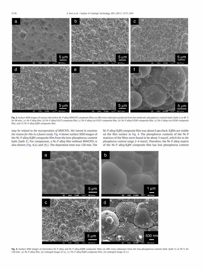
Fig. 3. Surface SEM images of various electroless Ni–P alloy/MWCNT composite films on ABS resin substrates produced from themoderate-phosphorus-content bath (bath 2) at 40 °Cfor 90 min: (a) Ni–P alloy film, (b) Ni–P alloy/VGCF composite film, (c) Ni–P alloy/cut VGCF composite film, (d) Ni–P alloy/VGNF composite film, (e) Ni–P alloy/cut VGNF compositefilm, and (f) Ni–P alloy/ILJIN composite film.
3178 S. Arai et al. / Surface & Coatings Technology 205 (2011) 3175–3181
may be related to the incorporation of MWCNTs. We intend to examinethe reason for this in a future study. Fig. 4 shows surface SEM images ofthe Ni–P alloy/ILJIN composite film from the low-phosphorus-contentbath (bath 3). For comparison, a Ni–P alloy film without MWCNTs isalso shown (Fig. 4(a) and (b)). The deposition time was 120 min. The
Fig. 4. Surface SEM images of electroless Ni–P alloy and Ni–P alloy/ILJIM composite films120 min: (a) Ni–P alloy film, (b) enlarged image of (a), (c) Ni–P alloy/ILJIN composite film
Ni–P alloy/ILJIN composite filmwas about 6 μm thick. ILJINs are visibleon the film surface in Fig. 4. The phosphorus contents of the Ni–Pmatrices of the films were found to be about 3 mass%,which lies in thephosphorus content range 2–4 mass%. Therefore, the Ni–P alloy matrixof the Ni–P alloy/ILJIN composite film has low phosphorus content
on ABS resin substrates from the low-phosphorus-content bath (bath 3) at 50 °C for, (d) enlarged image of (c).

30 40 50 60
(a)
(b)
(c)
2 θ / degree
Inte
nsity
/ a.
u.Nickel
Fig. 5. XRD patterns of various composite films on ABS resin substrates: (a) high-phosphorus-content Ni–P alloy/VGCF composite film, (b) moderate-phosphorus-content Ni–P alloy/ILJIN composite film, and (c) low-phosphorus-content Ni–P alloy/ILJIN composite film.
0
500
1000
1500
2000
2500
3000
3500
Fig. 7. Measured adhesion strengths of various moderate-phosphorus-content Ni–Palloy/MWCNT composite films.
3179S. Arai et al. / Surface & Coatings Technology 205 (2011) 3175–3181
(see Introduction). Thus, a low-phosphorus-content Ni–P alloy/MWCNT composite film could be fabricated on ABS resin substratesusing the ILJINs.
Fig. 5(a), (b), and (c) respectively show representative XRDpatterns of the high-phosphorus-content, moderate-phosphorus-content, and low-phosphorus-content electroless Ni–P alloy/MWCNT composite films on the ABS resin substrates. The XRDpatterns contain no diffraction peaks assigned to MWCNTs. Thediffraction peaks of the MWCNTs are considered to have very weakintensities. A broad peak assigned to face-centered-cubic nickel wasobserved in the XRD pattern of the high-phosphorus-content Ni–Palloy/VGCF composite film (Fig. 5(a)). This indicates that the Ni–Palloy matrices of the high-phosphorus-content Ni–P alloy/MWCNTcomposite films have an amorphous structure. A broad peak assignedto face-centered-cubic nickel was also observed in the XRD pattern ofthe moderate-phosphorus-content Ni–P alloy/ILJIN composite film(Fig. 5(b)). The peak is a little sharper than that of the high-phosphorus-content composite film. This indicates that the Ni–P alloymatrices of the moderate-phosphorus-content Ni–P alloy/MWCNTcomposite films have an amorphous or a semi-crystalline structure.Relatively sharp peaks assigned to face-centered-cubic nickel wereobserved in the XRD pattern of the low-phosphorus-content Ni–Palloy/ILJIN composite film (Fig. 5(c)). This indicates that the Ni–P alloy
Fig. 6. Cross-sectional SEM images of (a) electroless Ni–P alloy and (b) Ni–P alloy/VGCF compat 40 °C for 90 min.
matrices of the low-phosphorus-content Ni–P alloy/ILJIN compositefilm have relatively high crystallinities.
Fig. 6 shows representative cross-sectional SEM images of the films(Fig. 6(a): a moderate-phosphorus-content Ni–P alloy film; Fig. 6(b):a moderate phosphorus-content Ni–P alloy/VGCF composite film).The black regions in the composite film are cross sections of the VGCFs(Fig. 6(b)). The hollows on the ABS resin substrate were completelyfilled with the Ni–P alloy/VGCF composite film, just as they were forthe Ni–P alloy films. Other Ni–P alloy/MWCNT composite films hadthe same boundaries with the ABS resin substrates as the moderate-phosphorus-content Ni–P alloy/VGCF composite film. Therefore, theNi–P alloy/MWCNT composite films are expected to exhibit highadhesion strengths due to the anchor effect.
Fig. 7 shows the results of measuring the adhesion strengthbetween the moderate-phosphorus-content Ni–P alloy/MWCNTcomposite films and the ABS resin substrate. Based on observationof the exfoliated area, the exfoliation mode was found to be the studpin–film exfoliation mode for all samples. Therefore, the adhesionstrengths of all the samples are higher than the values shown in Fig. 7(2000–3000 N cm−2). The exfoliation mode of the high-phosphorus-content Ni–P alloy/MWCNT composite films and the low-phosphorus-content Ni–P alloy/ILJIN composite film were also the stud pin–filmexfoliation mode, and the measurement values were about 1300–2800 N cm−2 for the high-phosphorus-content Ni–P alloy/MWCNTcomposite films and 2200 N cm−2 for the low-phosphorus-contentNi–P alloy/ILJIN composite film. Therefore, the adhesion strengths ofthe high-phosphorus-content Ni–P alloy/MWCNT composite films
osite films on ABS resin substrates for the moderate-phosphorus-content bath (bath 2)

Fric
tion
coef
ficie
nt
0
0.1
0.2
0.3
0.4
0.5
High phosphorus content
Moderate phosphorus content
Low phosphorus content
Fig. 8. Comparison of friction coefficients of various Ni–P alloy/MWCNT compositefilms. The friction coefficients are the values at 50 cycles.
3180 S. Arai et al. / Surface & Coatings Technology 205 (2011) 3175–3181
and the low-phosphorus-content Ni–P alloy/ILJIN composite film aregreater than the measured values. No substantial difference wasfound between the measured values for the Ni–P alloy films and forthose for the Ni–P alloy/MWCNT composite films. Thus, the adhesionstrengths between the composite films and the ABS resin substratewere at least greater than 1300 N cm−2. The adhesion strengths areexpected to originate from the anchor effect.
Fig. 8 shows the friction coefficients of the Ni–P alloy/MWCNTcomposite films. For comparison, the friction coefficients of the Ni–Palloy films are also shown. The films are 3–6 μm thick, except for the
Fig. 9. SEM images of worn surface of the moderate-phosphorus-content Ni–P alloy/MWCN(c) Ni–P alloy/cut-VGCF composite, (d) Ni–P alloy/VGNF composite, (e) Ni–P alloy/cut-VGN
Ni–P alloy/ILJIN composite films, which are 4–10 μm thick. The frictioncoefficients are the values at 50 cycles. No exfoliation of the film fromthe ABS resin substrate was observed for any sample during thefriction test. This demonstrates that there is good adhesion betweenthe composite films and the ABS resin substrates.
Fig. 9 shows SEM images of worn surfaces of the moderate-phosphorus-content Ni–P alloy/MWCNT composite films after the frictiontest. The scratches are not very deep and unscratched regions are visibleon the surface in places. This indicates that the scratches did not reach theABS resin substrates. This was also true for the high-phosphorus-contentand low-phosphorus-content Ni–P alloy/MWCNT composite films. TheNi–P alloy/MWCNT composite films have substantially lower frictioncoefficients than the Ni–P alloy films in spite of the differentphosphorus content of the Ni–P alloy matrix. This reduction in thefriction coefficient might be due to the intrinsic lubricity of theMWCNTs. Dickrell et al. reported that the friction coefficients ofvertically and transversely aligned MWCNTs are 0.795 and 0.090,respectively; they measured them under ambient conditions using aborosilicate glass pin as the counter surface [20]. Therefore, thetransversely aligned MWCNTs on the composite film surface mightfunction as a solid lubricant [21]. The Ni–P alloy/ILJIN composite filmsshowed the highest friction coefficients in the Ni–P alloy/MWCNTcomposite films regardless of the phosphorus content of the Ni–Palloy matrix. Since the VGCFs, the cut VGCFs, the VGNFs, and the cutVGNFs are graphitized MWCNTs, the crystallinity of the MWCNTsmight be related to the friction coefficient of the composite films. Noobvious difference was observed between the friction coefficients ofthe VGCFs, the cut VGCFS, the VGNFs, and the cut VGNFs. Therefore,the different lengths and diameters of the MWCNTs used in this studydid not appreciably affect the friction coefficients of the compositefilms. Strictly speaking, the differences in the number of the MWCNTson the film surface, the film thicknesses, and the surface roughnessesof the composite films should be taken into account; we intend toinvestigate this in future studies.
T composite films after the friction test: (a) Ni–P alloy, (b) Ni–P alloy/VGCF composite,F composite, and (f) Ni–P alloy/ILJIN composite film.

3181S. Arai et al. / Surface & Coatings Technology 205 (2011) 3175–3181
4. Conclusion
Electroless Ni–P alloy/MWCNT composite films containing varioustypes of MWCNTs and having Ni–P alloy matrices with variousphosphorus contents were fabricated on ABS resin substrates. Theadhesion strengths of the composite films were at least greater than1300 N cm−2 due to the anchor effect. The friction coefficients of thecomposite films were obviously lower than those of the Ni–P alloyfilms. Thus, the electroless CNT composite plating technique used inthis study can be used to produce metal/CNT composite coatings onresins and can impart various properties of CNTs or metal/CNTcomposites to the resins. This technique is expected to be effective forother insulators such as ceramics.
Acknowledgements
This research was supported by Regional Innovation ClusterProgram of Nagano, granted by MEXT, Japan.
References
[1] A. Oberlin, M. Endo, T. Koyama, J. Cryst. Growth 32 (1976) 335.[2] S. Iijima, T. Ichihashi, Nature 363 (1993) 603.
[3] X.H. Chen, J.C. Peng, X.Q. Li, F.M. Deng, J.X. Wang, W.Z. Li, J. Mater. Sci. Lett. 20(2001) 2057.
[4] J. Tan, T. Yu, B. Xu, Q. Yao, Tribol. Lett. 21 (2006) 107.[5] B.M. Praveen, T.V. Venkatesha, Y. Arthoba Naik, K. Prashantha, Surf. Coat. Techol.
201 (2007) 5836.[6] S. Arai, M. Endo, Electrochem. Commun. 5 (2003) 797.[7] S. Arai, M. Endo, N. Kaneko, Carbon 42 (2004) 641.[8] B.C. Satishkumar, E.M. Vogl, A. Govindaraj, C.N.R. Rao, J. Phys. D Appl. Phys. 29
(1996) 3173.[9] S. Arai, T. Saito, M. Endo, J. Electrochem. Soc. 157 (2010) D147.
[10] W.X. Chen, J.P. Tu, H.Y. Gan, Z.D. Xu, Q.G. Wang, J.Y. Lee, Z.L. Liu, X.B. Zhang, Surf.Coat. Tech. 160 (2002) 68.
[11] X.H. Chen, G. Zhang, C.S. Chen, L.P. Zhou, S.L. Li, X.Q. Li, Adv. Eng. Mater. 5 (2003)514.
[12] W.X. Chen, J.P. Tu, Z.D. Xu, W.L. Chen, X.B. Zhang, D.H. Cheng, Mater. Lett. 57(2003) 1256.
[13] W.X. Chen, J.P. Tu, L.Y. Wang, H.Y. Gan, Z.D. Xu, X.B. Zhang, Carbon 41 (2003) 215.[14] L.Y. Wang, J.P. Tu, X.W. Chen, Y.C. Wang, X.K. Liu, C. Olk, D.H. Chang, X.B. Zhang,
Wear 252 (2003) 1289.[15] Z. Yang, H. Xu, Y.L. Shi, M.K. Li, Y. Huang, H.L. Li, Mater. Res. Bull. 40 (2005) 1001.[16] X.H. Chen, C.S. Chen, H.N. Xiao, H.B. Liu, L.P. Zhou, S.L. Li, G. Zhang, Tribol. Int. 39
(2006) 22.[17] S. Arai, T. Sato, M. Endo, J. Electrochem. Soc. 157 (2010) D570.[18] K.C. Park, M. Fujishige, K. Takeuchi, S. Arai, S. Morimoto, M. Endo, J. Phys. Chem.
Solids 69 (2008) 2481.[19] M. Endo, CHEMTEC 18 (1988) 568.[20] P.L. Dickrell, S.B. Sinnott, D.W. Hahn, N.R. Raravikar, L.S. Schadler, P.M. Ajayan, W.G.
Sawyer, Tribol. Lett. 28 (2005) 59.[21] S. Arai, A. Fujimori, M. Murai, M. Endo, Mater. Lett. 62 (2008) 3545.