Embed Size (px)
Citation preview
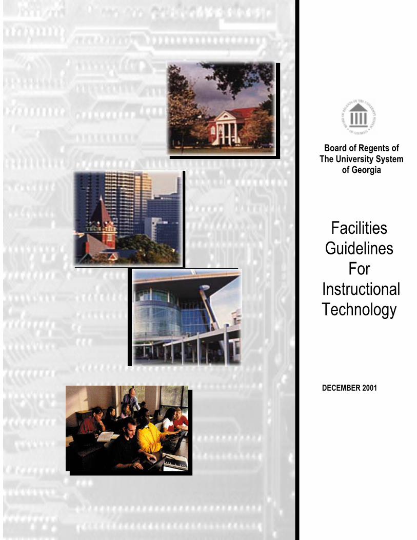
DECEMBER 2001
Facilities Guidelines
For Instructional Technology
Board of Regents of The University System
of Georgia
BOARD OF REGENTS OF THE UNIVERSITY SYSTEM OF GEORGIA
1 Facilities Guidel ines for Instruct ional Technology FINAL
Table of Contents PREFACE Introduction Background and Scope Charge to the Task Force Objectives Participants 1. GENERAL CONSIDERATIONS
Integration Goals
2. PROCESS Set Up Participants Topics
Work Flow
3. GENERAL CRITERIA
Seating Sightlines Lighting Sound Quality of Finishes HVAC Telecommunication Miscellaneous
4. ROOM DESCRIPTIONS Classrooms
Standard Classroom Advanced Classroom High Technology classroom
Auditoria/Large Lecture Hall Standard Seminar High Technology Seminar
Laboratories Wet Laboratories Dry Laboratories Computer Lab – Instructional
BOARD OF REGENTS OF THE UNIVERSITY SYSTEM OF GEORGIA
2 Facilities Guidel ines for Instruct ional Technology FINAL
Computer Lab – Open (Self-instruction) Offices
Administrative Offices Faculty Administrative Suites
Faculty Offices Informal Study
Informal Collaborative Areas 5. GLOSSARY ABBREVIATED APPENDIX (This is a separate document available, for downloading, off the ‘web based’ version of these guidelines. It contains ‘rough drafts’ of data and specifications provided by various sub committees of the Task Force)
BOARD OF REGENTS OF THE UNIVERSITY SYSTEM OF GEORGIA
3 Facilities Guidel ines for Instruct ional Technology FINAL
PREFACE This section provides an overview of the background information used as the foundation for these guidelines. It also summarizes the intent and content of this document. The section contains the following subsections:
• Introduction • Background and Scope • Charge to the Task Force • Objectives • Participants
BOARD OF REGENTS OF THE UNIVERSITY SYSTEM OF GEORGIA
4 Facilities Guidel ines for Instruct ional Technology FINAL
PREFACE
Introduction In October 2000, a task force was formed to study the implications of electronic technology on the construction of facilities for the University System of Georgia (USG). A key driving force behind this initiative was the desire to develop and implement a well-conceived and consistent concept for how technology requirements can best be accommodated in designing new and renovated facilities. Early input from faculty user groups and campus technology staff is critical in constructing facilities that accommodate instructional technology successfully. This concept will have far reaching benefits for all.
Modern methods of teaching and learning rely, in varying
degrees, on electronic technology as a means to support the curriculum. Instructional technology must, therefore, be capable of responding to the various educational support needs within the buildings and facilities that compose the physical campus. This publication outlines the minimum technology considerations needed for learning spaces created in the USG.
Background & Scope During the past decade, rapid changes in the use of technology have required that all USG facilities, new and existing, provide an environment that is flexible and adaptable to these rapid changes. This common desire for flexibility is further driven by the fact that “consistency” within all institutions must be balanced against the need for some capital projects to be “customized”. Customization is driven by a need to recognize certain unique characteristics of instructional methodology used at various campuses. These likely derive from each institution’s mission, location, size and staffing needs. Thus, the Facilities Guidelines for Instructional Technology Task Force set about to understand the relationship between technology, the delivery of instruction through the system and its impact on facilities. Specifically, it set to provide guidelines for the minimum technology needed in key categories of instructional and instructional support spaces, built or renovated, within the University System. The guidelines provide descriptions and, as a separate APPENDIX, specifications for telecommunications wiring, Cable TV (CATV) connectivity, satellite connectivity; intra-building and inner-building connectivity, lighting, wireless, audio-visual, and telephone. Throughout the Task Force’s discussions, the 2000 Pre-Planning Guidelines were used
BOARD OF REGENTS OF THE UNIVERSITY SYSTEM OF GEORGIA
5 Facilities Guidel ines for Instruct ional Technology FINAL
as a model and a guide. Within this context, it should be noted that these guidelines are written using the concept of ‘wired’ (partial or full) technology as a baseline. Further advances in ‘wireless’ and other aspects of instructional technology that are not part of these guidelines should be considered as options and enhancements to this document. Adopting these is possible, provided all aspects of the implementation: planning, design and systems integration, cost, maintenance and operations are addressed. The scope of this document is also to outline a process for developing, detailing and maintaining the technology infrastructure of a building. This process is detailed in forthcoming sections. Broadly speaking, it should include:
• The participation on the part of the institution’s Design/Planning Office and its Instructional Technology Office.
• The distribution and use of these guidelines as criteria for setting up and developing the technology requirements of a capital project. It should serve as a key resource for the staff and the consultants.
• The incorporation of Instructional Technology as a topic to be addressed during all formal design reviews set through the Board of Regent’s process.
Currently, the scope of a capital project is determined at the individual campus level. Program support features (e.g., number, type and size of rooms, spatial adjacencies, and electronic support requirements) are identified by the building’s prospective users and extrapolated into a building concept by the design architect. Both cost and quality of instructional technology are, thus, directly attributable to the program developed by the campus to support the identified educational purpose. This process results in a number of issues that require consideration.
• Depending on the mission of the institution, similar programs at different campuses can generate instructional support needs that have vastly different requirements and, thus, greatly affect a project’s cost, quality and scope.
• Programming a building to support a specific
purpose may limit the capability of the instructional
Issues
BOARD OF REGENTS OF THE UNIVERSITY SYSTEM OF GEORGIA
6 Facilities Guidel ines for Instruct ional Technology FINAL
technology to serve other current or future purposes.
• The level and sophistication of the user group will
vary from campus to campus and will, thus, lead to variations in the installation of divergent instructional technology capability at the campuses.
• When a building is programmed to support a
specific use, it is likely that the capability of adapting the building for future alternate uses may be cost prohibitive.
Charge The task force was charged to review these and other
issues associated with making physical provision for instructional technology in the USG’s facilities and to recommend standards or guidelines that could serve as a baseline for instructional and instructional support spaces. There are many benefits to be accrued from the establishment of a set of standards or guidelines for the instructional technology equipment (hardware and intra-building connectivity). These benefits include:
• With technology playing such an important role, to ensure that newly constructed or renovated facilities are better able to support instruction now and in the future.
• Reduction in the time required to complete a building’s programming and design;
• Well thought out and developed features that support the future adaptability of a building and its potential to accommodate alternative programs. These features could be consistent within the system’s institutions;
• A reduction in the maintenance requirements by providing a common list of equipment and system criteria.
• Ease of use by faculty, staff and students. Users will be able to anticipate the instructional technology capability of most rooms.
The Task Force was further charged to consider the differences between the campuses in terms of mission, location, size, and staffing requirements to assure that the baseline standards/guidelines provide reasonable access capabilities to all System institutions. In this regard, the Task Force considered, in broad terms, the
BOARD OF REGENTS OF THE UNIVERSITY SYSTEM OF GEORGIA
7 Facilities Guidel ines for Instruct ional Technology FINAL
first-time costs associated with the installation of the technology, associated maintenance and upkeep costs, and importantly, flexibility to respond to future requirements. These guidelines should accommodate the academic objectives of the USG Board of Regents which include: ”… technology to advance educational purposes, including instructional technology, student support services and distance education”. “… providing and maintaining superior facilities, funded by innovative mechanisms which increase the speed with which they are usable”.
The intended outcome is a baseline for facilities guidelines that provide for electronic technology in all USG buildings. The guidelines will form the minimum standards for various room types, together with a suggested room diagram. They include the development of standards for the following types of spaces: • Classrooms • Laboratories • Offices • Informal Study Rooms The Task Force met and considered the many issues within its charge, as determined by the Chair of the Task Force, President Clifford M. Brock. As a part of its investigation and deliberation, the Task Force reviewed similar work previously conducted or under way by other institutions of higher learning and private industry. The Task Force invited guest speakers to inform the members regarding technology standards and related matters that are in use elsewhere.
Notes The charge to this Task Force did not include the
University Library. Libraries have special and particular needs for computer/data/electronic support and, as such, warrant individual attention. However, libraries include features that are within this Task Force’s charge, i.e., informal student collaborative areas. The purpose of this Task Force was to focus on issues dealing with the physical features necessary to provide electronic technology within buildings. Issues dealing with instructional pedagogy, software, distributed or
Objectives
BOARD OF REGENTS OF THE UNIVERSITY SYSTEM OF GEORGIA
8 Facilities Guidel ines for Instruct ional Technology FINAL
distance learning, etc. are more properly addressed elsewhere, including the Master Plan for Information and Instructional Technology adopted by the Board of Regents on 8/8/00. It is important to refer to the date of publication and subsequent updates of these guidelines as a reference point for its ‘baseline’ approach. This baseline should be evaluated against the ‘current’ applications and options for enhancements may need to be considered. It is understood that fast changes will continue to occur in the area of instructional technology.
Participants Dr. Clifford Brock President Bainbridge College Mr. John Scoville Executive Director for Enterprise Infrastructure Services Office of Information & Technology Mr. David Sims Director, Plant Operations Macon State College Mr. Donald P. Alexander, P.E., RCDD Institute Engineer Georgia Institute of Technology Mr. Thomas Archibald Assistant to President for Information Technology Valdosta State University Mr. Kris Turnbull Director, Continuing Education Center for Computer Technologies Kennesaw State University Mr. James Wolfgang Chief Information Officer Georgia College & State University Ms. Gita Hendessi Director of Planning Office of Facilities, Board of Regents
The task force would like to gratefully acknowledge the efforts of the chairperson, Dr. Clifford Brock, Dr. Karen Fritz, Dr. Rob Gingras and Mr. Cary Bohannon in preparing the many drafts of this report.
BOARD OF REGENTS OF THE UNIVERSITY SYSTEM OF GEORGIA
9 Facilities Guidel ines for Instruct ional Technology FINAL
GENERAL CONSIDERATIONS
This section explores general topics that must be considered when providing an environment that supports the needs of instructional technology. The section contains the following subsections:
• Integration with other planning efforts • Goals
BOARD OF REGENTS OF THE UNIVERSITY SYSTEM OF GEORGIA
10 Facilities Guidel ines for Instruct ional Technology FINAL
BLANK
BOARD OF REGENTS OF THE UNIVERSITY SYSTEM OF GEORGIA
11 Facilities Guidel ines for Instruct ional Technology FINAL
GENERAL CONSIDERATIONS This section will provide an overview of the issues that should be considered when incorporating modern technologies to support programmatic requirements (instruction, student support, research, etc) and allow for the incorporation of evolving technologies in a cost-effective manner. It highlights the considerations that should be addressed in order to realize the goals of the Task Force guide. There are profound considerations to the use of Internet and computers. The information explosion of the last several decades has made the Internet one of the instruments that must be integrated into the instructional delivery system of an institution. Through this, and other instruments, the educator can expand the topics and terms to be explored by a student. As a result, we find ourselves expanding the definition of literacy to include varieties of media, some of which are evolving, others which have yet to be invented. Many colleges and universities have recognized the impact that computer technology, the Internet, and multimedia forms of learning have had on traditional classroom delivery methods for years. As with most capital expenditures, planning for new campus facilities should be based on pedagogical and programmatic requirements, and technology must be included in all facilities planning. Given that buildings are intended to have at a minimum, a 30-year life span, considering the impact of technologies for the future of learning on campus is a critical step in planning 21st century facilities. All technology planning efforts conducted by an institution must take into consideration the criteria and process set under various pre-planning resources. This includes the system’s Guidelines for Physical Master Planning, Master Plan for Information and Instructional Technology and the campus’ own Campus Technology Master Plan. How these are integrated into the use of these guidelines is outlined in the Process Section of this document. Specific to technology considerations, the 2000 Pre-Planning Guidelines offer key guidance. These guidelines establish that technology requirements be considered during early pre-planning and programming. These
Integration

BOARD OF REGENTS OF THE UNIVERSITY SYSTEM OF GEORGIA
12 Facilities Guidel ines for Instruct ional Technology FINAL
requirements should be balanced against the most current applications. They should be monitored and validated through all phases of implementation. Technology planning efforts should also include many participants. Key participants are the instructional technology staff of the institution. Their involvement should be constant throughout the process. The participants and process is described at the end of this section The planning challenge is to provide a learning environment in which the values inherent in traditional instruction continue to be fostered, as distance and other learning technologies enable new opportunities and universal access. The following planning Goals should be addressed:
• Flexibility • Accessibility • Life Cycle • Cost Benefit
Flexibility, so students can access instructional courses via alternative modes of delivery. This includes addressing “adaptability” and “scalability” of the systems used. By definition, “scalability” is how well a solution to some problem will work when the size of the project increases. “Adaptability” is defined as responsiveness to change, ideally without compromising the quality of a space, system or network during this evolutionary process.
Scalability calls for an infrastructure for satellite communications, digital transmission, distributed learning, and hardware that is compatible with industry standards. This infrastructure should have sufficient capacity (bandwidth) and the ability to reconfigure the rooms, while designing new infrastructure including appropriate cabling (twisted pairs, fibers, etc.), sufficient telecommunications/data closet space, and appropriate security. Technological accessibility and campus connectivity to various sites, i.e., spaces should be designed to be flexible, reconfigurable, and multi-purpose. Users must be able to easily ‘enter’ or access the various forms of information available within the system.
Goals
BOARD OF REGENTS OF THE UNIVERSITY SYSTEM OF GEORGIA
13 Facilities Guidel ines for Instruct ional Technology FINAL
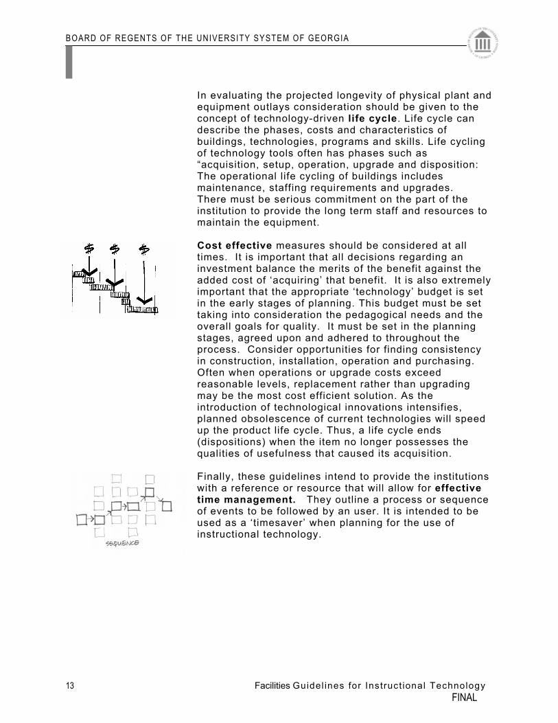
In evaluating the projected longevity of physical plant and equipment outlays consideration should be given to the concept of technology-driven life cycle. Life cycle can describe the phases, costs and characteristics of buildings, technologies, programs and skills. Life cycling of technology tools often has phases such as “acquisition, setup, operation, upgrade and disposition: The operational life cycling of buildings includes maintenance, staffing requirements and upgrades. There must be serious commitment on the part of the institution to provide the long term staff and resources to maintain the equipment. Cost effective measures should be considered at all times. It is important that all decisions regarding an investment balance the merits of the benefit against the added cost of ‘acquiring’ that benefit. It is also extremely important that the appropriate ‘technology’ budget is set in the early stages of planning. This budget must be set taking into consideration the pedagogical needs and the overall goals for quality. It must be set in the planning stages, agreed upon and adhered to throughout the process. Consider opportunities for finding consistency in construction, installation, operation and purchasing. Often when operations or upgrade costs exceed reasonable levels, replacement rather than upgrading may be the most cost efficient solution. As the introduction of technological innovations intensifies, planned obsolescence of current technologies will speed up the product life cycle. Thus, a life cycle ends (dispositions) when the item no longer possesses the qualities of usefulness that caused its acquisition. Finally, these guidelines intend to provide the institutions with a reference or resource that will allow for effective time management. They outline a process or sequence of events to be followed by an user. It is intended to be used as a ‘timesaver’ when planning for the use of instructional technology.
BOARD OF REGENTS OF THE UNIVERSITY SYSTEM OF GEORGIA
14 Facilities Guidel ines for Instruct ional Technology FINAL
BLANK
BOARD OF REGENTS OF THE UNIVERSITY SYSTEM OF GEORGIA
15 Facilities Guidel ines for Instruct ional Technology FINAL
This section outlines a general process for reviewing the technology needs for a capital project. Content of this section is:
• Set Up • Participants • Topics • Work Flow
PROCESS
BOARD OF REGENTS OF THE UNIVERSITY SYSTEM OF GEORGIA
16 Facilities Guidel ines for Instruct ional Technology FINAL
BLANK
BOARD OF REGENTS OF THE UNIVERSITY SYSTEM OF GEORGIA
17 Facilities Guidel ines for Instruct ional Technology FINAL
Set Up The design and construction of a facility will require retaining consultants. The consulting team will be contracted following the standard format set by the University System of Georgia Board of Regents. The USG office of facilities Building Project Procedure includes an outline of this process.
Participants from each one of these areas should be
considered: Institution:
Office of the President representative (s) Office of Business representative (s), including one for Physical Plant Office of Instructional Technology Office of Academic Affairs representative (s) Student (s) Faculty (s) Staff (s) BoR: Office of Facilities Other It is suggested that the participants be organized into two basic groups: Core User Group This is a small group of people charged with the authority to provide overall direction during the process. They are to review the progress at key decision points, make decisions, and keep the project on track. Extended User Group This group can be much larger. Its make-up is much broader and includes staff, faculty and students. These people bring information on various areas of specific interest, whether an instructional unit, the physical plant or the users. A third group may be considered if circumstances merit extensive involvement of neighboring or external constituents. A liaison will be identified as the point of contact and coordinator of the process.
Set Up
BOARD OF REGENTS OF THE UNIVERSITY SYSTEM OF GEORGIA
18 Facilities Guidel ines for Instruct ional Technology FINAL
Internal It is extremely important to set the stage for a physical
improvement project. In doing so, each institution must identify key participants and initiate some pre-planning tasks to outline the scope.
The commitment to providing the ‘best’ in information
technology capabilities as part of the project must be supported by the college or university leadership. Without the support of the President and senior administration, efforts will be met with resistance and, in turn, frustration. Dialogue with this group must establish the direction and nature of future strategies, engaging them in the process so that they develop a sense of ownership. Site-based leadership provides day-to-day support to the teaching staff. This group includes the President, VP-Business & Finance, Plant Operations, VP-Information Technology and possibly a leadership group representing the faculty. All individuals must be meaningfully engaged in defining and implementing the project. Those who understand the institution’s information and technology systems must be active participants in this process. The faculty must be made aware that technology planning and design should respond to current and projected teaching and learning strategies. Many faculties may be attempting to incorporate new strategies but often find their facilities restrictive. Therefore, new ideas become current strategies, and the faculty can be informed of the necessity of facility design innovation. Simply stated, planners must respond to how faculties are trying to teach or they will be designing an obsolete facility. The following approach to projects builds a consensus of opinion in the institution by incorporating a committee into the planning process. Meeting 1 The initial faculty and/or staff committee meeting usually includes a tour of the existing facilities by all committee members to encourage a clear understanding of present needs. In larger institutions, tours of selected facilities are recommended. Prior to the tours, a facility analysis is presented that incorporates information from educational planning, architectural and engineering staff, and teaching and
Participants
BOARD OF REGENTS OF THE UNIVERSITY SYSTEM OF GEORGIA
19 Facilities Guidel ines for Instruct ional Technology FINAL
administrative staff. It is important that this analysis include an assessment of the cost of construction and installation of the technology equipment as well as the impact on maintenance, operations and staffing. This information can include room by room evaluations, building codes evaluation, including ADA, building repair and maintenance information, and model program analysis. This analysis compares existing sizes of rooms to a model of appropriate sizes for those rooms. The model program is developed to meet projected curriculum, strategies, and population. During the presentation and discussion of this material it generally becomes clear that new teaching strategies require more flexible learning [Image] physical settings, and immediate and long range adaptability will be important. In larger institutions, tours and presentations can have several meetings. It is important to share all appropriate information prior to the needs assessment activity. Meeting 2 Needs are prioritized utilizing the same process. Each need is given a ranking of “1,” “2,” or “3.” A “1” represents the highest priority and usually relates to providing technology to the instructor and students in the most effective manner. Priority “2” is an immediate need that could be deferred if necessary, while “3” represents long range or future needs. At the end of this meeting, the committee is asked for ideas as to what might be done to meet the technology needs of the project as related to the institution. Actual ideas for facility solutions emerge from this discussion. The process results in occupant ownership of the proposed solutions. During this process, the technology budget assumptions must be identified clearly, cost according to quality and pedagogy and maintained as intact as possible. All too often technology budgets are cut or compromised during this process because this criteria is not established and prioritized in the early stages. Meetings 3, 4, 5 The architect/technology planner responds to the ideas from the last meeting with sketches and cost projections. At this point, the goal of the consensus building process is to eventually evolve support for a direction for physical
BOARD OF REGENTS OF THE UNIVERSITY SYSTEM OF GEORGIA
20 Facilities Guidel ines for Instruct ional Technology FINAL
improvements to be recommended to the Board of Regents. This usually takes two to four meetings. At the end of this process, it is clear to all participants that the process was an open one and that they had real input into the results. The committee not only is well informed; it also has developed a sense of ownership regarding problems facing the institution and the proposed solution. Throughout the entire process key information technology staff must be involved. It is important that both technology and instructional issues be discussed with staff representing these areas.
External In order for an educational facility to be successful in meeting the needs of learners, a process of planning, design and construction must be followed. As such, the process by which a building is conceived, and the technology that is planned for it, can be long and complex. For these reasons, the planning process must be itself planned carefully based on clear project objectives. From the very beginning of the strategic facility planning process one main objective should be to obtain multiple perspectives while exploring all potential problems and opportunities.
If the facility has a potential impact on the community at large (e.g., a Performing Arts Center, a Sports Complex), then the campus must involve representatives from the community during the planning and design phase. In addition to business and community leaders, even retirees (e.g., Continuing Education Building) may need to be involved. Recommendations from this group should be taken seriously; this group represents the broader community interest.
Providing community participation can be a complex process. It can also provide a variety of benefits. Through broad community input, issues can be quickly uncovered, while the structure of the planning process can provide a means to proactively address those issues. In addition, participation contributes to the educational process of the entire community by initiating and encouraging a dialogue between the school and its surrounding community. Finally, participation may defuse politically motivated issues and lay the groundwork for constructive dialogue between normally divisive groups in the community.
BOARD OF REGENTS OF THE UNIVERSITY SYSTEM OF GEORGIA
21 Facilities Guidel ines for Instruct ional Technology FINAL
Other obvious ‘external’ groups are the project planners and/or architects on the project. These individuals should not be perceived as telling educators how to educate. Fortunately, systemic change is a hot topic within most educational circles, and most educators will welcome the participation of the planner and designer in the process of applying new teaching and learning strategies to criteria for facility design.
Topics to Consider The institution should consider the role of the proposed
physical improvements within the context of the overall campus’ technology plan. Part of this includes an attempt to at least describe innovations that are foreseen. Plan developers should:
• Investigate and research to see if their current
technology is up to date. If not, salvage what you can, scratch the rest, and start over again.
• Technology changes every day. Is the plan and
the equipment you intend to buy able to change with it?
• Ask for volunteers or possibly assign several people who are interested in emerging technologies to report ever so often on areas they think need to be addressed in the institution’s technology plan.
• If you cannot afford to buy new equipment as it
comes on the market, ask around and locate someone who would demonstrate new technology to student and teachers.
• Allow staff to attend state, regional, and national
technology meetings so that they may keep up to date on technology.
• Allow staff that attends technology conventions to
present their findings to the department or college when they return.
As with any large public utility, such as basic telephone services or electrical distribution, the University communications infrastructure needs to be centrally planned, managed and maintained. It is only through centrally coordinated information technology strategic planning and implementation
BOARD OF REGENTS OF THE UNIVERSITY SYSTEM OF GEORGIA
22 Facilities Guidel ines for Instruct ional Technology FINAL
that the core technology goals of the institution are met.
• Track the budgetary needs for all technology related items in the building. Specifically, identify a Network/technology line item as part of the total project budget.
Note: IT staff participation must remain constant throughout the process. It is important they be active participants.
BOARD OF REGENTS OF THE UNIVERSITY SYSTEM OF GEORGIA
23 Facilities Guidel ines for Instruct ional Technology FINAL
•
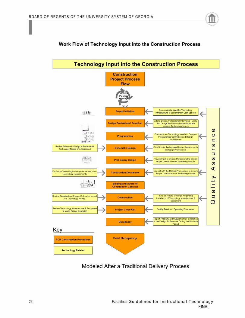
Work Flow of Technology Input into the Construction Process
3 - 5 Pre Planning Meetings
Technology Input into the Construction Process
Construction Project Process
Flow
Project Initiation
Design Professional Selection
Programming
Schematic Design
Preliminary Design
Construction Documents
Bidding and Award of Construction Contract
Construction
Project Close-Out
Occupancy
Post Occupancy
Communicate Need for Technology Infrastructure & Equipment in User Spaces
Attend Design Professional Interviews - Verify that Design Professional can Adequately
address Technology Issues
Communicate Technology Needs to Campus Programming Committee and Design
Professional
Give Special Technology Design Requirements to Design Professional
Provide Input to Design Professional to Ensure Proper Coordination of Technology Issues
Input at Jobsite Meetings Regarding Installation of Technology Infrastructure &
Equipment
Certify Receipt of Operating Documents
Report Problems with Equipment or Installation to the Design Professional During the Warranty
Period
Review Schematic Design to Ensure that Technology Needs are Addressed
Verify that Value Engineering Alternatives meet Technology Requirements
Review Construction Change Orders for Impacton Technology Needs
Review Technology Infrastructure & Equipment to Verify Proper Operation
Q u
a l
i t y
A
s s
u r a
n c
e
Consult with the Design Professional to Ensure Proper Coordination of Technology Issues
KeyBOR Construction Procedures
Technology Related
Modeled After a Traditional Delivery Process
BOARD OF REGENTS OF THE UNIVERSITY SYSTEM OF GEORGIA
24 Facilities Guidel ines for Instruct ional Technology FINAL
BLANK
BOARD OF REGENTS OF THE UNIVERSITY SYSTEM OF GEORGIA
25 Facilities Guidel ines for Instruct ional Technology FINAL
This section outlines general systems criteria that need to be considered for the various space types. When planning for environments that support functions using instructional technology, the following criteria should be considered: • Seating • Sightlines • Lighting • Sound • Quality of Finishes • HVAC • Telecommunication • Miscellaneous
It is important to note these guidelines are written using the concept of ‘wired’ power and technology access. Future advances in the use of ‘wireless’ access should be monitored and may be considered if applicable. In addition, the guidelines are written using the 2000 Pre Planning Guidelines as a reference. This criteria is provided as a starting point and should be evaluated against the most current developments in the industry.
GENERAL CRITERIA
BOARD OF REGENTS OF THE UNIVERSITY SYSTEM OF GEORGIA
26 Facilities Guidel ines for Instruct ional Technology FINAL
BLANK
BOARD OF REGENTS OF THE UNIVERSITY SYSTEM OF GEORGIA
27 Facilities Guidel ines for Instruct ional Technology FINAL
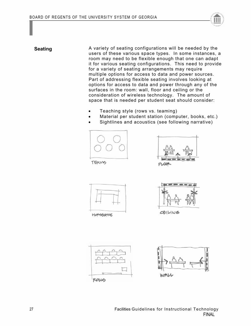
A variety of seating configurations will be needed by the users of these various space types. In some instances, a room may need to be flexible enough that one can adapt it for various seating configurations. This need to provide for a variety of seating arrangements may require multiple options for access to data and power sources. Part of addressing flexible seating involves looking at options for access to data and power through any of the surfaces in the room: wall, floor and ceiling or the consideration of wireless technology. The amount of space that is needed per student seat should consider: • Teaching style (rows vs. teaming) • Material per student station (computer, books, etc.) • Sightlines and acoustics (see following narrative)
Seating
BOARD OF REGENTS OF THE UNIVERSITY SYSTEM OF GEORGIA
28 Facilities Guidel ines for Instruct ional Technology FINAL
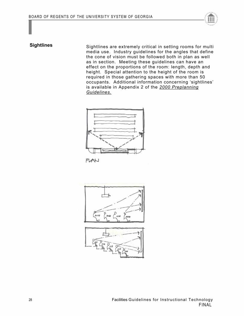
Sightlines are extremely critical in setting rooms for multi media use. Industry guidelines for the angles that define the cone of vision must be followed both in plan as well as in section. Meeting these guidelines can have an effect on the proportions of the room: length, depth and height. Special attention to the height of the room is required in those gathering spaces with more than 50 occupants. Additional information concerning ‘sightlines’ is available in Appendix 2 of the 2000 Preplanning Guidelines.
Sightlines
BOARD OF REGENTS OF THE UNIVERSITY SYSTEM OF GEORGIA
29 Facilities Guidel ines for Instruct ional Technology FINAL
Guidelines for lighting are described in detail in the 2000 Pre-Planning Guidelines. Key points from this document include:
“Control of ambient light becomes critical in front projection environments. This is because ambient light falling on the screen will also be reflected back to the viewers washing out images projected on the screen. Since the area around the projection screen must be able to be darkened considerably while maintaining necessary lighting levels at student and instructor positions, careful control of room lighting and daylight entering through windows is required.
While diffuse indirect lighting is desirable for general classroom use, indirect lighting should not be used during presentations where front projection is required. A direct, controlled lighting component must be provided for use during these presentations.
The lighting fixtures should be grouped in zones to allow various areas of the room to be controlled separately. General direct lighting, wallwash lighting and indirect lighting (if provided) should be in separate zones. Accent lighting, step lighting and lighting for other specific areas should also be in separate zones.
The lighting zones should enable the area around the projection screen to remain darkened (and thereby minimize stray light falling on the projection screen) while illuminating a presenter at either side of the screen. The zoning should also allow sufficient light to remain on over seating areas so notes can be taken. Similar zoning is appropriate for lecture hall/classrooms with front screen video projection. Note that lighting fixture locations will need to be coordinated with ceiling mounted video projector placement.”
Switches or control panels for the zoned lighting should be located at the front of the room near the instructor’s stand and at the back of the room next to the door. Lighting issues should be addressed if televisions, ceiling mounted projectors or wall mounted video displays are to be installed. In addition, all windows and skylights should be equipped with blinds or other devices that block natural light.
Lighting
BOARD OF REGENTS OF THE UNIVERSITY SYSTEM OF GEORGIA
30 Facilities Guidel ines for Instruct ional Technology FINAL
BOARD OF REGENTS OF THE UNIVERSITY SYSTEM OF GEORGIA
31 Facilities Guidel ines for Instruct ional Technology FINAL
Guidelines for sound and acoustics are described in detail in the 2000 Pre-Planning Guidelines. Key points from this document include:
“Acoustical characteristics in presentation spaces are particularly important as speech intelligibility can be degraded by excessive reverberation (and/or echoes) and excessive background noise. Traditionally, classrooms have been constructed with minimal amounts of acoustically absorptive materials and acoustical deficiencies have been tolerated. In presentations where there is no live presenter, the intelligibility of the program is dependent on the quality of the audio recording, the audio playback system and the acoustics of the space. A common acoustical deficiency is excessive reverberation. Reverberation can be controlled by using acoustically absorptive materials such as mineral fiber or fiberglass ceiling tile, fiberglass wall panels and carpet. Carpet can also reduce noise from students shifting in their seats. Note the front third of the ceiling should be hard surfaced (e.g., gypsum board) to help reflect sound from the presenter to the students. Sound isolation between classroom spaces becomes more challenging with the introduction of instructional presentation systems. Traditionally, classroom walls have been designed to provide adequate speech privacy between adjacent spaces. However, with the potentially wider frequency range of sound used in audio/video programs, particularly where music or sound effects are introduced, traditionally acceptable wall constructions may not provide adequate sound isolation, particularly at low frequencies. Wall construction with a Sound Transmission Class (STC) of (STC57 or better should be used to separate classrooms equipped with audio program playback systems. Another common problem in classrooms is noise from heating and air conditioning systems. Classroom Heating, Ventilating and Air Conditioning (HVAC) systems should be designed in accordance with guidelines and criteria published by the American Society of Heating,
Sound & Acoustics
BOARD OF REGENTS OF THE UNIVERSITY SYSTEM OF GEORGIA
32 Facilities Guidel ines for Instruct ional Technology FINAL
Refrigerating and Air Conditioning Engineers (ASHRAE). In general, system components with fans, compressors, etc., should not be located within or immediately adjacent to classroom spaces. Finally, diffusers should be placed so that air currents do not displace projection screens since this can blur projected images.”
BOARD OF REGENTS OF THE UNIVERSITY SYSTEM OF GEORGIA
33 Facilities Guidel ines for Instruct ional Technology FINAL
Guidelines for finishes are described in detail in the 2000 Pre-Planning Guidelines. Key points from this are:
Room finishes (surfaces and furniture) should be selected for control of reflected light and glare while retaining sufficient surface luminance to provide an efficient and comfortable environment. Walls should be 30% to 50% reflective. Floor finishes and work surfaces should be 30% reflective or less. Ceilings should be 70% to 90% reflective. Windows and doors vision panels should be outfitted with low maintenance shades, so that the room could be made completely dark with all l ights turned off. Note, however, that for safety considerations, at no time should the room be completely dark. Low levels of light from the overhead direct lighting fixtures or step lighting fixtures (in tiered rooms) should maintain sufficient il lumination to allow safe exit from the room at all times. Emergency lighting fixtures may be part of the normal lighting system and may, in general, be dimmed. However, designated emergency lighting fixtures must revert to emergency light levels automatically in emergency situations. Refer to applicable electrical codes and the authority having jurisdiction regarding the dimming and control of emergency lighting fixtures.
Quality of Finishes
BOARD OF REGENTS OF THE UNIVERSITY SYSTEM OF GEORGIA
34 Facilities Guidel ines for Instruct ional Technology FINAL
Many instructional spaces are being outfitted with data, video, and multi-media to the classroom and/or learning laboratories. In some cases the approach has been to address only the need for wiring and electronics installations. The results are spaces that may not meet standards for heating and cooling comfort. Sufficient cooling and humidity control capacity is needed if any type of computerized equipment is to be extensively used in a room.
Classrooms Most classrooms are designed for heating and cooling based on
the heat loss of the building skin and the heat gain from the building skin, lights, and the maximum number of people in the space. When a classroom of 30 students is turned into a classroom of 25 workstations and 25 students the internal load increases dramatically, in some instances, up to four times. This has an impact on the mechanical system as well as the electrical system.
Computer cluster rooms with adequate cooling are often occupied
as much as 18-20 hours or more a day. That amount of occupied time does not giving the room time to cool off and to freshen up from the human odors and limited oxygen. In addition, CRT monitors give off a very limited amount of ozone, in trace or less levels, but when 20 to 30 are in a confined space will require ventilation of fresh air to maintain safe levels. A building 10 years and older may not have adequate fresh air. It is recommended that the Facilities and/or design engineering firm be consulted concerning the comfort requirements as well as the electrical requirements in order to achieve a useful classroom or laboratory.
Offices Under normal conditions adding 2 desktop computers and printers
normally will not present a comfort problem. Adding beyond 2 to an office will require additional HVAC and fresh air.
IDR/MDR (Intermediate Distribution Room/Main Distribution Room)
The MDR spaces needs to be evaluated by a Mechanical Engineer and provide HVAC services as needed. Be sure to account for not only the institutions equipment but also consult with the local telephone service provider and your network access provider. They will also want to place their equipment in the MDR room.
1. It is recommended that the IDR/MDR rooms be evaluated for
their HVAC needs and that the ANSI/EIA/TIA 568 B and the ANSIEIA/TIA 569 B standards should be followed.
2. ANSI/ASHARE Standard 62-1995 ventilation standards should be followed for renovations and new construction.
HVAC
BOARD OF REGENTS OF THE UNIVERSITY SYSTEM OF GEORGIA
35 Facilities Guidel ines for Instruct ional Technology FINAL
Recommend redundant HVAC system in MDR. Typically, the loss associated with overheated systems will be many times the cost of the second HVAC unit. It is important to establish an ‘optimal’ size for IDR and MDR rooms. In doing so, consideration should be given to the ‘width’ of these rooms, particularly the IDR.
BOARD OF REGENTS OF THE UNIVERSITY SYSTEM OF GEORGIA
36 Facilities Guidel ines for Instruct ional Technology FINAL
Networking infrastructure should be thorough and comprehensive. If the room is designed for use of laptops, hard-wire data ports should be located at seating location. Otherwise, the appropriate number of wireless transmitters should be considered in place of hard-wire. This is especially critical if retrofitting an existing structure. When using ‘wired’ design, consideration should be given to the maximum length of cable.
The design of an intra-building backbone between the main entrance room (MER) and the intermediate data room (IDR) the horizontal cross-connect (HC) for the floor distribution is the method of sub-dividing the main entrance facilities and distributing the data/telephone/video facilities to other floors in the building for further subdivision to the users. The two primary design options of intra-building backbones are:
• Star, where the intermediate data room (IDR) is connected
directly to the building’s main entrance room (MER). It is preferred to stack the intermediate data rooms to align the vertical cable pulls.
• Hierarchical star, where some or all of the intermediate data rooms (IDR) are connected to an intermediate cross connect which in turn is connected to the building’s main entrance room (ME).
In general, the best design is the star design between the buildings’ main entrance room and the intermediate data rooms on each floor. However, in some extremely large buildings (e. g., a high- rise), a hierarchical star may be considered. Examine trade-offs between different size cables and labor to determine a suitable cost-effective solution. Applications may influence the decision.
Intra-building Backbone Distribution Systems
A buildings system backbone distribution for voice/data/video/other system should be a vertical star system from the main entrance room of each system to the intermediate data room of each system.
Main Entrance Rooms (MERs) and Network Interface Wiring
Ideally, the main entrance room would be co-located in the data network equipment along with (in some cases) a telephone PBX, security monitoring equipment, and other active equipment serving the building. An intra-building network should have only one main entrance room (MER).
See Appendix for cable types.
Telecommunications and Cabling
BOARD OF REGENTS OF THE UNIVERSITY SYSTEM OF GEORGIA
37 Facilities Guidel ines for Instruct ional Technology FINAL
Vertically Aligned Telecommunications Intermediate Data Rooms (IDRs)/Termination Rooms (TR)
Vertically aligned IDRs with connecting sleeves or slots are the most common type of backbone pathway. The advantage of using vertically aligned IDRs is flexibility because the: • Backbone cable sheath is accessible on each floor. • Circuits can be distributed as required.
See Appendix for Fiber types and applications.
Inter-building Campus Backbone Planning
Backbone cabling should be designed and installed to satisfy an entire site planning period or anticipated life cycle. Treat a campus backbone system as one project for telecommunications purposes. Refer to the following list for recommended fiber counts based on building use/occupancy:
• Residential or Small Admin 12mm/12sm • Large Admin or Small Academic 24mm/24sm • Large Academic or Small Research 36mm/36sm • Large Research 48mm/48sm
BOARD OF REGENTS OF THE UNIVERSITY SYSTEM OF GEORGIA
38 Facilities Guidel ines for Instruct ional Technology FINAL
Many Colleges and Universities have found it desirable to augment their teaching delivery methods by recording, producing on campus, and receiving satellite feeds from other campus program materials and replaying these class lectures, live broadcast and other materials related to the learning experience to the classrooms and dormitories within a campus. There are several other methods of obtaining program materials:
• Off- the- air antennas may be mounted on a pole or tower. • CATV feeds are broadband RF signals from a CATV company. • A videocassette recorder/ player (VCR) can be used to
generate local programs. • A digital versatile disc (DVD) is a compact disc (CD) that
contains full- motion video, such as movies. • Camera inputs form campus locations
It has become desirable to install in new buildings and renovation projects a CATV distribution system to support these academic requirements. CATV requirements should be continually reviewed with each project.
Elements of a Cable System
• A typical cable system consists of three basic elements: • Head-end— An equipment room that contains the electronics
for receiving and processing TV programs. The output of the head-end connects to the distribution system.
• Distribution System— A network of distribution media such as coax or fiber optic cables, amplifiers, and passive devices such as couplers and splitters.
• Room/location Drop— The taps, cable, and outlet where the users connect the TV set. The room/location drop is connected to the distribution system at the tap normally in the telecommunications room on each floor.
Proof of Performance Testing
A thorough knowledge of CATV systems, standards, and test equipment is required to properly evaluate the performance of a system. The FCC may fine the owner of the system if certain performance characteristics are not met. Proof of performance testing is necessary, and is often contractually required to certify that the CATV system operates as designed. Testing the system involves using the appropriate test equipment to ensure that the system and all its components meet the overall design specifications. Testing should address 2-way capabilities, to receive broadcasts or to send them back to the headend for redistribution.
MISCELLANEOUS
Cable TV
BOARD OF REGENTS OF THE UNIVERSITY SYSTEM OF GEORGIA
39 Facilities Guidel ines for Instruct ional Technology FINAL
In addition to standard installation, sufficient electrical outlets should be provided to supply any portable equipment such as computers, laptops, and any other media product. The points of access should be located where this equipment might be positioned. If extended use of laptops is expected, power to individual seating locations will provide the necessary backup power for batteries.
If a computer is permanently installed in this room, then the instructor’s desk should be lockable for both the personal computer and the monitor. Otherwise, the instructor needs to transport a laptop computer. If the room is converted into a high tech computer classroom or instructional laboratory, then it should be secured with a card access system or some other similar device.
Compliance with Americans with Disabilities Act and other
Applicable Codes and Standards as related to Technology Standards. All facilities should provide handicapped students full access (Office for Civil Rights 1999). Enacted in 1990, the ADA prohibits the discrimination against persons with physical and mental disabilities. Title II of the ADA states that public institutions can choose to follow either the UFAS (Uniform Federal Accessibility Standards) or ADAAG (Americans with Disabilities Act Accessibility Guidelines for Building and Facilities) standards. The goal for designing classroom is to keep in mind persons with mobility, hearing, vision, and mental disabilities. The two most dominant disabilities to address are mobility and hearing impaired
Mobility Impaired: Adequate space to enter into and maneuver
around a classroom should be provided for students who are wheelchair bound. Four feet spacing between rows as well as aisles is adequate for manual or motorized wheelchairs. If standard tables, which are 29” in height, are used in the classroom, then tables which are either 31” in height or adjustable needs to be available for wheelchair bound students.
Hearing Impaired: . ADA requires assistive listening devices for at
least 4% of the seats, with a minimum of 2. The transmitter can be located in the media cabinet. If classrooms that accommodate at least 50 students are under construction or if they have audio-amplification systems and fixed seating, then they must have a permanently installed assisted listening system. These systems typically broadcast audio as an infrared or FM signal. In existing locations, assisted listening systems may be permanent or portable. If there is a fire alarm in the classroom, then there must be an emergency strobe light for the hearing impaired.
These requirements apply to all users: students, faculty and staff.
Power
Security
ADA
BOARD OF REGENTS OF THE UNIVERSITY SYSTEM OF GEORGIA
40 Facilities Guidel ines for Instruct ional Technology FINAL
These guidelines are written using ‘wired’ technology as a basis
for planning. However, given the advances in technology and the rapid increase in wireless communication, strong consideration must be given to the use of wireless capability.
Wireless
BOARD OF REGENTS OF THE UNIVERSITY SYSTEM OF GEORGIA
41 Facilities Guidel ines for Instruct ional Technology FINAL
ROOM DESCRIPTIONS
This section describes “baseline” purpose and characteristics of the room types. Content of this section is:
• Classrooms Standard Classroom (lecture 25-60 student stations)
Advanced Classroom (lecture 25-60 student stations)
High Technology classroom (lecture 20-40 student stations) Auditoria/Large Lecture Hall (lecture 100-250 students) Standard Seminar Hi Tech Seminar • Laboratories Wet Laboratories Dry Laboratories Computer Lab – Instructional Computer Lab – Open (Self-instruction) • Offices
Administrative Offices Faculty Administrative Suites
Faculty Offices
• Informal Study Rooms Informal Collaborative Areas
BOARD OF REGENTS OF THE UNIVERSITY SYSTEM OF GEORGIA
42 Facilities Guidel ines for Instruct ional Technology FINAL
BLANK
BOARD OF REGENTS OF THE UNIVERSITY SYSTEM OF GEORGIA
43 Facilities Guidel ines for Instruct ional Technology FINAL
These guidelines identify room parameters and the technology required to support program objectives. The guidelines for the following room types are reasonable projections of the needs for selected purposes and establish baseline minimum. Institutions must consider there specific mission carefully in providing additional enhancement.
Classrooms Classrooms are likely to be used to support several different academic programs and should be designed to accommodate the full range of modern electronic instructional support capabilities. They should be designed to accommodate the teaching methodologies that best support the academic discipline(s) for which the building is being designed. The design of all classrooms should incorporate proportions such that the room has functional length to width and floor to ceiling characteristics. It is important that each classroom has anticipated the faculty-instruction needs by providing, as required, technology requirements, video projections capabilities, power and data service needs, and similar features.
Classrooms
BOARD OF REGENTS OF THE UNIVERSITY SYSTEM OF GEORGIA
44 Facilities Guidel ines for Instruct ional Technology FINAL
BLANK
BOARD OF REGENTS OF THE UNIVERSITY SYSTEM OF GEORGIA
45 Facilities Guidel ines for Instruct ional Technology FINAL
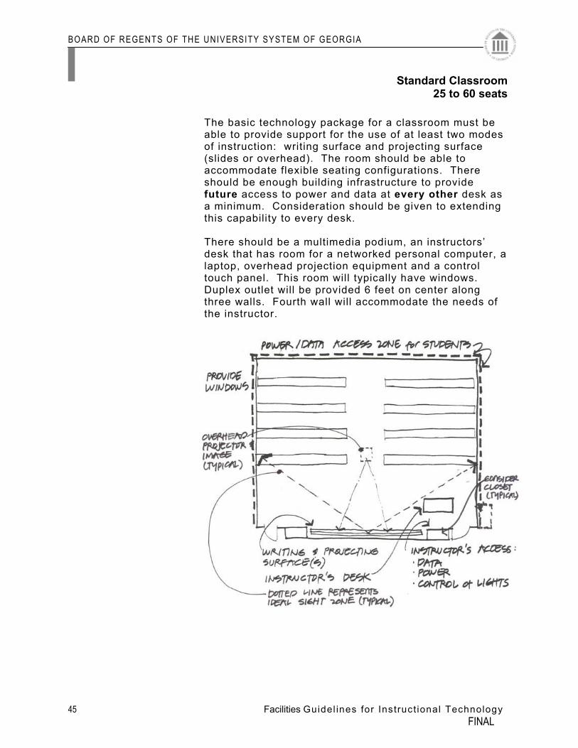
The basic technology package for a classroom must be
able to provide support for the use of at least two modes of instruction: writing surface and projecting surface (slides or overhead). The room should be able to accommodate flexible seating configurations. There should be enough building infrastructure to provide future access to power and data at every other desk as a minimum. Consideration should be given to extending this capability to every desk.
There should be a multimedia podium, an instructors’
desk that has room for a networked personal computer, a laptop, overhead projection equipment and a control touch panel. This room will typically have windows. Duplex outlet will be provided 6 feet on center along three walls. Fourth wall will accommodate the needs of the instructor.
Standard Classroom25 to 60 seats
BOARD OF REGENTS OF THE UNIVERSITY SYSTEM OF GEORGIA
46 Facilities Guidel ines for Instruct ional Technology FINAL
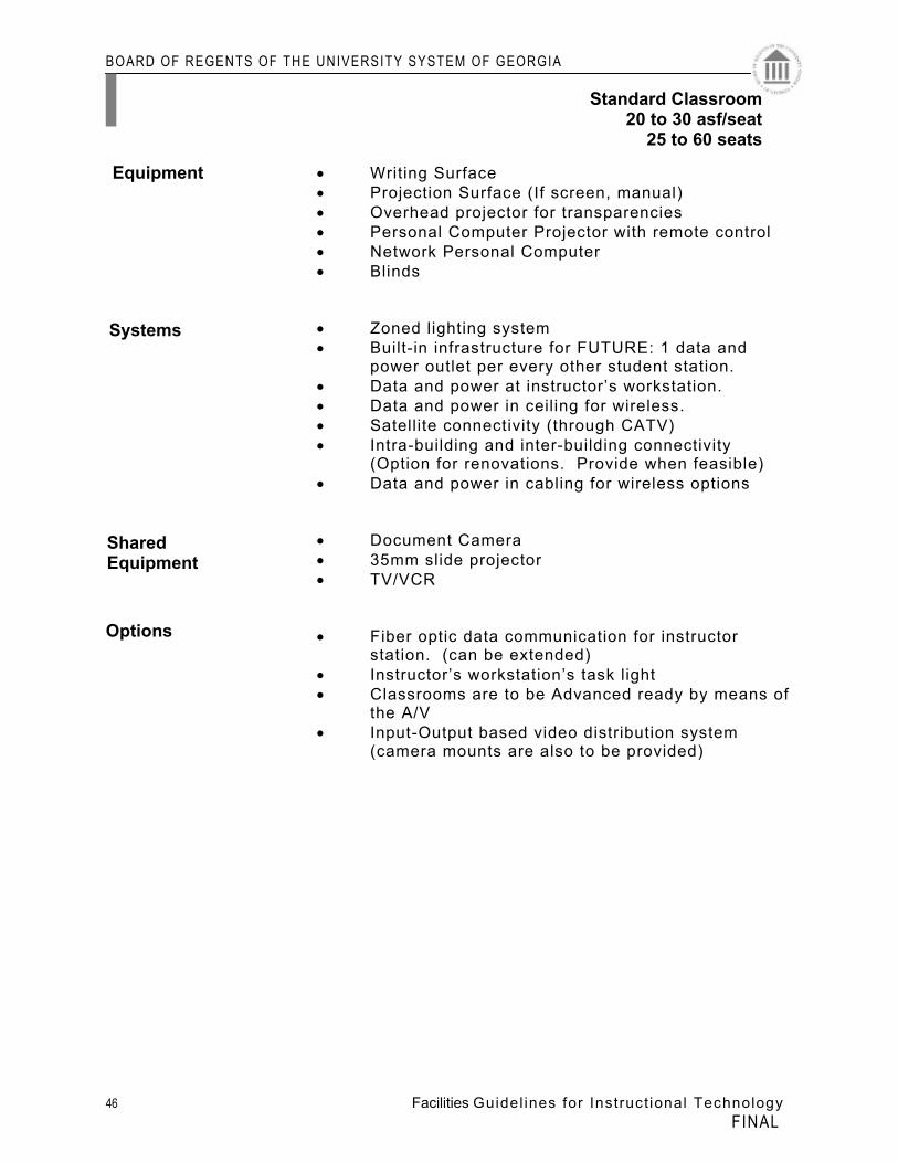
• Writing Surface • Projection Surface (If screen, manual) • Overhead projector for transparencies • Personal Computer Projector with remote control • Network Personal Computer • Blinds • Zoned lighting system • Built-in infrastructure for FUTURE: 1 data and
power outlet per every other student station. • Data and power at instructor’s workstation. • Data and power in ceiling for wireless. • Satellite connectivity (through CATV) • Intra-building and inter-building connectivity
(Option for renovations. Provide when feasible) • Data and power in cabling for wireless options • Document Camera • 35mm slide projector • TV/VCR • Fiber optic data communication for instructor
station. (can be extended) • Instructor’s workstation’s task light • Classrooms are to be Advanced ready by means of
the A/V • Input-Output based video distribution system
(camera mounts are also to be provided)
Systems
Shared Equipment
Options
Equipment
Standard Classroom20 to 30 asf/seat
25 to 60 seats
BOARD OF REGENTS OF THE UNIVERSITY SYSTEM OF GEORGIA
47 Facilities Guidel ines for Instruct ional Technology FINAL
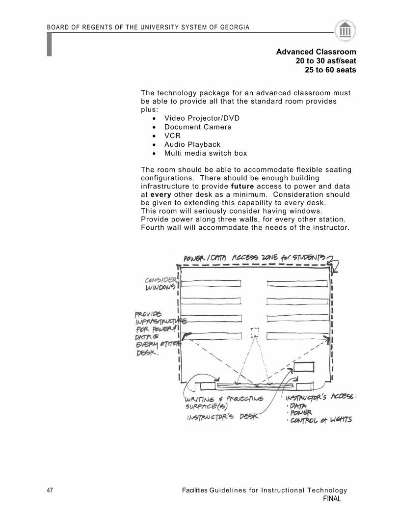
The technology package for an advanced classroom must
be able to provide all that the standard room provides plus:
• Video Projector/DVD • Document Camera • VCR • Audio Playback • Multi media switch box
The room should be able to accommodate flexible seating
configurations. There should be enough building infrastructure to provide future access to power and data at every other desk as a minimum. Consideration should be given to extending this capability to every desk. This room will seriously consider having windows. Provide power along three walls, for every other station. Fourth wall will accommodate the needs of the instructor.
Advanced Classroom20 to 30 asf/seat
25 to 60 seats
BOARD OF REGENTS OF THE UNIVERSITY SYSTEM OF GEORGIA
48 Facilities Guidel ines for Instruct ional Technology FINAL
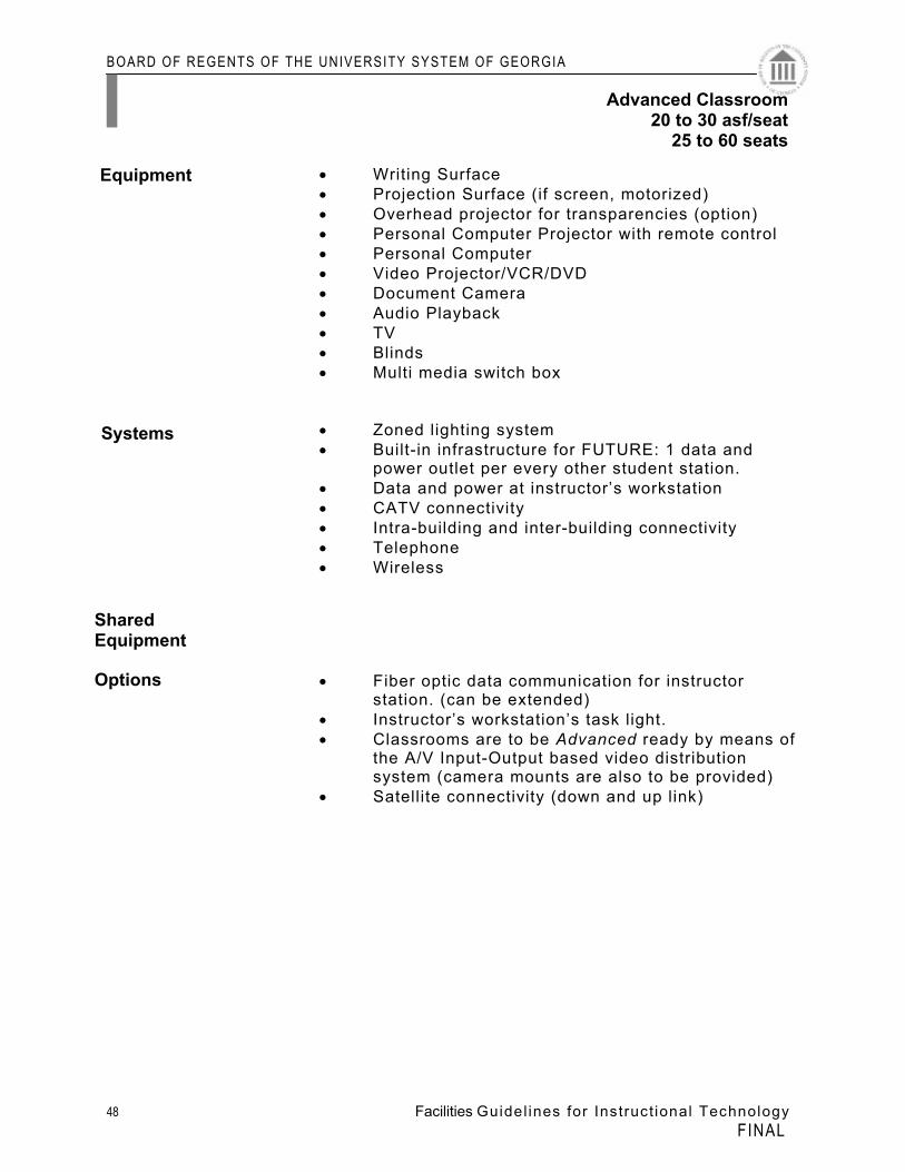
• Writing Surface • Projection Surface (if screen, motorized) • Overhead projector for transparencies (option) • Personal Computer Projector with remote control • Personal Computer • Video Projector/VCR/DVD • Document Camera • Audio Playback • TV • Blinds • Multi media switch box • Zoned lighting system • Built-in infrastructure for FUTURE: 1 data and
power outlet per every other student station. • Data and power at instructor’s workstation • CATV connectivity • Intra-building and inter-building connectivity • Telephone • Wireless • Fiber optic data communication for instructor
station. (can be extended) • Instructor’s workstation’s task light. • Classrooms are to be Advanced ready by means of
the A/V Input-Output based video distribution system (camera mounts are also to be provided)
• Satellite connectivity (down and up link)
Systems
Shared Equipment Options
Equipment
Advanced Classroom20 to 30 asf/seat
25 to 60 seats
BOARD OF REGENTS OF THE UNIVERSITY SYSTEM OF GEORGIA
49 Facilities Guidel ines for Instruct ional Technology FINAL
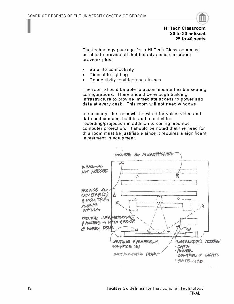
The technology package for a Hi Tech Classroom must be able to provide all that the advanced classroom provides plus:
• Satellite connectivity • Dimmable lighting • Connectivity to videotape classes
The room should be able to accommodate flexible seating
configurations. There should be enough building infrastructure to provide immediate access to power and data at every desk. This room will not need windows.
In summary, the room will be wired for voice, video and
data and contains built-in audio and video recording/projection in addition to ceiling mounted computer projection. It should be noted that the need for this room must be justifiable since it requires a significant investment in equipment.
Hi Tech Classroom20 to 30 asf/seat
25 to 40 seats
BOARD OF REGENTS OF THE UNIVERSITY SYSTEM OF GEORGIA
50 Facilities Guidel ines for Instruct ional Technology FINAL
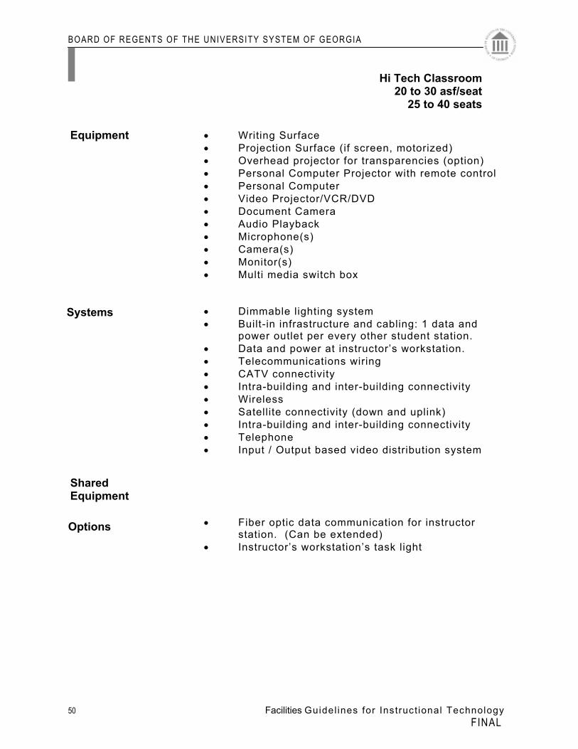
• Writing Surface • Projection Surface (if screen, motorized) • Overhead projector for transparencies (option) • Personal Computer Projector with remote control • Personal Computer • Video Projector/VCR/DVD • Document Camera • Audio Playback • Microphone(s) • Camera(s) • Monitor(s) • Multi media switch box • Dimmable lighting system • Built-in infrastructure and cabling: 1 data and
power outlet per every other student station. • Data and power at instructor’s workstation. • Telecommunications wiring • CATV connectivity • Intra-building and inter-building connectivity • Wireless • Satellite connectivity (down and uplink) • Intra-building and inter-building connectivity • Telephone • Input / Output based video distribution system • Fiber optic data communication for instructor
station. (Can be extended) • Instructor’s workstation’s task light
Systems
Shared Equipment Options
Equipment
Hi Tech Classroom20 to 30 asf/seat
25 to 40 seats
BOARD OF REGENTS OF THE UNIVERSITY SYSTEM OF GEORGIA
51 Facilities Guidel ines for Instruct ional Technology FINAL
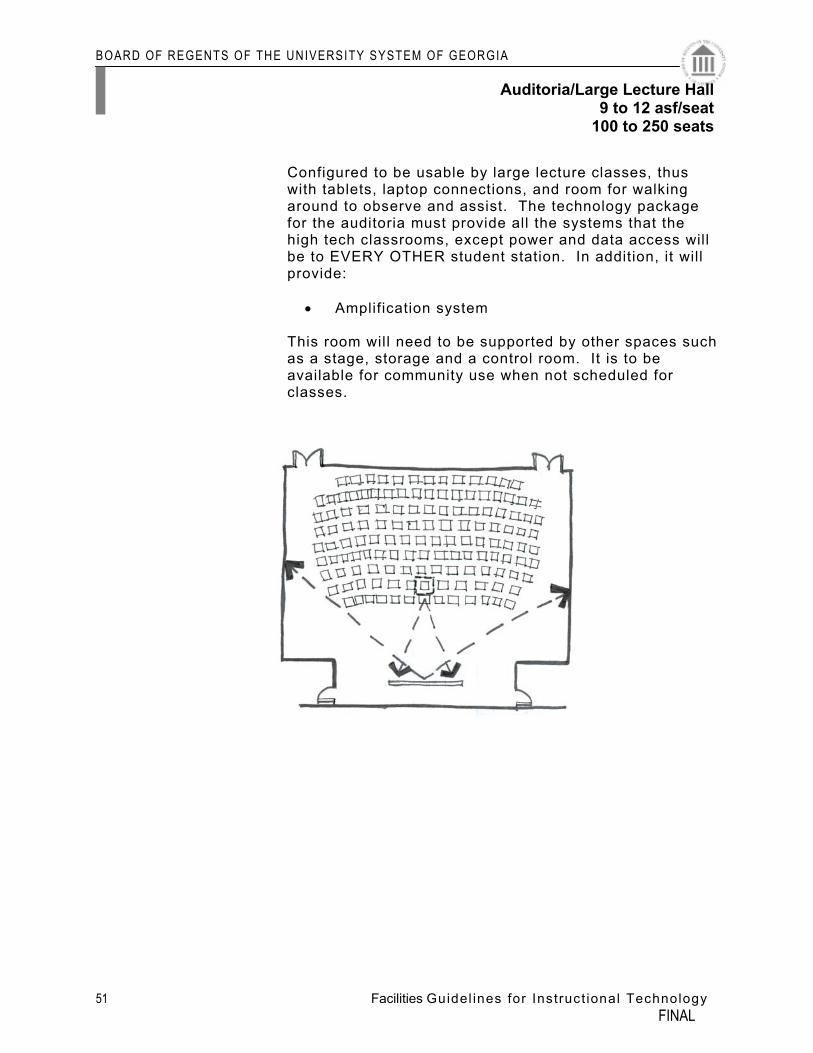
Configured to be usable by large lecture classes, thus with tablets, laptop connections, and room for walking around to observe and assist. The technology package for the auditoria must provide all the systems that the high tech classrooms, except power and data access will be to EVERY OTHER student station. In addition, it will provide:
• Amplification system
This room will need to be supported by other spaces such as a stage, storage and a control room. It is to be available for community use when not scheduled for classes.
Auditoria/Large Lecture Hall9 to 12 asf/seat
100 to 250 seats
BOARD OF REGENTS OF THE UNIVERSITY SYSTEM OF GEORGIA
52 Facilities Guidel ines for Instruct ional Technology FINAL
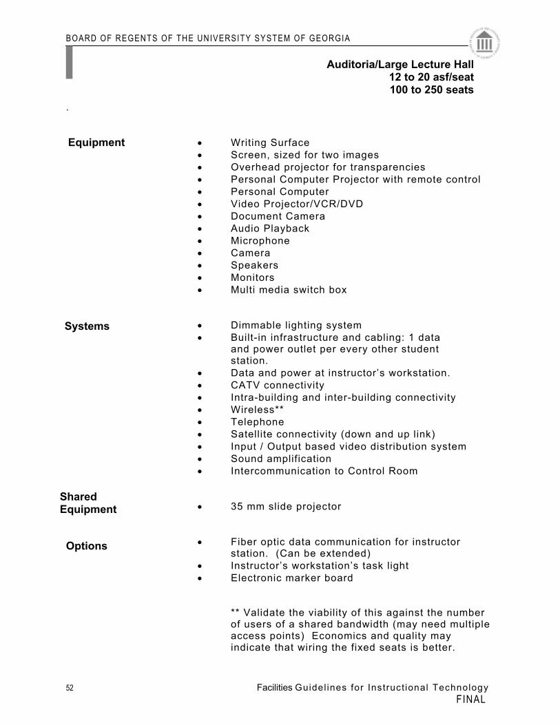
.
• Writing Surface • Screen, sized for two images • Overhead projector for transparencies • Personal Computer Projector with remote control • Personal Computer • Video Projector/VCR/DVD • Document Camera • Audio Playback • Microphone • Camera • Speakers • Monitors • Multi media switch box • Dimmable lighting system • Built-in infrastructure and cabling: 1 data and power outlet per every other student station. • Data and power at instructor’s workstation. • CATV connectivity • Intra-building and inter-building connectivity • Wireless** • Telephone • Satellite connectivity (down and up link) • Input / Output based video distribution system • Sound amplification • Intercommunication to Control Room • 35 mm slide projector • Fiber optic data communication for instructor
station. (Can be extended) • Instructor’s workstation’s task light • Electronic marker board
** Validate the viability of this against the number of users of a shared bandwidth (may need multiple access points) Economics and quality may indicate that wiring the fixed seats is better.
Systems
Shared Equipment
Options
Equipment
Auditoria/Large Lecture Hall12 to 20 asf/seat100 to 250 seats
BOARD OF REGENTS OF THE UNIVERSITY SYSTEM OF GEORGIA
53 Facilities Guidel ines for Instruct ional Technology FINAL
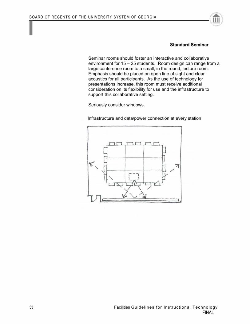
Seminar rooms should foster an interactive and collaborative environment for 15 – 25 students. Room design can range from a large conference room to a small, in the round, lecture room. Emphasis should be placed on open line of sight and clear acoustics for all participants. As the use of technology for presentations increase, this room must receive additional consideration on its flexibility for use and the infrastructure to support this collaborative setting.
Seriously consider windows.
Standard Seminar
Infrastructure and data/power connection at every station
BOARD OF REGENTS OF THE UNIVERSITY SYSTEM OF GEORGIA
54 Facilities Guidel ines for Instruct ional Technology FINAL
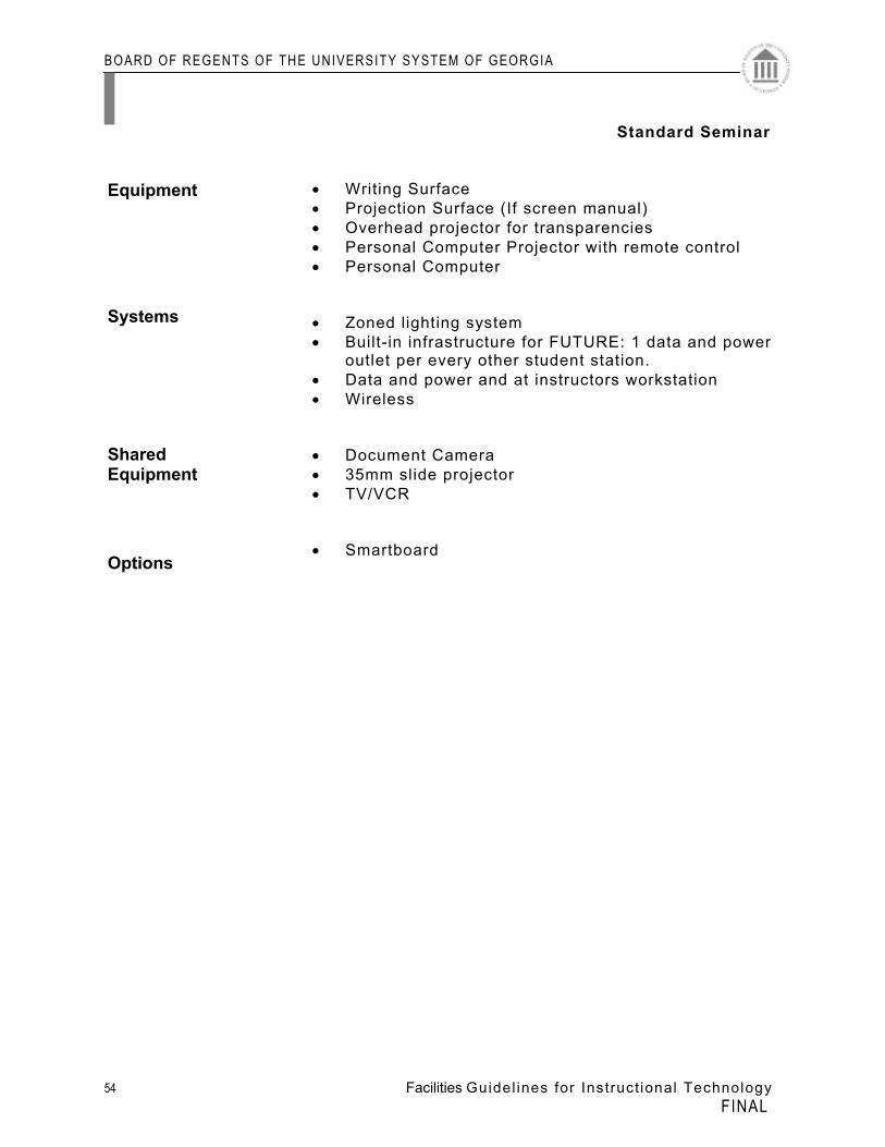
• Writing Surface • Projection Surface (If screen manual) • Overhead projector for transparencies • Personal Computer Projector with remote control • Personal Computer • Zoned lighting system • Built-in infrastructure for FUTURE: 1 data and power
outlet per every other student station. • Data and power and at instructors workstation • Wireless • Document Camera • 35mm slide projector • TV/VCR
• Smartboard
Systems
Shared Equipment
Options
Equipment
Standard Seminar
BOARD OF REGENTS OF THE UNIVERSITY SYSTEM OF GEORGIA
55 Facilities Guidel ines for Instruct ional Technology FINAL
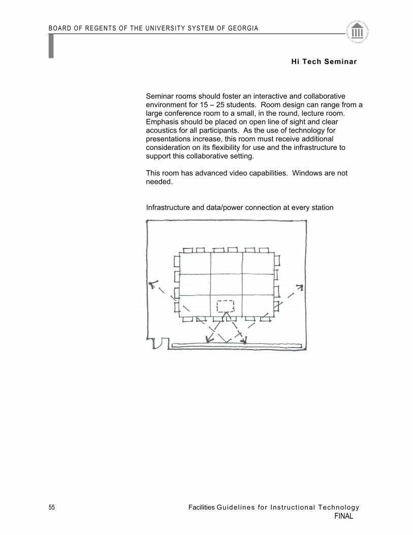
Seminar rooms should foster an interactive and collaborative environment for 15 – 25 students. Room design can range from a large conference room to a small, in the round, lecture room. Emphasis should be placed on open line of sight and clear acoustics for all participants. As the use of technology for presentations increase, this room must receive additional consideration on its flexibility for use and the infrastructure to support this collaborative setting.
This room has advanced video capabilities. Windows are not needed.
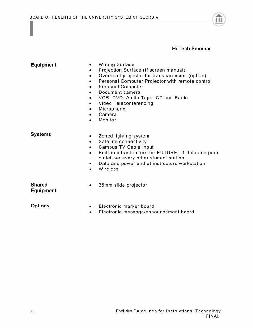
Hi Tech Seminar
Infrastructure and data/power connection at every station
BOARD OF REGENTS OF THE UNIVERSITY SYSTEM OF GEORGIA
56 Facilities Guidel ines for Instruct ional Technology FINAL
• Writing Surface • Projection Surface (If screen manual) • Overhead projector for transparencies (option) • Personal Computer Projector with remote control • Personal Computer • Document camera • VCR, DVD, Audio Tape, CD and Radio • Video Teleconferencing • Microphone • Camera • Monitor • Zoned lighting system • Satellite connectivity • Campus TV Cable Input • Built-in infrastructure for FUTURE: 1 data and poer
outlet per every other student station • Data and power and at instructors workstation • Wireless • 35mm slide projector • Electronic marker board • Electronic message/announcement board
Systems
Shared Equipment
Options
Equipment
Hi Tech Seminar
BOARD OF REGENTS OF THE UNIVERSITY SYSTEM OF GEORGIA
57 Facilities Guidel ines for Instruct ional Technology FINAL
Laboratories If colleges and universities are to build the kind of natural
sciences communities that succeed in attracting and sustaining student interest in science and mathematics, spaces must encourage daily interaction between student and faculty, and between student and student. The relationship of offices, laboratories, common areas, as well as the traffic patterns, has to promote such communities and interactions.
Laboratories, including computer classrooms, require
dedicated support spaces, together with areas reserved for storage and maintenance of computer-related equipment and supplies. Consideration should be given to grouping computer laboratories around, or in the vicinity of, central supporting facilities or data ports. The need for security and 24-hour access, if applicable, should be considered. There is a need to zone HVAC appropriately for independent control. The need for additional power requirements and air conditioning must be accounted for at significant concentrations of computer-related equipment. Attention should be given to the placement of printers, which includes consideration of costs, power and data cabling factors.
Three educational trends specifically affect science
education.
1. Integration of science curriculums is occurring at two levels. First, the traditional boundaries between the life and physical sciences are being dismantled. Second, in general, the sciences are becoming more integrated with other disciplines such as math and history.
2. The implications for science facilities include
considering designing “universal labs” that can accommodate multiple science curriculums and placing science facilities in a central location instead of an isolated wing.
3. Integrating technology. “The global village may be a
cliché,” argues the National Science Teachers Association (NSTA), “but the global classroom is a reality” (NSTA 1999). In enhancing the science curriculum, teachers are looking beyond their classroom walls to develop more relevant and board-based activities. Students are logging onto the Internet to watch frog dissections, download photographs from orbiting satellites, and converse
BOARD OF REGENTS OF THE UNIVERSITY SYSTEM OF GEORGIA
58 Facilities Guidel ines for Instruct ional Technology FINAL
with experts. They are obtaining an in-depth analysis of the functioning of the human body and chemical reactions through interactive computer programs. Telecommunications connect classrooms with other classrooms, universities, and scientific facilities worldwide.
BOARD OF REGENTS OF THE UNIVERSITY SYSTEM OF GEORGIA
59 Facilities Guidel ines for Instruct ional Technology FINAL
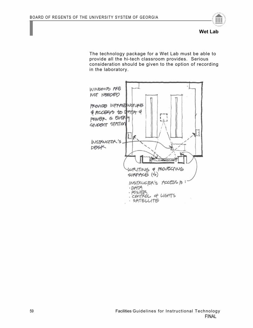
The technology package for a Wet Lab must be able to provide all the hi-tech classroom provides. Serious consideration should be given to the option of recording in the laboratory.
Wet Lab
BOARD OF REGENTS OF THE UNIVERSITY SYSTEM OF GEORGIA
60 Facilities Guidel ines for Instruct ional Technology FINAL
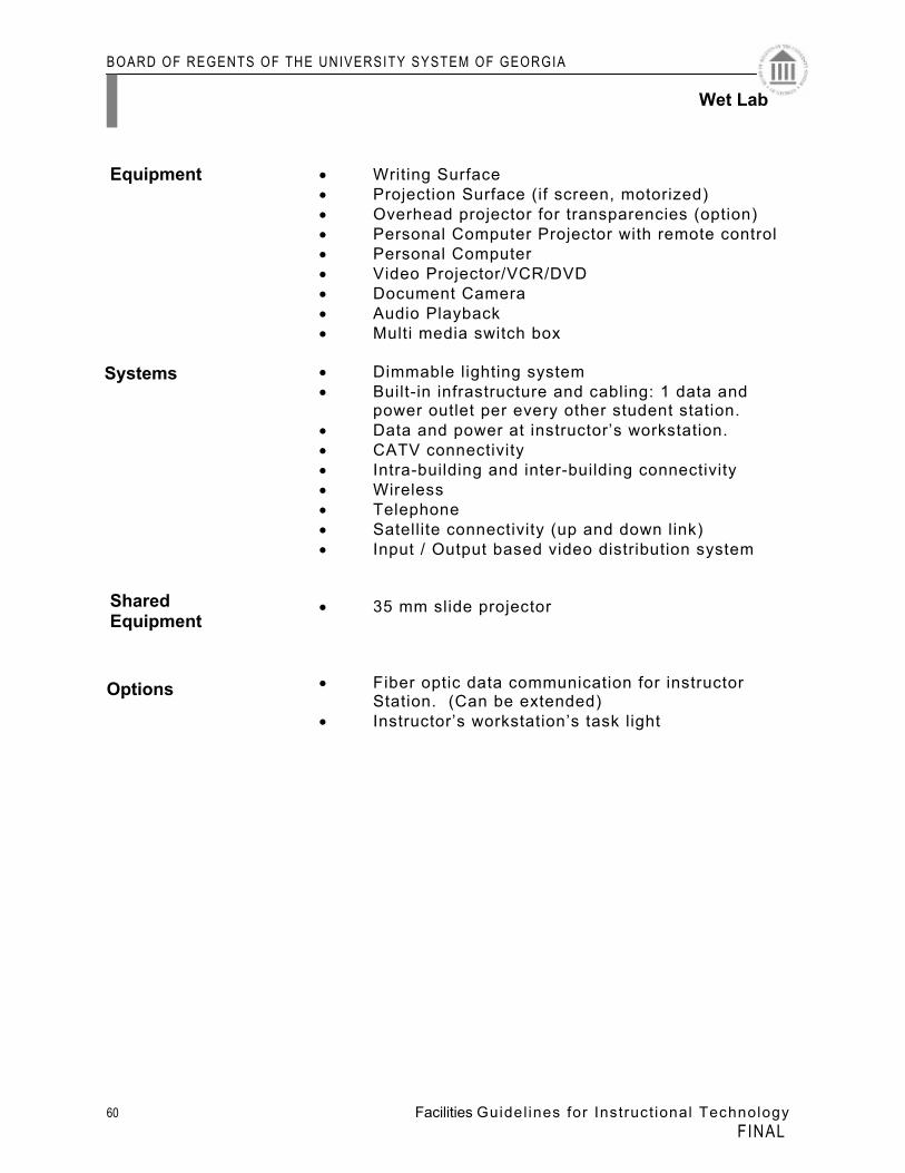
• Writing Surface • Projection Surface (if screen, motorized) • Overhead projector for transparencies (option) • Personal Computer Projector with remote control • Personal Computer • Video Projector/VCR/DVD • Document Camera • Audio Playback • Multi media switch box • Dimmable lighting system • Built-in infrastructure and cabling: 1 data and power outlet per every other student station. • Data and power at instructor’s workstation. • CATV connectivity • Intra-building and inter-building connectivity • Wireless • Telephone • Satellite connectivity (up and down link) • Input / Output based video distribution system • 35 mm slide projector • Fiber optic data communication for instructor Station. (Can be extended) • Instructor’s workstation’s task light
Systems
Shared Equipment
Options
Equipment
Wet Lab
BOARD OF REGENTS OF THE UNIVERSITY SYSTEM OF GEORGIA
61 Facilities Guidel ines for Instruct ional Technology FINAL
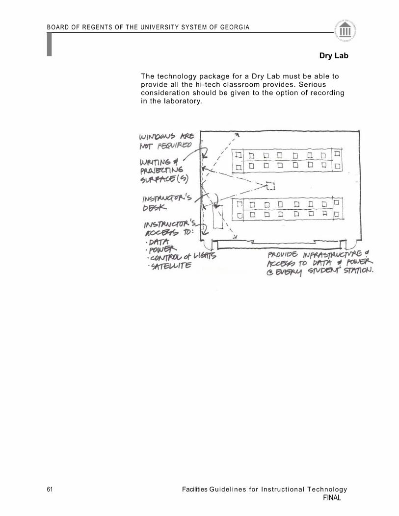
The technology package for a Dry Lab must be able to provide all the hi-tech classroom provides. Serious consideration should be given to the option of recording in the laboratory.
Dry Lab
BOARD OF REGENTS OF THE UNIVERSITY SYSTEM OF GEORGIA
62 Facilities Guidel ines for Instruct ional Technology FINAL
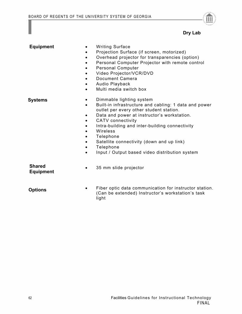
• Writing Surface • Projection Surface (if screen, motorized) • Overhead projector for transparencies (option) • Personal Computer Projector with remote control • Personal Computer • Video Projector/VCR/DVD • Document Camera • Audio Playback • Multi media switch box • Dimmable lighting system • Built-in infrastructure and cabling: 1 data and power
outlet per every other student station. • Data and power at instructor’s workstation. • CATV connectivity • Intra-building and inter-building connectivity • Wireless • Telephone • Satellite connectivity (down and up link) • Telephone • Input / Output based video distribution system • 35 mm slide projector • Fiber optic data communication for instructor station.
(Can be extended) Instructor’s workstation’s task light
Systems
Shared Equipment
Options
Equipment
Dry Lab
BOARD OF REGENTS OF THE UNIVERSITY SYSTEM OF GEORGIA
63 Facilities Guidel ines for Instruct ional Technology FINAL
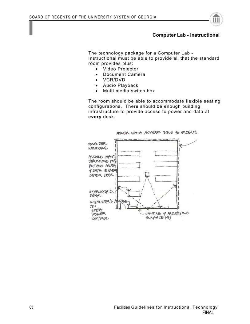
The technology package for a Computer Lab - Instructional must be able to provide all that the standard room provides plus:
• Video Projector • Document Camera • VCR/DVD • Audio Playback • Multi media switch box
The room should be able to accommodate flexible seating configurations. There should be enough building infrastructure to provide access to power and data at every desk.
Computer Lab - Instructional
BOARD OF REGENTS OF THE UNIVERSITY SYSTEM OF GEORGIA
64 Facilities Guidel ines for Instruct ional Technology FINAL
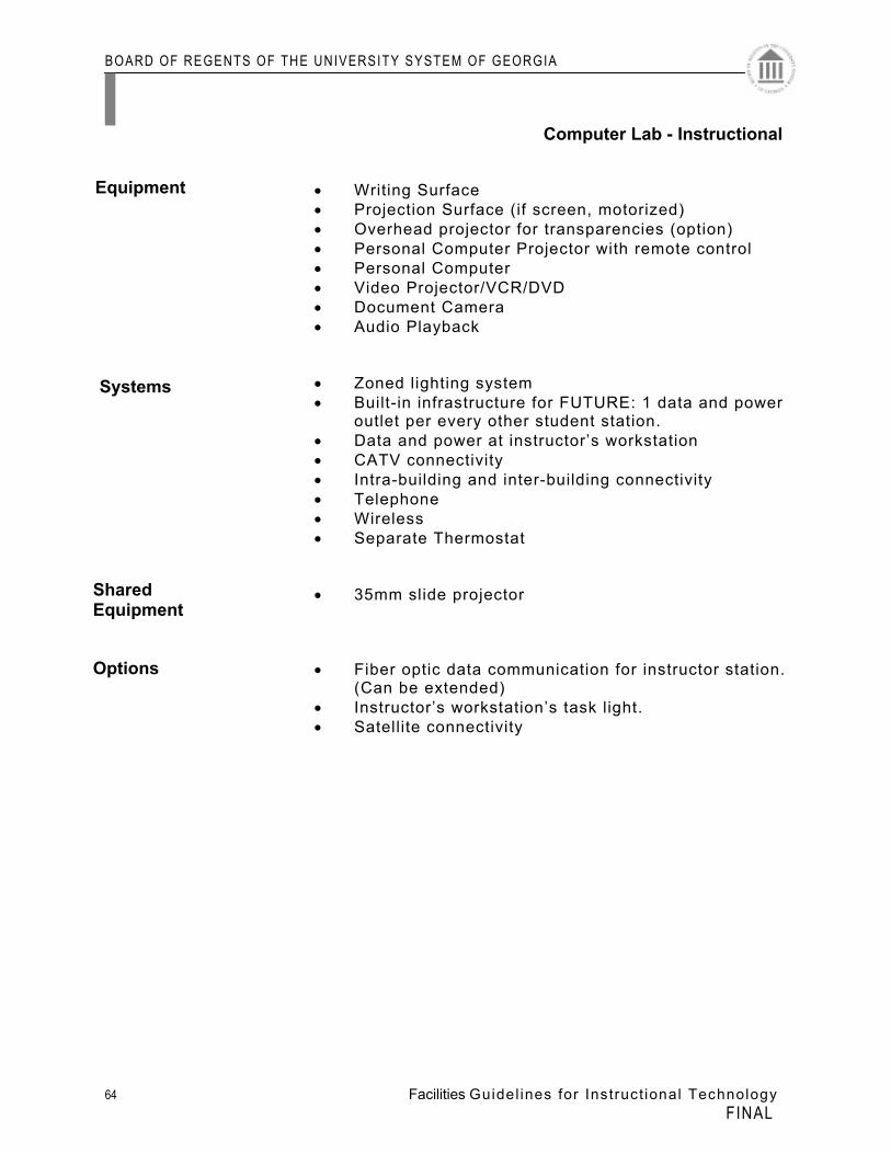
• Writing Surface • Projection Surface (if screen, motorized) • Overhead projector for transparencies (option) • Personal Computer Projector with remote control • Personal Computer • Video Projector/VCR/DVD • Document Camera • Audio Playback • Zoned lighting system • Built-in infrastructure for FUTURE: 1 data and power
outlet per every other student station. • Data and power at instructor’s workstation • CATV connectivity • Intra-building and inter-building connectivity • Telephone • Wireless • Separate Thermostat • 35mm slide projector • Fiber optic data communication for instructor station.
(Can be extended) • Instructor’s workstation’s task light. • Satellite connectivity
Systems
Shared Equipment
Options
Equipment
Computer Lab - Instructional
BOARD OF REGENTS OF THE UNIVERSITY SYSTEM OF GEORGIA
65 Facilities Guidel ines for Instruct ional Technology FINAL
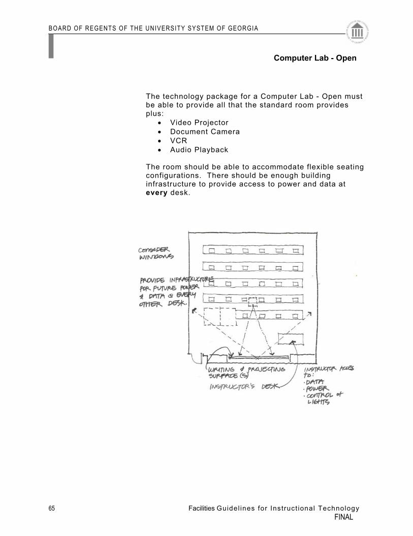
The technology package for a Computer Lab - Open must be able to provide all that the standard room provides plus:
• Video Projector • Document Camera • VCR • Audio Playback
The room should be able to accommodate flexible seating configurations. There should be enough building infrastructure to provide access to power and data at every desk.
Computer Lab - Open
Could be open for use ‘after hours’
BOARD OF REGENTS OF THE UNIVERSITY SYSTEM OF GEORGIA
66 Facilities Guidel ines for Instruct ional Technology FINAL
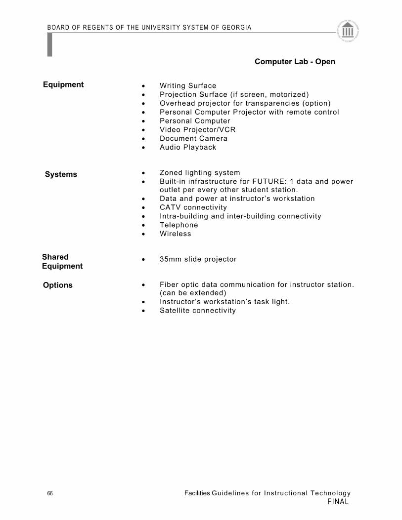
• Writing Surface • Projection Surface (if screen, motorized) • Overhead projector for transparencies (option) • Personal Computer Projector with remote control • Personal Computer • Video Projector/VCR • Document Camera • Audio Playback • Zoned lighting system • Built-in infrastructure for FUTURE: 1 data and power outlet per every other student station. • Data and power at instructor’s workstation • CATV connectivity • Intra-building and inter-building connectivity • Telephone • Wireless • 35mm slide projector • Fiber optic data communication for instructor station.
(can be extended) • Instructor’s workstation’s task light. • Satellite connectivity
Systems
Shared Equipment
Options
Equipment
Computer Lab - Open
BOARD OF REGENTS OF THE UNIVERSITY SYSTEM OF GEORGIA
67 Facilities Guidel ines for Instruct ional Technology FINAL
Office Spaces Office spaces should be designed such that there is
connectivity between offices and related service-support spaces, including conference rooms, work rooms, copy rooms and spaces for electronic support equipment. Faculty offices should be provided on the basis of one office per full-time equivalent faculty position. The arrangement of administrative offices, for the presidents, vice-presidents and the respective administrative staff should be designed to support the particular administrative organizational style best suited to the campus and its educational purpose. Whenever possible offices should be designed to incorporate the use of natural light.
Other consideration:
• Closed circuit TV access

BOARD OF REGENTS OF THE UNIVERSITY SYSTEM OF GEORGIA
68 Facilities Guidel ines for Instruct ional Technology FINAL
BLANK
BOARD OF REGENTS OF THE UNIVERSITY SYSTEM OF GEORGIA
69 Facilities Guidel ines for Instruct ional Technology FINAL
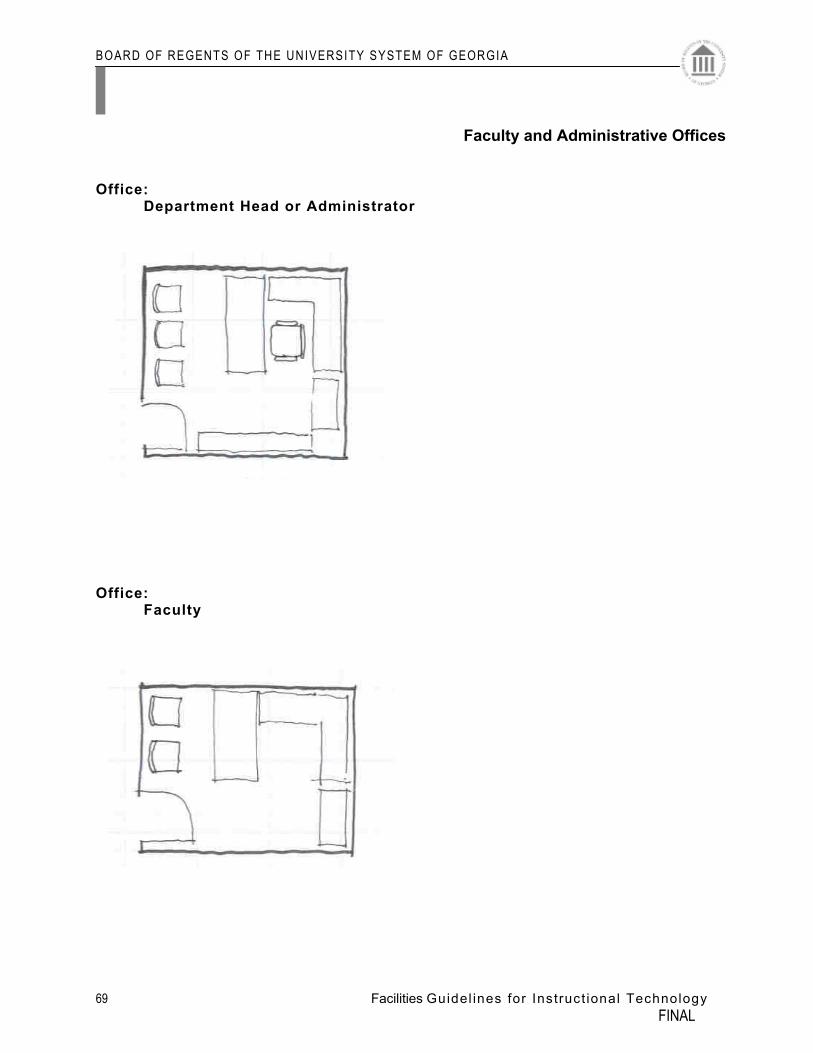
Office: Department Head or Administrator
Office: Faculty
Faculty and Administrative Offices
BOARD OF REGENTS OF THE UNIVERSITY SYSTEM OF GEORGIA
70 Facilities Guidel ines for Instruct ional Technology FINAL
• Personal computer at all stations • Data (voice and video) and power on all four walls of closed
offices.
Equipment
Systems
Faculty and Administrative Offices
BOARD OF REGENTS OF THE UNIVERSITY SYSTEM OF GEORGIA
71 Facilities Guidel ines for Instruct ional Technology FINAL
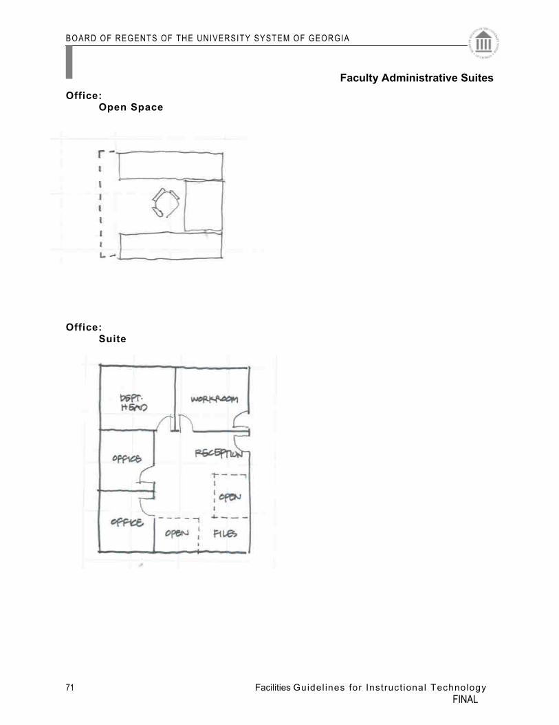
Office: Open Space
Office: Suite
Faculty Administrative Suites
BOARD OF REGENTS OF THE UNIVERSITY SYSTEM OF GEORGIA
72 Facilities Guidel ines for Instruct ional Technology FINAL
• Personal computer at all stations • Data and power on all four walls of closed offices. • Two data and ‘quad’ power per open station. • Data and power as required per equipment in workroom.
Provide outlets on all four walls of the workroom.
Equipment
Systems
Faculty Administrative Suites
BOARD OF REGENTS OF THE UNIVERSITY SYSTEM OF GEORGIA
73 Facilities Guidel ines for Instruct ional Technology FINAL
Informal Collaborative Collaborative spaces should be designed such that there is connectivity between related service-support spaces, including conference rooms, work rooms, copy rooms and spaces for electronic support equipment.
BOARD OF REGENTS OF THE UNIVERSITY SYSTEM OF GEORGIA
74 Facilities Guidel ines for Instruct ional Technology FINAL
BLANK
BOARD OF REGENTS OF THE UNIVERSITY SYSTEM OF GEORGIA
75 Facilities Guidel ines for Instruct ional Technology FINAL
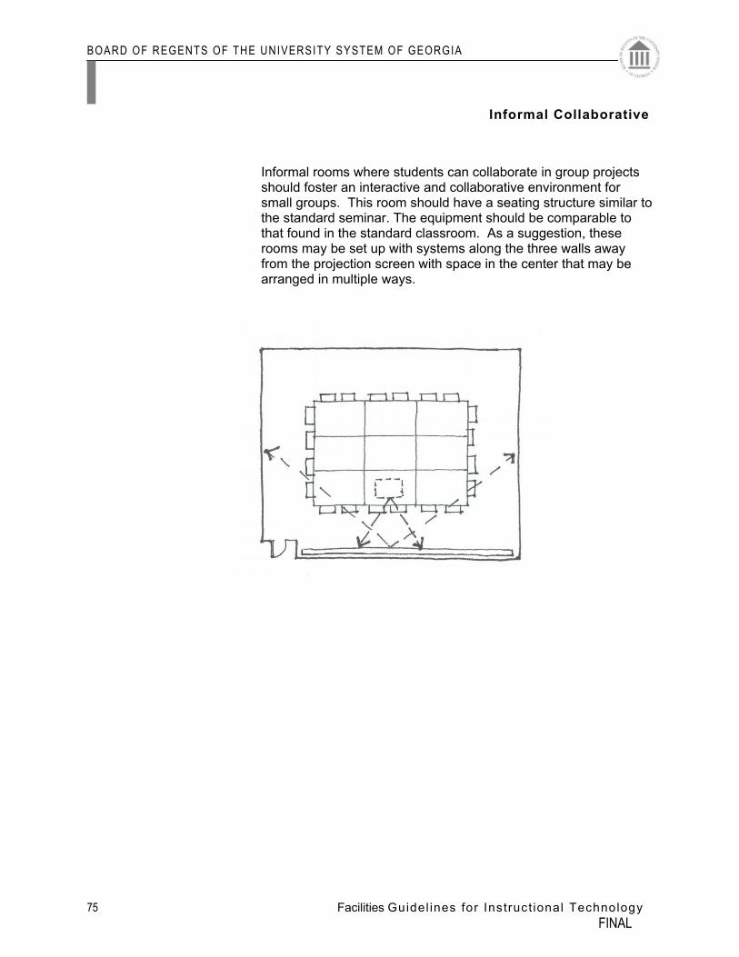
Informal rooms where students can collaborate in group projects should foster an interactive and collaborative environment for small groups. This room should have a seating structure similar to
the standard seminar. The equipment should be comparable to that found in the standard classroom. As a suggestion, these rooms may be set up with systems along the three walls away from the projection screen with space in the center that may be arranged in multiple ways.
Informal Collaborative
BOARD OF REGENTS OF THE UNIVERSITY SYSTEM OF GEORGIA
76 Facilities Guidel ines for Instruct ional Technology FINAL
• Writing Surface • Projection Surface (If screen manual) • Zoned lighting system • 35mm slide projector • Personal Computer Projector • TV/VCR
Informal Collaborative
Systems
Shared Equipment
Options
Equipment
BOARD OF REGENTS OF THE UNIVERSITY SYSTEM OF GEORGIA
77 Facilities Guidel ines for Instruct ional Technology FINAL
A access point (AP) The central or control point in a wireless cell that acts as a bridge for traffic to and from wireless devices in the cell. The AP also connects wireless devices to the wired portion of the LAN. American Society of Heating, Refrigerating, and Air-Conditioning Engineers (ASHRAE) An international society organized for the sole purpose of advancing the arts and sciences of heating, ventilating, air conditioning, and refrigerating for the public’s benefit through research, standard writing, continuing education and publications. Americans with Disabilities Act (ADA) U.S. Department of Justice regulations and guidelines under civil rights law that ensure individuals with disabilities have access to, or may use, public entities and government buildings. B Backboard A panel (e.g. wood or metal) used for mounting connecting hardware and equipment. backbone* A facility (e.g., pathway, cable, or conductors) between telecommunications rooms, or floor distribution terminals, the entrance facilities, and the equipment rooms within or between buildings. Board of Regents (BoR) C cable (CA) An assembly of one or more insulated conductors or optical fibers within an developing sheath, constructed to permit use of the conductors or optical fibers singly or in groups. See aerial cable; direct-buried cable; hard-sheath cable; underground cable. cable rack. The vertical or horizontal open support structure (usually made of aluminum or steel) that is attached to a ceiling or wall. campus The buildings and grounds of a complex, such as college, university, industrial park, or military base having legal contiguous interconnection. card reader See badge reader. central office (CO) A place where an access provider terminates customer lines and the switching equipment that interconnects lines. closed circuit television (CCTV) A private television system typically used for security purposes. coaxial cable An unbalanced cable consisting of a central metallic core surrounded by a layer of insulating material. This insulating (dielectric) material may be a sold material or air spaced. The entire assembly is covered with a metallic mesh or
ABBREVIATED GLOSSARY
BOARD OF REGENTS OF THE UNIVERSITY SYSTEM OF GEORGIA
78 Facilities Guidel ines for Instruct ional Technology FINAL
solid metallic sleeve and protected by an outer layer of non-conducting material (cable jacket). Conduit A rigid or flexible metallic or non-metallic raceway of circular cross-section through which cables can be pulled. Duct 1. Single enclosed pathway for conductors or cables, usually placed in soil or concrete. 2. An enclosure in which air is moved. Generally part of the heating, ventilating, and air conditioning system of a building. E Easement A right acquired by one party to use lands belonging to another party for a specific purpose. emergency power A stand-alone secondary electrical supply source that is activated when service from the primary electrical source is interrupted. equipment closet (EC) See telecommunications room. equipment room (ER) (telecommunications) A centralized space for telecommunications equipment that serves the occupants of a building. Equipment housed therein is considered distinct from a telecommunications room because of its nature or complexity. F Federal Communications Commission (FCC) Regulatory body of U.S. interstate telecommunications services and international service originating in the United States. Fiber Thin filament of glass or plastic that conducts a light signal. See optical fiber and plastic optical fiber (POF). fiber optics Optical technology concerned with the transmission of radiant light through fibers made of transparent materials such as glass, fused (vitreous) silica, or plastic. fireproof A property of a material such as masonry, block, brick, concrete, and gypsum board that does not support combustion even under accelerated conditions. No material is entirely fireproof. G Gateway The interconnection between two networks with different communications protocols. Gateways normally operate at one or more of the top four layers of the Open Systems Interconnection Reference Model. H hertz (Hz) A unit frequency equal to one cycle per second. home run A pathway or cable between two locations without a splice or intermediate termination points in between. horizontal cabling The cabling between and including the work area telecommunications outlet/connector and the horizontal cross-connect (floor distributor) in the telecommunications room.
BOARD OF REGENTS OF THE UNIVERSITY SYSTEM OF GEORGIA
79 Facilities Guidel ines for Instruct ional Technology FINAL
Hub A network device that provides a centralized point for LAN communications, media connections, and management activities of a physical star topology cabling system. It is used to control and direct the flow of data through a structured cabling network.
I Infrastructure Permanently installed cable plant.
inter-building (campus) backbone A backbone network providing communications between more than one building. Internet A worldwide network of computers (servers) that links the user to businesses, government agencies, universities, and individuals. intra-building backbone A backbone network providing communications within a building. Intranet A collection of Internet-based technologies designed to provide content to users on an internal network. The content is viewed using a Web browser. J Jack See modular jack. K kilowatt (kW) A unit of electrical power equal to 1000 watts. L ladder rack A device similar to a cable tray but more closely resembles a single section of a ladder. It is constructed of metal with two sides affixed to horizontal cross members. local area network (LAN) A geographically limited data communications system for a specific user group consisting fo a group of interconnected computers sharing applications, data, and peripheral devices such as printers and CD-ROM drives intended for the local transport of data, video, and voice. M main terminal room See main terminal space.
Master Plan for Information and Instructional Technologies megahertz (MHz) A unit of frequency equal to one million cycles per second (hertz). multiple access In satellite communications satellite from a number of ground stations. N National Fire Protection Association (NFPA ®) Association that writes and administers the National Electrical Code ® (NEC ®).
BOARD OF REGENTS OF THE UNIVERSITY SYSTEM OF GEORGIA
80 Facilities Guidel ines for Instruct ional Technology FINAL
O open office An area of floor space with division provided by furniture, movable partitions, or other temporary means instead of by building walls. optical fiber cable Cable made up of one or more strands of optical fibers, strength members, and an outer jacket. P Penetration Opening made in fire-rated barrier (architectural structure or assembly). 1) There are two kinds of penetrations: Membrane pierces or interrupts the outside surface of only one side of a fire-rated barrier. 2) Through penetration completely transmits a fire-rated barrier, piercing both outside surfaces of the barrier. plenum* A compartment or chamber to which one or more air ducts are connected that forms part of the air distribution system. Because it is part of the air distribution system, cables installed in this space require a higher fire rating. 2000 Pre-Planning Guidelines R Raceway Any enclosed channel designed for holding wires, cables, or busbars. request for quotation (RFQ) A document that solicits quotes for telecommunications projects for equipment and provides vendors with all the information necessary to prepare a quote. S Scalability The ability of a network to grow with degradation of quality. Security Protection against unauthorized activities, generally requiring a combination of access controls, data integrity, and transaction confidentiality. Server A network device that combines hardware and software to provide and manage shared services and resources on the network. T Telecommunications A branch of technology concerned with the transmission, emission, and reception of signs, signals, writing, images, and sounds; that is, information of any nature by cable, radio, optical, or other electromagnetic systems. telecommunications outlet (TO)* See outlet/connector (telecommunications). telecommunications room (TR) An enclosed space for housing telecommunications equipment, cable terminations, and cross-connects. The room is the recognized cross-connect between the backbone cable and horizontal cabling.
BOARD OF REGENTS OF THE UNIVERSITY SYSTEM OF GEORGIA
81 Facilities Guidel ines for Instruct ional Technology FINAL
terminal (TERM) 1. A point at which information may enter or leave a telecommunications network. 2. The input-output associated equipment. 3. A device that connects wires to each other. trunk cable The term trunk refers to the main distribution cable. A typical trunk begins at the head-end and terminates at the outermost feeder cable. U University System of Georgia (USG) V variable air volume (VAV) A self-contained heating, ventilating, and air-conditioning (HVAC) unit that uses a built-in microprocessor-based controller to control environmental air to a specific zone via a damper. The unit is placed near the end of a HVAC duct and can also monitor temperature inputs from local sensors. W wavelength The length of a wave measured from any point on one wave to the corresponding point on the next wave, such as from crest to crest. The wavelength of light is usually measured in nanometers (nm). Web Used as a noun, it is shorthand for the World Wide Web (www) services found on the Internet. wiring closet See telecommunications room. workstation A telecommunications device used in communicating with another telecommunications device. References: 1) TDM Manual on CD-ROM, 9th edition © 2000 BICSI ® 2)* Terms marked with an asterisk are reprinted with permission of Telecommunications Industry Association (TIA). Complete copies of All TIA standards can be purchased through Global Engineering Documents at 800- 854-7179 or 303-397-7956.
BOARD OF REGENTS OF THE UNIVERSITY SYSTEM OF GEORGIA
82 Facilities Guidel ines for Instruct ional Technology FINAL
BLANK
BOARD OF REGENTS OF THE UNIVERSITY SYSTEM OF GEORGIA
79 Facilities Guidel ines for Instruct ional Technology FINAL
APPENDIX
The following appendices were generated by the Subcommittees of the Technology Task Force and are based on raw data provided.

BOARD OF REGENTS OF THE UNIVERSITY SYSTEM OF GEORGIA
80 Facilities Guidel ines for Instruct ional Technology FINAL
BOARD OF REGENTS OF THE UNIVERSITY SYSTEM OF GEORGIA
81 Facilities Guidel ines for Instruct ional Technology FINAL
Descriptions 1. A strategic direction as regards data communications
For most USG campuses should be to consider the campus wireless networking “radio space” to be part of a mandate to provide campus wide network management, reliability and service. As such, just as the wired network infrastructure on a campus, no departments or schools should install their own wireless infrastructure or “do their own thing” without fully coordinating with a central technology authority.
Discussion 2. Even more so than with network technology, 802.11
wireless networking has a multitude of areas that can “step on” or conflict with campus provided services in this arena. Channel allocations, device placement, configuration of the Wireless Network Name or SSID all have the potential to disrupt a critical campus service. Unlike switched/wired networking, wireless technology requires one to design networks in three dimensions (sometimes more).
In that regard, a campus standard vendor for 802.11
wireless networking should probably be chosen to obtain a product line with as much compatibility as possible. Once chosen, from that point in time, other vendor brands of wireless network equipment must not ‘show-up’ on campus!
Once the vendor and products are chosen, the
campus should develop a Web page with documentation on support for these wireless adapters and a map indicating the priorities for coverage areas on campus.
Also, it is important to keep in mind that at the present
time, the current implementation of wireless networking is a technology with a very short life span. This current technology provides a SHARED bandwidth of 11 Mb/sec per access point; in the near future, this will be 22 Mb/sec. In the not too distant future, it will be 54 Mb/sec. It therefore makes no sense in the year 2001 to fully outfit a campus with appropriate coverage – campuses that are doing that now are throwing away precious technology funds. A campus should, however, look at priority locations in terms of where they deploy access points today. Note also the wireless technology is and will continue to be
APPENDIX
Wireless
BOARD OF REGENTS OF THE UNIVERSITY SYSTEM OF GEORGIA
82 Facilities Guidel ines for Instruct ional Technology FINAL
a SHARED bandwidth technology (like old 10BaseT hubs). As such, technologies that rely on appropriately configured switching electronics, like IP multicast, will not effectively work in the wireless environment.
The following Wireless Standard from Georgia State University provides the reader some additional thoughts related to this technology:
“Wireless access at Georgia State University is a convenience service limited to satisfying requirements for linking portable (untethered) or dislocated computers into the campus LAN structure. Wireless is not a direct replacement for standard cabled connection of desktops/laptops/notebooks and peripherals to the campus infrastructure. Wireless systems at Georgia State University will not be engineered or configured to support continuous coverage of roaming users across the campus. As a convenience service, users must be aware that problem resolution for connection over wireless may not be resolved as quickly as desired. Users of wireless access will have their wireless card and devices registered with UCCS before access can be obtained through any campus registered and operated access port. The capacity of wireless connectivity is limited by both bandwidth and distance. Users must be aware that connection will not be guaranteed and that once connected, links are subject to interruption or degradation by interference from other electronic devices, building structure or weather conditions. The University only supports over the air technology governed by IEEE standard 802.11b and will util ize only equipment that as a minimum has been certified interoperable by Wireless Ethernet Compatibility Alliance (WECA). UCCS will publish a listing of equipment vendors and models that have been tested in the Georgia State University environment and found to be compatible. Users may ask UCCS to conduct certification on other equipment on a time available basis. Wireless access will be provided in two varieties at Georgia State University. Public Access. Public Access shall be construed to mean unsecured access ports installed in public areas such as the Library, Campus Plaza, Student Center or other public areas intended for general public use. Public zone identification
BOARD OF REGENTS OF THE UNIVERSITY SYSTEM OF GEORGIA
83 Facilities Guidel ines for Instruct ional Technology FINAL
keys will be published to the campus population. Communication links will not be encrypted. Access may be restricted to selected services. Public Access systems will not be used to host servers; however users entering the network through a Public Access would be able to use servers hosted on the cabled infrastructure. All Wireless systems whether Public or Private will be registered with UCCS. As a minimum UCCS will retain information on frequency assignment, physical location, zone key and responsible department contact. New wireless systems must be reviewed by UCCS before purchase or implementation. Registration of wireless user devices will be centrally managed by UCCS. Frequency allocation will be managed by UCCS to ensure recommended industry separation. Wireless hubs that are interfering with property registers production hubs will be disconnected until the device can be setup in a non-interfering configuration.”
BOARD OF REGENTS OF THE UNIVERSITY SYSTEM OF GEORGIA
84 Facilities Guidel ines for Instruct ional Technology FINAL
BOARD OF REGENTS OF THE UNIVERSITY SYSTEM OF GEORGIA
85 Facilities Guidel ines for Instruct ional Technology FINAL
USG approved enrollment targets (approved annually through the Office of Academic & Fiscal Affairs
USG Building Project Procedures and Design Criteria USG Environmental Evaluations for Projects within the University System of Georgia USG Facilities, Curriculum and Room Utilization Annual Summary USG Faculty Information Report USG Information Digest and Fact Book USG Institutional Strategic Planning Guidelines USG Instructions for Preparation of Five-Year Capital Outlay Funding Requests USG Physical Master Planning Template Reference Guide USG Principles for Capital Resources Allocation USG Real Property Inventory System (institution data) USG Comprehensive Plan USG Environmental Health and Safety Policy
APPENDIX
USG Guidelines/ Requirements/ Resources
BOARD OF REGENTS OF THE UNIVERSITY SYSTEM OF GEORGIA
86 Facilities Guidel ines for Instruct ional Technology FINAL
BOARD OF REGENTS OF THE UNIVERSITY SYSTEM OF GEORGIA
87 Facilities Guidel ines for Instruct ional Technology FINAL
1. Cabling & Wiring 1.1 Multimode Optical Fiber Cable The two recommended multimode fiber cables are graded- index optical fiber with a nominal 62.5/ 125 µm or 50/ 125 µm core/ cladding diameter. (Caution: DO NOT mix 62.5 and 50 µm core fiber) The fiber should conform to the following standards or international equivalents:
ANSI/ TIA/ EIA- 568- B (overall requirements) ANSI/ TIA/ EIA- 492AAAA (62.5/ 125 µm fiber specifications) ANSI/ TIA/ EIA- 492AAAB (50/ 125 µm fiber specifications) ANSI/ ICEA S- 83- 596 (indoor optical cables) ANSI/ ICEA S- 87- 640 (outdoor optical cables)
1.2 Singlemode Optical Fiber Cable The recommended cable is Class IVa Dispersion unshifted singlemode optical fiber. It should conform to the following standards or international equivalents:
ANSI/ TIA/ EIA- 568- B (overall requirements) ANSI/ TIA/ EIA- 492CAAA (fiber specifications) ANSI/ ICEA S- 83- 596 (indoor optical cables) ANSI/ ICEA S- 87- 640 (outdoor optical cables)
1.3 100 ohm Twisted- Pair The recommended twisted- pair cable consists of 24 AWG [0.51 mm (0.020 in)] or up to 22 AWG [0.64 mm (0.025 in)] round solid copper conductors with a nominal characteristic impedance of 100 . This cable must conform to the following standards or international equivalents:
ANSI/ TIA/ EIA- 568- B and addenda 1 ICEA Publication S- 80- 576 (cable specifications) ASTM D4566 (performance measurements)
1.4 Performance Categories for Backbone Twisted- Pair Backbone twisted- pair cable is specified in performance categories. The categories are:
Category 3 (specified up to 16 MHz). Category 5e (specified up to 100 MHz).
NOTE: Category 6 requirements are under study by TIA TR 42.7/558 and are subject to replace 5e as the recommended cabling at the time of this writing. 2.0 Building 2.1 Elevator Shafts Do not locate backbone cable pathways in elevator shafts. 3.0 Fiber
APPENDIX
Intra-building/ Inter-building Related Topics
BOARD OF REGENTS OF THE UNIVERSITY SYSTEM OF GEORGIA
88 Facilities Guidel ines for Instruct ional Technology FINAL
3.1 Fiber Optic Cable Markings The following table summarizes Table 770- 50 of the NEC.
Optical Cable Marking Type OFNP Non- conductive plenum OFCP Conductive plenum OFNR Non- conductive riser OFCR Conductive riser OFN, OFNG Non- conductive OFC, OFCG Conductive
3.2 Duplex SC Connector ANSI/ TIA/ EIA- 568- B, Commercial Building Telecommunications Cabling Standard, and ISO/ IEC 11801 recommends for fiber, the duplex SC connector interface to be used at all cross- connects and outlets in the premises environment. Additionally, a number of application standards have standardized on the duplex SC, such as low- cost FDDI, Fiber Channel, 1 giga bit & 10 giga bit ethernet broadband integrated services digital network (ISDN), and asynchronous transfer mode (ATM). The ANSI/ TIA/ EIA- 568- A standard does “grandfather” the existing installed base of ST- compatible connectors. The primary advantages of the duplex SC connector are:
It is a duplex connector, which allows for the management of polarity. It has been recommended by a large number of standards. Most SC connectors offer a pull- proof feature for patch cords.
3.3 Migration Path for ST- Compatible Users Because of the large number of users with an installed base of ST- compatible connectors, the ANSI/ TIA/ EIA- 568- A and ISO/ IEC 11801 specifications recognize a number of viable options for these users. They:
Remain with ST- compatible simplex connectors for both future and existing networks.
Retrofit existing networks by using a hybrid adapter of duplex SC to ST- compatible.
Switch to the duplex SC interface for both future and/ or existing networks. Note many manufactures are placing small form factor connectors on their equipment because they can reduce the equipment cost. It is NOT recommended to terminate fiber for inter – intra backbones with small form factor connectors. The life span of these connectors has not been determined and could represent a substantial cost to change later.
3.4 Fiber- to- the- Desk Requirements Fiber- to- the- desk applications may require backbone extension from the horizontal fiber. In these cases, the number of fibers in the backbone will usually match the total number of horizontal fibers. In some cases, horizontal fibers may be extended through backbone pathways. However, this may not be possible because the horizontal cables:
May need to be rated for riser use (in some areas). Can take up too much space in the backbone pathway.
Patch panels are recommended at termination points. The number of links terminated determines the patch panel requirements. Additional space should be allocated to patch panels so growth after installation can occur gracefully.
BOARD OF REGENTS OF THE UNIVERSITY SYSTEM OF GEORGIA
89 Facilities Guidel ines for Instruct ional Technology FINAL
The designer/ installer should use patch panels at IDR and cross- connect locations, such as: Main entrance room Intermediate data room Horizontal cross- connects (HCs [floor distributors (FDs)]).
4.0 Cable Types: Always follow the original equipment manufacturer (OEM) electronic equipment specifications for optical fiber core size when designing an optical fiber telecommunications system. Contact the OEM if:
Specifications vary from the 62.5/ 125 µm or 50/ 125 µm multimode standard. The fiber is used for a unique application.
4.1 Interbuilding (Campus) Backbone The following distance limitation specifications are provided to ensure that the backbone can accommodate voice and data transmission applications. These specifications do not necessarily apply to backbones designed solely for telephone and low- speed data. The designer must verify support for media and distance with the suppliers of applications equipment. From Horizontal the length of transmission cable between the equipment and the workstation or equipment should not exceed
500m (1640 ft) for multi mode fiber for giga-bit speeds. 2000m (6562 ft) for multi mode fiber for up to 155 mega bit/sec speeds 3000m (9843 ft) for single mode fiber for up to 10 gigabit/sec speeds 800m (2625 ft) for ANSI/TIA/EIA 568 B 100 ohm systems for low speed applications.
Note: The total horizontal length is limited by the standard to 90m (295 ft) regardless of the media. 4.2 Determining Requirements Treat a campus backbone system as one project for telecommunications purposes. For each building, follow the basic requirements:
Individual service entrances. Termination space. Backbones. Horizontal distribution support structures. Equipment rooms (ERs). Telecommunications rooms (TRs). Data services. Video services. Transmission. Outside plant (OSP).
Power distribution. Safety measures such as:
– Bonding. – Grounding. – Electrical protection.
BOARD OF REGENTS OF THE UNIVERSITY SYSTEM OF GEORGIA
90 Facilities Guidel ines for Instruct ional Technology FINAL
– Building codes and regulations. – Firestopping.
4.3 Main Entrance Cable Guidelines OSP cables are typically unlisted because of the sheath material and filling compounds used within the cables. In the United States, the NEC allows the use of exposed OSP cable for the first 15.2 m (50.0 ft) at the building entrance. OSP cables routed inside a building are influenced by fire codes. Often a choice must be made between:
• Planning a splice point at the building entrance to transition from outdoor non- listed to indoor listed cable designs. The added loss of the splice is small and usually not significant in the link loss budget, or • Either enclosing conductive outdoor cables in rigid or intermediate conduit that is properly grounded, or running non- conductive outdoor cables in a raceway.
Underground facilities are cables placed in subsurface conduits, using maintenance holes (MHs) and/ or pull boxes. Splices may be used in MHs for telephone systems only. Splices for fiber systems are prohibited in manholes. Underground pathways use conduit to provide out- of- sight facilities. The conduit:
Is usually provided by the building owner. Runs between building entrance locations and also to a pole, pedestal, or MH.
The advantages of underground conduit are that they: Preserve the aesthetic appearance of the premises. Are adaptable for future facility placement or removal. Are economical over a long life. Provide the security of additional physical cable protection. Minimize the need for possible subsequent repairs to the property when growth is required for existing facilities.
Direct- buried facilities are cables placed directly in the earth. This is prohibited because of the high risk of damage and wastefulness of financial resources. This will only be allowed as a short term temporary means of providing a work around for certain situations such as phased construction. Aerial pathways are another means of supporting interbuilding cabling. The advantages of aerial pathways are that they:
Usually can be installed quickly. Are readily accessible for maintenance.
The disadvantages of aerial pathways are that they:
Affect the aesthetic appearance of the property. Are subject to traffic and pedestrian clearances. Can damage building exterior. Are susceptible to environmental conditions, such as falling tree limbs and lightning.
5.0 Outside Plant
BOARD OF REGENTS OF THE UNIVERSITY SYSTEM OF GEORGIA
91 Facilities Guidel ines for Instruct ional Technology FINAL
5.1 Trench Depth The minimum depth of a trench should allow 600 mm (24 in) of cover from the top of the cable to final grade. 5.2 Locating and Identifying Subsurface Facilities
Identify all subsurface facilities (e. g., power, gas, water, outdoor lighting, etc.) before trenching to avoid damaging them while trenching for a buried cable. Always call the local underground utilities call center before digging. Required install a #6 ground wire along conduit path terminate and ground in each handhold and pull box and terminate before entrance of any building with a 8 ft deep ground rod. This is used to bleed off static charges and to provide a signal path to locate non-metallic systems.
5.3 Warning Tape/Cable Requirements To minimize any chance of an accidental dig- up, place plastic warning tape a minimum of 450 mm (18 in) above the cable. Warning tape is either:
Non- detectable, (e. g., containing no metallic elements). Detectable, (e. g., containing metallic tracings).
The American Public Works Association has adopted the color orange for telecommunications and CATV cables. 5.4 Conduit Guidelines 1- Regulating Bends
All bends must be long, sweeping bends with a radius not less than: Six times the internal diameter of conduits 50 mm (2 in) or smaller, or Ten times the internal diameter of conduits larger than 50 mm (2 in). Reaming Conduit All ends of metallic conduit must be reamed. All protruding ends must be fitted with bushings at both ends.
2- Preventing Conduit Shearing
Such backfill is susceptible to load- bearing tension. Metal sleeves through walls must extend to undisturbed earth to prevent shearing, particularly where
3- Minimum Depth Top of conduit must be buried at least 600 mm (24 in) below the ground surface. NOTE: In areas where frost conditions could damage cables in conduit, greater burial depth may be desirable.
4- Encasement
Consider encasing conduit, particularly polyvinyl chloride (PVC), in concrete when: Minimum conduit depth cannot be attained. Conduits pass under roads, driveways, or railroad tracks. Bend points might be subject to movement. Consider using rebar (reinforcing bars) within the concrete at any location subject to potentially extreme stress. Avoiding Joint- Use Maintenance Holes (MHs)
Do not terminate conduit placed on private property in joint- use MHs with electrical cables. Although local or national codes may permit this (under special conditions), a separate MH and MH entry must be provided for telecommunications facilities to ensure the safety of all personnel.
BOARD OF REGENTS OF THE UNIVERSITY SYSTEM OF GEORGIA
92 Facilities Guidel ines for Instruct ional Technology FINAL
5- Conduit Entry Points The general recommendation is to place conduit entry points at opposite ends of a MH or pull box, instead of through the sidewalls. While placing the conduit entry points at opposite ends may require an additional conduit sweep, it provides the following benefits:
Allows neater cable formation in the MH/ pull box Maximizes the available working space at the center of the MH/ pull box Permits splaying (offset closer to the side walls) the entry points in certain situations
6- Identifying Covers
Mark all telecommunications MH or pull box covers for easy identification. Mark covers with:
“Communications” 7- Maintenance Hole (MH) Interior Hardware
All hardware in MHs must be galvanized. MHs should be equipped with: Bonding inserts and struts for racking. Pulling eyes at least 22 mm (7/ 8 in) in diameter. A sump of at least 200 mm (8 in) in diameter. An entry ladder (where feasible).
8- Placing Innerducts
Where optical fiber cables will be used, consider placing three innerducts (two 38 mm and one 25 mm [two 1.5 in and one 1 in]) inside each 103 mm (4 trade size) conduit designated for this purpose to ensure physical cable protection. An innerduct is a smaller pathway within the conduit available in:
Various diameters (typically 25- 50 mm [1- 2 in]). Various reel lengths. Short sections.
Each innerduct should be equipped with a pull device. Channelized innerducts compartmentalized into separate sections are also available.
5.5 Cable Placement Planning and Design Factors In any MH system, the MHs must be:
Sized to meet the maximum conduit requirements. Located to optimize the use of the associated conduit routes.
Use pre- cast MHs wherever possible for uniformity, economy, and installation efficiency. Use site- cast MHs whenever:
BOARD OF REGENTS OF THE UNIVERSITY SYSTEM OF GEORGIA
93 Facilities Guidel ines for Instruct ional Technology FINAL
The size required exceeds pre- cast sizes. Obstructions prohibit placing pre- cast MHs. MH must be rebuilt. A custom design is required.
In any MH system, seal all conduits to prevent water entry. 5.6 Aerial Plant Criteria Planning and Designing Guidelines The following are suggested planning and designing guidelines for aerial plant:
Consider aerial design if buried design is significantly more expensive or is not feasible due to temporary area construction.
Select permanent locations for pole lines while considering: – Future road widening or realignment. – Expansion of other utilities. – Special problems such as road, railway, and power line crossings. – Safety and convenience of workers and the general public. Design pole line for ultimate needs, considering:
– Pole line classification. – Storm loading. – Clearance requirements.

BOARD OF REGENTS OF THE UNIVERSITY SYSTEM OF GEORGIA
94 Facilities Guidel ines for Instruct ional Technology FINAL
BOARD OF REGENTS OF THE UNIVERSITY SYSTEM OF GEORGIA
95 Facilities Guidel ines for Instruct ional Technology FINAL
Elements of a Cable System A typical cable system consists of three basic elements:
Headend— An equipment room that contains the electronics for receiving and processing TV programs. The output of the headend connects to the distribution system.
Distribution System— A network of distribution media such as coax or fiber optic cables, amplifiers, and passive devices such as couplers and splitters.
Room/location Drop— The taps, cable, and outlet where the users connect the TV set. The room/location drop is connected to the distribution system at the tap normally in the telecommunications room on each floor.
System Topologies There are three basic topologies used in private CATV distribution systems. Most systems are actually designed with a combination of these basic topologies:
Home run Trunk- and- branch Loop- thru
Home Run Design The home run design uses a run from a WA outlet in each room to a central telecommunications room (TR). This TR is connected to a trunk cable from the headend. In a small system, the TR may be the headend. A home run system includes an amplifier at the headend to boost the signal and a network of splitters or taps to distribute the signal to the home run cables. A home run design is normally only used in very small installations. In horizontal telecommunications wiring, this home run design is called a star topology. Trunk- and- Branch Design A trunk- and- branch design uses multiple trunk cables to distribute the signal to different geographical areas, such as on a campus or in a large building. In a campus system, a trunk cable will feed a building, with branch cables feeding each floor of the building. In horizontal telecommunications wiring, the trunk- and- branch design is called a hierarchical star topology. A coaxial cable consists of a solid or stranded inner conductor surrounded by a dielectric (i. e., insulating) material (usually a hard or soft foam polymer, depending upon the installation design specification and application). The dielectric material is wrapped with a continuous aluminum- polyester shield and tinned copper braid or other shielding configurations. The entire assembly is protected by a polyvinyl chloride (PVC) or National Fire Protection Association (NFPA ® )- approved fire- retardant cable jacket material. The most common types of coaxial cable used in intrabuilding CATV systems are:
RG59. RG6Q.(quadshield) RG11Q.(quadshield) PIII- 500.
APPENDIX
CATV Distribution System
BOARD OF REGENTS OF THE UNIVERSITY SYSTEM OF GEORGIA
96 Facilities Guidel ines for Instruct ional Technology FINAL
Coaxial cables installed in buildings must meet the same code requirements as telecommunications cables. Cable markings and identification are given to coaxial cable in much the same manner that telecommunications cables are identified. Cable Marking Type NEC Section Reference CATV CATV cable 820- 50 CATVP CATV plenum cable 820- 50 CATVR CATV riser cable 820- 50 CATVX CATV cable, limited use 820- 50 Signal Loss in the Network There are four factors that must be considered when calculating losses in designing a network: • Cable loss • Splitter loss • Insertion loss • Isolation loss Cable loss is calculated based on the distance that a signal must travel along with the lowest and highest frequency transmitted on the system. When calculating cable loss, consider the: • Cable manufacturer’s loss value, which is generally given as a dB value per 100 m (328 ft), or per 100 m (328 ft) at several frequencies. • Transmission frequency of the signal. Because losses are greater at higher frequencies, calculate the loss for the lowest and highest frequency that the system will deliver. This characteristic of coax cable is called cable tilt. Most cable loss values are based on a temperature of 20 °C (68 °F) and will vary slightly under different conditions. Like other current- carrying cables, CATV cables show increased resistance and loss at higher temperatures. However, it is usually safe to disregard temperature compensation calculations when dealing with intrabuilding systems. Insertion loss is a measure of the attenuation of a signal between the input and output of a passive device. The unit of measure for insertion loss is the dB. The insertion loss for directional couplers and tap- offs is determined by the tap value. The lower the tap value the higher the insertion loss. The insertion loss for a splitter is a direct function of the quantity of output ports. The higher the quantity of ports, the higher the insertion loss of each port. Isolation loss is loss associated with a tap. Each tap in a system reduces the signal from the trunk or feeder by a specific loss value, expressed in decibels. For example, if a tap with a loss of 15 dB is inserted into a feeder line carrying a 20 dB signal, the result would be an available signal of 5 dB. The insertion loss of the tap is one dB on the feeder and the isolation loss is 15 dB off the tap. Network Design The goal for the designer is to design a system that will provide a signal level between 3 dBmV and 10 dBmV to every outlet on all channels. Step Designing an Intrabuilding Private CATV Network
1. Obtain a copy of the facility blueprints.
BOARD OF REGENTS OF THE UNIVERSITY SYSTEM OF GEORGIA
97 Facilities Guidel ines for Instruct ional Technology FINAL
2. Determine the location of all WAs that will be equipped for CATV. 3. Identify the location of the headend. 4. Determine the system topology or combination. 5. Determine the appropriate fire rating for the coaxial cable sheath. Plan on installing conduit if the local building code requires it. 6. Decide on the routing of the trunk cables from the headend to each area to be served. Routing of the trunk cables should be such that taps can be centrally located within their serving area. It is common for multiple trunk cables to be used in a system. 7. Place all taps in the IDR. Taps typically serve from two to eight outlets. Unlike a traditional voice and data network, a CATV network in a private building seldom has
any moves, adds, changes (MAC) activity; therefore, ease of access for cross- connects is not a concern.
8. Determine the routing of the subscriber drop cables. 9. Type of coax that will be used for the drop cable. RG6Q for runs up to 200 feet and
RG11Q for runs from 200 to 300 ft 10. Calculate the loss of each subscriber drop that will attach to a tap. Unlike
telecommunications cables, the length of the coaxial cables has an impact on the distribution network design. The loss difference between the shortest and longest drop cables from a tap should be no more than 7 dB. This will provide the recommended signal level at the outlet of 3 dBmv to 10 dBmv. The loss should be calculated for the lowest channel and the highest channel planned for the system. The loss increases as the frequency of the signal increases.
11. Decide on the type of trunk cable that will be used. RG11 and PIII- 500 are common for
this purpose. PIII- 500 is generally used for longer distances because it has less loss than RG11. RG11 has a flexible sheath and PIII- 500 has a semi-rigid aluminum sheath. Both types of coax are available with a plenum rating.
12. Determine where directional couplers and splitters will be used in the system. Splitters
divide the signal into 2, 3, or 4 equal branches. Directional couplers take part of the signal from a trunk and feed it to a branch.
13. At some point in the network, it may be necessary to add an amplifier. A typical
amplifier will provide a gain of 35 dB. 14. The designer will need to compensate for cable tilt in most systems. This can be done
with the tilt control on the amplifier or with a separate device called an equalizer. 15. Adjustments and recalculations are very common, especially when splitters and
directional couplers are involved.
BOARD OF REGENTS OF THE UNIVERSITY SYSTEM OF GEORGIA
98 Facilities Guidel ines for Instruct ional Technology FINAL
Proof of performance testing involves two steps:
16. Aligning/ balancing the system. 17. Testing the system and its components.
Aligning and balancing the system involves adjusting the gain or sensitivity of the system’s amplifiers to match the specified signal levels in the system design. The system’s performance cannot be analyzed until this aligning and balancing is completed. The test equipment used should include signal level meters (SLMs) and time domain reflectometers (TDRs). The tests should ensure that the system and its components meet the specifications for:
18. Distortion. 19. Signal uniformity. 20. Signal- to- noise ratio (SNR). 21. Signal ingress. 22. Hum modulation.
Generally, impedance, time domain, and structural return loss tests are performed as a pre- installation check of the cable. Testing for distortion, signal uniformity, and SNR is performed on installed cable using a SLM unit. Final quality test should be preformed by providing a video signal from a VCR and viewing that signal with a color TV on the low band channels and the VHF channels.
BOARD OF REGENTS OF THE UNIVERSITY SYSTEM OF GEORGIA
99 Facilities Guidel ines for Instruct ional Technology FINAL
1. Electrical 1.1 Adequate Grounding The following are some considerations:
Make sure the equipment grounding conductor is electrically continuous back to the power source.
The equipment grounding conductor (green wire) should be the same size as, or larger than, the current- carrying conductors.
Conduit alone should not be relied upon to act as the equipment grounding conductor. Use the same grounding point connected in a star pattern (do not daisy chain) to the
individual branch circuits in the same system (e. g., the telephone switch and all ancillary equipment such as consoles, printers, channel equipment, etc., should have the same grounding point).
In the United States, become familiar with NEC Article 250, “Grounding”; Article 645, “Information Technology Equipment”; and Article 800, “Communications Circuits.” Chapter 8 of the NEC (which includes Article 800) covers communications systems and stands independent of the other NEC
chapters, except where they are specifically referenced. Never use a grounding electrode that is independent from the power system ground.
Always bond separately derived grounding systems to the building grounding electrode system.
Keep the equipment grounding conductor as short as possible, preferably less than 6 m (20 ft). This reduces impedance to ground at high frequencies.
A good grounding system must meet the requirements of the NEC, and must also be configured to minimize noise pickup.
The use of properly installed isolated ground (IG) receptacles is permitted by the NEC for the reduction of electrical noise in the grounding circuit. These receptacles are identified by their orange color or an orange triangle. Where used for such an application, and although not intended for the purpose, the receptacles can also serve as a useful deterrent against the connection of unauthorized loads.
1.2 Static Static electricity discharges to a conducting surface and causes equipment malfunctions because of induced noise impulses. Preventive measures include:
Using antistatic sprays and floor covering with a low propensity to static. Using static discharge plates and/ or jacks, and wrist straps for personnel. Maintain at least 30 percent relative humidity in the telephone or data processing room. Avoid the wearing of clothing that generates static, such as synthetic materials. Consider installing static dissipating floor tile and ground the floor tile system in server
and other computer intensive rooms.
1.3 Power Reliability Electrical circuits for telecommunications functions shall be electrically isolated from large electrical loads in the building to eliminate, voltage dipping, surging and spiking. All electrical circuits for telecommunications shall not use shared neutrals or grounds. A separate neutral and ground shall be provided for telecommunications room circuit.
APPENDIX
Sample Electrical Design Standards
BOARD OF REGENTS OF THE UNIVERSITY SYSTEM OF GEORGIA
100 Facilities Guidel ines for Instruct ional Technology FINAL
If a campus owned telephone switch is utilized. It shall have power UPS back for a minimum of 8 hours such that telephone service can be maintained under emergency conditions for life safety. Network Operation Centers and distributed router locations should have some form of UPS support. Normally individual 1200 VA @ 15 minutes are utilized for each router to ride over the short nuance voltage dips, surges and short outages. These types of interruptions can cause major problems with the network equipment. Switches and hubs do not normally require UPS support. The most common configuration is to have small local UPS systems with a building emergency generator. The small UPS systems will bridge the time until the generators come on line. More detail discussions below on this subject. 1.4 Engine Generator An engine generator is a unit that uses a fuel- powered engine (Regents require natural gas powered) to drive a rotary generator. It is usually used as a standby power source when long- term backup is required. However, startup time is slow (nominally, 15 seconds), and an engine generator does not provide any conditioning or protection when not running. Engine generators are generally used with automatic transfer switches to provide power during extended outages. 1.5 Static Uninterruptible Power Supply (UPS) Units Static UPS units are solid state devices designed to protect critical loads from most types of power aberrations. There are several different types of static UPS units, and some work better than others. A brief explanation of each basic group follows. The UPS should have a sine wave output with a total harmonic distortion of 5 percent or less.
Because certain non- linear loads can develop a leading power factor, the UPS should have the ability to support these power factors.
The UPS should provide continuous (no- break) power during momentary or complete blackouts.
The UPS should have the ability to recharge the battery to 90 percent capacity within a reasonable period of time (5 to 10 times the discharge time).
The UPS output should be regulated with maximum deviations from nominal of +6 percent to -13 percent over the full input range, both ac and dc. This meets ANSI C84.1 requirements.
1.6 Generator/UPS Alarms A well- designed system will have alarms that alert the user when the charge voltage is too low or too high. Always incorporate a means of high voltage shutdown into the system to remove the charging system from the battery and load when a dangerously high voltage is reached because of a fault condition or maladjustment.
BOARD OF REGENTS OF THE UNIVERSITY SYSTEM OF GEORGIA
101 Facilities Guidel ines for Instruct ional Technology FINAL
1.7 Grounding, Bonding, and Electrical Protection The electrical protection of telecommunications installation is an essential part of a telecommunications distribution designer’s responsibilities. This section consolidates frequently needed electrical protection information for use in recommendations and/ or construction prints. A primary responsibility of the designer is safeguarding personnel, property, and equipment from foreign electrical voltages and currents. Foreign refers to electrical voltages or currents that are not normally carried by, or expected in, the telecommunications distribution systems. ANSI/ TIA/ EIA- 607 covers requirements for telecommunications grounding and bonding as a system. The designer should be familiar with them. This standard may be referenced and/ or required in contracts. The major guidelines are as follows (see Large Systems in this chapter):
A permanent infrastructure for telecommunications grounding and bonding is specified to be independent of telecommunications cabling.
Telecommunications bonding connections are always implemented in accessible locations with approved components.
Minimum 6 AWG [4.1 mm (0.16 in)] insulated copper bonding conductors (part of the telecommunications bonding backbone [TBB]) are installed through every major telecommunications pathway (backbone pathway) and directly bonded to a telecommunications grounding busbar (TGB) in each telecommunications equipment location. According to ANSI/ TIA/ EIA- 607, consideration should be given to sizing conductors as large as 3/ 0 AWG [10 mm (0.39 in)].
Each TBB that reaches a TGB location must be bonded to the TGB. A TMGB is directly bonded to the electrical service ground. All TBBs end on this busbar. Generally, each TBB should be a continuous conductor from the TMGB to the farthest
TGB. Intermediate TGBs should be spliced to the TBB with a short bonding conductor. Each TGB is also directly bonded to building structural steel and other permanent
metallic systems, if close and accessible. The TGB and TBB must be visibly labeled and physically secured. Each of the grounding busbars is used by telecommunications equipment and cable
installers as the local approved ground. 1.8 Data/Server Center Grids A common requirement is for a ground grid or signal reference structure within a data center or ER that provides a low impedance between many cabinets or racks of sensitive equipment (see ANSI/ IEEE Std. 1100, Section 9.10.13). Typically, a grid of bonding cable or flat copper strips is used. The floor’s steel reinforcement could provide such a grid (or plane) except that suitable bonding attachments are not usually accessible. Typical guidelines specify direct bonding to any conductive path that reaches the grid. For further information, see FIPS PUB. 94, Guideline on Electrical Power for ADP Installations. Available from the U. S. Dept. of Commerce/ National Institute of Standards and Technology, this document addresses automatic data processing installations but is also applicable to telecommunications.

BOARD OF REGENTS OF THE UNIVERSITY SYSTEM OF GEORGIA
102 Facilities Guidel ines for Instruct ional Technology FINAL
BOARD OF REGENTS OF THE UNIVERSITY SYSTEM OF GEORGIA
103 Facilities Guidel ines for Instruct ional Technology FINAL
Telecommunications 1.01 General
Telecommunications is to be considered as a prime utility with the same status as electrical power, water and sewer in new construction and renovations projects. The College/University, when developing its project program budget, is to include telecommunications infrastructure (by Architects and Engineers) and basic electronics budgets.
The development of design and construction documents for telecommunications
infrastructure should be included in the full scope project construction documents as prepared by the design professionals for the project.
The following are minimum design guide lines for use in all state facilities.
1.02 Programmatic Design Stage
A. The design professional will meet with the College/University Information Technology staff along with the Telecommunications Division of Georgia Technology Authority (GTA) to determine the following site-specific issues:
Establish a contact team for the College/University and GTA Information
Technology representative.
Using College/University's preferred data and telephone topology for the wiring infrastructure and electronic methodology.
Develop a preliminary budget for the cabling infrastructure for data, telephone
and video as part of the project construction cost.
Develop a preliminary budget for the data electronics (hubs, routers, etc) necessary to meet the minimum requirements. The data electronics budget shall be included as a sub line item in the loose equipment budget of the project budget.
Telephone sets and installation of telephone dial tone shall not be part of the
project budgets.
1.03 Preliminary Design Stage 1. Site specific requirements for local telephone service routes to site, service and
backbone cable, raceway requirements and data service for the site.
2. Establish any College/University deviations from the telecommunications minimum requirements.
1.04 Fundamentals of Design 1. In all cases of new construction and renovation, projects shall include a
APPENDIX
Sample Telecommunications & Multimedia Design Guide
BOARD OF REGENTS OF THE UNIVERSITY SYSTEM OF GEORGIA
104 Facilities Guidel ines for Instruct ional Technology FINAL
data/telephone network connection in each classroom, office (selected offices for video only), laboratory, conference room, and dorm room. Video distribution system shall be included to service classrooms, lecture halls and auditoriums when required by the Using Agency.
2. The design for these networks should be complete enough to provide
fundamental data network communications to each port typically located at a telephone location.
3. All of the equipment selected and designed by the College/University shall meet
or exceed national accepted standards of IEEE 802.3 or 802.5 or other national standards. The College/University may enhance the telecommunications requirements for their project, but may not deviate below the minimum requirements as specified by this document.
4. In the case of renovations, it is the removal of existing communications cables is
required. 1.05 General Building
A. Create a central entrance for all communications for a building. This space will be known as the Main Distribution Frame (MDF) room. Locate the telephone and data entrance in this location. Reference the BICSI TDMM manual latest edition for details and specifics.
1. Terminate all fiber in a wall interconnect centers or stand alone cabinets/rails
2. For data services in buildings which are located in a campus environment,
interconnect all buildings with a minimum of 12 strand multimode and 12 strand singlemode fiber optic cables with their network center. Refer to the following list for recommended fiber counts based on building use/occupancy:
Residential or Small Admin 12mm/12sm Small Admin 12mm/12sm Large Admin 24mm/24sm Academic 12mm/12sm Large Academic 36mm/36sm Research 12mm/12sm Large Research 48mm/48sm
Multi-mode Fiber: - Outer Jacket shall be orange or gray
Wavelengths 850nm 1300nm Attenuation (max.) 3.5 dB/km 1.1 dB/km Bandwidth (min.) 200 MHZ-km 500 MHZ-km
Single-mode Fiber: - Outer jacket shall be yellow Wavelengths 1310nm 1550nm Attenuation (max.) 0.4 dB/km 0.3 dB/km Bandwidth (min.) N/A N/A
BOARD OF REGENTS OF THE UNIVERSITY SYSTEM OF GEORGIA
105 Facilities Guidel ines for Instruct ional Technology FINAL
3. For buildings which receive their data network services via telephone services contact GTA and the data network service provider to ascertain which carrier and local exchange will be involved and their preferred routing into the building project.
4. The College/University will provide the basic electronics specifications to
connect the building to the campus network or agency network. The electronic device will, in most cases, be a router.
5. Contact GTA for the site specific telephone service routing and space requirements for the MDF and IDF rooms for the building.
1.06 Network Closets (IDF)
1. If the building has multiple floors, network closets are recommended on each floor. Because the distance from the proposed network closet shall not be over 250 feet to any workstation location, multiple network closets may be required. Network closets should be located near the center of the building and vertically aligned whenever possible.
2. Reference the BICSI TDMM manual for recommended sizes. A minimum
closet of 10'x11' size with a single 3'-0"door opening outward is required for each 10,000 square feet of floor area.
3. Provide two or more dedicated 120v, 20a, isolated grounded duplex
receptacle per closet. 1.07 Building Backbone
1. Establish a building backbone run from the main building network room (MDF) to each (IDF) network closet utilizing a minimum of 12 multi mode fibers and 12 single mode fibers (refer to paragraph 1.05.C for count chart). Fiber runs are NOT limited in distance.
2. Each network closet (IDF),
1. For telephone provide punch down blocks for the horizontal wiring. The
punch down blocks shall be wall mount 66M1-50 E/W-89 mounting brackets punch down blocks. The punch down sequence shall be the AT&T standard.
2. All data and video shall be 19 inch rack mountable brackets. Direct wall mountable stand off brackets or floor mount rails. Cabinets in data communications closets are not recommended.
3. For data provide CAT-5e modular RJ45 EIA/TIA 568B pin configuration, patch panels. For telephone provide CAT-3 EIA/TIA, RJ45 connector 568B pin configuration.
4. For video provide F-connector patch panels. 5. Provide video passive and active electronics necessary to have a
complete and operational CATV system. Provide distribution amp in the MDF for the CATV system. Backbone distribution cabling may be RG11 or .500 coax distribution cable when required by the Using Agency.
BOARD OF REGENTS OF THE UNIVERSITY SYSTEM OF GEORGIA
106 Facilities Guidel ines for Instruct ional Technology FINAL
6. Provide fiber termination centers and splice trays. Terminate all multimode fibers in termination centers with ST connectors and single mode fibers using fusion spliced ultra PC polished, SC connectorized pigtails.
7. Provide a cable riser diagram. Draw the riser diagram in a elevation plane view illustrating the relative routing along the halls and from floor to floor. As part of the diagram show all designed splices and terminations. Illustrate all the network equipment the contractor is required to install.
8. Provide a building ground network to each IDF closet and run a number 6 AWG copper ground to all cabinets, brackets and other devices.
1.08 Building Wiring
1. The primary method of wiring will be to install from the port to the nearest network closet. The design distance SHALL NOT BE GREATER THAN 250 FEET.
1. Data cables shall be CAT-5e (or the latest TIA/EIA approved standard),
telephone cables shall be CAT-3(Cat-5 or Cat-5e is allowed at upon request), video cables shall be RG6-quad shield (RG11-quad shield for runs between 200 and 300 feet).
2. All termination devices shall be equal to or greater than the CAT rating of each cable type.
3. All cabling shall be tested against the EIA/TIA category standards.
2. Do not locate cables near equipment such as light ballasts and power transformers, which may emit electromagnetic interferences.
3. Provide a cable support system in accordance with EIA/TIA 569. Do not allow
the cable to be laid on ceilings or strung through bar joist or rafters.
4. Minimum Communication Outlets.
1. Offices: Locate at last two office outlets on opposite walls. 2 data and 1 telephone per outlet.
2. Classrooms: 1 outlet consisting of 2 data, 1 telephone, 1 video, 2 MM fibers
3. Laboratories: 1 classroom outlet, and 2 additional data ports on each 12 feet of wall.
4. 4 Conference Rooms: 1 classroom outlet. 5. If the building is equipped with the following: 6. Fire Alarm Panel: 2 Voice. 7. Energy Management System Controller: 1 Voice and 1 Data. 8. Door Control System: 1 Voice and 1 Data. 9. Chiller Controller: 1 Voice and 1 Data.
10. Elevator Equipment Room: 1 Voice per elevator
5. All offices will be wired as per these standards so that anyone relocating their office will be able to utilize the standard 10Base-T to access the network
BOARD OF REGENTS OF THE UNIVERSITY SYSTEM OF GEORGIA
107 Facilities Guidel ines for Instruct ional Technology FINAL
without any additional wiring.
6. The contract documents shall provide for testing every cable. The test results shall be subject to review and verifications by the College/University and/or GTA.
7. The Professional Design Team will interview the tenants for any additional
networking requirements. 1.09 Network Equipment
1. All network equipment should be located in the network closets. Do not allow active equipment to be placed in hidden or ceiling spaces.
2. Provide a minimum 2 each dedicated 20 amp 120 volt duplex receptacles,
each on their own circuit, with an isolated ground in each network closet.
3. If required, provide one 700VA UPS and one 8 plug strip per closet for network equipment power supply.
4. Provide sufficient network electronics to activate one data port per office, lab
and work space. Each activated data port shall be 10/100 Mbps switched Ethernet. The electronics in each IDF shall be linked back to the MDF via ATM over MM fiber. At the MDF there shall be an ATM switch with enough capacity to activate each stack of switched hubs in the data closets, provide LAN emulation services, and provide an ATM link back to the main computing or network center.
1.10 Standards
1. EIA/TIA 569A Commercial Building Telecommunications Cabling Standard
1. Horizontal Cabling 2. Backbone Cabling 3. Work Area 4. Telecommunications Closet 5. Equipment Room 6. Entrance Facility 7. 100 OHM Cabling System, TSB-67 and EIA/TIA 569A
2. ANSI/EIA/TIA-569 Commercial Building Standard for Telecommunications
Pathways and Spaces.
1. Horizontal Pathways 2. Backbone Cabling 3. Work Station 4. Telecommunications Closet 5. Equipment room 6. Entrance Facilities 7. Separation from Electromagnetic Energy Sources
BOARD OF REGENTS OF THE UNIVERSITY SYSTEM OF GEORGIA
108 Facilities Guidel ines for Instruct ional Technology FINAL
3. EIA/TIA -606 Administration Standard for the Telecommunications Infrastructure of Commercial buildings.
4. National Electric Code
5. Recommended Reference Materials:
Building Industry Consulting Service International (BICSI): Telecommunications Distribution Method Manual (TDMM)
1.11 Standards
A. If a College/University adopts this or similar design guide the following paragraph may or may not be included in their version. If the College/University has specific construction specifications they feel very strongly that the design professionals should use then the following language may apply. The specifications sections listed below are only for reference and are not included as part of this package. If a College/University would like a copy they may contact Bill Lawerance or Don Alexander at Georgia Tech for a copy. Caution should be considered when this type of approach is taken with design professionals. The College/University assumes any mistakes that occur in the specifications and the College/University may be required to pay for the resulting change order in the project.
B. The following is a listing of section of specifications, which cover all aspects of
networking. The design team is required to utilize these specifications. The specifications will be provided upon request from the engineer in printed and electronic form (Word or WordPerfect latest versions).
16726 Standard Cable Plant Labeling 16727 Fiber Optic Cable Labeling 16728 Outside Plant Fiber Optic Cable Labeling 16729 Voice/Data Wiring Systems 16730 Interior Fiber Optic Cable 16731 Exterior Fiber Optic Cable 16735 Interior CATV Wiring 16740 Electronic Card Entry/Control System
END OF SECTION
BOARD OF REGENTS OF THE UNIVERSITY SYSTEM OF GEORGIA
109 Facilities Guidel ines for Instruct ional Technology
FINAL
Multimedia Infrastructure 1.01 General
A. Multimedia Infrastructure is to be considered as a prime utility with the same status as electrical power, water and sewer in new construction and renovations projects. The Using Agency, when developing its project program budget, is to include multimedia infrastructure (by Architects and Engineers) budgets.
B. The development of design and construction documents for multimedia infrastructure shall be included in the full scope project construction documents as prepared by the design professionals for the project.
C. The following are minimum design guide line for use in all facilities.
Programmatic Design Stage
A The design professional(s) will meet with the College/University along with the Educational Technologies Directorate of the Office of Information Technology (OIT/ET), Audio/Visual Support representative to determine the following site specific issues :
1. Establish a contact team for the College/University and OIT/ET Audio Visual
Support representative. 2. College/University's preferred Audio Visual topology for the wiring infrastructure
and electronic methodology. 3. Develop a preliminary budget for the cabling infrastructure for Audio Visual as
part of the project construction cost. 4. Develop a preliminary budget for the component electronics (mixers, amps, etc)
necessary to meet the minimum requirements. The component electronics budget shall be included as a sub line item in the loose equipment budget of the project budget.
5. Identification of any additional or custom electronics that may have to be
developed for the project. 1.03 Preliminary Design Stage
A. Site specific requirements for multimedia infrastructure cable service routes. B. Establish any College/University deviations from the multimedia infrastructure
minimum requirements. 1.04 Fundamentals of Design
BOARD OF REGENTS OF THE UNIVERSITY SYSTEM OF GEORGIA
110 Facilities Guidel ines for Instruct ional Technology
FINAL
A. In all cases if new construction and renovation, projects shall include the minimum standard multimedia infrastructure cabling in each classroom, and should be considered for each conference and training room. Speech reinforcement should be considered for rooms with a capacity greater than 70.
B. The design of the multimedia infrastructure should be complete enough to provide
fundamental local electronic presentation with appropriately installed component electronics.
C. All of the equipment selected and designed by the College/University shall meet or exceed all applicable UL, NEC, and NEMA standards and requirements. The College/University may enhance the multimedia requirements for their project, but may not deviate below the minimum requirements as specified by this document.
D. In the case of renovations, it is recommended that the removal of all existing cables
be reviewed, if appropriate. OIT/ET should be part of this review.
1.05 General Building A. One 20-Amp circuit per room should be dedicated for classroom multimedia use.
1. One duplex outlet at equipment cabinet location to provide power for Audio/Control Module (see 1.06, B, 3).
2. One duplex outlet at Input Plate Module (see 1.06, B, 1) location to provide
power for instructional source equipment (Laptops, VCR's, etc). 3. One duplex outlet at projector location to provide power to the projector and
switching equipment. 4. One junction box at screen location to provide power for motorized screen.
B. Two network connections per room should be dedicated for classroom multimedia use.
1. One connection at equipment cabinet location to provide network connection for
Audio/Control Module (see 1.06, B, 3).
2. One connection at Input Plate Module (see 1.06, B, 1) location (in most cases
this connection can be made with a patch cable from the Input Plate Module to a connection paired with above connection).
1.06 General Classroom
A. Pathways of sufficient capacity should be planned between the various components. Distance should not exceed 50 feet.
B. Standard Module Components
1. The Input Plate Module is placed in two 3-gang electrical housings typically at outlet height. Standard location is in the front of the room to the left of the
BOARD OF REGENTS OF THE UNIVERSITY SYSTEM OF GEORGIA
111 Facilities Guidel ines for Instruct ional Technology
FINAL
black/white boards. All connections to the input plate must be designed for quick disconnect. Refer to Section 2.01.1A of section 16760 (Multimedia Infrastructure) for specific requirements.
2. The Control Selection Module is placed in a 2-gang electrical housing (except in
the case when it is determined that speech reinforcement is required, then a 3-gang electrical housing is used) typically at switch height. Standard location is directly above the input plate module. Refer to Section 2.01.1B of section 16760 (Multimedia Infrastructure) for specific requirements.
3. The Audio/Control Module is located in an enclosed locking equipment cabinet
located just below the drop tile ceiling of the classroom. The equipment cabinet must have a black power coat finish and be mounted as close to the ceiling as possible. Standard location is directly above the Input Plate and Control Selection Modules. Refer to Section 3.03B of section 16760 (Multimedia Infrastructure) for specific requirements.
4. The Audio Output Module consists of a pair of stereo program speakers. Refer to
Section 2.01.1D of section 16760 (Multimedia Infrastructure) for specific requirements. All speakers must be secured to structure, see Speaker Security Detail for ceiling mounted speakers.
C. Optional Module Components
1. Some rooms may require the installation of a new projection screen. All projection screens shall be fastened securely to the structural wall or ceiling, attachment to ceiling grid is NOT acceptable. Screens shall be mounted as close to the indicated wall as possible while far enough away to clear any obstacles. Screen height shall be determined by taking the distance from the last row of seats to the screen location dividing by 6 and rounding up to the next available size. Screen width shall be determined from the desired screen ratio W:H (4:3 standard, 16:9 in some cases). Refer to Section 2.02.1 of section 16760 (Multimedia Infrastructure) for specific requirements.
2. Some rooms may require the installation of a mouse output module. The mouse
output module is place in a single-gang electrical housing adjacent to the Input Plate Module. Refer to Section 2.02.2 of section 16760 (Multimedia Infrastructure) for specific requirements.
3. Some rooms may require the installation of a speech reinforcement system. It is
recommended that this be considered for any rooms with a capacity greater than 70. Refer to Section 2.02.3 of section 16760 (Multimedia Infrastructure) for specific requirements.
1.07 Standards
A. Master Section 16760 : Multimedia Infrastructure (Provided along with Drawing Details (DWG) upon request)
B. Any applicable UL, NEC, and NEMA standards and requirements.
BOARD OF REGENTS OF THE UNIVERSITY SYSTEM OF GEORGIA
112 Facilities Guidel ines for Instruct ional Technology
FINAL
C. Any applicable trade and industry standards. D. State and National Electrical codes.
1.08 Contact Information A. OIT/ET Director B. OIT/ET System Support Specialist
END of SECTION
BOARD OF REGENTS OF THE UNIVERSITY SYSTEM OF GEORGIA
113 Facilities Guidel ines for Instruct ional Technology
FINAL
Organization How to Contact ANSI American National Standards Institute
11 W 42nd St, 13th Flr New York, NY 10036 USA 212- 642- 4900; fax: 212- 398- 0023 e- mail: info@ ansi. org Web site: www.ansi.org
ASTM American Society for Testing and Materials
100 Barr Harbor Dr W Conshohocken, PA 19428- 2959 USA 601- 832- 9585; fax: 610- 832- 9555 e- mails: [email protected] [email protected] Web site: www.astm.Org
ATIS Alliance for Telecommunications Industry Solutions 1200 G St NW, Ste 500 Washington, DC 20005 USA 202- 434- 8837; fax: 202- 393- 5453 e- mail: [email protected] Web site: www.atis.Org
Bellcore See Telcordia TM Technologies
BOCA Building Officials and Code Administrators (BOCA)International, Inc.
4051 W Flossmoor Rd Country Club Hills, IL 60478- 5795 USA 708- 799- 2300; fax: 708- 799- 4981 e- mails: [email protected] [email protected] Web site: www.bocai.Org
CSI Construction Specifications Institute 99 Canal Center Plaza, Ste 300 Alexandria, VA 22314 800- 689- 2900 or 703- 684- 0300 fax: 703- 684- 0465 Web site: www.csinet.Org
EIA Electronic Industries Alliance
2500 Wilson Blvd Arlington, VA 22201- 3834 USA 703- 907- 7500; fax: 703- 907- 7501
APPENDIX
Codes and Standards
BOARD OF REGENTS OF THE UNIVERSITY SYSTEM OF GEORGIA
114 Facilities Guidel ines for Instruct ional Technology
FINAL
e- mail: [email protected] Web site: www.eia.Org
FCC Federal Communications Commission
445 12th St SW Washington, DC 20554 USA 888- 225- 5322 or 202- 418- 0190 fax: 202- 418- 0232 e- mail: [email protected] Web site: www.fcc.Gov
ICEA Insulated Cable Engineers Association, Inc.
PO Box 440 S Yarmouth, MA 02664 USA 508- 394- 4424; fax: 508- 394- 1194 e- mail: [email protected] Web site: www.icea.Net
IEEE ® Institute of Electrical and Electronics Engineers, Inc.
445 Hoes Ln PO Box 1331 Piscataway, NJ 08855- 1331 USA 732- 981- 0060; fax: 732- 981- 9667 e- mail: customer. [email protected] Web site: www.ieee.Org
ISO International Organization for Standardization
1, rue de Varembé Case postale 56 CH- 1211 Geneva 20, Switzerland 41- 22- 749- 01- 11; fax: 41- 22- 733- 34- 30 e- mail: [email protected] Web site: www.iso.Ch
NEMA ® National Electrical Manufacturers Association ®
1300 N 17th St, Ste 1847 Rosslyn, VA 22209 USA 703- 841- 3200; fax: 703- 841- 3300 e- mail: [email protected] Web site: www.nema.Org
NFPA ® National Fire Protection Association ® 1 Batterymarch Park PO Box 9101 Quincy, MA 02269- 9101 USA 617- 770- 3000; fax: 617- 770- 0700 e- mails: [email protected] library@ nfpa. org
BOARD OF REGENTS OF THE UNIVERSITY SYSTEM OF GEORGIA
115 Facilities Guidel ines for Instruct ional Technology
FINAL
Web site: www.nfpa.Org OSHA Occupational Safety and Health Administration
200 Constitution Ave NW Washington, DC 20210 USA 800- 321- 6742 or 202- 693- 1999 fax: 202- 219- 5986 Web site: www.osha.Gov
SBCCI Southern Building Code Congress International, Inc.
900 Montclair Rd Birmingham, AL 35213- 1206 USA 205- 591- 1853; fax: 205- 591- 0775 e- mail: [email protected] Web site: www.sbcci.Org
TIA Telecommunications Industry Association
2500 Wilson Blvd, Ste 300 Arlington, VA 22201- 3834 USA 703- 907- 7700; fax: 703- 907- 7727 e- mail: [email protected] Web site: www.tiaonline.Org
Important Codes and Standards Federal Communications Commission (FCC) The FCC provides important documents, including:
FCC Part 15, Radiated Emission Limits, revised 1998. FCC Part 22, Public Mobile Services, revised 1998. FCC Part 68, Connection of Terminal Equipment to the Telephone Network, revised
1998. FCC Part 76, Cable Television Service, revised 1998.
Institute of Electrical and Electronics Engineers, Inc. ®(IEEE ®) The IEEE publishes many documents that affect telecommunications. Some important standards are:
IEEE Standard 142- 1991, Recommended Practice for Grounding of Industrial and Commercial Power Systems (the IEEE Green Book).
IEEE Standard 1100- 1999, Recommended Practice for Powering and Grounding Sensitive Electronic Equipment in Industrial and Commercial Power Systems (the IEEE Emerald Book).
IEEE Standard 1184- 1994, Guide for the Selection and Sizing of Batteries for Uninterruptible Power Systems.
IEEE Standard 1394, High Performance Serial Bus (Fire Wire) to Provide High Speed Communications for Digital Audio, Digital Video, Signal Routing, and Home Networking.
NOTE: Some IEEE standards are adopted and recognized by ANSI and consequently become
ANSI/ IEEE standards.
BOARD OF REGENTS OF THE UNIVERSITY SYSTEM OF GEORGIA
116 Facilities Guidel ines for Instruct ional Technology
FINAL
IEEE 802.3— Carrier Sense Multiple Access with Collision Detection (CSMA/ CD) The IEEE 802.3 working group is responsible for developing standards and recommended practices for access control and physical signaling in the CSMA/ CD form of network communications. This group specifies the Physical and Data Link layer standards for LANs using a CSMA/ CD access method and a bus topology. Such LANs include Ethernet, Fast Ethernet, and Gigabit Ethernet. The 802.3 CSMA/ CD standard defines the physical layer implementations among a variety of physical media. This working group is responsible for the following initiatives:
IEEE 802.3x— Specification for full- duplex operation • IEEE 802.3y— Physical layer specifications for 100 Mb/ s operation over two pairs of Category 3 or higher twisted- pair cable
IEEE 802.3z— Specification for 1000 Mb/ s (Gigabit Ethernet) operation over optical fiber cable
IEEE 802.3ab— Specification for 1000 Mb/ s (Gigabit Ethernet) operation over four pairs of Category 5 or higher twisted- pair cable
IEEE 802.3ac— Ethernet frame extensions for virtual local area networks (VLANs) IEEE 802.4— Token Bus Working Group The IEEE 802.4 working group is responsible for developing standards and recommended practices for access control and physical signaling in the token bus form of network communications. IEEE 802.5— Token Ring Working Group The IEEE 802.5 working group is responsible for developing standards and recommended practices for access control and physical signaling in the token ring form of network communications. This working group is responsible for the following initiatives:
IEEE 802.5r— Specifications for dedicated token ring (DTR) operation (switched token ring)
IEEE 802.5t— Specifications for 100 Mb/ s high- speed token ring (HSTR) operation over two pairs of copper cable
IEEE 802.5u— Specifications for 100 Mb/ s HSTR operation over optical fiber cable IEEE 802.5v— Specifications for 1000 Mb/ s token ring operation (Gigabit token ring)
IEEE 802.6— Metropolitan Area Network (MAN) Working Group The IEEE 802.6 working group is responsible for developing standards and recommended practices for access control and physical signaling in the MAN form of network communications. IEEE 802.9— Integrated Services LAN (IS- LAN) Working Group The IEEE 802.9 working group is responsible for developing standards and recommended practices for access control and physical signaling when integrating voice, data, and video traffic on other 802 LANs. IEEE 802.11— Wireless LAN Working Group The IEEE 802.11 working group is responsible for developing standards and recommended practices for access control and physical signaling in the wireless form of network communications. This working group is responsible for the following initiatives:
IEEE 802.11a— Specifications for a high- speed physical layer in the 5 GHz frequency band
BOARD OF REGENTS OF THE UNIVERSITY SYSTEM OF GEORGIA
117 Facilities Guidel ines for Instruct ional Technology
FINAL
IEEE 802.11b— Specifications for a high- speed physical layer extension in the 2.4 GHz frequency band IEEE 802.14— Cable Modem (Cable- TV) Working Group
The IEEE 802.14 working group is responsible for developing standards and recommended practices for access control and physical signaling to be used on networks operating over cable TV infrastructures. International Organization for Standardization/ International Electrotechnical Commission Joint Technical Committee Number 1 (ISO/ IEC JTC1) ISO/ IEC JTC1 produces standards that affect telecommunications. The most relevant are:
ISO/ IEC 11801, Information Technology— Generic Cabling for Customer Premises, 1995. Refer to Comparison Between ANSI/ TIA/ EIA, ISO/ IEC, and CENELEC Standards in this chapter.
ISO/ IEC 11801 Amendment 1, 1995. Refer to Comparison Between ANSI/ TIA/ EIA, ISO/ IEC, and CENELEC Standards in this chapter.
ISO/ IEC 11801 Amendment 2, 1995. Refer to Comparison Between ANSI/ TIA/ EIA, ISO/ IEC, and CENELEC Standards in this chapter.
ISO/ IEC 14763- 1, Information Technology— Implementation and Operation of Customer Premises Cabling— Administration, 1999.
U. S. National Fire Protection Association ®(NFPA ®) The NFPA develops and produces the following fire and safety codes relating to telecommunications:
NFPA- 70, National Electrical Code ® (NEC ® ). NFPA- 70E, Standard for Electrical Safety Requirements for Employee Workplaces. NFPA- 71, Installation, Maintenance, and Use of Signaling Systems for Central Station
Service. NFPA- 72, National Fire Alarm Code. NFPA- 75, Protection of Electronic Computer/ Data Processing Equipment. NFPA- 101, Life Safety Code. NFPA- 297, Guide on Principles and Practices for Telecommunications Systems. NFPA- 780, Standard for the Installation of Lightning Protection Systems.
Telecommunications Industry Association/ Electronic Industries Alliance (TIA/ EIA) TIA/ EIA produces several documents and standards that affect telecommunications. Among the most important are:
ANSI/ TIA/ EIA- 568- A, Commercial Building Telecommunications Cabling Standard, 1995.
ANSI/ TIA/ EIA- 568- A- 1, Propagation Delay and Delay Skew Specifications for 100- Ohm 4- Pair Cable, 1997.
ANSI/ TIA/ EIA- 568- A- 2, Corrections and Additions to ANSI/ TIA/ EIA- 568- A, 1998. ANSI/ TIA/ EIA- 568- A- 3, Hybrid Cables, 1998. ANSI/ TIA/ EIA- 568- A- 4, Production Modular Cord NEXT Loss Test Method and
Requirements for Unshielded Twisted- Pair Cabling, 1999. ANSI/ TIA/ EIA- 568- A- 5, Transmission Performance Specifications for 4- Pair 100-
Ohm Category 5e Cabling, 1999. ANSI/ TIA/ EIA- 569- A, Commercial Building Standard for Telecommunications
Pathways and Spaces, 1998.
BOARD OF REGENTS OF THE UNIVERSITY SYSTEM OF GEORGIA
118 Facilities Guidel ines for Instruct ional Technology
FINAL
ANSI/ TIA/ EIA- 569- A- 1 Addendum 1, 2000. Replaces Section 4.7, Perimeter Pathways, 1999.
ANSI/ TIA/ EIA- 569- A- 2 Addendum 2, 2000. Replaces Section 6.3.3, Furniture Pathways, 1999.
ANSI/ TIA/ EIA- 569- A- 3 Addendum 3, 2000. Revision to Subclause 4.3, Access Floors, 1999.
ANSI/ TIA/ EIA- 569- A- 4 Addendum 4, Poke- Thru Devices, 2000. ANSI/ TIA/ EIA- 570- A, Residential Telecommunications Cabling Standard, 1999. ANSI/ TIA/ EIA- 606 (1993), Administration Standard for the Telecommunications
Infrastructure of Commercial Buildings, 1993. ANSI/ TIA/ EIA- 607, Commercial Building Grounding and Bonding Requirements for Telecommunications, 1994.
NOTE: Both the ANSI/ TIA/ EIA- 606 and 607 standards are in process of revision at the time of this publication.
ANSI/ TIA/ EIA- 758, Customer- Owned Outside Plant Telecommunications Cabling Standard, 1999.
ANSI/ TIA/ EIA- 758- 1 Addendum 1, OSP Optical Fiber Cabling Practices, 1999. TIA/ EIA/ IS- 729, Technical Specifications for 100 Ohm Screened Twisted- Pair Cabling,
1999. TIA/ EIA TSB67, Transmission Performance Specifications for Field Testing of
Unshielded Twisted- Pair Cabling Systems, 1995. TIA/ EIA TSB72, Centralized Optical Fiber Cabling Guidelines, 1995. TIA/ EIA TSB75, Additional Horizontal Cabling Practices for Open Offices, 1996. TIA/ EIA TSB95, Additional Transmission Performance Guidelines for 4- Pair 100- Ohm
Category 5 Cabling, 1999.
BOARD OF REGENTS OF THE UNIVERSITY SYSTEM OF GEORGIA
119 Facilities Guidel ines for Instruct ional Technology
FINAL
STATE OF GEORGIA ADOPTED CODES The Uniform Codes Act is codified at chapter 2 of title 8 of The Official Code of Georgia Annotated. O.C.G.A. Section 8-2-20(9)(B) identifies the Fourteen “state minimum standard codes”. Each of these separate codes typically consist of a base code (e.g. The Standard Building Code as published by the Southern Building Code Congress International) and a set of Georgia amendments to the base code. Georgia law further dictates that eight of these codes are “mandatory” (are applicable to all construction whether or not they are locally enforced) and six are "permissive" (only Applicable if a local government chooses to adopt and enforce one or more of these codes). These codes are as follows: Mandatory Codes SBCCI Standard Building Code,1994 Edition, with Georgia Amendments SBCCI Standard Gas Code (International Fuel Gas Code), 2000 Edition, with Georgia Amendments SBCCI Standard Mechanical Code (International Mechanical Code), 2000 Edition, with Georgia Amendments SBCCI Standard Plumbing Code (International Plumbing Code), 2000 Edition, with Georgia Amendments National Electrical Code, 1999 Edition, with Georgia Amendments SBCCI Standard Fire Prevention Code, 1994 Edition, with Georgia Amendments CABO Model Energy Code, 1995 Edition, with Georgia Amendments CABO 1 and 2 Family Dwelling Code, 1995 Edition, with Georgia Amendments Permissive Codes SBCCI Standard Housing Code, 1994 Edition, with Georgia Amendments SBCCI Standard Amusement Devise Code, 1985 Edition SBCCI Excavation and Grading Code, 1975 Edition SBCCI Existing Building Code, 1994 Edition SBCCI Swimming Pool Code, 1994 Edition, with Georgia Amendments SBCCI Unsafe Building Abatement Code, 1985 Edition As noted above, the building, electrical, gas, mechanical, plumbing, CABO one-and-two family dwelling, energy and fire codes are mandatory codes, meaning that under Georgia law, any structure built in Georgia must comply with these codes, whether or not the local government chooses to locally enforce these codes. In addition, since Georgia law gives the enumerated codes statewide applicability, local governments do not have to (and, in fact, should not) adopt the mandatory codes in order to enforce them (O.C.G.A. Section 8-2-25(a)). However, the local government can choose which of the mandatory codes it wishes to locally enforce.
BOARD OF REGENTS OF THE UNIVERSITY SYSTEM OF GEORGIA
120 Facilities Guidel ines for Instruct ional Technology
FINAL
BOARD OF REGENTS OF THE UNIVERSITY SYSTEM OF GEORGIA
121 Facilities Guidel ines for Instruct ional Technology
FINAL
• Georgia Institute of Technology Architectural and Engineering Design Requirements. 2001, Section 16720
• State of Georgia Office of Management and Budget Telecommunications Design
Guidelines 1998 • TDM Manual on CD- ROM, 9th edition © 2000 BICSI ® Chapter 4: Horizontal
Distribution Systems • ANSI/EIA/TIA 569-B • Simon Cabling Systems Training Manual IS-1821-01, Rev H • Corning Landscape Consultant Linkup Program “Emerging Technologies Fiber Optic
Design TR-Consultant Training Course USA.LKU-129/ September 2000/2001
• ANSI/ TIA/ EIA- 568- B. Commercial Building Telecommunications Cabling Standard Arlington, Va.: Telecommunications Industry Association/ Electronic Industries Alliance, October 1995.
• VANSI/ TIA/ EIA- 569- B. Commercial Building Standard for Telecommunications
Pathways and Spaces. Arlington, Va.: Telecommunications Industry Association/ Electronic Industries Alliance, February 1998.
• ANSI/ TIA/ EIA- 604- 2FOCIS 2— Fiber Optic Connector Intermateability Standard
Arlington, Va.: Telecommunications Industry Association/ Electronic Industries Alliance, November 1997.
• ANSI/ TIA/ EIA- 604- 3 FOCIS 3— Fiber Optic Interconnector Intermateability Standard
Arlington, Va.: Telecommunications Industry Association/ Electronic Industries Alliance, August 1997.
• Corning Landscape Consultant Linkup Program “Emerging Technologies Fiber Optic
Design TR-Consultant Training Course USA.LKU-129/ September 2000/2001
• ANSI/ TIA/ EIA-568- B. 1, B. 2
• State OF Georgia, Sectary of State, Department of Community Affairs
• TDM Manual 9th edition © 2000 BICSI ® Chapter 2: Codes, Standards, and Regulations
• Georgia Institute of Technology Architectural and Engineering Design Requirements. 2001, Section 16720
APPENDIX
References
BOARD OF REGENTS OF THE UNIVERSITY SYSTEM OF GEORGIA
122 Facilities Guidel ines for Instruct ional Technology
FINAL
• State of Georgia Office of Management and Budget Telecommunications Design Guidelines 1998
• ASHRAE Standard 62.1995
• ASHRAE 1997 Fundamentals Handbook
• ASHRAE Pocket Guide for Air-Conditioning, Heating, Ventilating, Refrigeration, 1993
• State of Georgia Adapted Codes, SBCCI Standard Building Code, 1994 Edition, with
Georgia Amendments, SBCCI Standard Mechanical Code (International Mechanical Code), 2000 Edition, with Georgia Amendments, Georgia Institute of Technology Architectural and Engineering Design Guide Lines, Jan 2001.
• Federal Aviation Administration FCC Docket 21006— Frequency Accuracy. Washington,
D. C.: Federal Aviation Administration.
• Federal Communications Commission Code of Federal Regulations (CFR)— 10CFR47, Part 76.605.
• Signal Quality for CATV Washington, D. C.: Federal Communications Commission.
Revised 1 October 1998.
• Institute of Electrical and Electronics Engineers, Inc. Standards and Guidelines New York: Institute of Electrical and Electronics Engineers, Inc.
• National Fire Protection Association, Inc. National Electrical Code ® 1999 ed. Quincy,
Mass.: National Fire Protection Association, Inc., 1998.
• Publications and Industry Standards Exton, Penn.: Society for Cable Telecommunications Engineers, Inc.
• ANSI/ TIA/ EIA- 492AAAB Detail Specification for 50 µm Core Diameter/ 125 µm
Cladding Diameter Class 1a Multimode, Graded- Index Optical Wave guide Fibers. Arlington, Va.: Telecommunications Industry Association/ Electronic Industries Alliance, November 1998.
• NSI/ TIA/ EIA- 492CAAA Detail Specification for Class IVa Dispersion— Unshifted
Single- Mode Optical Fibers. Arlington, Va.: Telecommunications Industry Association/ Electronic Industries Alliance, May 1998.
• ANSI/ TIA/ EIA- 568- A. Commercial Building Telecommunications Cabling Standard
Arlington, Va.: Telecommunications Industry Association/ Electronic Industries Alliance, October 1995.
• ANSI/ TIA/ EIA- 569- A. Commercial Building Standard for Telecommunications
Pathways and Spaces Arlington, Va.: Telecommunications Industry Association/ Electronic Industries Alliance, February 1998.
BOARD OF REGENTS OF THE UNIVERSITY SYSTEM OF GEORGIA
123 Facilities Guidel ines for Instruct ional Technology
FINAL
• ANSI/ TIA/ EIA- 606 Administration Standard for the Telecommunications Infrastructure
of Commercial Buildings Arlington, Va.: Telecommunications Industry Association/ Electronic Industries Alliance, February 1993.
• ANSI/ TIA/ EIA- 758 Customer- Owned Outside Plant Telecommunications Cabling
Standard. Arlington, Va.: Telecommunications Industry Association/ Electronic Industries Alliance, February 1999. Telcordia Technologies, Inc. (Bellcore). TR- TSY- 000100 Issue Bulletin. Morristown, N. J.: Telcordia Technologies, Inc. Replaced by GR- 421- CORE, Generic Requirements for Metallic Telecommunications Cables, December 1998.
• TR- TSY- 000107 Issue 2 Bulletin. Morristown, N. J.: Telcordia Technologies, Inc.
Replaced by GR- 421- CORE, Generic Requirements for Metallic Telecommunications Cables, December 1998.
• Ortronics Certified Installer Training Course 2001 • Simon Cabling Systems Training Manual IS-1821-01, Rev H • Corning Landscape Consultant Linkup Program “Emerging Technologies Fiber Optic
Design TR-Consultant Training Course USA.LKU-129/ September 2000/200 • Georgia Institute of Technology Architectural and Engineering Design Standards,
January 29, 2001 • American National Standards Institute. ANSI T1.311. American National Standard for
Telecommunications— DC Power Systems— Telecommunications Environmental Protection New York: American National Standards Institute, 1998.
• ANSI T1.313. American National Standard for Telecommunications— Electrical
Protection for Telecommunications Central Offices and Similar Type Facilities. New York: American National Standards Institute, 1998.
• ANSI/ IEEE Standard 142. Recommended Practice for Grounding of Industrial and
Commercial Power Systems. New York: Institute of Electrical and Electronics Engineers, Inc., 1991. Also known as the IEEE Green Book.
• ANSI/ IEEE Standard 241. Recommended Practices for Electrical Power Systems in
Commercial Buildings. New York: Institute of Electrical and Electronics Engineers, Inc., 1990. Also known as the IEEE Gray Book.
• ANSI/ IEEE Standard 446. Recommended Practice for Emergency and Standby Power
Systems for Industrial and Commercial Applications. New York: Institute of Electrical and Electronics Engineers, Inc., 1987. Also known as the IEEE Orange Book.
• ANSI/ IEEE Standard 1100 Recommended Practice for Powering and Grounding
Sensitive Electronic Equipment in Industrial and Commercial Power Systems New York:
BOARD OF REGENTS OF THE UNIVERSITY SYSTEM OF GEORGIA
124 Facilities Guidel ines for Instruct ional Technology
FINAL
Institute of Electrical and Electronics Engineers, Inc., 1999. Also known as the IEEE Emerald Book.
• American National Standards Institute/ National Fire Protection Association, Inc. ANSI/
NFPA- 70 National Electrical Code ®. Quincy, Mass.: National Fire Protection Association, Inc., 1999.
• American National Standards Institute/ Telecommunications Industry Association/
Electronic Industries Alliance
• ANSI/ TIA/ EIA- 607 Commercial Building Grounding and Bonding Requirements for Telecommunications. Arlington, Va.: Telecommunications Industry Association/ Electronic Industries Alliance, August 1994.
• Georgia Institute of Technology Architectural and Engineering Design Requirements.
2001, Section 16720
• State of Georgia Office of Management and Budget Telecommunications Design Guidelines 1998
• ANSI/EIA/TIA 568-B
• Corning Landscape Consultant Linkup Program “Emerging Technologies Fiber Optic
Design TR-Consultant Training Course USA.LKU-129/ September 2000/2001 Sample Policies During the process of developing this guide, it became evident that not many similar documents existed. A request posted to the EduCause CIO constituent list and searches resulted in the following items. What also occurred were compliments on addressing the need and requests for information. Lumina Foundation “Funding the ‘Infostructure:’ A Guide to Financing Technology Infrastructure in Higher Education” by Ronald A. Phipps and Jane V. Wellman, senior associates at the Institute for Higher Education Policy — Learn how campus officials can improve efforts to plan and pay for the infrastructure that makes technology work. (April 2001) http://www.luminafoundation.org/Publications/new_agenda.htm University of Kansas Networking & Telecommunications Services “ The University of Kansas Specifications Document – July 1,2000 http://www.nts.ku.edu/information/specs.cfm Division 17 An initiative that began over 2 years ago with the objective of ensuring that telecommunication systems are “designed into” a building during the design phase of the project versus the more traditional method of “retrofitting” it into the building while it is being constructed. http://division17.net/overview.html
BOARD OF REGENTS OF THE UNIVERSITY SYSTEM OF GEORGIA
125 Facilities Guidel ines for Instruct ional Technology
FINAL
CAUSE/EFFECT Volume 22 Number 1, 1999 “Campus Network Strategies: A small College Perspective http://www.educause.edu/ir/library/html/cenm9916.html Georgia Technology Authority “2001 telecommunications Design Guide” http:// California State University “Telecommunications Infrastructure Planning Guidelines” http://www.calstate.edu/tier3/PPD/AE/Design_STDS.html
BOARD OF REGENTS OF THE UNIVERSITY SYSTEM OF GEORGIA
126 Facilities Guidel ines for Instruct ional Technology
FINAL
Printed Reference Materials Brubaker, W.C. (1998). Planning and designing schools. New York: McGraw-Hill. Graves, B. E. (1993). School ways: The planning and design of America’s schools. New York: Architectural Record/McGraw-Hill. Fielding, R. (1999, August). Planning the learning community: An interview with Concordia's Steven Bingler. http://www.designshare.com/Research/Bingler/LearningCommunity1.htm Jilk, B. (1997, July). The design-down process: An alternative to the traditional education specification process for defining learning environments. Council of Educational Facility Planners International (CEFPI) Issue Track. http://www.cefpi.com/ Lackney, J.A. (1994). Educational facilities: The impact and role of the physical environment of the school on teaching, learning and educational outcomes. Johnson Controls Monograph Series Report R94-4. School of Architecture and Urban Planning, University of Wisconsin-Milwaukee: Center for Architecture and Urban Planning Research. Sanoff, H. (1994). School design. New York: Van Nostrand Reinhold. For more information on maximizing collaboration in school planning and design visit the following sites: http://www.edfacilities.org/ Dolence, M., and D. Norris. 1995. Transforming Higher Education: A Vision for Learning in the 21st Century. Ann Arbor, MI: Society for College and University Planning. Hamel, G., and C. K. Prahalad. 1994. Competing for the Future. Boston: Harvard Business School Press. Rosenbloom, R. S. 1998. Sustaining American Innovation: Where Will Technology Come From? Paper presented at the Forum on Harnessing Science and Technology for America's Economic Future, 2–3 February, at the National Academy of Sciences Building, Washington, D.C. Science Facility References 1. American Association for the Advancement of Science (AAAS).1990. Project 2061: Science
for All Americans. N.Y.: Oxford University Press. http://project2061.aaas.org/tools/sfaaol/sfaatoc.htm.
2. Biehle, James T. 1995. “Complying with Science.” American School & University (May), pp.
54–56. Biehle, James T. 1998. “The Science Resource Area in the State-of-the-Art School.” Inside/Out Science. Clayton, Mo.: Inside/Out Architects. Center for Science, Mathematics, and Engineering Education (CSMEE). 1998. Every Child a Scientist: Achieving Scientific Literacy for All. Washington, D.C. National Academy Press.
3. Lowry, Lawrence F.,ed. 1997. NSTA Pathways to the Science Standards: Guidelines for
BOARD OF REGENTS OF THE UNIVERSITY SYSTEM OF GEORGIA
127 Facilities Guidel ines for Instruct ional Technology
FINAL
Moving the Vision into Practice, Elementary School Edition. Arlington, Va.: National Science Teachers Association. Maryland State Department of Education. 1994. Science Facilities Design Guidelines. Baltimore, Md.: Maryland State Department of Education. National Research Council, National Committee on Science Education Standards and Assessment. 1995. National Science Education Standards. Washington, D.C.: National Academy Press. http://books.nap.edu/catalog/4962.html.
4. National Science Foundation. 1999. “National Science Foundation Wireless Field Test for Education Project, Old Colorado City Communications.” http://wireless.oldcolo.com .
5. National Science Teachers Association (NSTA). 1990. Science Education for Middle Level
Students. http://www.nsta.org/handbook/midlev.htm.
6. National Science Teachers Association (NSTA). 1999. NSTA Guide to School Science
Facilities. Arlington, Va: National Science Teachers Association. Office for Civil Rights. 1999. Compliance with the Americans with Disabilities Act: A Self-Evaluation Guide for Public Elementary and Secondary Schools. U.S. Department of Education. http://www.edlaw.net/service/guidcont.html.
7. Rakow, Steven L., ed. 1998. NSTA Pathways to the Science Standards: Guidelines for
Moving the Vision into Practice, Middle School Edition. Arlington, Va.: National Science Teachers Association. Texley, Juliana and Ann Wild, eds. 1996. NSTA Pathways to the Science Standards: Guidelines for Moving the Vision into Practice, High School Edition. Arlington, Va.: National Science Teachers Association.
Other Information Sources
Americans with Disabilities Act (ADA and ADA/AG) Title II Council for Educational Facility Planners International (CEFPI) Space Planning
Guidelines for Institutions of Higher Education Colorado Commission on Higher Education (CCHE) Policy Manual Local codes and agency requirements Means Cost Estimating Guide Municipal zoning and regulations Post-Education Facilities Inventory and Classification Manual E
B. University System of Georgia (USG) Information Sources General information relating to the University System of Georgia is available at http://www.peachnet.edu General questions relating to the Physical Master Planning Template may be directed to Linda Daniels, Director of Facilities Planning, University System of Georgia Board of Regents at 404.656.2249 (tel), 404.657.7433 (fax) or [email protected]
BOARD OF REGENTS OF THE UNIVERSITY SYSTEM OF GEORGIA
128 Facilities Guidel ines for Instruct ional Technology
FINAL
The Georgia Library Learning Online (GALILEO) is available at http://galileo.gsu.edu/Homepage.cgi To order one copy of the University System of Georgia documents listed in the Template’s Materials Checklist, contact Robby Pinder, Administrative Secretary for Facilities Planning, University System of Georgia Board of Regents at 404.656.2246 (tel) or [email protected] To obtain electronic (ArcInfo format) plan graphics of each college/university including building footprints, hydrology, sidewalks, streets, building name and number, contact Craig Tomlinson, GIS Project Manager, University of Georgia at [email protected] Questions related to environmental safety may be directed to Mark Demyanek, Director of Environmental Safety, University System of Georgia Board of Regents at [email protected] A list of campus buildings, which are included on or have been nominated for the National Historic Register may be obtained by contacting Sheila Kelley, OIIT, University System of Georgia Board of Regents at 706.369.6436 (tel) or [email protected] Questions related to posting final master plan documents on the Internet should be directed to the OIIT representative at the college or university. Additional questions may be directed to Brad Bacon, Webmaster, OIIT, University System of Georgia Board of Regents at [email protected] Template formatting is explicitly outlined in both the Physical Master Planning Template and the Physical Master Planning Template Reference Guide documents. Graphic details specific to the college or university such as logos, images, etc., should be obtained from or authorized by the college or university media and publications office. Questions related to graphics for the University System of Georgia may be directed to the University System of Georgia Office for Media and Publications at 404.656.2250. C. Georgia Technology Authority References
1. EIA/TIA 568-A 1998 Commercial Building Telecommunications Cabling Standard 2. Horizontal Cabling 3. Backbone Cabling 4. Work Areas 5. Telecommunications Rooms 6. Equipment Room 7. Entrance Facilities 8. 100 OHM Cabling System, TSB-67/95 and EIA/TIA 568-A Annex E
1. EIA/TIA-606 1995 Administration Standard for the Telecommunications Infrastructure of
Commercial Buildings.
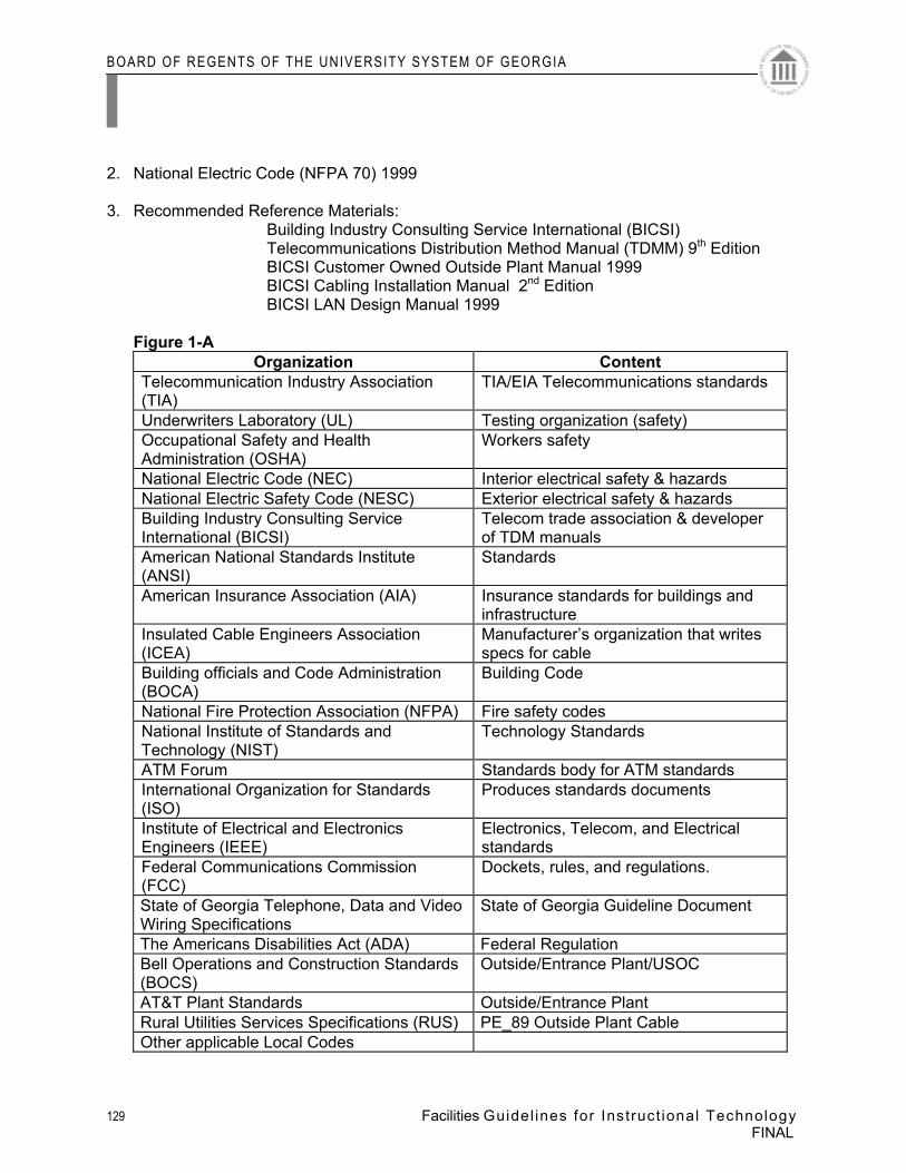
BOARD OF REGENTS OF THE UNIVERSITY SYSTEM OF GEORGIA
129 Facilities Guidel ines for Instruct ional Technology
FINAL
2. National Electric Code (NFPA 70) 1999 3. Recommended Reference Materials:
Building Industry Consulting Service International (BICSI) Telecommunications Distribution Method Manual (TDMM) 9th Edition
BICSI Customer Owned Outside Plant Manual 1999 BICSI Cabling Installation Manual 2nd Edition
BICSI LAN Design Manual 1999
Figure 1-A Organization Content
Telecommunication Industry Association (TIA)
TIA/EIA Telecommunications standards
Underwriters Laboratory (UL) Testing organization (safety) Occupational Safety and Health Administration (OSHA)
Workers safety
National Electric Code (NEC) Interior electrical safety & hazards National Electric Safety Code (NESC) Exterior electrical safety & hazards Building Industry Consulting Service International (BICSI)
Telecom trade association & developer of TDM manuals
American National Standards Institute (ANSI)
Standards
American Insurance Association (AIA) Insurance standards for buildings and infrastructure
Insulated Cable Engineers Association (ICEA)
Manufacturer’s organization that writes specs for cable
Building officials and Code Administration (BOCA)
Building Code
National Fire Protection Association (NFPA) Fire safety codes National Institute of Standards and Technology (NIST)
Technology Standards
ATM Forum Standards body for ATM standards International Organization for Standards (ISO)
Produces standards documents
Institute of Electrical and Electronics Engineers (IEEE)
Electronics, Telecom, and Electrical standards
Federal Communications Commission (FCC)
Dockets, rules, and regulations.
State of Georgia Telephone, Data and Video Wiring Specifications
State of Georgia Guideline Document
The Americans Disabilities Act (ADA) Federal Regulation Bell Operations and Construction Standards (BOCS)
Outside/Entrance Plant/USOC
AT&T Plant Standards Outside/Entrance Plant Rural Utilities Services Specifications (RUS) PE_89 Outside Plant Cable Other applicable Local Codes
BOARD OF REGENTS OF THE UNIVERSITY SYSTEM OF GEORGIA
130 Facilities Guidel ines for Instruct ional Technology
FINAL
Outside Information Sources For space needs analysis, the Space Planning Guidelines for Institutions of Higher Education is available by contacting the Council of Educational Facility Planners International (CEFPI) at 602.948.2337 (tel) or 602.948.4420 (fax). For two-year institutions, the Colorado Commission on Higher Education Policy Manual contains specific lab space standards, which are available by contacting Kirk Mlinek at the Colorado Commission on Higher Education (CCHE) at 303.894.2935 or at [email protected] Information on current codes and regulations for the State of Georgia are available by contacting the Georgia Department of Community Affairs at 404.656.3836 The State of Georgia currently maintains a GIS data clearinghouse in the Web. Topographic information for portions of the State of Georgia is available at http://www.GIS.State.Ga.US/ The Society for College and University Planning (SCUP) Planning Pages are located at http://www.umich.edu/~scup/ 2. Checklists CAMPUS INFRASTRUCTURE COMMUNICATIONS
BOARD OF REGENTS OF THE UNIVERSITY SYSTEM OF GEORGIA
131 Facilities Guidel ines for Instruct ional Technology
FINAL
A access point (AP) The central or control point in a wireless cell that acts as a bridge for traffic to and from wireless devices in the cell. The AP also connects wireless devices to the wired portion of the LAN. access provider (AP) A company, such as a telephone company, that provides a circuit path between a service provider and the client user. An access provider can also be the service provider. administration* The method for labeling, documentation, and usage needed to implement moves, additions, and changes of the telecommunications infrastructure. American wire gauge (AWG) A system used to specify wire size. The greater the wire diameter, the smaller value (e.g., 24 AWG [0.51 mm (0.020 in)]. American Society of Heating, Refrigerating, and Air- Conditioning Engineers (ASHRAE) An international society organized for the sole purpose of advancing the arts and sciences of heating, ventilating, air conditioning, and refrigerating for the public’s benefit through research, standards writing, continuing education, and publications. Americans with Disabilities Act( ADA) U. S. Department of Justice regulations and guidelines under civil rights law that ensure individuals with disabilities have access to, or may use, public entities and government buildings. ampere (A) Unit of electric current. One ampere is equal to the current produced by one volt acting through a resistance of one ohm. Amplifier An electronic device that takes an incoming signal and increases the signal strength so that the signal can transmit a greater distance. Analog A format that uses variable such as voltage amplitude or frequency variations to transmit information. Annunciator A signaling device, usually electrically operated, that gives an audible and/ or visual signal when energized. approved ground A ground that has been approved for use by the authority having jurisdiction. See earth ground and ground. Armoring Cable protection, usually made of corrugated steel, or PVC for protection against severe outdoor environments, rodents, or other physical damage. as- built drawing A final form of drawing in electronic or hard- copy format inclusive of all “record copy” information and notes. B badge reader A security system device that reads coded cards or badges. Synonym: card reader. Backboard A panel (e. g., wood or metal) used for mounting connecting hardware and equipment. backbone* A facility (e. g., pathway, cable, or conductors) between telecommunications rooms, or floor distribution terminals, the entrance facilities, and the equipment rooms within or between buildings. backbone cable* See backbone and backbone cabling. backbone cabling Cable and connecting hardware that provides interconnections between telecommunications rooms, equipment rooms, and entrance facilities. See backbone. backbone loop diversity A type of loop diversity that assigns circuits among different intrabuilding backbone cables. backbone network An intermediate data network connecting two or more LANs. backbone pathway The portion of the pathway system that permits the placing of backbone cables between the entrance location and all cross- connect points within a building and between buildings. backbone raceway See backbone pathway. Backup A copy of the data stored on a device.
APPENDIX
Glossary
BOARD OF REGENTS OF THE UNIVERSITY SYSTEM OF GEORGIA
132 Facilities Guidel ines for Instruct ional Technology
FINAL
Bandwidth A range of frequencies, usually the difference between the upper and lower limits of the range, expressed in Hz. It is used to denote the potential capacity of the medium, device, or system. In copper and optical fiber cabling, the bandwidth decreases with increasing length. bend radius Maximum radius that a cable can be bent to avoid physical or electrical damage or cause adverse transmission performance. bits per second (b/ s) A unit of measure used to express the data transfer rate. Commonly used rates include kilobit per second (kb/ s), megabit per second (Mb/ s), and gigabit per second (Gb/ s). Bonding The permanent joining of metallic parts to form an electrically conductive path that will assure electrical continuity, the capacity to safely conduct any current likely to be imposed, and the ability to limit differences in potentials between the joined parts. bonding conductor (BC) A conductor used specifically for the purpose of bonding. break- out cable Multifiber cables where each optical fiber is further protected by an additional jacket and optional strength elements. Bridge An internetworking device used to connect separate LANs or to link two network segments, and to filter information between them as well as traffic, collisions, and other network problems. The transport takes place at the media access control level (Layer 2 in the Open Systems Interconnection model). Broadband A general term for transmission of signals that have wide bandwidth (e. g., integrated services digital network) or multiple modulated channels (e. g., 10BROAD- 36). broadband transmission The transmission of multiple signals on a medium at the same time, sharing the entire bandwidth of the medium. The video signals are multiplexed into channels with a bandwidth of 6 MHz each and occupy a different frequency on the cable. The signals are divided, usually by frequency divisions, to allow more than one channel on the cable at any time. Browser Applications software used to access Web- based content. building core* A three- dimensional space, permeating one or more floors of the building and used for the extension and distribution of utility services (e. g., elevators, washrooms, stairwells, mechanical and electrical systems, and telecommunications) throughout the building. building entrance The room or space inside a building where telecommunications cables enter and leave the building. See entrance facility (telecommunications). building entrance terminal Cable termination equipment used to terminate outside plant cables at or near the point of building entry. building module The standard selected as the dimensional coordination for the design of the building. The module is usually a multiple of 100 mm (4 in), as the international standards have established a 100 mm (4 in) basic module. This produces modular coordination to all building materials, products, and utilization of the floor space. bundled cable* An assembly of two or more cabling continuously bound together to form a single unit. Not to be confused with hybrid cable. buried cable See direct- buried cable. Byte A data unit made up of eight bits, sometimes referred to as an octet. Megabytes and gigabytes are commonly used measures of storage or memory capacity. C Cabinet An enclosed container with four rails used for mounting a wide variety of miscellaneous equipment inside them (e. g., fans, power strips, connection devices, terminations, apparatus, cables, wires, equipment, etc.). They are available in a wide variety of sizes for either wall- mounting or self- supporting. cable (CA) An assembly of one or more insulated conductors or optical fibers within an enveloping sheath, constructed to permit use of the conductors or optical fibers singly or in groups. See aerial cable; direct- buried cable; hard- sheath cable; underground cable. cable labeling system 1. Scheme adapted for labeling cables to identify them based on ANSI/ TIA/ EIA- 606, Administration Standard for the Telecommunications Infrastructure of Commercial Buildings. 2. The scheme employed when identifying cable or its associated hardware. cable rack The vertical or horizontal open support structure (usually made of aluminum or steel) that is attached to a ceiling or wall.
BOARD OF REGENTS OF THE UNIVERSITY SYSTEM OF GEORGIA
133 Facilities Guidel ines for Instruct ional Technology
FINAL
cable sheath* A covering over the optical fiber or conductor assembly that may include one or more metallic members, strength members, or jackets. cable terminal An assembly used to access the conductors of a cable. cable tray (CT) A support mechanism used to route and support telecommunications cable or power cable. Typically equipped with sides that allow cables to be placed within the sides over its entire length. Cabling A combination of all copper and optical fiber telecommunications cables, equipment/ patch cords, and connecting hardware. Calibration Task of verifying test equipment against a reference to ensure proper operation. Campus The buildings and grounds of a complex, such as a college, university, industrial park, or military base having legal contiguous interconnection. campus distributor (CD) The distributor from which the campus backbone cabling emanates. card reader See badge reader. central office (CO) A place where an access provider terminates customer lines and the switching equipment that interconnects lines. central processing unit (CPU) That part of a computer in which logical operations are performed. centralized cabling An optical fiber cabling configuration, based on TIA/ EIA TSB72, Optical Fiber Cabling Guidelines, from the work area to a centralized cross- connect using pull- through cables, an interconnect, or splice in the telecommunications room. Cladding The transparent outer concentric glass layer that surrounds the optical fiber core and has a lower index of refraction than the core. It provides total internal reflection and protects against scattering from contaminants at the core surface. Client A network device that requests services from a server. client/ server model A form of distributed computing in which a series of interdependent tasks are processed by two or more computers on a network, allowing client devices with limited processing capabilities to gain access to the available resources of one or more servers attached to the network. client software Additions to a station’s operating system that enable access to network resources. closed circuit television (CCTV) A private television system typically used for security purposes. Coating A material put on an optical fiber during the drawing process to protect it from the environment. See buffer coating. Coax See coaxial cable. coaxial cable An unbalanced cable consisting of a central metallic core surrounded by a layer of insulating material. This insulating (dielectric) material may be a solid material or air spaced. The entire assembly is covered with a metallic mesh or solid metallic sleeve and protected by an outer layer of non- conducting material (cable jacket). collapsed backbone 1. A backbone network connecting all network segments within a hub bus, allowing for the possibility of speeds far exceeding the standard capability of a standard backbone media. 2. Using an enterprise hub as the hub backbone star concentrator, local hubs serve network segments over their bus and pass traffic over high-speed backbone fiber through the enterprise hub’s bus to other local hub’s collapsed backbone bus. This form of collapsed backbone is used in multifloor buildings or campus networks. common- mode voltage Asymmetrical noise voltage that appears equally and in phase from each conductor, relative to ground potential. Contrast with differential- mode voltage. communications plenum cable (CMP) Cable listed as suitable for use in ducts, plenums, and other spaces used for environmental air. It has adequate fire- resistant and low smoke- producing characteristics. Cables must pass required test for fire and smoke characteristics of wires and cables, NFPA 262 or UL 910. communications protocol See protocol. communications riser cable (CMR) Cable listed as suitable for use in a vertical run in a shaft or from floor to floor. It has fire- resistant characteristics capable of preventing the carrying of fire from floor to floor. Cables must pass requirements of the Standard Test for Flame Propagation Height of Electrical and Optical- Fiber Cable Installed Vertically in Shafts, ANSI/ UL 1666. Conduit A rigid or flexible metallic or non- metallic raceway of circular cross- section through which cables can be pulled.
BOARD OF REGENTS OF THE UNIVERSITY SYSTEM OF GEORGIA
134 Facilities Guidel ines for Instruct ional Technology
FINAL
conduit run Multiple sections of conduit. connecting hardware A device, or combination of devices, used to connect two cables or cable elements. Connector A mechanical device used to provide a means for aligning, attaching, and achieving continuity between conductors or optical fibers. cross- connect* A facility enabling the termination of cable elements and their interconnection or cross- connection. cross- connection* A connection scheme between cabling runs, subsystems, and equipment using patch cords or jumpers that attach to connecting hardware on each end. Crosstalk The unwanted reception of electromagnetic signals on a communications circuit from another circuit. Current Flow of electrons in a conductor measured in amperes. customer premises equipment (CPE) Equipment residing on customer sites (e. g., PBX systems, key systems, data sets, etc.). D digital signal (DS) A signal with a fixed number of discrete values. Commonly, a binary signal with two values that are used to transmit the two states (0,1) used by digital computers. Most data transmission in optical fibers is by digital optical pulses. Contrast with analog signal. digital versatile disc (DVD) A compact disc (CD) that contains full- motion video. direct- buried cable* A telecommunications cable designed to be installed under the surface of the earth, in direct contact with the soil. direct current (dc) loop resistance Cable conductor resistance with the far end of the cabling shorted. This is the resistance for both conductors of a coaxial cable. direct digital control (DDC) A control loop used in building automation systems in which a microprocessor- based controller controls equipment (e. g., air handlers, chillers, boilers, etc.) based on sensor inputs and set- point parameters according to a sequence of operations. direct sound Sound that travels directly from a speaker to a listener. Dispersion 1. In most materials, the optical propagation parameters depend on wavelength. This causes the optical pulses to be broadened and have longer time duration. The three types of dispersion in optical fibers are modal, material, and waveguide. 2. The broadening of the input light pulses along the length of the fiber. distribution cable That part of the loop that connects the customer location to the customer feeder cable. See horizontal cabling. Downlink 1. Signals transmitted from satellites to ground stations. 2. In demand priority access method, the communications channel between a repeater and a connected end node or between a repeater and a lower- level repeater. Duct 1. A single enclosed pathway for conductors or cables, usually placed in soil or concrete. 2. An enclosure in which air is moved. Generally part of the heating, ventilating, and air conditioning system of a building. ductbank (DB)* An arrangement of ducts, for wires or cables, in tiers. E earth ground An electrical connection to earth obtained by a grounding electrode system. See ground (gnd). Easement A right acquired by one party to use lands belonging to another party for a specific purpose. Elastomeric Made of one of several substances that resemble rubber (i. e., flexible). elastomeric firestop A flexible firestopping material resembling rubber. electromagnetic compatibility (EMC) The ability of a device, equipment, or system to function satisfactorily in its electromagnetic environment without introducing intolerable electromagnetic disturbances to anything in that environment or being affected by the environment in an undesirable way.
BOARD OF REGENTS OF THE UNIVERSITY SYSTEM OF GEORGIA
135 Facilities Guidel ines for Instruct ional Technology
FINAL
electromagnetic disturbance Any electromagnetic occurrence that may degrade the performance of a device, unit of equipment, or system. An electromagnetic disturbance may be noise, an unwanted signal, or a change in the propagation medium itself. electromagnetic emission The phenomenon by which electromagnetic energy emanates from a source. Emissions can be either radiated or conducted. electromagnetic immunity The ability of a device, equipment, or system to perform without degradation in the presence of an electromagnetic disturbance. electromagnetic interference (EMI) Any electrical or electromagnetic interference that causes undesirable signals on a device, equipment, or system. Electronic Industries Alliance (EIA) The alliance is organized along specific electronic product and market lines, and, as a standards association, develops and publishes industry guidelines. electrostatic discharge (ESD) Electrical discharges of static electricity generated by interaction of dissimilar materials. emergency power A stand- alone secondary electrical supply source that is activated when service from the primary electrical source is interrupted. Equalizer An electronic device with a frequency response that is the opposite of the cable that feeds into it. equipment closet (EC) See telecommunications room. equipment room (ER) (telecommunications) A centralized space for telecommunications equipment that serves the occupants of a building. Equipment housed therein is considered distinct from a telecommunications room because of its nature or complexity. F Federal Communications Commission (FCC) Regulatory body for U. S. interstate telecommunications services and international service originating in the United States. Feedback An unwanted oscillation or tone that quickly grows in loudness. Fiber Thin filament of glass or plastic that conducts a light signal. See optical fiber and plastic optical fiber (POF). fiber optics Optical technology concerned with the transmission of radiant light through fibers made of transparent materials such as glass, fused (vitreous) silica, or plastic. Fireproof A property of a material such as masonry, block, brick, concrete, and gypsum board that does not support combustion even under accelerated conditions. No material is entirely fireproof. fire- rated door A door assembled of various materials and types of construction used in wall openings to retard the passage of fire. These doors are rated in hours or fractions of hours. fire rating system See fire resistance rating. fire resistance rating* The time in hours, or fraction of an hour, that a material or assembly of materials will withstand the passage of flame and the transmission of heat when exposed to fire under specified conditions of test and performance criteria. fire shield A material, device, or assembly of parts used to prevent propagation of flames from one cable system or pathway to an adjacent cable system or pathway (e. g., between two parallel cable trays or between layers in vertically stacked trays). Firestop A material, device, or assembly of parts in an architectural barrier to prevent vertical or horizontal passage of flame, smoke, water, or gases through the rated barrier. firestop/ firestop seal/ penetration seal Special combination of materials that are installed in fire- rated barrier openings around the penetrating elements and create a seal against the spread of fire, smoke, and extreme temperatures through the penetrations. Firestopping The process of installing specialty materials into penetrations of fire- rated barriers to re- establish the integrity of the barrier. See cementitious firestop and elastomeric firestop. firestop system A specific construction consisting of the material( s) (firestop penetration seals) that fill the opening in the wall or floor assembly, and around and between any items that penetrate the wall or floor (e. g., cables, cable trays, conduit, ducts, pipes), and any termination devices (e. g., electrical outlet boxes), along with their means of support. Firewall 1. A wall that helps prevent fire spreading from one fire zone or area to another, and that runs from structural floor to structural ceiling. 2. One or more security mechanisms designed for access control
BOARD OF REGENTS OF THE UNIVERSITY SYSTEM OF GEORGIA
136 Facilities Guidel ines for Instruct ional Technology
FINAL
and authentication to prevent, detect, suppress, and/ or contain unauthorized access to a network. Firewalls are designed to keep unwanted and unauthorized traffic from a protected network. furniture system Furniture walls combined with furniture units designed to form a work area (e. g., a cubicle). furniture wall A component of a furniture system. Fuse An overcurrent protective device with a circuit- opening fusible element that is severed (open) when heated by the passage of an overcurrent. Fuses are normally one- time devices; once they are open, they are not reusable. G Gateway The interconnection between two networks with different communications protocols. Gateways normally operate at one or more of the top four layers of the Open Systems Interconnection Reference Model. Gigabit Ethernet A carrier sense multiple access with collision detection LAN standard developed by the IEEE 802 group operating at one Gb/ s. Grommet A protective edging placed around a hole. ground (gnd) A conducting connection, whether intentional or accidental, between an electrical circuit (e. g., telecommunications) or equipment and the earth, or to some conducting body that serves in place of earth. ground electrode A conductor, usually a rod, pipe, or plate (or group of such conductors), in direct contact with the earth providing a connection point to the earth. ground loop Considered to be an additional ground path that may cause interference in communications links. If properly bonded, ground loops do not have to be a source of trouble. ground wire See grounding conductor. grounding conductor A conductor used to connect electrical equipment to the grounding electrode to the building’s main grounding busbar. H hertz (Hz) A unit of frequency equal to one cycle per second. high- rise building A multistory building (at least three stories) of structural steel or reinforced concrete construction. home run A pathway or cable between two locations without a splice or intermediate termination points in between. horizontal cabling The cabling between and including the work area telecommunications outlet/ connector and the horizontal cross- connect (floor distributor) in the telecommunications room. horizontal cross-connect( HC) A group of connectors, such as patch panel or punch- down block, that allows equipment and backbone cabling to be cross- connected with patch cords or jumpers. Floor distributor is the international term for horizontal cross-connect. horizontal HC- CP cable The segment of horizontal cable permanently installed between the horizontal cross- connect (HC) and the consolidation point (CP) connector. Hub A network device that provides a centralized point for LAN communications, media connections, and management activities of a physical star topology cabling system. It is used to control and direct the flow of data through a structured cabling network. I Impedance A unit of measure expressed in ohms. The total opposition (resistance, capacitance, and inductance) a circuit, cable, or component offers to the flow of alternating current. Infrastructure Permanently installed cable plant. infrastructure (telecommunications)* 1. A collection of those telecommunications components, excluding equipment, that together provide the basic support for the distribution of all information within a building or campus. 2. Substructure of system used to support the cable plant being installed. Innerduct A non- metallic pathway placed within a larger pathway. input impedance The ratio of the voltage at the sending end of the line to the current in the line at the sending end.
BOARD OF REGENTS OF THE UNIVERSITY SYSTEM OF GEORGIA
137 Facilities Guidel ines for Instruct ional Technology
FINAL
integrated services digital network (ISDN) A fully digital communications facility designed to provide transparent end- to- end transmission of voice, data, video, and still images across the public switched telephone network. Access to the service is at one of two rates: the basic rate of 144 kb/ s is provided as two B data channels of 64 kb/ s and one D control channel of 16 kb/ s. The second primary rate is 2.048 Mb/ s in Europe and 1.544 Mb/ s in the United States, Japan, and Canada and is often referred to as 30B+ D. interbuilding (campus) backbone A backbone network providing communications between more than one building. Interconnection A connection scheme that provides for the connection of a cable to another cable or to an equipment cable. intermediate cross-connect (IC) The connection point between a backbone cable that extends from the main cross-connect (campus distributor [first- level backbone]) and the backbone cable from the horizontal cross-connect (floor distributor [second- level backbone]). Building distributor is the international term for intermediate cross-connect. intermediate network A network used to connect two or more networks. Internet A worldwide network of computers (servers) that links the user to businesses, government agencies, universities, and individuals. Internet protocol (IP) A Network layer routing protocol used by all devices connected to the Internet. IP is a simple connectionless service that provides no retransmission capabilities. intrabuilding backbone A backbone network providing communications within a building. Intranet A collection of Internet- based technologies designed to provide content to users on an internal network. The content is viewed using a Web browser. J Jack See modular jack. K kilowatt (kW) A unit of electrical power equal to 1000 watts. kilowatt hour (kWh) Watts indicate the amount of power that is consumed by a circuit during a given period of time. Utility companies charge for power in kWh. L ladder rack A device similar to a cable tray but more closely resembles a single section of a ladder. It is constructed of metal with two sides affixed to horizontal cross members. ladder tray See cable tray (CT). LAN address See medium access control (MAC) address. light- emitting diode (LED) A semiconductor diode that spontaneously emits incoherent light from the p- n junction when forward current is applied. It converts information from electrical to optical form. An LED typically has a large spectral width. LEDs give moderate performance at lower prices than laser diodes. LEDs are commonly used with multimode fiber in data enterprise and industrial applications. lightning down conductor A metallic conductor running vertically down a building, connecting the air terminals, and equalizing conductors to the lightning ground terminals. lightning equalizing conductor A closed metallic loop around the top and bottom of a building that aids in equalizing the potential of a lightning strike over the entire building and offers multiple connection points to the ground terminals. lightning ground terminal A grounded metallic conductor installed for lightning protection. lightning rod See air terminal. Local A geographic zone large enough to encompass a multibuilding campus. See metropolitan. local area network (LAN) A geographically limited data communications system for a specific user group consisting of a group of interconnected computers sharing applications, data, and peripheral devices such as printers and CD- ROM drives intended for the local transport of data, video, and voice. local exchange carrier (LEC)* The telecommunications company that provides public switched network access service.
BOARD OF REGENTS OF THE UNIVERSITY SYSTEM OF GEORGIA
138 Facilities Guidel ines for Instruct ional Technology
FINAL
Loop 1. In telephone systems, the wire pair that connects the customer to the switching center. This path is called a loop because it is generally two wires electrically tied together through the customer terminal set when the customer goes off hook. 2. The OSP facilities that extend from a serving main entrance facility or remote site to the exchange boundary. 3. A communications channel from a switching center or an individual message distribution point to the user terminal. loop diversity The placing of alternate facilities to back up the main system in case of failure. See alternate route. M main cross-connect (MC) The cross-connect normally located in the (main) equipment room for cross- connection and interconnection of entrance cables, first- level backbone cables, and equipment cables. Campus distributor is the international term for main cross-connect. main terminal room See main terminal space. main terminal space * The location of the cross- connect point of incoming cables from the telecommunications external network and the premises cable system. maintenance hole (MH) *1. In telecommunications, a vault located in the ground or earth as part of an underground duct system and used to facilitate placing, connectorization, and maintenance of cables as well as the placing of associated equipment, in which it is expected that a person will enter to perform work. Formerly called manhole. 2. A hole through which a person may go to gain access to an underground or enclosed structure. 3. Space used to access and maintain underground cable plant. Manhole See maintenance hole. megabit per second (Mb/ s) A unit of measure used to express the data transfer rate of a system, device, or communications channel. megahertz (MHz) A unit of frequency equal to one million cycles per second (hertz). modular jack* A female telecommunications connector that may be keyed or unkeyed and may have six or eight contact positions, but not all the positions need be equipped with jack contacts. multimode fiber An optical waveguide that allows many bound modes to propagate. multiple access In satellite communications, the capability of a communications satellite having simultaneous access to one communications satellite from a number of ground stations. multiplex (mux) Combining two or more signals into a single wave (the multiplex wave) from which the signals can be individually recovered. See multiplexing. multiplexer (mux) A device that combines two or more signals over a single communications channel (e. g., time- division multiplexing and wavelength- division multiplexing). multiplexing (muxing) The combining of two or more communications channels into a common, high- capacity channel from which the original signals may be individually recovered. N National Fire Protection Association (NFPA ® ) Association that writes and administers the National Electrical Code ® (NEC ® ). network address An address used to uniquely identify each LAN connected to an internetwork. See application address and medium access control (MAC) address. O open office An area of floor space with division provided by furniture, movable partitions, or other temporary means instead of by building walls. open office cabling The cabling that distributes from the telecommunications room to the open office area utilizing a consolidation point or multi- user telecommunications outlet. operating system (OS) Software that controls the execution of all programs and the utilization of resources on a device such as a PC. optical fiber Transmission medium using glass or plastic to transmit pulse light signals. Its bandwidth is higher than copper and not subject to electromagnetic interference. The optical fiber consists of a central core (glass or plastic) and an outer cladding. See fiber and plastic optical fiber. optical fiber cable Cable made up of one or more strands of optical fibers, strength members, and an outer jacket.
BOARD OF REGENTS OF THE UNIVERSITY SYSTEM OF GEORGIA
139 Facilities Guidel ines for Instruct ional Technology
FINAL
optical fiber cladding The outer layer of glass surrounding the light- carrying core of the optical fiber. It has a lower refractive index than the core, which serves to confine the light to the core. optical fiber core The central part of an optical fiber that is used to carry the light pulses, made of glass or plastic. P Packet A group of bits, including data and control elements that are switched and transmitted together. packet switching A data communications switching and transmission system in which an input data stream is broken down into uniform data packets. Each packet is transmitted independently between devices through the network without first establishing a dedicated communications path between the devices. At the receiving end, the packets are checked for errors, resequenced as necessary, and combined into an output data stream. patch cord A length of cable with connectors on one or both ends used to join telecommunications circuits/ links at the cross- connect. Penetration Opening made in fire- rated barrier (architectural structure or assembly). There are two kinds of penetrations: • Membrane penetration pierces or interrupts the outside surface of only one side of a fire- rated barrier. • Through penetration completely transmits a fire- rated barrier, piercing both outside surfaces of the barrier. peripheral device Equipment typically externally connected to and controlled by a PC or directly by a plenum* A compartment or chamber to which one or more air ducts are connected and that forms part of the air distribution system. Because it is part of the air distribution system, cables installed in this space require a higher fire rating. power pole Correctly termed a utility column. It is a vertical pathway used to house cables that run from above a suspended ceiling to the termination location in a work area. private branch exchange (PBX) A device allowing private local voice (and other voice- related services) switching over a network. Protocol A set of rules and procedures governing the formatting of messages and the timing of their exchange between devices on a network covering addressing, transmitting, receiving, and verifying. pull box (PB) A device to access a raceway used to facilitate placing of wire or cables. pull cord Cord placed within a cable pathway, used to pull wire and cable. See drag line. pull wire See pull cord. Q R Raceway Any enclosed channel designed for holding wires, cables, or busbars. Rack See cable rack. radio frequency interference (RFI) A disturbance in the reception of radio and other electromagnetic signals due to conflict with undesired signals having components in the radio frequency range. record copy drawing Set of drawings that are “hand marked” during the construction phase of a project to document changes that have been made that are used as the source for updates to the design drawings to create as- built drawings. Repeater An internetworking device that consists of a transmitter and a receiver and is used to amplify (analog) and regenerate (digital) a signal to increase the length of a segment. A multiport repeater will extend the overall reach of the LAN. request for quotation (RFQ) A document that solicits quotes for telecommunications projects or equipment and provides vendors with all the information necessary to prepare a quote. riser cable See backbone. riser closet See telecommunications room. Router An internetworking device operating at the Network layer of the Open Systems Interconnection model, to direct packets from one network to another. S Scalability The ability of a network to grow without degradation of quality.
BOARD OF REGENTS OF THE UNIVERSITY SYSTEM OF GEORGIA
140 Facilities Guidel ines for Instruct ional Technology
FINAL
Security Protection against unauthorized activities, generally requiring a combination of access controls, data integrity, and transaction confidentiality. security and access control (SAC) Equipment associated with systems used to monitor and control devices such as card readers, door alarms, and closed circuit television (CCTV). Server A network device that combines hardware and software to provide and manage shared services and resources on the network. service clearance The space encompassing the equipment, or unit, that is required to permit proper working room for operating, inspecting, and servicing equipment. service entrance* See entrance facility. service loop A field- configured coil of cable arranged at the point of termination to facilitate future arrangements. service provider (SP) A company that provides connection to a part of the Internet, or other services such as application programming interfaces. An SP, when reached by the user through an access provider (AP), becomes the AP to the service they provide. See access provider (AP). shared tenant service (STS) Consolidates former individual- line subscribers using a common premises switch. Shield Metallic layer placed around a conductor or group of conductors to prevent electrostatic or electromagnetic coupling between the enclosed wires and external fields. shielded twisted- pair (STP) cable Cable made up of multiple twisted copper pairs, each pair with an individual shield. The entire structure is then covered with an overall shield or braid and an insulating sheath (cable jacket). Standard A collection of requirements that encompasses properties of components and systems that are intended to ensure an accepted degree of functionality and longevity. Standards are intended to reflect accepted norms as typically determined through a balloting process conducted by a nationally or internationally accredited organization. step- index fiber An optical fiber, either multimode or singlemode, in which the core refractive index is uniform throughout so that a sharp step in refractive index occurs at the core- to- cladding interface. Strand 1. A single string of wire used to make up a larger wire or cable by twisting a number of strands together. Galvanized steel stranded cable is used as support strand and guy wire. Support strand is listed by strength (e. g., a 6M strand is rated at 2.72 kg [6000 lb] of strength). 2. A single unit of optical fiber within a cable (e. g., a 12- strand fiber cable has 12 individual optical fibers within the cable sheath). 3. Steel cables composed of several wires twisted together. Subduct See innerduct. Submittal Information that a contractor must submit to the design team for review and approval. support strand A strong element (e. g., steel strand) used to carry the weight of the telecommunications cable and wiring. surety bond A bond that ensures a respondent (bidder) to a request for quote (RFQ) is sincerely interested in performing the project and has responded accurately to the RFQ specifications. suspended ceiling A ceiling that creates an area or space between the ceiling material and the building structure above the material. This area may or may not be an air handling space requiring plenum rules of a national code. The design of the air conditioning/ heating system determines this. Switch 1. A multiport bridge and repeater on which each port represents a separate network communications channel. 2. A voice communications device that utilizes switching technology to establish and terminate calls (e. g., PBX). Switching Establishing a direct signal path from one device to another on an as- needed basis. T Telecommunications A branch of technology concerned with the transmission, emission, and reception of signs, signals, writing, images, and sounds; that is, information of any nature by cable, radio, optical, or other electromagnetic systems. telecommunications bonding backbone (TBB) A conductor that interconnects the telecommunications main grounding busbar (TMGB) to the telecommunications grounding busbar (TGB).
BOARD OF REGENTS OF THE UNIVERSITY SYSTEM OF GEORGIA
141 Facilities Guidel ines for Instruct ional Technology
FINAL
telecommunications bonding backbone interconnecting bonding conductor (TBBIBC) A conductor utilized to interconnect two or more telecommunications bonding backbones. telecommunications closet (TC) See telecommunications room.. telecommunications grounding busbar (TGB)* A common point of connection for telecommunications system and equipment bonding to ground; located in the telecommunications room or equipment room. Telecommunications Industry Association (TIA) A standards association that publishes telecommunications standards and other documents. telecommunications main grounding busbar (TMGB)* A busbar placed in a convenient and accessible location and bonded, by means of the bonding conductor for telecommunications, to the building service equipment (power) ground. telecommunications outlet (TO)* See outlet/ connector (telecommunications). telecommunications room (TR) An enclosed space for housing telecommunications equipment, cable terminations, and cross-connects. The room is the recognized cross-connect between the backbone cable and horizontal cabling. telecommunications service entrance* See entrance facility (telecommunications). terminal (TERM) 1. A point at which information may enter or leave a telecommunications network. 2. The input- output associated equipment. 3. A device that connects wires to each other. terminal emulation Software application that allows PC stations to emulate mainframe or other non- PC applications. See emulation. Termination 1. The ending of a transmission or transmission pathway. 2. The act of connecting a cable/ wire/ fiber to connecting hardware. termination hardware* This term is outmoded. See connecting hardware. time domain reflectometer (TDR) A device that sends a signal down a cable, then measures the magnitude and amount of time required for the reflection of that signal to return. TDRs are used to measure the length of cables as well as locate cable faults. Tray See cable tray. Trench A furrow dug into the earth for the placement of direct- buried cable, or for the installation of conduit ducts. trench duct An interior or exterior trough embedded in concrete that has removable cover plates level with the top of the surrounding surface. See header duct. trough (cable) A pathway system and fittings formed and constructed so that insulated conductors and cables may be readily installed or removed without injury either to conductors or their coverings after the cable trough has been completely installed. See cable tray. trunk cable The term trunk refers to the main distribution cable. A typical trunk begins at the headend and terminates at the outermost feeder cable. twisted- pair Two individually insulated copper wires physically twisted together to form a balanced pair. twisted- pair cable A multiconductor cable comprising two or more copper conductors twisted in a manner designed to cancel electrical interference. Formerly unshielded twisted- pair (UTP). U underfloor raceway* A pathway placed within the floor and from which wires and cables emerge to a specific floor area. underground cable *A telecommunications cable designed to be installed under the surface of the earth in a trough or duct that isolates the cable from direct contact with the soil. See direct- buried cable. unigrounded power system vA power system where only one point, usually the midpoint, of the supply transformer bank is grounded. The neutral conductor may or may not be carried along with the phase wires. Uplink 1. Signals transmitted from ground stations to satellites. 2. In demand priority access method, the communications channel between a connected end node and a repeater, or between a repeater and a higher- level repeater. utility column* An enclosed pathway extending from the ceiling to furniture or to the floor that forms a pathway for electrical wiring, telecommunications cable, or both. utility pole See utility column..
BOARD OF REGENTS OF THE UNIVERSITY SYSTEM OF GEORGIA
142 Facilities Guidel ines for Instruct ional Technology
FINAL
variable air volume (VAV) A self- contained heating, ventilating, and air- conditioning (HVAC) unit that uses a built- in microprocessor- based controller to control environmental air to a specific zone via a damper. The unit is placed near the end of a HVAC duct and can also monitor temperature inputs from local sensors. Vault A telecommunications space, typically subterranean, located within or between buildings and used for the distribution, splicing, and termination of cabling. These spaces may be established as a maintenance hole in campus environments or they may include active equipment in addition to passive cabling such as in a controlled environment vault (CEV). virtual circuit A temporary communications link through an internetwork that appears to be a dedicated circuit between two network devices. virtual LAN (VLAN) A technique, made possible by switching technologies, that permits the logical grouping of any number of network devices into one or more subnetworks, to improve traffic management and/ or security. wavelength The length of a wave measured from any point on one wave to the corresponding point on the next wave, such as from crest to crest. The wavelength of light is usually measured in nanometers (nm). Web Used as a noun, it is shorthand for the World Wide Web (www) services found on the Internet. wire* An individually insulated solid or stranded metallic conductor. wireway (WW) A supported pathway for cables. Wiring See cabling. wiring closet See telecommunications room. work area (WA) * A building space where the occupants interact with telecommunications terminal equipment. work area outlet A device placed at user workstation for termination of horizontal media and for connectivity of network equipment. workstation A telecommunications device used in communicating with another telecommunications device. References: 1)TDM Manual on CD- ROM, 9 th edition © 2000 BICSI ® 2)* Terms marked with an asterisk are reprinted with permission of Telecommunications Industry Association (TIA). Complete copies of all TIA standards can be purchased through Global Engineering Documents at 800- 854- 7179 or 303- 397- 7956. 3)† Terms marked with a dagger are reprinted with permission of CISCO Systems, Inc