Embed Size (px)
Citation preview

November 2003
NASA/TM-2003-212663
Failure Criteria for FRP Laminates in Plane Stress Carlos G. Dávila Langley Research Center, Hampton, Virginia Pedro P. Camanho University of Porto, Porto, Portugal
https://ntrs.nasa.gov/search.jsp?R=20040001363 2020-04-14T03:37:28+00:00Z

The NASA STI Program Office . . . in Profile
Since its founding, NASA has been dedicated to the advancement of aeronautics and space science. The NASA Scientific and Technical Information (STI) Program Office plays a key part in helping NASA maintain this important role.
The NASA STI Program Office is operated by Langley Research Center, the lead center for NASA’s scientific and technical information. The NASA STI Program Office provides access to the NASA STI Database, the largest collection of aeronautical and space science STI in the world. The Program Office is also NASA’s institutional mechanism for disseminating the results of its research and development activities. These results are published by NASA in the NASA STI Report Series, which includes the following report types:
• TECHNICAL PUBLICATION. Reports of
completed research or a major significant phase of research that present the results of NASA programs and include extensive data or theoretical analysis. Includes compilations of significant scientific and technical data and information deemed to be of continuing reference value. NASA counterpart of peer-reviewed formal professional papers, but having less stringent limitations on manuscript length and extent of graphic presentations.
• TECHNICAL MEMORANDUM. Scientific
and technical findings that are preliminary or of specialized interest, e.g., quick release reports, working papers, and bibliographies that contain minimal annotation. Does not contain extensive analysis.
• CONTRACTOR REPORT. Scientific and
technical findings by NASA-sponsored contractors and grantees.
• CONFERENCE PUBLICATION. Collected
papers from scientific and technical conferences, symposia, seminars, or other meetings sponsored or co-sponsored by NASA.
• SPECIAL PUBLICATION. Scientific,
technical, or historical information from NASA programs, projects, and missions, often concerned with subjects having substantial public interest.
• TECHNICAL TRANSLATION. English-
language translations of foreign scientific and technical material pertinent to NASA’s mission.
Specialized services that complement the STI Program Office’s diverse offerings include creating custom thesauri, building customized databases, organizing and publishing research results ... even providing videos. For more information about the NASA STI Program Office, see the following: • Access the NASA STI Program Home Page at
http://www.sti.nasa.gov • E-mail your question via the Internet to
[email protected] • Fax your question to the NASA STI Help Desk
at (301) 621-0134 • Phone the NASA STI Help Desk at
(301) 621-0390 • Write to:
NASA STI Help Desk NASA Center for AeroSpace Information 7121 Standard Drive Hanover, MD 21076-1320

National Aeronautics and Space Administration Langley Research Center Hampton, Virginia 23681-2199
November 2003
NASA/TM-2003-212663
Failure Criteria for FRP Laminates in Plane Stress Carlos G. Dávila Langley Research Center, Hampton, Virginia Pedro P. Camanho University of Porto, Porto, Portugal

Available from: NASA Center for AeroSpace Information (CASI) National Technical Information Service (NTIS) 7121 Standard Drive 5285 Port Royal Road Hanover, MD 21076-1320 Springfield, VA 22161-2171 (301) 621-0390 (703) 605-6000

FAILURE CRITERIA FOR FRP LAMINATES IN PLANE STRESS
Carlos G. Dávila and Pedro P. Camanho
Abstract A new set of six failure criteria for fiber reinforced polymer laminates is
described. Derived from Dvorak’s fracture mechanics analyses of cracked plies and from Puck’s action plane concept, the physically-based criteria, denoted LaRC03, predict matrix and fiber failure accurately without requiring curve-fitting parameters. For matrix failure under transverse compression, the fracture plane is calculated by maximizing the Mohr-Coulomb effective stresses. A criterion for fiber kinking is obtained by calculating the fiber misalignment under load, and applying the matrix failure criterion in the coordinate frame of the misalignment. Fracture mechanics models of matrix cracks are used to develop a criterion for matrix in tension and to calculate the associated in-situ strengths. The LaRC03 criteria are applied to a few examples to predict failure load envelopes and to predict the failure mode for each region of the envelope. The analysis results are compared to the predictions using other available failure criteria and with experimental results. Predictions obtained with LaRC03 correlate well with the experimental results.
Introduction The aim of damage mechanics, the mathematical science dealing with quantitative descriptions of the
physical events that alter a material when it is subjected to loads, is to develop a framework that de-scribes the material response caused by the evolving damage state. The greatest difficulty in the develop-ment of an accurate and computationally efficient numerical procedure to predict damage growth has to do with how to analyze the material micro-structural changes and how to relate those changes to the material response. Several theories have been proposed for predicting failure of composites. Although significant progress has been made in this area, there is currently no single theory that accurately predicts failure at all levels of analysis, for all loading conditions, and for all types of fiber reinforced polymer (FRP) laminates. While some failure theories have a physical basis, most theories represent attempts to provide mathematical expressions that give a best fit of the available experimental data in a form that is practical from a designer’s point of view.
To the structural engineer, failure criteria must be applicable at the level of the lamina, the laminate, and the structural component. Failure at these levels is often the consequence of an accumulation of micro-level failure events. Therefore, an understanding of micro-level failure mechanisms is necessary in order to develop accurate failure theories.

2
The recent World Wide Failure Exercise1-7 (WWFE) conceived and conducted by Hinton and Soden provides a good assessment of the status of currently available theoretical methods for predicting material failure in fiber reinforced polymer composites. The recently published comparison of the predictions by the WWFE participants with experimental results indicates that even when analyzing simple laminates that have been studied extensively over the past 40 years, the predictions of most theories differ significantly from the experimental observations3.
The uncertainty in the prediction of initiation and progression of damage in composites has led to the undertaking of an effort at the NASA Langley Research Center to revisit existing failure theories, assess their capabilities, and to develop new theories where necessary. The present paper describes a newly developed set of six nonempirical criteria for predicting failure of unidirectional FRP laminates. All of the calculations presented are at the lamina level with plane stress assumptions. First, the motivation for non-empirical failure criteria for matrix shear and transverse tension and compression is established by examining several existing criteria. Next, new matrix failure criteria for matrix tension and compression are proposed. Then, a new fiber kinking failure criterion for fiber compression is developed by applying the matrix failure criteria to the configuration of the kink. The resulting set of six failure criteria is denoted LaRC03 and are summarized in the Appendix. Finally, some examples of failure envelopes are presented. The predicted results are compared to the results of other available failure criteria and with experimental results.
Strength-Based Failure Criteria Strength-based failure criteria are commonly used with the finite element method to predict failure
events in composite structures. A large number of continuum-based criteria have been derived to relate internal stresses and experimental measures of material strength to the onset of failure. One detailed discussion on the failure criteria proposed by Hashin, Puck, Sun and several others has been presented by París.8 París also discusses the ad hoc nature of the formulation of most strength-based criteria. In the following sections, the Hashin criteria9, 10 are briefly reviewed, and improvements proposed by Sun11 and Puck5, 6 over Hashin’s theories are examined.
Hashin Criteria 2D (1980)
Hashin established the need for failure criteria that are based on failure mechanisms. In his 1973 proposal, he used his experimental observations of failure of tensile specimens to propose two different failure criteria, one related to fiber failure and the other related to matrix failure. The criteria assume a quadratic interaction between the tractions acting on the plane of failure. In 1980, he introduced fiber and matrix failure criteria that distinguish between tension and compression failure. Given the difficulty in obtaining the plane of fracture for the matrix compression mode, Hashin used a quadratic interaction between stress invariants. Such derivation was based on logical reasoning rather than micromechanics. Although the Hashin criteria were developed for unidirectional laminates, they have also been applied successfully to progressive failure analyses of laminates by using in-situ unidirectional strengths12 to account for the constraining interactions between the plies. The two-dimensional versions of the failure criteria proposed by Hashin in 1973 and 1980 are summarized in Table 1.
Numerous studies conducted over the past decade indicate that the stress interactions proposed by Hashin do not always fit the experimental results, especially in the case of matrix or fiber compression. It is well known, for instance, that moderate transverse compression (σ22<0) increase the apparent shear strength of a ply, which is not well predicted by Hashin’s criterion. In addition, Hashin’s fiber compression criterion does not account for the effects of in-plane shear, which reduce significantly the effective compressive strength of a ply. Several researchers have proposed modifications to Hashin’s criteria to improve their predictive capabilities. Modifications proposed by Sun and Puck are described below.

3
Improved Criteria for Matrix Compression
Sun et al.11 proposed an empirical modification to Hashin’s 1973 criterion for matrix compression failure to take into account the beneficial role that compressive σ22 has on matrix shear strength. The criterion is:
12
22
122
22 =
−
+
ηστσ
LC SY (1)
where η is an experimentally determined constant and may be regarded as an internal material friction parameter. The denominator SL–ησ22 can be considered an effective longitudinal shear strength that in-creases with transverse compression σ22 (see sign convention in Fig. 1). As in Hashin’s theories, the angle of the fracture plane is not calculated.
Figure 1. Fracture of a unidirectional lamina subjected to transverse compression and in-plane shear.
Table 1. Hashin Criteria9, 10 for Plane Stress
Matrix Failure Matrix tension, 022 ≥σ
212
222
+
= LTM SYFI τσ
Matrix compression, σ22 < 0
1973: 2
122
22
+
= LCM SY
FI τσ
1980: 2
122222
22 122
+
−
+
= LCT
C
TM SYSY
SFI
τσσ
Fiber Failure Fiber tension, 011 ≥σ 2
122
11
+
= LTF SX
FI τσ
Fiber compression, σ11 < 0
CF XFI 11σ=
where, FI = Failure Index, where the subscripts M and F indicate matrix and fiber failure, respectively σij = components of normal and shear stresses, with i,j = 1,2 XT, XC = strength in fiber direction under tension and compression, respectively (Longitudinal strength) YT, YC = strength normal to the fiber direction under tension and compression, respectively (Transverse strength) SL and ST are the longitudial and transverse shear strengths, respectively.
Puck’s Action Plane proposal5 represents the beneficial influence of transverse compression on matrix shear strength by increasing the shear strength by a term that is proportional to the normal stress σn acting at the fracture plane shown in Fig. 1. In this formulation, the matrix failure criterion under transverse compression is:

4
122
=
−
+
− n
LL
L
nTT
T
SS σητ
σητ (2)
where Tτ and Lτ are the shear stresses acting on the fracture plane defined in Fig. 1. The direct contribution of σ22 has been eliminated by assuming that the initiation of fracture is independent of the transverse compressive strength. Internal material friction is characterized by the coefficients ηL and ηT, which are determined experimentally.
A key element to Puck’s proposal is the calculation of the angle of the fracture plane, α, shown in Fig. 1. Puck determined that matrix failures dominated by in-plane shear occur in a plane that is normal to the ply and parallel to the fibers (α=0). For increasing amounts of transverse compression, the angle of the fracture plane α changes to about 40°, and increases with compression to 53°±2° for pure transverse compression. In the WWFE, Puck’s predicted failure envelopes correlated very well with the test results.6 However, Puck’s phenomenological approach uses several material parameters that are not physical and may be difficult to quantify without considerable experience with a particular material system.
LaRC03 Criteria for Matrix Failure In this section, a new set of criteria is proposed for matrix fracture that is based on the concepts
proposed by Hashin and the fracture plane concept proposed by Puck. In the case of matrix tension, the fracture planes are normal to the plane of the plies and parallel to the fiber direction. For matrix compression, the plane of fracture may not be normal to the ply, and Hashin was not able to calculate the angle of the plane of fracture. In the present proposal, Mohr-Coulomb effective stresses13 are used to calculate the angle of the fracture plane.
Criterion for Matrix Failure Under Transverse Compression (σ22<0)
The Mohr-Coulomb (M-C) criterion13 is commonly used in applications where fracture under tension loading is different from fracture under compression loading, such as in soil mechanics or in the fracture of cast iron. The application of the M-C criterion to multiaxial failure of epoxy resins was studied by Kawabata14 based on correlation with his own test results. While studying the failure of chopped glass-fiber/epoxy mat laminates under confining pressures, Boehler15 found the Tsai-Wu criterion to be inadequate, and formulated a shearing criterion based on the M-C criterion that fit his experimental measurements well. Taliercio16 used the M-C criterion within a nonlinear micromechanical model to predict the macroscopic strength properties of fiber composites.
The M-C criterion is represented geometrically by the diagram illustrated in Fig. 2. The Mohr’s circle represents a state of uniaxial compression. The angle of the plane of fracture α0 is set in this example at 53°, which is a typical fracture angle for composites under transverse compression loading (Puck5). The line AB is the tangent to Mohr’s circle at A and is called the Coulomb fracture line. The M-C criterion postulates that in a state of biaxial normal stress, fracture occurs for any Mohr’s circle that is tangent to the Coulomb fracture line. The effective stress τeff is related to the stresses n
T στ and acting on the
fracture plane by the expression nT
eff ησττ += . In the literature, ( )η1tan − is called the angle of internal friction and it is assumed to be a material constant. When η=0, the M-C criterion is equivalent to the Tresca condition13.
DiLandro17 explains the role of internal friction on the strength of carbon-fiber composites by noting the absence of chemical bonds between fiber and matrix, and that adhesion is attributed to Van der Waal’s interactions. When subjected to an external load, the shear slipping of the two phases is prevented until the shear stress at the fiber-matrix interface reaches a limiting value. DiLandro also notes that η is an empirical factor that encompasses all chemical-physical interactions, including the thermal residual

5
shrinkage of the matrix around the fiber. Larson18 examined the relative effects of interfacial friction and roughness on the length of interfacial sliding which proceeds from the tip of an impinging fracture oriented perpendicular to the interface. According to Larson, sliding is key to the cracking behavior of fibrous brittle matrix composites in that it affects the stress concentration on the fibers, the matrix crack spacing, and, therefore, the global toughness of a composite material.
-Yc
τeff=0.378 Yc
η=
τT
τT
σn
σn τ
σ
σ22=-YC
A
B
0
0
α =0
α =530
53
-1tan(2 )α0
Figure 2. Mohr’s circle for uniaxial compression and the effective transverse shear.
In general, the fracture plane can be subjected to transverse as well as in-plane stresses, in which case the effective stresses must be defined in both orthogonal directions as shown in Eq. 3.
n
LLLeff
nTTT
eff
σηττ
σηττ
+=
+= (3)
where the terms ηT and ηL are referred to as coefficients of transverse and longitudinal influence, respectively, and the operand x = x if x ≥ 0; otherwise x = 0. Matrix failure under compression loading is assumed to result from a quadratic interaction between the effective shear stresses acting on the fracture plane. The failure index for a failure mode is written as an equality stating that stress states that violate the inequality are not physically admissible. The matrix failure index (FIM) is
LaRC03 #1 122
≤
+
= L
is
Leff
T
Teff
M SSFI
ττ (4)
where ST and LisS are the transverse and longitudinal shear strengths, respectively. The subscript M
indicates matrix failure. The subscript is indicates that for general laminates, the in-situ longitudinal shear strength rather than the strength of a unidirectional laminate should be used. The constraining effect of adjacent plies substantially increases the effective strength of a ply. It is assumed here that the

6
transverse shear strength ST is not subjected to in-situ effects, which is an assumption that deserves to be studied further. The calculation of in-situ strength L
isS is discussed in a later section of this paper.
The stress components acting on the fracture plane can be expressed in terms of the in-plane stresses and the angle of the fracture plane, α (see Fig. 1).
αττ
σαατσασ
coscossin
cos
12
22
222
=−=
=
L
Tn
(5)
Using Eqs. 3 and 5, the effective stresses for an angle of the fracture plane α between 0° and 90° are
)cos(cos
)cos(sincos
2212
22
ασητατ
αηααστLL
eff
TTeff
+=
−−= (6)
Calculation of Coefficients ηT and ηL and Strength ST The coefficients of influence ηT and ηL are obtained from the case of uniaxial transverse compression
( 0,0 1222 =< τσ ). At failure, the in-plane compressive stress is equal to the matrix compressive strength, σ22=-YC. The effective transverse shear stress at failure is
α)ηα(αYSτ TCTTeff cossincos −== (7)
Under uniaxial transverse compression, fracture occurs at a fracture angle α0 that maximizes the effec-tive transverse shear. Taking the derivative of the transverse shear stress, Eq. 7, with respect to α gives
0cossin2sincos
sincoscoscossinsin0
0002
02
000000
=+−⇒
++−−==∂
∂
ααηαα
)αηα(α)αηα(αατ
T
TTTeff
(8)
Solving Eq. 8 for ηT gives
02tan
1α
ηT −= (9)
Puck5 determined that when loaded in transverse compression, most unidirectional graphite/epoxy composites fail by transverse shear along a fracture plane oriented at α0=53°±2°. Therefore, the coefficient of transverse influence is in the range 0.21≤ηT≤0.36. Note that if the fracture plane were oriented at α0=45°, the coefficient of transverse influence would be equal to zero.
The transverse shear strength ST is a material property that is difficult to measure experimentally. However, substituting Eq. 9 into Eq. 7 gives an expression relating the transverse shear strength to the transverse compressive strength:
)ααα(αYS CT
0
000 2tan
cossincos += (10)

7
For a typical fracture angle of α0=53° gives ST=0.378 YC, as was shown in Fig. 2. Note that in some textbooks, the transverse shear strength is often approximated as ST=0.5 YC, which implies from Eqs. 7 and 9 that the fracture plane is at α0=45° and that ηT=0. Also note that with this approximation, Hashin’s 1980 two-dimensional criterion for matrix failure in compression becomes identical to his 1973 criterion.
The coefficient of longitudinal influence, ηL, can be determined from shear tests with varying degrees of transverse compression. In the absence of biaxial test data, ηL can be estimated from the longitudinal and transverse shear strengths, as proposed by Puck:
( )
02
0
0000
cos2cos
cossin2tancos
αYαSη
ααααYSη
Sη
Sη
C
LL
C
LL
T
T
L
L
−=⇒
+−=⇒
=
(11)
Determination of the Angle of the Fracture Plane
The angle of the fracture plane for a unidirectional laminate loaded in transverse compression is a material property that is easily obtained from experimental data. However, under combined loads, the angle of the fracture plane is unknown. The correct angle of the fracture plane is the one that maximizes the failure index, FI, in Eq. 4. In the present work, the fracture angle is obtained by searching for the maximum of the failure index (Eq. 4) within a loop over the range of possible fracture angles: 0 <α <αo. A graphical representation of matrix failure envelopes at various fracture angles is shown in Fig. 3 for a unidirectional E-Glass/LY556 composite subjected to transverse compression and in-plane shear. As seen in the figure, the fracture angle that maximizes the FI for small transverse stresses is α=0°. When the applied transverse stress σ22 has a magnitude equal to approximately 2/3 of the transverse compressive strength, YC, the angle of the critical fracture plane switches from α=0° to α=40°, and then rapidly increases to α=α0, the angle of fracture for uniaxial transverse compression.
0
20
40
60
80
100
-140 -120 -100 -80 -60 -40 -20 0
σ22
α=0
α=52
α=30
α=40α=45
, MPa
0°
40°
45°
52°
τ12, MPa
Figure 3. Matrix failure envelopes for a typical unidirectional E-glass/epoxy lamina subjected to in-plane transverse compression and shear loading.

8
Criterion for Matrix Failure Under Transverse Tension (σ22>0)
A failure criterion to predict matrix cracking under the presence of both in-plane shear and transverse tensile stresses should represent the “in-situ” effect occurring in laminated composites. The in-situ effect, originally detected in Parvizi’s19 tensile tests of cross-ply glass fiber reinforced plastics, is characterized by higher transverse tensile and shear strengths of a ply when it is constrained by plies with different fiber orientations in a laminate, when compared with the strength of the same ply in a unidirectional laminate. The in-situ strength also depends on the number of plies clustered together, and on the fiber orientation of the constraining plies.
The orientation of the constraining plies and the number of plies clustered together also affect the crack density and the stiffness reduction of the cracked ply. Wang’s20 tests of [0/90n/0] (n=1,2,3,4) carbon/epoxy laminates have shown higher crack densities for thinner 90º layers. The reduction of the elastic properties of a cracked ply is normally predicted using elastic analyses of cracked plies,12, 21 or Continuum Damage Models.22-25
The in-situ effect is illustrated in Figure 4, where the relation between the in-situ transverse tensile strength and the total thickness of the 90º plies clustered together is represented.
Thin ply model
[ 25/90 ]s± n
[0/ /0]90n
[25 /-25 /90 ]s2 2 2
[90 ]s8
Onset ofdelamination
Thin Thick
Thick ply model
Unidirectional
T300/944
0
0.1
0.2
0.3
0.4 0.8 1.2 1.6 2.00
Tran
sver
se S
treng
th o
f 90
Ply,
GPa
°
Inner 90 Ply Tickness 2a, mm°
Figure 4. Transverse tensile strength as a function of number of plies clustered together, with models from Dvorak26 based on experimental data from Wang20.
Accurate in-situ strengths are necessary for any stress-based failure criterion for matrix cracking in constrained plies. Both experimental20, 27, 28 and analytical methods21, 26, 29 have been proposed to determine the in-situ strengths. In the following sections, the in-situ strengths are calculated using fracture mechanics solutions for the propagation of cracks in a constrained ply.
Fracture Mechanics Analysis of a Cracked Ply
The failure criterion for predicting matrix cracking in a ply subjected to in-plane shear and transverse tension proposed here is based on the fracture mechanics analysis of a slit crack in a ply, as proposed by Dvorak and Laws.26 The slit crack represents a manufacturing defect that is idealized as lying on the 1-3

9
plane, as represented in Figure 5. It has a length 2a0 across the thickness of a ply, t. Physically, this crack represents a distribution of matrix-fiber debonds that may be present in a ply as a consequence of manufacturing defects or from residual thermal stresses resulting from the different coefficients of thermal expansion of the fibers and of the matrix. Therefore, the slit crack is an “effective crack,” representing the macroscopic effect of matrix-fiber debonds that occur at the micromechanical level.20
1(L) 22a02a0t
2a0
3 (T) 3 (T)
L
Figure 5. Slit crack geometry (after Dvorak26).
Plane stress conditions are assumed. The transverse tensile stress σ22 is associated with mode I loading, whereas the in-plane shear stress σ12 is associated with mode II loading. The crack represented in Fig. 5 can grow in the 1 (longitudinal, L) direction, in the 3 (transverse, T) direction, or in both directions.
The components of the energy release rate for the crack geometry represented in Fig. 5 were determined by Dvorak and Laws.26 For mixed-mode loading, the energy release rate for crack growth in the T and L directions, G(T) and G(L), respectively, are given by:
( )
( )212
044
2222
022
20
212
044
2222
022
20
4)(
2)(
τξσξπ
τησηπ
Λ+Λ=
Λ+Λ=
III
III
aLG
aTG (12)
where it can be observed that the energy release rate G(L) for longitudinal propagation is a function of the transverse slit size 0a and that it is not a function of the slit length in the longitudinal direction La0 .
The parameters ηi, i=I,II in Eq. 12 are the stress intensity reduction coefficients for propagation in the transverse direction, and the parameters ξi, i=I,II are the reduction coefficients for propagation in the longitudinal direction. These coefficients account for the constraining effects of the adjoining layers on crack propagation: the coefficients are nearly equal to 1.0 when 2a0<<t, and are less than 1.0 when a0≈t. Experimental results28 have shown an increase in the in-situ transverse tensile strength of [±θ/90n]s, θ=0º,30º,60º, laminates for increasing stiffness of adjoining sublaminates ±θ. This implies that the value of the parameter ηi decreases with increasing stiffness of adjoining sublaminates. Considering that a transverse crack can promote delamination between the plies, Dvorak and Laws26 suggested that the effective value of ηi can be larger than obtained from the analysis of cracks terminating at the interface, and suggested the use of ηi = ξi =1.
The parameters 0jjΛ are calculated as:26
12
044
1
221
2
022
1
12
G
EE
=Λ
−=Λ υ
(13)

10
The mode I and mode II components of the energy release rate can be obtained for the T-direction using Eq. (12) with ηi = 1 :
212
044
0
222
022
0
2)(
2)(
τπ
σπ
Λ=
Λ=
aTG
aTG
II
I
(14)
The corresponding components of the fracture toughness are given as:
( )
( )2044
0
2022
0
2)(
2)(
LisIIc
TisIc
SaTG
YaTG
Λ=
Λ=
π
π
(15)
where TisY and L
isS are the in-situ transverse tensile and shear strengths, respectively.
For propagation in the longitudinal direction, the mode I and mode II components of the energy release rate are:
212
044
0
222
022
0
4)(
4)(
τπ
σπ
Λ=
Λ=
aLG
aLG
II
I
(16)
and the components of the fracture toughness are:
( )
( )2044
0
2022
0
4)(
4)(
LisIIc
TisIc
SaLG
YaLG
Λ=
Λ=
π
π
(17)
Having obtained expressions for the components of the energy release rate and fracture toughness, a failure criterion can be applied to predict the propagation of the slit crack represented in Figure 5. Under the presence of both in-plane shear and transverse tension, the critical energy release rate Gc depends on the combined effect of all microscopic energy absorbing mechanisms such as the creation of new fracture surface. Relying on microscopic examinations of the fracture surface, Hahn30 observed that the fracture surface topography strongly depends on the type of loading. With increasing proportion of the stress intensity factor KII, more hackles are observed in the matrix, thereby indicating more energy absorption associated with crack extension. Therefore, Hahn proposed a mixed mode criterion written as a first-order polynomial in the stress intensity factors KI and KII. Written in terms of the mode I and mode II energy release rates, the Hahn criterion is
( ) LTiiGiG
iGiGg
iGiGg
IIc
II
Ic
I
Ic
I ,,1)()(
)()(
)()(1 ==++− (18)

11
where the material constant g is defined identically from either Eq. 14 or 17 as:
2
044
022
ΛΛ== L
is
Tis
IIc
Ic
SY
GGg (19)
A failure index for matrix tension can be expressed in terms of the ply stresses and in-situ strengths TisY
and LisS by substituting either Eqs. 14-15 or 16-17 into the criterion in Eq. 18 to get:
LaRC03 #2 ( ) 112
12
2
2222 ≤
+
+−= L
isT
isT
isM SY
gY
gFI τσσ (20)
The criterion presented in Eq. 20, with both linear and quadratic terms of the transverse normal stress and a quadratic term of the in-plane shear stress, is similar to the criteria proposed by Hahn30, Liu31 (for transverse tension and in-plane shear), and Puck5. In addition, if g=1 Eq. 18 reverts to the linear version of the criterion proposed by Wu and Reuter32 for the propagation of delamination in laminated composites:
1=+IIc
II
Ic
I
GG
GG
(21)
Furthermore, using g=1, Eq. 20 reverts to the well-known Hashin criterion9 for transverse matrix cracking under both in-plane shear and transverse tension, where the ply strengths are replaced by the in-situ strengths:
12
12
2
22 ≤
+
= L
isT
isM SY
FI τσ (22)
Application to thick embedded plies
A thick ply is defined as one in which the length of the slit crack is much smaller than the ply thickness, ta <<02 , as illustrated in Figure 6. The minimum thickness for a thick ply depends on the material used. For E-glass/epoxy and carbon/epoxy laminates, Dvorak and Laws26 calculated the transition thickness between a thin and a thick ply to be approximately 0.7 mm, or about 5 to 6 plies.
2a0
σ22, YT
tτ12, S
Lis is
Figure 6. Geometry of slit crack in a thick embedded ply subjected to tension and shear loads.

12
For the geometry represented in Fig. 6, the crack can grow in the transverse or in the longitudinal direction. Comparing Eqs. 14 and 16, however, indicates that the energy release rate for the crack slit is twice as large in the transverse direction as it is in the longitudinal direction. Since Eq. 14 also indicates that the energy release rate is proportional to the crack length 02a , the crack will grow unstably in the transverse direction. Once the crack reaches the constraining plies, it can propagate in the longitudinal direction, as well as induce a delamination.
Crack propagation is predicted using equation (20), and the in-situ strengths can be calculated from the components of the fracture toughness as:
0440
0220
)(2
)(2
Λ=
Λ=
aTGS
aTGY
IIcLis
IcTis
π
π (23)
It can be observed from Eqs. 23 that the in-situ strengths of thick plies TisY and L
isS are functions of the toughnesses )(TGIc and )(TGIIc of the material and the size of the material flaw size, 02a . Therefore, the in-situ strengths for thick plies are independent of the ply thickness, as has been observed by Dvorak26 and Leguillon33, and as was shown in Fig. 4.
Application to Thin Embedded Plies
Thin plies are defined as having a thickness smaller than the typical defect, 02at < , so the slit crack represented in Figure 5 extends across the entire thickness t of the ply, as represented in Figure 7.
σ22, YTτ12, SLis is
Figure 7. Geometry of slit crack in a thin embedded ply.
In the case of thin plies, crack defects can only grow in the longitudinal (L) direction, or trigger a delamination between the plies. The in-situ strengths can be calculated from the components of the fracture toughness as:
044
022
)(8
)(8
Λ=
Λ=
tLGS
tLGY
IIcLis
IcTis
π
π (24)
where it can be observed that the in-situ strengths are inversely proportional to t . The toughnesses )(LGIc and )(LGIIc can be assumed to be the values measured by standard Fracture Mechanics tests,
such as the DCB for mode I and the ENF test for mode II. Using Eqs. 23 and 24, Dvorak and Laws26

13
obtained a good correlation between the predicted and experimentally obtained in-situ strengths of both thick and thin 90º plies in [0/90n/0] laminates, as was shown in Fig. 4.
Application to Unidirectional Laminates
The fracture of a unidirectional specimen is taken as a particular case of a thick ply.26 The defect size is 02a , as for thick embedded plies. However, in the absence of constraining plies, the critical initial slit
crack is located at the surface of the laminate. For tensile loading, the crack can be located at the edge of the laminate, which increases the energy release rate when compared with a central crack. In the case of shear loading, there is no free edge, so the crack is a central crack, as shown in Fig. 8. Crack propagation for unidirectional specimens subjected to tension or shear loads is obtained from the classic solution of the free edge crack.34
2a0
σ22, YT
2a0 τ12, SL
Figure 8. Unidirectional specimens under transverse tension and shear.
( )
( )20440
20220
2
)(
12.1)(L
IIc
TIc
SaTG
YaTG
Λ=
Λ=
π
π (25)
where TY and LS are the material tensile and shear strengths as measured from unidirectional laminate tests. Note that the in-situ strengths for thick plies can be obtained as a function of the strength of unidirectional laminates by substituting Eqs. 25 into 23:
LL
is
TTis
SS
YY
2
212.1
=
= (26)
The failure criterion for unidirectional plies under in-plane shear and transverse tension is represented in Eq. 20. The toughness ratio g for a thick laminate can also be calculated in terms of the unidirectional properties by substituting Eqs. 25 into Eq. 19 to get:
2
044
022212.1
ΛΛ== L
T
IIc
Ic
SY
GGg (27)
LaRC03 Criteria for Fiber Failure
Criterion for Fiber Tension Failure
Based on the results of his experimental investigations, Puck5 recommends using a fiber failure criterion that is based on the “effective strain” acting along the fibers. However, Puck also reports that

14
the difference between using the effective strain and the longitudinal stress is insignificant.6 The LaRC03 criterion for fiber tension failure is a non-interacting maximum allowable strain criterion that is simple to measure and is independent of fiber volume fraction and Young’s moduli. Consequently, the LaRC03 failure index for fiber tensile failure is:
LaRC03 #3 11
11 ≤= TFFIεε
(28)
Criterion for Fiber Compression Failure
Compressive failure of aligned fiber composites occurs from the collapse of the fibers as a result of shear kinking and damage of the supporting matrix (See for instance the representative works of Fleck35 and Soutis36, and Shultheisz’37 review of micromechanical compressive failure theories). Fiber kinking occurs as shear deformation leading to the formation of a kink band.
Argon38 was the first to analyze the kinking phenomenon. His analysis was based on the assumption of a local initial fiber misalignment. The fiber misalignment leads to shearing stresses between fibers that rotate the fibers, increasing the shearing stress and leading to instability. Since Argon’s work, the calculation of the critical kinking stress has been significantly improved with a more complete understanding of the geometry of the kink band as well as the incorporation of friction and material nonlinearity in the analysis models.35-37, 39
Several authors40, 41 have considered that misaligned fibers fail by the formation of a kink band when local matrix cracking occurs. Potter et al.42 assumed that additional failure mechanisms that may occur under uniaxial longitudinal compression, such as crushing, brooming, and delaminations, are essentially triggered by matrix failure.
In the present approach, the compressive strength XC is assumed to be a known material property that can be used in the LaRC03 matrix damage criterion (Eq. 4) to calculate the fiber misalignment angle that would cause matrix failure under uniaxial compression.
σ11σ11
σ22σ22
m
m
-XC-XC
ϕ
Figure 9. Imperfection in fiber alignment idealized as local region of waviness.
Calculation of Fiber Misalignment Angle
The imperfection in fiber alignment is idealized as a local region of waviness, as shown in Fig. 9. The ply stresses in the misalignment coordinate frame m shown in Fig. 4 are
1222
221112
12222
112
22
12222
112
11
)sin(cos
cossincossin
cossin2cossin
cossin2sincos
τϕϕσϕϕσϕϕτ
τϕϕσϕσϕστϕϕσϕσϕσ
−+
+−=
−+=
++=
m
m
m
(29)
15
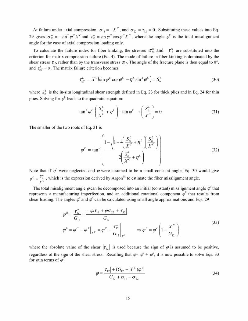
At failure under axial compression, CX−=11σ , and 01222 == τσ . Substituting these values into Eq. 29 gives CCm Xϕσ 2
22 sin−= and CCCm Xϕϕτ cossin12 = , where the angle ϕC is the total misalignment angle for the case of axial compression loading only.
To calculate the failure index for fiber kinking, the stresses mm1222 and τσ are substituted into the
criterion for matrix compression failure (Eq. 4). The mode of failure in fiber kinking is dominated by the shear stress τ12, rather than by the transverse stress σ22. The angle of the fracture plane is then equal to 0°, and 0=T
effτ . The matrix failure criterion becomes
( ) Lis
CLCCCLeff SX =−= ϕηϕϕτ 2sincossin (30)
where LisS is the in-situ longitudinal shear strength defined in Eq. 23 for thick plies and in Eq. 24 for thin
plies. Solving for ϕC leads to the quadratic equation:
0tantan2 =
+−
+ C
LisCL
C
LisC
XS
XS ϕηϕ (31)
The smaller of the two roots of Eq. 31 is
+
+−−
= −
LC
Lis
C
LisL
C
Lis
C
XS
XS
XS
η
ηϕ
2
411tan 1 (32)
Note that if ηL were neglected and ϕ were assumed to be a small constant angle, Eq. 30 would give
C
LisC
XS
≈ϕ , which is the expression derived by Argon38 to estimate the fiber misalignment angle.
The total misalignment angle ϕ can be decomposed into an initial (constant) misalignment angle ϕ0 that represents a manufacturing imperfection, and an additional rotational component ϕR that results from shear loading. The angles ϕ0 and ϕR can be calculated using small angle approximations and Eqs. 29
−=⇒−=−=
++−==
12
0
12
120
12
122211
12
12
1GX
G
GGC
C
X
mC
X
RC
mR
CC ϕϕτϕϕϕϕ
τϕσϕστϕ (33)
where the absolute value of the shear 12τ is used because the sign of ϕ is assumed to be positive, regardless of the sign of the shear stress. Recalling that ϕ= ϕ0 + ϕR, it is now possible to solve Eqs. 33 for ϕ in terms of ϕC.
221112
1212 )(σσ
ϕτϕ
−+−+
=G
XG CC
(34)

16
Fiber compression failure by formation of a kink band is predicted using the stresses from Eq. 29 and the failure criterion for matrix tension or matrix compression. For matrix compression ( 022 <mσ ), the criterion is the Mohr-Coulomb criterion given in Eq. 4, with α=0° and 0=T
effτ . The criterion for fiber kinking becomes:
LaRC03 #4 12212 ≤+
= Lis
mLm
F SFI
σητ (35)
For fiber compression with matrix tension, the transformed stresses of Eq. 29 are substituted into the matrix tensile failure criterion given in Eq. 20 to yield the following criterion for fiber kinking:
LaRC03 #5 ( ) 112
12
2
2222 ≤
+
+
−= L
is
m
Tis
m
Tis
m
F Sτ
Yσg
YσgFI (36)
It is interesting to note that for 022 =σ , the fiber failure criterion in Eq. 35 becomes
121
1with1 21211 >
−−=≤+−=
ϕηϕτσ
LLCF kSkX
FI (37)
The linear interaction between σ11 and τ12 in Eq. 37 is identical to the form used by Edge7 for the WWFE. For T300/914C, Edge suggests using an empirical value of k=1.5. However, Edge also indicates that other researchers have shown excellent correlation with experimental results with k=1. Using the WWFE strength values of XC=900 MPa, SL=80 MPa, YC=200 MPa, an assumed fracture angle in transverse compression of 53°, and Eqs. 11 and 32, we get: ηL=0.304, ϕC=5.3°. With the approximation ϕ≅ϕC, Eq. 37 gives k=1.07.
LaRC03 Criterion for Matrix Damage in Biaxial Compression In the presence of high transverse compression combined with moderate fiber compression, matrix
damage can occur without the formation of kink bands or damage to the fibers. This matrix damage mode is calculated using the stresses in the misaligned frame in the failure criterion in Eq. 4, which gives:
LaRC03 #6 122
≤
+
= L
is
mLeff
T
mTeff
M Sτ
Sτ
FI (38)
where the effective shear stresses mLeff
mTeff ττ and are defined as in Eq. 6, but in terms of the in-plane
stresses in the misalignement frame, which are defined in Eqs. 29.
)cos(cos
)cos(sincos
2212
22
ασητατ
αηααστmLmmL
eff
TmmTeff
+=
−−= (39)
As for all matrix compressive failures herein, the stresses mLeff
mTeff ττ and are functions of the fracture
angle α, which must be determined iteratively.

17
Verification Problems
Example 1. Unidirectional 0° E-glass/MY750 epoxy
All of the failure modes represented by the six LaRC03 criteria (Eqs. 4, 20, 28, 35, 36 and 38, and summarized in the Appendix) can be represented as a failure envelope in the σ11-σ22 plane. An example is shown in Fig. 10 for a 0° E-glass/MY750 epoxy lamina. Puck’s analysis results, which showed the best correlation with experimental results in the WWFE3, is also shown for comparison. In the figure, there is good agreement between LaRC03 and Puck in all quadrants except biaxial compression, where LaRC03 predicts an increase of the axial compressive strength with increasing transverse compression. Testing for biaxial loads presents a number of complexities, and experimental results are rare. However, Waas et al.43 report a number of references in which multiaxial compression was studied by superposing a hydrostatic pressure in addition to the compressive loading. For all materials considered, there is a significant increase in compressive strength with increasing pressure. In particular, the results of Wronsky and Parry44 on glass/epoxy show a strength increase of 3.3 MPa per MPa of hydrostatic pressure, which gives an actual strength increase of 4.3 MPa per MPa of applied transverse biaxial stress. More recently, Sigley et al.45 found 32% to 71% increases in compressive strength per 100 MPa superposed pressure. The results of Wronsky and Sigley can be compared qualitatively to the 4.3 MPa/MPa increase in compressive strength for the plane stress failure envelope in Fig. 10.
1500 500 0 1000 1500
50
50
100
150
5001000
Puck
FI ,M LaRC03 #1
FI ,M LaRC03 #6
FI ,M LaRC03 #2
FI ,F LaRC03 #3FI ,F LaRC03 #4
FI ,F LaRC03 #5
σ11, MPa
σ =−11 Yc
σ22, MPa
σ =022m
Figure 10. Biaxial σ11-σ22 failure envelope of 0° E-glass/MY750 epoxy lamina.
Example 2. Unidirectional composite E-Glass/LY556
A comparison of results from various failure criteria with the experimental results in the σ22-τ12 stress plane obtained from the WWFE46 is shown in Fig. 11. It can be observed that within the positive range of σ22, all the quadratic failure criteria and LaRC03 give satisfactory results. Since the Maximum Stress criterion does not prescribe interactions between stress components, its failure envelope is rectangular. The most interesting behavior develops when σ22 becomes compressive. Hashin’s 1973 criterion gives an

18
elliptical envelope with diminishing τ12 as the absolute value of compressive σ22 increases, while the experimental data shows a definite trend of shear strength increase as σ22 goes into compression.
The envelope for Hashin’s 1980 criteria was calculated using a transverse strength obtained from Eq. 10, and it provides a modest improvement in accuracy compared to the 1973 criterion. Of the criteria shown in Fig. 11, Sun (Eq. 1), LaRC03 #1 (Eq. 4), and Puck (Eq. 2) capture the shear strength increase at the initial stage of compressive σ22. The failure envelope for Sun’s criterion (Eq. 1) was calculated using ηL=0.336 from Eq. 11. The results indicate a significant improvement over Hashin’s criteria. An even better fit would have been achieved using a higher value for ηL. Puck’s envelope, which was extracted from the 2002 WWFE6, appears to be the most accurate, but it relies on fitting parameters based on the same test data. The LaRC03 curve uses the stiffnesses and strengths shown in Table 2, an assumed α0=53°, and no other empirical or fitting parameter. In the case of matrix tension, Puck’s predicted failure envelope is nearly identical to LaRC03 #2.
Table 2. Properties of E-Glass/LY55646 ( MPa)
E11 E22 G12 νννν12 YT YC SL 53,480 17,700 5,830 0.278 36 138 61
-150 -50 0 50
50
100Puck ‘02WWFE test ‘02
-100
LaRC03 #1
LaRC03 #2
Hashin ‘73
Sun ‘96
Hashin ‘80Hashin
Max. stress
τ12
σ22
, MPa
, MPa
Figure 11. Failure envelopes and WWFE test data2 for unidirectional composite E-Glass/LY556.
Example 3. Cross-ply laminates
Shuart47 studied the compression failure of [±θ]s laminates and found that for θ <15°, the dominant failure mode in these laminates is interlaminar shearing; for 15°<θ <50°, it is in-plane matrix shearing; and for θ >50°, it is matrix compression. Fiber scissoring due to matrix material nonlinearity caused the switch in failure mode from in-plane matrix shearing to matrix compression failure at larger lamination angles. The material properties shown in Table 3 were used for the analysis. The angle α0 was assumed to be a typical 53°. For other lamination angles, the fracture angle was obtained by searching numerically for the angle that maximizes the failure criterion in Eq. 4. The in-situ shear strength did not need to be calculated since it is given by Shuart47 as MPaS L
is 1.95= .
The results in Fig. 12 indicate that the predicted strengths using LaRC03 criteria correlate well with the experimental results. The compressive strength predicted using Hashin 1973 criteria is also shown in Fig.

19
12. For θ <20°, the Hashin criteria result in an overprediction of the failure load because the criterion does not account for the effect of inplane shear on fiber failure. For lamination angles near 70°, the use of the Hashin criteria result in an underprediction of the failure load because the criteria do not account for the increase in shear strength caused by transverse compression. All of these effects are represented by the LaRC03 criteria, which results in a good correlation between the calculated and experimental values.
Table 3. Properties of AS4-350247 ( MPa)
E11 E22 G12 νννν12 XC YC LisS
127,600 11,300 6,00 0.278 1045 244 95.1 C
ompr
essi
ve s
tress
, MPa
Lamination angle, degrees
Test, Shuart ‘89
Hashin ‘73
LaRC03
α0=530α=440α=00
Figure 12. Compressive strength as a function of ply orientation for [±θ]s AS4/3502 laminates.
Concluding Remarks
The results of the recently concluded World Wide Failure Exercise indicate that the existing knowledge on failure mechanisms needs further development. Many of the existing failure models could not predict the experimental response within a tolerable limit. In fact, differences of up to an order of magnitude between the predicted and experimental values were not uncommon. In this paper, a new set of six physically-based failure criteria devoid of empirical variables is proposed. The criteria for matrix and fiber compression failure are based on a Mohr-Coulomb interaction of the stresses associated with the plane of fracture. Failure envelopes for unidirectional laminates in the σ11-σ22 and σ22-τ12 stress planes were calculated, as well as the compressive strength of cross-ply laminates. The predicted failure envelopes indicate good correlation with experimental results. The proposed criteria, referred to as LaRC03, represent a significant improvement over the commonly used Hashin criteria, especially in the cases of matrix or fiber failure in compression.
20
References
1) Soden, P.D., Hinton, M.J., and Kaddour, A.S., "A Comparison of the Predictive Capabilities of Current Failure Theories for Composite Laminates," Composites Science and Technology, Vol. 58, No. 7, 1998, pp. 1225-1254.
2) Soden, P.D., Hinton, M.J., and Kaddour, A.S., "Biaxial Test Results for Strength and Deformation of a Range of E-Glass and Carbon Fibre Reinforced Composite Laminates: Failure Exercise Benchmark Data," Composites Science and Technology, Vol. 62, No. 12-13, 2002, pp. 1489-1514.
3) Hinton, M.J., Kaddour, A.S., and Soden, P.D., "A Comparison of the Predictive Capabilities of Current Failure Theories for Composite Laminates, Judged against Experimental Evidence," Composites Science and Technology, Vol. 62, No. 12-13, 2002, pp. 1725-1797.
4) Hinton, M.J., and Soden, P.D., "Predicting Failure in Composite Laminates: The Background to the Exercise," Composites Science and Technology, Vol. 58, No. 7, 1998, pp. 1001-1010.
5) Puck, A., and Schurmann, H., "Failure Analysis of FRP Laminates by Means of Physically Based Phenomenological Models," Composites Science and Technology, Vol. 58, No. 7, 1998, pp. 1045-1067.
6) Puck, A., and Schurmann, H., "Failure Analysis of FRP Laminates by Means of Physically Based Phenomenological Models," Composites Science and Technology, Vol. 62, No. 12-13, 2002, pp. 1633-1662.
7) Edge, E.C., "Stress-Based Grant-Sanders Method for Predicting Failure of Composite Laminates," Composites Science and Technology, Vol. 58, No. 7, 1998, pp. 1033-1041.
8) París, F., "A Study of Failure Criteria of Fibrous Composite Materials," NASA/CR-2001-210661, Hampton, VA, March 2001.
9) Hashin, Z., and Rotem, A., "A Fatigue Criterion for Fiber-Reinforced Materials," Journal of Composite Materials, Vol. 7, 1973, pp. 448-464.
10) Hashin, Z., "Failure Criteria for Unidirectional Fiber Composites," Journal of Applied Mechanics, Vol. 47, 1980, pp. 329-334.
11) Sun, C.T., Quinn, B.J., and Oplinger, D.W., "Comparative Evaluation of Failure Analysis Methods for Composite Laminates," DOT/FAA/AR-95/109, 1996.
12) Shahid, I., and Chang, F.-K., "An Accumulative Damage Model for Tensile and Shear Failures of Laminated Composite Plates," Journal of Composite Materials, Vol. 29, 1995, pp. 926-981.
13) Salençon, J., Handbook of Continuum Mechanics: General Concepts, Thermoelasticity, Springer, Berlin; New York, 2001.
14) Kawabata, S., "Strength of Epoxy Resin under Multiaxial Stress Field," Proceedings of the ICCM-IV, Tokyo, 1982, pp. 161-168.
15) Boehler, J.P., and Raclin, J., "Failure Criteria for Glass-Fiber Reinforced Composites under Confining Pressure," J. Struct. Mech., Vol. 13, No. 3 & 4, 1985, pp. 371-392.
16) Taliercio, A., and Sagramoso, P., "Uniaxial Strength of Polymeric-Matrix Fibrous Composites Predicted through a Homogenization Approach," International Journal of Solids and Structures, Vol. 32, No. 14, 1995, pp. 2095-2123.
17) DiLandro, L., and Pegoraro, M., "Carbon Fibre-Thermoplastic Matrix Adhesion," Journal of Material Science, Vol. 22, 1987, pp. 1980-1986.
18) Larson, M.C., and Miles, H.F., "On the Effects of Friction, Roughness and Toughness on Interfacial Sliding in Brittle Composites," Mechanics of Materials, Vol. 27, No. 2, 1998, pp. 77-89.
19) Parvizi, A., Garrett, K., and Bailey, J., "Constrained Cracking in Glass Fibre-Reinforced Epoxy Cross-Ply Laminates," Journal of Material Science, Vol. 13, 1978, pp. 195-201.
20) Wang, A.S.D., "Fracture Mechanics of Sublaminate Cracks in Composite Materials," Composites Technology Review, Vol. 6, No. 2, 1984, pp. 45-62.
21) Tan, S.C., and Nuismer, R.J., "A Theory for Progressive Matrix Cracking in Composite Laminates," Journal of Composite Materials, Vol. 23, 1989, pp. 1029-1047.

21
22) Talreja, R., "Transverse Cracking and Stiffness Reduction in Composite Laminates," Journal of Composite Materials, Vol. 19, 1985, pp. 355-375.
23) Allen, D.H., Harris, C.E., and Groves, S.E., "A Thermomechanical Constitutive Theory for Elastic Composites with Distributed Damage- I. Theoretical Development," International Journal of Solids and Structures, Vol. 23, No. 9, 1987, pp. 1301-1318.
24) Allen, D.H., Harris, C.E., and Groves, S.E., "A Thermomechanical Constitutive Theory for Elastic Composites with Distributed Damage- II. Application to Matrix Cracking in Laminated Composites," International Journal of Solids and Structures, Vol. 23, No. 9, 1987, pp. 1319-1338.
25) Talreja, R., Yalvac, S., Yats, L.D., and Wetters, D.G., "Transverse Cracking and Stiffness Reduction in Cross Ply Laminates of Different Matrix Toughness," Journal of Composite Materials, Vol. 26, No. 11, 1992, pp. 1644-1663.
26) Dvorak, G.J., and Laws, N., "Analysis of Progressive Matrix Cracking in Composite Laminates II. First Ply Failure," Journal of Composite Materials, Vol. 21, 1987, pp. 309-329.
27) Chang, F.-K., and Chen, M.-H., "The In Situ Ply Shear Strength Distributions in Graphite/Epoxy Laminated Composites," Journal of Composite Materials, Vol. 21, 1987, pp. 708-733.
28) Flaggs, D.L., and Kural, M.H., "Experimental Determination of the In Situ Transverse Lamina Strength in Graphite/Epoxy Laminates," Journal of Composite Materials, Vol. 16, 1982, pp. 103-116.
29) Laws, N., and Dvorak, G.J., "Progressive Transverse Cracking in Composite Laminates," Journal of Composite Materials, Vol. 22, 1988, pp. 900-919.
30) Hahn, H.T., and Johannesson, T., "Fracture of Unidirectional Composites: Theory and Applications," Mechanics of Composite Materials, G.J. Dvorak ed., AMD, 1983, pp. 135-142.
31) Liu, K.-S., and Tsai, S.W., "A Progressive Quadratic Failure Criterion for a Laminate," Composites Science and Technology, Vol. 58, No. 7, 1998, pp. 1023-1032.
32) Wu, E.M., and Reuter, R.C.J., "Crack Extension in Fiberglass Reinforced Plastics and a Critical Examination of the General Fracture Criterion," University of Illinois, Theor. and Appl. Mech. Report No. 275, Urbana-Champaign, 1965.
33) Leguillon, D., "Strength or Toughness? A Criterion for Crack Onset at a Notch," European Journal of Mechanics - A/Solids, Vol. 21, No. 1, 2002, pp. 61-72.
34) Tada, H., Paris, P., C., and Irwin, G.R., The Stress Analysis of Cracks Handbook, 3rd. ed, American Society of Mechanical Engineers, New York, 2000.
35) Fleck, N.A., and Liu, D., "Microbuckle Initiation from a Patch of Large Amplitude Fibre Waviness in a Composite under Compression and Bending," European Journal of Mechanics - A/Solids, Vol. 20, No. 1, 2001, pp. 23-37.
36) Soutis, C., Smith, F.C., and Matthews, F.L., "Predicting the Compressive Engineering Performance of Carbon Fibre-Reinforced Plastics," Composites Part A: Applied Science and Manufacturing, Vol. 31, No. 6, 2000, pp. 531-536.
37) Schultheisz, C.R., and Waas, A.M., "Compressive Failure of Composites, Part 1: Testing and Micromechanical Theories," Progress in Aerospace Sciences, Vol. 32, 1996, pp. 1-42.
38) Argon, A.S., Fracture of Composites, Treatise of Materials Science and Technology, Vol. 1, Academic Press, New York, 1972.
39) Budiansky, B., Fleck, N.A., and Amazigo, J.C., "On Kink-Band Propagation in Fiber Composites," Journal of the Mechanics and Physics of Solids, Vol. 46, No. 9, 1998, pp. 1637-1653.
40) Berg, C.A., and Salama, M., "Fatigue of Graphite Fibre-Reinforced Epoxy in Compression," Fibre Science and Technology, Vol. 6, No. 2, 1973, pp. 79-118.
41) Schapery, R.A., "Prediction of Compressive Strength and Kink Bands in Composites Using a Work Potential," International Journal of Solids and Structures, Vol. 32, No. 6-7, 1995, pp. 739-765.
42) Potter, D.S., Gupta, V., and Hauert, S., "Effects of Specimen Size and Sample Aspect Ratio on the Compressive Strength of Graphite/Epoxy Laminates," Composites Science and Technology, Vol. 60, No. 12-13, 2000, pp. 2525-2538.
22
43) Waas, A.M., and Schultheisz, C.R., "Compressive Failure of Composites, Part II: Experimental Studies," Progress in Aerospace Sciences, Vol. 32, No. 1, 1996, pp. 43-78.
44) Wronski, A.S., and Parry, T.V., "Compressive Failure and Kinking in Uniaxially Aligned Glass-Resin Composite under Superposed Hydrostatic Pressure," Journal of Material Science, Vol. 17, 1982, pp. 3656-3662.
45) Sigley, R.H., Wronski, A.S., and Parry, T.V., "Axial Compressive Failure of Glass-Fibre Polyester Composites under Superposed Hydrostatic Pressure: Influence of Fibre Bundle Size," Composite Science and Technology, Vol. 43, 1992, pp. 171-183.
46) Soden, P.D., Hinton, M.J., and Kaddour, A.S., "Lamina Properties, Lay-up Configurations and Loading Conditions for a Range of Fibre-Reinforced Composite Laminates," Composites Science and Technology, Vol. 58, No. 7, 1998, pp. 1011-1022.
47) Shuart, M.J., "Failure of Compression-Loaded Multidirectional Composite Laminates," AIAA Journal, Vol. 27, No. 9, 1989, pp. 1274-1279.
23
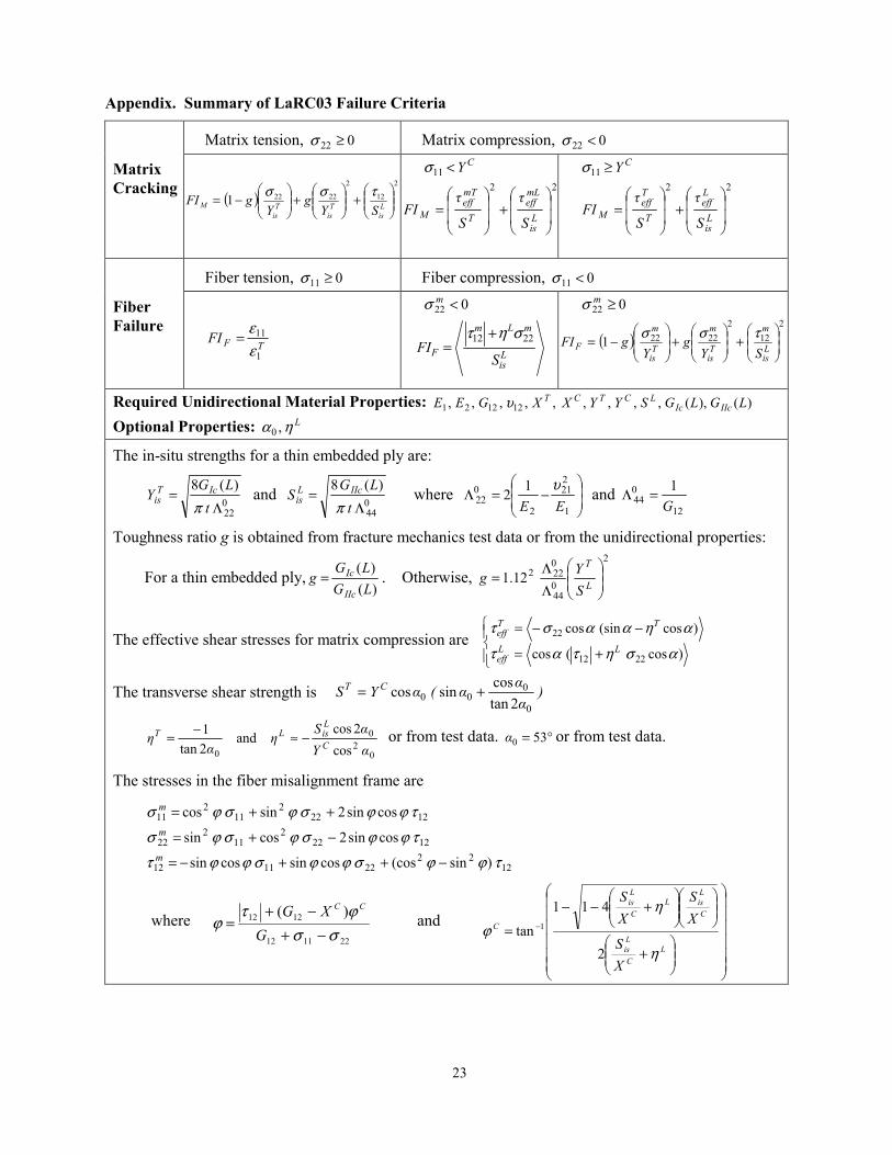
Appendix. Summary of LaRC03 Failure Criteria
Matrix tension, 022 ≥σ Matrix compression, 022 <σ Matrix Cracking
( )2
12
2
22221
+
+
−= L
isT
isT
isM SY
gY
gFI τσσ
CY<11σ 22
+
=
Lis
mLeff
T
mTeff
MS
τ
S
τFI
CY≥11σ 22
+
=
Lis
Leff
T
Teff
MS
τ
S
τFI
Fiber tension, 011 ≥σ Fiber compression, 011 <σ Fiber Failure
TFFI1
11
εε
=
022 <mσ
Lis
mLm
F SFI
2212 σητ +=
022 ≥mσ
( )2
122
22221
+
+
−= L
is
m
Tis
m
Tis
m
F SYg
YgFI τσσ
Required Unidirectional Material Properties: )(),(,,,,,,,,, 121221 LGLGSYYXXGEE IIcIcLCTCTυ
Optional Properties: Lηα ,0
The in-situ strengths for a thin embedded ply are:
022
)(8Λ
=t
LGY IcT
is π and 0
44
)(8Λ
=t
LGS IIcL
is π where
−=Λ
1
221
2
022
12EE
υ and 12
044
1G
=Λ
Toughness ratio g is obtained from fracture mechanics test data or from the unidirectional properties:
For a thin embedded ply,)()(
LGLG
gIIc
Ic= . Otherwise, 2
044
022212.1
ΛΛ= L
T
SYg
The effective shear stresses for matrix compression are
+=
−−=
)cos(cos
)cos(sincos
2212
22
ασητατ
αηααστLL
eff
TTeff
The transverse shear strength is )ααα(αYS CT
0
000 2tan
cossincos +=
02
0
0 cos2cos
and2tan1
αYαS
ηα
η C
LisLT −≈−= or from test data. °= 530α or from test data.
The stresses in the fiber misalignment frame are
1222
221112
12222
112
22
12222
112
11
)sin(coscossincossin
cossin2cossin
cossin2sincos
τϕϕσϕϕσϕϕτ
τϕϕσϕσϕσ
τϕϕσϕσϕσ
−++−=
−+=
++=
m
m
m
where 221112
1212 )(σσ
ϕτϕ
−+−+
=G
XG CC
and
+
+−−
= −
LC
Lis
C
LisL
C
Lis
C
XS
XS
XS
η
ηϕ
2
411
tan 1

REPORT DOCUMENTATION PAGE Form ApprovedOMB No. 0704-0188
2. REPORT TYPE
Technical Memorandum 4. TITLE AND SUBTITLE
Failure Criteria for FRP Laminates in Plane Stress5a. CONTRACT NUMBER
6. AUTHOR(S)
Davila, Carlos G.; Camanho, Pedro P.
7. PERFORMING ORGANIZATION NAME(S) AND ADDRESS(ES)
NASA Langley Research CenterHampton, VA 23681-2199
9. SPONSORING/MONITORING AGENCY NAME(S) AND ADDRESS(ES)
National Aeronautics and Space AdministrationWashington, DC 20546-0001
8. PERFORMING ORGANIZATION REPORT NUMBER
L-19012
10. SPONSOR/MONITOR'S ACRONYM(S)
NASA
13. SUPPLEMENTARY NOTESAn electronic version can be found at http://techreports.larc.nasa.gov/ltrs/ or http://ntrs.nasa.gov
12. DISTRIBUTION/AVAILABILITY STATEMENTUnclassified - UnlimitedSubject Category 39Availability: NASA CASI (301) 621-0390 Distribution: Standard
19a. NAME OF RESPONSIBLE PERSON
STI Help Desk (email: [email protected])
14. ABSTRACT
A new set of six failure criteria for fiber reinforced polymer laminates is described. Derived from Dvorak's fracture mechanics analyses of cracked plies and from Puck's action plane concept, the physically-based criteria, denoted LaRC03, predict matrix and fiber failure accurately without requiring curve-fitting parameters. For matrix failure under transverse compression, the fracture plane is calculated by maximizing the Mohr-Coulomb effective stresses. A criterion for fiber kinking is obtained by calculating the fiber misalignment under load, and applying the matrix failure criterion in the coordinate frame of the misalignment. Fracture mechanics models of matrix cracks are used to develop a criterion for matrix in tension and to calculate the associated in-situ strengths. The LaRC03 criteria are applied to a few examples to predict failure load envelopes and to predict the failure mode for each region of the envelope. The analysis results are compared to the predictions using other available failure criteria and with experimental results. Predictions obtained with LaRC03 correlate well with the experimental results.
15. SUBJECT TERMS
Composites; Cracks; Failure criteria; Fiber kinking; Fracture mechanics
18. NUMBER OF PAGES
28
19b. TELEPHONE NUMBER (Include area code)
(301) 621-0390
a. REPORT
U
c. THIS PAGE
U
b. ABSTRACT
U
17. LIMITATION OF ABSTRACT
UU
Prescribed by ANSI Std. Z39.18Standard Form 298 (Rev. 8-98)
3. DATES COVERED (From - To)
5b. GRANT NUMBER
5c. PROGRAM ELEMENT NUMBER
5d. PROJECT NUMBER
5e. TASK NUMBER
5f. WORK UNIT NUMBER
23-719-55
11. SPONSOR/MONITOR'S REPORT NUMBER(S)
NASA/TM-2003-212663
16. SECURITY CLASSIFICATION OF:
The public reporting burden for this collection of information is estimated to average 1 hour per response, including the time for reviewing instructions, searching existing data sources, gathering and maintaining the data needed, and completing and reviewing the collection of information. Send comments regarding this burden estimate or any other aspect of this collection of information, including suggestions for reducing this burden, to Department of Defense, Washington Headquarters Services, Directorate for Information Operations and Reports (0704-0188), 1215 Jefferson Davis Highway, Suite 1204, Arlington, VA 22202-4302. Respondents should be aware that notwithstanding any other provision of law, no person shall be subject to any penalty for failing to comply with a collection of information if it does not display a currently valid OMB control number.PLEASE DO NOT RETURN YOUR FORM TO THE ABOVE ADDRESS.
1. REPORT DATE (DD-MM-YYYY)
11 - 200301-