Embed Size (px)
Citation preview
9609 Indianapolis Road Fort Wayne, IN 46809 Tel: 260-747-4154 Fax: 260-747-0398 Email: [email protected] Web site: www.fwmetals.com/
�
Presented at ASM Materials and Processes for Medical Device Conference and Exposition (MPMD), Boston, MA November 2005
Fatigue Failure Analysis of Enhanced 35N LT®
Lawrence Kay, Raymond Bouthot Fort Wayne Metals Research Products Corp., Fort Wayne, Indiana, USA
Abstract MP35N® (ASTM F 562, UNS R30035) is the most common alloy used for leads in pacing devices. The unique requirements of this application require the balance of biocompatibility, corrosion resistance, and high fatigue strength offered by this alloy system. Drawn Filled Tube (DFT®) has been produced from this allow system to offer a low resistance material. This composite wire uses an outer layer of ASTM F 562 (cobalt-nickel-chromium-molybdenum alloy) material for strength and corrosion resistance combined with a core material of silver to provide high conductivity properties. Previous studies of MP35N and Drawn Filled Tube (DFT®) have been conducted to analyze the effect of titanium content of the melt. The new enhanced chemistry of 35N LT® provides measurable improvements in surface finish and dramatic improvements in fatigue life. These improvements have been achieved while maintaining conformance to the requirements of the applicable material standards. This detailed study of the fatigue fractures uses Scanning Electron Microscopy (SEM) analysis to determine the cause of the failures in both material systems. It will be shown that the optimized process of 35N LT® accomplishes the desired reduction in Titanium Nitride based inclusions.
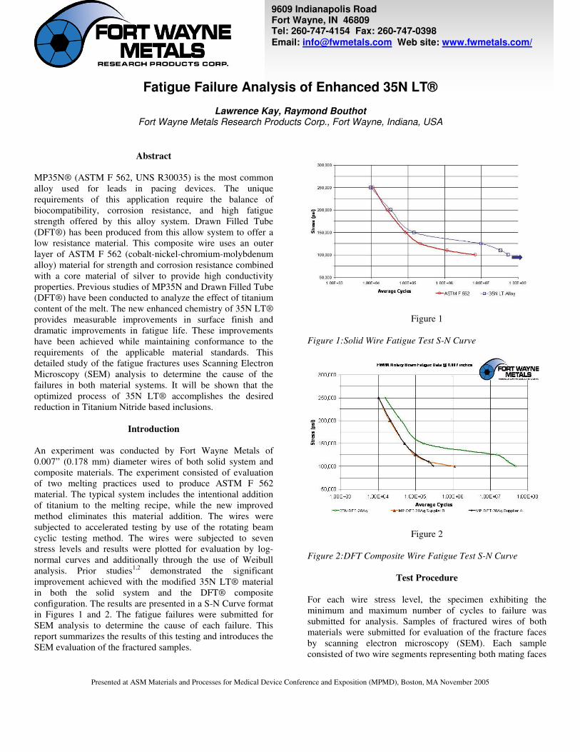
Introduction An experiment was conducted by Fort Wayne Metals of 0.007” (0.178 mm) diameter wires of both solid system and composite materials. The experiment consisted of evaluation of two melting practices used to produce ASTM F 562 material. The typical system includes the intentional addition of titanium to the melting recipe, while the new improved method eliminates this material addition. The wires were subjected to accelerated testing by use of the rotating beam cyclic testing method. The wires were subjected to seven stress levels and results were plotted for evaluation by log-normal curves and additionally through the use of Weibull analysis. Prior studies1,2 demonstrated the significant improvement achieved with the modified 35N LT® material in both the solid system and the DFT® composite configuration. The results are presented in a S-N Curve format in Figures 1 and 2. The fatigue failures were submitted for SEM analysis to determine the cause of each failure. This report summarizes the results of this testing and introduces the SEM evaluation of the fractured samples.
Figure 1 Figure 1:Solid Wire Fatigue Test S-N Curve
Figure 2 Figure 2:DFT Composite Wire Fatigue Test S-N Curve
Test Procedure For each wire stress level, the specimen exhibiting the minimum and maximum number of cycles to failure was submitted for analysis. Samples of fractured wires of both materials were submitted for evaluation of the fracture faces by scanning electron microscopy (SEM). Each sample consisted of two wire segments representing both mating faces
9609 Indianapolis Road Fort Wayne, IN 46809 Tel: 260-747-4154 Fax: 260-747-0398 Email: [email protected] Web site: www.fwmetals.com/
�
Presented at ASM Materials and Processes for Medical Device Conference and Exposition (MPMD), Boston, MA November 2005
of the fracture. Both halves of each wire fracture sample were examined by scanning electron microscopy (SEM) using secondary electron imaging (SEI). SEI reveals fine surface morphology. The fractures were examined in an orientation normal to the wire length and in tilted orientations to view the wire surface near the fracture. In BEI, the brightness of sample features is proportional to the atomic weight of the elements constituting those features. Thus, heavier elements are displayed as brighter than lighter elements; e.g., metals appear brighter than most nonmetallic inclusions. A BEI micrograph of each fracture half for each sample was acquired. Additionally, SEM, qualitative chemical analyses were performed by energy dispersive x-ray spectroscopy (EDS) of one of the ASTM F-562 samples.
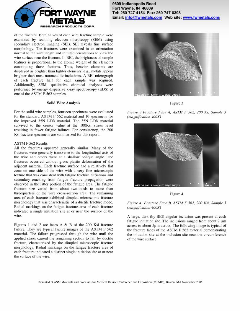
Solid Wire Analysis For the solid wire samples, fourteen specimens were evaluated for the standard ASTM F 562 material and 10 specimens for the improved 35N LT® material. The 35N LT® material survived to the censor value at the 100Ksi stress level resulting in fewer fatigue failures. For consistency, the 200 Ksi fracture specimens are summarized for this report. ASTM F 562 Results All the fractures appeared generally similar. Many of the fractures were generally transverse to the longitudinal axis of the wire and others were at a shallow oblique angle. The fractures occurred without gross plastic deformation of the adjacent material. Each fracture surface had a relatively flat zone on one side of the wire with a very fine microscopic texture that was consistent with fatigue fracture. Striations and secondary cracking from fatigue fracture propagation were observed in the latter portion of the fatigue area. The fatigue fracture size varied from about two-thirds to more than threequarters of the wire cross-section area. The remaining area of each fracture exhibited dimpled microscopic fracture morphology that was characteristic of a ductile fracture mode. Radial markings on the fatigue fracture area of each fracture indicated a single initiation site at or near the surface of the wire. Figures 1 and 2 are faces A & B of the 200 Ksi fracture failure. They are typical failure images of the ASTM F 562 material. The failure progressed through the wire until the applied stress caused the remaining section to fail by ductile fracture, characterized by the dimpled microscopic fracture morphology. Radial markings on the fatigue fracture area of each fracture indicated a distinct single initiation site at or near the surface of the wire.
Figure 3 Figure 3:Fracture Face A, ASTM F 562, 200 Ks, Sample 3 (magnification 400X)
Figure 4
Figure 4: Fracture Face B, ASTM F 562, 200 Ksi, Sample 3 (magnificaiton 400X) A large, dark (by BEI) angular inclusion was present at each fatigue initiation site. The inclusions ranged from about 2 µm across to about 5µm across. The following image is typical of the fracture faces of the ASTM F 562 material demonstrating the initiation site at the inclusion site near the circumference of the wire surface.
9609 Indianapolis Road Fort Wayne, IN 46809 Tel: 260-747-4154 Fax: 260-747-0398 Email: [email protected] Web site: www.fwmetals.com/
�
Presented at ASM Materials and Processes for Medical Device Conference and Exposition (MPMD), Boston, MA November 2005
Figure 5 Figure 5: Fracture Face B, ASTM F 562, 200 Ksi, Sample 3 (magnification 3000X) EDS analysis of the dark inclusions at the fatigue initiation sites detected primarily titanium and nitrogen, Figure 6. This composition indicated that the inclusions were titanium nitride. The angular shape of the inclusions is also consistent with titanium nitride particles.
Figure 6 Figure 6: EDS spectrum for typical fracture origin inclusion, sample 3 fracture face A. 35N LT Results All the fractures appeared generally similar. The fracture features were consistent with a progressive fatigue fracture mode. Fracture originated along the outer circumference of the wire and progressed across the wire section until the applied tensile stress caused the remaining section to fail by ductile fracture. No significant material anomalies were observed at the fracture origins for the samples. No nonmetallic inclusions were observed for the fracture origins for any of the samples.
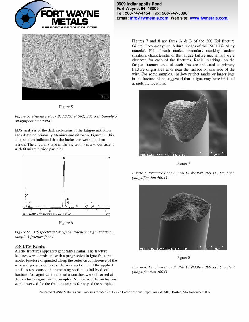
Figures 7 and 8 are faces A & B of the 200 Ksi fracture failure. They are typical failure images of the 35N LT Alloy material. Faint beach marks, secondary cracking, and/or striations characteristic of the fatigue failure mechanism were observed for each of the fractures. Radial markings on the fatigue fracture area of each fracture indicated a primary fracture origin area at or near the surface on one side of the wire. For some samples, shallow ratchet marks or larger jogs in the fracture plane suggested that fatigue may have initiated at multiple locations.
Figure 7
Figure 7: Fracture Face A, 35N LT Alloy, 200 Ksi, Sample 3 (magnification 400X)
Figure 8
Figure 8: Fracture Face B, 35N LT Alloy, 200 Ksi, Sample 3 (magnification 400X)
9609 Indianapolis Road Fort Wayne, IN 46809 Tel: 260-747-4154 Fax: 260-747-0398 Email: [email protected] Web site: www.fwmetals.com/
�
Presented at ASM Materials and Processes for Medical Device Conference and Exposition (MPMD), Boston, MA November 2005
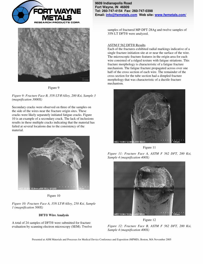
Figure 9
Figure 9: Fracture Face B, 35N LT Alloy, 200 Ksi, Sample 3 (magnification 3000X) Secondary cracks were observed on three of the samples on the side of the wires near the fracture origin sites. These cracks were likely separately initiated fatigue cracks. Figure 10 is an example of a secondary crack. The lack of inclusions results in these multiple cracks indicating that the material has failed at several locations due to the consistency of the material.
Figure 10
Figure 10: Fracture Face A, 35N LT Alloy, 250 Ksi, Sample 1 (magnification 500X)
DFT® Wire Analysis A total of 24 samples of DFT® were submitted for fracture evaluation by scanning electron microscopy (SEM). Twelve
samples of fractured MP-DFT-28Ag and twelve samples of 35N LT DFT® were analyzed. ASTM F 562 DFT® Results Each of the fractures exhibited radial markings indicative of a single fracture initiation site at or near the surface of the wire. The microscopic fracture features in the origin area for each wire consisted of a ridged texture with fatigue striations. This fracture morphology is characteristic of a fatigue fracture mechanism. The fatigue fracture propagated across over one half of the cross section of each wire. The remainder of the cross section for the tube section had a dimpled fracture morphology that was characteristic of a ductile fracture mechanism.
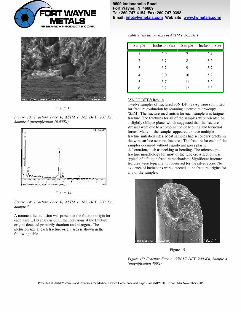
Figure 11
Figure 11: Fracture Face A, ASTM F 562 DFT, 200 Ksi, Sample 4 (magnification 400X)
Figure 12
Figure 12: Fracture Face B, ASTM F 562 DFT, 200 Ksi, Sample 4 (magnification 400X)
9609 Indianapolis Road Fort Wayne, IN 46809 Tel: 260-747-4154 Fax: 260-747-0398 Email: [email protected] Web site: www.fwmetals.com/
�
Presented at ASM Materials and Processes for Medical Device Conference and Exposition (MPMD), Boston, MA November 2005
Figure 13
Figure 13: Fracture Face B, ASTM F 562 DFT, 200 Ksi, Sample 4 (magnification 10,000X)
Figure 14
Figure 14: Fracture Face B, ASTM F 562 DFT, 200 Ksi, Sample 4 A nonmetallic inclusion was present at the fracture origin for each wire. EDS analysis of all the inclusions at the fracture origins detected primarily titanium and nitrogen.. The inclusion size at each fracture origin area is shown in the following table.
Table 1: Inclusion sizes of ASTM F 562 DFT
Sample Inclusion Size Sample Inclusion Size
1 3.9 7 2.4
2 3,7 8 3.2
3 3.7 9 3.7
4 3.0 10 5.2
5 3.7 11 3.2
6 3.2 12 3.3
35N LT DFT® Results Twelve samples of fractured 35N-DFT-28Ag were submitted for fracture evaluation by scanning electron microscopy (SEM). The fracture mechanism for each sample was fatigue fracture. The fractures for all of the samples were oriented on a slightly oblique plane, which suggested that the fracture stresses were due to a combination of bending and torsional forces. Many of the samples appeared to have multiple fracture initiation sites. Most samples had secondary cracks in the wire surface near the fractures. The fracture for each of the samples occurred without significant gross plastic deformation, such as necking or bending. The microscopic fracture morphology for most of the tube cross section was typical of a fatigue fracture mechanism. Significant fracture features were typically not observed for the silver cores. No evidence of inclusions were detected at the fracture origins for any of the samples.
Figure 15
Figure 15: Fracture Face A, 35N LT DFT, 200 Ksi, Sample 4 (magnification 400X)
9609 Indianapolis Road Fort Wayne, IN 46809 Tel: 260-747-4154 Fax: 260-747-0398 Email: [email protected] Web site: www.fwmetals.com/
�
Presented at ASM Materials and Processes for Medical Device Conference and Exposition (MPMD), Boston, MA November 2005
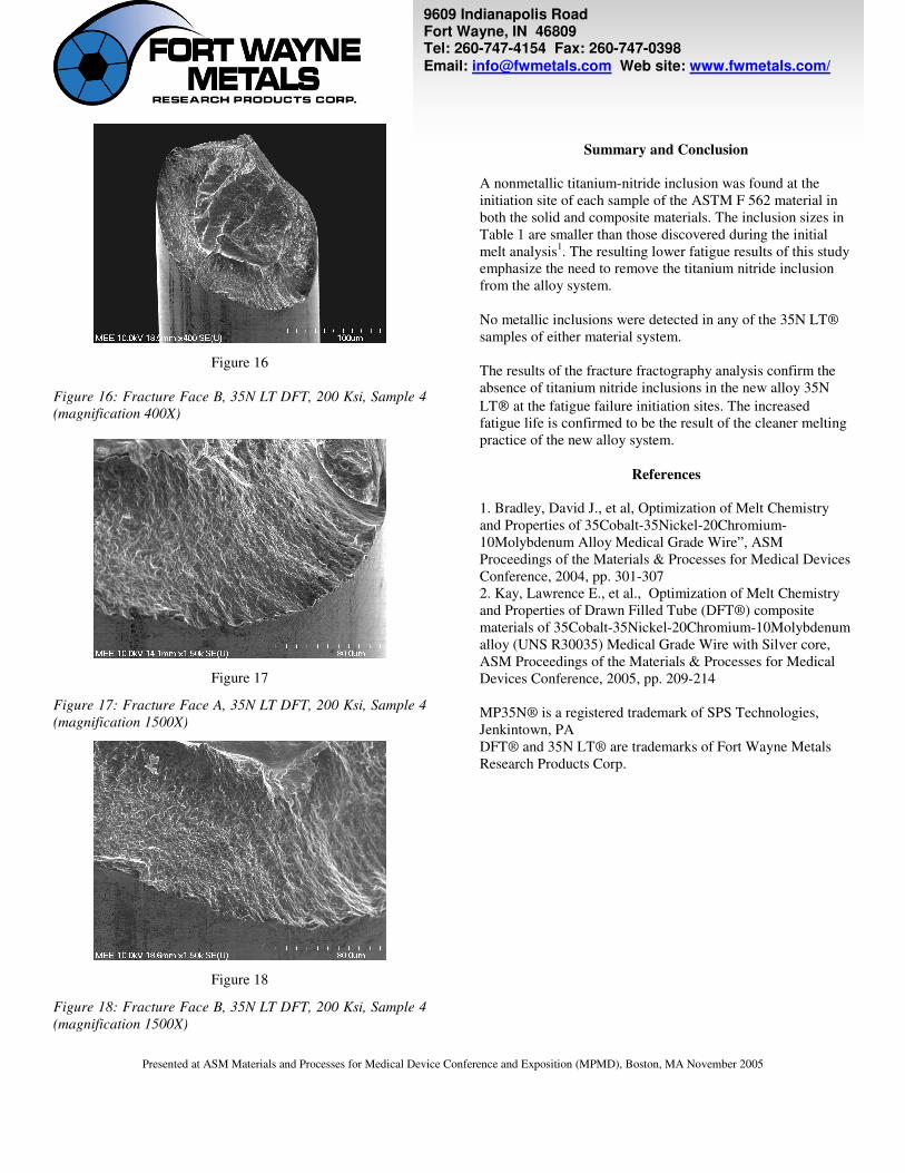
Figure 16
Figure 16: Fracture Face B, 35N LT DFT, 200 Ksi, Sample 4 (magnification 400X)
Figure 17
Figure 17: Fracture Face A, 35N LT DFT, 200 Ksi, Sample 4 (magnification 1500X)
Figure 18
Figure 18: Fracture Face B, 35N LT DFT, 200 Ksi, Sample 4 (magnification 1500X)
Summary and Conclusion
A nonmetallic titanium-nitride inclusion was found at the initiation site of each sample of the ASTM F 562 material in both the solid and composite materials. The inclusion sizes in Table 1 are smaller than those discovered during the initial melt analysis1. The resulting lower fatigue results of this study emphasize the need to remove the titanium nitride inclusion from the alloy system. No metallic inclusions were detected in any of the 35N LT® samples of either material system. The results of the fracture fractography analysis confirm the absence of titanium nitride inclusions in the new alloy 35N LT at the fatigue failure initiation sites. The increased fatigue life is confirmed to be the result of the cleaner melting practice of the new alloy system.
References 1. Bradley, David J., et al, Optimization of Melt Chemistry and Properties of 35Cobalt-35Nickel-20Chromium-10Molybdenum Alloy Medical Grade Wire”, ASM Proceedings of the Materials & Processes for Medical Devices Conference, 2004, pp. 301-307 2. Kay, Lawrence E., et al., Optimization of Melt Chemistry and Properties of Drawn Filled Tube (DFT®) composite materials of 35Cobalt-35Nickel-20Chromium-10Molybdenum alloy (UNS R30035) Medical Grade Wire with Silver core, ASM Proceedings of the Materials & Processes for Medical Devices Conference, 2005, pp. 209-214 MP35N® is a registered trademark of SPS Technologies, Jenkintown, PA DFT® and 35N LT® are trademarks of Fort Wayne Metals Research Products Corp.