Embed Size (px)
Citation preview
FBB SeriesHorizontal Boring and Milling MachineFBB-110 • 130
2
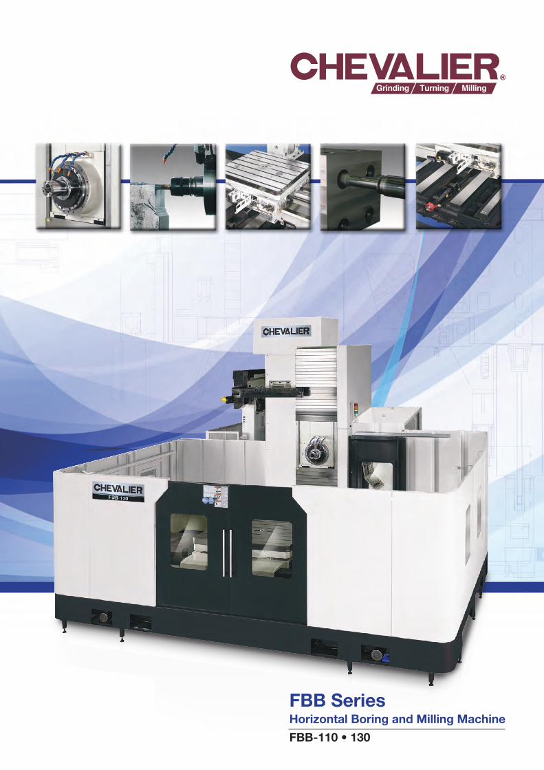
Wide Range of Machining Applications: With the heavy-duty, high precision design of this Series, the FBB-110 and 130 horizontal boring and milling machine with rotary table, offers more machining flexibility. Many FBB Series users in various industries, including the aerospace, automotive, energy, gas/oil, machining and job shop products fields, have experienced a dramatic increase in reliability and productivity. The series is designed for high performance, production batch machining of large work pieces for long cycle production with minimum non-cutting time.
Outstanding Structural Design: The series is perfect for your biggest projects. The extra rigid design of the main machine body and column ensure outstanding structural stability along with the one-piece machine base that includes four guide ways on the Z-axis for full table support.
The 26kW (35HP), 50-taper, large-diameter, cartridge-type, air-purged spindle runs with German made 2-speed gearbox that generates maximum 1,324NM (976 ft.-lbs.) at 188rpm to overcome most tough-material cutting conditions.
Spiral-type spindle cooling system provides constant, all-round lubrication, preventing thermal deformation and substantially prolonging the life of the spindle, bearings and gears. Combined with a gearbox, the spindle can be extended (W-axis) for deep-hole boring with high-rigidity and superior machining accuracy.
The series not only handles the big jobs but does it with cutting-edge control. The FANUC 0i-MD control comes with an AICC high-speed machining contour control, which has a smooth interpolation contouring control and an optional 200-block look-ahead function.
FBB Series Extra-Large, Extra-High Column Design Greatly Increases Boring and Milling Capability
FBB-110 • 130 SeriesTable Size: Up To 1,600mmL x 1,400mmW (63" x 55")Table Load: Up To 10,000kg (22,000 lbs.) X / Y / Z Travel: 2,000 x 1,800 x 1,500 (78.7" x 70.8" x 59")Spindle Speed With Gear Box: Up To 2,500rpm Spindle Motor: Up To 26kW (35HP)Spindle Taper: #50Bed Type With Full C-Axis Rotary Table W-Axis Includes: 110mm (4.3") Quill or 130mm (5.1") Quill
3
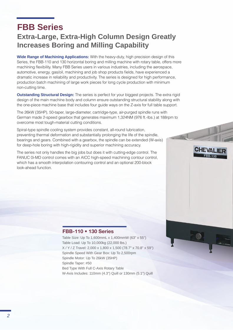
Note: The machine shown above includes optional semi-high splash guard and other options.
Table dimension: 1,400x1,600mm(55.1"x62.9")
48,930mm(L) x 6,024mm(W) x 5,000mm(H)352" x 237" x 197"
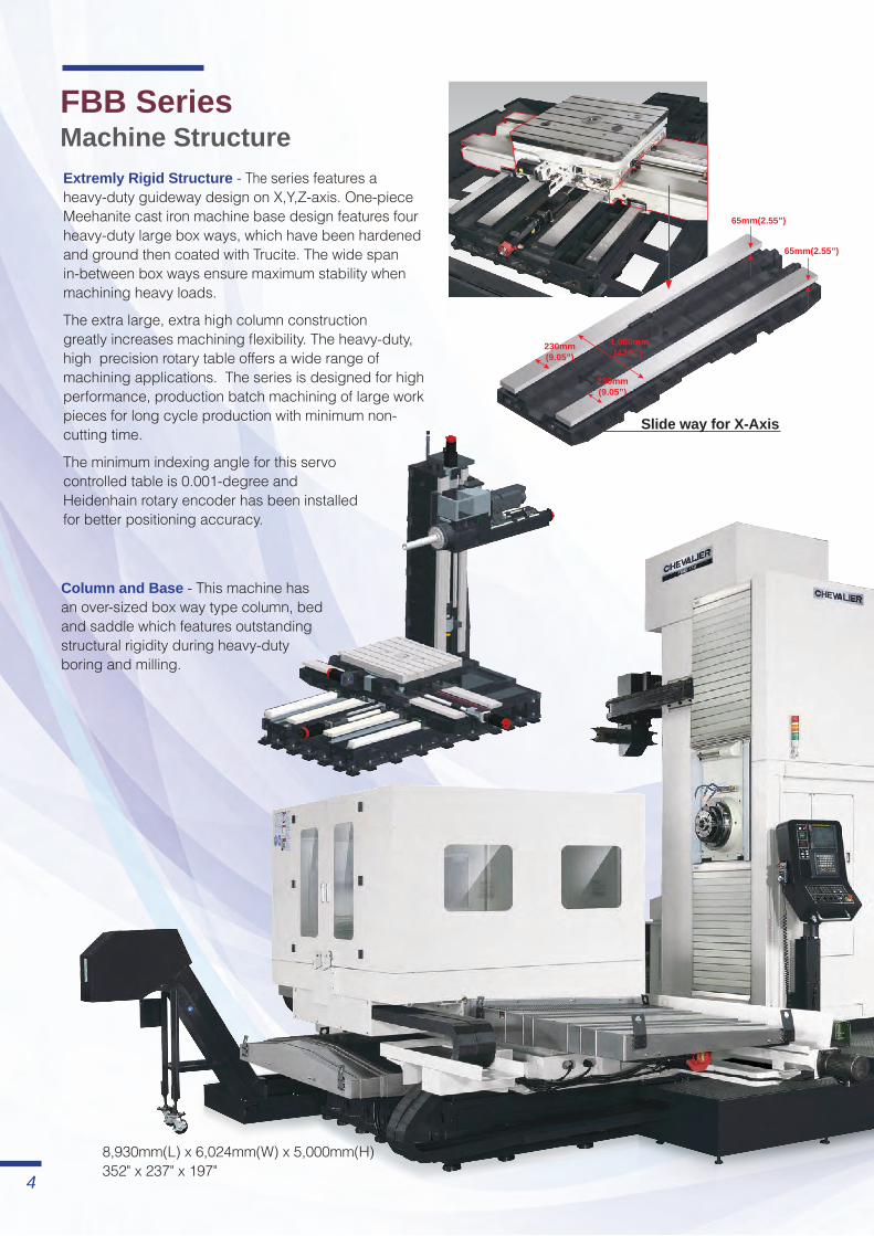
FBB Series Machine Structure
Column and Base - This machine has an over-sized box way type column, bed and saddle which features outstanding structural rigidity during heavy-duty boring and milling.
Extremly Rigid Structure - The series features a heavy-duty guideway design on X,Y,Z-axis. One-piece Meehanite cast iron machine base design features four heavy-duty large box ways, which have been hardened and ground then coated with Trucite. The wide span in-between box ways ensure maximum stability when machining heavy loads.
The extra large, extra high column construction greatly increases machining flexibility. The heavy-duty, high precision rotary table offers a wide range of machining applications. The series is designed for high performance, production batch machining of large work pieces for long cycle production with minimum non-cutting time.
The minimum indexing angle for this servo controlled table is 0.001-degree and Heidenhain rotary encoder has been installed for better positioning accuracy.
Slide way for X-Axis
230mm(9.05”)
230mm(9.05”)
1,080mm(42.5”)
65mm(2.55”)
65mm(2.55”)

Advanced High-Performance Spindle Design - Spiral type spindle cooling system provides constant, all around lubrication, preventing thermal deformation and substantially prolonging the life of the spindle, bearings and gears. Combined with a gear box, the spindle can be extended (W-axis) for deep hole boring with high rigidity and superior machining accuracy.
120mm
2,205mm
1,070mm19mm
200mm65mm
5
Rotary Table - Fully programmable rotary table with Heidenhain scale that indexes at a minimum 0.001̊, the combination of worm shaft and worm gear design ensures excellent machining accuracy. Using axial/radial bearings allows for heavy loading on the rotary table up to 10,000kg (22,000 lbs.).
To assure the rigidity of the table, the machine has a hydraulic break which locks the table in any position, plus a locking pin every 90̊.
Ball screws - Large Ø63mm (Ø2.4”) / Ø63mm (Ø2.4”) /Ø80mm (Ø3.1”) C3 Class ballscrew equipped on X / Y / X axes for precision and heavy-duty cutting operation. During assembling of the ballscrew, the laser unit is applied for calibration to ensure geometric accuracy.
Coolant System - The coolant nozzles positioned around the spindle features side cooling, which greatly increases the cooling effect for cutting tools and work-pieces. The process prevents a build-up on the edge of the tool and thermal deformation of the work-piece.The coolant through spindle feature shoots coolant directly to the cutting edge. This feature prolongs tool life, allows higher cutting speeds and flushes chips out during deep drilling.
6
5
2
4
3
3
1
1
7
2
3
4
5
6
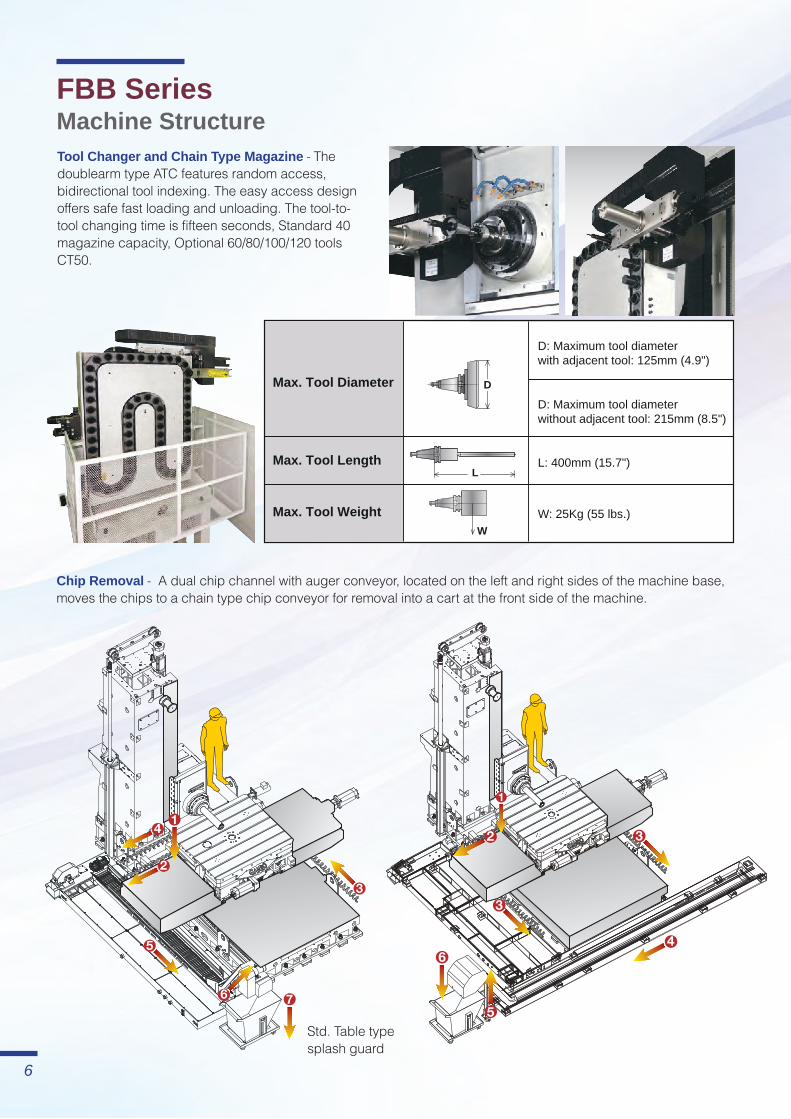
Std. Table type splash guard
6
Tool Changer and Chain Type Magazine - The doublearm type ATC features random access, bidirectional tool indexing. The easy access design offers safe fast loading and unloading. The tool-to-tool changing time is fifteen seconds, Standard 40 magazine capacity, Optional 60/80/100/120 tools CT50.
Chip Removal - A dual chip channel with auger conveyor, located on the left and right sides of the machine base, moves the chips to a chain type chip conveyor for removal into a cart at the front side of the machine.
FBB SeriesMachine Structure
D: Maximum tool diameterwith adjacent tool: 125mm (4.9")
D: Maximum tool diameterwithout adjacent tool: 215mm (8.5")
Max. Tool Diameter
Max. Tool Length
Max. Tool Weight
L
W
L: 400mm (15.7")
W: 25Kg (55 lbs.)
D
7
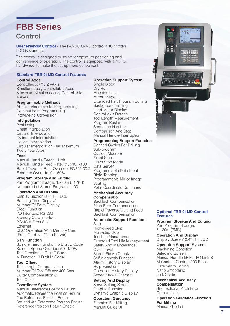
FBB Series Control User Friendly Control - The FANUC 0i-MD control's 10.4" color LCD is standard. The control is designed to swing for optimum positioning and convenience of operation. The control is equipped with a M.P.G. handwheel to make the set-up more convenient.
Standard FBB 0i-MD Control FeaturesControl Axes Controlled X / Y / Z –Axis Simultaneously Controllable Axes Maximum Simultaneously Controllable 4 AxesProgrammable Methods Absolute/Incremental Programming Decimal Point Programming Inch/Metric ConversionInterpolation Positioning Linear Interpolation Circular Interpolation Cylindrical Interpolation Helical Interpolation Circular Interpolation Plus Maximum Two Linear AxesFeed Manual Handle Feed: 1 Unit Manual Handle Feed Rate: x1, x10, x100 Rapid Traverse Rate Override: F0/25/100% Feedrate Override: 0~150%Program Storage And Editing Part Program Storage: 1,280m (512KB) Numbered of Stored Programs: 400Operation And Display Display Section 8.4” TFT LCD Running Time Display/ Number Of Parts Display Clock Function I/O Interface: RS-232 Memory Card Interface PCMCIA Front Slot Ethernet DNC Operation With Memory Card (Front Card Slot/Data Server)STN Function Spindle Feed Function: 5 Digit S Code Spindle Speed Override: 50~120% Tool Function: 4 Digit T Code M Function: 3 Digit M CodeTool Offset Tool Length Compensation Number Of Tool Offsets: 400 Sets Cutter Compensation C Tool OffsetCoordinate System Manual Reference Position Return Automatic Reference Position Return 2nd Reference Position Return 3rd and 4th Reference Position Return Reference Position Return Check
Operation Support System Single Block Dry Run Machine Lock Mirror Image Extended Part Program Editing Background Editing Load Meter Display Control Axis Detach Tool Length Measurement Program Restart Sequence Number Comparison And Stop Manual Handle InterruptionProgramming Support Function Canned Cycles For Drilling Sub-program Custom Macro B Exact Stop Exact Stop Mode Data Server Programmable Data Input Rigid Tapping Programmable Mirror Image Scaling Polar Coordinate CommandMechanical Accuracy Compensatio Backlash Compensation Pitch Error Compensation Rapid Traverse/Cutting Feed Backlash CompensationAutomatic Support Function Skip High-speed Skip Multi-step Skip Tool Life Management Extended Tool Life Management Safety And Maintenance Over Travel Stored Stroke Check 1 Self-diagnosis Function Alarm History Display Help Function Operation History Display Stored Stroke Check 2Setting And Display Servo Setting Screen Graphic Function Dynamic Graphic DisplayOperation Guidance Function For Milling Manual Guide 0i
Optional FBB 0i-MD Control FeaturesProgram Storage And Editing Part Program Storage: 5,120m (2MB)Operation And Display Display Screen10.4” TFT LCDOperation Support System Machining Condition Selecting Screen Manual Handle I/F For I/O Link B Al Contour Control: 200 Block Data Servo Editing Nano Smoothing Jerk ControlMechanical Accuracy Compensation Bi-directional Pitch Error CompensationOperation Guidance Function For Milling Manual Guide i
0
TORQUE(N-m) POWER(kW)
5
250020001500
10
15
500 1000
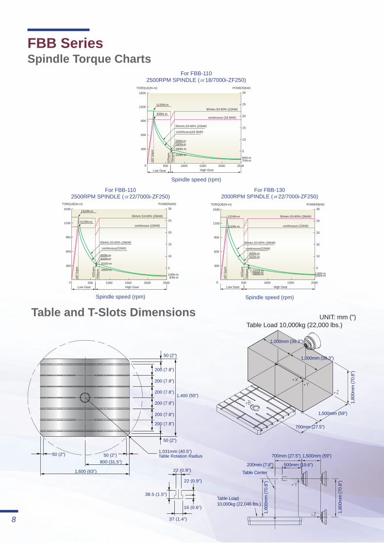
For FBB-1102500RPM SPINDLE (α18/7000i-ZF250)
Spindle speed (rpm)
20
25
30
600
1200
1500
187.
5rpm
625r
pm
936N-m
1120N-m
336N-m280N-m
84N-m70N-m
280N-m
234N-m
750r
pm
300
900
30mim,S3-60% (22kW)
continuous (18.5kW)
Low Gear High Gear
continuous(18.5kW)
30mim,S3-60% (22kW)
0
TORQUE(N-m) POWER(kW)
5
250020001500
10
15
500 1000
For FBB-1102500RPM SPINDLE (α22/7000i-ZF250)
Spindle speed (rpm)
20
25
30
600
1200
1500
187.
5rpm
625r
pm
1324N-m
1120N-m
400N-m332N-m
100N-m83N-m
280N-m
750r
pm
300
900
331N-m
Low Gear High Gear
continuous(22kW)
30mim,S3-60% (26kW)
30mim,S3-60% (26kW)
continuous (22kW)
0
TORQUE(N-m) POWER(kW)
5
20001500
10
15
500 1000
Spindle speed (rpm)
20
25
30
600
1200
1500
126N-m105N-m
300
900
For FBB-1302000RPM SPINDLE (α22/7000i-ZF250)
187.
5rpm
625r
pm
1324N-m
1120N-m
400N-m332N-m
331N-m280N-m
750r
pm
Low Gear High Gear
continuous(22kW)
30mim,S3-60% (26kW)
30mim,S3-60% (26kW)
continuous (22kW)
1,600 (63”)
800 (31.5”)50 (2”)
50 (2”)
200 (7.8”)
200 (7.8”)
200 (7.8”)
200 (7.8”)
200 (7.8”)
1,400 (55”)
37 (1.4”)
38.5 (1.5”)
22 (0.9”)
16 (0.6”)
22 (0.9”)
1,031mm (40.5”) Table Rotation Radius
50 (2”)
50 (2”)
200 (7.8”)
1,600 (63”)
800 (31.5”)50 (2”)
50 (2”)
200 (7.8”)
200 (7.8”)
200 (7.8”)
200 (7.8”)
200 (7.8”)
1,400 (55”)
37 (1.4”)
38.5 (1.5”)
22 (0.9”)
16 (0.6”)
22 (0.9”)
1,031mm (40.5”) Table Rotation Radius
50 (2”)
50 (2”)
200 (7.8”)
1,000mm (39.3”)
1,000mm (39.3”)
700mm (27.5”)
1,500mm (59”)
1,80
0mm
(70.
8”)
1,80
0mm
(70.
8”)
1,80
0mm
(70.
8”)
Table Center
Table Load10,000kg (22,046 lbs.)
500mm (19.6”)
700mm (27.5”) 1,500mm (59”)
200mm (7.8”)
8
UNIT: mm (")Table Load 10,000kg (22,000 lbs.)
Table and T-Slots Dimensions
FBB SeriesSpindle Torque Charts

Oil chillerHydraulic
tank
(The max.stroke for opening the door)
3,30
0 (T
he h
eigh
t of t
ool c
hang
e)
7,840 (for spindle quill: Ø110mm)8,320 (for spindle quill: Ø130mm)
7,84
0 (fo
r spi
ndle
qui
ll: Ø
110m
m)
8,32
0 (fo
r spi
ndle
qui
ll: Ø
130m
m)
7,02
5
1,75
0
5,83
02,
255
2,90
0
5,00
0
2,25
0
565
7771,800
5,840 4,060
4,2201,990
1,495
Oil chiller
The port of power supply
The port of air supplyHydraulic
tank
8,45
0(fo
r spi
ndle
qui
ll: Ø
110m
m)
8,93
0(fo
r spi
ndle
qui
ll: Ø
130m
m)
3,42
15,
000
2,54
5 1,10
0
1,75
0
3,30
01,
445
1,600
1,0001,0002,785 2,785
1,880
3,1702,854
2,300
1,88
0
1,40
0
9
Spindle quill: Ø110/130mm(Optional semi-high guard type dimensional drawings)
Spindle quill: Ø110/130mm(Standard table splash guard type dimensional drawings)
FBB SeriesDimensional Drawings
Ø23 (0.9”)
45 (1
.7”)
101.
8 (4
”)38
(1.4
”)
Ø100 (3.9”)
Ø80 (3”)
7.84 (0.3”)
15 (0.59”)
3 (0.11”)23.2 (0.91”)Ø25 (0.98”)
Ø69.85 (2.75”)
90 (3
.5”) 45
(1.7
7”) 8 (0.31”)
7 (0.27”)
35 (1
.3”)
5 (0.19”)
Ø17 (0.66”)
45°
30°
60°
Taper 7/24
M24x3P
Ø23 (0.9”)
45°
30°
60°
Taper 7/24
1” - 8 INC
5 (0.19”)
45 (1
.77”
)
35 (1
.37”
)
7 (0.27”)
45.8
(1.8
”)69
.5 (2
.7”)
101.
6 (4
”)19
.05
(0.7
5”)
Ø98.43 (3.87”)Ø91.29 (3.59”)Ø25.9 (1.01”)
Ø69.85 (2.75”) 3.174 (0.12”)
7.956 (0.31”)
3.835 (0.15”)
10
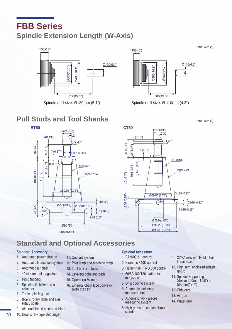
11. Coolant system12. Pilot lamp and machine lamp13. Tool box and tools14. Leveling bolts and pads15. Operation Manual16. External chain type conveyor
(with out cart)
9. X/Y/Z-axis with Heidenhain linear scale
10. High semi enclosed splash guard
11. Spindel Supporting Sleeve 300mm(11.8”) or 500mm(19.7”)
12. Chip cart13. Air gun14. Water gun
Optional Accessory1. FANUC 31i control2. Siemens 840D control3. Heidenhain iTNC 530 control4. 60/80/100/120 station tool
magazine5. Chip cooling system6. Automatic tool length
measurement7. Automatic work pieces
measuring system8. High pressure coolant through
spindle
Standard Accessory1. Automatic power shut off2. Automatic lubrication system3. Automatic air blast4. 40 station tool magazine5. Rigid tapping6. Spindle oil chiller and oil
skimmer7. Table splash guard8. B-axis rotary table and axis
rotary scale9. Air conditioned electric cabinet10. Dual screw type chip auger
Spindle quill size: Ø 110mm (4.3”)Spindle quill size: Ø130mm (5.1”)
Pull Studs and Tool Shanks
UNIT: mm (")
UNIT: mm (")
CT50BT50
FBB SeriesSpindle Extension Length (W-Axis)
Standard and Optional Accessories
11
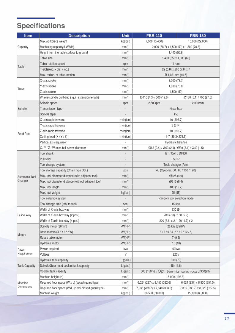
SpecificationsItem Description Unit FBB-110 FBB-130
Capacity
Max.workpiece weight kg(lbs.) 7,000(15,400) 10,000 (22,000)
Machining capacity(LxWxH) mm(") 2,000 (78.7) x 1,500 (59) x 1,800 (70.8)
Height from the table surface to ground mm(") 1,445 (56.8)
Table
Table size mm(") 1,400 (55) x 1,600 (63)
Table rotation speed rpm 1 rpm
T-slots(wid. x dis. x no.) mm(") 22 (0.8) x 200 (7.8) x 7
Max. radius. of table rotation mm(") R 1,031mm (40.5)
Travel
X-axis stroke mm(") 2,000 (78.7)
Y-axis stroke mm(") 1,800 (70.8)
Z-axis stroke mm(") 1,500 (59)
W-axis(spindle quill dia. & quill extension length) mm(") Ø110 (4.3) / 500 (19.6) Ø130 (5.1) / 700 (27.5)
Spindle
Spindle speed rpm 2,500rpm 2,000rpm
Transmission type - Gear box
Spindle taper - #50
Feed Rate
X-axis rapid traverse m/in(ipm) 10 (393.7)
Y-axis rapid traverse m/in(ipm) 8 (314)
Z-axis rapid traverse m/in(ipm) 10 (393.7)
Cutting feed (X / Y / Z) m/in(ipm) 1-7 (39.3~275.5)
Vertical axis equalizer - Hydraulic balance
X / Y / Z / W axes ball screw diameter mm(") Ø63 (2.4) / Ø63 (2.4) / Ø80 (3.1) / Ø40 (1.5)
Automatic Tool Changer
Tool shank - BT / CAT / DIN50
Pull stud - P50T-1
Tool change system - Tools changer (Arm)
Tool storage capacity (Chain type Opt.) pcs 40 (Optional: 60 / 80 / 100 / 120)
Max. tool diameter distance (with adjacent tool) mm(") Ø125 (4.9)
Max. tool diameter distance (without adjacent tool) mm(") Ø215 (8.4)
Max. tool length mm(") 400 (15.7)
Max. tool weight kg(lbs.) 25 (55)
Tool selection system - Random tool selection mode
Tool change time (tool-to-tool) sec. 15 sec.
Guide Way
Width of X-axis box way mm(") 230 (9)
Width of Y-axis box way (2 pcs.) mm(") 200 (7.8) / 150 (5.9)
Width of Z-axis box way (4 pcs.) mm(") 200 (7.8) x 2 / 120 (4.7) x 2
Motors
Spindle motor (30min) kW(HP) 26 kW (35HP)
Drive motors (X / Y / Z / W) kW(HP) 6 / 7 / 9 / 4 (7.5 / 9 / 12 / 5)
Rotary table motor kW(HP) 7 (9.5)
Hydraulic motor kW(HP) 7.5 (10)
Power Requirement
Power required kva 60kva
Voltage V 220V
Tank Capacity
Hydraulic tank capacity L (gals.) 300 (79)
Spindle/Gear head coolant tank capacity L(gals.) 45 (11.8)
Coolant tank capacity L(gals.) 600 (158.5) / Opt. Semi-high splash guard 900(237)
Machine Dimensions
Machine height (H) mm(") 5,000 (196.8)
Required floor space (W x L) (splash guard type) mm(") 6,024 (237) x 8,450 (332.6) 6,024 (237) x 8,930 (351.5)
Required floor space (WxL) (semi-closed guard type) mm(") 7,335 (288.7) x 7,840 (308.6) 7,335 (288.7) x 8,320 (327.5)
Machine weight kg(lbs.) 26,500 (58,300) 29,000 (63,800)
CAT
:QB
16-1
6001
C00
/ 20
1401
/ 10
00 P
1Al
l Rig
hts
Res
erve
d.©
1978
-201
4
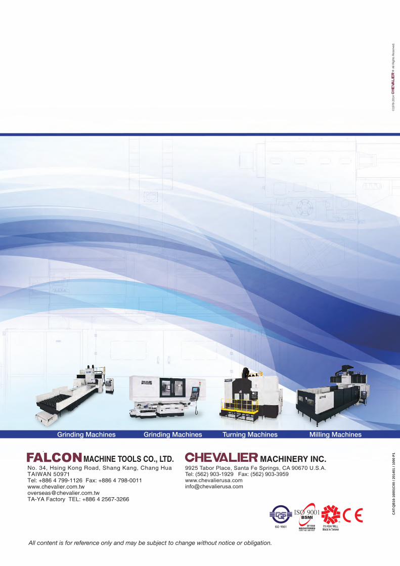
All content is for reference only and may be subject to change without notice or obligation.
Grinding Machines Grinding Machines Turning Machines Milling Machines
OUTLINEDTYPE
NOTOUTLINEDTYPE
OUTLINEDTYPE
50971 彰化縣伸港鄉興工路34號電話: +886 4 799-1126(代表號)傳真: +886 4 798-0011http:// www.chevalier.com.twE-mail: [email protected]
福裕事業股份有限公司總公司
蘇州偉揚精機有限公司中國營運總部
常熟市東南高新技術開發區黃浦江路58號電話: +86 512 82355999(代表號)傳真: +86 512 82355966 郵編:215500 http:// www.szchevalier.comE-mail: [email protected]
9925 Tabor Place, Santa Fe Springs, CA 90670 U.S.A.Tel: (562) 903-1929 Fax: (562) 903-3959http:// www.chevalierusa.comE-mail: [email protected]
U.S.A. Headquarters
MACHINERY INC.