Embed Size (px)
Citation preview

FD1X3
Servo driver user menu


Version modification instruction
Date Modification content
2017-08-14 In chapter 9 and 10, 485 and 232 communication example are added.
2017-08-17 In chapter 11, SDO example is added.
2017-12-12 Modify part of text problem
2017-12-28 In chapter 11, description of RPDO is modified,
2018-03-09 Description of terminal resistor (SW8) in FD123 and FD133 is added.
2018-04-25 SMS absolute motor is added.

Preface Product Acceptance
Thank you for using Kinco Servo product!
The accessories of Kinco every series & different types drivers are different. We advice you
accept products before use.
Item forAcceptance RemarkWhether the model of a delivered FD series
servo system is consistent with the specified model
Check the nameplate of a servo motor and that of a servo
driver
Whether the accessories included in the packing list
are complete
Check the packing list
Whether any breakage occurs Check the external appearance completely for any losses
that are caused by transportation
Whether any screws are loose Check for loose screws with a screwdriver
Whether the motor wiring is correct Purchase motor accessory packages if no wiring are
purchased
Table Product Acceptance

CatalogPREFACE PRODUCT ACCEPTANCE.....................................................................................................................................1
CHAPTER 1 SYSTEM CONFIGURATION AND TYPES...........................................................................................................6
1.1 PRODUCT TYPE DESCRIPTION..........................................................................................................................................6
1.1.1 Model description of Servo Motors................................................................................................................ 6
1.1.2 Driver description............................................................................................................................................7
1.1.3 Cable............................................................................................................................................................... 7
CHAPTER 2 SYSTEM INSTALLMENT REQUIREMENTS AND PRECAUTIONS.......................................................................9
2.1 DRIVER MOUNTING......................................................................................................................................................9
2.1.1 Mounting........................................................................................................................................................ 9
2.2 APPLICATION REQUIREMENTS OF DRIVER........................................................................................................................10
2.2.1 Transportation and saving conditions.......................................................................................................... 10
2.2.2 Technology requirements............................................................................................................................. 11
2.2.3 Operator’s requirements.............................................................................................................................. 11
2.2.4 Environment requirements........................................................................................................................... 11
2.2.5 Precautions................................................................................................................................................... 12
2.3 SERVO MOTOR WIRE DIAGRAM.....................................................................................................................................13
2.3.1 SMC60S-0020-30AAK-(60flange,200W,without brake,incremental encoder)...............................13
2.3.2 SMC60S-0020-30ABK-(60 flange,200W,with brake,incremental encoder)................................... 14
2.3.3 SMC60S-0020-30MAK-(60 flange,200W,without brake,magnetoelectric encoder)......................14
2.3.4 SMS60S-0020-30KAK-(60 flange,200W,without brake,absolute encoder)....................................15
2.3.5 SMS60S-0020-30KBK-(60 flange,200W,with brake,absolute encoder)......................................... 15
2.3.6 SMC60S-0040-30AAK-(60 flange,400W,without brake,incremental encoder)..............................16
2.3.7 SMC60S-0040-30ABK-(60 flange,400W,with brake,incremental encoder)................................... 16
2.3.8 SMC60S-0040-30MAK-(60 flange,400W,without brake,magnetoelectric encoder)......................17
2.3.9 SMS60S-0040-30KAK-(60 flange,400W,without brake,absolute encoder)....................................17
2.3.10 SMS60S-0040-30KBK-(60 flange,400W,with brake,absolute encoder)....................................... 18
2.3.11 SMC80S-0040-30AAK-(80 flange,400W,without brake,incremental encoder)............................18
2.3.12 SMC80S-0040-30ABK-(80 flange,400W,with brake,incremental encoder)................................. 19
2.3.13 SMC80S-0040-30MAK-(80 flange,400W,without brake,magnetoelectric encoder)....................19
2.3.14 SMS80S-0040-30KAK-(80 flange,400W,without brake,absolute encoder)..................................20
2.3.15 SMS80S-0040-30KBK-(80 flange,400W,with brake,absolute encoder)....................................... 20
2.3.16 SMC80S-0075-30AAK-(80 flange,750W,without brake,absolute encoder)................................. 21
2.3.17 SMC80S-0075-30ABK-(80 flange,750W,with brake,incremental encoder)................................. 21
2.3.18 SMC80S-0075-30MAK-(80 flange,750W,without brake,magnetoelectric encoder)....................22
2.3.19 SMS80S-0075-30KAK-(80 flange,750W,without brake,absolute encoder)..................................22
2.3.20 SMS80S-0075-30KBK-(80 flange,750W,with brake,absolute encoder)....................................... 23
2.4 SERVO MOTOR TORQUE CURVE.....................................................................................................................................23
2.4.1 200W servo motor torque curve...................................................................................................................23
2.4.2 400W servo motor torque curve...................................................................................................................24
2.4.3 750W servo motor torque curve...................................................................................................................24
2.5 SERVO MOTOR INSTALLATION.......................................................................................................................................24
2.5.1 Installation requirement...............................................................................................................................24
2.5.2 Environment conditions................................................................................................................................25
2.5.3 Precautions................................................................................................................................................... 25
CHAPTER 3 INTERFACE AND WIRING..............................................................................................................................27
3.1 COMPONENTS NAME..................................................................................................................................................27
3.1.1 FD123............................................................................................................................................................27
3.1.2 FD133 driver................................................................................................................................................. 28
3.2 EXTERNAL WIRING..................................................................................................................................................... 29
3.2.1 FD123 External wiring diagram....................................................................................................................29
3.2.2 FD133 External wiring diagram....................................................................................................................30
3.3 BUS COMMUNICATION PORT(X1)........................................................................................................................... 31
3.4 RS232 PORT(X2)................................................................................................................................................31
3.5 EXTERNAL INPUT&OUTPUT(X3)..............................................................................................................................32
3.6 ENCODER INPUT(X4)............................................................................................................................................34
3.7 MOTOR/POWER (X5)..........................................................................................................................................35
3.7.1 FD123 X5 pin definition................................................................................................................................ 35
3.7.2 FD133 X5 pin definition................................................................................................................................ 35
CHAPTER 4 KINCOSERVO SOFTWARE INTRODUCTION..................................................................................................36
4.1 FAST START...............................................................................................................................................................36
4.1.1 Language configuration................................................................................................................................36
4.1.2 Opening and saving project files.................................................................................................................. 36
4.1.3 Start communication.................................................................................................................................... 37
4.1.4 Node ID and baud rate................................................................................................................................. 37
4.1.5 Object (add,delete,help)......................................................................................................................... 37
4.2 INITIALIZE, SAVE AND REBOOT......................................................................................................................................38
4.3 FIRMWARE UPDATE....................................................................................................................................................38
4.4 READ/WRITE CONTROLLER CONFIGURATION....................................................................................................................39
4.4.1 Read setting from controller.........................................................................................................................39
4.4.2 Write settings to controller...........................................................................................................................40
4.5 DIGITAL IO FUNCTIONS...............................................................................................................................................41
4.5.1 Digital input.................................................................................................................................................. 42
4.5.2 Digital output................................................................................................................................................43
4.6 SCOPE..................................................................................................................................................................... 44
4.7 ERROR DISPLAY AND ERROR HISTORY.............................................................................................................................45
CHAPTER 5 OPERATION MODE.......................................................................................................................................48
5.1 VELOCITY MODE (-3, 3)..............................................................................................................................................48
5.1.1 Analog speed mode...................................................................................................................................... 49
5.1.2 DIN Speed mode........................................................................................................................................... 51
5.2 TORQUE MODE (4).................................................................................................................................................... 53
5.2.1 Analog torque mode.....................................................................................................................................53
5.3 POSITION MODE (1).................................................................................................................................................. 55
5.4 PULSE MODE (-4)......................................................................................................................................................56
5.5 HOMING MODE (6)................................................................................................................................................57
CHAPTER 6 TUNING OF THE SERVO SYSTEM CONTROL..................................................................................................67
6.1 TUNING OF VELOCITY LOOP..........................................................................................................................................67
6.2 TUNING OF POSITION LOOP......................................................................................................................................... 70
6.3 FACTORS WHICH INFLUENCE TUNING RESULTS................................................................................................................. 72
CHAPTER 7 ALARMS AND TROUBLESHOOTING.............................................................................................................76
CHAPTER 8 LIST OF MOTOR CONTROLLER PARAMETERS.............................................................................................. 82
8.1 MODE AND CONTROL(0X6040).............................................................................................................................82
8.2 DATA MEASURING......................................................................................................................................................84
8.3 TARGET OBJECT(0X607A).....................................................................................................................................84
8.4 DIN SPEED/POSITION(0X2020)..............................................................................................................................85
8.5 PERFORMANCE OBJECTS(0X6065)..........................................................................................................................86
8.6 HOME CONTROL(0X6098)....................................................................................................................................88
8.7 VELOCITY LOOP(0X60F9)......................................................................................................................................88
8.8 POSITION LOOP(0X60FB)..................................................................................................................................... 89
8.9 INPUT & OUTPUT(0X2010)..................................................................................................................................89
8.10 PULSE INPUT(0X2508).......................................................................................................................................92

8.11 SAVE(0X2FF0)..................................................................................................................................................93
8.12 ERROR CODE(0X2601).......................................................................................................................................93
8.13 STOP..................................................................................................................................................................... 94
CHAPTER 9 RS232............................................................................................................................................................96
9.1 RS232 WIRING DEFINITION.........................................................................................................................................96
9.1.1 Pin definition.................................................................................................................................................97
9.1.2 Multi-point connection................................................................................................................................. 97
9.2 TRANSPORT PROTOCOL............................................................................................................................................... 98
9.2.1 Point-to-point protocol................................................................................................................................. 98
9.2.2 Multi-point protocol......................................................................................................................................99
9.3 DATA PROTOCOL........................................................................................................................................................99
9.3.1 Download (from host to slave)................................................................................................................... 100
9.3.2 Upload (from slave to host)........................................................................................................................101
9.4 RS232 TELEGRAM EXAMPLE......................................................................................................................................101
CHAPTER 10 RS485 COMMUNICATION........................................................................................................................104
10.1 RS485 WIRING.....................................................................................................................................................104
10.2 RS485 COMMUNICATION PARAMETERS.....................................................................................................................104
10.3 MODBUS RTU................................................................................................................................................... 105
10.4 FUNCTION CODE OF MODBUS................................................................................................................................. 105
10.5 MODBUS MESSAGE EXAMPLE.................................................................................................................................. 106
CHAPTER 11 CANOPEN................................................................................................................................................. 109
11.1 CANOPEN COMMUNICATION PROTOCOL....................................................................................................................109
11.2 HARDWARE INTRODUCTION.....................................................................................................................................110
11.3 SOFTWARE INTRODUCTION...................................................................................................................................... 111
11.3.1 EDS introduction....................................................................................................................................... 111
11.3.2 SDO introduction...................................................................................................................................... 112
11.3.3 PDO introduction...................................................................................................................................... 113
11.4 CANOPEN COMMUNICATION EXAMPLE..................................................................................................................... 118
11.4.1 Connect to KincoServo+............................................................................................................................ 118
11.4.2 Configure CANopen parameters...............................................................................................................119
11.4.3 PDO transmission mode configuration.....................................................................................................122
11.4.4 CANopen send message example.............................................................................................................127
NMT management message............................................................................................................................... 128

APPENDIX 1 CONFIGURE THIRD-PARTY MOTORS........................................................................................................134
APPENDIX 2 FORMULA.................................................................................................................................................136
APPENDIX 3 USE OF BRAKE RESISTOR..........................................................................................................................138
APPENDIX 4 GENERAL LOAD INERTIA CALCULATION..................................................................................................139

Chapter 1 System configuration and types
1.1 Product type description
1.1.1 Model description of Servo Motors

1.1.2 Driver description
1.1.3 Cable


Chapter 2 System installment requirements and precautions
2.1 Driver mounting
2.1.1 Mounting
Figure 2–1 FD123 driver size Figure 2–2 FD133 driver size
Precaution
Around driver, connection space need to be reserved, >60mm.

Warning
Please carefully read and follow requirements of this menu. It can help you to
correctly set up and operate driver, and make driver in the best performance
Please install it indoor of no rain and direct sunlight.
This product conform with EMC's standard 2014/30/EU and low-voltage
standard 2014/35/EU(LVD)
Occasion (without Grinding fluid, Oil mist, Iron powder, cutting and etc)
Occasion (good ventilation, no Moisture, oil and water, no heat source such as
stove)
Occasion without shock
Please do not use gasoline, thinner, Acid & Alkaline detergent, in order to avoid
discoloration or damage
2.2 Application requirements of driver
Please ensure this menu can be provided for design engineer, operators and staffs (or
machine) who is responsible to adjust and use this product
Please ensure to follow requirements of this file all the time. And consider other accessory and
module's file
Please consider destination's law, and:
—regulations and standards
—test organization and insurance company's regulation
—national specifications
2.2.1 Transportation and saving conditions
Please ensure product do not overburn during the process of transportation and saving,
including:
—Mechanical load
—non-allowed temperature
—Water
—Corrosive gas
Please use original package to save and transport. Original package provide efficient
protection so as to avoid influence of general issues
2.2.2 Technology requirements
Must follow:
Specified connection and environment condition in product technology data and all of other
connecting accessory's technology requirements. As long as product specification
requirements are conformed, users are allowed to operate according to related safety
regulations.
Please follow instructions and alerts in this product
2.2.3 Operator’s requirements
This product must be operated by electrical engineers who are familiar with instructions
below:
—Electrical control system's installation and operation
—Regulations of operating safety project system
—Regulations of accident protection and occupation safety
—Product using menu
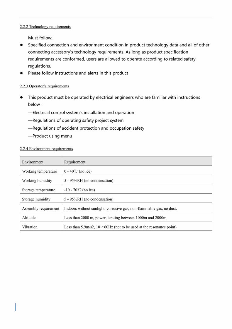
2.2.4 Environment requirements
Environment Requirement
Working temperature 0 - 40℃ (no ice)
Working humidity 5 - 95%RH (no condensation)
Storage temperature -10 - 70℃ (no ice)
Storage humidity 5 - 95%RH (no condensation)
Assembly requirement Indoors without sunlight, corrosive gas, non-flammable gas, no dust.
Altitude Less than 2000 m, power derating between 1000m and 2000m
Vibration Less than 5.9m/s2, 10〜60Hz (not to be used at the resonance point)

2.2.5 Precautions
Alarm
Please follow menu's all required operation. And refer to figure 2-3 to correctly
install servo system.
In the case of use of an external brake resistor, provide adequate space around
the brake resistor since it can become very hot.
The installation orientation is vertical to provide sufficient convection air flow
through the controller housing.
Figure 2–3 Install orientation, distances and clearances

Note
Tightly fasten the screws that fix the motor;
Make sure to tightly fasten all fixed points when fixing the driver;
Driver & motor power cable, brake cable and encoder cannot be over
stretching;
Use a coupling shaft or expansion sleeve to ensure that both the motor shaft
and equipment shaft are properly centered;
Avoid anything strange into driver. When Screw, metals shavings and other
things with conductivity or flammability enter into driver, it might causes
fire or electric shock. For safety, do not use any damaged servo driver or any
driver with damaged parts;
2.3 Servo motor wire diagram
2.3.1 SMC60S-0020-30AAK-(60flange,200W,without brake,incremental encoder)

2.3.2 SMC60S-0020-30ABK-(60 flange,200W,with brake,incremental encoder)
2.3.3 SMC60S-0020-30MAK-(60 flange,200W,without brake,magnetoelectric encoder)

2.3.4 SMS60S-0020-30KAK-(60 flange,200W,without brake,absolute encoder)
2.3.5 SMS60S-0020-30KBK-(60 flange,200W,with brake,absolute encoder)
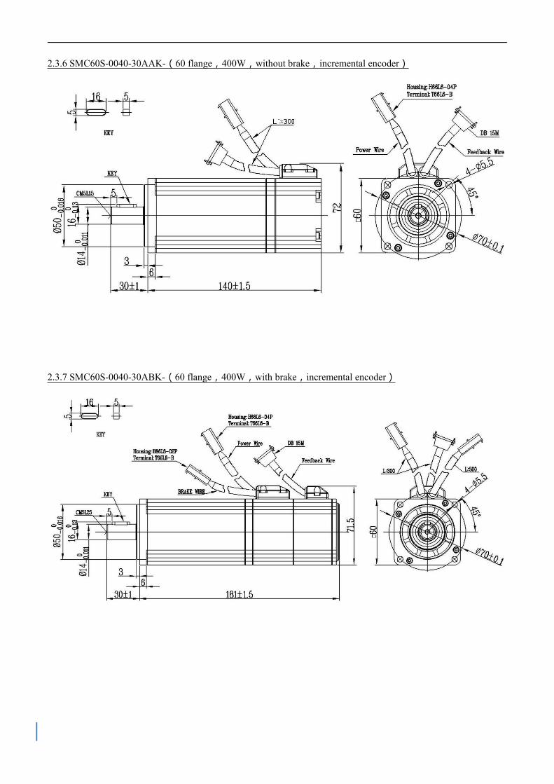
2.3.6 SMC60S-0040-30AAK-(60 flange,400W,without brake,incremental encoder)
2.3.7 SMC60S-0040-30ABK-(60 flange,400W,with brake,incremental encoder)

2.3.8 SMC60S-0040-30MAK-(60 flange,400W,without brake,magnetoelectric encoder)
2.3.9 SMS60S-0040-30KAK-(60 flange,400W,without brake,absolute encoder)

2.3.10 SMS60S-0040-30KBK-(60 flange,400W,with brake,absolute encoder)
2.3.11 SMC80S-0040-30AAK-(80 flange,400W,without brake,incremental encoder)

2.3.12 SMC80S-0040-30ABK-(80 flange,400W,with brake,incremental encoder)
2.3.13 SMC80S-0040-30MAK-(80 flange,400W,without brake,magnetoelectric encoder)

2.3.14 SMS80S-0040-30KAK-(80 flange,400W,without brake,absolute encoder)
2.3.15 SMS80S-0040-30KBK-(80 flange,400W,with brake,absolute encoder)

2.3.16 SMC80S-0075-30AAK-(80 flange,750W,without brake,absolute encoder)
2.3.17 SMC80S-0075-30ABK-(80 flange,750W,with brake,incremental encoder)

2.3.18 SMC80S-0075-30MAK-(80 flange,750W,without brake,magnetoelectric encoder)
2.3.19 SMS80S-0075-30KAK-(80 flange,750W,without brake,absolute encoder)

2.3.20 SMS80S-0075-30KBK-(80 flange,750W,with brake,absolute encoder)
2.4 Servo motor torque curve
2.4.1 200W servo motor torque curve

2.4.2 400W servo motor torque curve
2.4.3 750W servo motor torque curve
2.5 Servo motor installation
2.5.1 Installation requirement
Alarm
Please install it indoor of no rain and direct sunlight.
Please do not use this product in the corrosive environment (Hydrogen sulfide,
Sulfurous acid, Chlorine, Ammonia, Sulfur, Chlorinated gas, Acid, Alkaline, Salt,
etc), flammable gas, combustible and etc.
Occasion (without Grinding fluid, Oil mist, Iron powder, cutting and etc).
Occasion (good ventilation, no Moisture, oil and water, no heat source such as
stove).
Occasion which is easy to be checked and cleaned.
Occasion without shock.
Please do not use motor in the closed environment.
For installation spacing, please follow the requirements of this manual. Using

life of motors depend on level of working environment.
2.5.2 Environment conditions
Environment Conditions
Working
temperature0℃~40℃(no ice)
Working
humidity5~95%RH(no condensation)
Storage
temperature-10℃~70℃(no ice)
Storage
temperature5~95%RH(no condensation)
vibration Running, less than 49m/s2(5G)、stopping, less than 24.5m/s2(2.5G)
collision Less than 98m/s²(10G)
Protection level IP65(Except for shaft hollow part,part of motor connector connect terminal )
Altitude Less than 1000m
2.5.3 Precautions
Item Description
Stain
proofingPlease wipe anti-rust agent on the motor's shaft and then make some anti-rust treatments.
Installation
method
Improper installation method will cause damage of motor's encoder. Please note the following
during the installation process:
● When operators installation pulleys on the servo motor shaft with key, it is necessary to use
screw hole. In order to install pulleys, operators need to insert double-headed nail into screw
holes and use washers on the surface of coupled end. Then use nuts to fix into pulleys gradually.
● For servo motor shaft with keys, Operator need to use screw hole on the shaft to install. For
motors shaft with no key, operators need to use friction coupling or other analogous methods.
● When operators need to disassemble pulleys, operators need to use pulley remover so as to
make shaft avoid strong impact of load.
● In order to make it more safe, it is necessary to install protection cover or some analogous
equipment in rotation area. For example, pulleys installed on the shaft.

Centering
●When it is connected with machine, please use coupling and make shaft center of servo motor
and machine stay in a line. When operators install servo motors, please achieve requirements of
centering accuracy. If centering is not accurate, there will be shock and sometimes it will make
bearings and encoders.
Installation
direction● Servo motors can be installed in vertical or horizontal direction.
Oil & water
solution
When it is used in the occasion with drops, please use after make sure protection level of servo.
When oil will drop into shaft penetrating part (beside shaft penetrating part, please choose servo
motors with oil seal. The using condition of servo motors with oil seal:
● Make sure the oil level is lower than month of oil seal.
● Please use when oil seal make sure that oil splash degree is good.
● When servo motors are installed in vertical upward direction, please avoid oil accumulating in
the month of oil seal.
Cable Please do not make cable bending or pull the cable. When using it, please do not make it too tight.
Connector
In terms of connectors, please note the following:
● When connectors are connected. please make sure there is no foreign body such as trash or
mental slices.
● When connectors are connected into servo motors, please connect to one side of servo motor's
main circuit cable and make sure ground cable of main cable connecting stably. If operators first
connect one side of encoder cable, then, encoder may have some faults because of voltage
difference between PEs.
● During the process of wiring, please make sure pin arrangement is correct.
● Connector is made of resin. Please do not add pressure to avoid damage of connectors.
● When handling operations is done (cables are connected), please hold main body of servo
motors. If operators just hold cable to handle, it may cause connectors damage or make cable cut
off.
● If operators use bend cable, please do not add pressure to connectors during the process of
wiring. If pressure is added to connectors, it will cause connector damage.

Chapter 3 Interface and wiring
3.1 Components name
3.1.1 FD123
Figure 3–1 FD123 Components name
Table 3-1 LED description
Upper left LED RUN When driver is ready, LED is blinking. Related with OUT3.
Upper right LED ERR When driver is on error state, LED is blinking. Related with OUT4.
Lower left LED BUS When message is transmitted on CAN bus, LED is blinking.
Blinking frequency is related with transmission speed.
Lower right LED PWR Driver power on

3.1.2 FD133 driver
Figure 3–2 FD133 Components parts
Table 3-2 State LED
Upper left LED RUN When driver is ready, LED is blinking. Related with OUT3.
Upper right LED ERR When driver is on error state, LED is blinking. Related with OUT4.
Lower left LED BUS When message is transmitted on CAN bus, LED is blinking.
Blinking frequency is related with transmission speed.
Lower right LED PWR Driver power on

3.2 External wiring
3.2.1 FD123 External wiring diagram
Figure 3–3 FD123 External wiring diagram
RS232 cable
24V brake power
Motor brake cable
Motor encoder cable
Motor power cable
Brake resistor
24V-70V power

3.2.2 FD133 External wiring diagram
Figure 3–4 FD133 External wiring
RS232 cable
24V brake power
Motor brake cable
Motor encoder cable
Motor power cable
24V-70V power
Brake resistor

3.3 Bus communication port(X1)
Port
name
EtherCAT CANopen RS485
Product FD123-EA-000
FD133-EA-000
FD123-CA-000
FD123-CC-000
FD133-CA-000
FD133-CC-000
FD123-LA-000
FD133-LA-000
Pin
definition
Note
Diagram above is network port definition of driver, instead of communication cable.
Please note and avoid wrong welding.
3.4 RS232 port(X2)
Pin No Pin name Pin function
3 TX Transmit data
4 GND Signal ground
6 RX Received data
Others NC Reserved

3.5 External input&output(X3)
Pin No. Symbol Function
1 24VS Brake power input
Voltage:24VDC
Current:1A
2 GNDS
3 PUL+ Analog input function is only suitable
to types below:
FD123-CC-000
FD133-CC-000
Pulse input is suitable for other types:
Input voltage:3.3V~24V
Max frequency:500KHz
AIN1+
4 PUL-
AIN1-
5 DIR+
AIN2+
6 DIR-
AIN2-
7 OUT5+ Brake output
8 OUT5-
9 COMI Common terminal of digital input
10 IN1 Digital signal input
High level:12.5VDC~30VDC
Low level:0VDC~5VDC
Input frequency:<1KHz
11 IN2
12 IN3
13 IN4
14 OUT1+ Digital signal output
Max output current:100mA15 OUT2+
16 COMO Output common terminal
Note
X3 terminal size is 16~24AWG
FD133 power end size 12~22AWG
FD123 power end size 12~26AWG

Figure 3–5 Driver control wiring
Note
In diagram 3-5, it shows wiring with default IO function. More IO functions can
be defined by software. For more details of IO functions, please refer to related
chapter.
For digital output, in diagram 3-5, it just shows NPN wiring. In diagram 3-6, it
shows PNP wiring.
Figure 3–6 PNP input wiring
Driver PLCHigh level input valid

3.6 Encoder input(X4)
Pin definition (motor with incremental encoder)
Pin No. Symbol Function
1 5V+ 5V output
2 A A phase of encoder input
3 B B phase of encoder input
4 Z Z phase of encoder input
5 U U phase of encoder input
6 V V phase of encoder input
7 W W phase of encoder input
8 - Undefined
9 GND Ground of encoder signal
10 /A A phase of encoder input
11 /B B phase of encoder input
12 /Z C phase of encoder input
13 /U D phase of encoder input
14 /V E phase of encoder input
15 /W F phase of encoder input
Pin definition (motor with communication encoder)
Pin No. Symbol Function
1 5V+ 5V output
7 SD Data signal positive
9 GND Encoder signal ground
15 /SD Data signal negative

3.7 Motor/power (X5)
3.7.1 FD123 X5 pin definition
Symbol Function
PE Servo motor UVW phase out and motor ground
W
V
U
RB- External brake resistor input
RB+
NC Reserve
DC- Driver power input
DC+
Note
FD123 X5 terminal size is 12~26AWG
3.7.2 FD133 X5 pin definition
Symbol Function
PE Servo motor UVW phase out and motor ground
W
V
U
RB- External brake resistor input
DC- Driver power input negative
DC+/
RB+
DC+ Driver power input positive
RB+ External brake resistor input
Note
FD133 X5 terminal size is 12~22AWG

Chapter 4 KincoServo software introduction
This chapter will introduce how to use KincoServo software adjust and configure servo driver.
Figure 4–1 Software main window
4.1 Fast start
4.1.1 Language configuration
Language can be switched between English and Chinese via menu item Tools->Language.
4.1.2 Opening and saving project files
Create a new project file via menu item File->New, or by clicking the button.
Open an existing project via menu item File->Open, or by clicking the button and selecting
a .kpjt file.
Save a project via menu item File->Save, or by clicking the button and saving as a .kpjt file.

Note
Only the windows (object list, scope etc.) are saved-parameters in the controller
can’t be saved in this way.
4.1.3 Start communication
Click menu item Communication->Communication settings. The following window appears:
Figure 4–2 Communication setting
Select the right COM port (if it’s not shown click the “Refresh” button), baud rate and COM
ID (Node ID), and then click the "OPEN” button.
Once communication has been established with the controller, communication can be opened
or closed by clicking the button.
4.1.4 Node ID and baud rate
If more than one controller is being used in an application, you may need different node ID for
different controllers in order to distinguish among them.
The controller’s Node ID can be changed via menu item Controller->Controller Property.
Internal address Type Name Value Unit
100B0008 Usigned8 Node ID DEC
2FE00010 Usigned16 RS232 baud rate Baud
Note
Node ID and baud rate setting are not activated until after saving and rebooting.
4.1.5 Object (add,delete,help)
Open any window with an object list, move the mouse pointer to the object item and right click.
The following selection window appears:

Click Add and double click the required object from the Object Dictionary. The selected object
is then added to the list.
Click Delete. The selected object is removed from the list.
Click Help to read a description of the selected object in the Object Dictionary.
4.2 Initialize, save and reboot
Click Controller->Init Save Reboot. The following window appears:
Figure 4–3 Initialize, save, reboot
Click the corresponding item to finish the necessary operation.
Note
After completing the Init Control Parameters, the Save Control Parameters
and Reboot buttons must be clicked to load the default control parameters to the
controller.
4.3 Firmware update
A new motor controller is always delivered with the latest firmware version. If the firmware
needs to be updated for any reason, load the new firmware via menu item Controller->Load
Firmware.

Figure 4–4 Load Firmware
Click Load File to select the firmware file (.servo) and then click Download to start loading
firmware to the controller.
Note
Do not switch off the power or disconnect the RS232 cable during firmware loading. If
the download process is interrupted, first reset controller power. Then select the
firmware file and click the Download button, and finally start RS232 communication.
4.4 Read/write controller configuration
This function can be used to read / write multiple parameters simultaneously for large
production lots, in order to avoid setting the controller parameters one by one.
4.4.1 Read setting from controller
Click Tools->R/W Controller Configuration->Read Settings from Controller or click the
button. The following window appears.
Figure 4–5 Read driver configuration

Click Open List to select a parameter list file (.cdo). The parameter appears in the window. Click
Read Settings from Controller to get the Drive Value and Result, and then click Save to File to
save the settings as a .cdi file.
Note
The .cdo file defines which objects will be read out, but if the object doesn’t exist
in the controller, the result will be “False”(displayed in red).
4.4.2 Write settings to controller
Click Tools->R/W Controller Configuration->Write Settings to Controller or click the
button.
The following window appears:
Figure 4–6 Write driver configuration
Click Open File to select a parameter settings file (.cdi). The parameter settings appear in the
window.
Click Write to Controller to get the Check Value and Result. The “False” Result means the
value has not been written successfully, probably because the object doesn’t exist in the controller.

Click Save in EEPROM and Reboot to activate all parameters.
Note
Before write setting to driver, please cancel driver enable. If driver is enabled, some
object cannot be written.
4.5 Digital IO functions
Click menu item Controller->Digital IO Functions or click the button. The following
window appears. Function and polarity are shown as defaults here.
Note
FD1X3 support 4 road digital inputs (Din1, Din2, Din3, Din4) and 2 road digital
outputs (Dout1, Dout2).
Figure 4–7 Digital input output
4.5.1 Digital input
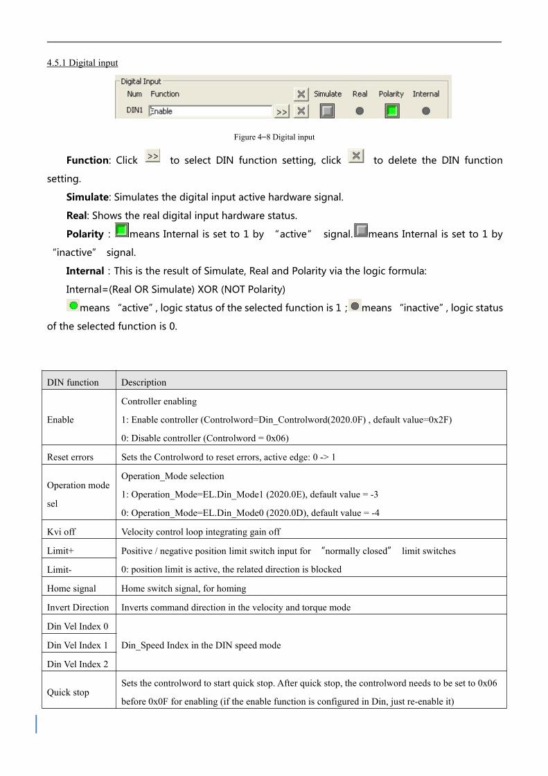
Figure 4–8 Digital input
Function: Click to select DIN function setting, click to delete the DIN function
setting.
Simulate: Simulates the digital input active hardware signal.
Real: Shows the real digital input hardware status.
Polarity: means Internal is set to 1 by “active” signal. means Internal is set to 1 by
“inactive” signal.
Internal:This is the result of Simulate, Real and Polarity via the logic formula:
Internal=(Real OR Simulate) XOR (NOT Polarity)
means “active”, logic status of the selected function is 1; means “inactive”, logic status
of the selected function is 0.
DIN function Description
Enable
Controller enabling
1: Enable controller (Controlword=Din_Controlword(2020.0F) , default value=0x2F)
0: Disable controller (Controlword = 0x06)
Reset errors Sets the Controlword to reset errors, active edge: 0 -> 1
Operation mode
sel
Operation_Mode selection
1: Operation_Mode=EL.Din_Mode1 (2020.0E), default value = -3
0: Operation_Mode=EL.Din_Mode0 (2020.0D), default value = -4
Kvi off Velocity control loop integrating gain off
Limit+ Positive / negative position limit switch input for “normally closed” limit switches
0: position limit is active, the related direction is blockedLimit-
Home signal Home switch signal, for homing
Invert Direction Inverts command direction in the velocity and torque mode
Din Vel Index 0
Din_Speed Index in the DIN speed modeDin Vel Index 1
Din Vel Index 2
Quick stopSets the controlword to start quick stop. After quick stop, the controlword needs to be set to 0x06
before 0x0F for enabling (if the enable function is configured in Din, just re-enable it)

Start homingStarts homing. Only makes sense if the controller is enabled. The controller returns to the
previous operation mode after homing.
Activate
command
Activates the position command. Controls bit 4 of the Controlword, e.g.
Controlword=0x2F->0x3F
Pre enable
For safety reasons, Pre_Enable can serve as a signal for indicating whether or not the entire
system is ready.
1: controller can be enabled
0: controller can not be enabled
Note
Relative/Absolute position control select (2020.0F) default setting is 0x2F. For
Control word definition, please refer to Chapter 6.1.
4.5.2 Digital output
Figure 4–9 Digital output
Function: Click to select the OUT function setting. Click to delete the OUT
function setting
Simulate: Simulates the digital output function logic status 1.
Real: Shows the real digital input hardware status. This is the result of Simulate, Polarity
and Logic State, means that digital input is ON, means that digital input is OFF.
Polarity: Inverts the logic status of the digital output function.
1 means Real physical digital output is set to ON by digital output function logic
status 1
0 means Real physical digital output is set to ON by digital output function logic
status 0
Real: This is the result of Simulate, Polarity and real input.
activate, logic state of corresponding function is 1.
deactivate, logic state of corresponding function is 0.
OUT function Description
Ready Controller is ready to be enabled
Error Controller error
Pos ReachedUnder position mode, position difference between Pos_Actual and
Pos_Target<Target_Pos_Window(6067.00),duration>=Position_Window_time(6068.00)

Zero Speed|Speed_1ms(60F9.1A)|<=Zero_Speed_Window(2010.18) and
duration >=Zero_Speed_Time(60F9.14)
Motor brakeSignal for controlling the motor brake. By this signal an external relay can be controlled, by
which the motor brake is controlled. (see chapter 3.2.4).
Speed Reached |Speed_Error(60F9.1C)|<Target_Speed_Window(60F9.0A)
Enc IndexEncoder position is inside a range around the index position. This range is defined by
Index_Window(2030.00).
Speed Limit In torque mode actual speed reached Max_Speed(607F.00)
Driver Enabled Controller enabled
Position Limit Position limit function is active
Home Found Home found
4.6 Scope
The scope function is for sampling the selected objects’ value with a flexible sample cycle
(defined by Sample Time) and a flexible total sample number (defined by Samples)
During operation, if performance does not meet the requirement or any other unexpected
behaviour occurs, it’s highly advisable to use the scope function to do the analysis.
Click Controller-->Scope or click to open the scope window
Trig offset: Number of samples before the trigger event occurs.
Object: Maximum 64-bit length data can be taken in one sample, e.g.: 2 Int32 objects bit
or 4 Int16 objects.
Single: means sample for one trigger event only. means sample
continuously.
Zoom in / zoom out the oscillogram: Press the right mouse key and drag to lower right /
upper left. Left mouse click on activates the horizontally drag mode, the icon changes to
and inside the oscillogram display area the mouse cursor changes to finger shape. A
zoomed oscillogram can be moved then in horizontal direction by pressing the left mouse
button and dragging to left/right.
Left mouse click on or any zoom-in or zoom-out action cancels the drag mode
automatically.
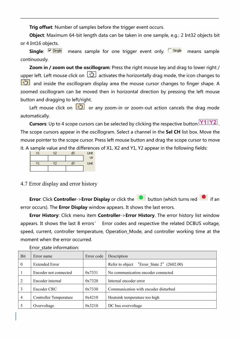
Cursors: Up to 4 scope cursors can be selected by clicking the respective button: .
The scope cursors appear in the oscillogram. Select a channel in the Sel CH list box. Move the
mouse pointer to the scope cursor. Press left mouse button and drag the scope cursor to move
it. A sample value and the differences of X1, X2 and Y1, Y2 appear in the following fields:
4.7 Error display and error history
Error: Click Controller->Error Display or click the button (which turns red if an
error occurs). The Error Display window appears. It shows the last errors.
Error History: Click menu item Controller->Error History. The error history list window
appears. It shows the last 8 errors’ Error codes and respective the related DCBUS voltage,
speed, current, controller temperature, Operation_Mode, and controller working time at the
moment when the error occurred.
Error_state information:
Bit Error name Error code Description
0 Extended Error Refer to object “Error_State 2”(2602.00)
1 Encoder not connected 0x7331 No communication encoder connected
2 Encoder internal 0x7320 Internal encoder error
3 Encoder CRC 0x7330 Communication with encoder disturbed
4 Controller Temperature 0x4210 Heatsink temperature too high
5 Overvoltage 0x3210 DC bus overvoltage

6 Undervoltage 0x3220 DC bus undervoltage
7 Overcurrent 0x2320 Power stage or motor short circuit
8 Chop Resistor 0x7110 Overload, brake chopper resistor
9 Following Error 0x8611 Max. following error exceeded
10 Low Logic Voltage 0x5112 Logic supply voltage too low
11 Motor or controller IIt 0x2350 Motor or power stage IIt error
12 Overfrequency 0x8A80 Pulse input frequency too high
13 Motor Temperature 0x4310 Motor temperature sensor alarm
14 Encoder information 0x7331 No encoder connected or no encoder communication reply
15 EEPROM data 0x6310 EEPROM checksum fault
Error_state2 information:
Bit Error name Error code Description
0 Current sensor 0x5210 Current sensor signal offset or ripple too large
1 Watchdog 0x6010 Software watchdog exception
2 Wrong interrupt 0x6011 Invalid interrupt exception
3 MCU ID 0x7400 Wrong MCU type detected
4 Motor configuration 0x6320 No motor data in EEPROM / motor never configured
5 Reserved
6 Reserved
7 Reserved
8 External enable 0x5443DIN "pre_enable" function is configured, but the DIN is inactive
when the controller is enabled / going to be enabled
9 Positive limit 0x5442Positive position limit (after homing) – position limit only causes
error when Limit_Function (2010.19) is set to 0.
10 Negative limit 0x5441Negative position limit (after homing) position limit only causes
error when Limit_Function(2010.19) is set to 0.
11 SPI internal 0x6012 Internal firmware error in SPI handling
12 Reserved
13Closed loop
direction0x8A81
Different direction between motor and position encoder in closed
loop operation by a second encoder.

14 Reserved
15 Master counting 0x7306 Master encoder counting error

Chapter 5 Operation mode
5.1 Velocity mode (-3, 3)
There are 2 kinds of velocity mode: -3 and 3. The velocity command can be specified via
Target_Speed or analog input (analog speed mode), or via digital input (DIN speed mode).
Table 5–1 Velocity mode
Internal
addressType Name Description value
60600020 Integer8Operation
mode
-3: The velocity command is specified directly
by Target_Speed. Only the velocity control loop
is active.
3: The velocity command is specified by
Target_Speed with profile acceleration and
profile deceleration. Velocity- and position
control loops are active
-3 and 3
60400010 Unsigned16Control
word
0x0F: Enable the controller ;0x06: Disable the
controller0x0F
60FF0020 Integer32 Target-speed Target velocity, cannot over motor rated speed User defined
60810020 Unsigned32 Profile_Acc Active in mode 1 and 3Default as
100rps/s
60830020 Unsigned.32 Profile_Dcc Active in mode 1 and 3Default as
100rps/s
In software "Basic operation" window, we can find these parameters and set, on the 6th,
7th, 10th, 11th, 12th, respectively.

Figure 5-1 “Basic operation” window
5.1.1 Analog speed mode
The analog speed object window in the PC software can be accessed via menu item
Controller->Control Modes->Analog Speed Mode.
Table 5–2 Analog speed mode
Internal
addressType Name Description Value
250.0610 Unsigned16 ADC1_Buff[1] AIN1 input real data
Only read
25020F10 Integer16 Analog1_outAIN1 valid input; analog input signal1 (AIN1)
input voltage after filter, deadband and offset
25010710 Unsigned16 ADC2_Buff[1] AIN2 input real data
25021010 Integer16 Analog2_outAIN2 valid input; analog input signal2 (AIN2),
input voltage after filter, deadband and offset
25020110 Unsigned16 Analog1_Filter AIN1 filter (unit: ms)
User
defined2FF01D10 Integer16 Analog1_Dead_V AIN1 deadband (unit: 0.01V)
2FF01E10 Integer16 Analog1_Offset_V AIN1 offset (unit: 0.01V)

25020410 Unsigned16 Analog2_Filter AIN2 filter (unit: ms)
2FF01F10 Integer16 Analog2_Dead_V AIN2 deadband (unit: 0.01V)
2FF02010 Integer16 Analog2_Offset_V AIN2 offset (unit: 0.01V)
25020A10 Integer16 Analog_Speed_Factor AIN speed factor
25020708 Unsigned8 Analog_Speed_Con
0: analog velocity control OFF, velocity
control via Target_Speed(60FF.00)
1: Speed control via AIN1
2: Speed control via AIN2
1 or 2
25020D10 Integer16 Analog_Dead_HighDefault is 0, if it's NOT 0, Analog_out>
Analog_Dead_High is treated as 0
User
defined
25020E10 Integer16 Analog_Dead_LowDefault is 0, if it's NOT 0, Analog_out<
Analog_Dead_Low is treated as 0
60600008 Integer8 Operation mode 4: Torque mode
60400010 Unsigned16 Controlword Driver enable
Figure 5-2 “Analog Speed Mode”window
For convenience, some new names are used in the formula. Definitions:
AIN1_in: AIN1 input voltage after filter and offset
AIN2_in: AIN2 input voltage after filter and offset
Analog_out: Analog1_out or Analog2_out, depends on wiring and Analog_Speed_Con setting;
It’s the result of AIN real input, filter, offset and deadband.
Final result:
Analog_Speed control ON:
If Analog_out is not limited by Analog_Dead_High or Analog_Dead_Low:
Target speed[rpm]=Analog_out[V]*Analog_Speed_Factor[rpm/V]; otherwise Target
speed[rpm]=0.
Analog_MaxTorque control ON:
Max torque[Nm]=Analog_out[V]*Analog_MaxT_Factor[Nm/V]
Example:
Setting: Analog1_Dead=1V, Analog1_Offset=2V, Analog_Speed_Factor=100rpm/V,
Analog_Speed_Con=1, Analog_Dead_High=0V; Analog_Dead_Low=0V;
Where AIN1 input voltage is 5V:
AIN1_in=5V–2V=3V, |AIN1_in| >Analog1_Dead, so Analog1_out=3V–1V=2V;
Target speed=2*100=200rpm.
Where AIN1 input voltage is -5V:
AIN1_in=-5V–2V=-7V, |AIN1_in|>Analog1_Dead, so Analog1_out=-7V+1V=-6V;
Target speed=-6*100=-600rpm.
5.1.2 DIN Speed mode
The Din_Speed object window in PC software can be accessed from menu item
Controller->Control Modes->DIN Speed Mode.
To make the DIN Speed Mode available, at least one of the following has to be configured to
DIN: Din Vel Index0, Din Vel Index1, Din Vel Index2.
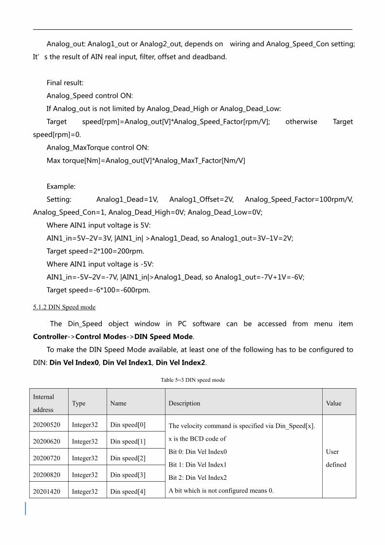
Table 5–3 DIN speed mode
Internal
addressType Name Description Value
20200520 Integer32 Din speed[0] The velocity command is specified via Din_Speed[x].
x is the BCD code of
Bit 0: Din Vel Index0
Bit 1: Din Vel Index1
Bit 2: Din Vel Index2
A bit which is not configured means 0.
User
defined
20200620 Integer32 Din speed[1]
20200720 Integer32 Din speed[2]
20200820 Integer32 Din speed[3]
20201420 Integer32 Din speed[4]

20201520 Integer32 Din speed[5]
20201620 Integer32 Din speed[6]
20201720 Integer32 Din speed[7]
Example:
I/O configuration:
Figure 5–3 IO configuration
Figure 5–4 IO“DIN speed mode”window
Table 5–4 DIN Speed mode
Internal address Type Name Value Unit
20200E08 Integer8 Din mode 1 -3
20200732 Integer32 Din speed [2] 500 rpm
Din Vel Index0=0; Din Vel Index1=1; Din Vel Index2=0. As soon as DIN1 is active, the
controller runs the motor in the velocity mode(Operation_Mode=-3) at 500rpm speed if there
aren’t any unexpected errors or limits.

5.2 Torque mode (4)
In the torque mode, the CD3 motor controller causes the motor to rotate with a specified
torque value.
Table 5–5 Torque mode
Internal
addressType Name Description Value
60600008 Integer8Operation_mo
de4
60710010 Integer16Target_Torque
%
Target torque,
percentage of rated torque
User
define
60400010 Unsigned16 Controlword Enable driver 0x0F
5.2.1 Analog torque mode
In the analog torque mode, the CD3 motor controller controls motor torque and / or maximum
torque by means of analog input voltage.
The analog torque object window in the PC software can be accessed via menu item
Controller->Control Modes->Analog Torque Mode.
Figure 5–5 “Analog torque mode”window

Table 5–6 Analog torque mode
Internal
addressType Name Description Value
25010610 Unsigned16 ADC1_Buff[1] AIN1 real input voltage
Read
25020F10 Integer16 Analog1_out
AIN1 valid input, analog input signal1
(AIN1), input voltage after filter, deadband
and offset
25010710 Unsigned16 ADC2_Buff[1] AIN2 input real data
25021010 Integer16 Analog2_out
AIN2 valid input, analog input signal2
(AIN2), input voltage after filter, deadband
and offset
25020110 Unsigned16 Analog1_Filter AIN1 filter (unit: ms)
User
defined
25020210 Integer16 Analog1_Dead_V AIN1 deadband (unit: 0.01V)
25020310 Integer16 Analog1_Offset_V AIN1 offset (unit: 0.01V)
25020410 Unsigned16 Analog2_Filter AIN2 filter (unit: ms)
25020510 Integer16 Analog2_Dead_V AIN2 deadband (unit: 0.01V)
25020610 Integer16 Analog2_Offset_V AIN2 offset(unit: 0.01V)
25020B10 Unsigned16Voltage_Torque_Facto
rAIN-Torque factor (unit: mNM/V)
25020808 Unsigned 8 Analog_Torque_Con
0: Analog_Torque_control OFF, target torque
is specified by Target_Torque% (6071.00)
1: Torque control via AIN1
2: Torque control via AIN2
1 or 2
25020C10 Unsigned16 Voltage_MaxT_Factor AIN-MaxTorque factor (unit: mNM/V)User
define
0, 1, 225020908 Unsigned 8 Analog_MaxT_Con
0: Analog_MaxTorque control OFF
1: max. torque control via AIN1;
2: max. torque control via AIN2
60F60310 Unsigned16 Speed_Limit_Factor Influence max speed limit 0x60800010, if 10

value is bigger, limit is better, but if it is too
big, it will cause noise
60800010 Unsigned16 Max_Speed rpm Limit motor max speed
Note
Analog_MaxT_Con is not only used in operation mode 4. All operation modes can
use analog output to limit max torque output.
For convenience, some new names are used in the formula. The definitions are as follows:
AIN1_in: AIN1 input voltage after filter and offset.
AIN2_in: AIN2 input voltage after filter and offset.
Analog_out: Analog1_out or Analog2_out, depends on wiring and Analog_Torque_Con setting.
It’s the result of AIN real input, filter, offset and deadband.
Final Result:
When Analog_Torque control is ON, target
torque[Nm]=Analog_out[V]*Analog_Torque_Factor[Nm/V].
When Analog_MaxTorque control is ON, max.
torque[Nm]=Analog_out[V]*Analog_MaxT_Factor[Nm/V].
5.3 Position mode (1)
In the position mode, the CD3 motor controller causes the motor to rotate to an absolute or
relative position. The position / velocity command is specified via Target_Position / Profile_Speed or
via position table (Position Table Mode)
Table 5–7 Position mode
Internal
addressType Name Description Value
60600008 Integer8Operation_
ModeWay of control motor 1
607A0020 Integer32Target_Pos
itionTarget absolute / relative position User defined
60810020 Unsigned32Profile_Sp
eedProfile speed for positioning User defined

60400010 Unsigned16Controlwor
d
Switch from 0x2F to 0x3F:Absolute position;
Switch from 0x4F to 0x5F:Relative position
0x2F->0x3F or
0x4F->0x5F
5.4 Pulse mode (-4)
In the pulse mode, the target velocity command is specified via the pulse input with gear ratio.
Table 5–8 Pulse mode
Internal
addressType Name Description Value
6060000
8Integer8 Operation_Mode Operation mode -4
2508011
0Integer16 Gear_Factor[0]
Gear_ratio=Gear_Factor/Gear_DividerUser
define2508021
0
Unsigned1
6Gear_Divider[0]
6040001
0
Unsigned1
6Controlword Enable driver 0x2F:
2508030
8Unsigned 8 PD_CW
Pulse train mode
0: CW / CCW
1: Pulse / direction
2: A / B (incremental encoder)
0, 1, 2
2508061
0
Unsigned1
6PD_Filter Pulse filter (ms)
User
define2508081
0
Unsigned1
6
Frequency_Chec
k
Frequency limit (inc/ms), if pulse count (in 1
ms) is greater than Frequency_Check, over
frequency error occurs.
Table 5–9 PD_CW schematic
Pulse mode Forward Reverse
P/D

CW/CCW
A/B
Note
Forward means positive position counting’s defaulted to the CCW direction. You
can set Invert_Dir(607E.00) to 1 in order to invert the direction of motor shaft
rotation.
Figure 5-6 Pulse filter principle
5.5 Homing mode (6)
For some applications, the system needs to start from the same position every time after
power on. In the homing mode, the user can specify the system ’ s home position and a zero
(starting) position.
Click menu item Controller->Control Modes->Homing definition, and the following window
appears:

Figure 5–7 Homing settings
Select a home trigger under Homing Trigger. The related items appear in the configuration
area. Select a suitable item according to mechanical design and wiring. The Appropriate
homing_method then appears in the Pre-Set Home Method box. If Disabled is selected under
homing trigger, you enter a number directly to the Pre-Set Home Method field. Click
to set it to the controller.
The corresponding diagram of the Pre-Set Home method appears in the middle area.
All homing mode objects are listed in following table:
Table 5–10 Homing mode
Internal
addressName Type Value Description
607C00
20Home_Offset Integer32
User
defineZero position offset to the home position
6098000 Homing_Metho Integer 8 User Way of homing method

Note
Homing_Power_On=1 causes the motor to start rotating as soon as the controller is
enabled after power on or reboot. Consider all safety issues before using.
Home_N_Blind:
If the homing_method needs home signal (position limit / home switch) and index signal,
Home_N_Blind function can avoid the homing result being different with the same mechanics,
when the Index signal is very close to the home signal. By setting to 1 before homing, the controller
detects a suitable blind window for homing automatically. It can be used to assure that homing
results are always the same.
During homing, the index signal inside this blind window is ignored after the home signal is
found. Home_N_Blind (0:0rev;1:0.25rev;2:0.5rev) is defaulted to 0. If it's set to 1, it’s changed to 0
8 d define
6099022
0
Homing_Speed
_Zero
Unsigned2
0
User
define
Velocity for finding home position and zero
position
6099030
8
Homing_Power
_OnUnsigned 8 0,1
1: Start homing after power on or reboot and
first controller enable
609A00
20
Homing_Accel
aration
Unsigned3
2
User
define
Profile deceleration and acceleration during
homing
6099012
0
Homing_Speed
_Switch
Unsigned3
2
User
define
Velocity for searching position limit switch /
home switch signal
6099041
0
Homing_Curre
ntInteger8
User
defineMax. current during homing
6099050
8
Home_Offset_
ModeUnsigned 8 0,1
0: Go to the homing offset point. The actual
position will be 0.
1: Go to the home trigger point. The actual
position will be -homing offset.
6099060
8Home_N_Blind Unsigned 8 0,1
Home blind window
0: 0rev
1: 0.25rev
2: 0.5rev
6060000
8
Operation_Mod
eInteger8 6 Operation mode
6040001
0Controlword
Unsigned1
6
0x0F->0x
1FEnable driver
or 2 after homing depending on the index signal position relative to the homing signal.This
parameter needs to be saved. If the mechanical assembly is changed or the motor has been
replaced, just set it to 1 again for initial homing.
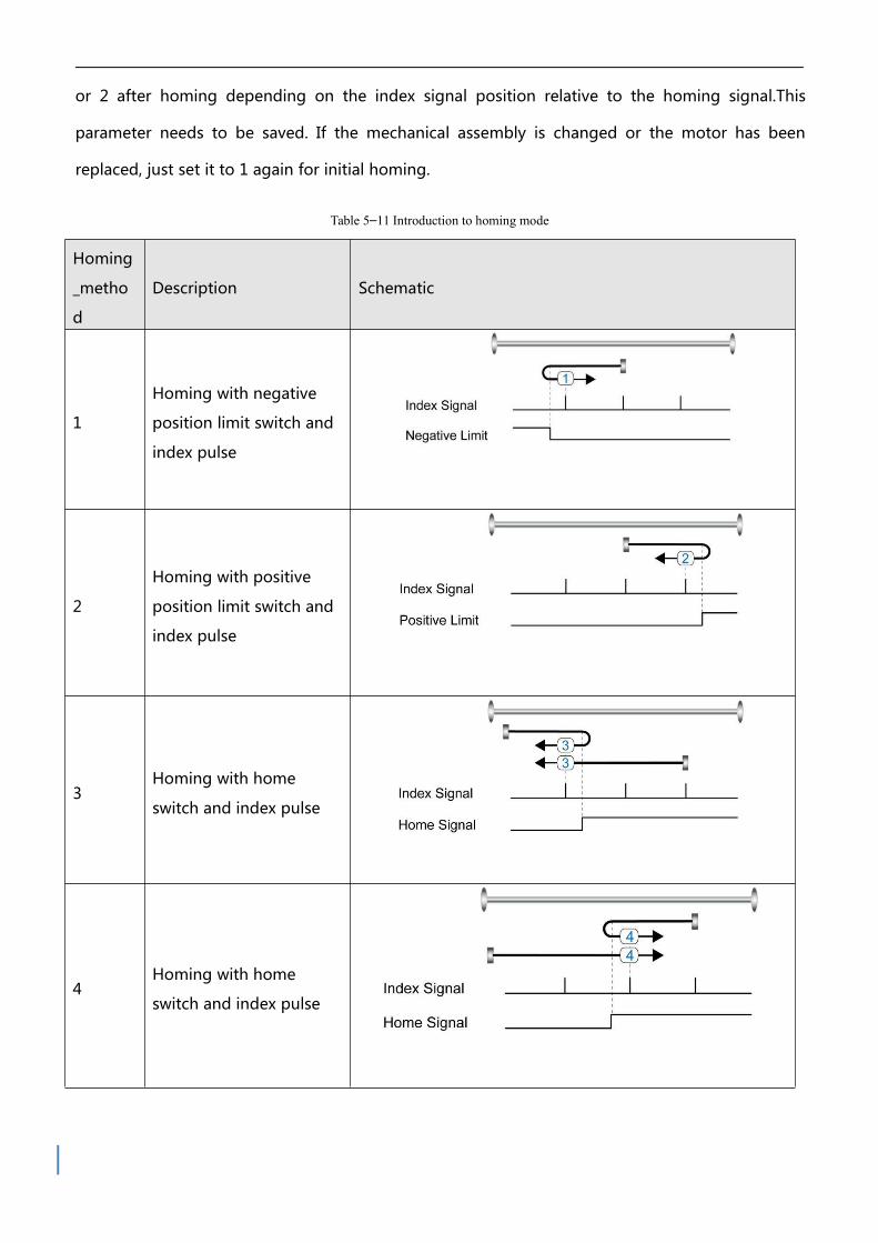
Table 5–11 Introduction to homing mode
Homing
_metho
d
Description Schematic
1
Homing with negative
position limit switch and
index pulse
2
Homing with positive
position limit switch and
index pulse
3Homing with home
switch and index pulse
4Homing with home
switch and index pulse

5Homing with home
switch and index pulse
6Homing with home
switch and index pulse
7
Homing with positive
position limit switch,
home switch and index
pulse
8
Homing with positive
position limit switch,
home switch and index
pulse
9
Homing with positive
position limit switch,
home switch and index
pulse

10
Homing with positive
position limit switch,
home switch and index
pulse
11
Homing with negative
position limit switch,
home switch and index
pulse
12
Homing with negative
position limit switch,
home switch and index
pulse
13
Homing with negative
position limit switch,
home switch and index
pulse
14
Homing with negative
position limit switch,
home switch and index
pulse

17Homing with negative
position limit switch
18Homing with positive
position limit switch
19
Homing with home
switch
20Homing with home
switch
21Homing with home
switch

22Homing with home
switch
23
Homing with positive
position limit switch and
home switch
24
Homing with positive
position limit switch and
home switch
25
Homing with positive
position limit switch and
home switch
26
Homing with positive
position limit switch and
home switch

27
Homing with negative
position limit switch and
home switch
28
Homing with negative
position limit switch and
home switch
29
Homing with negative
position limit switch and
home switch
30
Homing with negative
position limit switch and
home switch
33, 34 Homing with index pulse
35Homing to actual
position

-17, -18Homing via mechanical
limit

Chapter 6 Tuning of the servo system control
Currentloop
PWM
Motor
Feedback
Notch filter
Observer
Lowpas
s
filt
erdx/dt
+
+
+
Speed demandanalog1analog2
Torquedemandanalog1analog2
Profile generator
Current
Dem
andlow
pass
Speeddem
andlow
passfilter
K
pp
K
vff
kvp
Average filter
Profile position
Actualposition
+
Kaff
-
-
+
+
+
+
+
+
Real speed
Currentfeedback
DCBUS+
DCBUS-
POWER
Profile speed
kvi
++
+
i-limit
Acceleration feedforward
1 order
2 order
K-load
∫
dt
+Kvff
Kpp
+
+
∫dt
Dx/dt
+
-
- +
+
+
+
+++
Figure 6–1 Servo system control block diagram
Figure 6-1 shows the servo system control block diagram. It can be seen from the figure that
the servo system generally includes three control loops: current loop, velocity loop and position
loop.
The adjustment process of a servo system is used to set loop gain and filters to match the
mechanical characteristics, and finally to prevent the entire system from oscillating, to permit it to
follow commands quickly and to eliminate abnormal noise.
6.1 Tuning of velocity loop
Table 6–1 List of velocity loop parameters
Internal
addressName Description
Defau
ltRange
60F9011
0Kvp[0]
Proportional velocity loop gain
Can be displayed in Hz in the PC tool can if
the inertia ratio is right.
/1~3276
7

60F9021
0Kvi[0] Integral velocity loop gain / 0-1023
60F9071
0Kvi/32
Integral velocity loop gain of in a smaller unit
of measure/ 0-32767
60F9050
8Speed_Fb_N
Used to set Velocity feedback filter
bandwidth
Filter bandwidth=100+Speed_Fb_N*20
7 0~45
60F9060
8Speed_Mode
Used to set the velocity feedback mode
0: 2nd order FB LPF
1: Directly feedback the original velocity
2: Velocity feedback after velocity observer
4: Velocity feedback after 1st order LPF
10: Velocity feedback after 2nd order LPF
and the velocity command is filtered by a 1st
order LPF. Both filters have the same
bandwidth. 11: The velocity command is
filtered by a 1st order LPF
12: Velocity feedback after velocity observer,
the velocity command is filtered by a 1st
order LPF
14: Velocity feedback after 1st order LPF and
the velocity command is filtered by a 1st
order LPF. Both filters have the same
bandwidth
1 /
60F9150
8Output_Filter_N
A 1st order lowpass filter in the forward path
of the velocity loop1 1-127
60F9082
0Kvi_Sum_Limit Integral output limit of the velocity loop / 0-2^15
Step of Velocity loop tuning is shown below:
Velocity feedback filter adjustment
The velocity feedback filter can reduce noise that comes from the feedback path, e.g. reduce
encoder resolution noise. The velocity feedback filter can be configured as 1st and 2nd order via
the Speed_Mode for different applications. The 1st order filter reduces noise to a lesser extent, but
its also results in less phase shifting so that velocity loop gain can be set higher. The 2nd order filter
reduces noise to a greater extent, but its also results in more phase shifting so that velocity loop

gain can be limited.
Normally, if the machine is stiff and light, we can use the 1st feedback filter or disable the
feedback filter. If the machine is soft and heavy, we can use the 2nd order filter.
If there’s too much motor noise when velocity loop gain is adjusted, velocity loop feedback
filter parameter Speed_Fb_N can be reduced accordingly. However, velocity loop feedback filter
bandwidth F must be more than twice as large as the velocity loop bandwidth. Otherwise, it may
cause oscillation. Velocity loop feedback filter bandwidth F=Speed_Fb_N*20+100 [Hz].
Output filter adjustment
The output filter is a 1st order torque filter. It can reduce the velocity control loop to output
high frequency torque, which may stimulate overall system resonance.
The user can try to adjust Output_Filter_N from small to large in order to reduce noise.
The filter bandwidth can be calculated using the following formula.
Velocity loop bandwidth calculation
Use the following formula to calculate velocity loop bandwidth:
kt motor torque constant, unit: Nm/Arms*100
J inertia, unit: kg*m^2*10^6
Fbw Velocity loop bandwidth, unit: Hz
Imax max motor current I_max(6510.03) as DEC value
encoder resolution of the encoder
Integral gain adjustment
Integral gain is used to eliminate static error. It can boost velocity loop low frequency gain, and
increased integral gain can reduce low frequency disturbance response.
Normally, if the machine has considerable friction, integral gain (kvi) should be set to a higher
value.
If the entire system needs to respond quickly, integral should be set to a small value or even 0,
and the gain switch should be used.
Adjust Kvi_sum_limit
Normally the default value is fine. This parameter should be added if the application system

has a big extend force, or should be reduced if the output current is easily saturation and the
saturation output current will cause some low frequency oscillation.
6.2 Tuning of position loop
Table 6–2 List of position loop parameters
Internal
addressName Description Default Range
60FB011
0Kpp[0]
Proportional position loop gain.
Used to set the position loop response.
unit: 0.01Hz
10 0~32767
60FB021
0K_Velocity_FF
0 means no feedforward, 1000 means 100%
feedforward.100 0~100
60FB031
0K_Acc_FF
The unit only is right if the inertia ratio is
correctly set.
If the inertia ratio is unknown, set
K_Acc_FF(60FB.03) instead.
/ 0-32767
60FB051
0Pos_Filter_N
The time constant of the position demand
LPF unit: ms1 1~255
6065002
0
Max_Following_
Error_16
Maximum allowable error,
Max_Following_Error (6065.00) = 100 *
Max_Following_Error_16
10000 /
Step of Position loop tuning is shown below:
Position loop proportional gain adjustment
Increasing position loop proportional gain can improve position loop bandwidth, thus
reducing positioning time and following error, but setting it too high will cause noise or even
oscillation. It must be set according to load conditions. Kpp = 103 * Pc_Loop_BW, Pc_Loop_BW is
position loop bandwidth. Position loop bandwidth cannot exceed velocity loop bandwidth.
Recommended velocity loop bandwidth: Pc_Loop_BW<Vc_Loop_BW / 4, Vc_Loop_BW.
Position loop velocity feedforward adjustment
Increasing the position loop velocity feedforward can reduce position following error, but can
result in increased overshooting. If the position command signal is not smooth, reducing position
loop velocity feedforward can reduce motor oscillation.
The velocity feedforward function can be treated as the upper controller (e.g. PLC) have a

chance to directly control the velocity in a position operation mode. In fact this function will
expend part of the velocity loop response ability, so if the setting can’t match the position loop
proportional gain and the velocity loop bandwidth, the overshot will happen.
Besides, the velocity which feedforward to the velocity loop may be not smooth, and with
some noise signal inside, so big velocity feedforward value will also amplified the noise.
Position loop acceleration feedforward
It is not recommended that the user adjust this parameter. If very high position loop gain is
required, acceleration feedforward K_Acc_FF can be adjusted appropriately to improve
performance.
The acceleration feedforward function can be treat as the upper controller (e.g. PLC) have a
chance to directly control the torque in a position operation mode. in fact this function will expend
part of the current loop response ability, so if the setting can ’ t match the position loop
proportional gain and the velocity loop bandwidth, the overshot will happen.
Besides, the acceleration which feedforward to the current loop can be not smooth, and with
some noise signal inside, so big acceleration feedforward value will also amplified the noise.
Acceleration feedforward can be calculated with the following formula:
ACC_%=6746518/ K_Acc_FF/ EASY_KLOAD*100
ACC_%: the percentage which will be used for acceleration feedforward.
K_Acc_FF(60FB.03): the final internal factor for calculating feedforward.
EASY_KLOAD(3040.07): the load factor which is calculated from auto-tuning or the right inertia
ratio input.
Note
The smaller the K_Acc_FF, the stronger the acceleration feedforward.
Smoothing filter
The smoothing filter is a moving average filter. It filters the velocity command coming from the
velocity generator and makes the velocity and position commands more smooth. As a
consequence, the velocity command will be delayed in the controller. So for some applications like
CNC, it’s better not to use this filter and to accomplish smoothing with the CNC controller.
The smoothing filter can reduce machine impact by smoothing the command. The
Pos_Filter_N parameter define the time constant of this filter in ms. Normally, if the machine system
oscillates when it starts and stops, a larger Pos_Filter_N is suggested.

Notch filter
The notch filter can suppress resonance by reducing gain around the resonant frequency.
Antiresonant frequency=Notch_N*10+100
Setting Notch_On to 1 turns on the notch filter. If the resonant frequency is unknown, the user
can set the maximum value of the d2.14 current command small, so that the amplitude of system
oscillation lies within an acceptable range, and then try to adjust Notch_N and observe whether the
resonance disappears.
Resonant frequency can be measured roughly according to the Iq curve when resonance
occurs on the software oscilloscope.
Table 6–3 Notch filter list
Internal
addressName Description Default Range
60F90308 Notch_N
Used to set the frequency of the internal notch
filter to eliminate mechanical resonance generated
when the motor drives the machine. The formula is
F=Notch_N*10+100. For example, if mechanical
resonance frequency F=500 Hz, the parameter
setting should be 40.
45 0~90
60F90408 Notch_On
Used to turn on or turn off the notch filter.
0:Turn on the notch filter
1:Turn off the notch filter
0 0~1
6.3 Factors which influence tuning results
The control command is created by the upper controller (e.g. PLC):
The control command should be smooth as much as possible, and must be correct. For
example, the control command should not create the acceleration commands (inside the position
commands) that the motor cannot provide. Also, the control command should follow the
bandwidth limit of the control loop.
The machine design:
In the actual application, performance is normally limited by the machine. Gaps in the gears,
soft connection in the belts, friction in the rail, resonance in the system – all of these can influence
final control performance. Control performance affects the machine’s final performance, as well as

precision, responsiveness and stability. However, final machine performance is not only determined
by control performance.

yes
yes
no
Overshoot
Current near to
target currentyes
Start
Set motor No and
initialize parameters E
Home
Auto-tuning
Set profile_speed, profile_acc,
profile_dcc
Current is less
than the rated
current
Check motor friction,
gear ratio
Reduce profile_acc,
profile_dcc, target speed
Cause following error & iit
Value is bigger, current is
bigger
Compare original speed &
target speed feedback
Not overshoot
Increase kvp, kvi
Increase acc, dcc
Small oscillation is
permitted
Decrease kvp, kvi
Increase kvp, kvi
no
Oscillationno
no
no
Home current can be adjusted to
twice of motor rated current,
rated current (4.6A) is max home
current (9.2A)
yes
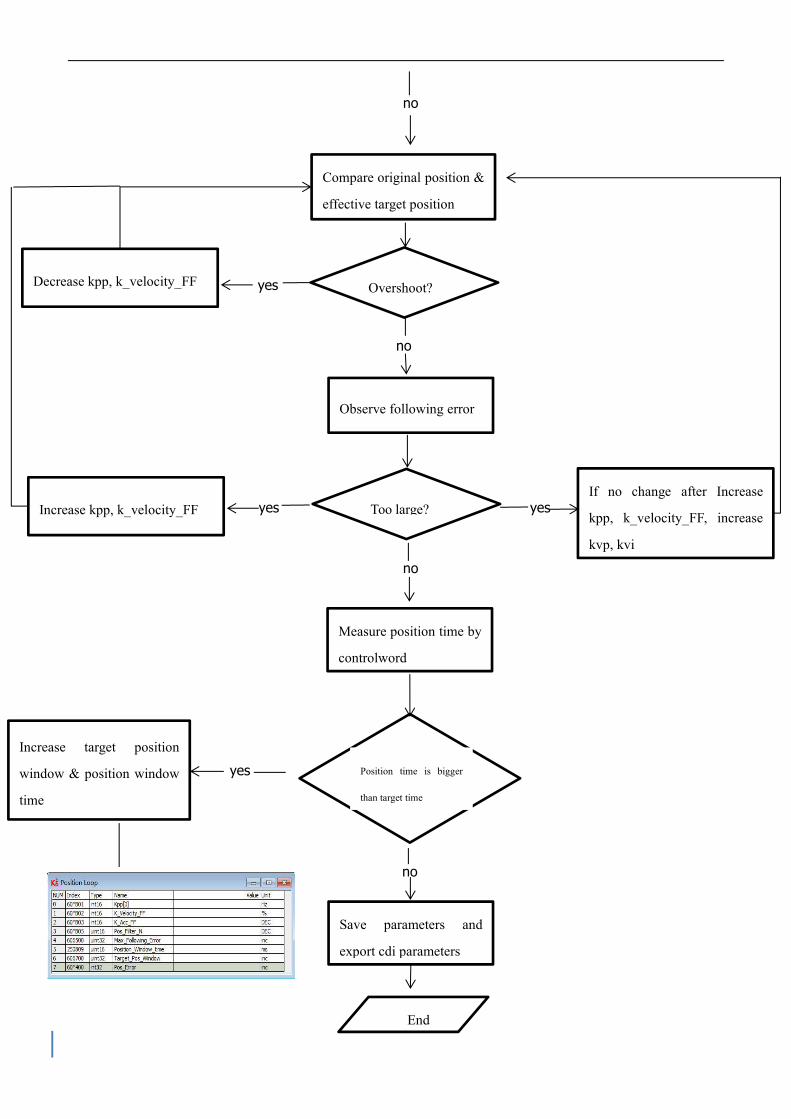
no
yes
no
yes yes
no
yes
no
Observe following error
Decrease kpp, k_velocity_FF
Too large?If no change after Increase
kpp, k_velocity_FF, increase
kvp, kvi
Position time is bigger
than target time
Overshoot?
Increase target position
window & position window
time
Compare original position &
effective target position
Increase kpp, k_velocity_FF
Measure position time by
controlword
Save parameters and
export cdi parameters
End

Chapter 7 Alarms and troubleshooting
When driver generate an alarm, red light, ERR, will shine.
If you need more detailed information about errors and error history, please connect the
controller to the PC via RS232.
Table 7–1 Alarm codes of Error_State 1
Alar
mCod
e
Name Reason Troubleshooting
000.
1Extended Error
Errors occurs in
Error_State2
Press the SET key to enter
Error_State2 (d1.16), read the error bit,
check the error meaning in table 7-2.
000.
27380
Encoder ABZ
signal incorrect
( suitable for
incremental
encoder motor)
Encoder ABZ wiring is
wrong or disconnected Check encoder cable is correctly
connected
Check if corresponding pins of
encoder cable is on ( refer servo
product menu)
Encoder
communication
incorrect (suitable
for magnetoelectric
encoder motor)
The encoder wiring is
incorrect or
disconnected.
000.
47381
Encoder UVW
signal incorrect
( suitable for
incremental
encoder motor)
Encoder UVW wiring is
wrong or disconnected
Check encoder cable is correctly
connected
Check if corresponding pins of
encoder cable is on ( refer servo
product menu)
Change motor
Encoder internal
(suitable for
magnetoelectric
encoder motor)
Encoder internal is
incorrect or encoder is
broken
000. 7306 Encoder count Encoder is interfered 1.Check encoder cable is correctly

8 wrong(suitable for
incremental
encoder motor)
connected (different from motor PE
cable)
2.Make sure the equipment is well
grounded
3.Use isolated power supply to provide
power
Encoder CRC
(suitable for
magnetoelectric
encoder motor)
001.
04210
Controller
temperature
The temperature of
controller ’ s power
module has reached the
alarm value
Add fan , improve the cooling
environment of the controller.
Add driver installment distance
Vertically install driver
002.
03210 Overvoltage
Supply power voltage
exceeds the allowable
input voltage range
Check if supply power is higher than
standard output voltage
Check to see if supply power voltage is
unstable
In case of emergency
stop, there is no external
braking resistor or
braking.
Connect suitable braking resistor
Open software "Driver"-> “ Panel
menu”->“(F005)controller setting”
Correctly set "brake resistor value" an
"brake resistor power"
Brake resistor is not
configured
Change Connect suitable braking
resistor
Open software "Driver"-> “ Panel
menu”->“(F005)controller setting”
Correctly set "brake resistor value" an
"brake resistor power"
004.
03220 Undervoltage
The power voltage input
is lower than the low
voltage protection alarm
value.
Check if power supply output power
can meet with the requirement
Change power supply of bigger power
008.
02320
Short circuit of
driver output
Short circuit of driver
UVW and PE output
Check if motor power cable
connection is correct
Driver is broken, change driver
010. 7110 Driver brake Not configure correct Open software "Driver"-> “ Panel

0 resistor is
abnormal
brake resistor parameters menu”->“(F005)controller setting”
Correctly set "brake resistor value" an
"brake resistor power"
020.
08611 Following error
Stiffness of control loop
is too small
Open software "Driver" "control loop"
"velocity loop" "position loop"
Increase "kpp[0]" "kvp[0]"
Motor UVW phase
sequence is incorrectExchanging wire of U and V
The controller and motor
together can’t match the
requirement of the
application
Change motor and driver with bigger
power
Max_Following_Error
is too small
Open software "Driver" "control loop"
"velocity loop" "position loop"
Increase "max_following_error"
(Ensure control loop parameters is
fine, user can change this parameter)
040.
05122 Low logic voltage
Logic voltage is less
than 18V,power supply
voltage is pulled down
Check if power supply output power
can meet with requirements
Change power supply with bigger
power
080.
02350
Motor or controller
IIt
The brake is not released
when the motor shaft is
rotating (only for brake
motor)
Check if brake cable wiring is correct
Check brake power can meet with the
requirements (output voltage is
DC24V, input current is 1A, output
power is bigger than 24W)
Machine equipment
stuck or excessive
friction
Cancel motor enable, or power off
driver
Please drag load to make it move back
and forth in motor's running route.
Ensure that there is no machine
equipment stuck or excessive friction
Add lubricate
Motor UVW phase
sequence is incorrect
Exchange motor wiring of phase U and
phase V

100.
0
8A8
0
Over input
frequency
External input pulse
frequency is too high
Reduce external pulse input frequency
When ensure safely use motor,
increase "Frequency_Check" ( Open
“Driver”->“Control modes”->“Pulse
mode”->“Frequency_Check”),
max 600
200.
04310 Motor temperature
The motor temperature
exceeds the specified
value
Reduce ambient temperature of the
motor and improve cooling conditions
Reduce acceleration and deceleration
Reduce load
400.
07122
Motor excitation
( suitable for
incremental
encoder)
Motor UVW phase
sequence is wrong
Exchange motor wiring of phase U and
phase V
Encoder is not connected Check encoder cable
Encoder
information
( suitable for
magnetoelectric
encoder)
Communication is
incorrect when the
encoder is initialized
Check encoder wiring, restart driver
The encoder type is
wrong, e.g. an unknown
encoder is connected
The data stored in the
encoder is wrong
The controller can ’ t
support the current
encoder type
800.
06310 EEPROM data
Data is damaged when
the power is turned on
and data is read from the
EEPROM
Open software“Driver”->“Init Save
Reboot”
Click “ Init Control Parameters ” ->
“Save Control Parameters”->“Save
Motor Parameters”->“Reboot”
Import cdi file by software
Table 7–2 Alarm codes of Error_State2 (extended)

Alar
m
CodeName Reason Trouble shooting
000.
1
0x52
10Current sensor
Current sensor signal
offset or ripple too big
Circuit of current sensor is damaged,
please contact the supplier
000.
2
0x60
10Watchdog
Software watchdog
exception
Please contact the supplier and try to
update the firmware
000.
4
0x60
11Wrong interrupt
Invalid interrupt
exception
Please contact the supplier and try to
update the firmware
000.
8
0x74
00MCU ID
Wrong MCU type
detectedPlease contact the supplier
001.
0
0x63
20
Motor
configuration
Motor type is not
auto-recognized, no
motor data in EEPROM
/ motor never
configured
Install a correct motor type to the
controller and reboot
010.
0
0x54
43External enable
DIN function
“ pre_enable ” is
configured, but the input
is inactive when the
controller is enabled or
should become enabled
Solve according to the reason
020.
0
0x54
42Positive limit
Positive position limit
(after homing), position
limit only causes error
when Limit_Function
(2010.19) is set to 0
Exclude the condition which causes
the limit signal
040.
0
0x54
41Negative limit
Positive position limit
(after homing), position
limit only causes error
when Limit_Function
(2010.19) is set to 0
Exclude the condition which causes
the limit signal
080. 0x60 SPI internal Internal firmware error Please contact the supplier

0 12 in SPI handling
200.
0
0x8A
81
Close loop
direction
Different direction
between motor and
position encoder
Change the encoder counting direction
800.
0
0x73
06Master counting
Master encoder counting
error
Ensure that the ground connection and
the encoder shield work well.

Chapter 8 List of motor controller parameters
Note
CANopen address is same as 232 communication address:
Use Index (16 bits address), Subindex (8 bit subaddress) to show register
addressing,
0x08 means that data length of register store is 1 Byte, 0x10 means that data
length of register store is 2 Byte, 0x20 means that data length of register store
is 4 Byte,
R: Read,W: Write,S:Save,M: Map,
A complete CANopen address format is : 60400010(controlword),
Modbus address is 4 bits Hexadecimal number
A complete Modbus address format is : 3100(controlword)
8.1 Mode and Control(0x6040)
Name CANopen Modbus RWS Data type Description
Controlwor
d60400010 3100 RWM Unsigned16
0x06:Power off motor
0x0F:Power on motor
0x0B : Quick stop , load stop -
voltage off
0x2F → 3F : Start absolute
positioning
0x4F→5F:Start relative positioning
0x103F:Start absolute positioning
while target position change
0x0F-1F:Home positioning
0X80:Clear internal shooting

Status
word60410010 3200 RM Unsigned16
Status word display driver state
bit0:Ready_on
bit1:Switch_on
bit2:Operation enable
bit3:Fault
bit4:Voltage_enable
bit5:Quick stop
bit6:Switch_disabled
bit8:Maunufacture0
bit9:Remote
bit10:Target_reached
bit11 :
Intlim_active(negative/positive
position limit actived)
bit12:Setpoint_Ack
bit13:Following_Error
bit14:Communication_Found
bit15:Reference_found
Operation
mode60600008 3500 RWM Integer8
Operation mode:
1:Position control
3:Speed control
4:Torque control
-3:Speed control (Quick fast mode)
-4:Pulse train control
6:Home mode
7 : Differential complementarity
based on CANopen
Absolute/R
elative
positioning
control
select
20200F 0CF0 RWS Unsigned16
When "Driver enable" function is
configured to Din and Din is 1,
“Controlword” (6040.00) will be
set;
0x2F:Absolute positioning control
0x4F:Relative positioning control

8.2 Data measuring
Note
0x606C0020,conversion between engineering unit and internal unit of common
objects DEC=[(RPM*512*Encoder_Resolution)/1875]
8.3 Target object(0x607A)
Name CANopen Modbus RWS Data type Description
Pos_Actual 60630020 3700 RM Integer32
Real current 60780010 3E00 RM Integer16
Status of
input port60FD0020 6D00 RM Unsigned32
bit0: negative limit switch
bit1: positive limit switch
bit2: home switch
bit3: interlock
Real speed 606C0020 3B00 RM Integer32 rpm
Name CANopenmodb
usRWS Data type Description
Invert
direction607E0008 4700 RWS Unsigned8
Invert motion
0:CCW is positive direction
1:CW is positive direction
Target
position607A0020 4000 RWM Integer32
Target position in position mode 1.
If controlword is set to start motion
and transfer to effective command
position inc
Profile
speed60810020 4A00 RWM Unsigned32
Speed of trapezoidal curve in work
mode 1
Target
speed60FF0020 6F00 RWM Integer32 Target speed in mode 3 and -3
Max speed 60800010 4900 RW Unsigned16 Default 5000rpm
Profile acc 60830020 4B00 RWSM Unsigned32 Default:610.352rps/s
Profile dec 60840020 4C00 RWSM Unsigned32 Default:610.352rps/s

Note
Speed address:0x60810020,0x60800020,0x60FF0020
Conversion between engineering unit and internal unit of common objects
DEC=[(rpm*512*Encoder_Resolution)/1875]
Acc & Dec address:60830020,60840020,
Conversion between engineering unit and internal unit of common objects
DEC=[(rps/s*65536*Encoder_Resolution)/4000000]
Current address:60710010,60730010
Conversion between engineering unit and internal unit of common objects
1Arms=(2048/Ipeak/1.414)DEC Ipeak is driver max current
8.4 Din speed/position(0x2020)
Target
torque60710010 3C00 RW Integer16
Torque command in torque mode ,
target_torque/rated_torque*100
(unit:%)
Group
current
loop
60F60810 5880 RWM Integer16 Current command in torque mode
Maximal
current
command
60730010 3D00 RWSM Unsigned16 Maximal current command, unit Arms
Name CANopen modbus RWS Data type Description
Din_Pos0 20200120 0C10 RWS Integer32
Din_Pos1 20200220 0C20 RWS Integer32
Din_Pos2 20200320 0C30 RWS Integer32
Din_Pos3 20200420 0C40 RWS Integer32
Din_Pos4 20201020 0D00 RWS Integer32
Din_Pos5 20201120 0D10 RWS Integer32
Din_Pos6 20201220 0D20 RWS Integer32
Din_Pos7 20201320 0D30 RWS Integer32
Din_Speed0 20200520 0C50 RWS Integer32
Din_Speed1 20200620 0C60 RWS Integer32
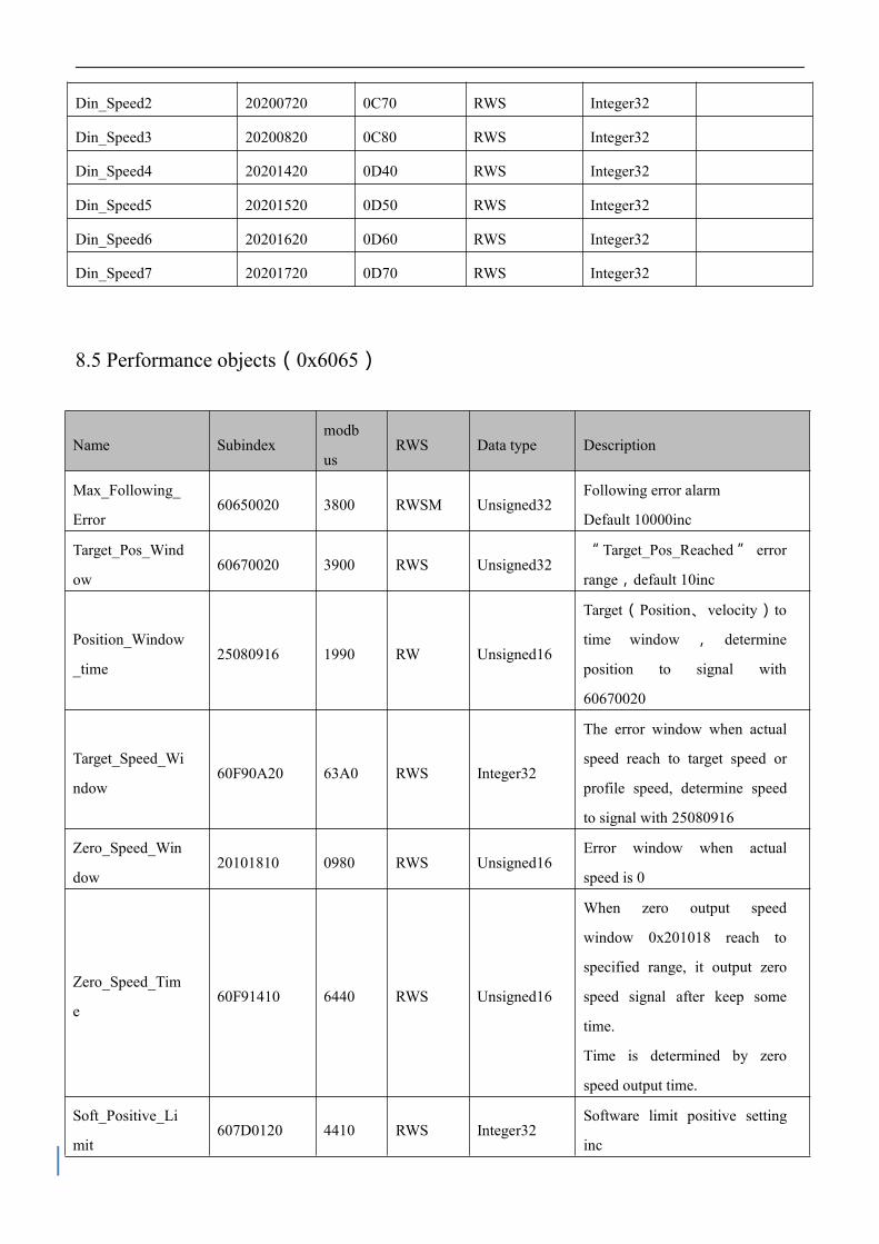
8.5 Performance objects(0x6065)
Din_Speed2 20200720 0C70 RWS Integer32
Din_Speed3 20200820 0C80 RWS Integer32
Din_Speed4 20201420 0D40 RWS Integer32
Din_Speed5 20201520 0D50 RWS Integer32
Din_Speed6 20201620 0D60 RWS Integer32
Din_Speed7 20201720 0D70 RWS Integer32
Name Subindexmodb
usRWS Data type Description
Max_Following_
Error60650020 3800 RWSM Unsigned32
Following error alarm
Default 10000inc
Target_Pos_Wind
ow60670020 3900 RWS Unsigned32
“ Target_Pos_Reached ” error
range,default 10inc
Position_Window
_time25080916 1990 RW Unsigned16
Target(Position、velocity)to
time window , determine
position to signal with
60670020
Target_Speed_Wi
ndow60F90A20 63A0 RWS Integer32
The error window when actual
speed reach to target speed or
profile speed, determine speed
to signal with 25080916
Zero_Speed_Win
dow20101810 0980 RWS Unsigned16
Error window when actual
speed is 0
Zero_Speed_Tim
e60F91410 6440 RWS Unsigned16
When zero output speed
window 0x201018 reach to
specified range, it output zero
speed signal after keep some
time.
Time is determined by zero
speed output time.
Soft_Positive_Li
mit607D0120 4410 RWS Integer32
Software limit positive setting
inc

Soft_Negative_Li
mit607D0220 4420 RWS Integer20
Software limit positive setting
inc
Limit function 20101908 0990 RWS Unsigned8
Define creating error or not
after position limit
0: will be error if position limit
happen after home found
1: do nothing

8.6 Home control(0x6098)
8.7 Velocity loop(0x60F9)
Name CANopenModb
usRWS Data type Description
Homing
method60980008 4D00 RWSM Integer8
Search homing
Details in chapter “Homing
control mode”
Homing
speed switch60990120 5010 RWSM
Unsigned32
Velocity for searching
position_limit
switch/home_switch signal
Homing
speed zero60990220 5020 RWSM
Velocity for searching home
signal and Zero position
Homing
acceleration609A0020 5200 RWS Unsigned32
Acceleration when search home
rps/s
Homing
offset607C0020 4100 RWSM Integer32 Offset after homing inc
Homing
offset mode60990508 5050 RWS Unsigned8
Homing offset control mode
0:run to the homing offset point.
The actual position will be 0
1:run to the home event happen
point. The actual position will be
"-homing offset"
Name CANopen Modbus RWS Data type Description
Kvp 60F90110 6310 RW Unsigned16Bigger Kvp, bigger gain, but it
may cause motor noise
Kvi 60F90210 6320 RW Unsigned16Bigger Kvi, bigger gain, but it
may cause motor noise
Kvi/32 60F90710 6370 RWSL Unsigned16It is 1/31 of the normal kvi
Speed_Fb_N 60F90508 6350 RW Unsigned8
Bandwidth of speed feedback
filter
BW=Speed_Fb_N*20+100[Hz]

8.8 Position loop(0x60FB)
8.9 Input & Output(0x2010)
Name CANopen modbus RWS Data type Description
Kpp 60FB0110 6810 RWS Unsigned16 Kpp of position loop
K_Velocity_FF 60FB0210 6820 RWS Unsigned16Velocity feedforward of
position loop
K_Acc_FF 60FB0310 6830 RWS Unsigned16Acceleration feedforward
of position loop
Pos_Filter_N 60FB0510 6850 RWS Unsigned16 Modify in non-enable
Name CANopen modbus RWS Data type Description
Din1_Function 20100310 0830 RWS Unsigned16
Defined according to
functions below
Din2_Function 20100410 0840 RWS Unsigned16
Din3_Function 20100510 0850 RWS Unsigned16
Din4_Function 20100610 0860 RWS Unsigned16
Dout1_Function 20100F10 08F0 RWS Unsigned16
Dout2_Function 20101010 0900 RWS Unsigned16
Din_Real 20100A10 08A0 RM Unsigned16
bit0:Din1
bit1:Din2
bit2:Din3
bit3:Din4
Dout_Real 20101410 0940 RM Unsigned16bit0:Dout1
bit1:Dout2
Din_Polarity 20100110 0810 RWS Unsigned16
0:Normal close;1:
Normal open
bit0:Din1
bit1:Din2
bit2:Din3
bit3:Din4
bit4:Din5
bit5:Din6
bit6:Din7
bit7:Din8
Default 0xFF

Dout_Polarity 20100D10 08D0 RWSM Unsigned16Define the polarity of
Din signal
Din_Simulate 20100210 0820 RW Unsigned16
bit0:Din1
bit1:Din2
bit2:Din3
bit3:Din4
bit4:Din5
bit5:Din6
bit6:Din7
bit7:Din8
Dout_Simulate 20100E10 08E0 RWM Unsigned16
bit0:Dout1
bit1:Dout2
bit2:Dout3
bit3:Dout4
bit4:Dout5

Note
Din function(HEX) Dout function(HEX)
0001:Enable
0002:Reset Errors
0004:Operate mode sel
0008:Kvi Off
0010:P_Limit +
0020:P_Limit -
0040:Home signal
0080:Invert Direction
0100:Din Velocity Index0
0200:Din Velocity Index1
0400:Din Position Index0
0800:Din Position Index1
1000:Quick stop
2000: Start homing
4000: Active command
8001: Din Velocity Index2
8002: Din Position Index2
8004: Multifunction 0(Configure Multi gear
ratio)
8008: Multifunction 1
8010: Multifunction 2
8020: Gain switch0
8040: Gain switch1
8080: MaxCur Switch
8100: Motor Error
8200: Pre Enable(IO must have enable signal.
Otherwise, there will be an alarm. It is used in
occasions which users run machine when
ensure motor is safe.)
8400: fast capture 1
8800: fast capture 2
0001:Ready
0002:Error
0004:Pos reached
0008:Zero speed
0010:Motor brake
0020:Speed reached
0040:Enc index
0080:Speed limit (Torque mode)
0100:Driver enabled
0200: position limiting
0400: reference found
0800: max current reached
1000: multi DOUT 0
2000: multi DOUT 1
4000: multi DOUT 2
8001: STO active

8.10 Pulse input(0x2508)
Name CANopen modbus RWS Data type Description
Gear_Factor0 25080110 0x1910 RWSM Integer16 Gear factor 0
Gear_Divider0 25080210 0x1920 RWSM Unsigned16 Gear divider 0
PD_CW 25080310 0x1930 RWSB Integer16
0:CW/CCW
1:Pulse/Direction
2:A/B Mode
10:422 double pulse mode
11:422 pulse-direction mode
12:422 incremental encoder
mode
Gear Master 25080410 0x1940 RWM Integer16Master_encoder pulse input
counting without gear ratio
Gear Slave 25080510 0x1950 RW Integer16Master_encoder pulse input
counting with gear ratio
PD_Filter 25080610 0x1960 RWS Unsigned16Master_encoder pulse input
filter
Master_Speed 25080C10 0x19C0 RM Integer16Master input pulse speed
without gear ratio (pulse/mS)
Slave_Speed 25080D10 0x19D0 RW Integer16Master input pulse speed
with gear ratio (pulse/mS)

8.11 Save(0x2FF0)
8.12 Error code(0x2601)
Name Subindex modbus RWS Data type Description
Store_Data 2FF00108 2910 RW Unsigned8
1:Store all parameters of control loop
10:Initiative all parameters of control
loop
Note:Store control loop parameters, not
include motor parameters
Store_Motor_
Data2FF00308 2930 RW Unsigned8 1:Store the parameter relevant to motor
Name CANopen modbus RWS Data type Description
Error_Stat
e26010010 1F00 RM Unsigned16
Error states
bit0:Extended error
bit 1:Encoder ABZ/not connected
bit 2:Encoder UVW/Encoder
internal
bit 3:Encoder Counting/Encoder
CRC
bit 4:Driver temperature
bit 5:Over voltage
bit 6:Under voltage
bit 7:Over current
bit 8:Chop resistor
bit 9:Position following
bit 10:Low logic voltage
bit 11:Motor or driver IIt
bit 12:Over frequency
bit 13:Motor temperature
bit 14:Motor communication
bit 15:EEPROM data

8.13 Stop
Name CANopen modbus RWS Data type Description
Quick_Stop_
Mode605A0010 3400 RWS Integer16
Limit switch, quick stop switch, or
controlword is 0x000B
0: stop without control
1:stop by using ramp, then switch off
2:stop by using quick stop deceleration,
then switch off
5: stop with profile deceleration, stay
in quick stop active
6:stop with quick stop deceleration,
stay in quick stop active
Shutdown_St
op_Mode605B0010 3410 RWS Integer16
Shutdown stop mode(Cancel enable)
0:Stop without
1: Stop by using ramp, then switch off
2: Stop by using quick stop
deceleration, then switch off
Disable_Stop
_Mode605C0010 3420 RWS Integer16
0:Stop without
1: Stop by using ramp, then switch off
2:Stop by using quick stop
deceleration, then switch off
Halt_Mode 605D0010 3430 RWS Integer16
Controlword bit8 is 1
Make motor stop and enable
1:Stop by current ramp
2:Stop by quick stop deceleration
Fault_Stop_
Mode605E0010 3440 RWS Integer16
Fault
0:Stop without control
1:Stop by using ramp, then switch off
2:Stop by using quick stop
deceleration, then switch off
Profile_Dec 60840020 4C00 RWSM Unsigned32 Deceleration in work mode 1 and 3
Quick_Stop_
Dec60850020 3300 RWS Unsigned32 Deceleration for quick stop


Chapter 9 RS232
Driver can be used to configuration and adjustment by RS232 port (X3). Port definition and
communication protocol is described below:
9.1 RS232 wiring definition
If PLC or other controllers use RS485 port, it needs a RS485-to-RS232 module.
Console configuration line is a adapter cable between driver and driver. One side connects with
RS232 of PC(DB9). The other side connects with RS232 of driver (RJ45port).
Profile display below:
Figure 9-1 Serial port to RJ45 line
Figure 9-2 USB to serial port

9.1.1 Pin definition
Figure 9–3 DSub 9 of PC and X3 of driver
9.1.2 Multi-point connection

The communication protocol provides network operation with a host computer operating as a
master and several CD3 controllers working as communication slaves (RS232_Loop_Enable(d5.15)
must be set to1, save and reboot the controller after setting). In that case the RS232 cabling must
have a loop structure as follows:
Figure 9–4 Cascaded wiring
9.2 Transport protocol
RS232 communication of motor controller strictly follows master / slave protocol. The host
computer send data to controller. The controller checks the data regarding a checksum and the
correct ID number, processes the data and returns an answer. Default communication settings for
motor controller are as follows:
Baud rate:38400bps
Data bits:8
Stop bits:1
No parity check
The baud rate can be changed in RS232 BaudRate(d5.02). After changing the value it ’ s
necessary to save the setting and reboot the system.
The controller’s ID can be changed in Node ID(d5.02).
The transport protocol uses a telegram with a fixed length of 10 bytes
Byte 0 Byte 1 …Byte 8 Byte 9
ID Data CHKS
CHKS = -SUM(byte 0 …. byte 8)
9.2.1 Point-to-point protocol
One host communicates with one controller, RS232_Loop_Enable(d5.15)=0)

The host sends:
Byte 0 Byte 1 …Byte 8 Byte 9
ID Host data CHKS
The salve sends/The host receives:
Byte 0 Byte 1 …Byte 8 Byte 9
ID Slave data CHKS
If the slave finds it’s own ID in the host telegram, it checks the CHKS value. If the checksum
does not match the slave would not generate an answer and the host telegram would be discarded.
9.2.2 Multi-point protocol
One host communicates with several controllers, RS232_Loop_Enable(0x65100B08)=1
The host sends:
Byte 0 Byte 1 …Byte 8 Byte 9
ID Host data CHKS
The slave sends / The host receives(RS232_Loop_Enable(0x65100B08)=1):
Byte 0 Byte 1 …Byte 8 Byte 9 Byte 0 Byte 1 …Byte 8 Byte 9
ID Host data CHKS ID Host data CHKS
If the host sends a telegram with an unused ID data will pass the RS232 loop but no slave
answer will return. The slave which finds it’s own ID in the host telegram checks the CHKS value. If
the checksum does not match the slave would not generate an answer and the host telegram
would be discarded by that slave.
9.3 Data protocol
The data content of the transport protocol is the data protocol. It contains 8 bytes. The
definition of the CD3 motor controller’s RS232 data protocol is compatible with the CANopen SDO

protocol, as well as the internal data organization complies to the CANopen standard. All
parameters, values and functions are accessible via a 24-bit address, built of a 16-bit index and
8-bit sub-index.
9.3.1 Download (from host to slave)
Download means that the host sends a command to write values to the objects in the slave, the
slave generates an error message if when the value is downloaded to a non-existent object.
The host sends:
Byte 0 Byte 1 Byte 2 Byte 3 Byte 4 Byte 5 Byte 6 Byte 7
CMD INDEXSUB
INEDXDATA
Note
CMD: Specifies the direction of data transfer and the size of data.
23 (hex) Sends 4-byte data (bytes 4...7 contain 32 bits)
2b (hex) Sends 2-byte data (bytes 4 and 5 contain 16 bits)
2f (hex ) Sends 1-byte data (bytes 4 contains 8 bits)
INDEX: Index in the object dictionary where data should be sent
SUB INDEX: Sub-index in object dictionary where data should be sent
DATA: 8, 16 or 32 bit value
The slave answer:
Byte 0 Byte 1 Byte 2 Byte 3 Byte 4 Byte 5 Byte 6 Byte 7
CMD INDEXSUB
INDEXRESERVED
Note
RES: Displays slave response:
60(hex) Data successfully sent
80(hex) Error, bytes 4…7 contain error cause
INDEX: 16-bit value, copy of index in host telegram
SUBINDEX: 8-bit value, copy of sub index in host telegram
RESERVED: Not used
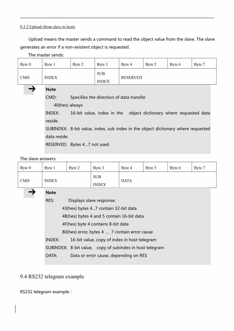
9.3.2 Upload (from slave to host)
Upload means the master sends a command to read the object value from the slave. The slave
generates an error if a non-existent object is requested.
The master sends:
Byte 0 Byte 1 Byte 2 Byte 3 Byte 4 Byte 5 Byte 6 Byte 7
CMD INDEXSUB
INDEXRESERVED
Note
CMD: Specifies the direction of data transfer
40(hex) always
INDEX: 16-bit value, index in the object dictionary where requested data
reside.
SUBINDEX: 8-bit value, index, sub index in the object dictionary where requested
data reside.
RESERVED: Bytes 4…7 not used
The slave answers:
Byte 0 Byte 1 Byte 2 Byte 3 Byte 4 Byte 5 Byte 6 Byte 7
CMD INDEXSUB
INDEXDATA
Note
RES: Displays slave response:
43(hex) bytes 4...7 contain 32-bit data
4B(hex) bytes 4 and 5 contain 16-bit data
4F(hex) byte 4 contains 8-bit data
80(hex) error, bytes 4 … 7 contain error cause
INDEX: 16-bit value, copy of index in host telegram
SUBINDEX: 8-bit value, copy of subindex in host telegram
DATA: Data or error cause, depending on RES
9.4 RS232 telegram example
RS232 telegram example:

ID R/W IndexSub
indexData Checksum Meaning
01 2B 40 60 002F 00 00
0005
Set Controlword = 0x2F, enable the
controller
01 2F 60 60 0006 00 00
000A Set Operation_Mode = 0x06
01 23 7A 60 0050 C3 00
00EF Set Target_position = 50000
01 40 41 60 0000 00 00
001E Read the Statusword
Under each mode, it sends message, All of them use 1 as station number.
Home mode(Controlword F to 1F)
CANOpen Name Value Message(ID=1) Meaning
60400010 Controlword F 01 2B 40 60 00 0F 00 00 00 25
Homing_Speed_Swit
ch and
Homing_Speed_Zero
fault unit is DEC ,
DEC=[(RPM*512*E
ncoder
resolution)/1875]
60600008 Operation_mode 6 01 2F 60 60 00 06 00 00 00 0A
60980008Homing_Metho
d33 01 2F 98 60 00 21 00 00 00 B7
60990120Homing_Speed_
Switch200RPM 01 23 99 60 01 55 55 08 00 30
60990220Homing_Speed_
Zero150RPM 01 23 99 60 02 00 40 06 00 9B
60400010 Controlword 1F 01 2B 40 60 00 1F 00 00 00 15
01 40 41 60 00 00 00 00 00 1ERead state word,C037means home found
Position mode(Controlword Absolute positioning 2F to 3F Relative positioning 4F to 5F,103F Start absolute
positioning)
CANOpen Name Value Message(ID=1) Meaning
60400010 Controlword F 01 2B 40 60 00 0F 0000 00 25
DEC=[(RPM*512*Encoder resolution)/1875]
60600008 Operation_mode 1 01 2F 60 60 00 01 0000 00 0F
607A0020 Target_Position 50000inc 01 23 7A 60 00 50 C300 00 EF
60810020 Profile_Speed 200RPM 01 23 81 60 00 55 5508 00 49
60830020 Profile_Acc 610.352rps/s Default DEC=[(RPS/S* 65536*Encoder 60840020 Profile_Dec 610.352rps/s Default
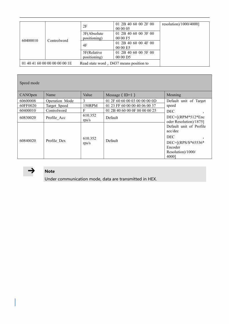
resolution)/1000/4000]
60400010 Controlword
2F 01 2B 40 60 00 2F 0000 00 05
3F(Absolutepositioning)
01 2B 40 60 00 3F 0000 00 F5
4F 01 2B 40 60 00 4F 0000 00 E5
5F(Relativepositioning)
01 2B 40 60 00 5F 0000 00 D5
01 40 41 60 00 00 00 00 00 1E Read state word,D437 means position to
Speed mode
CANOpen Name Value Message(ID=1) Meaning 60600008 Operation_Mode 3 01 2F 60 60 00 03 00 00 00 0D Default unit of Target
speed DEC ,
DEC=[(RPM*512*Encoder Resolution)/1875]
Default unit of Profileacc/dec
DEC ,DEC=[(RPS/S*65536*
EncoderResolution)/1000/
4000]
60FF0020 Target_Speed 150RPM 01 23 FF 60 00 00 40 06 00 37 60400010 Controlword F 01 2B 40 60 00 0F 00 00 00 25
60830020 Profile_Acc 610.352 rps/s Default
60840020 Profile_Dex 610.352 rps/s Default
Note
Under communication mode, data are transmitted in HEX.
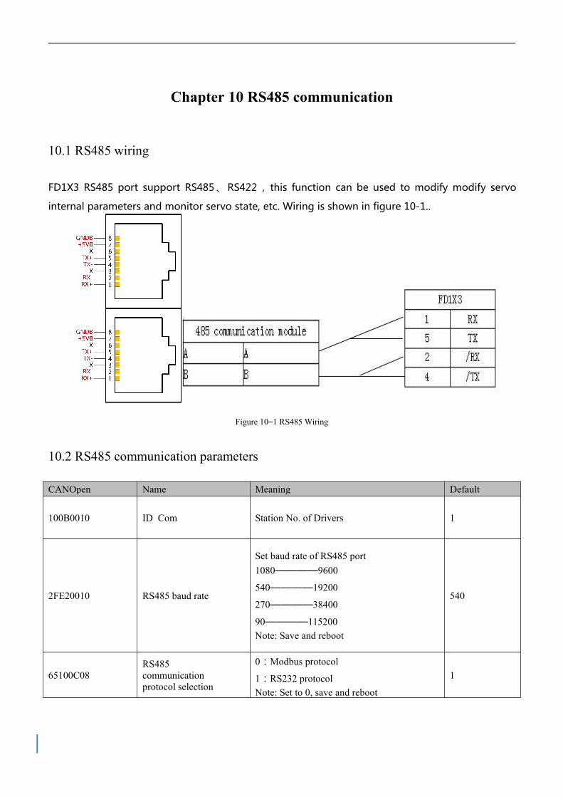
Chapter 10 RS485 communication
10.1 RS485 wiring
FD1X3 RS485 port support RS485 、 RS422 , this function can be used to modify modify servo
internal parameters and monitor servo state, etc. Wiring is shown in figure 10-1..
Figure 10–1 RS485 Wiring
10.2 RS485 communication parameters
CANOpen Name Meaning Default
100B0010 ID_Com Station No. of Drivers 1
2FE20010 RS485 baud rate
Set baud rate of RS485 port 1080————9600
540————19200
270————38400
90————115200 Note: Save and reboot
540
65100C08 RS485 communication
protocol selection
0:Modbus protocol
1:RS232 protocol Note: Set to 0, save and reboot
1
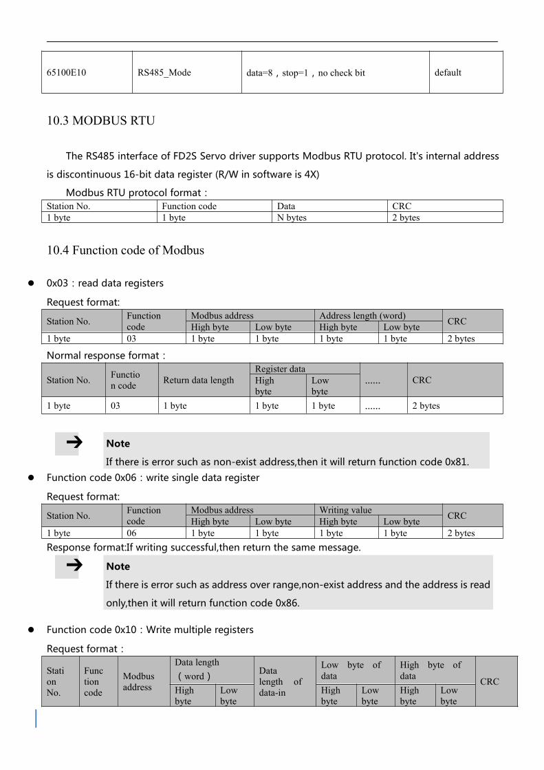
65100E10 RS485_Mode data=8,stop=1,no check bit default
10.3 MODBUS RTU
The RS485 interface of FD2S Servo driver supports Modbus RTU protocol. It's internal address
is discontinuous 16-bit data register (R/W in software is 4X)
Modbus RTU protocol format: Station No. Function code Data CRC 1 byte 1 byte N bytes 2 bytes
10.4 Function code of Modbus
0x03:read data registers
Request format:
Station No. Functioncode
Modbus address Address length (word) CRC
High byte Low byte High byte Low byte 1 byte 03 1 byte 1 byte 1 byte 1 byte 2 bytes
Normal response format:
Station No. Function code Return data length
Register data …… CRC High
byte Low
byte 1 byte 03 1 byte 1 byte 1 byte …… 2 bytes
Note
If there is error such as non-exist address,then it will return function code 0x81.
Function code 0x06:write single data register
Request format:
Station No. Functioncode
Modbus address Writing value CRC
High byte Low byte High byte Low byte 1 byte 06 1 byte 1 byte 1 byte 1 byte 2 bytes
Response format:If writing successful,then return the same message.
Note
If there is error such as address over range,non-exist address and the address is read
only,then it will return function code 0x86.
Function code 0x10:Write multiple registers
Request format:
StationNo.
Functioncode
Modbusaddress
Data length (word) Data
length ofdata-in
Low byte ofdata
High byte ofdata
CRC High
byte Low
byte High
byte Low
byte High
byte Low
byte
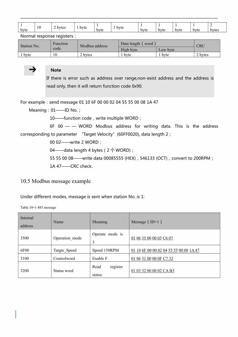
1byte 10 2 bytes 1 byte 1
byte 1 byte 1byte
1byte
1byte
1byte
2bytes
Normal response registers:
Station No. Functioncode Modbus address Data length(word)
CRC High byte Low byte
1 byte 10 2 bytes 1 byte 1 byte 2 bytes
Note
If there is error such as address over range,non-exist address and the address is
read only, then it will return function code 0x90.
For example:send message 01 10 6F 00 00 02 04 55 55 00 08 1A 47
Meaning:01——ID No.;
10——function code,write multiple WORD;
6F 00 — — WORD Modbus address for writing data. This is the address
corresponding to parameter “Target Velocity”(60FF0020), data length 2;
00 02——write 2 WORD;
04——data length 4 bytes(2 个 WORD);
55 55 00 08——write data 00085555 (HEX),546133 (OCT),convert to 200RPM;
1A 47——CRC check.
10.5 Modbus message example
Under different modes, message is sent when station No. is 1:
Table 10–1 485 message
Internal
addressName Meaning Message(ID=1)
3500 Operation_modeOperate mode is
301 06 35 00 00 03 C6 07
6F00 Targte_Speed Speed 150RPM 01 10 6F 00 00 02 04 55 55 00 08 1A 47
3100 Controlword Enable F 01 06 31 00 00 0F C7 32
3200 Status wordRead register
status01 03 32 00 00 02 CAB3

Home(Controlword F to 1F)
Internal
addressName Value Message(ID=1) Meaning
60400010 Controlword F 01 06 31 00 00 0F C7 32
60600008Operation_Mo
de6 01 06 35 00 00 06 06 04
60980008 Home_Method 33 01 06 4D 00 00 21 5E BE
60990120Home_Speed_
Switch200RPM 01 10 50 10 00 02 04 55 55 00 08 0E BA
60990220Home_Speed_
Zero150RPM 01 10 50 20 00 02 04 40 00 00 06 98 76
60400010 Controlword 1F 01 06 31 00 00 1F C6 FE
01 03 32 00 00 02 CAB3 read status word,C037 means home found
Position ( Controlword Absolute positioning 2F to 3F Relative positioning 4F to 5F , 103F Start absolute
positioning)
Internal
addressName Value Message(ID=1) Meaning
60400010 Controlword F 01 06 31 00 00 0F C7 32
60600008Operation_Mo
de1 01 06 35 00 00 01 47 C6
607A0020Target_Positio
n50000inc 01 10 40 00 00 02 04 C3 50 00 00 FE 39
60810020 Profile_Speed 200RPM 01 10 4A 00 00 02 04 55 55 00 08 BC D6
60830020 Profile_Acc 610.352rps/s Default
60840020 Profile_Dec 610.352rps/s Default
60400010 Controlword
2F 01 06 31 00 00 2F C6 EA
3F(Absolute
position)01 06 31 00 00 3F C7 26
4F 01 06 31 00 00 4F C6 C2
5F(Relative
position)01 06 31 00 00 5F C7 0E
01 03 32 00 00 02 CAB3 read state word,D437 means position to
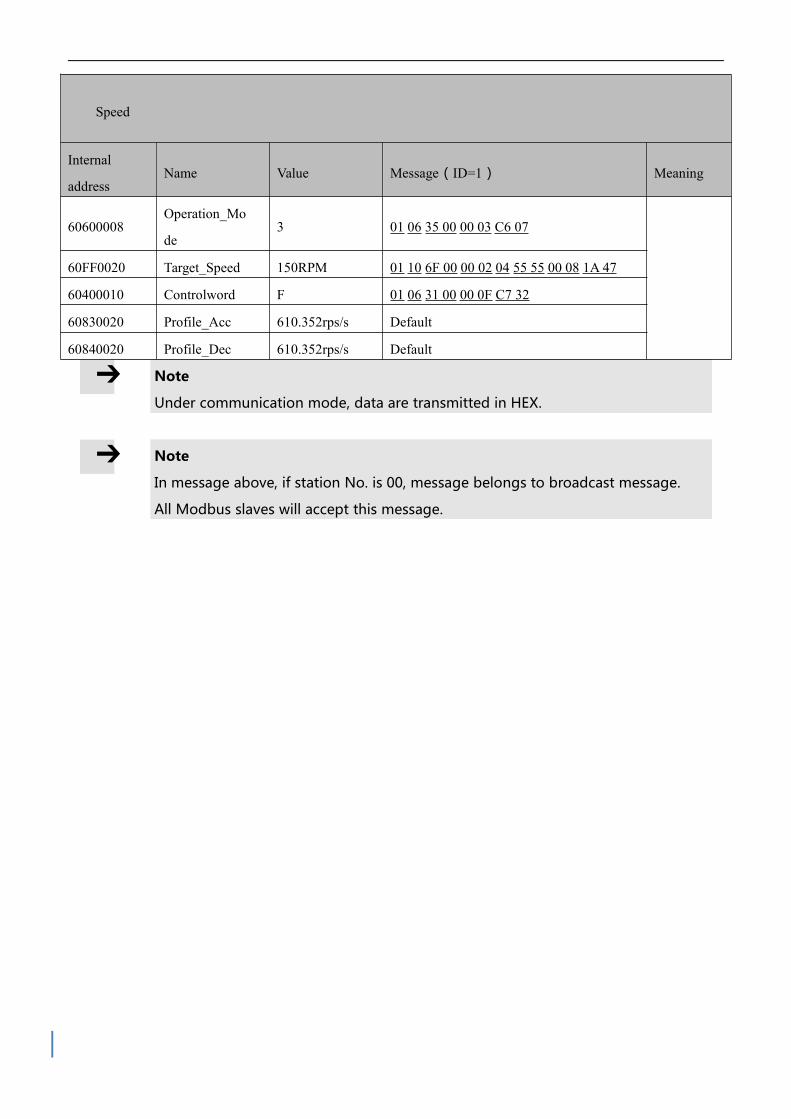
Speed
Internal
addressName Value Message(ID=1) Meaning
60600008Operation_Mo
de3 01 06 35 00 00 03 C6 07
60FF0020 Target_Speed 150RPM 01 10 6F 00 00 02 04 55 55 00 08 1A 47
60400010 Controlword F 01 06 31 00 00 0F C7 32
60830020 Profile_Acc 610.352rps/s Default
60840020 Profile_Dec 610.352rps/s Default
Note
Under communication mode, data are transmitted in HEX.
Note
In message above, if station No. is 00, message belongs to broadcast message.
All Modbus slaves will accept this message.

Chapter 11 CANopen
11.1 CANopen communication protocol
CANopen is one of the most famous and successful open fieldbus standards.It has been
widely recognized and applied a lot in Europe and USA. In 1992,CiA (CANinAutomation) was set
up in Germany,and began to develop application layer protocol CANopen for CAN in automation.
Since then, members of CiA developed a series of CANopen products,and applied in a large
number of applications in the field of machinery manufacturing such as railway, vehicles, ships,
pharmaceutical, food processing etc..Nowadays CANopen protocol has been the most important
industrial fieldbus standard EN-50325-4 in Europe
The FD1X3 series servo supports standard CAN (slave device), strictly follow CANopen2.0A /
B protocol, any host computer which support this protocol can communicate with it. FD1X3
Servo uses of a strictly defined object list, we call it the object dictionary, this object dictionary
design is based on the CANopen international standards, all objects have a clear definition of the
function. Objects said here similar to the memory address, we often say that some objects, such
as speed and position,can be modified by an external controller, some object were modified only
by the drive itself, such as status and error messages.
Table 11–1 Object dictionary example list
Complete CANOpen addressAttribute Meaning
Index Subindex Bits(data length)
0x6040 00 0x10 RW Control word
0x6060 00 0x08 RW Operation mode
0x607A 00 0x20 W Target position
0x6041 00 0x10 MW Status word
The attributes of objects are as follows:
1. RW(read&write):The object can be both read and written;
2. RO(only read):The object can be read only;
3. WO(only write):The object can be written only;
4. M(map):The object can be mapping,similar to indirect addressing;
5. S(save):The object can be stored in Flash-ROM without lost after power failure;

11.2 Hardware Introduction
CAN communication protocol describes a way of transmitting information between devices,
The definition of CAN layer is the same as the open systems interconnection model OSI, each
layer communicates with the same layer in another device, the actual communication takes place
adjacent layers in each device,but the devices only interconnect by the physical media of the
physical layer in the model.CAN standard defines data link layer and physical layer in the mode.
The physical layer of CAN bus is not strictly required, it can use a variety of physical media such as
twisted pair Fibre. The most commonly used is twisted pair signal, sent by differential voltage
transmission (commonly used bus transceiver). The two signal lines are called CAN_H and CAN_L.
The static voltage is approximately 2.5V, then the state is expressed as a logical 1, also called
hidden bit. It represents a logic 0 when CAN_H is higher than the CAN_L, we called it apparent
bit,then the voltage is that CAN_H = 3.5V and CAN_L= 1.5V,apparent bit is in high priority.
The standard CAN interface is shown in figure 11-1.
X1B(OUT)
X1A(IN)
Figure 11–1 FD1X3 CAN interface
Note
This is pin definition of driver, not plugs.
Table 11–2 Pin and function
Pin Symbol Meaning
1 CAN_H CAN_H bus(high dominant )
2 CAN_L CAN_L bus wire (low dominant )
3 CAN_GND CAN ground
4 NC Reserve

5 CAN_SHLD Optional CAN shield
6 GND Optional ground
7 NC Reserve
8 NC Reserve
9 CAN_V+ (NC)not connect
Note
1、All CAN_L and CAN_H of slaves connect directly by using series connection,
not star connection;
2、There must be connected a 120 ohm resistance in start terminal(master) and
end terminal(slave);
3、All FD3 Servo driver don’t need external 24VDC supply for CAN interface;
4 、 Please use the shield wires for communication cable,and make good
grounding(Pin.3 is advised to grounding when communication is in long distance
and high baudrate);
5、The max. distance at different baudrate are shown in following table.
Table 11–3 The max. distance at different baudrate are shown in following table (Theory)
Communication speed(bit/s) Communication distance(M)
1M 25
500K 100
250K 250
125K 500
50K 600
11.3 Software introduction
11.3.1 EDS introduction
EDS(Electronic Data Sheet)file is an identification documents or similar code of slave device,to
identify what kind of slave device is(Like 401,402 and 403,or which device type of 402).This file
includes all information of slaves,such as manufacturer,sequence No.,software version,supportable
baudrate, mappable OD and attributes of each OD and so on,similar to the GSD file for
Profibus.Therefore,we need to import the EDS file of slave into the software of master before we
configure the hardware.
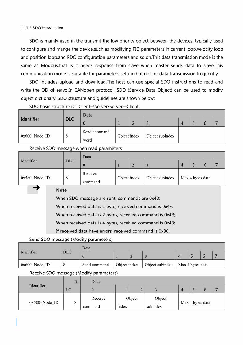
11.3.2 SDO introduction
SDO is mainly used in the transmit the low priority object between the devices, typically used
to configure and mange the device,such as modifying PID parameters in current loop,velocity loop
and position loop,and PDO configuration parameters and so on.This data transmission mode is the
same as Modbus,that is it needs response from slave when master sends data to slave.This
communication mode is suitable for parameters setting,but not for data transmission frequently.
SDO includes upload and download.The host can use special SDO instructions to read and
write the OD of servo.In CANopen protocol, SDO (Service Data Object) can be used to modify
object dictionary. SDO structure and guidelines are shown below:
SDO basic structure is:Client→Server/Server→Client
Identifier DLCData
0 1 2 3 4 5 6 7
0x600+Node_ID 8Send command
wordObject index Object subindex
Receive SDO message when read parameters
Identifier DLCData
0 1 2 3 4 5 6 7
0x580+Node_ID 8Receive
commandObject index Object subindex Max 4 bytes data
Note
When SDO message are sent, commands are 0x40;
When received data is 1 byte, received command is 0x4F;
When received data is 2 bytes, received command is 0x4B;
When received data is 4 bytes, received command is 0x43;
If received data have errors, received command is 0x80.
Send SDO message (Modify parameters)
Identifier DLCData
0 1 2 3 4 5 6 7
0x600+Node_ID 8 Send command Object index Object subindex Max 4 bytes data
Receive SDO message (Modify parameters)
IdentifierD
LC
Data
0 1 2 3 4 5 6 7
0x580+Node_ID 8Receive
command
Object
index
Object
subindexMax 4 bytes data

Note
If sent data ready is 1 byte, command is 0x2F;
If sent data ready is 2 bytes, command is 0x2B;
If sent data ready is 4 bytes, command is 0x23;
If SDO message is sent successfully, receive command is 0x60;
If SDO message is not sent successfully, receive command is
0x80.
11.3.3 PDO introduction
PDO can transport 8 bytes of data at one time,and no other protocol preset(Mean the content
of the data are preset),it is mainly used to transmit data in high frequency.PDO uses brand new
mode for data exchange,it needs to define the data receiving and sending area before the
transmission between two devices,then the data will transmit to the receiving area of devices
directly when exchanging data.It greatly increase the efficiency and utilization of the bus
communication.
11.3.3.1 PDO COB-ID introduction
COB-ID is a unique way of CANopen communication protocol,it is the short name of
Communication Object Identifier. These COB-ID defines the respective transmission levels for PDO,
These transport level, the controller and servo will be able to be configured the same transmission
level and the transmission content in the respective software.Then both sides know the contents of
data to be transferred, there is no need to wait for the reply to check whether the data transmission
is successful or not when transferring data.
The default ID allocation table is based on the CAN-ID(11 bits) defined in CANopen 2.0A(The
COB-ID of CANopen 2.0B protocol is 27 bits),include function code(4 bits) and Node-ID(7 bits) as
shown in diagram 11-2.
Figure 11–2 Default ID allocation table
Note
Node-ID —— Servo station No.,Node-ID range is 1~127;

Function Code — — The function code for data transmission define the
transmission level of PDO,SDO and management message.The smaller the
function code,the higher the priority.
Table 11–4 The allocation table for CAN identifiers in master/slave connection set predefined by CANopen
Object COB-ID
NMT Module Control 000H
SYNC 080H
TIME SSTAMP 100H
Object COB-ID
Emergency 081H-0FFH
PDO1(Send) 181H-1FFH
PDO1(Receive) 201H-27FH
PDO2(Send) 281H-2FFH
PDO2(Receive) 301H-37FH
PDO3(Send) 381H-3FFH
PDO3(Receive) 401H-47FH
PDO4(Send) 481H-4FFH
PDO4(Receive) 501H-57FH
SDO(Send/Server) 581H-5FFH
SDO(Receive/Client) 601H-67FH
NMT Error Control 701H-77FH
Note
1、The smaller the COB-ID,the higher the priority;
2、The function codes of COB-ID in every level are fixed;
3 、 COB-ID of 00H, 80H, 100H, 701H-77FH, 081H-0FFH are
system management format;
11.3.3.2 COB-ID
Send PDO of servo means servo sends out data,and these data are received by PLC.The
function codes of send PDO (COB-ID) are as follow:
1、0x180+Station No. of Servo
2、0x280+Station No. of Servo
3、0x380+Station No. of Servo
4、0x480+Station No. of Servo

Receive PDO of servo means servo receive data,and these data are sent by PLC.The function
codes of receive PDO(COB-ID) are as follows:
1、0x200+Station No. of Servo
2、0x300+Station No. of Servo
3、0x400+Station No. of Servo
4、0x500+Station No. of Servo
Note
FD2S Servo is designed according to the standard of CANopen 2.0A
protocol,and it also supports CANopen 2.0B protocol.Therefore,if 8 PDOs are
not enough,users can define new PDO,for example,set 0x43FH as the
communication PDO of Station No.1,but it needs the controllers and servo
define PDO by the same rule.
1.3.3.3 PDO transmission types
PDO support two transmission mode:
SYNC——Transmission is triggered by the synchronization message(Transmission type:0-240)
In this transmission mode, controller must have the ability to send synchronous messages(The
message is sent periodically at a maximum frequency of 1KHz),and servo will send after receiving
the synchronous message.
Acyclic:Pre-triggered by remote frame,or by specific event of objects specified by the
equipment sub-protocol.In this mode,servo will send out data as soon as receiving the data of
synchronous message PDO.
Cyclic:Triggered after sending 1 to 240 SYNC messages.In this mode,servo will send out data in
PDO after receiving n SYNC messages.
ASYNC (Transmission type:254/255)
Slave sends out message automatically as soon as the data change,and it can define an interval
time between two messages which can avoid the one in high priority always sending message.(The
smaller number of PDO,the higher its priority)
For FD1X3 series servo drivers, they supports 256 transmission methods. Users only need to
use supporting method of transmission methods (controller) to choose driver's transmission
methods.
Note
Each PDO can define an inhibit time,that is the minimum
interval time between two continuous PDO transmission.It is

used to avoid the PDO in higher priority always occupying the
communication.The inhibit time is 16bit unsigned integer,its unit
is 100us.
11.3.3.3 Protection mode (Supervision)
Supervision type is to choose which way master uses to check slave during operation,and
check whether slave is error or not and handle the error!
1、Heartbeat message
Heartbeat message:Slave send message to master cyclically during supervision time.If master
hasn’t received the message from slave after heartbeat time,then master will consider slave as
error!
Message format
(0x700+NodeID)+Status
Status:
0:Start 4:Stop 5:Run 127:Pre-operational
2、Node guarding
Slave send message to master cyclically during supervision time.If master hasn’t received the
message from slave after supervision time,then master will consider slave as error !
The format of master request message——(0x700+NodeID)(No data in this message)
Format of slave response message——(0x700+NodeID)+Status
The bit7 of the data is triggered bit.This bit will alternately set to 0 or 1 in the response
message.It will be set to 0 at the first request of node guarding.The bit0 ~ bit6 indicate the status of
node.
Status: 0:Initialization 1:No connection 2.Connection 3:Operational 4:Stop 5:Run
127:Pre-operational
Normally standard CAN slave only one protection mode,but FD2S Servo can support both.
11.3.3.4 Boot-up process
During the process of internet initialization, CANopen support extending boot-up and support
min boot-up process. The boot-up process is shown in following figure 11-3:

Figure 11–3 Boot-up process
Table 11–5 CANopen Internet process
Code Meaning
a NMT
b Node Guard
c SDO
d Emergency
e PDO
F Boot-up
Management message format
COB-ID DLC Byte0 Byte1
0x000 02 CS Station No.
When Node-ID is 0, all NMT slave devices are addressed. CS is command, value table is shown
in table 11-6.
Table 11–6 CS Value table
Command NMT service
0x01 Open node, start PDO transmission
0x02 Close node, end PDO transmission
0x80 Come to pre-operation status
0x81 Reset node
0x82 Reset communication
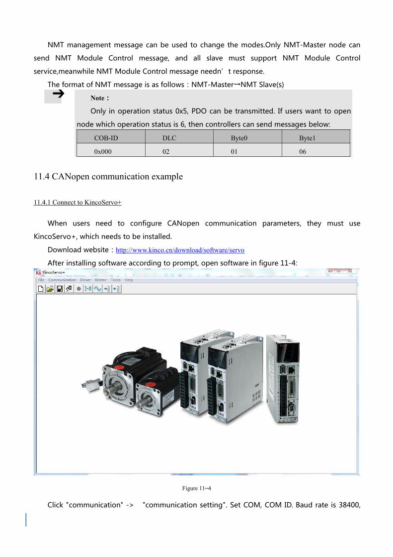
NMT management message can be used to change the modes.Only NMT-Master node can
send NMT Module Control message, and all slave must support NMT Module Control
service,meanwhile NMT Module Control message needn’t response.
The format of NMT message is as follows:NMT-Master→NMT Slave(s)
Note:
Only in operation status 0x5, PDO can be transmitted. If users want to open
node which operation status is 6, then controllers can send messages below:
COB-ID DLC Byte0 Byte1
0x000 02 01 06
11.4 CANopen communication example
11.4.1 Connect to KincoServo+
When users need to configure CANopen communication parameters, they must use
KincoServo+, which needs to be installed.
Download website:http://www.kinco.cn/download/software/servo
After installing software according to prompt, open software in figure 11-4:
Figure 11–4
Click "communication" -> "communication setting". Set COM, COM ID. Baud rate is 38400,

COM ID default is 1. If users don't know COM ID, they can use broadcast address 127. After
configuration, click "OEPN".
Figure 11–5
Note
As driver follow the logic - IO control prior to
communication control, so users need to cancel IO function
when apply CANopen. If driver is enable or operation mode
switch, communication cannot control servo control word,
operation mode, etc.
Note
Use DIP switch to configure driver ID. Configuration method
is shown in outside printing of driver.
11.4.2 Configure CANopen parameters
Note
For CANopen parameters, please check driver → ECAN
configuration→Others
The maters which have function of network management can initialize slave parameters by
sending SDO. Commonly, SYNC ID, node protection time, node protection time factor, node
protection station No., emergency message station No., heartbeat message production time
don’t need to be set by users.

Figure 11–6 KincoServo CANopen configuration
Table 11–7 CANopen parameters
CANopen
address
Name Description Value
10050020 Sync_ID Active when communication type is sync mode(1-240). No setting
in async mode.
80
100C0010 Guard_Time Nodes protect masters, it can monitor current state of every node.
Masters (node protection time as period) send remote frame to
check slave node state (Default COBID is 0x700+ID, message
without content).Nodes need to response in a time. Otherwise,
master nodes regard slave nodes off-line. Driver will have alarms.
1000
100D0008 Life_Time_Fac
tor
3
100E0020 Node_Guard_I
D
700+driver ID
10140020 Emergency_Me
ss_ID
80+driver ID
10170010 Producer_Heart
beat_Time
Slave nodes cyclically send master nodes. If master nodes don't
receive message, master nodes will regard slave nodes off-line
within a time.
2F810008 CAN_Baudrate CAN baudrate setting
100:1M
50:500k
25:250k
12:125k
50
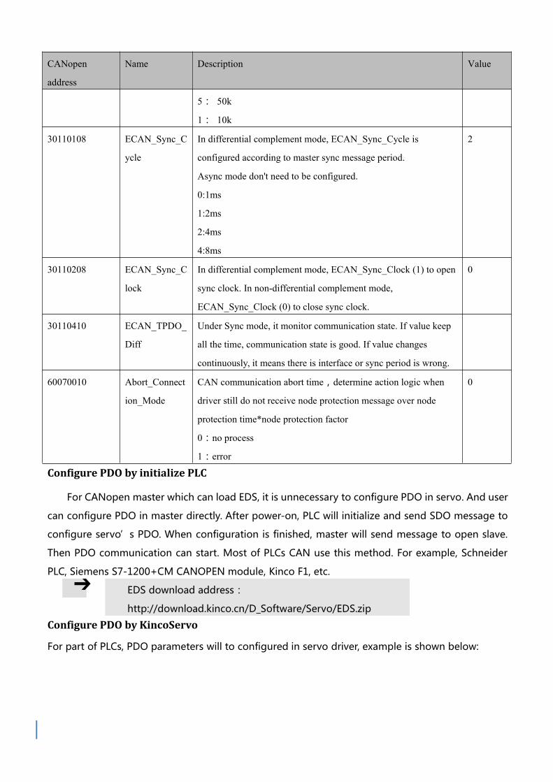
CANopen
address
Name Description Value
5: 50k
1: 10k
30110108 ECAN_Sync_C
ycle
In differential complement mode, ECAN_Sync_Cycle is
configured according to master sync message period.
Async mode don't need to be configured.
0:1ms
1:2ms
2:4ms
4:8ms
2
30110208 ECAN_Sync_C
lock
In differential complement mode, ECAN_Sync_Clock (1) to open
sync clock. In non-differential complement mode,
ECAN_Sync_Clock (0) to close sync clock.
0
30110410 ECAN_TPDO_
Diff
Under Sync mode, it monitor communication state. If value keep
all the time, communication state is good. If value changes
continuously, it means there is interface or sync period is wrong.
60070010 Abort_Connect
ion_Mode
CAN communication abort time,determine action logic when
driver still do not receive node protection message over node
protection time*node protection factor
0:no process
1:error
0
Configure PDO by initialize PLC
For CANopen master which can load EDS, it is unnecessary to configure PDO in servo. And user
can configure PDO in master directly. After power-on, PLC will initialize and send SDO message to
configure servo’s PDO. When configuration is finished, master will send message to open slave.
Then PDO communication can start. Most of PLCs CAN use this method. For example, Schneider
PLC, Siemens S7-1200+CM CANOPEN module, Kinco F1, etc.
EDS download address:
http://download.kinco.cn/D_Software/Servo/EDS.zip
Configure PDO by KincoServo
For part of PLCs, PDO parameters will to configured in servo driver, example is shown below:
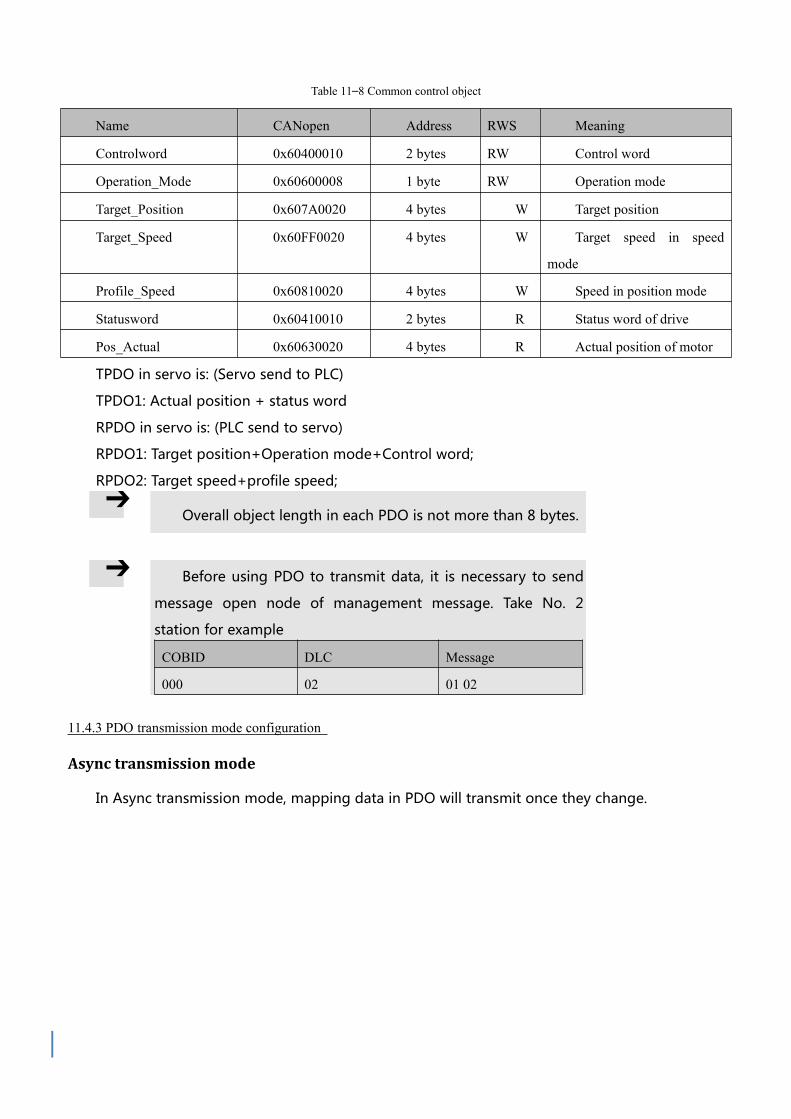
Table 11–8 Common control object
Name CANopen Address RWS Meaning
Controlword 0x60400010 2 bytes RW Control word
Operation_Mode 0x60600008 1 byte RW Operation mode
Target_Position 0x607A0020 4 bytes W Target position
Target_Speed 0x60FF0020 4 bytes W Target speed in speed
mode
Profile_Speed 0x60810020 4 bytes W Speed in position mode
Statusword 0x60410010 2 bytes R Status word of drive
Pos_Actual 0x60630020 4 bytes R Actual position of motor
TPDO in servo is: (Servo send to PLC)
TPDO1: Actual position + status word
RPDO in servo is: (PLC send to servo)
RPDO1: Target position+Operation mode+Control word;
RPDO2: Target speed+profile speed;
Overall object length in each PDO is not more than 8 bytes.
Before using PDO to transmit data, it is necessary to send
message open node of management message. Take No. 2
station for example
COBID DLC Message
000 02 01 02
11.4.3 PDO transmission mode configuration
Async transmission mode
In Async transmission mode, mapping data in PDO will transmit once they change.

Figure 11–7TPDO configuration in Async mode
Table 11–9 TPDO configuration in Async transmission mode
Name Meaning
TPDO1 mapping
group
Paired object No. in this PDO. In TPDO1, actual position and status word are configured.
Map 1-8 Configure servo CANopen control object
TPDO1 station No. 180+driver ID (TPDO2 station No.:280+driver ID)
TPDO1
transmission type
254 or 255, Async transmission mode
TPDO1 prohibited
time
Unit is ms, in case that frequency of message sent by servo is too high so as to block network,
it is indeed configured in multi-shaft async transmission mode
Note
In TPDO1, overall length of paired object actual position and status word is
4+2=6
Default of RPDO transmission mode is 254. Users do not need to set. After
receiving data, it is immediate effect.
Event time timing reported function
In sync transmission mode, except for (transmission once change), if driver upload data to
controller periodically , event time can be configured.

Figure 11–8 Event time timing reported in async mode
Table 11–10 Event time timing reported in async mode
Name Meaning
TPDO1 mapping
group
Paired object No. in this PDO. In TPDO1, actual position and status word are configured.
Map 1-8 Configure servo CANopen control object
TPDO1 station No. 180+driver ID (TPDO2 station No.:280+driver ID)
TPDO1
transmission type
254 or 255,Async transmission mode
TPDO1 prohibited
time
254 or 255, Async transmission mode
TPDO1 event time Period (Driver send PDO to controller), unit is ms
Note: In TPDO1, overall length of paired object actual position and status word is 4+2=6
Sync transmission mode
When CANopen communication configuration is sync transmission mode, mapping data in
TPDO will be upload after driver receive sync message.
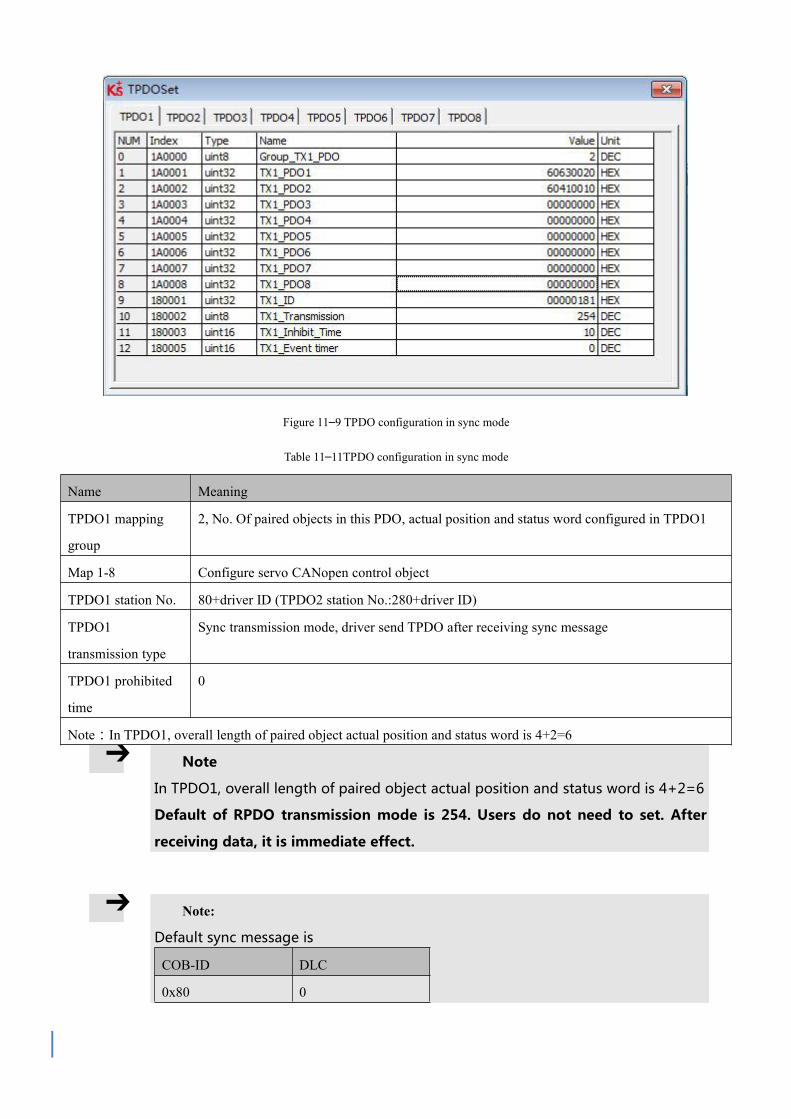
Figure 11–9 TPDO configuration in sync mode
Table 11–11TPDO configuration in sync mode
Name Meaning
TPDO1 mapping
group
2, No. Of paired objects in this PDO, actual position and status word configured in TPDO1
Map 1-8 Configure servo CANopen control object
TPDO1 station No. 80+driver ID (TPDO2 station No.:280+driver ID)
TPDO1
transmission type
Sync transmission mode, driver send TPDO after receiving sync message
TPDO1 prohibited
time
0
Note:In TPDO1, overall length of paired object actual position and status word is 4+2=6
Note
In TPDO1, overall length of paired object actual position and status word is 4+2=6
Default of RPDO transmission mode is 254. Users do not need to set. After
receiving data, it is immediate effect.
Note:
Default sync message is
COB-ID DLC
0x80 0

Differential complement mode based on CANopen
In differential complement mode based on CANopen, operation mode (0x60600008) is 7.
Diagram 11–12 Differential complement operation mode is 7
Name CANopen address Length RWS Meaning
Operation_Mode 60600008 1 byte RW Operation mode
Figure 11–10 Parameters in differential complement mode
Table 11–13 Parameters in differential complement mode
CANopen
address
Name Meaning Default
30110108 ECAN_Sync_Cyc
le
In differential complement mode,
ECAN_Sync_Cycle is configured
according to master sync message period.
Async mode don't need to be configured.
2

0: 1ms
1: 2ms
2: 4ms
4: 8ms
30110208 ECAN_Sync_Clo
ck
In differential complement mode,
ECAN_Sync_Clock (1) to open sync
clock. In non-differential complement
mode, ECAN_Sync_Clock (0) to close
sync clock.
0
CAN communication interruption alarm function
For CAN communication interruption alarm function, parameters below need to be configured
Table 11–14 Communication interruption alarm function configuration
CANopen address Name Meaning Default
100C0010 Guard_Time Nodes protect masters, it can monitor current state
of every node. Masters (node protection time as
period) send remote frame to check slave node state
(Default COBID is 0x700+ID, message without
content).Nodes need to response in a time.
Otherwise, master nodes regard slave nodes off-line.
Driver will have alarms.
1000
100D0008 Life_Time_Factor 3
100E0020 Node_Guarding_ID 700+driver ID
10140020 Emergency_Mess_ID 80+driver station No.
60070010 Abort_Connection_M
ode
CAN communication abort time,determine action
logic when driver still do not receive node
protection message over node protection time*node
protection factor
0:no process
1:Error
0
11.4.4 CANopen send message example
Node protection message and heartbeat message
CANopen node will transmit heartbeat message at a fixed frequency, which is used to inform

controller that communication connection is normal. Format of message is simple. COB-ID is
0x700+Node_ID
Figure 11–11 Node message and heartbeat message
In diagram above, ID is 706, which is the heartbeat of 06 node and state is 0x7F. It is
Pre-Operational state (After node initialization finishes, it comes to Pre-Operational state). By
checking time, time interval between each heartbeat message is about 1s.
NMT management message
NMT is management message, used to achieve some management operations such as node open,
enter-in Operational state, etc. Format of NMT message is simple and ID is 000. Data consists of
one byte command and one byte node number (0 is broadcast)
Figure 11–12 Open node
The second message can make 06 node enter in Operational state. After running, node state in
node heartbeat message becomes Operational state. Under this state, PDO start to transmit.
Figure 11–13 Close node

Send stop remote node command and go to Stopped state. Obviously, heartbeat still exist and only
node doesn’t work.
Figure 11–14 Reset node
This is reset node command, which is used to make node reset. After reset, it enters in
Initializing node (for 0x00 in heartbeat message). After initialization is finished, it enters in
Pre-Operational state (for 0x7F in heartbeat message).
Send and receive SDO
SDO is mainly used to visit node’s OD. Node in CANopen at least need to support SDO_Server.
OD is data organization of CANopen node, which includes each parameter and data of CANopen
node such as sending frequency of heartbeat frequency, system start times, node communication
parameters and etc. So SDO is used to set each running parameter of CANopen node.
Figure 11–15 Send SDO message and read data
In diagram 11-17, No.1 message 0606:40 17 10 00 00 00 00 00 is a SDO_Read message, which
can tell node to read OD’s index, subindex and also data length. Then node will send
corresponding data (8 bytes message behind). The first byte is command. The second and third
byte are OD’s main address. The fourth byte is OD’s subaddress. The last four bytes are data. In
diagram above, master send data command to read OD (in 1017:00). This position stores heartbeat
frequency and result of read is 0x03EB (1000ms).

Figure 11–16 Send SDO message and modify data
No.9 message is SDO_Write, which writes data in OD (1017:00). It is also to modify heartbeat
frequency. After receiving response, heartbeat frequency changes.
Send and receive data message in different mode (Station No. is 1)
Homing(Controlword F to 1F)
CANopen Name Value Send and reply message(ID=1)Meani
ng
60400010 Controlword F601 2B 40 60 00 0F 00
581 60 40 60 00 0F 00
60600008 Operation_Mode 6601 2F 60 60 00 06 00
581 60 60 60 00 06 00
60980008 Homing_Method 33601 2F 98 60 00 21 00
581 60 98 60 00 21 00
60990120 Homing_Speed_Switch 200RPM601 23 99 60 01 55 55 08 00
581 60 99 60 01 55 55 08 00
60990220 Homing_Speed_Zero 150RPM601 23 99 60 02 00 40 06 00
581 60 99 60 02 00 40 06 00
60400010 Controlword 1F601 2B 40 60 00 1F 00
581 60 40 60 00 1F 00
601 40 41 60 00 00 00 00 00 read status word,C037means home found

Position ( Controlword Absolute positioning 2F to 3F Relative positioning 4F to 5F , 103F Start absolute
positioning)
CANopen Name Value Message(ID=1)Meani
ng
60400010 Controlword F601 2B 40 60 00 0F 00
581 60 40 60 00 0F 00
60600008Operation_Mod
e1
601 2F 60 60 00 01 00
581 60 60 60 00 01 00
607A0020 Target_Position 50000inc601 23 7A 60 00 50 C3 00 00
581 60 7A 60 00 50 C3 00 00
60810020 Profile_Speed 200RPM601 23 81 60 00 55 55 08 00
581 60 81 60 00 55 55 08 00
60830020 Profile_Acc 610.352rps/s Default
60840020 Profile_Dcc 610.352rps/s Default
60400010 Controlword
2F601 2B 40 60 00 2F 00
581 60 40 60 00 2F 00
3F(absolute
positioning)
601 2B 40 60 00 3F 00
581 60 40 60 00 3F 00
4F601 2B 40 60 00 4F 00
581 60 40 60 00 4F 00
5F(relative
positioning)
601 2B 40 60 00 5F 00
581 60 40 60 00 5F 00
601 40 41 60 00 00 00 00 00 read status word,D437means position found
Speed
CANopen Name Value Message(ID=1)Meani
ng
60600008Operation_Mo
de3
601 2F 60 60 00 03 00
581 60 60 60 00 03 00
60FF0020 Target_Speed 150RPM601 23 FF 60 00 00 40 06 00
581 60 FF 60 00 00 40 06 00

60400010 Controlword F601 2B 40 60 00 0F 00
581 60 40 60 00 0F 00
60830020 Profile_Acc Default 610.352rps/s Default
60840020 Profile_Dcc Default 610.352rps/s Default
Note:PDO Under communication mode, data are transmitted, sent and received in HEX.
SDO Send and received SDO
PDO is used to send (TPDO) and receive (RPDO) data. There are different triggering methods
such as sync transmission and async transmission. PDO’s data content is defined in OD by
mapping. One node can have multiple PDO channels. PDO’s communication parameters can be
modified by which SDO visits OD.
Figure 11–17 Content in TPDO1 mapping group
In TPDO1, it map 3 objects, actual position, actual current and effective work mode in turn.
Then from cutting PDO message, actual position is 0xFaE84270.

Figure 11–18 Cutting PDO message content

Appendix 1 Configure third-party motors
Name Parameters Meaning
Motor pole pairs Required Check motor drawing
Motor max current Required Motor max current is 2.5 times of rated current
Phase inductance Required Check motor drawing
Phase resistance Required Check motor drawing
Back EMF factor of
motor
Required Check motor drawing
Torque coefficient
of motor
Required Check motor drawing
Rotor inertia Required Check motor drawing
Encoder resolution Required Encoder single-turn pulse×4
Brake duty cycle Refer to notes 90%
Brake delay Refer to notes 150ms
Motor Number Refer to notes Type is XX
Feedback type Refer to notes 10
Feedback period Refer to notes Encoder resolution
Commutation mode Refer to notes Mode 0 or mode 10
Commutation
current
Refer to notes 0.75 times of motor rated current
Commutation time Refer to notes Default 2000ms
Current setting for
excess temperature
protection of motor
Refer to notes Rated current
Timing setting for
excess temperature
protection of motor
Refer to notes 60S
Motor current Refer to notes Default 2000Hz

control loop
bandwidth
Note
After finishing left table, use software and find motor settings.
Then write in information and save motor parameters and
initialize control parameters. Reboot driver.
If there is no alarm of motor after power-on, users can try other
control modes.
If there is alarms, please refer to driver menu and check step by
step.
If there is no alarm but motor doesn't run, please check if
resolution is correct. Then check if UVW wire is wrong because
standards of every company is different. And maybe users need to
make UV wire reverse. At last, please check if commutation mode
is correct.
The configuration against encoder feedback type is incremental
5V differential signal including A,/A,B,/B,Z/Z three road encoder
signal which is encoder signal supported by standards.

Appendix 2 Formula
Motor in card walking, suitable for motor + gearbox + wheel
Formula:T*n=μ*m*g*d/2
Wheel diameter d m
Reduction speed of gearbox n 1:n
Torque of motor T Nm, kgm²/s²
Load ability of car m kg
Coefficient of friction μ No unit
Gravitational acceleration g m/s²
Under the pulse mode, relationship between No. of pulse and mechanical displacement
Formula:N*A/B=s*n*r/P
Gear ratio numerator A No unit
Gear ratio denominator B No unit
Screw pitch P mm
Motor single-turn pulse r No unit
Gear ratio 1:n No unit
Mechanical displacement s mm
Pulse N No unit
Relationship between rotation speed and line velocity
Formula:n=v÷r÷π
Rotation speed n rpm
Line velocity v mm/s
Radius r mm
NameEngineerin
g unitInternal unit Conversion
Velocity rpm DEC DEC=[(RPM*512*encoder resolution)/1875]
Acceleration r/s2 DEC DEC=[(RPS/S*65536*encoder resolution)/4000000]
Current A DEC 1Arms=(2048/(driver peak current )Ipeak/1.414)dec

For example, engineering unit of speed is rpm and internal unit is dec. The relationship is:
1RPM=2730dec (Encoder resolution 10000)! It is assumed that speed is 10rpm, user need to write
27300dec (6AA4 in HEX) when use communication to control.

Appendix 3 Use of brake resistor
PowerSize
W±1 H±1 L1±2 L2±2 L3±2 D±0.5 A±10
100W 40 20 110 140 125 5.2 300
250W 60 30 130 165 150 5.2 300
Driver typeBrake resistor
type
Brake resistor
resistance[Ω]
Brake resistor
power[W]
Brake resistor voltage
resistant [VDC]
(Minimum)
FD123 T-10R-100 10 100 500
FD133 T-10R-250 10 250 500
Use of brake resistor
Address Data type Modbus address RWS Unit Meaning
65100810 Unsigned16 0x6810 RW VChopping voltage point,default
70V
60F70110 Unsigned16 0x6010 RW Ω Brake resistor resistance
60F70210 Unsigned16 0x6020 RW W Brake resistor power

Appendix 4 General load inertia calculation
Drum
inertia
Eccen
tric
circul
ar
plate
inertia
/Drum
inertia
(Rotat
ion
center
is
shifte
d)
Rotati
ng
prism
inertia

Rectili
near
motio
n
object
inertia
Object
inertia
when
it is
lifted
by
pulley
Object
inertia
when
it is
trans
mitted
by
rack
or
gear
Inertia
with
counte
rweig
ht
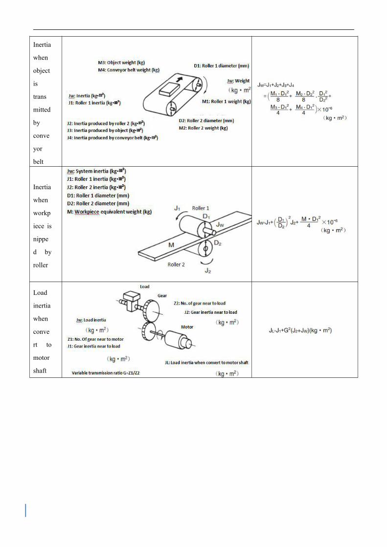
Inertia
when
object
is
trans
mitted
by
conve
yor
belt
Inertia
when
workp
iece is
nippe
d by
roller
Load
inertia
when
conve
rt to
motor
shaft