Embed Size (px)
Citation preview

Chapter 6
© 2012 Azukuzawa and Yamamoto, licensee InTech. This is an open access chapter distributed under the terms of the Creative Commons Attribution License (http://creativecommons.org/licenses/by/3.0), which permits unrestricted use, distribution, and reproduction in any medium, provided the original work is properly cited.
Feasibility Study of a Passive Magnetic Bearing Using the Ring Shaped Permanent Magnets
Teruo Azukuzawa and Shigehiro Yamamoto
Additional information is available at the end of the chapter
http://dx.doi.org/10.5772/51347
1. Introduction
Magnetic bearings can suspend rotating bodies without any mechanical contact. They have
advantages such as being free of dust, noise, vibration and maintenance. Some magnetic
bearings are already in commercial use in specific apparatuses such as high vacuum pumps
or contamination free applications [1]. However, the high cost of the control apparatus for
five degrees of freedom of the rotor prevents their wide application at present. It is thus
necessary to develop a low-cost magnetic bearing system.
The authors have previously reported on the characteristics of the magnetic force acting between
a couple of permanent magnets [2]. A magnetic top, consisting of a couple of ring-shaped
permanent magnets, can be levitated without any control while maintaining rotation by itself.
This fact suggests that the magnetic top may be a potential candidate for a passive magnetic
suspension system. Several efforts have been made to explain the levitation mechanism of the
magnetic top. San Miguel proposed noble analytical method with complex formulas showing
that a magnetic top can maintain levitation if it rotates with slight precession [3].
In this chapter, an intuitive and easy analytical method based on the equivalent coil currents
model for a ring-shaped permanent magnet is proposed.
A quasi-three-dimensional analysis, in which the three-dimensional shapes and layout of
the ring-shaped permanent magnets are considered to estimate the magnetic forces acting
on the levitating permanent magnet, is proposed. The principle of levitation of the magnetic
top and the dimensions of the permanent magnets to realise levitation are discussed using
the two-dimensional equations of motion for the magnetic top.
Furthermore, simulations based on the three-dimensional equations of motion are
performed to investigate the dynamic behaviour of the magnetic top. The simulated results
well predict the dynamic behaviour observed in the experiments. The simulations based on

Performance Evaluation of Bearings 136
the three-dimensional analysis are used to investigate the effects of the key parameters on
the levitating characteristics, such as the sizes of both the ground and rotating permanent magnets, mass of the levitating top, tilt angle of the levitating top, rotation speed and initial
position related to the restoring centre.
The ability and feasibility of the magnetic top as a magnetic bearing are also discussed.
2. Analytical methods
The magnetic top is composed of a couple of ring-shaped permanent magnets magnetised in the
axial direction, as shown in Figure 1. The magnetic top, equipped with a smaller ring-shaped
permanent magnet (a rotor magnet), can be levitated in the magnetic field generated by the
larger ring-shaped permanent magnet (a stator magnet) situated at its base, if it can maintain its
rotation within a certain speed range. The levitating height is determined by the shapes and
magneto-motive forces of the permanent magnets. The authors propose two types of analytical
methods: (1) a quasi-three-dimensional analysis to investigate the principle of levitation and the
design parameters of the permanent magnets and (2) a three-dimensional dynamic analysis to
simulate the behaviour of the levitating magnetic top. The ring-shaped permanent magnet is
approximated to the equivalent coil currents model in both the analytical methods.
2.1. The equivalent coil currents approximation
In the equivalent coil currents approximation, a ring-shaped permanent magnet, magnetised
in the axial direction, is assumed to exist by the set of circular coil currents located at the
outer and inner side surfaces of the ring-shaped permanent magnet [4]. The directions of
currents in the outer and inner equivalent coils are inversed with each other, describing the
axial magnetization of the permanent magnet, as shown in Figure 2. The magnitude of these
equivalent side currents is determined so as to coincide with the measured magnetic field
density at the pole surface of the permanent magnet in relation to the number of the
assumed equivalent coils.
Figure 3 shows the analytical model based on the equivalent side currents model. The outer
and inner diameters and the height of the ring-shaped permanent magnets are represented as
dso, dsi and hs for the stator magnet and dro, dri and hr for the rotor magnet, respectively. The
angle θ is the tilt angle of the rotor magnet. The origin is set at the centre of the stator magnet.
The stator magnet is located in the horizontal x–y plane and z-axis is set as the vertical
direction along the axis of the stator magnet. The numbers of the equivalent side currents in
both the rotor and stator magnets, indicated as one and three in Figure 3, are decided
considering both the accuracy of the calculated results and the required time for computation.
2.2. Magnetic force acting on the rotor magnet
Magnetic force acting on a magnetic top can be estimated by the interaction between the
magnetic field generated by the stator magnet and the equivalent coil currents of the rotor

Feasibility Study of a Passive Magnetic Bearing Using the Ring Shaped Permanent Magnets 137
magnet. In an analysis based on the equivalent side currents approximation, magnetic forces
acting on the magnetic top can be estimated by integrating magnetic forces acting between
equivalent coil currents in the rotor and stator magnets.
The magnetic force df [N] acting between two current elements dl1 [m] and dl2 [m] and
two transporting currents I1 [A] and I2 [A] is estimated by the following Biot-Savart’s
equation:
71 2 1 22
10 sinI I dl dl
dfr
(1)
where r [m] is the distance between the two current elements and φ [rad] is the angle
between the directions of the current elements.
Then, the magnetic force f [N] acting between two ring-shaped coil currents is estimated by
integrating Equation (1) along the coil sides of the two coil currents l1 and l2 as follows:
1 2 1 2
7
1 2 1 2 1 22
10sin
l l l lf df dl dl I I dl dl
r
(2)
The magnetic forces acting on the rotor magnet are estimated by integrating Equation (2) for
the equivalent side currents. The x, y and z components of the magnetic forces acting on the
rotor magnet Fx, Fy and Fz are estimated based on Equation (2).
Figure 1. Experimental magnetic top.

Performance Evaluation of Bearings 138
Figure 2. Equivalent side currents.
Figure 3. Analytical model.
2.3. Quasi-three dimensional analysis
Because an ideal magnetic top is considered to levitate and rotate around the z-axis, basic
information can be obtained by a simple discussion on the two-dimensional motion of the
magnetic top in the vertical plane including the z-axis. Hence, the authors propose the
quasi-three-dimensional analysis in which the magnetic force acting on the rotor magnet is

Feasibility Study of a Passive Magnetic Bearing Using the Ring Shaped Permanent Magnets 139
estimated using Equations (1) and (2), considering the circular shapes and layout of the
equivalent coil currents. The behaviour of the levitating magnetic top in z–x plane is
estimated by the following two-dimensional equations of motion for the rotor magnet:
2
2x
d xF m
dt (3)
2
2z
d zF m g
dt
(4)
where Fx and Fz [N] are the magnetic forces acting on the rotor magnet in x and z directions,
respectively, m [kg] is the mass of the magnetic top, g [m/s2] is the acceleration due to
gravity and (x, z) are the coordinates of the centre of the rotor magnet. Here, Equation (4)
indicates that the vertical acceleration is derived from the difference between the vertical
component of the magnetic force due to the stator magnet and the gravity force acting on
the rotor magnet.
The quasi-three-dimensional analysis is used to investigate the principle of levitation of the
magnetic top and determine with a short computing time the parameters of the magnetic
top such as the sizes of the stator and rotor magnets and the levitation height.
2.4. Three-dimensional dynamic analysis
Because the quasi-three-dimensional analysis provides the design parameters of a magnetic
top, behaviour of the magnetic top is investigated by a simulation based on three-
dimensional dynamic analysis considering rotation of the magnetic top. Behaviour of the
magnetic top can also be estimated by the equations of motion on the angular moment of the
rotor magnet, considering three-dimensional layout of the stator and rotor magnets, the tilt
angle of the rotor magnet and the mechanical inertia of the rotor magnet.
When the magnetic top is rotating, the angular momentum force ITop will act around the axis
of the rotating magnetic top. The momentum force ITop can be expressed as Equation (5),
where m is the mass of the levitating magnetic top, rro and rri are the outer and inner radius
of the ring-shaped rotor magnet. Angular momentum vector around the axis of the rotating
magnetic top Ln at a time tn can be expressed as Equation (6), where ω is the angular velocity
of the magnetic top. The incremental angular momentum dL
in an infinitesimal time dt is
expressed as Equation (7), where N
is the moment caused by magnetic force acting on the
rotor magnet. The angular momentum vector 1nL
at time tn + 1=tn + dt is expressed as
Equation (8):
2 2 2Top ro riI m r r (5)
n TopL I (6)
Performance Evaluation of Bearings 140
dL dt N
(7)
1n nL L dL
(8)
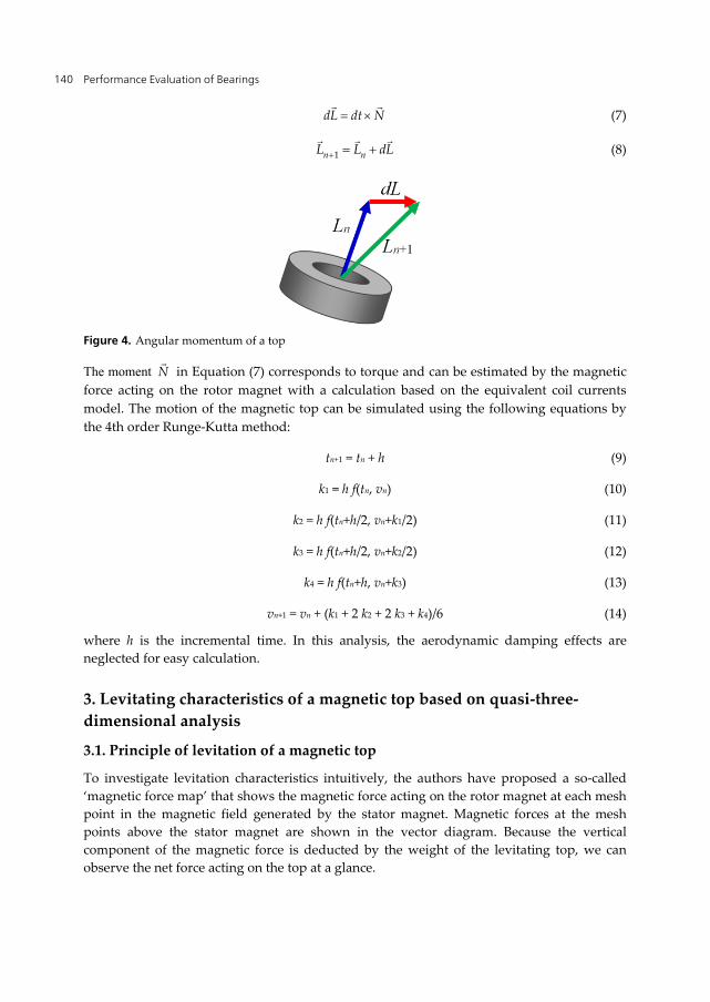
Figure 4. Angular momentum of a top
The moment N
in Equation (7) corresponds to torque and can be estimated by the magnetic
force acting on the rotor magnet with a calculation based on the equivalent coil currents
model. The motion of the magnetic top can be simulated using the following equations by
the 4th order Runge-Kutta method:
tn+1 = tn + h (9)
k1 = h f(tn, vn) (10)
k2 = h f(tn+h/2, vn+k1/2) (11)
k3 = h f(tn+h/2, vn+k2/2) (12)
k4 = h f(tn+h, vn+k3) (13)
vn+1 = vn + (k1 + 2 k2 + 2 k3 + k4)/6 (14)
where h is the incremental time. In this analysis, the aerodynamic damping effects are
neglected for easy calculation.
3. Levitating characteristics of a magnetic top based on quasi-three-
dimensional analysis
3.1. Principle of levitation of a magnetic top
To investigate levitation characteristics intuitively, the authors have proposed a so-called
‘magnetic force map’ that shows the magnetic force acting on the rotor magnet at each mesh
point in the magnetic field generated by the stator magnet. Magnetic forces at the mesh
points above the stator magnet are shown in the vector diagram. Because the vertical
component of the magnetic force is deducted by the weight of the levitating top, we can
observe the net force acting on the top at a glance.

Feasibility Study of a Passive Magnetic Bearing Using the Ring Shaped Permanent Magnets 141
Table 1 shows the parameters of the analytical model used in this chapter. These parameters
are for the experimental model introduced in Figure 1. The magnitude of current in each
equivalent side current is determined to be equal to the magnetic field density at the surface
of the permanent magnets and the measured values for the ferrite permanent magnets used
in the experiments. Considering the thickness of the permanent magnets, the number of the
equivalent current coils is set to be 2 for the rotor magnet and 24 for the stator magnet in the
simulation. Each circular coil current is simulated as a set of 72 linear current elements.
These parameters are determined considering the accuracy of calculated results and the
required time for computation.
Rotor magnet Stator magnet
Outer diameter do [mm] 30 134
Inner diameter di [mm] 12 75
Thickness h [mm] 5 60
Magnitude of equivalent current Ieq [A/mm] 286 286
Mass m [g] 20.37 -
Tilt angle θ [deg] - 1
No. of equivalent coils 2 24
No. of current elements in an equivalent coil 72 72
Table 1. Parameters used in simulation
Figure 5 shows the magnetic force map calculated for the parameters given in Table 1.
The figure shows the distribution of the magnetic force acting on the rotor magnet at
each mesh point in the vertical plane including the z–x plane. Although the magnetic
force map displays the force distribution in a two-dimensional plane, the magnetic forces
are calculated considering three-dimensional shapes and layout of the equivalent side
currents.
Figure 5(a) shows the magnetic force map in case the tilt angle of the rotor magnet is zero,
that is, the rotor magnet is laid out horizontally in the area above the stator magnet. This
figure shows that the force distribution is not uniform in the space above the stator magnet.
There are two singular points along the z-axis: points A (0, 99.5) and B (0, 91.5) (Figure 5(a)).
At point A, the magnetic forces acting on the rotor magnet are stable in the vertical direction
but unstable in the horizontal direction. On the contrary, at point B, the magnetic forces
acting on the rotor magnet are unstable in the vertical direction but stable in the horizontal
direction. These results show that the magnetic top cannot levitate when its axis is parallel to
the vertical axis; this result accords with the Earnshaw’s theorem.
Figure 5(b) shows the magnetic force map when the tilt angle of the rotor magnet θ is set to
1° in x < 0 to −1° in x > 0. This figure shows that there is a point where the magnetic forces
acting on the rotor magnet are stable in the both horizontal and vertical directions, as shown
by the point C (0, 99.5) in Figure 5(b). In other words, the magnetic forces will guide the
rotor magnet to the equilibrium point C, named as the ‘restoring centre’ in this chapter.

Performance Evaluation of Bearings 142
The quasi-three-dimensional analysis shows that there is no restoring centre when the tilt
angle of the rotor magnet is 0, but a slight tilt angle such as 1° brings the restoring centre
into existence. These results suggest that a magnetic top equipped with a ring-shaped
permanent magnet can levitate in the space above a stator ring-shaped permanent magnet if
it rotates with a slight precession.
Figure 5. Magnetic force map for different tilt angles θ of a levitating magnetic top.
3.2. Simulation to investigate the behaviour a magnetic top
To confirm the validity and effectiveness of quasi-three-dimensional analysis using the
magnetic force map, dynamic behaviour of the rotor magnet is investigated by computer
simulation based on the equations of motion introduced in the previous section. To make
intuitive discussions, a dynamic simulation using two-dimensional equations of motion,
Equations (3) and (4), is performed. In this simulation, the tilt angle of the rotor magnet is
set to θ = 1° in the area x < 0 and to −1° in the area x > 0.
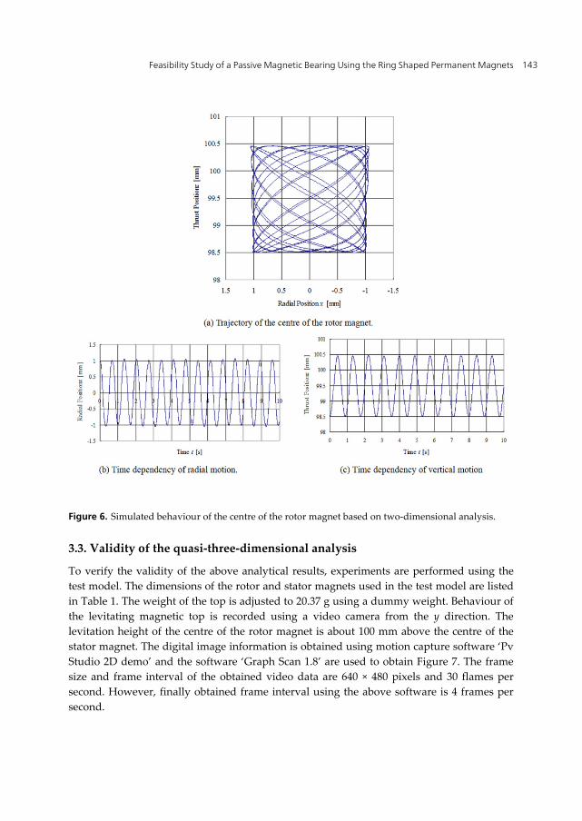
Figure 6 shows the simulated behaviour of the centre of the rotor magnet for 10 s starting
from the point (1, 98.5), which is 1 mm apart in both x and z directions from the restoring
centre (0. 99.5). The simulated time trajectory of the centre of the rotor magnet (Figure 6(a))
shows that the rotor magnet levitates in the area of ±1 mm in both vertical and horizontal
directions from the restoring centre. The bottom left point of this rectangular space is the
initial position of the rotor magnet. These results tell us that the magnetic top is swaying
around the restoring centre and the range of swaying motion is determined by the initial
position of the magnetic top with regard to the restoring centre. Figures 6 (b) and (c) show
the time dependencies of radial and vertical motions of the centre of the rotor magnet. From
these figures, we find that the frequencies of radial and vertical motions are 1.45 Hz and 1.13
Hz, respectively.
(a) θ = 0°, rotor magnet is horizontal. (b) θ = 1° with respect to z-axis.
Feasibility Study of a Passive Magnetic Bearing Using the Ring Shaped Permanent Magnets 143
Figure 6. Simulated behaviour of the centre of the rotor magnet based on two-dimensional analysis.
3.3. Validity of the quasi-three-dimensional analysis
To verify the validity of the above analytical results, experiments are performed using the
test model. The dimensions of the rotor and stator magnets used in the test model are listed
in Table 1. The weight of the top is adjusted to 20.37 g using a dummy weight. Behaviour of
the levitating magnetic top is recorded using a video camera from the y direction. The
levitation height of the centre of the rotor magnet is about 100 mm above the centre of the
stator magnet. The digital image information is obtained using motion capture software ‘Pv
Studio 2D demo’ and the software ‘Graph Scan 1.8’ are used to obtain Figure 7. The frame
size and frame interval of the obtained video data are 640 × 480 pixels and 30 flames per
second. However, finally obtained frame interval using the above software is 4 frames per
second.
Performance Evaluation of Bearings 144
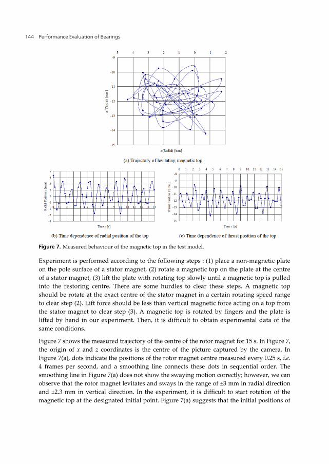
Figure 7. Measured behaviour of the magnetic top in the test model.
Experiment is performed according to the following steps : (1) place a non-magnetic plate
on the pole surface of a stator magnet, (2) rotate a magnetic top on the plate at the centre
of a stator magnet, (3) lift the plate with rotating top slowly until a magnetic top is pulled
into the restoring centre. There are some hurdles to clear these steps. A magnetic top
should be rotate at the exact centre of the stator magnet in a certain rotating speed range
to clear step (2). Lift force should be less than vertical magnetic force acting on a top from
the stator magnet to clear step (3). A magnetic top is rotated by fingers and the plate is
lifted by hand in our experiment. Then, it is difficult to obtain experimental data of the
same conditions.
Figure 7 shows the measured trajectory of the centre of the rotor magnet for 15 s. In Figure 7,
the origin of x and z coordinates is the centre of the picture captured by the camera. In
Figure 7(a), dots indicate the positions of the rotor magnet centre measured every 0.25 s, i.e.
4 frames per second, and a smoothing line connects these dots in sequential order. The
smoothing line in Figure 7(a) does not show the swaying motion correctly; however, we can
observe that the rotor magnet levitates and sways in the range of ±3 mm in radial direction
and ±2.3 mm in vertical direction. In the experiment, it is difficult to start rotation of the
magnetic top at the designated initial point. Figure 7(a) suggests that the initial positions of
Feasibility Study of a Passive Magnetic Bearing Using the Ring Shaped Permanent Magnets 145
the rotor magnet in this experiment were 3 mm and 2.3 mm apart from the restoring centres
in x and z directions, respectively. Figures 7 (b) and (c) demonstrate the time dependence of
the radial and vertical motions in 15 s. These figures show that the frequencies of swaying
motion are about 0.75 Hz in radial direction and about 1.05 Hz in vertical direction. These
test results are compared to the calculated ones in Table 2.
Measured Calculated
Levitation height [mm] 100 99.5
Frequency of radial swaying [Hz] 0.75 1.45
Frequency of vertical swaying [Hz] 1.05 1.13
Table 2. Comparison between analysis and experimental data
In spite of low accuracy of the measured data and difficulties in reenacting experiments in
the same condition, the analysed levitation height and the frequency of vertical swaying are
well in accordance with the experimental values. However, the analysed frequency of radial
swaying is about twice the experimental value. This difference seem to be derived from
assumptions in the two-dimensional analysis such as the constant tilt angle of the rotor
magnet. Simulated results for various tilt angles showed that the magnitude of the tilt angle
significantly affects the radial motion, but does not affect the vertical motion of the rotor
magnet. Furthermore, the analysis is based on two-dimensional equations of motion, and
three-dimensional behaviour of the magnetic top in the experiment is measured as two-
dimensional video information.
These results show that the fundamental parameters of a magnetic top, such as levitation
height and dimensions of the permanent magnets, can be determined well using the quasi-
three-dimensional analysis.
3.4. Levitating area and parameters of the magnets
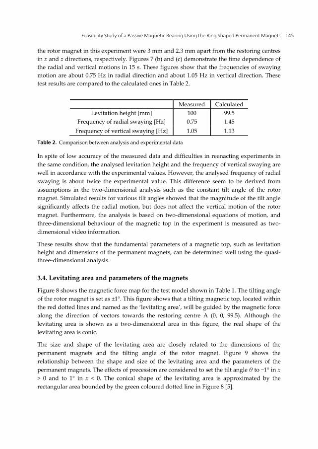
Figure 8 shows the magnetic force map for the test model shown in Table 1. The tilting angle
of the rotor magnet is set as ±1°. This figure shows that a tilting magnetic top, located within
the red dotted lines and named as the ‘levitating area’, will be guided by the magnetic force
along the direction of vectors towards the restoring centre A (0, 0, 99.5). Although the
levitating area is shown as a two-dimensional area in this figure, the real shape of the
levitating area is conic.
The size and shape of the levitating area are closely related to the dimensions of the
permanent magnets and the tilting angle of the rotor magnet. Figure 9 shows the
relationship between the shape and size of the levitating area and the parameters of the
permanent magnets. The effects of precession are considered to set the tilt angle θ to −1° in x
> 0 and to 1° in x < 0. The conical shape of the levitating area is approximated by the
rectangular area bounded by the green coloured dotted line in Figure 8 [5].
Performance Evaluation of Bearings 146
Figure 8. Levitating area of a magnetic top tilted by 1°.
Figure 9(a) shows the levitating areas and the restoring points for the various inner
diameters of the rotor magnet dri. When the inner diameter of the rotor magnet increases, the
restoring point becomes higher and the levitating area becomes narrower in the radial
direction and wider in the thrust direction. These results indicate that relatively well radial
bearing characteristics can be obtained by a rotor magnet with a large inner diameter. On
the contrary, relatively well thrust bearing characteristics can be obtained by a rotor magnet
with a smaller inner diameter.
A

Feasibility Study of a Passive Magnetic Bearing Using the Ring Shaped Permanent Magnets 147
Figure 9. Relationship between the shape and size of the levitating area and the parameters of the
permanent magnets.
Figure 9(b) shows the levitating areas and the restoring points in the case where the outer
diameter of the rotor magnet dro changes. When the outer diameter of the rotor magnet

Performance Evaluation of Bearings 148
increases, the restoring point becomes higher and the levitating area becomes narrower in
the radial direction and wider in the thrust direction. These results state that relatively well
radial bearing characteristics can be obtained by a rotor magnet with a large outer diameter.
On the contrary, relatively well thrust bearing characteristics can be obtained by a rotor
magnet with a smaller outer diameter.
Figure 9(c) shows the levitating areas and the restoring points in case where the inner
diameter of the stator magnet dsi changes. When the inner diameter of the stator magnet
increases, the restoring point becomes lower and the levitating area becomes wider in the
radial direction and narrower in the thrust direction. These results show that relatively well
radial bearing characteristics can be obtained by a stator magnet with a smaller outer
diameter. On the contrary, relatively well thrust bearing characteristics can be obtained by a
stator magnet with a larger outer diameter.
Figure 9(d) shows the levitating areas and the restoring points in the case where the outer
diameter of the stator magnet dso changes. When the outer diameter of the stator magnet
increases, the restoring point becomes higher and the levitating area becomes narrower in
the radial direction. The outer diameter of the stator magnet hardly affects the axial height
of the levitating area. These results indicate that relatively well radial bearing characteristics
can be obtained by a stator magnet with a large outer diameter. The thrust bearing
characteristics are not changed by the outer diameter of the stator magnet.
3.5. Levitating area and tilt angle of the magnets
As mentioned in the previous section, the tilting of a rotor magnet is essential in a magnetic
top. In this section, relations between the shapes of the levitating area and the tilt angle of
the rotor magnet are discussed.
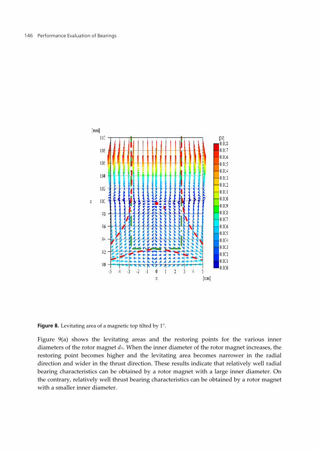
Figure 10 shows the magnetic force map with levitating areas for different tilt angles of the
rotor magnet. Figure 10(a) shows the magnetic force map when the tilt angle of the rotor
magnet is zero. The magnetic forces acting on the rotor magnet are stable in the vertical
direction but unstable in the radial direction at the upper singular point (0, 99.5). On the
contrary, the magnetic forces acting on the rotor magnet are unstable in the vertical
direction but stable in the radial direction at the lower singular point (0, 91.5). In this case,
there is no levitating area because there is no restoring centre.
Figure 10(b) shows the magnetic force map when the tilt angle of the rotor magnet is θ = 0.4°,
i.e. θ = 0.4 in the area x < 0 and θ = −0.4 in the area x > 0. Figures 10(c) and (d) show the
magnetic force maps when the tilt angle of the rotor magnet is θ = 0.8° and θ = 1.2°,
respectively. Figures 10 and 8, showing the case of θ = 1.0°, illustrate the fact that the
levitating area becomes wider when the tilt angle becomes larger up to 1.2°, while the
magnitude of restoring force around the restoring centre becomes saturated. We can
intuitively observe considering the behaviour of a normal top that a magnetic top with a
very large tilting angle will not levitate. Figure 10 also shows that the height of the restoring
centre does not change by the tilt angle of the rotor magnet.
Feasibility Study of a Passive Magnetic Bearing Using the Ring Shaped Permanent Magnets 149

Performance Evaluation of Bearings 150
Figure 10. Relationship between the levitating area and the tilt angle of the rotor magnet.

Feasibility Study of a Passive Magnetic Bearing Using the Ring Shaped Permanent Magnets 151
4. Study of the dynamic behaviour of a magnetic top by three-
dimensional analysis
We can obtain approximate guidelines for the size and shape of the levitating area by quasi-
three-dimensional analysis. Although the static analysis gives the ‘levitating area’, a
magnetic top in this area may not always continue to levitate, considering the dynamic
motion of the top. Furthermore, the static analysis mentioned in the previous section
showed that the magnitude of the restoring force acting on the rotor magnet was small.
Because the quasi-three-dimensional static analysis provides an approximate design of the
magnetic top, the three-dimensional dynamic analysis should be performed to confirm
whether the rotating magnetic top can maintain levitation.
In this section, how the parameters such as rotating speed, mass of the top and initial
position with regard to the restoring centre affect the behaviour of the levitating magnetic
top is discussed.
4.1. Effects of rotating speed
To realise a successful rotation of a magnetic top, the rotation speed is one of the most
important parameters. Simulated results show that the magnetic top (Table 1) can maintain
levitating while it rotates in the range of 18–50 rps, i.e. 1,080–3,000 rpm, when the initial
position is 1 mm apart in both radial and vertical directions from the restoring centre.
Figures 11(a) and (b) show the trajectories of the centre of the magnetic top rotating at 1020
rpm and 3240 rpm, respectively. This characteristic is closely related to the tilt angle of the
rotor magnet, that is, the rotor magnet with the shaft rotating at very low speed cannot
maintain an adequate tilt angle because of the lack of mechanical inertia and the rotor
magnet with the shaft rotating at a very high speed cannot maintain its tilt angle stable
because of the increasing centrifugal force.
Figure 12 shows the typical time dependency of the tilt angle of the rotor magnet. The tilt
angle in this figure indicates the absolute values, i.e. the rotor magnet is tilting in a radial
direction around z-axis. As shown in this figure, the tilt angle θ varies within 1.2° while the
rotor magnet levitates with precession, as in this case. The maximum value of the tilt angle
increases with increase in the rotation speed of the rotor magnet, as shown in Figure 13. In
this analytical model, the gravity centre of the magnetic top is located at a little upper point
along its shaft from the centre of the rotor magnet; therefore, the tilt angle becomes larger
with an increase in the rotating speed. Then, the rotor magnet will be thrown in the radial
direction, along the magnetic force vectors shown in Figure 10(a). If we design a magnetic
top with the gravity centre located at the centre of the rotor magnet, the rotor magnet will
rotate without tilting because of its mechanical inertia; however, such a rotor magnet cannot
realise levitation, according to previous discussions.
Figure 14 shows the simulated trajectories of a levitating magnetic top rotating at 1,080 rpm
for 60 s after starting from point (1, 0, 98.5), which is 1 mm apart from the restoring centre in

Performance Evaluation of Bearings 152
both x and z directions. Figures 14(a) and (b) show the trajectories of the head of the 25 mm
long shaft of the magnetic top and Figures 14(c) and (d) show the trajectories of the centre of
the rotor magnet. Figures 14(a) and (b) show that the shaft head rotates with both smaller
radius nutation and larger radius precession. On the other hand, Figures 14(c) and (d) show
that the centre of the rotor magnet rotates with precession when the tilt angle varies
periodically. Comparing these two figures, it is observed that a magnetic top, rotating at a
low speed such as 1,080 rpm, is rotating in a complex motion with nutation mode in
addition to precession mode [6].
Figure 11. Trajectories of the magnetic top for 5 s.
Figure 12. Time dependency of the tilt angle of the rotor magnet.

Feasibility Study of a Passive Magnetic Bearing Using the Ring Shaped Permanent Magnets 153
Figure 13. The maximum tilt angle θ vs. rotating speed.
Figure 15 shows the simulated trajectories of a levitating magnetic top rotating at 3,000 rpm
for 60 s after starting at point (1, 0, 98.5). Figures 15(a) and (b) show the trajectories of the
head of the 25 mm long shaft of the magnetic top and Figures 15(c) and (d) show the
trajectories of the centre of the rotor magnet. From these figures, we can observe that both
the trajectories of the shaft head and the centre of the rotor magnet are almost the same in
shape. However, the shaft head rotates in a little wider range compared to the moving area
of the centre of the rotor magnet. This means that a magnetic top rotating at a relatively
higher speed, e.g. 3,000 rpm, maintains its levitation with precession mode. In this case,
nutation mode is hardly observed.
Although it is difficult to repeat the experiments in the same conditions, these simulated
results showed good accordance with the experiments [6].

Performance Evaluation of Bearings 154
Figure 14. Simulated trajectories of the levitating magnetic top rotating at 1,080 rpm.
Figure 15. Simulated trajectories of the levitating magnetic top rotating at 3,000 rpm.
Feasibility Study of a Passive Magnetic Bearing Using the Ring Shaped Permanent Magnets 155
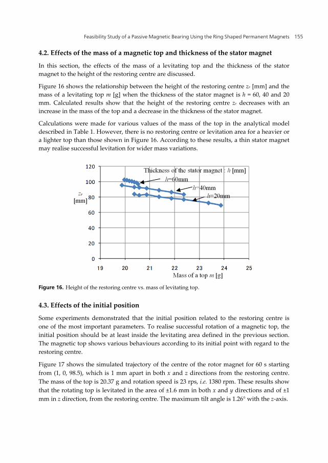
4.2. Effects of the mass of a magnetic top and thickness of the stator magnet
In this section, the effects of the mass of a levitating top and the thickness of the stator
magnet to the height of the restoring centre are discussed.
Figure 16 shows the relationship between the height of the restoring centre zr [mm] and the
mass of a levitating top m [g] when the thickness of the stator magnet is h = 60, 40 and 20
mm. Calculated results show that the height of the restoring centre zr decreases with an
increase in the mass of the top and a decrease in the thickness of the stator magnet.
Calculations were made for various values of the mass of the top in the analytical model
described in Table 1. However, there is no restoring centre or levitation area for a heavier or
a lighter top than those shown in Figure 16. According to these results, a thin stator magnet
may realise successful levitation for wider mass variations.
Figure 16. Height of the restoring centre vs. mass of levitating top.
4.3. Effects of the initial position
Some experiments demonstrated that the initial position related to the restoring centre is
one of the most important parameters. To realise successful rotation of a magnetic top, the
initial position should be at least inside the levitating area defined in the previous section.
The magnetic top shows various behaviours according to its initial point with regard to the
restoring centre.
Figure 17 shows the simulated trajectory of the centre of the rotor magnet for 60 s starting
from (1, 0, 98.5), which is 1 mm apart in both x and z directions from the restoring centre.
The mass of the top is 20.37 g and rotation speed is 23 rps, i.e. 1380 rpm. These results show
that the rotating top is levitated in the area of ±1.6 mm in both x and y directions and of ±1
mm in z direction, from the restoring centre. The maximum tilt angle is 1.26° with the z-axis.

Performance Evaluation of Bearings 156
To investigate the effects of the initial point with regard to the restoring centre (0, 0, 99.5),
simulations were performed for the case of the typical initial point of (1, 0, 99.5), i.e. 1 mm
apart in x direction from the restoring centre, and (0, 0, 98.5), i.e. 1 mm apart in z direction
from the restoring centre. Figures 18(a) and (b) show the simulated trajectories of the centre
of the rotor magnet, rotating at 1,380 rpm for 60 s starting from (1, 0, 99.5) and (0, 0, 98.5),
respectively.
The magnetic top, starting from the point 1 mm apart in x direction from the restoring
centre, levitates in the range of ±1.07 mm in both x and y directions and from +0.12 mm/ to
0.06 mm in z direction around the restoring centre, as shown in Figure 18(a). The maximum
tilt angle is 1.018°.
Figure 17. Simulated trajectories of a magnetic top in 60 s starting from (1, 0, 98.5), 1380 rpm.
Figure 18. Trajectories of the centre of the rotor magnet in z–x plane.
Feasibility Study of a Passive Magnetic Bearing Using the Ring Shaped Permanent Magnets 157
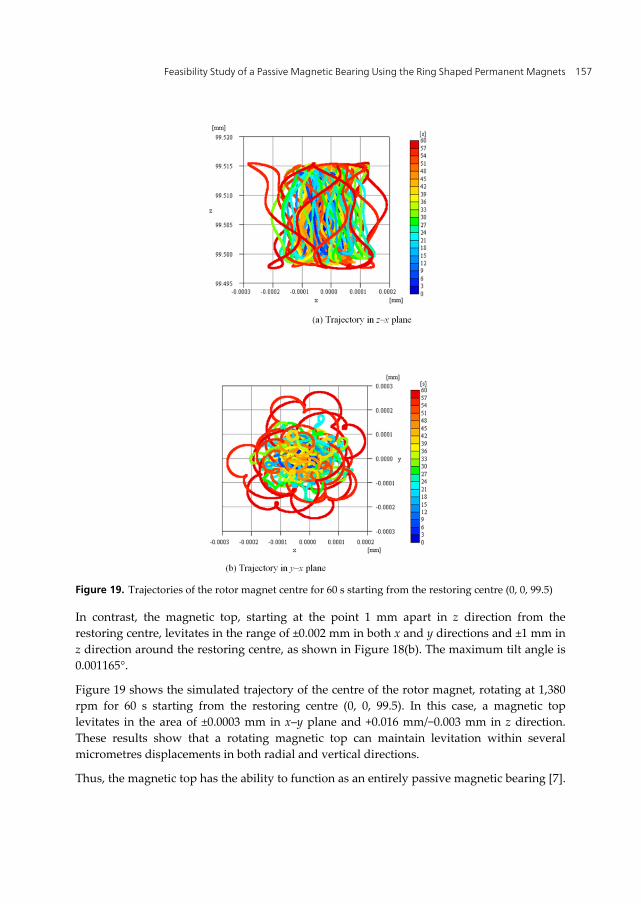
Figure 19. Trajectories of the rotor magnet centre for 60 s starting from the restoring centre (0, 0, 99.5)
In contrast, the magnetic top, starting at the point 1 mm apart in z direction from the
restoring centre, levitates in the range of ±0.002 mm in both x and y directions and ±1 mm in
z direction around the restoring centre, as shown in Figure 18(b). The maximum tilt angle is
0.001165°.
Figure 19 shows the simulated trajectory of the centre of the rotor magnet, rotating at 1,380
rpm for 60 s starting from the restoring centre (0, 0, 99.5). In this case, a magnetic top
levitates in the area of ±0.0003 mm in x–y plane and +0.016 mm/−0.003 mm in z direction.
These results show that a rotating magnetic top can maintain levitation within several
micrometres displacements in both radial and vertical directions.
Thus, the magnetic top has the ability to function as an entirely passive magnetic bearing [7].

Performance Evaluation of Bearings 158
4.4. Effects of the air drag force
In the previous analysis, the aerodynamic effects were neglected to simplify the discussion.
If a magnetic top is rotating in air, rotating speed of the top will decay because of the
pneumatic resistance acting on the surfaces of the top. In actual, the experiments showed
that the rotating speed of the magnetic top decreases as time passes and the attitude of the
top changes to a larger precession that leads it to fall down in a few minutes. Because there
are no conducting materials in the magnetic top, there is no electrodynamic drag force
caused by eddy currents. Hence, the aerodynamic drag force can be considered as the main
reason for the decreasing rotation speed. In this section, some simulations are performed
based on the equations of motion considering the aerodynamic drag force.
The aerodynamic effects to the behaviour of a rotating magnetic top is estimated as the
pneumatic resistance acting on the outer side surface of the magnetic top. Here, the
aerodynamic drag effects caused by the pole surfaces of the magnetic top are neglected. The
following expressions are added to estimate the aerodynamic effects to the rotating speed of
the magnetic top:
1d
n nTop
Fdt
I (15)
21
2d d r r roF C A v r (16)
where ρ = 1.225 kg/m3 is the density of air, CD is the coefficient of pneumatic resistance, Ar =
2πrroh is the area of the outer side surface of the top and vr = rroω is the velocity of the outer
side surface of the rotating top [8].
Figure 20. Simulated trajectory of the levitating magnet centre, initial rotating speed is 1380 rpm.

Feasibility Study of a Passive Magnetic Bearing Using the Ring Shaped Permanent Magnets 159
Figure 21. Time dependence of rotating speed and tilt angle of a levitating magnetic top.
Figure 22. Trajectories of a levitating magnetic top started at 1380 rpm and fall down at 275 s after start.
Figure 20 shows the simulated trajectory of the centre of the levitating magnet starting from
1 mm apart in both x and z directions from the restoring centre. Initial rotation speed is set
to be 1,380 rpm. The coefficient of pneumatic resistance CD is set to be 0.5 for Figure 20(a)
and 5.0 for Figure 20(b). Figure 20 shows that the magnetic top can levitate for 275 s or 28.4
s, if the coefficient of pneumatic resistance CD is 0.5 or 5.0, respectively. Experiments showed
that the magnetic top can be levitated for 3–4 min. Hence, in this study, the coefficient of
pneumatic resitance CD is assumed to be 0.5.
Figure 21 shows the time dependence of the rotation speed and the tilt angle of the
levitating magnetic top. Figure 21(a) shows that the magnetic top started at 1,380 rpm and
maintained levitation till 166 rpm at 275 s.

Performance Evaluation of Bearings 160
Figure 21(b) shows the time dependence of the tilt angle of the rotor magnet with respect to
z-axis. This figure shows that the tilt angle varies within 1.4° while the top is levitating and
indicates that precession is needed to maintain levitation for a magnetic top.
Figure 22 shows the trajectories of the magnetic top at the last 15 s of its levitation. Figures
22(a) and (b) demonstrate the trajectories of the shaft head and the centre of the levitating
rotor magnet in its final 15 s levitation. These figures show that the precession quickly
becomes larger once the magnetic top exits the levitating area.
5. Conclusions
A magnetic top levitates by itself, without any active control system, so long as it rotates in a
certain speed range. The authors propose a simple and intuitive analysing method to predict
characteristics of the magnetic top.
The quasi-three-dimensional static analysis, considering shapes and layout of the ring-
shaped rotor and stator magnets, is used to explain the principle of levitation and obtain the
preliminary design parameters of the rotor and stator magnets. The behaviour of the
magnetic top is also investigated by dynamic simulations based on the three-dimensional
equations of motion considering the moment of inertia for the rotating magnetic top. The
following results are obtained:
1. A magnetic top can levitate when it rotates in precession mode with a slight tilting
angle and in a certain rotating speed range.
2. The effects of the parameters, such as outer and inner diameters of the rotor and stator
magnets, to the behaviour of the magnetic top can be discussed by the quasi-three-
dimensional static analysis.
3. A magnetic top rotating at a low speed levitates in both precession and nutation modes.
On the contrary, a magnetic top rotating at a high speed levitates with precession, and
nutation mode is not observed.
4. The lowest rotation speed is determined to maintain the attitude of the rotating magnet
using its mechanical inertia. The maximum rotation speed is limited by the centrifugal
force that increases the tilt angle of the shaft of the magnetic top.
5. A magnetic top starting its rotation at the restoring centre will maintain its position
with the accuracy of several micrometres.
6. It is difficult to repeat experiments of a magnetic top in the same conditions. However,
the proposed analytical results showed good accordance with the experimental data
observed using a digital video camera.
A magnetic top may be used as a rotating demonstration model in which some swaying
motion can be permitted such as in toys or other relaxation items. When a magnetic top is
used in commercial system, a rotor should be rotated by some non-contact drive mechanism
such as electric motor or air turbine, etc. Furthermore, touch down bearing should be
equipped to suspend a rotor while rotating speed is out of operating range. Fundamental
requirements to design a magnetic bearing based on the principle of a magnetic top will be
Feasibility Study of a Passive Magnetic Bearing Using the Ring Shaped Permanent Magnets 161
rotor weight and rotation speed. A rotor shaft should be designed considering mechanical
requirements such as torque.
In the experimantal model, because ferrite magnets are used for the rotor and stator
magnets, the restoring forces are very small for commercial applications. However, if rare
earth permanent magnets and rigid suspension devices are used, sufficient restoring forces
may be expected to be generated for use as a commercial passive magnetic
bearing.
Author details
Teruo Azukuzawa
Japan Transport Safety Board, Tokyo, Japan
Shigehiro Yamamoto
Graduate School of Maritime Sciences, Kobe University, Kobe, Japan
Acknowledgement
The authors thank Mr. Makoto Matsumoto, former student of the Graduate school of
Natural Science and Technology, Kobe University, for his efforts in establishing simulation
tools for analysing the dynamic behaviour of a magnetic top.
6. References
[1] The Magnetic Levitation Technical Committee of the IEEJ (1993) Magnetic Suspension
Technology - Magnetic Levitation Systems and Magnetic Bearings. Corona Publishing
Co. Ltd., in Japanese.
[2] Matsumoto M, Azukizawa T (2004) Characteristics of Magnetic Guidance Force Between
Coaxial Ring Shaped Permanent Magnets. IEEJ Technical Meetings on Linear Drives,
LD-04-93, in Japanese.
[3] Miguel A.S. et al. (2005) Numerical integration for the dynamics of the heavy magnetic
top. Physics Letters A 335 235–244.
[4] Ebihara D , Suzuki T (1988) The Repulsive Characteristics of the PM Type Magnetic
Levitation Devices. Trans. IEEJ, Vol.108-D, No.5, 455-461, in Japanese.
[5] Azukizawa T, Matsuo N (2007) Feasibility Study of a Magnetic Top As a Magnetic
Bearing. Proc. of the 6th International Symposium on Linear Drives for Industrial
Applications, LDIA 2007(CD), 138.
[6] Azukizawa T, Yamamoto S, Matsuo N (2008) Feasibility Study of a Passive Magnetic
Bearing Using the Ring Shaped Permanent Magnets. IEEE Trans. on Mag., Vol.44,
No.11, 4277-4280.
[7] Azukizawa T, Yamamoto S, Makino H (2008) Effects of the System Parameters to the
Behavior of a Magnetic Top. MAGLEV08, No. 63.

Performance Evaluation of Bearings 162
[8] Azukizawa T, Yamamoto S, Makino H (2009) Analysis of Dynamic Behavior of a
Magnetic Top Considering Aerodynamic Drag Force. LDIA2009


![The Economic Feasibility of Passive Houses in Korea...implementing passive houses [8]. Despite the energy-saving advantages of building a passive house, high investment costs, ambiguous](https://img.pdfslide.net/doc/110x75/60ea61ef75f7883d166b9ddd/the-economic-feasibility-of-passive-houses-in-korea-implementing-passive-houses.jpg)