Embed Size (px)
Citation preview
©2016 nHance Technologies, Inc. p 434.582.6110 w nHancetech.com
Features of the Modular Modeling System (MMS) Simulation Development Environment
2 Features of the Modular Modeling System v2.3 | ©2016 nHance Technologies, Inc. p 434.582.6110 w nHancetech.com
Table of Contents 1. Overview ..................................................................................... 3
1.1 MMS Model .................................................................................. 51.2 Control Logic Modeling .................................................................. 5
2. Constructing an MMS Process Model ............................................. 5
2.1 Description of MMS User Input Data ................................................ 62.2 Model Input and Output Variable Structure ....................................... 62.3 Model Tuning ............................................................................... 6
3. The Modular Modeling System (MMS) ........................................... 6
3.1 Introduction ................................................................................ 63.2 The MMS Model Builder ................................................................. 63.2.1 Viewing Models with the Model Builder .......................................... 73.2.2 Graphically Building a Model ........................................................ 73.2.3 Customization, Presentation, Text and Aesthetic Features ................ 93.2.4 Module Data Input ..................................................................... 93.2.5 Parameter Passing ................................................................... 103.2.6 Combined Auto-Parameterization with Parameter Passing ............... 113.3 Expanding MMS with Customized Modules ...................................... 11
4. Instructor Station Tools ............................................................. 12
4.1 Action Center ............................................................................. 124.1.1 Action Variable List .................................................................. 144.1.2 Action List .............................................................................. 154.2 Graph Master ............................................................................. 154.2.1 Trainee Proficiency Review ........................................................ 16
5. Support ..................................................................................... 18
5.1 nHance Help System ................................................................... 185.2 MMS Professionals Program .......................................................... 185.3 Simulator Maintenance Plans ........................................................ 18
6. nCloud Setup ............................................................................. 19
Features of the Modular Modeling System v2.3 | ©2016 nHance Technologies, Inc. p 434.582.6110 w nHancetech.com 3
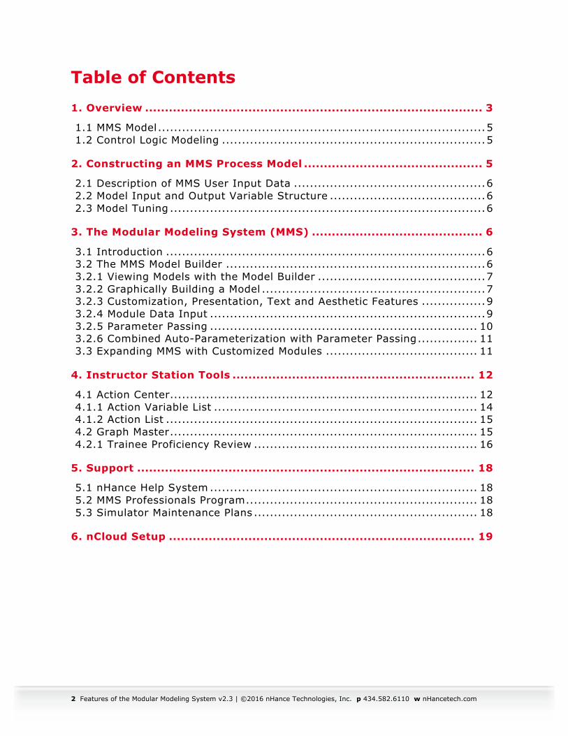
1. Overview This document provides an overview of nHance Technologies’ simulator process modeling system, the Modular Modeling System (MMS™), and brief descriptions of complementary software tools beneficial for training simulator uses and other applications such as control hardware-in-the-loop studies. The simulation software consists of several applications, each running on a number of different computers. All of nHance Technologies’ simulation software is capable of being executed on Microsoft Windows based computers. The computers used are generally broken down into categories according to the tasks they perform as depicted in the figure below.
Figure 1: Typical nHance Training System Overview
The MMS Simulation Tools software package is a collection of applications that are designed to work together to transition an MMS model from engineering analysis to a complete replica operator-training simulator. These packages are designed to work with a process model and are capable of running on a single physical computer or can be separated into multiple networked computers to
4 Features of the Modular Modeling System v2.3 | ©2016 nHance Technologies, Inc. p 434.582.6110 w nHancetech.com
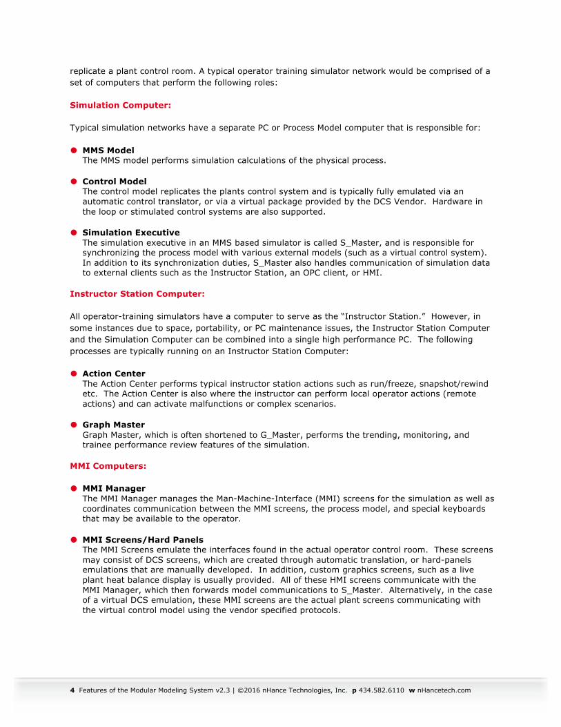
replicate a plant control room. A typical operator training simulator network would be comprised of a set of computers that perform the following roles:
Simulation Computer:
Typical simulation networks have a separate PC or Process Model computer that is responsible for:
� MMS Model The MMS model performs simulation calculations of the physical process.
� Control Model The control model replicates the plants control system and is typically fully emulated via an automatic control translator, or via a virtual package provided by the DCS Vendor. Hardware in the loop or stimulated control systems are also supported.
� Simulation Executive The simulation executive in an MMS based simulator is called S_Master, and is responsible for synchronizing the process model with various external models (such as a virtual control system). In addition to its synchronization duties, S_Master also handles communication of simulation data to external clients such as the Instructor Station, an OPC client, or HMI.
Instructor Station Computer:
All operator-training simulators have a computer to serve as the “Instructor Station.” However, in some instances due to space, portability, or PC maintenance issues, the Instructor Station Computer and the Simulation Computer can be combined into a single high performance PC. The following processes are typically running on an Instructor Station Computer:
� Action Center The Action Center performs typical instructor station actions such as run/freeze, snapshot/rewind etc. The Action Center is also where the instructor can perform local operator actions (remote actions) and can activate malfunctions or complex scenarios.
� Graph Master Graph Master, which is often shortened to G_Master, performs the trending, monitoring, and trainee performance review features of the simulation.
MMI Computers:
� MMI Manager The MMI Manager manages the Man-Machine-Interface (MMI) screens for the simulation as well as coordinates communication between the MMI screens, the process model, and special keyboards that may be available to the operator.
� MMI Screens/Hard Panels The MMI Screens emulate the interfaces found in the actual operator control room. These screens may consist of DCS screens, which are created through automatic translation, or hard-panels emulations that are manually developed. In addition, custom graphics screens, such as a live plant heat balance display is usually provided. All of these HMI screens communicate with the MMI Manager, which then forwards model communications to S_Master. Alternatively, in the case of a virtual DCS emulation, these MMI screens are the actual plant screens communicating with the virtual control model using the vendor specified protocols.
Features of the Modular Modeling System v2.3 | ©2016 nHance Technologies, Inc. p 434.582.6110 w nHancetech.com 5
1.1 MMS Model Creating a physical-process model from plant drawings and component data is a complex task if performed without the benefit of advanced modeling tools such as the Modular Modeling System (MMS). Although it is possible to write a custom program to simulate a plant, the use of a pre-engineered component-oriented modeling library is more efficient and allows for the reuse of well-tested code. With MMS, the plant model for a simulator is built using these components or “modules” that represent power plant equipment such as pipes, pumps, turbines, boilers, etc. In addition, MMS uses an advanced numerical algorithm for real-time computation that is typically much faster than temporal algorithms and well suited for real-time simulator applications. The act of building an MMS model is simplified by the use of a graphical pre-processor program known as the MMS Model Builder.
1.2 Control Logic Modeling A critical requirement of any power plant simulation is the accurate representation of the control system. Control logic can be modeled using MMS based upon functional requirements (Functional Emulation), or automatically via the use of a conversion program known as a “translator.” A recent term used by Control System Vendors is the term “Virtual” to describe control system emulation. Since there is no universal definition of ”Virtual Control System emulation,” we define the term to mean a software based control system simulator that is provided, supported, and maintained by the DCS vendor.
In addition to emulating the control system, the actual hardware can be used by fooling it into believing that it is communicating with actual plant I/O, by driving the I/O from the simulator. This is typically known as “Hardware In the Loop” or a “stimulated” control system. With the advance of recent virtualization techniques supported by the various control system vendors true hardware in the loop stimulated systems are rare, and as a result, “Virtual” and “Stimulated” are sometimes used interchangeably.
2. Constructing an MMS Process Model The major steps in constructing an MMS process model are:
� Determine plant systems and components to be simulated
� Collect physical and operating point data
� Select corresponding MMS modules
� Construct an MMS model using the MMS Model Builder
� Enter component data on the MMS input Form, calculate parameters by using the auto-parameterization feature, and fill in gaps in available plant data with engineering judgment
� Test and Tune to operating point data
6 Features of the Modular Modeling System v2.3 | ©2016 nHance Technologies, Inc. p 434.582.6110 w nHancetech.com
2.1 Description of MMS User Input Data The input data requirements vary from component to component and are sometimes extensive. The MMS documentation defines the input data and suggests how various input data may be obtained from operating data or from vendor specifications. When setting up a simulation, the MMS Model Builder requires data input to be completed for each module. The “auto-parameterization routines” assist the user in constructing useful data from available parameters. Sometimes, however, MMS, like all other simulation platforms requires a degree of engineering judgment when data is not available, and our pre-engineered modules assist the engineer with default or typical values to use as a starting point.
2.2 Model Input and Output Variable Structure The plant model is a program consisting of invocations of mini-models representing various plant components called “Modules.” Each module invocation includes arguments that specify how each module is interconnected with other modules and parameters that characterize the component and the initial conditions (initial operating point values) of the component. These module invocations are setup automatically for the user when using the MMS Model Builder. However, unlike other modeling systems, MMS is not a “black box” modeling tool. A description of the modeling assumptions and theory along with specific input data for each MMS module and how it is “invoked” is fully described on the integrated MMS help file for that module. This documentation is of great benefit to the end user when testing and tuning the overall model, and when expanding MMS with custom modules.
2.3 Model Tuning During the testing and tuning stage, the user with the appropriate Instructor Station or runtime commands can tune almost all input data dynamically. The simulation engineer will typically develop command scripts or “Procedures” to drive the model to various states for testing and model performance evaluation. A special feature unique to the Modular Modeling System is the ease with which the engineer can perform these tests and evaluations, and is a major reason why MMS is popular as an engineering analysis tool in addition to its use for operator training simulators.
3. The Modular Modeling System (MMS) 3.1 Introduction The Modular Modeling System (MMS) is a set of software programs, libraries, and tools that are collectively designed to offer the simulation engineer many timesaving, user-friendly features that make simulation model development easier and more productive.
3.2 The MMS Model Builder The MMS Model Builder allows the user to quickly build a graphical schematic representation for a plant by selecting from a library of pre-engineered power plant components called “Modules.” In addition, each MMS module has a calculation subroutine that facilitates the determination of a steady-state condition and assists the user in component specific parameter calculations. This feature, termed “auto-parameterization,” helps avoid repetitive and often tedious hand calculations for model initialization. The Model Builder was designed to provide a model schematic and a simple means to enter component data via on-screen input forms. The Model Builder enables the user to graphically “build” models by selecting plant components from a menu of modules, positioning them
Features of the Modular Modeling System v2.3 | ©2016 nHance Technologies, Inc. p 434.582.6110 w nHancetech.com 7
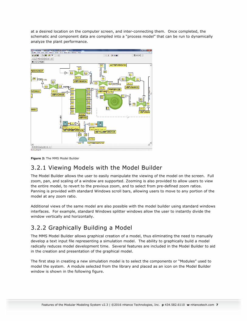
at a desired location on the computer screen, and inter-connecting them. Once completed, the schematic and component data are compiled into a “process model” that can be run to dynamically analyze the plant performance.
Figure 2: The MMS Model Builder
3.2.1 Viewing Models with the Model Builder The Model Builder allows the user to easily manipulate the viewing of the model on the screen. Full zoom, pan, and scaling of a window are supported. Zooming is also provided to allow users to view the entire model, to revert to the previous zoom, and to select from pre-defined zoom ratios. Panning is provided with standard Windows scroll bars, allowing users to move to any portion of the model at any zoom ratio.
Additional views of the same model are also possible with the model builder using standard windows interfaces. For example, standard Windows splitter windows allow the user to instantly divide the window vertically and horizontally.
3.2.2 Graphically Building a Model The MMS Model Builder allows graphical creation of a model, thus eliminating the need to manually develop a text input file representing a simulation model. The ability to graphically build a model radically reduces model development time. Several features are included in the Model Builder to aid in the creation and presentation of the graphical model.
The first step in creating a new simulation model is to select the components or “Modules” used to model the system. A module selected from the library and placed as an icon on the Model Builder window is shown in the following figure.
8 Features of the Modular Modeling System v2.3 | ©2016 nHance Technologies, Inc. p 434.582.6110 w nHancetech.com
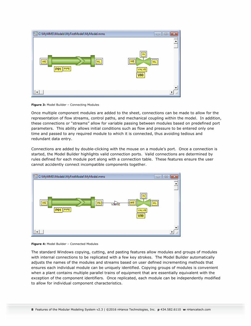
Figure 3: Model Builder – Connecting Modules
Once multiple component modules are added to the sheet, connections can be made to allow for the representation of flow streams, control paths, and mechanical coupling within the model. In addition, these connections or “streams” allow for variable passing between modules based on predefined port parameters. This ability allows initial conditions such as flow and pressure to be entered only one time and passed to any required module to which it is connected, thus avoiding tedious and redundant data entry.
Connections are added by double-clicking with the mouse on a module’s port. Once a connection is started, the Model Builder highlights valid connection ports. Valid connections are determined by rules defined for each module port along with a connection table. These features ensure the user cannot accidently connect incompatible components together.
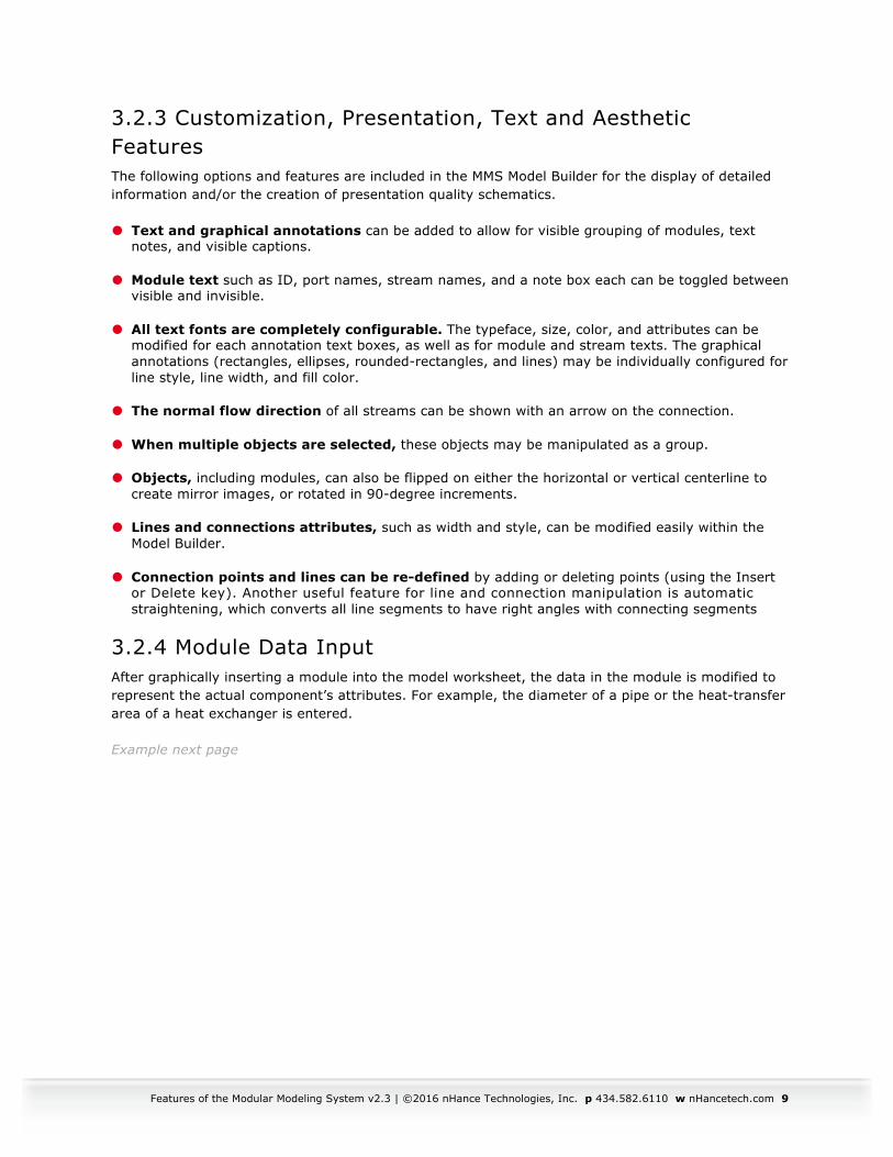
Figure 4: Model Builder – Connected Modules
The standard Windows copying, cutting, and pasting features allow modules and groups of modules with internal connections to be replicated with a few key strokes. The Model Builder automatically adjusts the names of the modules and streams based on user defined incrementing methods that ensures each individual module can be uniquely identified. Copying groups of modules is convenient when a plant contains multiple parallel trains of equipment that are essentially equivalent with the exception of the component identifiers. Once replicated, each module can be independently modified to allow for individual component characteristics.
Features of the Modular Modeling System v2.3 | ©2016 nHance Technologies, Inc. p 434.582.6110 w nHancetech.com 9
3.2.3 Customization, Presentation, Text and Aesthetic Features The following options and features are included in the MMS Model Builder for the display of detailed information and/or the creation of presentation quality schematics.
� Text and graphical annotations can be added to allow for visible grouping of modules, text notes, and visible captions.
� Module text such as ID, port names, stream names, and a note box each can be toggled between visible and invisible.
� All text fonts are completely configurable. The typeface, size, color, and attributes can be modified for each annotation text boxes, as well as for module and stream texts. The graphical annotations (rectangles, ellipses, rounded-rectangles, and lines) may be individually configured for line style, line width, and fill color.
� The normal flow direction of all streams can be shown with an arrow on the connection.
� When multiple objects are selected, these objects may be manipulated as a group.
� Objects, including modules, can also be flipped on either the horizontal or vertical centerline to create mirror images, or rotated in 90-degree increments.
� Lines and connections attributes, such as width and style, can be modified easily within the Model Builder.
� Connection points and lines can be re-defined by adding or deleting points (using the Insert or Delete key). Another useful feature for line and connection manipulation is automatic straightening, which converts all line segments to have right angles with connecting segments
3.2.4 Module Data Input After graphically inserting a module into the model worksheet, the data in the module is modified to represent the actual component’s attributes. For example, the diameter of a pipe or the heat-transfer area of a heat exchanger is entered.
Example next page
10 Features of the Modular Modeling System v2.3 | ©2016 nHance Technologies, Inc. p 434.582.6110 w nHancetech.com
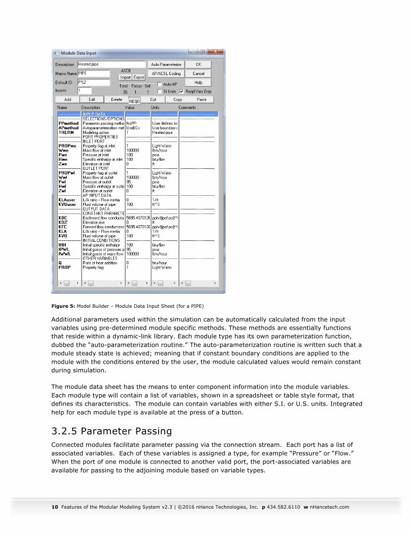
Figure 5: Model Builder – Module Data Input Sheet (for a PIPE)
Additional parameters used within the simulation can be automatically calculated from the input variables using pre-determined module specific methods. These methods are essentially functions that reside within a dynamic-link library. Each module type has its own parameterization function, dubbed the “auto-parameterization routine.” The auto-parameterization routine is written such that a module steady state is achieved; meaning that if constant boundary conditions are applied to the module with the conditions entered by the user, the module calculated values would remain constant during simulation.
The module data sheet has the means to enter component information into the module variables. Each module type will contain a list of variables, shown in a spreadsheet or table style format, that defines its characteristics. The module can contain variables with either S.I. or U.S. units. Integrated help for each module type is available at the press of a button.
3.2.5 Parameter Passing Connected modules facilitate parameter passing via the connection stream. Each port has a list of associated variables. Each of these variables is assigned a type, for example “Pressure” or “Flow.” When the port of one module is connected to another valid port, the port-associated variables are available for passing to the adjoining module based on variable types.
Features of the Modular Modeling System v2.3 | ©2016 nHance Technologies, Inc. p 434.582.6110 w nHancetech.com 11
Parameter passing is an extremely powerful method of quickly initializing the port variables (boundary conditions) of the modules. This feature eliminates the need for tedious and redundant data entry.
3.2.6 Combined Auto-Parameterization with Parameter Passing Another powerful, timesaving feature combines auto-parameterization with parameter passing. The Model Builder can automatically define all boundary conditions for a selected group or “Train” of modules. The auto-parameterization will calculate pressure drops and flow splits within modules and pass the resulting outlet pressures and flows to the next module, thus defining the entire pressure and flow distribution with no user interaction. This feature is similar to calculating a steady state for the system and parameterizing each module independently based upon the steady state.
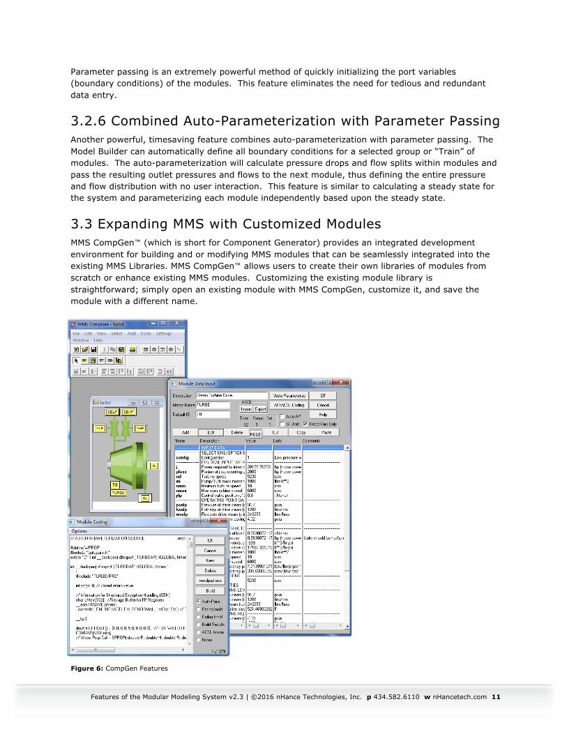
3.3 Expanding MMS with Customized Modules MMS CompGen™ (which is short for Component Generator) provides an integrated development environment for building and or modifying MMS modules that can be seamlessly integrated into the existing MMS Libraries. MMS CompGen™ allows users to create their own libraries of modules from scratch or enhance existing MMS modules. Customizing the existing module library is straightforward; simply open an existing module with MMS CompGen, customize it, and save the module with a different name.
Figure 6: CompGen Features
12 Features of the Modular Modeling System v2.3 | ©2016 nHance Technologies, Inc. p 434.582.6110 w nHancetech.com
CompGen enables the creation of custom modules with the following features:
� Drawing tools for creating module icons
� Annotation text placement
� Worksheet with complete variable editing
� Port connection relationship definitions
� Auto-parameterization (AP) code editing
� Template generation wizard for starting AP coding
� Integrated Microsoft Visual C++ building of the AP code
� On-screen help
4. Instructor Station Tools nHance Technologies’ Instructor Station Tools are separated into two main tool sets:
Action Center: for typical instructor station operation
Graph Master: for trending and trainee performance review.
Training simulation standards require a method to control the training simulator’s basic functions such as run, freeze, initialization, snapshot, backtrack, time scaling, and invocation of malfunctions/scenarios. These particular functions are typically called Instructor Station functions as they are performed on a dedicated computer system that exchanges data over a network with the other simulator system computers. nHance Technologies has extended this basic concept to enhance the instructor capabilities, productivity, and flexibility to readily adapt functions such as scenarios and malfunctions easily and quickly without any low-level programming or rebuilding of the process model.
The bulk of the Training Simulator documentation for the purpose of operator training is provided by extensive help file documentation. This documentation explains the training simulator Instructor and development functions. The documentation is readily available in PDF (Adobe Acrobat Reader) file format for high quality printing.
4.1 Action Center The Action Center software is an easy-to-use program for interactive model control that provides real-time variable trending and model performance review, and performs typical
instructor station model features (load/save ic’s, initiate malfunctions, etc.).

Features of the Modular Modeling System v2.3 | ©2016 nHance Technologies, Inc. p 434.582.6110 w nHancetech.com 13
The Action Center, shown below, provides a layered approach that meets both objectives:
� Ease of instructor model control
� Straightforward extension of model operations (e.g., add new malfunctions, and repeatable scenarios).
The approach taken by nHance is unique in that we do not require a model expert (or even an expert in our tools set) to effectively use it, because the controls are user-friendly icons for starting and freezing the model, taking a snapshot, and other related actions. All the instructor needs is a quick lesson on how to activate actions, and he is ready to begin training. Slightly more advanced is the ability to copy and paste pre-programmed malfunctions to create slightly different malfunctions, and creating complex malfunction scenarios – all without writing a single line of code.
In summary, the object-oriented approach allows the user to eliminate the complex details of process variable-dependent control of plant models for a more efficient way of training and control testing.
The first thing people notice on the Action Center is how it’s basically divided in half. The left half of the user interface is where the “model expert” creates a set of user-friendly Action Variables that wrap around model variable names. Once that is done, any instructor can manipulate the model variables by creating Actions (on the right), e.g. setting the wetness factor for the coal, or ramping a valve closed. These Actions are stored on the right hand column, and contain a set of predefined folders for Malfunctions, Local Operator Actions, Scenarios, and External Conditions.
Example next page
14 Features of the Modular Modeling System v2.3 | ©2016 nHance Technologies, Inc. p 434.582.6110 w nHancetech.com
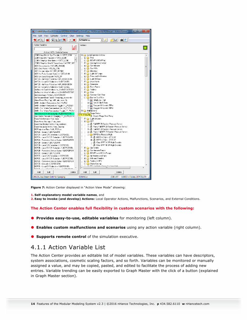
Figure 7: Action Center displayed in “Action View Mode” showing:
1. Self-explanatory model variable names, and 2. Easy to invoke (and develop) Actions: Local Operator Actions, Malfunctions, Scenarios, and External Conditions.
The Action Center enables full flexibility in custom scenarios with the following:
� Provides easy-to-use, editable variables for monitoring (left column).
� Enables custom malfunctions and scenarios using any action variable (right column).
� Supports remote control of the simulation executive.
4.1.1 Action Variable List The Action Center provides an editable list of model variables. These variables can have descriptors, system associations, cosmetic scaling factors, and so forth. Variables can be monitored or manually assigned a value, and may be copied, pasted, and edited to facilitate the process of adding new entries. Variable trending can be easily exported to Graph Master with the click of a button (explained in Graph Master section).
Features of the Modular Modeling System v2.3 | ©2016 nHance Technologies, Inc. p 434.582.6110 w nHancetech.com 15
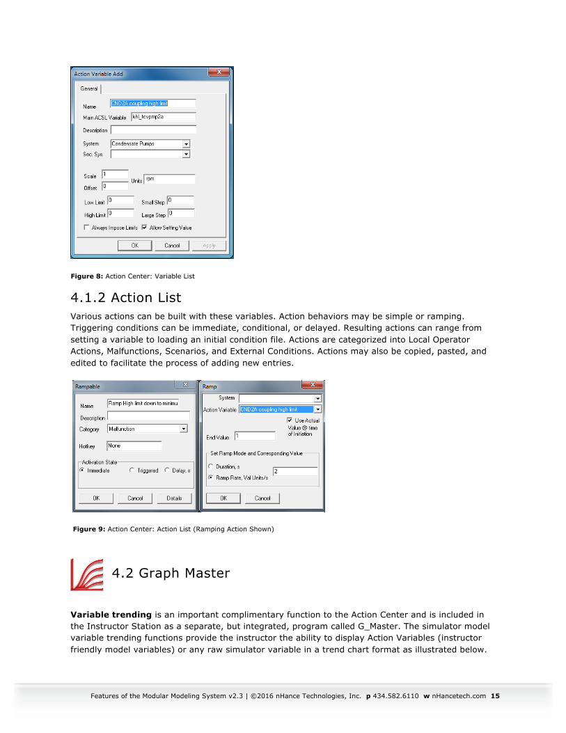
Figure 8: Action Center: Variable List
4.1.2 Action List Various actions can be built with these variables. Action behaviors may be simple or ramping. Triggering conditions can be immediate, conditional, or delayed. Resulting actions can range from setting a variable to loading an initial condition file. Actions are categorized into Local Operator Actions, Malfunctions, Scenarios, and External Conditions. Actions may also be copied, pasted, and edited to facilitate the process of adding new entries.
Figure 9: Action Center: Action List (Ramping Action Shown)
4.2 Graph Master
Variable trending is an important complimentary function to the Action Center and is included in the Instructor Station as a separate, but integrated, program called G_Master. The simulator model variable trending functions provide the instructor the ability to display Action Variables (instructor friendly model variables) or any raw simulator variable in a trend chart format as illustrated below.
16 Features of the Modular Modeling System v2.3 | ©2016 nHance Technologies, Inc. p 434.582.6110 w nHancetech.com
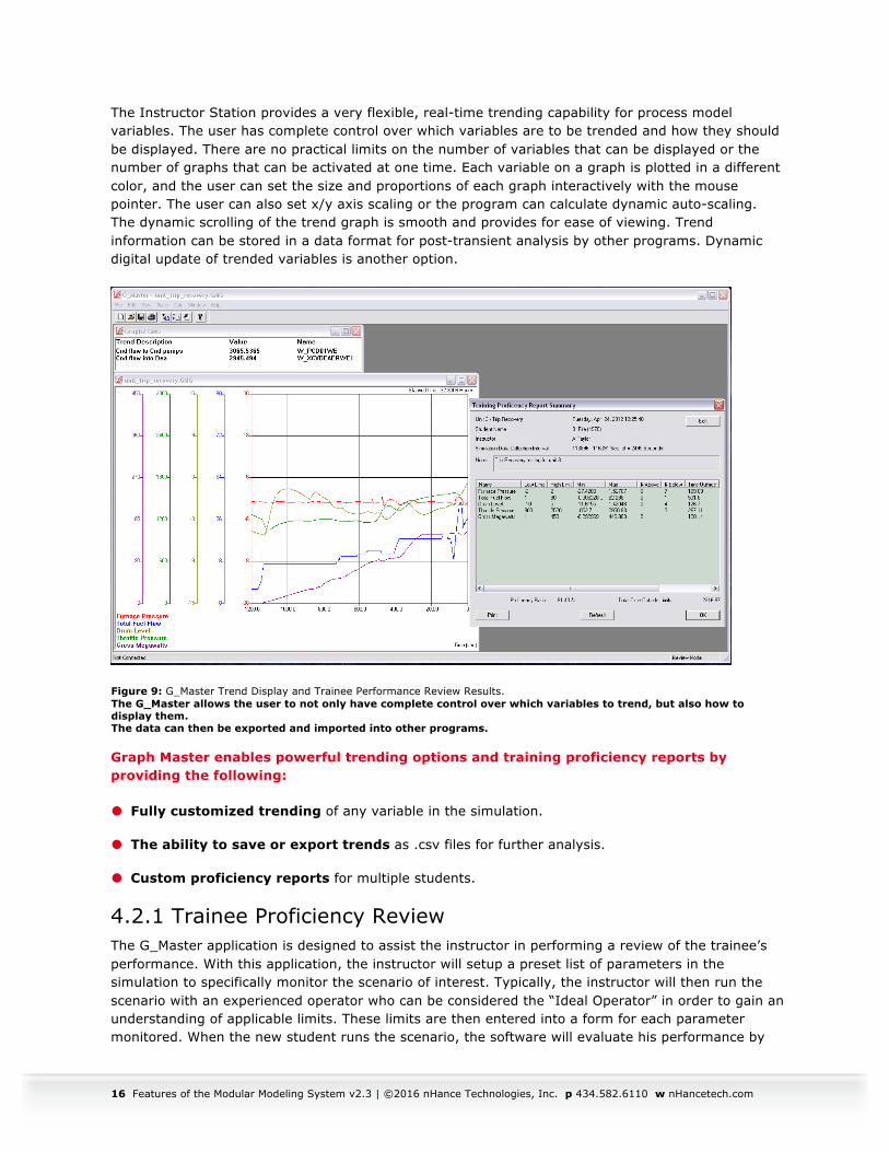
The Instructor Station provides a very flexible, real-time trending capability for process model variables. The user has complete control over which variables are to be trended and how they should be displayed. There are no practical limits on the number of variables that can be displayed or the number of graphs that can be activated at one time. Each variable on a graph is plotted in a different color, and the user can set the size and proportions of each graph interactively with the mouse pointer. The user can also set x/y axis scaling or the program can calculate dynamic auto-scaling. The dynamic scrolling of the trend graph is smooth and provides for ease of viewing. Trend information can be stored in a data format for post-transient analysis by other programs. Dynamic digital update of trended variables is another option.
Figure 9: G_Master Trend Display and Trainee Performance Review Results. The G_Master allows the user to not only have complete control over which variables to trend, but also how to display them. The data can then be exported and imported into other programs.
Graph Master enables powerful trending options and training proficiency reports by providing the following:
� Fully customized trending of any variable in the simulation.
� The ability to save or export trends as .csv files for further analysis.
� Custom proficiency reports for multiple students.
4.2.1 Trainee Proficiency Review The G_Master application is designed to assist the instructor in performing a review of the trainee’s performance. With this application, the instructor will setup a preset list of parameters in the simulation to specifically monitor the scenario of interest. Typically, the instructor will then run the scenario with an experienced operator who can be considered the “Ideal Operator” in order to gain an understanding of applicable limits. These limits are then entered into a form for each parameter monitored. When the new student runs the scenario, the software will evaluate his performance by
Features of the Modular Modeling System v2.3 | ©2016 nHance Technologies, Inc. p 434.582.6110 w nHancetech.com 17
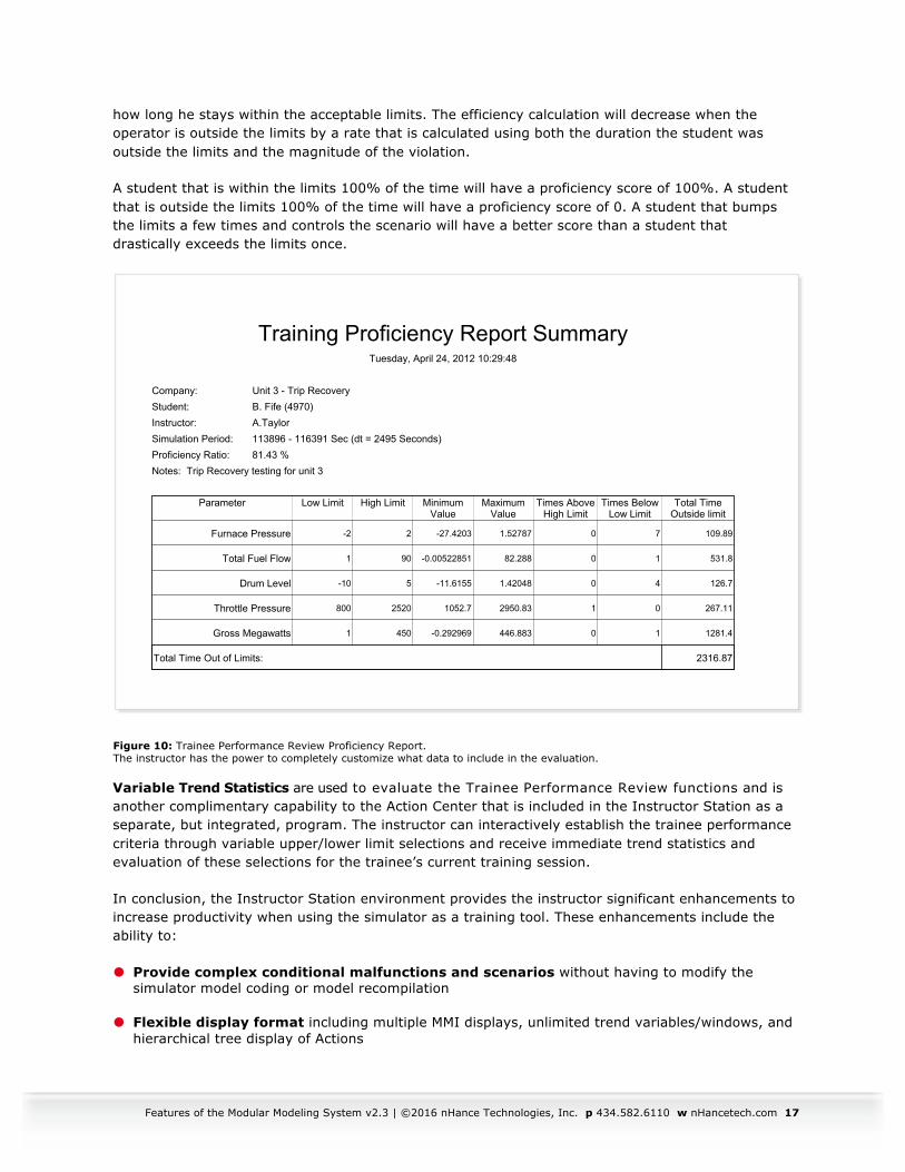
how long he stays within the acceptable limits. The efficiency calculation will decrease when the operator is outside the limits by a rate that is calculated using both the duration the student was outside the limits and the magnitude of the violation.
A student that is within the limits 100% of the time will have a proficiency score of 100%. A student that is outside the limits 100% of the time will have a proficiency score of 0. A student that bumps the limits a few times and controls the scenario will have a better score than a student that drastically exceeds the limits once.
Figure 10: Trainee Performance Review Proficiency Report. The instructor has the power to completely customize what data to include in the evaluation.
Variable Trend Statistics are used to evaluate the Trainee Performance Review functions and is another complimentary capability to the Action Center that is included in the Instructor Station as a separate, but integrated, program. The instructor can interactively establish the trainee performance criteria through variable upper/lower limit selections and receive immediate trend statistics and evaluation of these selections for the trainee’s current training session.
In conclusion, the Instructor Station environment provides the instructor significant enhancements to increase productivity when using the simulator as a training tool. These enhancements include the ability to:
� Provide complex conditional malfunctions and scenarios without having to modify the simulator model coding or model recompilation
� Flexible display format including multiple MMI displays, unlimited trend variables/windows, and hierarchical tree display of Actions
Training Proficiency Report SummaryTuesday, April 24, 2012 10:29:48
Company: Unit 3 - Trip RecoveryStudent: B. Fife (4970) Instructor: A.TaylorSimulation Period: 113896 - 116391 Sec (dt = 2495 Seconds)Proficiency Ratio: 81.43 %Notes: Trip Recovery testing for unit 3
Parameter Low Limit High Limit MinimumValue
MaximumValue
Times AboveHigh Limit
Times BelowLow Limit
Total TimeOutside limit
Furnace Pressure -2 2 -27.4203 1.52787 0 7 109.89
Total Fuel Flow 1 90 -0.00522851 82.288 0 1 531.8
Drum Level -10 5 -11.6155 1.42048 0 4 126.7
Throttle Pressure 800 2520 1052.7 2950.83 1 0 267.11
Gross Megawatts 1 450 -0.292969 446.883 0 1 1281.4
Total Time Out of Limits: 2316.87
18 Features of the Modular Modeling System v2.3 | ©2016 nHance Technologies, Inc. p 434.582.6110 w nHancetech.com
� Implementation of OPC standards permits merging the simulator model with third-party hardware/software for model control
5. Support 5.1 nHance Help System nHance Technologies is dedicated to providing the best user experience. Part of that process is documenting all modeling and simulation tools. All programs come with extensive help documentation detailing their usage. In addition, non-trial modules have thorough documentation describing the variables and first principles equations.
5.2 MMS Professionals Program nHance Technologies is committed to providing continuous support for all MMS users. Because each customer’s needs are unique, we have created the MMS Professionals Program, an annual subscription-based support plan, which provides:
� Complimentary copy of MMS CompGen with initial MMS license
� Free training at nHance Technologies’ facilities
� Future software upgrades and patches
� Extensive user assistance for MMS
� Discounts for additional engineering services
� Discounts for additional copies of MMS
This support is provided to customers as a corporate-based plan, not a per-copy basis.
5.3 Simulator Maintenance Plans nHance Technologies is devoted to supporting any in-house developed simulator post-delivery. We provide low cost, custom support plans per site, depending on customer needs. Customers are free to combine aspects of software maintenance, simulation management, or even simulator-to-plant synchronization.
Features of the Modular Modeling System v2.3 | ©2016 nHance Technologies, Inc. p 434.582.6110 w nHancetech.com 19
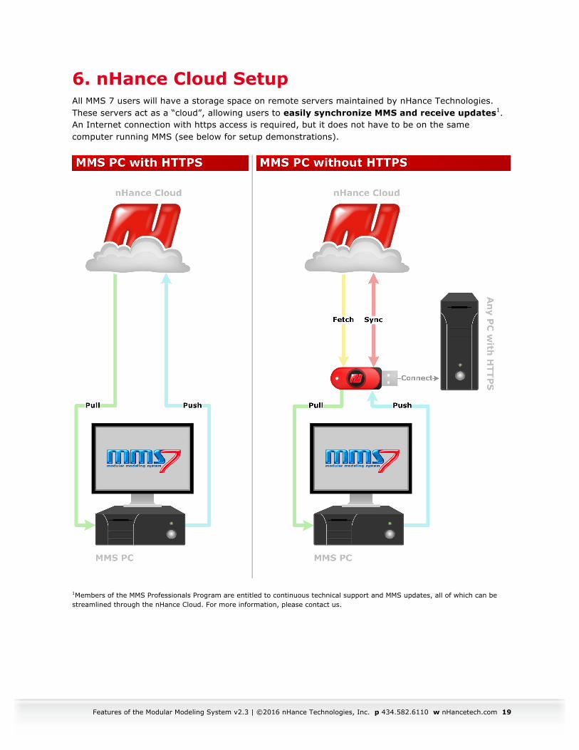
6. nHance Cloud Setup All MMS 7 users will have a storage space on remote servers maintained by nHance Technologies. These servers act as a “cloud”, allowing users to easily synchronize MMS and receive updates1. An Internet connection with https access is required, but it does not have to be on the same computer running MMS (see below for setup demonstrations).
1Members of the MMS Professionals Program are entitled to continuous technical support and MMS updates, all of which can be streamlined through the nHance Cloud. For more information, please contact us.