Embed Size (px)
Citation preview
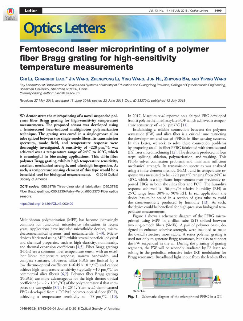
Femtosecond laser microprinting of a polymerfiber Bragg grating for high-sensitivitytemperature measurementsCHI LI, CHANGRUI LIAO,* JIA WANG, ZHENGYONG LI, YING WANG, JUN HE, ZHIYONG BAI, AND YIPING WANG
Key Laboratory of Optoelectronic Devices and Systems of Ministry of Education and Guangdong Province, College of Optoelectronic Engineering,Shenzhen University, Shenzhen 518060, China*Corresponding author: [email protected]
Received 27 May 2018; accepted 18 June 2018; posted 22 June 2018 (Doc. ID 332704); published 12 July 2018
We demonstrate the microprinting of a novel suspended pol-ymer fiber Bragg grating for high-sensitivity temperaturemeasurements. The proposed sensor was developed usinga femtosecond laser-induced multiphoton polymerizationtechnique. The grating was cured in a single-groove silicatube spliced between two single-mode fibers. Its transmissionspectrum, mode field, and temperature response werethoroughly investigated. A sensitivity of −220 pm∕°C wasachieved over a temperature range of 24°C to 40°C, whichis meaningful in biosensing applications. This all-in-fiberpolymer Bragg grating exhibits high temperature sensitivity,excellent mechanical strength, and ultrahigh integration. Assuch, a temperature sensing element of this type would be abeneficial tool for biological measurements. © 2018 OpticalSociety of America
OCIS codes: (050.6875) Three-dimensional fabrication; (060.3735)
Fiber Bragg gratings; (050.2230) Fabry-Perot; (060.2370) Fiber optics
sensors.
https://doi.org/10.1364/OL.43.003409
Multiphoton polymerization (MPP) has become increasinglycommon for functional microdevice fabrication in recentyears. Applications have included microfluidic devices, micro-electromechanical systems, and metamaterials [1–3]. Micro-devices fabricated using MPP exhibit several beneficial physicaland chemical properties, such as high elasticity, nonlinearity,and thermal expansion coefficients [4,5]. Fiber Bragg gratings(FBGs) are a common fiber temperature sensor with an excel-lent linear temperature response, narrow bandwidth, andcompact structure. However, silica FBGs are limited by alow thermo-optical coefficient (∼6.45 × 10⁻⁶∕°C) and cannotachieve high temperature sensitivity (typically ∼10 pm∕°C forcommercial silica fibers) [6,7]. Polymer fiber Bragg gratings(PFBGs) are more advantageous for the high thermo-opticalcoefficient (∼ − 2 × 10⁻⁴∕°C) of the polymer material that com-poses the waveguide [8,9]. In 2011, Yuan et al. demonstratedFBGs developed from a TOPAS polymer optical fiber (POF),achieving a temperature sensitivity of −78 pm∕°C [10].
In 2017, Marques et al. reported on a chirped FBG developedfrom a polymethyl methacrylate POF which achieved a temper-ature sensitivity of −131 pm∕°C [11].
Establishing a reliable connection between the polymerwaveguide (PW) and silica fiber is a critical issue restrictingthe development and use of PFBGs in fiber sensing systems.In this Letter, we seek to solve these connection problemsby proposing an all-in-fiber PFBG fabricated with femtosecond(FS) laser micromachining [12]. The device is produced in foursteps: splicing, ablation, polymerization, and washing. ThisPFBG solves connection problems and maintains sufficientmechanical strength. Its transmission spectrum was analyzedusing a finite element method (FEM), and its temperature re-sponse was measured to be −220 pm∕°C ranging from 24°C to40°C, which is a significant improvement over previously re-ported FBGs in both the silica fiber and POF. The humidityresponse achieved is −36 pm∕% relative humidity (RH) at25°C range from 30% to 90% RH. In real application, thedevice has to be sealed in a section of glass tube to avoidthe cross-sensitivity produced by humidity [13]. As such,the device could be beneficial for high-precision biological tem-perature measurements.
Figure 1 shows a schematic diagram of the PFBG micro-printed using MPP in a silica tube (ST) spliced betweentwo single-mode fibers (SMFs). A pair of polymer bases, de-signed to enhance cohesive strength, were included to makethe overall structure more stable. A series polymer grating isused not only to generate Bragg resonance, but also to supportthe PW suspended in the air. During the printing of gratingsegments, the PW will be secondly irradiated by FS laser, re-sulting in the periodical refractive index (RI) modulation forBragg resonance. Broadband light input from the lead-in fiber
Fig. 1. Schematic diagram of the microprinted PFBG in a ST.
Letter Vol. 43, No. 14 / 15 July 2018 / Optics Letters 3409
0146-9592/18/143409-04 Journal © 2018 Optical Society of America

was transmitted to the lead-out fiber through a rectangular PW.The input light was modulated by the polymer grating, produc-ing Bragg resonance in the spectrum. The microprinting tech-nique can be divided into four steps.
Step 1: As shown in Fig. 2(a), an ST with a length of800 μm and an internal/external diameter of 30/120 μmwas spliced between two SMFs. If the splicing current is toohigh, the ST air hole will collapse. If the current is too low,the mechanical strength of the splicing point will be weak.Optimized splicing parameters for a multimode fiber includeda splicing current of −10 bit for 400 ms (FUJIKURA 80 S fiberfusion splicer).
Step 2: As shown in Fig. 2(b), a pair of rectangular grooveswith a size of 800 μm × 40 μm × 65 μm was used to open theST air hole. They were drilled separately from the upper andlower ST surfaces using an FS laser. The sample was then care-fully cleaned with alcohol under ultrasonic conditions toremove residual debris generated by FS laser ablation.
Step 3: As shown in Fig. 2(c), ST grooves were filled with aphotosensitive resin (PR), resulting in a capillarity effect. ThePR used in this experiment was a type of negative resin (Type:PP-1, purchased from Zhichu optics Co., Ltd., Shenzhen,China), which contains photo-initiator (IGR-369, Ciba-Geigy)and monomer (SR444, SR369, from Sartomer) compounds.The sample was then mounted on a 3D air-bearing stage(Aerotech) for structure polymerization. The utilized FS laserhad a central wavelength of 1026 nm, a pulse width of 250 fs,and a repetition rate of 200 kHz. A pair of bases with dimen-sions of 800 μm × 10 μm × 11 μm was first polymerized alongthe inner ST surface to decrease the grating segment length andenhance cohesive strength between the ST and the polymerizedstructure. The PW and FBG segments were then polymerizedby an oil objective with a numerical aperture of 1.4.
Step 4: As shown in Fig. 2(d), the sample was immersed inan acetone and isopropyl alcohol mixture (1:5) for 20 min, towash away any remaining PR. After these four steps, the PFBGwas successfully microprinted in the ST and integrated in anall-fiber system.
The light-guiding properties of this polymerized waveguidewere experimentally investigated. First, the same laser, operat-ing at a power of 1.94 mW with a scanning velocity of200 μm/s, was employed to fabricate the PW and FBG.The FBG was polymerized using single scanning with a periodof 1035 nm, and the PW was polymerized using snake scan-ning to increase its cross-sectional width. Figures 3(a)–3(c)show a series of scanning electron microscope (SEM) imagesfor three samples with waveguide widths of 1810, 2360,
and 4680 nm before glass tube packing. The polymerized struc-ture is evident in the figure. It is also clear that there is no ad-hesion, and the waveguide flatness has improved with increasingwidth. The transmission spectra of these three samples was mea-sured using a broadband light source (1250–1650 nm) and anoptical spectrum analyzer, the results of which are shown inFig. 3(d). The insertion loss of this device decreased significantly(∼6 dB at 1550 nm), as the width increased from 1810 to4680 nm. This can be explained by improved modal radiimatching between the PW and each SMF. Additionally, the ap-parent interference spectrum can only be observed at 1810 nm,which we believe is the result of multimode interference pro-duced by a mode mismatch between the SMF and the PW [14].
As shown in Fig. 3(d), there is low Bragg reflection(∼1557 nm) present in this spectrum because the same laserpower was used to fabricate the PW and FBG. As such, themodulation intensity is not high enough to excite Bragg reso-nance [15,16]. The RI of the polymerized structures can beincreased by increasing the FS laser power [17]. Therefore,to enhance the modulation intensity, differing laser powersof 1.94 and 1.30 mW were utilized at the same velocity(200 μm/s) to fabricate the FBG and PW. To obtain a stablePW with an apparent Bragg resonance, we have explored theoptimal width of PW. When the PW width is similar to that ofthe SMF core, the Bragg resonance will be too weak to be ob-served. When the PW width is too small, its propagation losswill be significantly increased, and the multimode interferenceeffect will become very significant. After a number of compar-ative experiments, we got the best PWwidth of∼4.68 μm. Theresulting transmission and reflection spectrum of the polymer-ized FBG are shown in Fig. 4, where two transmission dips areobserved at 1558.5 (1.2 dB) and 1554.0 nm (0.5 dB), and onereflection peak is observed at 1558.5 nm (16.5 dB). As a result,this can be classified as a few-mode type PW [18].
A Fabry–Perot (F-P) interferometer was constructed in theSMF to calibrate material dispersion of the polymer. A sche-matic diagram of this system is included in the inset imageof Fig. 5. By the same method in Fig. 2, a PW with a lengthof 40 μm and a width of 10 μm was directly polymerized in agrooved SMF, which is drilled by an FS laser. The broadband
Fig. 2. (a) ST was spliced between two SMFs, and (b) a pair ofgrooves were drilled using a FS laser. (c) Polymer structure was thenmicroprinted in the ST using MPP. (d) Any PR remaining in the STwas cleaned using an acetone and isopropyl alcohol mixture.
Fig. 3. SEM images of three PFBGs with waveguide widths of(a) 1810, (b) 2360, and (c) 4680 nm. The transmission spectra forthe three PFBGs are shown in (d).
3410 Vol. 43, No. 14 / 15 July 2018 / Optics Letters Letter

light transmitted from the left SMF is reflected at the twointerfaces (R1 and R2), and the resulting interference can beobserved in the reflection. This process is shown in Fig. 5.The PW material RI can be calculated with Eq. (1) by meas-uring the free spectral range (FSR) of the F-P interference. Thiscan be expressed as
FSR � λ2
2nL, (1)
where λ is the wavelength, n is the RI of the PWmaterial, and Lis the length of the PW (40 μm). The RI of the PW materialwas calculated to be 1.543 (at 1507 nm), 1.538 (at 1528 nm),1.531 (at 1558 nm), 1.523 (at 1588 nm), and 1.518 (at1615 nm).
An FEM model was used to simulate modal propertiesfor the PW, using its calculated RI and measured size(4.67 μm × 5.33 μm). Figure 6(a) shows the simulated rela-tionship between the Bragg resonance wavelength and thegrating period. It was calculated from Eq. (2):
mλb � 2nΛ, (2)
where m is the order of the Bragg resonance, λb is the Braggresonance wavelength, n is the effective RI, and Λ is thegrating period. Figure 6(b) shows the measured transmissionspectrum. The wavelengths of the two dips are in excellentagreement with simulated results and correspond to theLP01 (1558.5 nm) and LP11 modes (1554.0 nm). The small
deviations may have resulted from errors in the measurement ofPW dimensions.
The humidity response of the PFBG was measured using acontrolled humidity chamber [19]. Before testing, the samplewas placed in a drying oven for 24 h (at 20% RH and 21°C).The humidity measurement was done at 25°C, and the Braggresonant dip (at 1558.5 nm) was used to monitor humiditychange. The chamber was programmed to increase the RHfrom 30% to 90% with a step of 10% RH. The time betweeneach RH step was 30 min, where 15 min was used to increasethe RH, and 15 min was left for stabilization. The humiditysensitivity achieved is −36 pm∕% RH with a standard errorof 2 pm, as shown in Fig. 7. In real temperature measurements,the cross-sensitivity from humidity can be overcome by a glasstube package [20].
The temperature response of the PFBG was measured usinga controllable furnace [21]. The Bragg resonant wavelength(∼1558.5 nm) was used to monitor temperature changes dur-ing the experiment. The temperature was gradually increasedfrom 24°C to 40°C with a step of 2°C and maintained for15 min during each step (at 50% RH). Figure 8(a) demon-strates the spectral evolution of transmitted light, as the ambi-ent temperature was increased. The blue shift in the Bragg
Fig. 4. Transmission and reflection spectrum for the PFBG.
Fig. 5. Reflection spectrum for the PW-based F-P interferometer.The inset image shows a schematic diagram of this F-P interferometer.
Fig. 6. (a) Simulated relationship between a Bragg resonance wave-length and grating period. (b) Measured transmission spectrum andsimulated mode field (LP01 and LP11) for the two dips.
Fig. 7. Bragg wavelength shift evolution of the PFBG as the RHincreased from 30% to 90%.
Letter Vol. 43, No. 14 / 15 July 2018 / Optics Letters 3411

resonant wavelength is clearly evident in this process. Theattenuation of the sensor system is getting higher which canbe the result of the reduced RI of polymer as temperature rises.Figure 8(b) illustrates the linear fitting of the Bragg resonantwavelength with temperature changes, achieving a sensitivityof −220 pm∕°C with a standard error of 2 pm. This is 20 timeshigher than that of pure silica FBG and higher than previousreports on Bragg gratings in a POF [22]. The glass transitiontemperature (T g ) of the used resin is ∼100°C, which is dem-onstrated in the Sartomer product manual. Experimentally, themaximum operating temperature of this device is found to be80°C. This enhanced temperature sensitivity can be explainedby the high thermo-optical coefficient of the utilized polymerand completely suspended polymer structure.
In conclusion, we have demonstrated an all-in-fiber PFBGwhich was microprinted by an FS laser-induced MPP. ThisPFBG is composed of a base, a PW, and a FBG. The useof optimized laser power produces an obvious Bragg resonancein the transmission spectrum. A polymer F-P interferometerwas fabricated in the SMF to calibrate PW material dispersion,and PW modal properties were simulated using FEM. Thesesimulated results were in excellent agreement with the experi-ment and confirmed that the microprinted PW is a few-mode
fiber with two transmission dips corresponding to the LP01and LP11 modes. The RH response achieved is −36 pm∕%RH. In real application, the cross-sensitivity produced by hu-midity can be solved by a glass tube package. Finally, a linearPFBG thermal response was achieved with a high sensitivity of−220 pm∕°C. This FS laser-induced MPP could be a powerfulnew tool in the field of all-in-fiber devices and systems. Thismethod is easy to be achieve and low in cost in real application.
Funding. National Natural Science Foundation of China(NSFC) (61575128, 61425007, 61635007); Natural ScienceFoundation of Guangdong Province (2015A030313541,2015B010105007, 2014A030308007); Science andTechnology Innovation Commission of Shenzhen(KQJSCX20170727101953680, JCYJ20160520163134575,JCYJ20160523113602609, JCYJ20160307143501276);Development and Reform Commission of ShenzhenMunicipality Foundation.
REFERENCES
1. Y. L. Li, Y. F. Fang, J. Wang, L. Wang, and S. W. Tang, Lab Chip 16,4406 (2016).
2. D. Dendukuri, D. C. Pregibon, J. Collins, and T. A. Hatton, Nat. Mater.5, 365 (2006).
3. Y. F. Chen, J. R. Tao, and Z. Cui, Microelectron. Eng. 78-79, 612(2005).
4. H. Zou, S. S. Wu, and J. Shen, Chem. Rev. 108, 3893 (2008).5. J. A. Delaire and K. Nakatani, Chem. Rev. 100, 1817 (2000).6. M. Majumder, T. K. Gangopadhyay, A. K. Chakraborty, and K.
Dasgupta, Sens. Actuators A 147, 150 (2008).7. D. Grobnic, S. J. Mihailov, J. Ballato, and P. D. Dragic, Optica 2, 313
(2015).8. C. Markos, A. Stefani, K. Nielsen, and H. K. Rasmussen, Opt. Express
21, 4758 (2013).9. G. Woyessa, A. Fasano, C. Markos, H. Rasmussen, and O. Bang,
IEEE Photon. Technol. Lett. 29, 575 (2017).10. W. Yuan, L. Khan, and D. J. Webb, Opt. Express 19, 1971 (2011).11. C. A. F. Marques, P. Antunes, P. Mergo, and D. J. Webb, IEEE
Photon. Technol. Lett. 29, 500 (2017).12. W. Xiong, Y. S. Zhou, X. N. He, Y. Gao, and M. Mahjouri-Samani,
Light Sci. Appl. 1, e6 (2012).13. G. Woyessa, J. K. M. Pedersen, A. Fasano, K. Nielsen, C. Markos,
and O. Bang, Opt. Lett. 42, 1161 (2017).14. P. F. Wang, G. Brambilla, M. Ding, Y. Semenova, Q. Wu, and G.
Farrell, Opt. Lett. 36, 2233 (2011).15. K. K. Lee, A. Mariampillai, M. Haque, B. A. Standish, V. X. Yang, and
P. R. Herman, Opt. Express 21, 24076 (2013).16. J. R. Grenier, L. A. Fernandes, and P. R. Herman, Opt. Express 21,
4493 (2013).17. T. Gissibl, S. Wanger, M. Schmid, and H. Giessen, Opt. Mater.
Express 7, 2293 (2017).18. X. H. Feng, H. Y. Tam, and W. H. Chung, Opt. Commun. 263, 295
(2006).19. G. Woyessa, A. Fasano, C. Markos, and A. Stefani, Opt. Mater.
Express 7, 286 (2017).20. Z. Y. Li, C. R. Liao, J. Song, Y. Wang, and F. Zhu, Photon. Res. 4, 197
(2016).21. Z. Zhang, C. R. Liao, J. Tang, Y. Wang, Z. Y. Bai, and Z. Y. Li, IEEE
Photon. J. 9, 7101109 (2017).22. W. Yuan and A. Stefani, IEEE Photon. Technol. Lett. 24, 401 (2012).
Fig. 8. (a) Spectral transmission evolution of the PFBG as thetemperature increased from 24°C to 40°C. (b) Dip wavelength versustemperature.
3412 Vol. 43, No. 14 / 15 July 2018 / Optics Letters Letter