Embed Size (px)
Citation preview

FIGURE 1. OPERATOR CONTROLS
S/N 791000 and Above
ITEM PART UNITS PER NO. NO. DESCRIPTION MACHINE
1 31440023 . LOGIC BOX ASSEMBLY.............................. 1 2A 20292874 . . BOX, LH Control (Box Only) ....................... 1 2B* 20292887 . . BOX, RH Control......................................... 1 3* 27260500 . COVER, Logic Box ....................................... 1 4 87128945 . CORD, Pusher Plate Assembly .................... 2 5 44050402 . HOOK, Pusher Plate Cord Snap................... 4 6 38550011 . SPRING, Cord Support Whip........................ 2 8 24587904 . CLAMP, Wiring Cable #8 .............................. 4 9 2774281 . CAPSCREW, Hex Head ¼-20 x 1 ................ 4
ITEM PART
NO. NO. DESCRIPTION MACHINE 11 3042013 . LOCKNUT, Hex ¼-20.................................... 4 12 82633984 . TUBE, Cord Support...................................... 4 13 14345000 . U-BAR, Plate Pusher Cord ............................ 2 14 96790134 . PUSHER, Plate (See Sheet 79C-01-1) ......... 2 15* 50270225 . MOUNT, Logic Box Vibration ........................ 4
Part of 9879 0015, Remote Plate Pusher Kit (Whip Style)
JAN/09 *Not Illustrated 79C-1, Rev. B, Page 1

FIGURE 1A-1. PLATE PUSHER for 63-Inch Wide Gauge and Trapezoid Plates
S/N 791000 and Above
MAY/2012 *Not Illustrated 79C-01A-1, Rev. A, Page 1
ITEM PART UNITS PER NO. NO. DESCRIPTION MACHINE
-- 96790134 PLATE PUSHER ASSEMBLY ..................... 2 1 81470004 . WELDMENT, Plate Pusher ........................ 1 2 27230195 . COVER, Box .............................................. 1 3 3064455 . LOCKWASHER, #8 ................................... 4 4 2849469 . SCREW, Pan Head Machine #8-32 x 3/8 .. 4 6 5125426 . SWITCH, Rocker ....................................... 1 7 4598989 . GRIP, Handle ............................................. 1 8 96790120 . CONNECTING WIRING ASSEMBLY ........ 1 9 5120729 . . PLUG, Panel ............................................ 1 10 78891450 . SWITCH, Push Button ............................... 2 11 84316002 . . BOOT, Sealing ......................................... 2 12 2837217 . SCREW, Round Head #4-40 ..................... 4 13 3064446 . LOCKWASHER, #4-40 .............................. 4 14 3048022 . NUT, Hex #4-40 ......................................... 4 15 56405039 . PLAQUE ..................................................... 1 16 2774301 . CAPSCREW, Hex Head 1/4 x 1-1/2 .......... 2 17 3064464 . LOCKWASHER, 1/4 .................................. 2 18 3001011 . NUT, Hex 1/4-20 ........................................ 2 19A 20981641 . GUIDE, Plate .............................................. 2 19B 20981642 . GUIDE, Trapezoid Plate (Opt. Not Shown) 2 20 2774771 . CAPSCREW, Hex Head 3/8 x 3/4 ............. 2 21 3020046 . NUT, Square 3/8-16 ................................... 2 22 42017987 . HANDLE, Guide ......................................... 1 23 3050079 . NUT, Wing M6 ........................................... 1 24 3721565 . CAPSCREW M6 x 45 ................................ 1 25 81470005 . HEAD, Plate Pusher ................................... 1 26A 96790106 CONNECTOR ASSEMBLY, Right Hand ...... 1 26B 96790107 CONNECTOR ASSEMBLY, Left Hand ........ 1 27 87128945 CONTROL CABLE ASSEMBLY .................. 2 28 21425570 BRACKET, Plate Pusher Support ................ 4 29 2774821 CAPSCREW, Hex Head 3/8-16 x 2 ............. 4 30 3042019 LOCKNUT, Hex 3/8-16 ................................ 4

FIGURE 2A-1B. AXLE for 63" Wide Gauge Machines
S/N 791000 and Above
MAR/2012 This part sheet has multiple pages 79C-2A-1B, Page 1 of 2
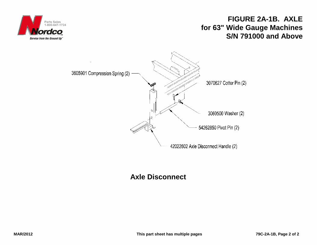
FIGURE 2A-1B. AXLE for 63" Wide Gauge Machines
S/N 791000 and Above
MAR/2012 This part sheet has multiple pages 79C-2A-1B, Page 2 of 2
Axle Disconnect

FIGURE 2-2. AXLE Chain Tensioner
S/N 791000 and Above
JULY/04 *Not Illustrated 79C-02-2, Page 1
ITEM NO. NO. DESCRIPTION MACHINE
-- 9879 0165 KIT, Chain Tensioner ............................... 1 1 4765 4830 . ARM, Lever ............................................ 1 2 5528 0050 . PLATE, Adjustment ................................ 1 3 1317 7454 . LEVER, Arm ........................................... 1 4 5528 0051 . PLATE, Adjusting Screw ........................ 1 5 7510 1400 . SPROCKET, Idler................................... 1 6 7658 0500 . SHAFT, Idler........................................... 1 7 1371 0350 . BRACKET, Pivot Mounting..................... 1 8 2947 886 . SETSCREW, Square Head 5/8-11 x 5... 1 9 3004 041 . NUT, Hex Jam 5/8-11............................. 1 10 5423 6625 . PIN, Pivot ............................................... 1 11 3301 240 . PIN, Clevis 3/8 x 1-1/4............................ 1 12 3060 470 . WASHER, SAE 3/8 ................................ 2 13 3060 037 . WASHER, Wrought ½ ............................ 7 14 3060 488 . WASHER, SAE ¾ .................................. 1 15 3070 319 . PIN, Cotter 1/8 x 1-1/2............................ 3 16 3070 467 . PIN, Cotter 5/32 x 1................................ 1 17 3001 031 . NUT, Hex ½-13 ...................................... 1 18 3001 041 . NUT, Hex 5/8-11 .................................... 1 19 3060 482 . WASHER, SAE 5/8 ................................ 1

FIGURE 3. BRAKES Parking Brake
S/N 791000 and Above
JULY/04 *Not Illustrated 79C-3, Page 1
ITEM NO. NO. DESCRIPTION MACHINE
-- 9879 0013 KIT, PARKING BRAKE ................................. 1 1 2136 8086 . BRACKET, Brake Mounting ........................ 1 2 4771 3220 . LEVER, Brake ............................................. 1 3 1896 1020 . RING, Clamp ............................................... 1 4 3301 881 . PIN, Clevis, 1 x 4 ......................................... 2 5 2782 519 . CAPSCREW, Socket Head 5/16 x 5/8 ........ 4 6 7090 0072 . SHOE, Lined Brake ..................................... 1 7 R0215106 . CLAMP, Push .............................................. 1 8 3025 021 . NUT, Hex 3/8-16.......................................... 1 9 3070 623 . PIN, Cotter 3/16 x 1-1/2 ............................... 2
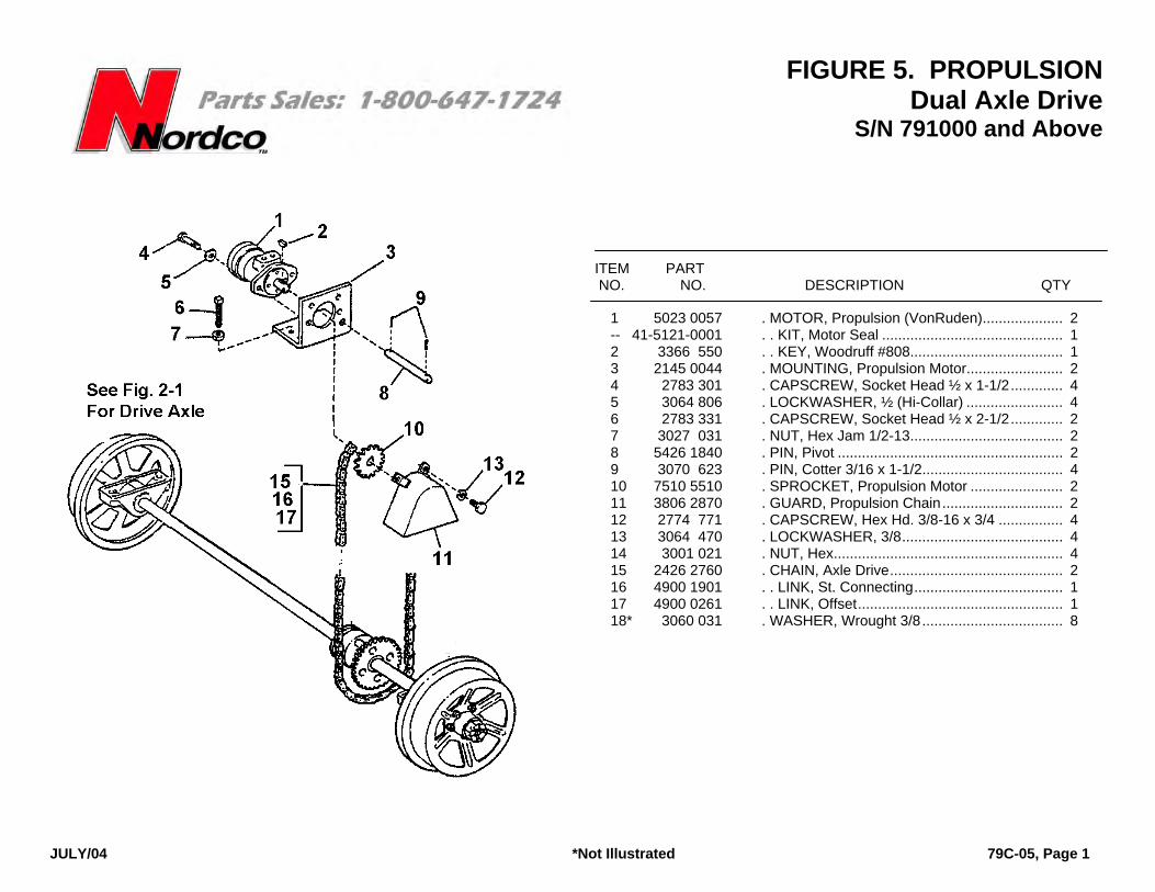
FIGURE 5. PROPULSION Dual Axle Drive
S/N 791000 and Above
JULY/04 *Not Illustrated 79C-05, Page 1
ITEM PART NO. NO. DESCRIPTION QTY
1 5023 0057 . MOTOR, Propulsion (VonRuden).................... 2 -- 41-5121-0001 . . KIT, Motor Seal ............................................. 1 2 3366 550 . . KEY, Woodruff #808...................................... 1 3 2145 0044 . MOUNTING, Propulsion Motor........................ 2 4 2783 301 . CAPSCREW, Socket Head ½ x 1-1/2............. 4 5 3064 806 . LOCKWASHER, ½ (Hi-Collar) ........................ 4 6 2783 331 . CAPSCREW, Socket Head ½ x 2-1/2............. 2 7 3027 031 . NUT, Hex Jam 1/2-13...................................... 2 8 5426 1840 . PIN, Pivot ........................................................ 2 9 3070 623 . PIN, Cotter 3/16 x 1-1/2................................... 4 10 7510 5510 . SPROCKET, Propulsion Motor ....................... 2 11 3806 2870 . GUARD, Propulsion Chain.............................. 2 12 2774 771 . CAPSCREW, Hex Hd. 3/8-16 x 3/4 ................ 4 13 3064 470 . LOCKWASHER, 3/8........................................ 4 14 3001 021 . NUT, Hex......................................................... 4 15 2426 2760 . CHAIN, Axle Drive........................................... 2 16 4900 1901 . . LINK, St. Connecting..................................... 1 17 4900 0261 . . LINK, Offset................................................... 1 18* 3060 031 . WASHER, Wrought 3/8................................... 8
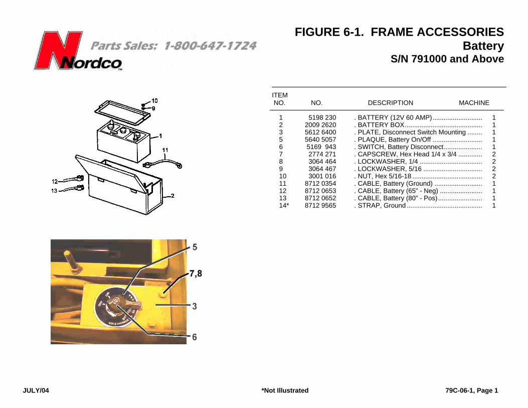
FIGURE 6-1. FRAME ACCESSORIES Battery
S/N 791000 and Above
JULY/04 *Not Illustrated 79C-06-1, Page 1
ITEM NO. NO. DESCRIPTION MACHINE
1 5198 230 . BATTERY (12V 60 AMP)........................... 1 2 2009 2620 . BATTERY BOX.......................................... 1 3 5612 6400 . PLATE, Disconnect Switch Mounting ........ 1 5 5640 5057 . PLAQUE, Battery On/Off ........................... 1 6 5169 943 . SWITCH, Battery Disconnect..................... 1 7 2774 271 . CAPSCREW, Hex Head 1/4 x 3/4 ............. 2 8 3064 464 . LOCKWASHER, 1/4 .................................. 2 9 3064 467 . LOCKWASHER, 5/16 ................................ 2 10 3001 016 . NUT, Hex 5/16-18 ...................................... 2 11 8712 0354 . CABLE, Battery (Ground) .......................... 1 12 8712 0653 . CABLE, Battery (65” - Neg) ....................... 1 13 8712 0652 . CABLE, Battery (80” - Pos)........................ 1 14* 8712 9565 . STRAP, Ground ......................................... 1
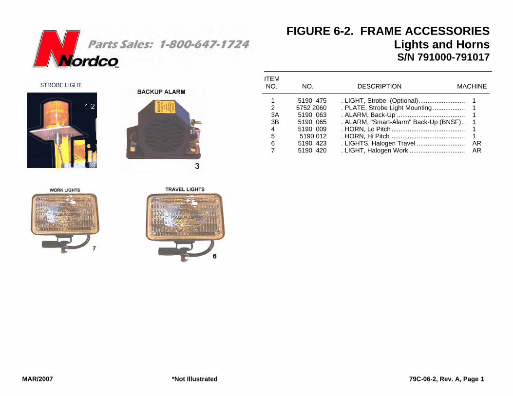
FIGURE 6-2. FRAME ACCESSORIES Lights and Horns S/N 791000-791017
MAR/2007 *Not Illustrated 79C-06-2, Rev. A, Page 1
ITEM NO. NO. DESCRIPTION MACHINE
1 5190 475 . LIGHT, Strobe (Optional).......................... 1 2 5752 2060 . PLATE, Strobe Light Mounting .................. 1 3A 5190 063 . ALARM, Back-Up ...................................... 1 3B 5190 065 . ALARM, "Smart-Alarm" Back-Up (BNSF).. 1 4 5190 009 . HORN, Lo Pitch ......................................... 1 5 5190 012 . HORN, Hi Pitch ......................................... 1 6 5190 423 . LIGHTS, Halogen Travel ........................... AR 7 5190 420 . LIGHT, Halogen Work ............................... AR
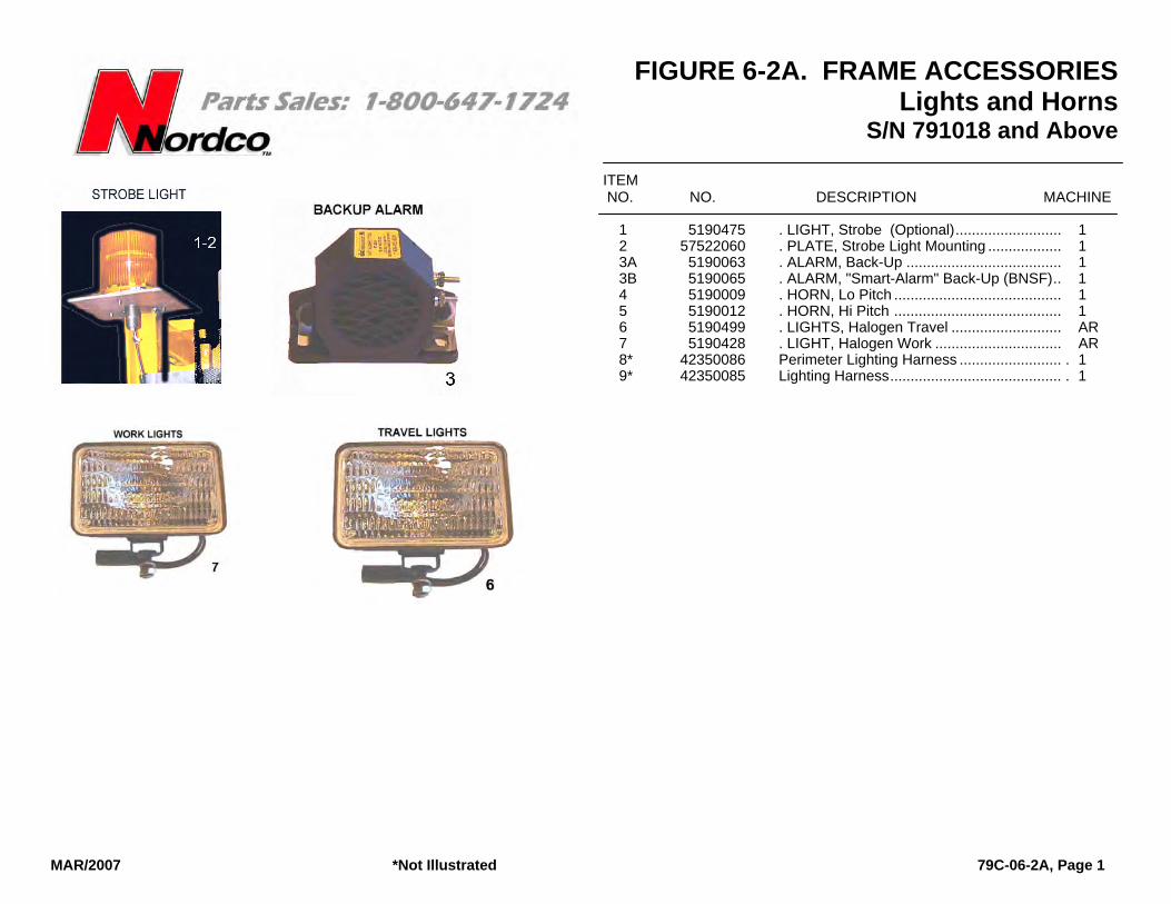
FIGURE 6-2A. FRAME ACCESSORIES Lights and Horns
S/N 791018 and Above
MAR/2007 *Not Illustrated 79C-06-2A, Page 1
ITEM NO. NO. DESCRIPTION MACHINE
1 5190475 . LIGHT, Strobe (Optional).......................... 1 2 57522060 . PLATE, Strobe Light Mounting .................. 1 3A 5190063 . ALARM, Back-Up ...................................... 1 3B 5190065 . ALARM, "Smart-Alarm" Back-Up (BNSF).. 1 4 5190009 . HORN, Lo Pitch ......................................... 1 5 5190012 . HORN, Hi Pitch ......................................... 1 6 5190499 . LIGHTS, Halogen Travel ........................... AR 7 5190428 . LIGHT, Halogen Work ............................... AR 8* 42350086 Perimeter Lighting Harness ......................... . 1 9* 42350085 Lighting Harness.......................................... . 1
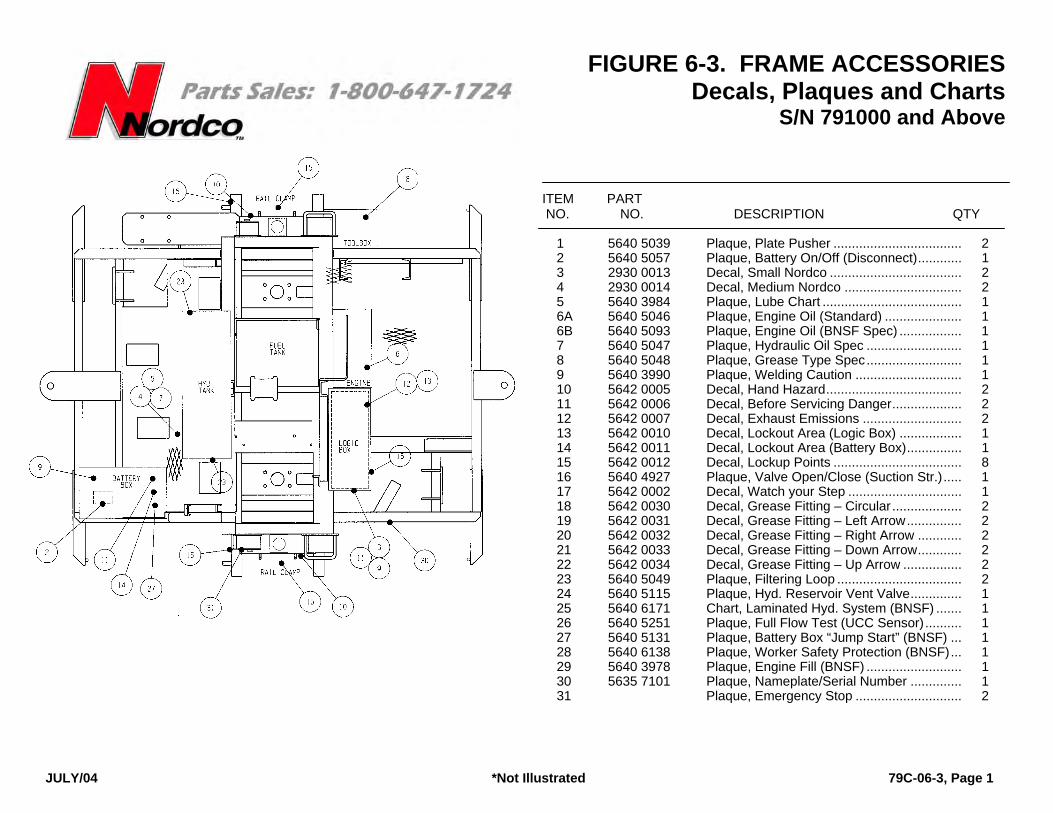
FIGURE 6-3. FRAME ACCESSORIES Decals, Plaques and Charts
S/N 791000 and Above
JULY/04 *Not Illustrated 79C-06-3, Page 1
ITEM PART NO. NO. DESCRIPTION QTY
1 5640 5039 Plaque, Plate Pusher ................................... 2 2 5640 5057 Plaque, Battery On/Off (Disconnect)............ 1 3 2930 0013 Decal, Small Nordco .................................... 2 4 2930 0014 Decal, Medium Nordco ................................ 2 5 5640 3984 Plaque, Lube Chart ...................................... 1 6A 5640 5046 Plaque, Engine Oil (Standard) ..................... 1 6B 5640 5093 Plaque, Engine Oil (BNSF Spec) ................. 1 7 5640 5047 Plaque, Hydraulic Oil Spec .......................... 1 8 5640 5048 Plaque, Grease Type Spec.......................... 1 9 5640 3990 Plaque, Welding Caution ............................. 1 10 5642 0005 Decal, Hand Hazard..................................... 2 11 5642 0006 Decal, Before Servicing Danger................... 2 12 5642 0007 Decal, Exhaust Emissions ........................... 2 13 5642 0010 Decal, Lockout Area (Logic Box) ................. 1 14 5642 0011 Decal, Lockout Area (Battery Box)............... 1 15 5642 0012 Decal, Lockup Points ................................... 8 16 5640 4927 Plaque, Valve Open/Close (Suction Str.)..... 1 17 5642 0002 Decal, Watch your Step ............................... 1 18 5642 0030 Decal, Grease Fitting – Circular ................... 2 19 5642 0031 Decal, Grease Fitting – Left Arrow............... 2 20 5642 0032 Decal, Grease Fitting – Right Arrow ............ 2 21 5642 0033 Decal, Grease Fitting – Down Arrow............ 2 22 5642 0034 Decal, Grease Fitting – Up Arrow ................ 2 23 5640 5049 Plaque, Filtering Loop .................................. 2 24 5640 5115 Plaque, Hyd. Reservoir Vent Valve.............. 1 25 5640 6171 Chart, Laminated Hyd. System (BNSF) ....... 1 26 5640 5251 Plaque, Full Flow Test (UCC Sensor).......... 1 27 5640 5131 Plaque, Battery Box “Jump Start” (BNSF) ... 1 28 5640 6138 Plaque, Worker Safety Protection (BNSF)... 1 29 5640 3978 Plaque, Engine Fill (BNSF) .......................... 1 30 5635 7101 Plaque, Nameplate/Serial Number .............. 1 31 Plaque, Emergency Stop ............................. 2

FIGURE 6-4. FRAME ACCESSORIES Optional Jackstands and Rail Sweeps
S/N 791000 and Above
FIGURE 6-4. FRAME ACCESSORIES Optional Jackstands and Rail Sweeps
S/N 791000 and Above
OCT/09 (ECO600123) 79C-6-4, Rev. B, Page 1
OCT/09 (ECO600123) 79C-6-4, Rev. B, Page 1
FIGURE 6-5. FRAME ACCESSORIES MISCELLANEOUS/OPTIONAL
S/N 791000 and Above
JULY/04 *Not Illustrated 79C-06-5, Page 1
ITEM PART UNITS PER NO. NO. DESCRIPTION MACHINE
1A 4083 100 VISE, 5-Inch................................................... 1 1B 4083 106 VISE, 6-Inch................................................... 1 2A 7580 092 EXTINGUISHER, Fire 20# (Standard)........... 1 2B 7580 097 EXTINGUISHER, Fire 20# (BNSF Spec)....... 1 2C 7580 098 EXTINGUISHER, Fire 20# (UPRR Spec) ...... 1 3A 2047 0027 BOX, Manual Storage (Standard) .................. 1 3B 2047 0026 BOX, Manual Storage (BNSF Spec).............. 1 4A 2047 0002 BOX, Tool (Small) .......................................... 1 5 5364 7796 PIN, Locking Hitch ......................................... 2 6 7581 010 KIT, First Aid (10 Person) .............................. 1

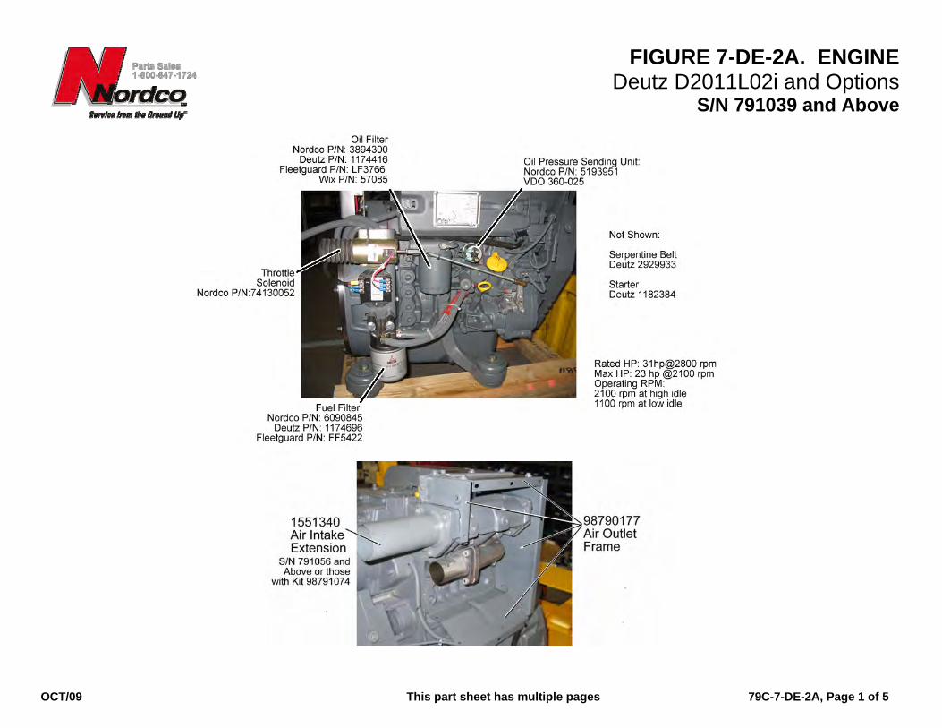
FIGURE 7-DE-2A. ENGINE Deutz D2011L02i and Options
S/N 791039 and Above
OCT/09 This part sheet has multiple pages 79C-7-DE-2A, Page 1 of 5
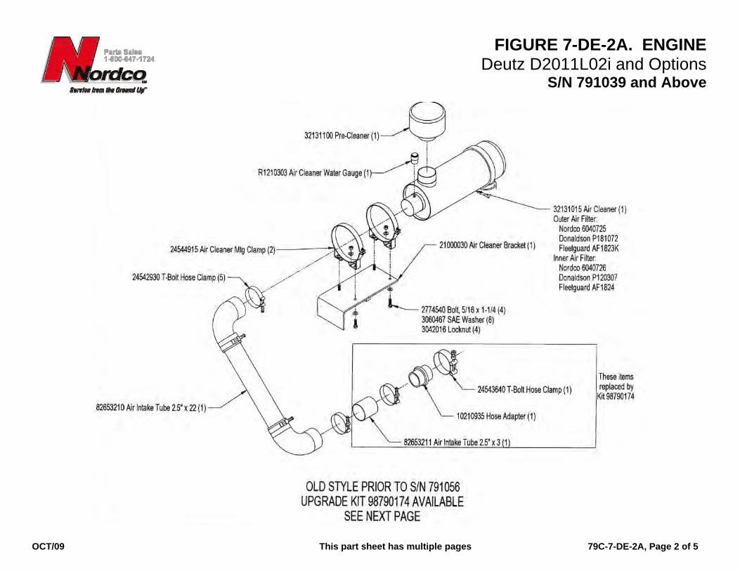
FIGURE 7-DE-2A. ENGINE Deutz D2011L02i and Options
S/N 791039 and Above
OCT/09 This part sheet has multiple pages 79C-7-DE-2A, Page 2 of 5

FIGURE 7-DE-2A. ENGINE Deutz D2011L02i and Options
S/N 791039 and Above
OCT/09 This part sheet has multiple pages 79C-7-DE-2A, Page 3 of 5

FIGURE 7-DE-2A. ENGINE Deutz D2011L02i and Options
S/N 791039 and Above
OCT/09 This part sheet has multiple pages 79C-7-DE-2A, Page 4 of 5

FIGURE 7-DE-2A. ENGINE Deutz D2011L02i and Options
S/N 791039 and Above
OCT/09 This part sheet has multiple pages 79C-7-DE-2A, Page 5 of 5
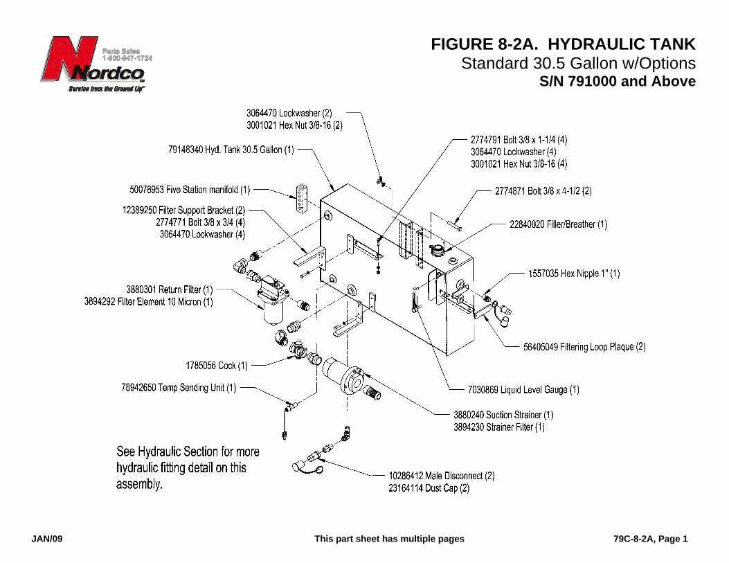
FIGURE 8-2A. HYDRAULIC TANK Standard 30.5 Gallon w/Options
S/N 791000 and Above
JAN/09 This part sheet has multiple pages 79C-8-2A, Page 1

FIGURE 8-2A. HYDRAULIC TANK Standard 30.5 Gallon w/Options
S/N 791000 and Above
JAN/09 This part sheet has multiple pages 79C-8-2A, Page 2

FIGURE 9-1A. OIL COOLER 63-Inch Wide Gauge Machines Only
S/N 791000 and Above
MAR/2012 79C-9-1A, Page 1 of 1

FIGURE 10-2. FUEL TANK Optional 18 Gallon
S/N 791000 and Above
JAN/09 79C-10-2, Rev. A, Page 1
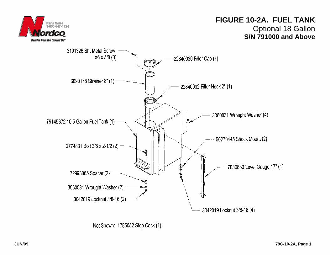
FIGURE 10-2A. FUEL TANK Optional 18 Gallon
S/N 791000 and Above
JUN/09 79C-10-2A, Page 1

FIGURE 13-1. RAIL LIFT S/N 791000 and Above
OCT/2005 *Not Illustrated 79C-13-1, Rev. A, Page 1

FIGURE 13-1. RAIL LIFT S/N 791000 and Above
OCT/2005 *Not Illustrated 79C-13-1, Rev. A, Page 2
ITEM PART UNITS PER NO. NO. DESCRIPTION MACHINE
1A 28552434 . CYLINDER, Lift (2.5” Bore)......................... 2 -- 96790084 . . Seal Kit ...................................................... 1 1B 28552671 . CYLINDER, Lift (3.0” Bore).......................... 2 -- 98790014 . . Seal Kit ...................................................... 1 2 2775321 . CAPSCREW, Hex Hd. 1/2-13 x 2................ 8 3 3001031 . NUT, Hex 1/2-13.......................................... 10 4 15138889 . BASE, Lift Cylinder ...................................... 2 5 2775351 . CAPSCREW, Hex Hd. 1/2-13 x 3-1/2.......... 2 6 3042025 . LOCKNUT, Hex 1/2-13 ................................ 2 -- 96790152 RAIL LIFT LIMIT SWITCH ASSEMBLY ........ NP 7 21446104 . PLATE, Limit Switch Mounting .................... 2 8 2774531 . CAPSCREW, Hex Hd. 5/16-18 x 1.............. 12 9 3064467 . LOCKWASHER, 5/16 .................................. 12 10 3001016 . NUT, Hex 5/16-18........................................ 8 11 82646000 . TUBE, Actuator............................................ 2 12 3303070 . PIN, Clevis ................................................... 2 13 82641000 . TUBE, Adjusting .......................................... 2 16 13220621 . GUIDE, Top ................................................. 2 17 13220716 . GUIDE, Bottom............................................ 2 18 3060467 . WASHER, SAE 5/16.................................... 8 19 2774801 . CAPSCREW, 3/8 x 1-1/2 ............................. 8 20 2774291 . CAPSCREW, 1/4 x 1-1/4 ............................. 4 21 3064464 . LOCKWASHER, 1/4 .................................... 4 22 3001011 . NUT, Hex 1/4-20.......................................... 4 24 54248299 . PIN, Cylinder Lock (w/roll pin) ..................... 2 25 5127236 . SWITCH, Limit ........................................... 4
Item 1A has been discontinued. Please order item 1B in its place. Seal kit for 1A is still available for purchase.
ITEM PART UNITS PER NO. NO. DESCRIPTION MACHINE
26 47651455 . LEVER, Limit Switch ................................... 4 27 2837658 . SCREW, Machine #10 x 2........................... 12 28 3064458 . LOCKWASHER, #10................................... 12 30 3064476 . LOCKWASHER, 1/2.................................... 8 31 3064470 . LOCKWASHER, 3/8.................................... 834 13080400 . COVER, Bottom Guide................................ 2 35 67267000 . SCREW, Adjusting ...................................... 2 36 13340700 . INSERT, Actuator Tube............................... 2 37 3042019 . LOCKNUT, 3/8-16 ....................................... 2 38 3007021 . NUT, Slotted Hex 3/8-16 ............................. 2 39 3060470 . WASHER, Wrought 3/8 ............................... 8 40 3070159 . PIN, Cotter................................................... 2 41 3074220 . COTTER, Hairpin ........................................ 2 42 3060464 . WASHER, SAE ¼ ....................................... 2
Item 26 is mounted 180 degrees from that shown.
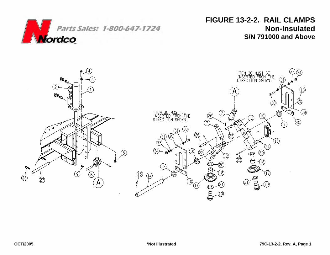
FIGURE 13-2-2. RAIL CLAMPS Non-Insulated
S/N 791000 and Above
OCT/2005 *Not Illustrated 79C-13-2-2, Rev. A, Page 1

FIGURE 13-2-2. RAIL CLAMPS Non-Insulated
S/N 791000 and Above
OCT/2005 *Not Illustrated 79C-13-2-2, Rev. A, Page 2
ITEM PART UNITS PER NO. NO. DESCRIPTION MACHINE
1A 2855 2411 . CYLINDER, Clamp ......................................... 2 -- 9679 0083 . . KIT, Cylinder Seal ......................................... 1 1B 2855 2501 . CYLINDER, Clamp ......................................... 2 -- 68010024 . . KIT, Cylinder Seal ......................................... 1 2 1698 991 . CARTRIDGE, Clamp Lock Valve.................... 1 4 2775 331 . CAPSCREW, Hex Head 1/2-13 x 2-1/2 .......... 8 5 3060 476 . WASHER, 1/2 ................................................. 8 6 3042 025 . LOCKNUT, Hex 1/2-13 ................................... 8 7 4772 4350 . LINK, Pivot ...................................................... 4 8 5425 1850 . PIN, Pivot ........................................................ 2 9 3070 165 . PIN, Cotter 3/32 x 1-1/4 .................................. 8 10 3074 213 . COTTER, Hair Pin .......................................... 4 11 4771 3010 . LINK, Clamp Lock ........................................... 2 12 4773 6105 . ARM, Clamp Roller ......................................... 4 13 3060 512 . WASHER, Slide .............................................. 4 14 5425 3301 . PIN, Clamp Arm .............................................. 2 15 3070 855 . COTTER, Hair Pin ½ x 2................................. 4 16 2209 4927 . BUSHING, Clamp Slide ................................. 4 17 6621 8129 . ROLLER, Clamp (Non-Insulated) .................. 2 18 2203 7689 . . BUSHING (Bronze) ...................................... 1 19 1955 1190 . BOLT, Pin ....................................................... 2 20 8605 9606 . WASHER (Bronze) ......................................... 2 21 6418 1753 . WASHER, Thrust (Bronze) ............................ 2 22A 3801 052 . FITTING, Grease 1/8-27 NPT (Straight) ......... 4 22B 3801 110 . FITTING, Grease 1/8-27 NPT (90°) ................ 4 23 2774 351 . CAPSCREW, Hex Head 1/4-20 x 3-1/2 .......... 4 24 3042 013 . LOCKNUT, Hex 1/4-20 ................................... 4 25 5425 2138 . PIN, Link ......................................................... 4 26 3070 317 . PIN, Cotter 1/8 x 1-1/4 .................................... 8
Item 1A is no longer available. Order Item 1B in its place. Seal Kit for Item 1A is still available for repair orders.
ITEM PART UNITS PER NO. NO. DESCRIPTION MACHINE
27 5426 3600 . PIN, Clamp Lock............................................. 2 28 3074 220 . COTTER, Hair Pin .......................................... 4 29 5425 0700 . PIN, Lock Link................................................. 4 30 2775 311 . CAPSCREW, Hex Head 1/2-13 x 1-3/4.......... 32 31 3060 476 . WASHER, SAE ½........................................... 64 33 3064 476 . LOCKWASHER, 1/2"...................................... 32 34 3001 031 . NUT, Hex 1/2-13............................................. 32 36 3801 090 . FITTING, Grease............................................ 2 37* 1435 3010 . HANDLE, Clamp Arm (Welded to Item #12) .. 2 38 5614 2891 . PLATE, Rail Clamp......................................... 4 39 5614 2893 . . PLATE, Upper Rail Clamp............................ 1 40 5614 2894 . . PLATE, Lower Rail Clamp............................ 1