Embed Size (px)
Citation preview
CPR-1621-1M21 Specification
Page 1 of 37
Compuware Technology Inc.
Power Supply Specification
Model: CPR-1621-1M21
Revision Histories:
Rev. Description Issued Date Released by
1.0 Revise Format Dec. 30, 2011 Evelyn Chen
1.1
1.2
1.3
1.4
1.5
1.6
1.7
1.8
1.9
Specification is subject to change without notice
Approved by: Checked by: Prepared by:
CPR-1621-1M21 Specification
Page 2 of 37
1 Purpose This specification defines the performance characteristics of a single-phase (3-wire), 1620W
single output power supply with wide range input AC capability (90-264VAC/47-63Hz). The power
supply shall be designed for parallel operation. In the event of a power supply failure, the
redundant power supply continues to power the system even under over voltage fault. The power
supply shall be designed for “hot swap” exchange and shall communicate to external devices
through Inter-Integrated (I2C) Circuit protocol. The power supply will have an EEPROM for storing
powers supply FRU information, and meet PMBus Revision 1.2 requirement.
2 AC Input Requirements The power supply shall incorporate universal power input with active power factor correction,
which shall reduce line harmonics in accordance with the EN61000-3-2.
2.1 AC Inlet Connector
The AC input connector shall be an IEC 320 C-14 power inlet. This inlet is rated for 15A / 250
VAC.
2.2 AC Input Voltage Specification
The power supply must operate within all specified limits over the following input voltage range.
Harmonic distortion of up to 10% THD must not cause the power supply to go out of the specified
limits. The power supply shall operate properly at 85 VAC input voltage to guarantee proper
design margins.
AC Input Rating
PARAMETER MIN RATED MAX Voltage (110) 90 Vrms 100 – 127 Vrms 140 Vrms Voltage (220) 180 Vrms 200 – 240 Vrms 264 Vrms Frequency 47 Hz 50 / 60 Hz 63 Hz
2.3 Input Under Voltage
The power supply shall contain protection circuitry such that application of an input voltage below
the minimum specified in section 2.2 shall not cause damage to the power supply.
2.4 Efficiency
This power supply shall meet 80PLUS Platinum efficiency requirement, the efficiency and power
factor should meet or exceed the below requirement.
CPR-1621-1M21 Specification
Page 3 of 37
Efficiency, Power Factor and THD requirement 115Vac 230Vac Load
(%) Max. THD (%)
Min. Power Factor
Min. Efficiency (%)
Max. THD (%)
Min. Power Factor
Min. Efficiency (%)
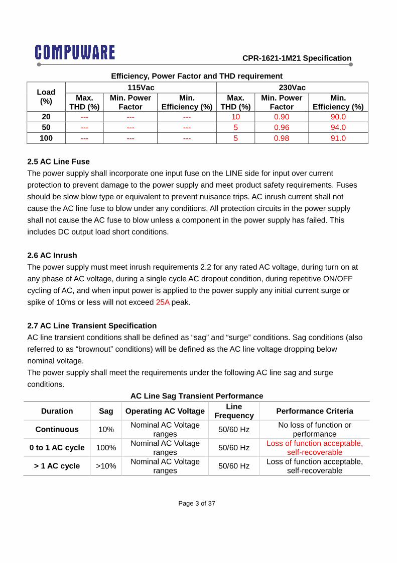
20 --- --- --- 10 0.90 90.0 50 --- --- --- 5 0.96 94.0
100 --- --- --- 5 0.98 91.0
2.5 AC Line Fuse
The power supply shall incorporate one input fuse on the LINE side for input over current
protection to prevent damage to the power supply and meet product safety requirements. Fuses
should be slow blow type or equivalent to prevent nuisance trips. AC inrush current shall not
cause the AC line fuse to blow under any conditions. All protection circuits in the power supply
shall not cause the AC fuse to blow unless a component in the power supply has failed. This
includes DC output load short conditions.
2.6 AC Inrush
The power supply must meet inrush requirements 2.2 for any rated AC voltage, during turn on at
any phase of AC voltage, during a single cycle AC dropout condition, during repetitive ON/OFF
cycling of AC, and when input power is applied to the power supply any initial current surge or
spike of 10ms or less will not exceed 25A peak.
2.7 AC Line Transient Specification
AC line transient conditions shall be defined as “sag” and “surge” conditions. Sag conditions (also
referred to as “brownout” conditions) will be defined as the AC line voltage dropping below
nominal voltage.
The power supply shall meet the requirements under the following AC line sag and surge
conditions.
AC Line Sag Transient Performance
Duration Sag Operating AC Voltage Line Frequency Performance Criteria
Continuous 10% Nominal AC Voltage ranges 50/60 Hz No loss of function or
performance
0 to 1 AC cycle 100% Nominal AC Voltage ranges
50/60 Hz Loss of function acceptable, self-recoverable
> 1 AC cycle >10% Nominal AC Voltage ranges
50/60 Hz Loss of function acceptable, self-recoverable

CPR-1621-1M21 Specification
Page 4 of 37
AC Line Surge Transient Performance
Duration Surge Operating AC Voltage Line Frequency Performance Criteria
Continuous 10% Nominal AC Voltages 50/60 Hz No loss of function or performance
0 to 1AC cycle 30% Mid-point of nominal AC Voltages 50/60 Hz No loss of function or
performance
2.8 AC Line Fast Transient Specification
The power supply shall meet the EN61000-4-5 directive and any additional requirements in
IEC1000-45:1995 and the Level 3 requirements for surge-withstand capability, with the following
conditions and exceptions:
• These input transients must not cause any out-of-regulation conditions, such as overshoot
and undershoot, nor must it cause any nuisance trips of any of the power supply protection
circuits.
• The surge-withstand test must not produce damage to the power supply.
• The supply must meet surge-withstand test conditions under maximum and minimum
output load conditions.
3 DC Output Specification 3.1 Output regulation Requirements
All outputs must maintain their regulation with the below limits when measured at the output
connector point or across the remote sense (if applicable) in any load condition defined in section
3.2
Voltage Regulation Limits
Output Minimum Nominal Maximum Unit +12V 11.40 12.0 12.60 Vdc
+5Vsb 4.75 5.0 5.25 Vdc
There should never be any negative voltage for all outputs and signals during all occasion,
including power on and off. During standby (PSON=off), all outputs, except +5VSB, should be
below 50mV.
3.2 Output Current Requirements
All outputs must maintain their regulation as section 3.1 when loaded to the following loading

CPR-1621-1M21 Specification
Page 5 of 37
combination:
Loading Limits Output Minimum Maximum Unit Input VAC
+12V 0.5 135 Adc 180 to 264 +12V 0.5 100 Adc 120 to 140 +12V 0.5 84 Adc 100 to 120
+5Vsb 0 4.0 (peak 6A) Adc 90 to 264
The total output power can not exceed 1005W continuously for 100 to 120VAC input, 1205W
continuously for 120 to 140VAC input and 1625W continuously for 180 to 264 VAC input. During
load changes from minimum to maximum or maximum to minimum the unit must not shut down.
Note: +5Vsb will be designed to meet 6A load requirement and will be tested with 6A load at
production line. However, model label ( I/O label) will print 5Vsb max rating with 4A only.
3.3 Output Ripple and Noise
The following output ripple/noise requirements will be met throughout the load ranges specified in
section 3.2 and under all input voltage conditions specified in section 2.1.
Ripple and noise are defined as periodic or random signals over the frequency band of 10Hz to
20MHz. Measurements will be made with an oscilloscope set to 20MHz bandwidth limit.
Measurement is done by using 10uF Tantalum in parallel with a 0.1uf ceramic capacitor, measured
directly at the output connector side (Note: care must be taken when doing measurements such
as using the smallest grounding wire.).
Ripple and Noise
Output Maximum Unit +12V 120 mV
+5Vsb 50 mV
3.4 Output Dynamic Loading
The output voltages shall remain within the limits specified in section 3.1 for the step loading and
within the limits specified in section 3.5 for the capacitive loading. The load transient repetition rate
shall be tested between 50 Hz and 5 kHz at duty cycles ranging from 10%-90%. The load
transient repetition rate is only a test specification. The ∆ step load may occur anywhere within the
MIN load to the MAX load shown in section 3.2

CPR-1621-1M21 Specification
Page 6 of 37
Transient Load Requirements Output ΔΔΔΔ Step Load Size Load Slew Rate Capacitive Load
+12V 65% of max load 0.5A/uS 2200uF +5Vsb 25% of max load 0.5A/uS 1uF 3.5 Capacitive Loading
The power supply shall be stable and meet all requirements, except dynamic loading requirements,
with the following capacitive loading ranges.
Capacitive Loading Conditions
Output MIN MAX Units +12 V 10 11,000 µF +5 VSB 1 350 µF
4 Redundancy Requirements 4.1 Current Sharing Operation
The power supply shall be designed for active current sharing for 12V main output.
Two or more power supplies will be paralleled in a system. Each power supply must be able to
share load to be within +/-20 % share error, measured at 25, 50, 100% of single power supply full
load current.
4.2 Output Isolation Oring MOSFET
The 12V output current must pass through an Oring MOSFET to protect the bus voltage against a
power supply internal fault.
4.3 Hot Swap
The power supply must be designed with “hot swap” function with or without active AC line cord.
After Hot swap I2C address shall be same as host power supply backplane hardware assigned.
Host existing working power supply shall not be affected by hot swapping power supply.
5 Controls and Signal 5.1 Timing Requirements
These are the timing requirements for the power supply operation.
The output voltages must rise from 10% to within regulation limits (Tvout_rise) within 5 to 70 ms.
Each output voltage shall reach regulation within 50 ms (Tvout_on) of each other during turn on of
CPR-1621-1M21 Specification
Page 7 of 37
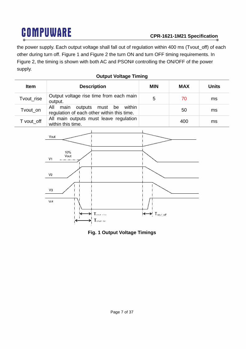
the power supply. Each output voltage shall fall out of regulation within 400 ms (Tvout_off) of each
other during turn off. Figure 1 and Figure 2 the turn ON and turn OFF timing requirements. In
Figure 2, the timing is shown with both AC and PSON# controlling the ON/OFF of the power
supply.
Output Voltage Timing
Item Description MIN MAX Units
Tvout_rise Output voltage rise time from each main output. 5 70 ms
Tvout_on All main outputs must be within regulation of each other within this time. 50 ms
T vout_off All main outputs must leave regulation within this time.
400 ms
Fig. 1 Output Voltage Timings

CPR-1621-1M21 Specification
Page 8 of 37
Figure 2 Turn On/Off Timing (Single Power Supply)
Item Description MIN MAX Units
Tsb_on_delay Delay from AC being applied to 5 VSB being within regulation.
1500 ms
T ac_on_delay Delay from AC being applied to all output voltages being within regulation.
2500 ms
Tvout_holdup Time all output voltages stay within regulation after loss of AC. Tested at 75% of maximum load and over 100-240VAC input
17 ms
Tdc_good_holdup Delay from loss of AC to deassertion of DC Good
16 ms
Tpson_on_delay
Delay from PSON# active to output voltages within regulation limits.
5 400 ms
Tsb_vout Delay from 5 VSB being in regulation to O/Ps being in 50 500 ms

CPR-1621-1M21 Specification
Page 9 of 37
regulation at AC turn on.
Tpson_dc_good Delay from PSON# deactive to DC Good being deasserted. 50 ms
Tdc_good _on Delay from output voltages within regulation limits to DC Good asserted at turn on.
100 120 ms
Tdc_good _off Delay from DC Good deasserted to output voltages dropping out of regulation limits.
1 ms
Tsb_vout Delay from 5 VSB being in regulation to O/Ps being in regulation at AC turn on.
50 1000 ms
Tsb_holdup Time 5VSB output voltage stays within regulation after loss of AC. 70 ms
Tsb_Vout_rise The rising time for +5VSB start up to be in regulation 1 25 ms
5.2 PS_ON
The PSONsignal is required to remotely turn on/off the power supply. PSON is an active low signal
that turns on the +12 V power rail. When this signal is not pulled low by the system, or left open,
the outputs (except the +5 Vsb) turn off. This signal is pulled to a standby voltage by a pull-up
resistor internal to the power supply.
PSON Signal Characteristic Signal Type Accepts an open collector/drain input from the
system. Pull-up to VSB located in power supply. PSON# = Low ON PSON# = Open or High OFF MIN MAX Logic level low (power supply ON) 0 V 1.0 V Logic level high (power supply OFF) 2.0 V 5.25 V Source current, Vpson = low 4 mA Power up delay: Tpson_on_delay 5 ms 400 ms PWOK delay: Tpson_pwok 50 ms
CPR-1621-1M21 Specification
Page 10 of 37
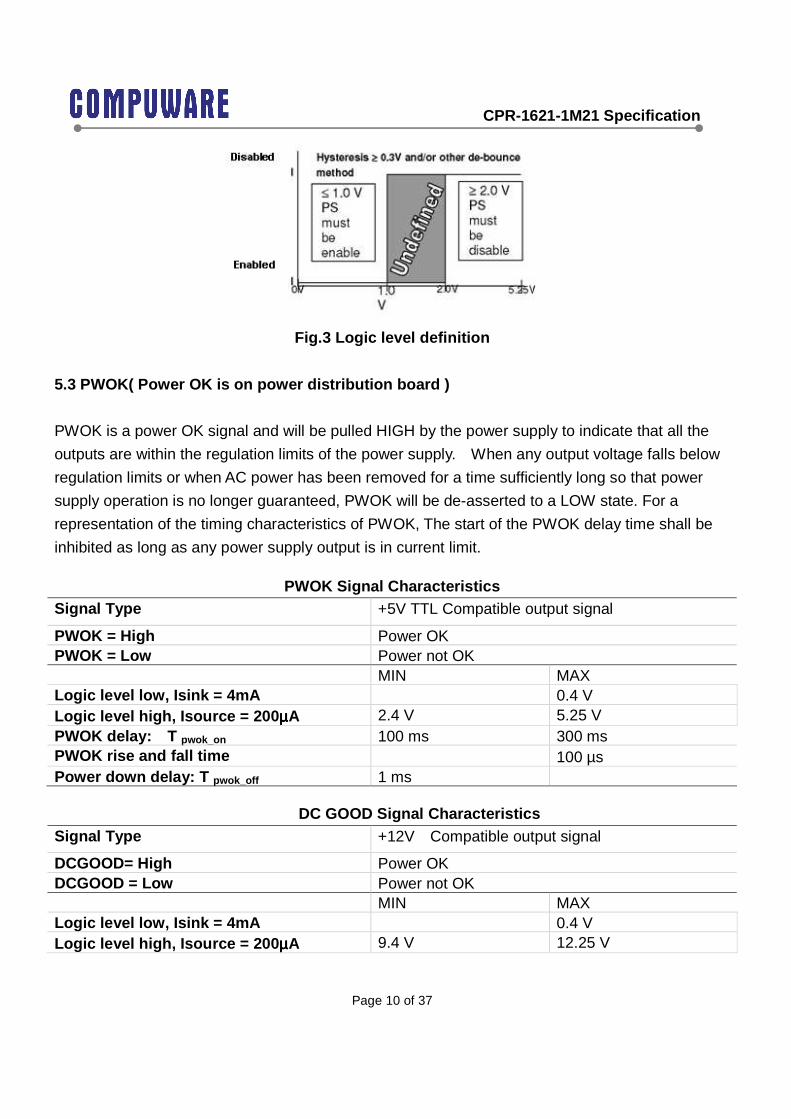
Fig.3 Logic level definition
5.3 PWOK( Power OK is on power distribution board )
PWOK is a power OK signal and will be pulled HIGH by the power supply to indicate that all the
outputs are within the regulation limits of the power supply. When any output voltage falls below
regulation limits or when AC power has been removed for a time sufficiently long so that power
supply operation is no longer guaranteed, PWOK will be de-asserted to a LOW state. For a
representation of the timing characteristics of PWOK, The start of the PWOK delay time shall be
inhibited as long as any power supply output is in current limit.
PWOK Signal Characteristics Signal Type +5V TTL Compatible output signal
PWOK = High Power OK PWOK = Low Power not OK MIN MAX Logic level low, Isink = 4mA 0.4 V Logic level high, Isource = 200 µµµµA 2.4 V 5.25 V PWOK delay: T pwok_on 100 ms 300 ms PWOK rise and fall time 100 µs Power down delay: T pwok_off 1 ms
DC GOOD Signal Characteristics Signal Type +12V Compatible output signal
DCGOOD= High Power OK DCGOOD = Low Power not OK MIN MAX Logic level low, Isink = 4mA 0.4 V Logic level high, Isource = 200 µµµµA 9.4 V 12.25 V
CPR-1621-1M21 Specification
Page 11 of 37
DCGOOD delay: T dcgood_on 100 ms 120 ms DCGOOD rise and fall time 100 µs
5.4 AC Warning
Noted on PMBus 1.2 standard.
5.5 LED Indicator
A green/amber double color Light Emitting Diode (LED) shall be mounted as indicated in
mechanical drawing and shall indicate the status of the DC GOOD signal with green color. The
LED shall continue to glow under normal operation of the power supply. If this LED is blinking or
not lit or in amber color, the power supply is not operating properly.
During protection mode, the LED should be off.
When protection is cleared, the LED should go back to the original intended status.
When the unit is in standby with AC is present, the LED should be amber.
When the unit is in standby with no AC is present, the LED should be off.
When the unit is turned on properly, the LED is green.
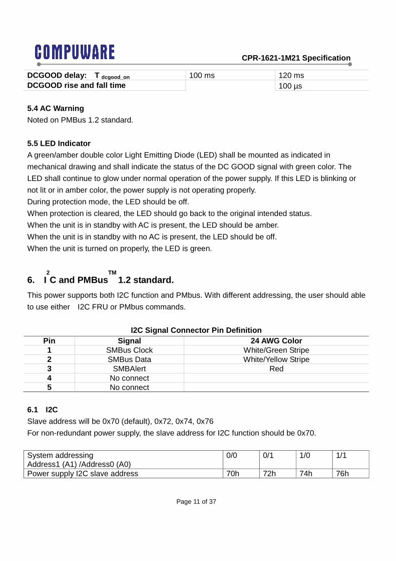
6. I2C and PMBus
TM 1.2 standard.
This power supports both I2C function and PMbus. With different addressing, the user should able
to use either I2C FRU or PMbus commands.
I2C Signal Connector Pin Definition Pin Signal 24 AWG Color 1 SMBus Clock White/Green Stripe 2 SMBus Data White/Yellow Stripe 3 SMBAlert Red 4 No connect 5 No connect
6.1 I2C
Slave address will be 0x70 (default), 0x72, 0x74, 0x76
For non-redundant power supply, the slave address for I2C function should be 0x70.
System addressing Address1 (A1) /Address0 (A0)
0/0 0/1 1/0 1/1
Power supply I2C slave address 70h 72h 74h 76h

CPR-1621-1M21 Specification
Page 12 of 37
The power supply can be read and written to as if it’s a 2k bit (256 byte) I2C EEPROM. The power
supply must support: Byte write and Random read. Read and write must work at speeds up to 100
kHz. This bus shall operate at nominal voltage 3.3V but be tolerant of 5V signaling.
All the data stored in the power supply follows FRU spec, IPMI, Platform Management FRU
information Storage Definition v1.0.
FRU spec attached below:
The “Chassis Info” and “Board Info” are not to be implemented. The “Common Header” and
“Product Area” are required.
For the “Multiple Record” area, the power supply should implement the “Power Supply
Information”, and multiple “DC Output” section as needed.
For the “Product Info” area must began from offset location 0x18 (offset 0x04 product information
offset must contains value of 0x03).
The “Internal Use” section as follows: Offset Result of a read 0x09 Temperature
(hot spot) Value to represent the current temperature of the hottest spot inside the power supply This is an unsigned integer value in Celsius.
0x0A Fan 1 speed (main fan)
Value to represent the RPM of the power supply fan #1 This should be the fan pulse count in 262 ms. We are assuming that two fan pulses equal one rotation. The system software will convert this value, to fan RPM, using: RPM=(1/0.262) *(Fan Pulse Count * 60 /2)
0x0B Fan 2 speed (secondary fan if available)
Value to represent the RPM of the power supply fan #1 This should be the fan pulse count in 262 ms. We are assuming that two fan pulses equal one rotation. The system software will convert this value, to fan RPM, using: RPM=(1/0.262) *(Fan Pulse Count * 60 /2) If fan 2 is not available, default value 0x00

CPR-1621-1M21 Specification
Page 13 of 37
0x0C Power Status Value to represent DC GOOD status byte = hex 01 means DC GOOD byte = 00 means no DC output
0x0D Temperature High Limit (hot spot)
Value is fixed and should be the highest acceptable temperature that the power supply can sustain based on offset 09. This value is for information display purpose only and is independent from protection or fan control design. Modifying this byte will not affect the power supply operation.
0x0E Fan 1 speed Low Limit
Value is fixed and should be the lowest fan #1 RPM acceptable This value is for information display purpose only and is independent from protection or fan control design. Modifying this byte will not affect the power supply operation.
0x0F Fan 2 speed Low Limit (if secondary fan is available)
Value is fixed and should be the lowest fan #2 RPM acceptable If fan 2 is not available, default value 0x00 This value is for information display purpose only and is independent from protection or fan control design. Modifying this byte will not affect the power supply operation.
0x14 AC RMS current This byte, divided by 16, is the AC (RMS) input current. 0x15 DC output current
(optional) This byte is the DC output current. If this function is not available, default value is 0x00
0x16 Firmware version Example: version 2.0 is encoded as 0x20 Anything less than 2.0 (0x20) found at this location will be reported as version 1.0 Default initial value 0x10
0x17 FRU file revision Integer only 0xF0 AC current limit AC current upper limit; This byte, divided by 16, is the AC input
current limit This value is for information display purpose only and is independent from protection or control logic design. Modifying this byte will not affect the power supply operation.
0xF1 +12V DC current limit
+12V DC current upper limit; this byte is the DC (+12V) output current. This value is for information display purpose only and is independent from protection or control logic design. Modifying this byte will not affect the power supply operation.
0xF2 Power supply output wattage rating
Power supply output wattage rating; lower byte. If the output wattage changes according to different AC input voltage range, this output should reflect accordingly.
0xF3 Power supply output wattage rating
Power supply output wattage rating; higher byte. If the output wattage changes according to different AC input voltage range, this output should reflect accordingly.
0xF4 Input voltage 100-240Vac input voltage reading (for readings above 255Vac, it
CPR-1621-1M21 Specification
Page 14 of 37
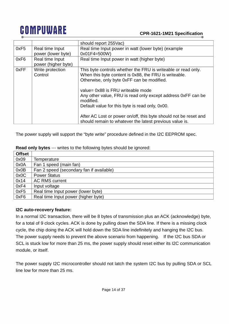
should report 255Vac) 0xF5 Real time Input
power (lower byte) Real time Input power in watt (lower byte) (example 0x01F4=500W)
0xF6 Real time Input power (higher byte)
Real time Input power in watt (higher byte)
0xFF Write protection Control
This byte controls whether the FRU is writeable or read only. When this byte content is 0x88, the FRU is writeable. Otherwise, only byte 0xFF can be modified. value= 0x88 is FRU writeable mode Any other value, FRU is read only except address 0xFF can be modified. Default value for this byte is read only, 0x00. After AC Lost or power on/off, this byte should not be reset and should remain to whatever the latest previous value is.
The power supply will support the “byte write” procedure defined in the I2C EEPROM spec.
Read only bytes --- writes to the following bytes should be ignored: Offset 0x09 Temperature 0x0A Fan 1 speed (main fan) 0x0B Fan 2 speed (secondary fan if available) 0x0C Power Status 0x14 AC RMS current 0xF4 Input voltage 0xF5 Real time Input power (lower byte) 0xF6 Real time Input power (higher byte)
I2C auto-recovery feature:
In a normal I2C transaction, there will be 8 bytes of transmission plus an ACK (acknowledge) byte,
for a total of 9 clock cycles. ACK is done by pulling down the SDA line. If there is a missing clock
cycle, the chip doing the ACK will hold down the SDA line indefinitely and hanging the I2C bus.
The power supply needs to prevent the above scenario from happening. If the I2C bus SDA or
SCL is stuck low for more than 25 ms, the power supply should reset either its I2C communication
module, or itself.
The power supply I2C microcontroller should not latch the system I2C bus by pulling SDA or SCL
line low for more than 25 ms.

CPR-1621-1M21 Specification
Page 15 of 37
The power supply needs to have 4.7k Ohm internal pull up on the SDA or SCL lines and operate
with 3.3V nominal voltage level.
6.2 PMBus
The PMbus specification is based on the PMBus specification parts I and II, revision 1.1 and 1.2.
PMBus Power System Management Protocol Specification Part I – General Requirements,
Transport and Electrical Interface; Revision 1.2; Reference: http://pmbus.org/specs.html
PMBus Power System Management Protocol Specification Part II – Command Language;
Revision 1.2; Reference: http://pmbus.org/specs.html
System Management Bus (SMBus) Specification version 2.0; Reference: http://smbus.org/specs/
6.2.1 Addressing
The power supply PMbus device address locations are shown below. For redundant systems
there are up to 2 signals to set the address location of the power supply once it is install in the
system: A1, A0. For no-redundant systems the power supply device address location should be
78h.
System addressing Address1 (A1) /Address0 (A0)
0/0 0/1 1/0 1/1
Power supply PMBusTM device 78h 7Ah 7Ch 7Eh Note: Non-redundant power supplies will use the 0/0 address location, 78h.
6.2.2 Command
The following PMBus commands shall be supported for the purpose of monitoring currents,
voltages, and power. All data should use the linear data format as documented in PMbus spec.
PMBus command Command Offset location
Byte size Description
CLEAR_FAULTS 0x03 1 Writing any value into this byte will reset all the fault status
PAGE_PLUS_WRITE 0x05 variable used with STATUS_INPUT, STATUS_TEMPERATURE, STATUS_IOUT
CPR-1621-1M21 Specification
Page 16 of 37
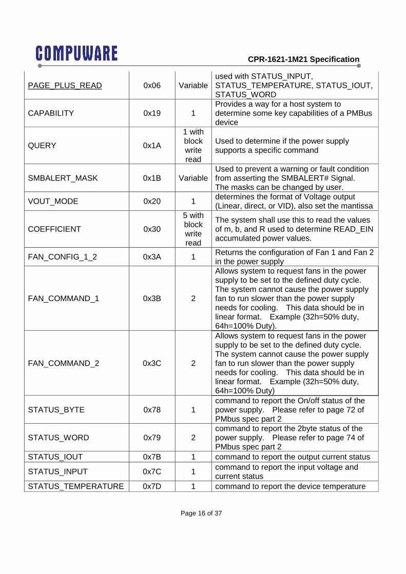
PAGE_PLUS_READ 0x06 Variable used with STATUS_INPUT, STATUS_TEMPERATURE, STATUS_IOUT, STATUS_WORD
CAPABILITY 0x19 1 Provides a way for a host system to determine some key capabilities of a PMBus device
QUERY 0x1A
1 with block write read
Used to determine if the power supply supports a specific command
SMBALERT_MASK 0x1B Variable Used to prevent a warning or fault condition from asserting the SMBALERT# Signal. The masks can be changed by user.
VOUT_MODE 0x20 1 determines the format of Voltage output (Linear, direct, or VID), also set the mantissa
COEFFICIENT 0x30
5 with block write read
The system shall use this to read the values of m, b, and R used to determine READ_EIN accumulated power values.
FAN_CONFIG_1_2 0x3A 1 Returns the configuration of Fan 1 and Fan 2 in the power supply
FAN_COMMAND_1 0x3B 2
Allows system to request fans in the power supply to be set to the defined duty cycle. The system cannot cause the power supply fan to run slower than the power supply needs for cooling. This data should be in linear format. Example (32h=50% duty, 64h=100% Duty).
FAN_COMMAND_2 0x3C 2
Allows system to request fans in the power supply to be set to the defined duty cycle. The system cannot cause the power supply fan to run slower than the power supply needs for cooling. This data should be in linear format. Example (32h=50% duty, 64h=100% Duty)
STATUS_BYTE 0x78 1 command to report the On/off status of the power supply. Please refer to page 72 of PMbus spec part 2
STATUS_WORD 0x79 2 command to report the 2byte status of the power supply. Please refer to page 74 of PMbus spec part 2
STATUS_IOUT 0x7B 1 command to report the output current status
STATUS_INPUT 0x7C 1 command to report the input voltage and current status
STATUS_TEMPERATURE 0x7D 1 command to report the device temperature

CPR-1621-1M21 Specification
Page 17 of 37
status STATUS_FANS_1_2 0x81 1 command to report the fan status
READ_EIN 0x86 6 with block read
Command to report the accumulated input power (Total power usage since AC on)
READ_VIN 0x88 2 RMS input voltage in volts(note; not used on power distribution boards) Should reset to 0 when AC is lost
READ_IIN 0x89 2 RMS input current in amps (note; not used on power distribution boards) Should report 0 when AC is lost or in standby
READ VOUT 0x8B 2 12V Output Voltage (should reset to 0 during standby or AC is removed)
READ IOUT 0x8C 2 12V Output Current (should reset to 0 during standby or AC is removed)
READ_TEMPERATURE1 (Ambient) 0x8D 2 Read airflow inlet temperature (should be
similar to the ambient temperature)
READ_TEMPERATURE2 (hot Spot) 0x8E 2
Read hotspot temperature (should be the hottest location inside the unit)
READ_FAN_SPEED_1 0x90 2 Returns the fan speed in RPM of fan sensor 1. This data should be in linear format
READ_FAN_SPEED_2 0x91 2 Returns the fan speed in RPM of fan sensor 2. This data should be in linear format
READ POUT 0X96 2 12V DC Output in Watts
READ PIN 0x97 2
AC input power in watts (note; not used on power distribution boards). Value should reset to 0W when in standby mode or AC is lost.
PMBUS_REVISION 0x98 1 Reads the revision of the PMBus to which the device is compliant (default value 22h)
APP_PROFILE_SUPPORT 0x9F
2 with
block read
Defines that the power supply supports this application profile (default profile 04h), profile revision 1.0, (default revision value 10h)
MFR_VIN_MIN 0xA0 2 Retrieves the minimum rated value, in volts, of input voltage (ex. 90Vac). This value remains a constant value.
MFR_VIN_MAX 0xA1 2 Retrieves the maximum rated value, in volts, of input voltage (ex. 264Vac). This value is a constant value.
CPR-1621-1M21 Specification
Page 18 of 37
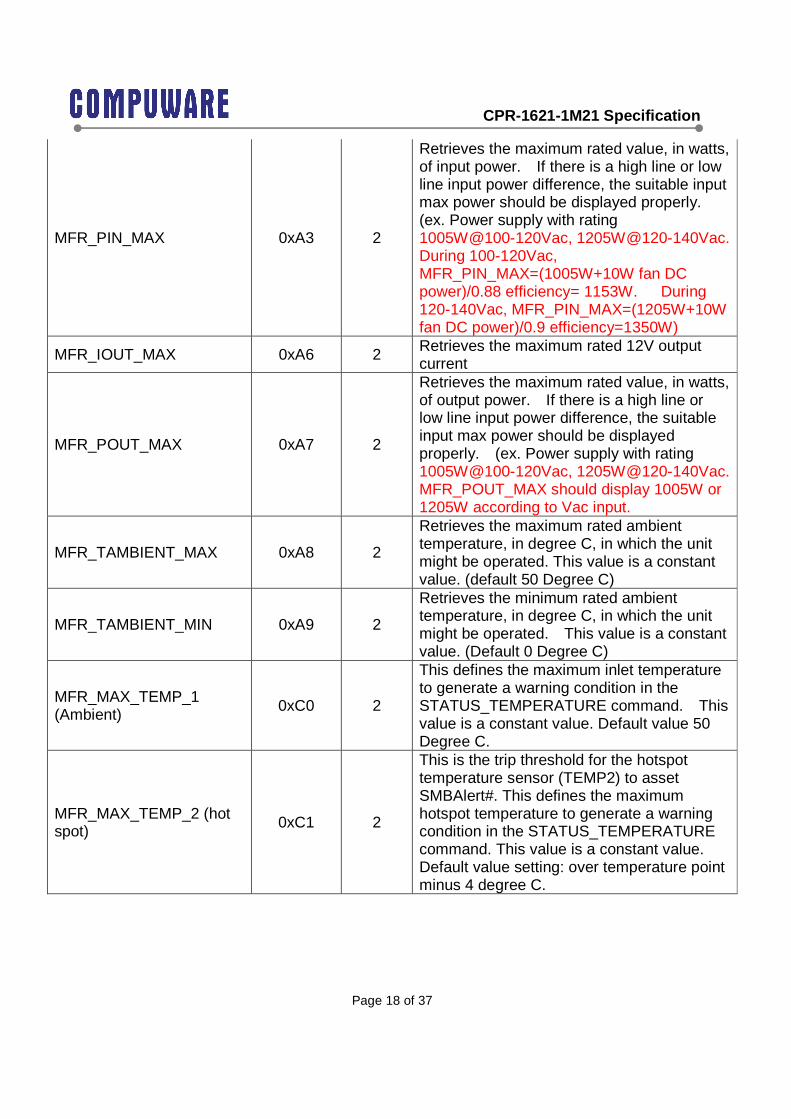
MFR_PIN_MAX 0xA3 2
Retrieves the maximum rated value, in watts, of input power. If there is a high line or low line input power difference, the suitable input max power should be displayed properly. (ex. Power supply with rating 1005W@100-120Vac, 1205W@120-140Vac. During 100-120Vac, MFR_PIN_MAX=(1005W+10W fan DC power)/0.88 efficiency= 1153W. During 120-140Vac, MFR_PIN_MAX=(1205W+10W fan DC power)/0.9 efficiency=1350W)
MFR_IOUT_MAX 0xA6 2 Retrieves the maximum rated 12V output current
MFR_POUT_MAX 0xA7 2
Retrieves the maximum rated value, in watts, of output power. If there is a high line or low line input power difference, the suitable input max power should be displayed properly. (ex. Power supply with rating 1005W@100-120Vac, 1205W@120-140Vac. MFR_POUT_MAX should display 1005W or 1205W according to Vac input.
MFR_TAMBIENT_MAX 0xA8 2
Retrieves the maximum rated ambient temperature, in degree C, in which the unit might be operated. This value is a constant value. (default 50 Degree C)
MFR_TAMBIENT_MIN 0xA9 2
Retrieves the minimum rated ambient temperature, in degree C, in which the unit might be operated. This value is a constant value. (Default 0 Degree C)
MFR_MAX_TEMP_1 (Ambient) 0xC0 2
This defines the maximum inlet temperature to generate a warning condition in the STATUS_TEMPERATURE command. This value is a constant value. Default value 50 Degree C.
MFR_MAX_TEMP_2 (hot spot) 0xC1 2
This is the trip threshold for the hotspot temperature sensor (TEMP2) to asset SMBAlert#. This defines the maximum hotspot temperature to generate a warning condition in the STATUS_TEMPERATURE command. This value is a constant value. Default value setting: over temperature point minus 4 degree C.

CPR-1621-1M21 Specification
Page 19 of 37
VOUT_MODE Command Definition:
For reading output voltages the power supply shall support the VOUT_MODE command to report
the output voltage formatting for the READ_VOUT command. The VOUT_MODE shall be set to
Linear and the exponent (N) shall be set to -9.
VOUT_MODE settings for reading output voltage(s). Mode Bits [7:5] Bits [4:0] (N) Linear 000b 10111b (-9)
FAN_COMMAND_1_2 Command Definition:
The system may increase the power supplies fan speed through using the FAN_COMMAND
Command. This command can only increase the power supply fan speed; it cannot decrease the
power supply fan speed below what the power supply commands.
The control is configured to be duty cycle controlled using the linear format of the PMBus protocol.
The exponent N is fixed to a value of 0 (N=0). The command ranges from value 0000h (0% duty)
to 0064h (100% duty).
STATUS Commands:
The following PMBus STATUS commands shall be supported. All STATUS commands except
the STATUS_FAN_1_2 and STATUS_BYTE commands shall be accessed with the PAGE_PLUS
command since they are used by both the BMC and ME. The (BMC) and (ME) refer to the two
instances of the command accessed via the PAGE_PLUS command. The status bits shall assert
whenever the event driving the status bit is present. Once a bit is asserted it shall stay asserted
until cleared using one of the five methods described below:
1) Writing a ‘1’ to any given bit location shall reset on that bit of the command
2) Sending a CLEAR_FAULTS command to the power supply shall reset all STATUS_ bits to
‘0’
3) Cycling AC power OFF(when Vin below 90Vac) than ON (when Vin above 90Vac) shall
reset all STATUS_ bits to ‘0’.

CPR-1621-1M21 Specification
Page 20 of 37
4) Systems with redundant power supplies where only one of the supplies cycle AC power
OFF/ON; the power cycled power supply shall reset the STATUS_ bits to ‘0’ only when
powered back ON. If the power supply is kept OFF, the STATUS_ bits shall not be reset.
5) Cycling the PSON# signal from de-asserted to asserted shall reset the STATUS_ bits to ‘0’.
The bits shall be reset only on the assertion of PSON#; not the de-assertion.
STATUS_BYTE: Please refer to PMbus part 2 Spec.
Offset 0x78 PAGES
00h=BMC 01h=ME
SMBAlert_MASK Default (0=causes assertion of SMBAlert#, 1=does not cause assertion of SMBAlert#) STATUS_Byte SMBAlert Mask is not user changeable
7 Not used, default=0 00h, 01h 1
6 Device is off due to PSON or for any reason (ex. Protection)=1, else 0 00h, 01h 1
5 Output OVP fault=1, else 0 00h, 01h 1 4 Output OCP fault =1, else 0 00h, 01h 1 3 Vin under voltage fault =1, else 0 00h, 01h 1 2 OTP fault =1; else 0 00h, 01h 1 1 CML communication error=1, else 0 00h, 01h 1
Bit #
0 Other fault (A fault or warning not listed in bit [7:1] of this byte has occurred)=1, else=0 00h, 01h 1
STATUS_WORD: Please refer to PMbus part 2 Spec.
Byte STATUS_WORD, Offset 0x79 PAGES
00h=BMC 01h=ME
SMBAlert_MASK Default (0=causes assertion of SMBAlert#, 1=does not cause assertion of SMBAlert#) STATUS_Word SMBAlert Mask is not user changeable
7 Not used, default=0 00h, 01h 1 Low
6 Device is off due to PSON or for any reason (ex. Protection)=1, else 0
00h, 01h 1

CPR-1621-1M21 Specification
Page 21 of 37
5 Output OVP fault occur=1, else 0
00h, 01h 1
4 Output OCP fault occur =1, else 0 00h, 01h 1
3 Vin under voltage fault occur =1, else 0 00h, 01h 1
2 OTP fault occur=1; else 0 00h, 01h 1
1 CML communication error=1, else 0
00h, 01h 1
0 Other Fault (A fault or warning not listed in bit [7:1] of this byte has occurred)=1, else=0
00h, 01h 1
7 VOUT Fault or warning=1, else 0 00h, 01h 1
6 IOUT/POUT fault or warning=1, else 0
00h, 01h 1
5 An input voltage, input current, or input power fault or warning=1, else 0
00h, 01h 1
4 Not used, default=0 00h, 01h 1
3 Power Good signal is not good (logic low)=1, else 0 00h, 01h 1
2 Fan fault or warning=1, else 0 00h, 01h 1 1 Not used, default=0 00h, 01h 1
High
0 Not used, default=0 00h, 01h 1
STATUS_IOUT Command Definition:
PAGES 00h=BMC
Bit STATUS_IOUT, Offset 0x7B 01h=ME
SMBAlert_MASK Default (0=causes assertion of SMBAlert#, 1=does not cause assertion of SMBAlert#)
7 IOUT Overcurrent Fault 00h, 01h 1
6 Not used, default=0 00h, 01h 1
5 IOUT Overcurrent Warning (greater than rated output current for more than 1second)
00h, 01h 1
4 Not used, default=0 00h, 01h 1
3 Not used, default=0 00h, 01h 1
2 Not used, default=0 00h, 01h 1
1 POUT Overpower Fault 00h, 01h 1
CPR-1621-1M21 Specification
Page 22 of 37
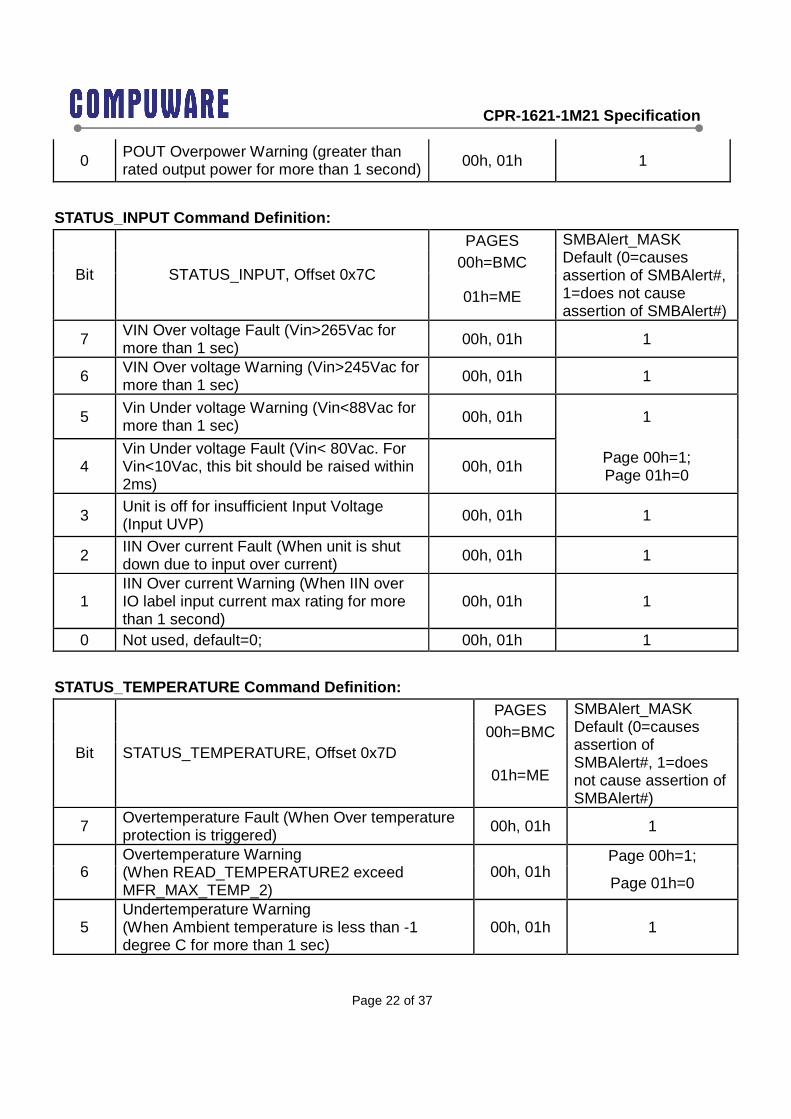
0 POUT Overpower Warning (greater than rated output power for more than 1 second) 00h, 01h 1
STATUS_INPUT Command Definition: PAGES
00h=BMC Bit STATUS_INPUT, Offset 0x7C
01h=ME
SMBAlert_MASK Default (0=causes assertion of SMBAlert#, 1=does not cause assertion of SMBAlert#)
7 VIN Over voltage Fault (Vin>265Vac for more than 1 sec) 00h, 01h 1
6 VIN Over voltage Warning (Vin>245Vac for more than 1 sec) 00h, 01h 1
5 Vin Under voltage Warning (Vin<88Vac for more than 1 sec) 00h, 01h 1
4 Vin Under voltage Fault (Vin< 80Vac. For Vin<10Vac, this bit should be raised within 2ms)
00h, 01h Page 00h=1; Page 01h=0
3 Unit is off for insufficient Input Voltage (Input UVP) 00h, 01h 1
2 IIN Over current Fault (When unit is shut down due to input over current) 00h, 01h 1
1 IIN Over current Warning (When IIN over IO label input current max rating for more than 1 second)
00h, 01h 1
0 Not used, default=0; 00h, 01h 1
STATUS_TEMPERATURE Command Definition: PAGES
00h=BMC Bit STATUS_TEMPERATURE, Offset 0x7D
01h=ME
SMBAlert_MASK Default (0=causes assertion of SMBAlert#, 1=does not cause assertion of SMBAlert#)
7 Overtemperature Fault (When Over temperature protection is triggered)
00h, 01h 1
Page 00h=1; 6
Overtemperature Warning (When READ_TEMPERATURE2 exceed MFR_MAX_TEMP_2)
00h, 01h Page 01h=0
5 Undertemperature Warning (When Ambient temperature is less than -1 degree C for more than 1 sec)
00h, 01h 1

CPR-1621-1M21 Specification
Page 23 of 37
4 Undertemperature Fault (When unit is unable to turn on due to low ambient temperature)
00h, 01h 1
3 Not used, default=0; 00h, 01h 1
2 Not used, default=0; 00h, 01h 1
1 Not used, default=0; 00h, 01h 1
0 Not used, default=0; 00h, 01h 1
STATUS_FANS_1_2 Command Definition: PAGES
00h=BMC
Bit STATUS_FANS_1_2, Offset 0x81 01h=ME
SMBAlert_MASK Default (0=causes assertion of SMBAlert#, 1=deso not cause assertion of SMBAlert#)
7 Fan 1 Fault=1, else=0 N/A 1
6 Fan 2 Fault=1, else=0 N/A 1
5 Not used, default=0; N/A 1
4 Not used, default=0; N/A 1
3 Fan 1 Speed Overridden (When User command is applied)=1; else 0 N/A 1
2 Fan 2 Speed Overridden (When User command is applied)=1; else 0 N/A 1
1 Not used, default=0; N/A 1
0 Not used, default=0; N/A 1
PMBUS_REVISION Command Value: Bits 7:4 Part I Revision Bits 3:0 Part II Revision
0010 1.2 0010 1.2
APP_PROFILE_SUPPORT Command:
The Block Read/Write protocol is used with this command.
First Byte for supporting Romley Profile: 04h
Second Byte for supporting Romley Profile rev 1.0: 10h
6.2.3 Manufacturer Specific Commands:
Offset 0xD0-0xDE is used to represent the unit model serial number. Data represented in byte
format.
CPR-1621-1M21 Specification
Page 24 of 37
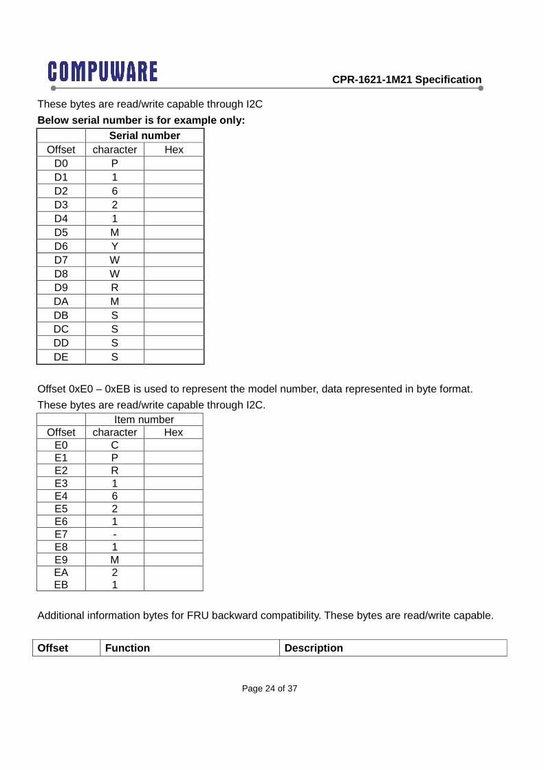
These bytes are read/write capable through I2C
Below serial number is for example only: Serial number
Offset character Hex D0 P D1 1 D2 6 D3 2 D4 1 D5 M D6 Y D7 W D8 W D9 R DA M DB S DC S DD S DE S
Offset 0xE0 – 0xEB is used to represent the model number, data represented in byte format.
These bytes are read/write capable through I2C. Item number
Offset character Hex E0 C E1 P E2 R E3 1 E4 6 E5 2 E6 1 E7 - E8 1 E9 M EA 2 EB 1
Additional information bytes for FRU backward compatibility. These bytes are read/write capable.
Offset Function Description

CPR-1621-1M21 Specification
Page 25 of 37
ED Temperature upper limit Internal temperature upper limit in degree Celsius. Direct data format, data length is one byte.
EE Fan 1 pulse count lower limit
Value to represent the lower limit RPM of the power supply fan #1 The system software will convert this value, to fan RPM, using: RPM limit=(1/0.262) *(Fan Pulse Count limit * 60 /2)
EF Fan 2 pulse count lower limit
Value to represent the lower limit RPM of the power supply fan #2 The system software will convert this value, to fan RPM, using: RPM limit=(1/0.262) *(Fan Pulse Count limit * 60 /2)
Offset 0xF0-0xF5 is used to represent the unit revision number. Revision begins with Rev 1.0.
Data is represented in byte format. These bytes are read/write capable using I2C. Revision Offset character Hex F0 R F1 E F2 V F3 1 F4 . F5 0
6.2.4 Sensor Sampling
The sensor registers inside the power supply for monitoring input/output power, current, and
voltage shall meet the following minimum requirements. Register refresh rate is the frequency
the sensor register gets updated with a new measurement value.
Register refresh rate ≥ 10Hz
6.2.5 Sensor Averaging
The sensor registers for monitoring input/output power, current, and voltage shall contained
averaged data, not instantaneous peak data. This may be achieved in two ways; an arithmetic
average or a low pass filter. An exponential moving average shall not be used. The power supply

CPR-1621-1M21 Specification
Page 26 of 37
shall refresh the sensor data at a rate no slower than the averaging duration.
READ_PIN, shall be an average value over a 2 second interval.
READ_IIN and READ_VIN shall be an RMS value over a 2 second interval.
6.2.6 Accuracy
The sensor commands shall meet the following accuracy requirements.
10% of max load 20% of
max load
50% of max load
100% of max load
READ_IIN +/-5% +/-5% +/-5% +/-2% READ_PIN +/-5% or +/- 10W
(which ever tolerance is larger)
+/-5% +/-5% +/-5%
READ_IOUT +/-5% +/-3% +/-5% +/-3% READ_POUT +/-5% or +/- 10W
(which ever tolerance is larger)
+/-5% +/-5% +/-5%
READ_VIN +/- 2% over full range READ_VOUT +/- 2% over full range READ_TEMPERATURE Required: +/-3 ºC
6.3 SMBAlert
The SMBAlert# Signal may be asserted (pulled low, less than 0.4V) by the power supply for any of
the supported STATUS events. The events that control SMBAlert# can be masked during the
SMBALERT_MASK command. Default masking is shown the status command definitions.
By default the SMBAlert# signal is asserted for the following cases:
1) AC Input voltage drops below the fault threshold (<10Vac) for more than 2ms.
2) Thermal sensor on a hot spot inside the power supply has exceeded its warning
temperature (MFR_MAX_TEMP2)
3) Power supply is turned off due to PSON
The power supply does not support Alert Response Address (ARA). After asserting the
SMBAlert# signal, the power supply shall keep its address at its standard address; not change to
CPR-1621-1M21 Specification
Page 27 of 37
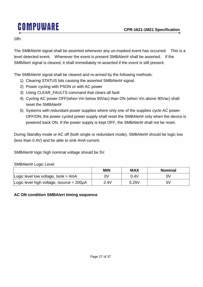
18h.
The SMBAlert# signal shall be asserted whenever any un-masked event has occurred. This is a
level detected event. Whenever the event is present SMBAlert# shall be asserted. If the
SMBAlert signal is cleared, it shall immediately re-asserted if the event is still present.
The SMBAlert# signal shall be cleared and re-armed by the following methods:
1) Clearing STATUS bits causing the asserted SMBAlert# signal.
2) Power cycling with PSON or with AC power
3) Using CLEAR_FAULTS command that clears all fault
4) Cycling AC power OFF(when Vin below 90Vac) than ON (when Vin above 90Vac) shall
reset the SMBAlert#
5) Systems with redundant power supplies where only one of the supplies cycle AC power
OFF/ON; the power cycled power supply shall reset the SMBAlert# only when the device is
powered back ON. If the power supply is kept OFF, the SMBAlert# shall not be reset.
During Standby mode or AC off (both single or redundant mode), SMBAlert# should be logic low
(less than 0.4V) and be able to sink 4mA current.
SMBAlert# logic high nominal voltage should be 5V.
SMBAlert# Logic Level
MIN MAX Nominal
Logic level low voltage, Isink = 4mA 0V 0.4V 0V
Logic level high voltage, Isource = 200µA 2.4V 5.25V 5V
AC ON condition SMBAlert timing sequence

CPR-1621-1M21 Specification
Page 28 of 37
PSON=off power down condition (AC always ON) SMBAlert timing sequence
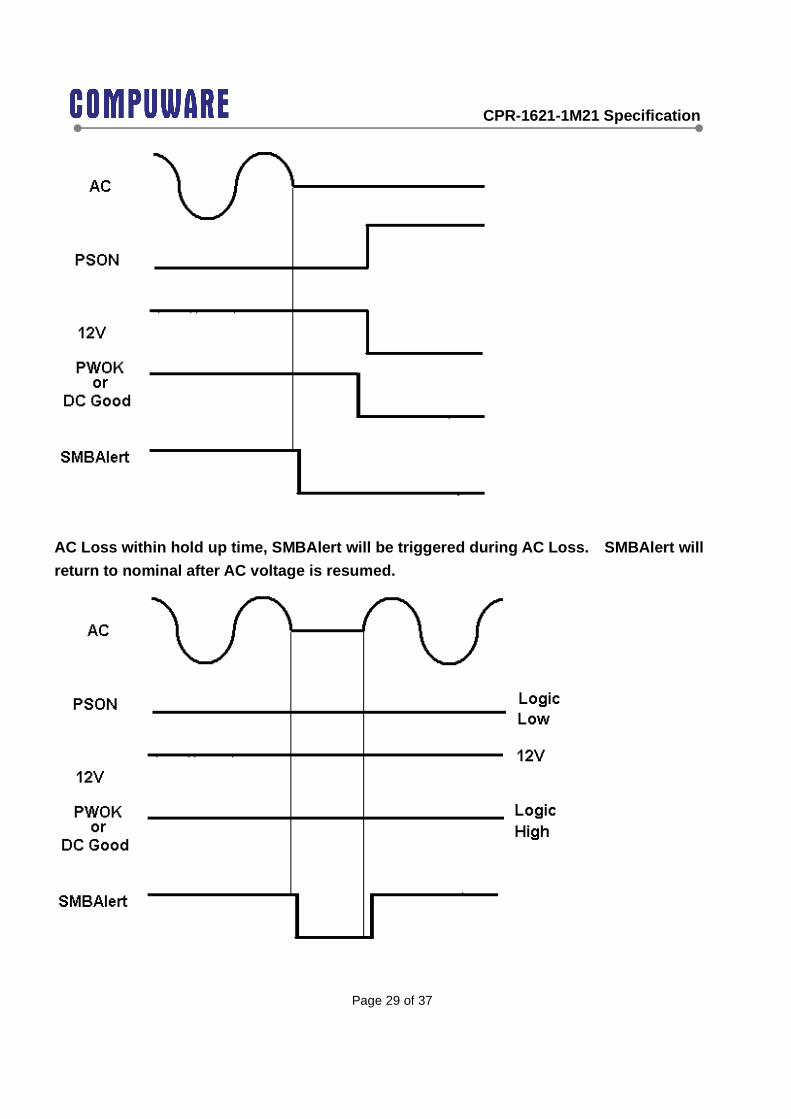
Power down condition due to AC OFF SMBAlert timing sequence
CPR-1621-1M21 Specification
Page 29 of 37
AC Loss within hold up time, SMBAlert will be triggered during AC Loss. SMBAlert will
return to nominal after AC voltage is resumed.

CPR-1621-1M21 Specification
Page 30 of 37
6.4 Faults and Error Checking
The power supply shall support PEC(packet error checking) per the SMBus 2.0 specification.
The power supply shall also support and respond to commands which do not contain PEC(packet
error checking).
7 Protection Circuits Protection circuits inside the power supply shall cause only the power supply’s main outputs to
shutdown If the power supply latches off due to a protection circuit tripping, an AC cycle OFF for
15 seconds and a PSON cycle HIGH for 1 second shall be able to reset the power supply.
7.1 Over Current Protection
The power supply shall have current limit to prevent +12 V outputs from exceeding the values
shown in below table. If the +12V current limits are exceeded the power supply shall shutdown
and latch off. The latch will be cleared by toggling the PSON signal or by an AC power interruption.
The power supply shall not be damaged from repeated power cycling in this condition. +5 VSB
shall be protected under over current or shorted conditions so that no damage can occur to the
power supply. All outputs shall be protected so that no damage occurs to the power supply under
a shorted output condition.
Over Current Protection
Voltage Over Current Limit (Iout limit) +12 V 110% minimum; 150% maximum +5Vsb 110% minimum;200% maximum
7.2 240VA Protection
Not applicable
7.3 Over Voltage Protection
The power supply over voltage protection shall be locally sensed. The power supply shall
shutdown and latch off after an over voltage condition occurs. This latch shall be cleared by
toggling the PSON signal or by an AC power interruption. Below table contains the over voltage
limits. The values are measured at the output of the power supply’s connectors. The voltage shall
never exceed the maximum levels when measured at the power pins of the power supply
connector during any single point of fail. The voltage shall never trip any lower than the minimum
levels when measured at the power pins of the power supply connector.

CPR-1621-1M21 Specification
Page 31 of 37
Over Voltage Limits
Output Voltage MIN (V) MAX (V)
+12 V 13.3 14.5
+5 VSB 5.7 6.5
7.4 Over Thermal Protection
The power supply over thermal protection shall be locally sensed. The power supply shall
shutdown and latch off after an over required temperature condition occurs. This latch shall be
cleared by toggling the PSON signal or by an AC power interruption. The over thermal limits that
power supply which components contain required maximum temperature. The temperature shall
never exceed the maximum levels when measured at the individual component.
7.5 Short Circuit Protection
+12V outputs shall be protected and into latch off mode so that no damage occurs to the power
supply under a shorted output condition. This latch shall be cleared by toggling the PSON signal
or by an AC power interruption. +5Vsb should be protected and into hiccup mode. No damage
occurs to the power supply under a shorted output condition, and should be output normally after
shorted output released.
+5Vsb outputs shall be protected and into hiccup mode so that no damage occurs to the power
supply under a shorted output condition. No damage occurs to the power supply under a shorted
output condition, and should be output normally after shorted output released.
8. Fan Speed Control When AC plug in, Fans will be on and have minimum speed to cooling power supply to keep
normal operating temperature. The power supply will have internally controlled PWM fans. The
PWM fans will be thermal controlled by microcontroller. Note that speed transition should be
non-linear to reduce perceived noise from fan.
Fan control speed rule is shown in the attached file below.
PWM Fan Control Design Guideline 0.1.doc
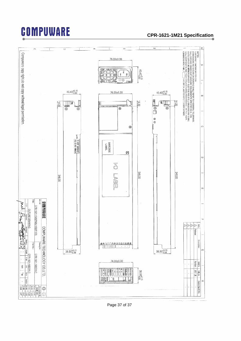
9. Mechanical

CPR-1621-1M21 Specification
Page 32 of 37
All dimensions are in mm unit.
W: 76 +/-0.5
L: 360+/-0.5
H: 40.25+/-0.5 (Front, AC inlet side), H39.5+/-0.5 (back, gold finger side)
10. Output Connector and Dimension The power supply will provide a card edge connector compatible with the backplane. See power supply mechanical drawing for dimensions. The power supply connector is a 23 pair (46 pin) edge connection type from FCI connector or equivalent.
Power and Signal Connection
Description Pin Number I/O Active Pin Length
+12V 1 Power Pin Standard
+12V 2 Power Pin Standard
Ishare 3 Analog Standard
A1 (address) 4 I/O High/Low Standard
A2 (address) 5 I/O High/Low Standard
I2C SCL 6 I/O High/Low Standard
I2C SDA 7 I/O High/Low Standard
PS ON/OFF 8 I Low Short (by 1mm)
SMBAlert 9 O (+5V) High/Low Standard
DC GOOD 10 O ( +12V ) High Standard
+12V 11 Power Pin Standard
+12V 12 Power Pin Standard
+12V 13 Power Pin Standard
+12V 14 Power Pin Standard
+12V 15 Power Pin Standard
+12V 16 Power Pin Standard
+12V 17 Power Pin Standard
+12V 18 Power Pin Standard
+12V 19 Power Pin Standard
+12V 20 Power Pin Standard
+12V 21 Power Pin Standard
+12V 22 Power Pin Standard
+12V 23 Power Pin Standard
DC Return 24 Power Pin Standard
CPR-1621-1M21 Specification
Page 33 of 37
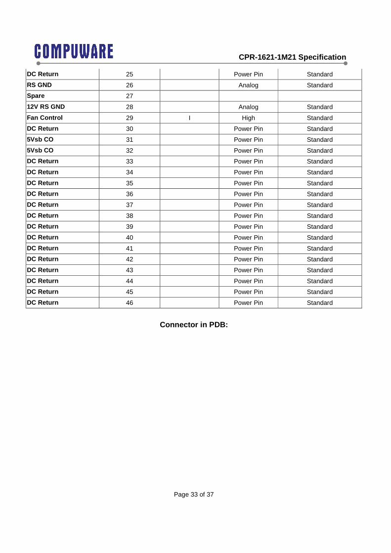
DC Return 25 Power Pin Standard
RS GND 26 Analog Standard
Spare 27
12V RS GND 28 Analog Standard
Fan Control 29 I High Standard
DC Return 30 Power Pin Standard
5Vsb CO 31 Power Pin Standard
5Vsb CO 32 Power Pin Standard
DC Return 33 Power Pin Standard
DC Return 34 Power Pin Standard
DC Return 35 Power Pin Standard
DC Return 36 Power Pin Standard
DC Return 37 Power Pin Standard
DC Return 38 Power Pin Standard
DC Return 39 Power Pin Standard
DC Return 40 Power Pin Standard
DC Return 41 Power Pin Standard
DC Return 42 Power Pin Standard
DC Return 43 Power Pin Standard
DC Return 44 Power Pin Standard
DC Return 45 Power Pin Standard
DC Return 46 Power Pin Standard
Connector in PDB:

CPR-1621-1M21 Specification
Page 34 of 37
11. MTBF and Quality Data The life requirement shall be met the following condition. And the environmental temperature is
assumed to be 25 degrees Celsius.Normal operation (at the rated input/output): 150,000h.
12. Safety 12.1 Dielectric Strength Testing (Hi-pot)
All units must pass a 1500VAC line to ground/chassis Hi-Pot test in production lines. The voltage
must be maintained at that level for a minimum of 3 seconds without failure.
12.2 Ground Continuity Testing
All units must pass a ground continuity test with less 0.1 Ohm from the ground (third wire) input
pin to the chassis.
12.3 Agency Requirements
The power supply must comply with all regulatory requirements for its intended geographical
market as computer server of Information Technology Equipment.
The power supply must meet all regulatory requirements for the intended market at the time of
manufacturing. This power supply shall have below certificates for ITE category:
CPR-1621-1M21 Specification
Page 35 of 37
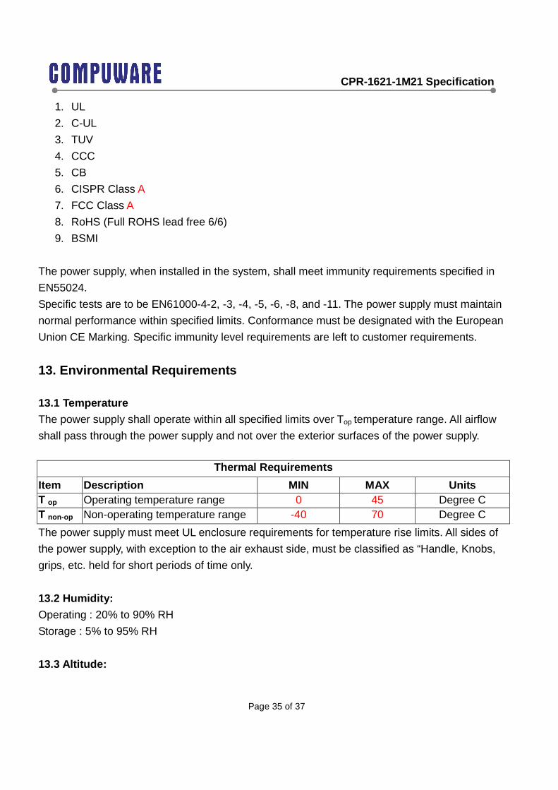
1. UL
2. C-UL
3. TUV
4. CCC
5. CB
6. CISPR Class A
7. FCC Class A
8. RoHS (Full ROHS lead free 6/6)
9. BSMI
The power supply, when installed in the system, shall meet immunity requirements specified in
EN55024.
Specific tests are to be EN61000-4-2, -3, -4, -5, -6, -8, and -11. The power supply must maintain
normal performance within specified limits. Conformance must be designated with the European
Union CE Marking. Specific immunity level requirements are left to customer requirements.
13. Environmental Requirements
13.1 Temperature
The power supply shall operate within all specified limits over Top temperature range. All airflow
shall pass through the power supply and not over the exterior surfaces of the power supply.
Thermal Requirements
Item Description MIN MAX Units T op Operating temperature range 0 45 Degree C T non-op Non-operating temperature range -40 70 Degree C
The power supply must meet UL enclosure requirements for temperature rise limits. All sides of
the power supply, with exception to the air exhaust side, must be classified as “Handle, Knobs,
grips, etc. held for short periods of time only.
13.2 Humidity:
Operating : 20% to 90% RH
Storage : 5% to 95% RH
13.3 Altitude:
CPR-1621-1M21 Specification
Page 36 of 37
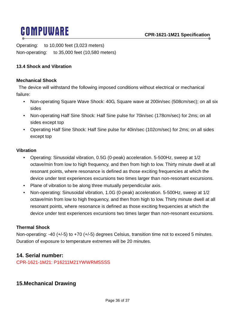
Operating: to 10,000 feet (3,023 meters)
Non-operating: to 35,000 feet (10,580 meters)
13.4 Shock and Vibration
Mechanical Shock
The device will withstand the following imposed conditions without electrical or mechanical
failure:
• Non-operating Square Wave Shock: 40G, Square wave at 200in/sec (508cm/sec); on all six
sides
• Non-operating Half Sine Shock: Half Sine pulse for 70in/sec (178cm/sec) for 2ms; on all
sides except top
• Operating Half Sine Shock: Half Sine pulse for 40in/sec (102cm/sec) for 2ms; on all sides
except top
Vibration
• Operating: Sinusoidal vibration, 0.5G (0-peak) acceleration. 5-500Hz, sweep at 1/2
octave/min from low to high frequency, and then from high to low. Thirty minute dwell at all
resonant points, where resonance is defined as those exciting frequencies at which the
device under test experiences excursions two times larger than non-resonant excursions.
• Plane of vibration to be along three mutually perpendicular axis.
• Non-operating: Sinusoidal vibration, 1.0G (0-peak) acceleration. 5-500Hz, sweep at 1/2
octave/min from low to high frequency, and then from high to low. Thirty minute dwell at all
resonant points, where resonance is defined as those exciting frequencies at which the
device under test experiences excursions two times larger than non-resonant excursions.
Thermal Shock
Non-operating: -40 (+/-5) to +70 (+/-5) degrees Celsius, transition time not to exceed 5 minutes.
Duration of exposure to temperature extremes will be 20 minutes.
14. Serial number: CPR-1621-1M21: P16211M21YWWRMSSSS
15.Mechanical Drawing
CPR-1621-1M21 Specification
Page 37 of 37


