Embed Size (px)
Citation preview
Fire Protection of Buildings Contents Section 1 — Fire extinguishing systems
Introduction
Chapter 1 — Automatic sprinklers — principles of design 1.1 General
1.2 Historical
1 Installation and design requirements
1.4 Risk categories
1.4.1 Light hazard
1.4.2 Ordinary hazards
1.4.3 High hazard
1.5 Classes of system
1.6 Design density and assumed area of maximum operation
1.7 Life safety systems
1.7.1 General
1.7.2 Requirements Chapter 2 — Automatic sprinklers — water supplies 2.1 General
2.2 Types of water supply
2.2.1 Single supply
2.2.2 Superior supply
2.2.3 Duplicate supply
2.3 Details of particular supplies
2.3.1 Town mains
2.3.2 Suction and booster pumps
2.3.3 Elevated private reservoir — minimum supply capacity
2.3.4 Gravity tank
2.3.5 Pressure tanks
(I) Sole supply
(II) Duplicate supply
2.4 Pressure and flow requirements
2.4.1 Low hazard and ordinary hazard classes
2.4.2 High hazard category
2.5 Proving of water supplies 2.6 Fire brigade inlets
Chapter 3 — Automatic sprinklers — protection systems 3.1 General
3.2 Wet pipe system
3.2.1 Types of wet pipe installations
3.3 Dry pipe system
3.3.1 Operation of the differential air valve system
3.3.2 Action of the accelerator
3.3.3 Maximum number of sprinklers
3.4 Alternate wet and dry system
3.4.1 Sprinkler heads
3.4.2 Valve assembly
3.4.3 Three-way cock
3.4.4 Other types of alternate systems
3.5 Tail-end systems (dry pipe or alternate)
3.6 Pre-action systems
3.7 Recycling systems
3.8 Deluge systems Chapter 4 — Automatic sprinklers — controls, gauges and alarms 4.1 Stop valves
4.2 Non-return valves
4.3 Drain valves and test valves
4.4 Pipe drains
4.5 Pressure gauges
4.6 Alarm devices
4.6.1 Electrically-operated alarms
4.6.2 Transmission of alarm signals to the fire brigade Chapter 5 — Automatic sprinklers — sprinkler heads 5.1 Fusible solder type
5.2 Bulb type
5.3 Sprinkler orifice sizes
5.4 Types of sprinkler head
5.4.1 General
5.4.2 Approved types
5.4.3 Conventional pattern
5.4.4 Spray pattern
5.4.5 Ceiling or flush pattern
5.4.6 Recessed and concealed pattern
5.4.7 Sidewall pattern
5.4.8 Fast-response sprinkler heads (FRS)
5.4.9 Design (a) Fusible strut type
(b) Bulb type
5.4.10 Discharge patterns
5.4.11 Water droplet size
5.4.12 Further information
5.5 Life of sprinkler heads
5.6 Protection of sprinkler in certain risks
Chapter 6 — Automatic sprinklers — general 6.1 Siting of sprinkler heads
6.2 Area covered by sprinklers
6.3 Multiple controls
6.4 Extent of sprinkler system
6.5 Firefighting in a sprinklered building
6.6 Re-setting of sprinkler systems
Chapter 7 — Protection of special risks 7.1 High-bay warehouse storage
7.1.1 General
7.1.2 Design recommendations
7.1.3 Categorisation of risks
7.2 Aircraft maintenance and assembly areas
7.2.1 Ground level sprinklers
7.2.2 Portable units
Chapter 8 — Domestic sprinkler installations 8.1 The system
8.2 Water supplies
8.3 Sprinkler heads
8.4 Sprinkler spacing and coverage
8.5 Alarms
Chapter 9 — Other installations using water 9.1 Drenchers
9.1.1 Roof drenchers
9.1.2 Wall or curtain drenchers
9.1.3 Window drenchers
9.1.4 Water supplies
9.1.5 Valves
9.1.6 Spacing of drencher heads
9.1.7 Discharge
9.1.8 Drainage
9.2 Water-spray projector systems
9.2.1 Extinction of oil fires by water
9.2.2 Cooling
9.2.3 Dilution of oxygen supplies
9.2.4 Dilution of the liquid
9.2.5 Types of system
(a) High velocity system
(I) Projectors
(II) Methods of operation
(III) Alarms
(IV) General

(b) Medium velocity systems
9.2.6 Water mist systems
9.3 Foam installations (Low expansion)
9.3.1 Foam and foam-making equipment
(a) Proportional-tank mechanical foam installation
(b) Pump-operated foam installation
(c) Pre-mixed foam installations
9.4 Foam installations (High Expansion — HX)
9.5 Foam inlets
9.6 Rising mains
9.6.1 Wet risers
9.6.2 Dry risers
9.6.3 Types to be used
9.7 Hose reels
9.7.1 Connections
9.7.2 Operation
9.8 Private hydrants
9.8.1 Connections
9.8.2 Hydrant markings
9.8.3 Outlets
9.8.4 By-pass valves
Chapter 10 — Extinguishing systems not using water 10.1 Carbon dioxide installations
10.1.1 Applications and limitations of carbon dioxide
10.1.2 Gas stored in cylinders
10.1.3 Gas stored in refrigerated tanks
10.1.4 General considerations
10.1.5 Methods of operation
(I) Total flooding systems
(II) Local application systems
10.1.6 Lock-off devices
10.1.7 Indicating and alarm devices
10.1.8 Other automatic devices
10.1.9 General safety precautions
10.1.10 Action by the fire service
10.2 Halon installations
10.3 Powder installations
10.4 Inert gas installations
Section 2 — Fire warning and Detection systems
Introduction
Chapter 11 — Automatic fire detection 11.1 Principles of automatic fire detection
11.2 Types of fire alarm and detection systems
11.2.1 Category M systems
11.2.2 Category L systems
(I) Li systems
(II) L2 systems
(III) L3 systems
(IV) L4 systems
(V) L5 systems
11.2.3 Category P systems
(I) P1 systems
(II) P2 systems
11.3 Definition of a detector
11.4 Classification of detectors
11.4.1 Analogue detector
11.4.2 Two state detector
11.4.3 Multi state detector
11.5 Successor failure of operation
11.6 Fire products
11.6.1 T of products
11.6.2 Mass transport
11.6.3 Smoke
11.6.4 Radiation
11.6.5 Heat
11.7 Conclusion
Chapter 12 — Detectors which respond to smoke 12.1 Smoke detectors
12.2 Ionisation detectors
12.3 Optical detectors
12.3.1 Light-scatter type
12.3.2 Obscuration type
12.4 Combustion gas detectors
12.5 Multi-sensor detectors
12.6 Aspirating detection system
12.7 Linear beam detector
12.8 Video detector
12.9 Conclusion
Chapter 13— Flame detectors 13.1 General
13.2 Infra-red detector
13.2.1 Fixed types
13.2.2 Scanning type
13.3 Ultra-violet detector
13.4 Conclusion

Chapter 14 — Heat detectors 14.1 General
14.2 Heat detectors using fusible alloys
14.3 Heat detectors using the principle of expansion
14.3.1 Expansion of a single metal strip
14.3.2 Expansion of a bi-metallic strip
14.3.3 Expansion of bi-metallic strip in a ‘rate-of-rise’ detector
14.3.4 Advantages and disadvantages
14.3.5 Typical rate-of-rise detector
14.3.6 Expansion of liquids
14.4 Linear heat detectors
14.4.1 General
14.4.2 Operating methods
(I) Resistivity type
(II) Insulation type
(III) Compressed gas type
14.4.3 General comment on heat detectors
Chapter 15 — Automatic fire detectors — radio-based systems 15.1 General
15.2 Safeguards
15.3 Advantages and disadvantages
15.4 Power supplies
Chapter 16 — Automatic fire detection — detector circuits 16.1 General
16.2 ‘Open’ circuit systems
16.3 ‘Closed’ circuit systems
16.4 Detector and alarm circuits
16.5 Wiring and power supplies
16.5.1 Wiring
16.5.2 Power supplies
Chapter 17 — Fire alarm operation and control 17.1 General
17.2 Zones
17.2.1 Detection zones
17.2.2 Alarm zones
17.3 Alarm signals
(a) Audible
(b) Visual
(c) Sensual
17.4 Power supplies
17.5 Control and indicating equipment
17.6 Faults
(a) Normal condition
(b) Pre-alarm level
17.7 Fire level
17.8 Silence alarms and reset
17.9 Fault level
17.10 Monitoring the system
17.11 Maintenance
17.12 Visual displays
17.13 Examples of control and indicating equipment
17.13.1 3-zone type detection system
(I) Fire condition
(II) Reset
(III) Fault
(IV) Other interfaces
17.13.2 Multi zone type with microprocessor
(I) Normal level
(II) Pre-alarm level
(III) Fire level
(IV) Fault condition
(V) Maintenance
(VI) Additional facilities
(VII) False alarms
17.14 Alarm receiving centres
17.14.1 General
17.14.2 Connections from premises (FAS) to ARCs
17.14.3 Connections from ARC to fire brigade controls
17.14.4 Methods of transmission — protected premises to ARC
(I) Private wire
(II) Omnibus circuits
(III) ARC satellites
(IV) Digital communications
17.14.5 Methods of transmission
(I) Private wire
(II) 999 facilities
(III) Ex-directory number
(IV) Administrative telephone number
Chapter 18 — Choice of detector and detector positioning 18.1 General
18.2 Smoke detectors
18.2.1 General
18.2.2 Area
18.2.3 Heat inversion
18.2.4 Air movement
18.2.5 Voids
18.2.6 Walls, beams and galleries
18.2.7 Corridors
18.2.8 Staircases, shafts, etc.
18.2.9 Ducts
18.2.10 Electronic equipment installations
18.3 Heat detectors
18.3.1 General
18.3.2 Positioning
(I) Height
(II) Area
(III) Sloping ceilings
(IV) Beams and similar construction
Chapter 19 Manually-operated fire alarms 19.1 Manual systems
19.2 Manual/electric systems
19.3 Miscellaneous
19.4 Restricted alarms
19.5 Smoke alarms
Section 3 — Smoke control and fire venting systems
Introduction
Chapter 20 — Smoke ventilation 20.1 Purposes of ventilation in single storey buildings
20.1.1 Prevention of smoke logging
20.1.2 Prevention of spread of fire
20.1.3 Vent construction
20.1.4 Vent operation
(a) Heat detectors
(b) Smoke detectors
20.1.5 Vent position
20.1.6 Area of venting
20.1.7 Air inlets
20.2 Other factors
20.2.1 Screens
(a) Screen construction
(b) Screen effect
20.2.2 Smoke and fire curtains
(a) Smoke curtains
(b) Fire curtains
20.2.3 Sprinklers
20.2.4 Additional controls

Chapter 21 — Smoke and heat exhaust ventilation systems (SHEVS) 21.1 Purposes of venting in complex buildings
21.2 Types of smoke and heat exhaust ventilation systems
21.2.1 Replacement air inlets
21.2.2 Performance of system
21.2.3 use of smoke and heat exhaust ventilation systems
21.2.4 Design of the system
21.2.5 System capacity
21.2.6 Operation of smoke and heat exhaust ventilation systems
21.2.7 Conclusion
Chapter 22 — Application of smoke and heat control systems 22.1 Smoke control in Shopping Complexes
22.1.1 General
22.1.2 Basic principles of control
22.1.3 Control of smoke
22.1.4 Function and design of the reservoir
22.1.5 Effects on people
22.1.6 Removal of hot smoke and gases
(a) Rate of exhaust
(b) Wind effects
22.1.7 Sprinklers
22.1.8 Automatic fire detectors
22.1.9 Conclusion
22.2 Atria
22.2.1 Smoke control systems
22.2.2 Design of systems
(I) Smoke systems
(II) Pressure differential systems
(III) Choice of system
22.2.3 Conclusion
Chapter 23 — Ventilation in multi-storey buildings 23.1 General
23.1.1 Ductwork in buildings
23.1.2 Systems used
23.1.3 Air conditioning systems
23.1.4 Plant rooms
23.1.5 Components of systems
(a) Dry fitters
(b) Viscous filters
(c) Electrostatic fitters
23.1.6 The ducting
(a) Ducting design
(b) Shunt ducts
(c) Duct construction
23.1.7 Fire spread in ducting
(a) Insulating material
(b) Flexible joints and connections
(I) Flexible joints
(II) Flexible connections
23.1.8 Exterior risks
23.1.9 Air intakes
23.1.10 Fire dampers
(a) Mechanical
(b) Intumescent
(c) Inspection and maintenance
(d) Multiple controls
23.1.11 Fire stopping of shafts (encased ducting)
23.1.12 Re-circulation systems
23.1.13 Firefighting control
24.1 General
24.1.1 Smoke movement
24.1.2 Air movement
24.1.3 Pressurisation
24.1.4 Requirements of a pressurisation system
(a) Pressure required
(b) Leakage paths
(I) Initial leakage path
(II) Final leakage path
24.1.5 Firefighting
24.1.6 Advice and further information
Acknowledgements

Section 1 – Fire extinguishing systems Fire Protection of Buildings
Introduction
Fixed systems of pipework using only water as the extinguishing medium have proved efficient in the protection of buildings, and many other classes of risk, against extensive damage resulting from out breaks of fire. Such systems can be divided into three main classes — automatic sprinklers, drenchers and water spray projector systems.
Automatic sprinklers were originally used only to protect property and many such installations can be found today. However, increasingly the value of sprinklers as a means of life protection has been recognised. The installation of suitably designed sprinkler systems have allowed designers and architects greater scope in creating buildings that would otherwise not meet basic life safety fire standards.
Sprinklers are generally installed within a building structure and are usually operated by heat when a fire occurs. However, in some circumstances sprinklers can be found outside of buildings where it is considered that a fire in certain parts, such as water disposal units, may put the building at risk.
A simple form of sprinkler technology has been developed for use in domestic premises. Whilst the take up of sprinkler protection in housing is slow, a sprinkler system can substantially improve the chances of occupants surviving a fire in their home whilst drastically reducing fire loss.
Drenchers, which can be automatically or manually operated, are normally fined outside a building in order to protect it from a fire in nearby property. The use of a drencher on the fire curtain in theatres is an example where the fire resistance of a relatively flimsy material can be enhanced to good effect.
Water spray projector systems are automatic and specially designed for extinguishing fires involving oils, flammable liquids or other special risks.
Automatic sprinklers are dealt with in Chapters 1—6, other installations using water in Chapter 8. Chapter 10 describes installations not using water e.g. CO2 and powder These are designed for the protection of risks for which water is unsuitable as an extinguishing medium. New systems using halon or other ozone depleting vaporising liquids have been banned by virtue of the Montreal Agreement signed up to by the United Kingdom. Except in very special circumstances, existing systems using halon are being replaced with more environmentally friendly systems.
Special systems are sometimes designed for a specific risk and are, usually, highly sophisticated and two examples are described in Chapter 7,
It is important to ensure that effective consultation takes place with the Local Authority, Water Authorities, Insurance bodies etc. (see BS 5306 Part 2 Clause 3.1)
Fire Protection of Buildings
Chapter 1 — Automatic sprinklers — principles of design
1.1 General Since a most important principle of successful fire extinction is to attack an outbreak immediately, it follows that any device which can detect a fire automatically and then control or extinguish it with the minimum loss, must he of great value. Automatic sprinkler systems using water as the extinguishing medium have been universally adopted as one means of achieving this purpose.
Basically an automatic sprinkler installation comprises of a system of pipes erected at, or near, the ceiling on each floor of a building and connected, through controlling valves, to one or more water supplies. At intervals on the pipework are sealed outlets called sprinkler heads. These incorporate a device whereby a rise in temperature to a predetermined limit causes the sprinkler to open and water to be discharged in the form of a spray over an area of the floor below. The sprinklers are so spaced that the extremities of the discharge pattern from any two sprinklers overlap, leaving no part of the floor unprotected.
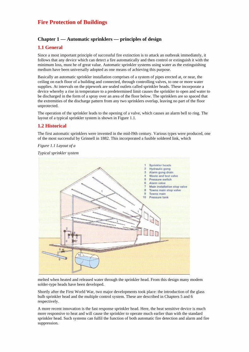
The operation of the sprinkler leads to the opening of a valve, which causes an alarm bell to ring. The layout of a typical sprinkler system is shown in Figure 1.1.
1.2 Historical The first automatic sprinklers were invented in the mid-l9th century. Various types were produced, one of the most successful by Grinnell in 1882. This incorporated a fusible soldered link, which
Figure 1.1 Layout of a
Typical sprinkler system
melted when heated and released water through the sprinkler head. From this design many modem solder-type heads have been developed.
Shortly after the First World War, two major developments took place: the introduction of the glass bulb sprinkler head and the multiple control system. These are described in Chapters 5 and 6 respectively.
A more recent innovation is the fast response sprinkler head. Here, the heat sensitive device is much more responsive to heat and will cause the sprinkler to operate much earlier than with the standard sprinkler head. Such systems can fulfil the function of both automatic fire detection and alarm and fire suppression.
1.3 Installation and design requirements In England and Wales the Approved Document B states that retail buildings over 2000m should be sprinklered, compartmented or designed using another acceptable method. Technical Standards in Scotland differ from those in England and Wales. Fire authorities can require maintenance and testing of sprinkler installations where the system is taken into account when granting a fire certificate under the Fire Precautions Act, 1971.
Where sprinkler systems are installed as a requirement/recommendation by the fire service, then the requirement/recommendation must satisfy that the system to be installed is fit for purpose, that is, that a correctly designed system is installed taking account of the hazard.
Insurance companies encourage the installation of sprinkler systems, specifically where arson is considered within a fire risk analysis. Buildings fitted with sprinkler systems to an approved standard sometimes qualify for substantial reductions in premiums for property so protected. They, through the Loss Prevention Council (LPC), lay down the minimum standards necessary.
Sprinkler systems are designed in accordance with:
(I) British Standard 5306: Part 2 (1990).
(II) LPC rules for Automatic Sprinkler Installations.
These two documents are now synonymous and any amendment to one is reflected in the other.
Further reference in this Manual will be to ‘the BS/LPC Rules’.
The BS/LCP Rules detail standards for sprinkler systems designed for life safety. Sprinkler systems fall into various hazard groups according to the use of the building. Each class of system is designed to produce a certain density of water discharge over a predetermined area for a given period of time depending on the expected area of fire development in that particular occupancy (see Section 6).
Sprinkler installations are used to protect a very wide range of premises and there are very few buildings which are totally unsuitable for sprinklers. Where parts of a building contain materials or processes for which water would be unsuitable as an extinguishing medium, these areas can be isolated by fire resisting construction and the remainder protected by sprinklers.
The terms (a) ‘high rise’ and (b) ‘low rise’ systems are used to describe systems where:
(a) The highest sprinkler is more than 45m above the lowest sprinkler or the sprinkler pumps, whichever is the lowest and;
(b) The highest sprinkler is not more than 45m above ground level or the sprinkler pump.
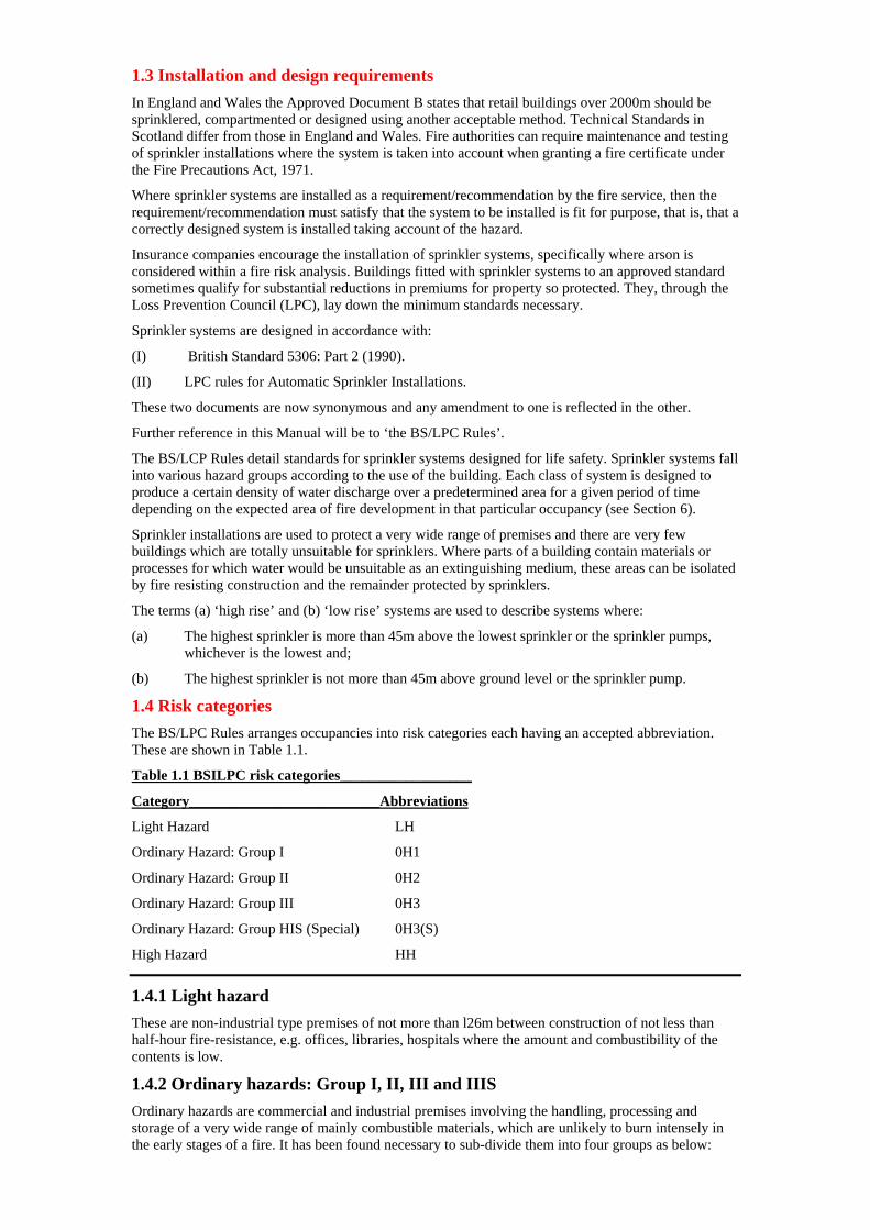
1.4 Risk categories The BS/LPC Rules arranges occupancies into risk categories each having an accepted abbreviation. These are shown in Table 1.1.
Table 1.1 BSILPC risk categories__________________
Category__________________________Abbreviations
Light Hazard LH
Ordinary Hazard: Group I 0H1
Ordinary Hazard: Group II 0H2
Ordinary Hazard: Group III 0H3
Ordinary Hazard: Group HIS (Special) 0H3(S)
High Hazard HH
1.4.1 Light hazard These are non-industrial type premises of not more than l26m between construction of not less than half-hour fire-resistance, e.g. offices, libraries, hospitals where the amount and combustibility of the contents is low.
1.4.2 Ordinary hazards: Group I, II, III and IIIS Ordinary hazards are commercial and industrial premises involving the handling, processing and storage of a very wide range of mainly combustible materials, which are unlikely to burn intensely in the early stages of a fire. It has been found necessary to sub-divide them into four groups as below:
Group Examples
Group I Breweries, dairies and restaurants
Group II Engineering works, garages, medium size retail shops
Group Ill Soap factories, sugar refineries, air craft factories
Group Ill Film and television studios, cotton mills, match factories.
1.4.3 High Hazard This category covers commercial and industrial occupancies having abnormal fire loads:
(II) Where materials handled or processed are mainly of an extra hazardous nature likely to develop rapid and intensely-burning fires.
(II) Those involving high-piled storage.
According to the hazardous nature of the stock and the height of the storage, those included in (II) above are sub-divided into four categories:
Category I Process high hazards
Category II High-piled storage hazards
Category Ill Potable spirit storage hazards
Category TV Oil and flammable liquids hazards
The term ‘storage’ includes the warehousing or temporary depositing of goods or materials.
1.5 Classes of system Three classes of sprinkler system have been developed to suit the above risk categories:
(I) Light Hazard system
(II) Ordinary Hazard system
(III) High Hazard system.
Pipework for two or more different types of hazard system may be connected to a common set of control valves, provided the total number of sprinklers does not exceed the permitted maximum. Each of these systems is designed to give the appropriate density of discharge over an assumed area of maximum’ operation (AMAO) in the highest and most hydraulically remote parts of a protected building.
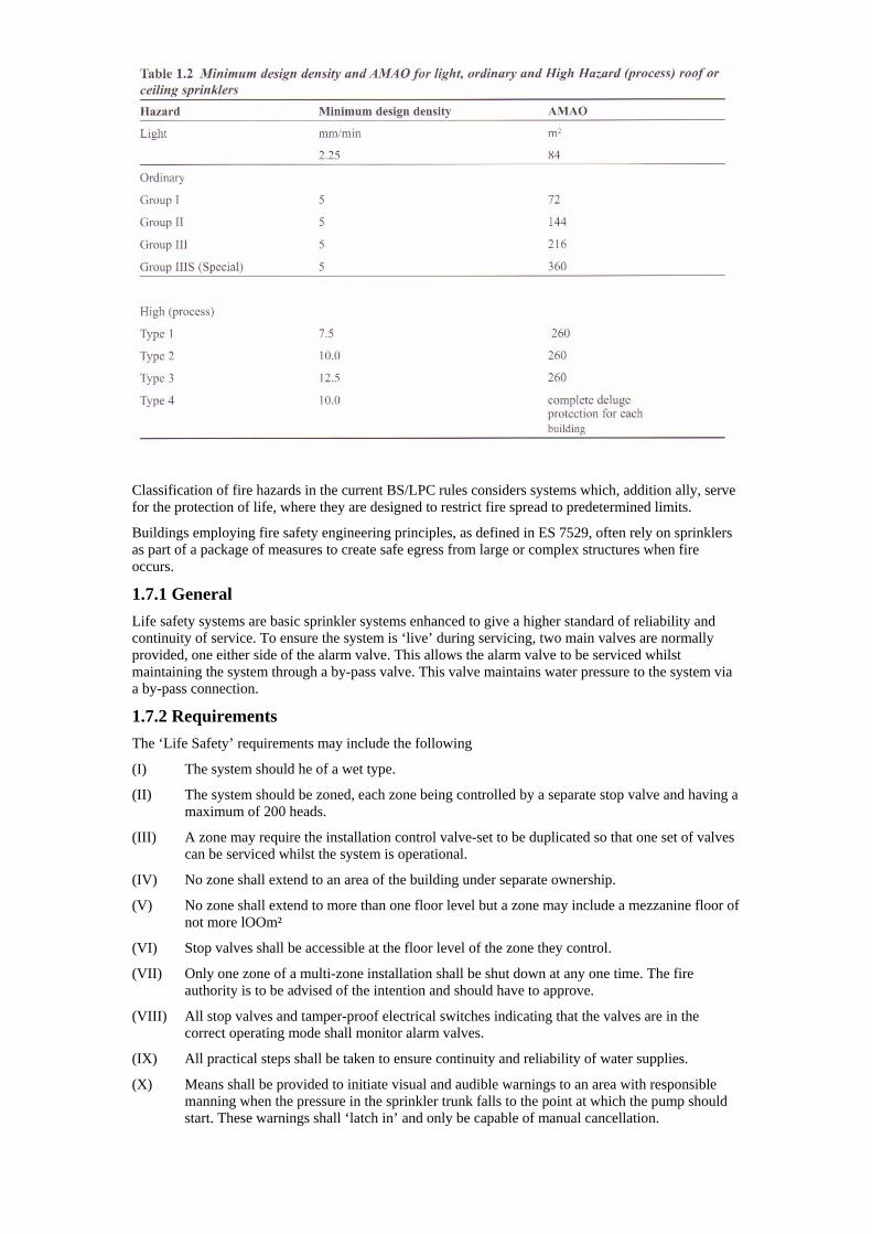
1.6 Design density and assumed area of maximum operation The amount of water required to control or extinguish a fire is called the minimum design density and will depend, among other criteria, on the type of hazard involved. Minimum design density is pre-set according to the recommendations of the BS/LPC Rules and is specified for each hazard class.
The standard requires that the minimum design density of discharge of water in mm/min from a particular group of sprinklers be not less than a given value (see Table 1.2). This group of sprinklers -usually numbering four or more - is that which is most hydraulically remote from the water supply and constitutes part of a ‘larger group’ of sprinklers discharging simultaneously.
The ‘larger group’ forms the ‘area of assumed maximum operation’ (AMAO). This is the maxi mum area over which it is assumed, for design purposes, sprinklers will operate in a fire. The hydraulically most removed AMAO is used to calculate design density.
1.7 Life safety systems The use of sprinkler installations in the saving of lives by preventing the development of fire is well understood. Today, sprinkler systems have played an increasing role in life safety fire precautions.
Classification of fire hazards in the current BS/LPC rules considers systems which, addition ally, serve for the protection of life, where they are designed to restrict fire spread to predetermined limits.
Buildings employing fire safety engineering principles, as defined in ES 7529, often rely on sprinklers as part of a package of measures to create safe egress from large or complex structures when fire occurs.
1.7.1 General Life safety systems are basic sprinkler systems enhanced to give a higher standard of reliability and continuity of service. To ensure the system is ‘live’ during servicing, two main valves are normally provided, one either side of the alarm valve. This allows the alarm valve to be serviced whilst maintaining the system through a by-pass valve. This valve maintains water pressure to the system via a by-pass connection.
1.7.2 Requirements The ‘Life Safety’ requirements may include the following
(I) The system should he of a wet type.
(II) The system should be zoned, each zone being controlled by a separate stop valve and having a maximum of 200 heads.
(III) A zone may require the installation control valve-set to be duplicated so that one set of valves can be serviced whilst the system is operational.
(IV) No zone shall extend to an area of the building under separate ownership.
(V) No zone shall extend to more than one floor level but a zone may include a mezzanine floor of not more lOOm²
(VI) Stop valves shall be accessible at the floor level of the zone they control.
(VII) Only one zone of a multi-zone installation shall be shut down at any one time. The fire authority is to be advised of the intention and should have to approve.
(VIII) All stop valves and tamper-proof electrical switches indicating that the valves are in the correct operating mode shall monitor alarm valves.
(IX) All practical steps shall be taken to ensure continuity and reliability of water supplies.
(X) Means shall be provided to initiate visual and audible warnings to an area with responsible manning when the pressure in the sprinkler trunk falls to the point at which the pump should start. These warnings shall ‘latch in’ and only be capable of manual cancellation.
(XI) On indicator panels, audible alarms may be silenced after the system has operated, but the visual alarm signal shall remain until the installation has been reset to its normal operational position.
In theatres and similar buildings, where a fire break curtain is protected by open drenchers or sprinklers operated by a quick opening valve, the water supply to these should not be taken from that supplying the automatic sprinkler installation.
Chapter 2— Automatic sprinklers — water supplies 2.1 General Automatic sprinkler systems must be provided with a suitable and acceptable water supply. It must have a pressure and flow characteristic not less than that specified in the BS/LPC Rules. It must be automatic, thoroughly reliable and not subject to either frost or drought conditions that could seriously affect the supply. The supply should be under the control of the occupier of the building containing the installation or, where this is not practicable, the right of use of the supply must be suitably guaranteed.
Close consultation must take place with Water UK and/or the local suppliers, specifically to identify what supplies are available which will impact on the system design.
The water must be free from any matter in suspension, which would be liable to cause accumulation in the system pipework. The use of salt or brackish water is not normally allowed. In special circum stances, where there is no suitable fresh water source available, consideration may be given to the use of salt or brackish water provided that the installation is normally charged with fresh water
2.2 Types of water supply Water supplies are graded into three categories:
Single, superior and duplicate.
2.2.1 Single supply a single supply must be: (I) A town main capable of supplying the necessary pressure and flow requirements.
(II) An automatic booster pump drawing water from the town main capable of supplying the necessary pressure and flow requirements.
(III) An automatic suction pump drawing water either from a suction tank complying with BS/LPC Rules or a virtually inexhaustible source, i.e. river, lake, canal.
2.2.2 Superior supply These will vary according to whether the system is a low’ or ‘high’ rise and will depend on the occupancy hazard rating.
For low rise systems — a superior supply shall be:
(I) A town main; or
(II) Two automatic suction pumps from a suction tank; or
(III) Two automatic booster pumps; or
(IV) An elevated private reservoir; or
(V) A gravity tank; or
(VI) A pressure tank (for low hazard or ordinary hazards Group I occupancies only).
For high rise systems — a superior supply shall be:
(I) A gravity tank; or
(II) An automatic suction pump arrangement in which each installation is served by either a separate pump or separate stage of a multi stage pump.
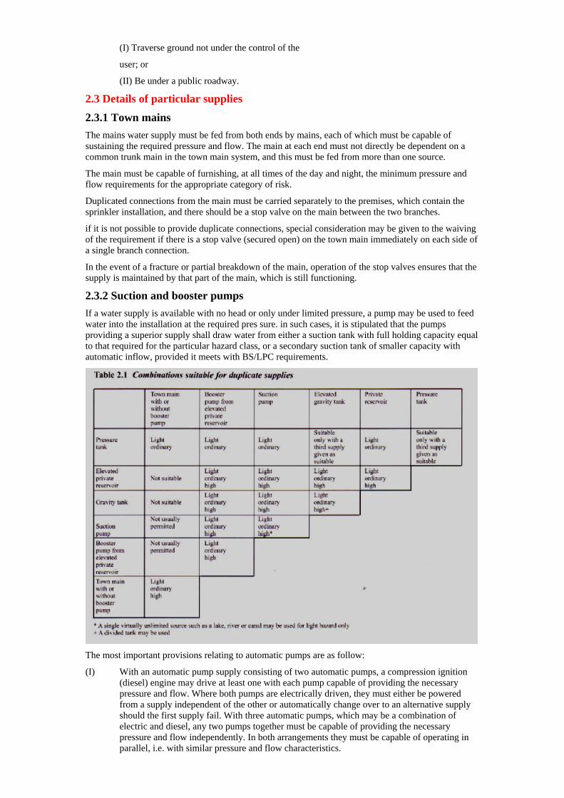
2.2.3 Duplicate supply A duplicate supply shall include at least one of the suitable combinations given in Table 2.1 with the supply pipes from each source joined into a common trunk main as close as possible to the protect ed premises.
A common trunk main may serve more than one installation but shall not:
(I) Traverse ground not under the control of the
user; or
(II) Be under a public roadway.
2.3 Details of particular supplies
2.3.1 Town mains The mains water supply must be fed from both ends by mains, each of which must be capable of sustaining the required pressure and flow. The main at each end must not directly be dependent on a common trunk main in the town main system, and this must be fed from more than one source.
The main must be capable of furnishing, at all times of the day and night, the minimum pressure and flow requirements for the appropriate category of risk.
Duplicated connections from the main must be carried separately to the premises, which contain the sprinkler installation, and there should be a stop valve on the main between the two branches.
if it is not possible to provide duplicate connections, special consideration may be given to the waiving of the requirement if there is a stop valve (secured open) on the town main immediately on each side of a single branch connection.
In the event of a fracture or partial breakdown of the main, operation of the stop valves ensures that the supply is maintained by that part of the main, which is still functioning.
2.3.2 Suction and booster pumps If a water supply is available with no head or only under limited pressure, a pump may be used to feed water into the installation at the required pres sure. in such cases, it is stipulated that the pumps providing a superior supply shall draw water from either a suction tank with full holding capacity equal to that required for the particular hazard class, or a secondary suction tank of smaller capacity with automatic inflow, provided it meets with BS/LPC requirements.
The most important provisions relating to automatic pumps are as follow:
(I) With an automatic pump supply consisting of two automatic pumps, a compression ignition (diesel) engine may drive at least one with each pump capable of providing the necessary pressure and flow. Where both pumps are electrically driven, they must either be powered from a supply independent of the other or automatically change over to an alternative supply should the first supply fail. With three automatic pumps, which may be a combination of electric and diesel, any two pumps together must be capable of providing the necessary pressure and flow independently. In both arrangements they must be capable of operating in parallel, i.e. with similar pressure and flow characteristics.
(II) Pumps should be housed at ground level, either in a separate incombustible building or in a room in the same building protected by a 2-hour fire resisting-structure. The room should be directly accessible from the out side and should be as small as practicable, to discourage it being used for other purposes. The building or room containing the pumps should be maintained at a temperature not below 4°C.
In the ease of diesel pump rooms, the room should be well ventilatcd, sprinklered and maintained at a minimum temperature of 10°C.
(III) Automatic priming equipment must be provided where necessary to ensure that the pumps will be fully primed with water at all times.
(IV) The performance characteristics of the pumps should be such that the pressure falls progressively with the rate of demand. They must be capable of providing the rate of flow and pressure required at the highest and most remote parts of the protected premises. The output must be so controlled that there is not an excessive rate of discharge at the lowest level in areas close to the installation valves. To meet these conditions pumps must have performance characteristics complying with the requirements laid down.
(V) Where permitted by the water authority, a pump may draw directly from a town main, provided the latter is capable of supplying water at all times at the maximum rated out put of the pump.
(VI) The pump should be hilly operational within 30 seconds after starting.
(VII) The pump should have a direct drive and must start automatically. Means should be provided for manual starting and once start ed the pump must run continuously until stopped manually.
(VIII) Where an automatic pump forms the sole supply, a fall in water pressure in the sprinkler system, which is intended to initiate the automatic starting of the pump, shall at the same time provide a visual and audible alarm at some suitable installation, e.g. in the gate- house or by the installation control valves.
(IX) A test for automatic starting of the pump must be carried out weekly.
(X) Pumps must be driven either by an electrical motor or an approved compression ignition type of engine. The electric supply must be obtained from a reliable source, preferably from a public supply. Where a compression engine is used, provision must be made for two separate methods of engine starting, i.e. automatic or manual control, although a single starter motor is acceptable.
(XI) Any switches to the electric power feed to motors must be clearly labelled: ‘Sprinkler pump motor supply — not to be switched off in the event of fire’.
2.3.3 Elevated private reservoir — minimum supply capacity This is defined as similar to a ground reservoir but situated at a higher level than the premises to be protected. Certain conditions regarding capacity must be complied with before this type of reservoir can be used as a source of supply to a sprinkler installation. The minimum capacity ranges from 9m³- 875m³ depending on the class of system installed; this is on the understanding that the stored water is used entirely for the sprinkler system.
Where such reservoirs serve other than sprinkler installations, e.g. water for trade and domestic purposes, there must be a constant capacity of at least:
• 500m’ in light hazard categories
• 1,000m in ordinary hazard categories
• 1,000m plus additional storage capacity of between 223 in High Hazard categories, depending whether the sprinkler sys tern is wet or alternate.
In certain cases smaller capacities may be accept ed but only with the express approval of the LPC.
2.3.4 Gravity tank A gravity tank is defined as a purpose built container. It is erected on the site of the protected premises at such a height as to provide the requisite pressure and flow condition at the installation valves. The tank must be adequately protected against freezing and, where it is not enclosed with in a tower, the top must he covered so as to exclude daylight and solid matter.
The main provisions are:
(I) The tank must have a minimum capacity of 9m for the light hazard class rising to
1,095m for the High Hazard. Should the capacity of the tank exceed these requirements, it is permissible to draw upon the surplus for other purposes by means of a side-outlet pipe, which must be positioned above the level of the quantity to he reserved for the sprinkler installation.
(II) The quantity of the water required for the sprinkler installation must be automatically maintained. If the tank forms part of the sole supply to the system, the supply to the tank must he capable of refilling it to the required capacity within six hours.
(III) The use of one tank to supply installations in two or more buildings under separate owner ship is not allowed.
(IV) The tank must be fitted with a depth indicator, a permanent ladder or stairway to permit access and the water must be kept clean and free from sediment.
2.3.5 Pressure tanks A pressure tank is a cylindrical steel vessel with convex ends containing water under pressure.
The pressure tank is an acceptable superior water supply for not more than one sprinkler system of Low Hazard or Ordinary Hazard Group I categories only, provided that:
(a) the water capacity is not less than:
• Sole supply:
(a) 7m³ for Low Hazard
(b) 23m³ for Ordinary Hazard Group I
• Duplicate supply:
(a) 7m³ for Low Hazard
(b) 15m³ for Ordinary Hazard Group I
(2) there is an approved arrangement for maintaining automatically the required air pres sure and water level into the tank under non-fire conditions.
The general requirements for a pressure tank arc:
(I) It must be housed in a readily acceptable position in a sprinkler protected building of incombustible construction used for no other purpose. The tank must be adequately protected against mechanical damage. The temperature of the room should be maintained above 40°C.
(II) When used as a single water supply, the tank must he provided with an approved arrangement for maintaining automatically the required air pressure and water level in the tank under non-fire conditions. The arrangement should include an approved warning system to indicate failure of the devices to restore the correct pressure and water level. This arrangement is also advocated in cases where the tank provides the duplicate supply.
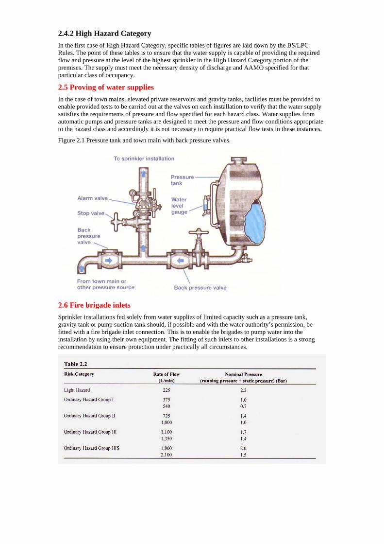
(III) The tank must be fitted with air pressure gauges and a gauge glass to show the level of the water. Stop valves and back pressure valves must be provided on both the water and air supply connections to the tank and they must be fitted as close to the tank as possible (Figure 2.1).
(IV) Where a pressure tank forms the sole supply to the installation, connections are not allowed to be taken from the supply for any purpose other than sprinklers. If it forms one source of duplicate supply, a pipe not exceeding 50mm may be taken from the combined water supply main to supply hydraulic hose reels for firefighting purposes only, subject to the pressure being replenished automatically as in (II) above.
The maximum standing air pressure for pressure tanks is 10 bar. The air capacity should not be less than one third of the capacity of the tank when full.
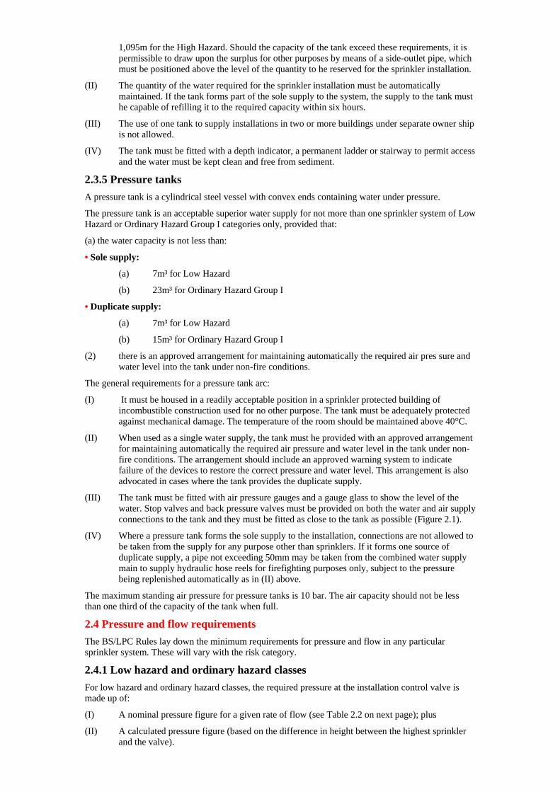
2.4 Pressure and flow requirements The BS/LPC Rules lay down the minimum requirements for pressure and flow in any particular sprinkler system. These will vary with the risk category.
2.4.1 Low hazard and ordinary hazard classes For low hazard and ordinary hazard classes, the required pressure at the installation control valve is made up of:
(I) A nominal pressure figure for a given rate of flow (see Table 2.2 on next page); plus
(II) A calculated pressure figure (based on the difference in height between the highest sprinkler and the valve).
2.4.2 High Hazard Category In the first case of High Hazard Category, specific tables of figures are laid down by the BS/LPC Rules. The point of these tables is to ensure that the water supply is capable of providing the required flow and pressure at the level of the highest sprinkler in the High Hazard Category portion of the premises. The supply must meet the necessary density of discharge and AAMO specified for that particular class of occupancy.
2.5 Proving of water supplies In the case of town mains, elevated private reservoirs and gravity tanks, facilities must be provided to enable provided tests to be carried out at the valves on each installation to verify that the water supply satisfies the requirements of pressure and flow specified for each hazard class. Water supplies from automatic pumps and pressure tanks are designed to meet the pressure and flow conditions appropriate to the hazard class and accordingly it is not necessary to require practical flow tests in these instances.
Figure 2.1 Pressure tank and town main with back pressure valves.
2.6 Fire brigade inlets Sprinkler installations fed solely from water supplies of limited capacity such as a pressure tank, gravity tank or pump suction tank should, if possible and with the water authority’s permission, be fitted with a fire brigade inlet connection. This is to enable the brigades to pump water into the installation by using their own equipment. The fitting of such inlets to other installations is a strong recommendation to ensure protection under practically all circumstances.
Chapter 3— Automatic sprinklers — protection systems 3.1 General According to the BS/LPC Rules a sprinkler installation should be based on one of the following main types:
• Wet pipe system
• Dry pipe
• Alternate (wet and dry pipe)
• Life safety
• Pre-action
• Recycling
• Deluge
Systems based on the first two types above may also include extensions of an additional type as:
• Tail-end alternate
• Tail-end dry type
3.2 Wet pipe system In this type of system, all the pipes that lead from the water supplies through the various controlling valves to the sprinkler heads throughout the building are kept permanently filled with water. Wet pipe systems are installed in premises where there is no danger, at any time, of the water in the pipes freezing. The principle controls of such a system are:
(I) A stop valve on each separate source of supply.
(II) A non-return valve on each source of supply. (iii) An installation main stop valve to cut off the flow of water to the system after a head has opened and the fire has been extinguished.
(IV) The alarm valve has two junctions,
(a) on actuation of a sprinkler head it allows the valve to open, due to a drop in pres sure, and lets water flow into the system from the main supply, and
(b) A flow is permitted to the water flow alarm to indicate the system has activated.
(V) A test and drain valve, used for testing the water flow of the installation and to empty the system when necessary. The size of this valve is 40mm in low hazard installations and 50mm in both ordinary hazard and high hazard installations.
3.2.1 Types of wet pipe installations In Figure 3.1, a typical wet pipe installation is shown and it can be seen that there are two sources of supply, one from the town main (1) and the other from a secondary source supply (2). Both are fitted with stop valves and nornreturn valves to ensure that water from either supply will not flow into the other. These supplies unite in the main supply pipe (3), which is fitted with a main stop valve (4).
Above the main stop valve is an alarm valve (5) from which a pipe is led off to the alarm motor and gong (6). When the alarm valve functions some water passes through the annular groove in the alarm valve seating to the water turbine causing it to rotate and the clapper to strike the gong.
Adjacent to the alarm valve there is a test and drainpipe (7) and the discharge from the pipe is controlled by a test and drain valve (8).
There are three gauges:
(I) Gauge (9) showing the pressure in the installation above the main stop and alarm valves.
(II) Gauge (10) showing the pressure of the sup ply below the main stop valves.
(III) Gauge (11), which shows pressure in the town main.
Figure 3.] A wet pipe system showing the main valve and gauges.
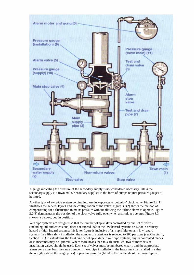
A gauge indicating the pressure of the secondary supply is not considered necessary unless the secondary supply is a town main. Secondary supplies in the form of pumps require pressure gauges to he fitted.
Another type of wet pipe system coming into use incorporates a ‘butterfly’ clack valve. Figure 3.2(1) illustrates the general layout and the configuration of the valve. Figure 3.2(2) shows the method of compensating for a fluctuation in mains pressure without allowing the turbine alarm to operate. Figure 3.2(3) demonstrates the position of the clack valve fully open when a sprinkler operates. Figure 3.3 show-s a valve-group in position.
Wet pipe systems are designed so that the number of sprinklers controlled by one set of valves (including tail-end extensions) does not exceed 500 in the low hazard systems or 1,000 in ordinary hazard or high hazard systems; this latter figure is inclusive of any sprinkler on any low hazard systems. In a life safety installation the number of sprinklers is reduced to 200 per zone (see Chapter 1, Section 1.6.) in calculating the total number of sprinklers in wet pipe systems, any in concealed places or in machines may be ignored. Where more heads than this are installed, two or more sets of installation valves should be used. Each set of valves must be numbered clearly and the appropriate alarm gong must bear the same number. In wet pipe installations, the heads may be installed in either the upright (above the range pipes) or pendant position (fitted to the underside of the range pipes).
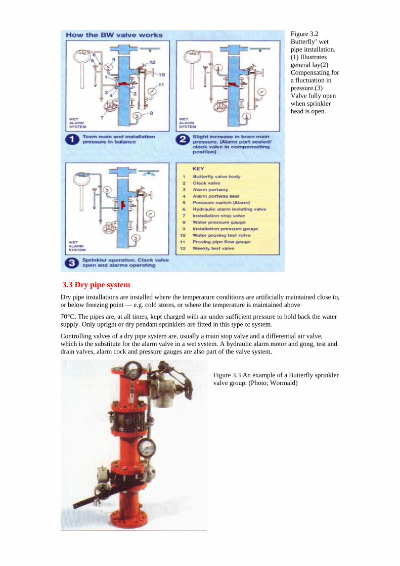
Figure 3.2 Butterfly’ wet pipe installation. (1) Illustrates general lay(2) Compensating foa fluctuation in pressure.(3) Valve fully open when sprinkler head is open.
r
3.3 Dry pipe system
Dry pipe installations are installed where the temperature conditions are artificially maintained close to, or below freezing point — e.g. cold stores, or where the temperature is maintained above
70°C. The pipes are, at all times, kept charged with air under sufficient pressure to hold back the water supply. Only upright or dry pendant sprinklers are fitted in this type of system.
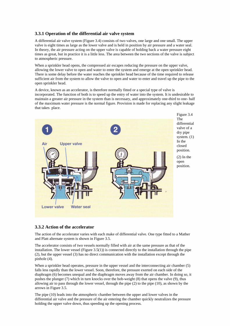
Controlling valves of a dry pipe system are, usually a main stop valve and a differential air valve, which is the substitute for the alarm valve in a wet system. A hydraulic alarm motor and gong, test and drain valves, alarm cock and pressure gauges are also part of the valve system.
Figure 3.3 An example of a Butterfly sprinkler valve group. (Photo; Wormald)
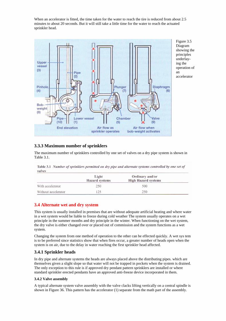
3.3.1 Operation of the differential air valve system A differential air valve system (Figure 3.4) consists of two valves, one large and one small. The upper valve is eight times as large as the lower valve and is held in position by air pressure and a water seal. In theory, the air pressure acting on the upper valve is capable of holding back a water pressure eight times as great, but in practice it is a little less. The area between the two sections of the valve is subject to atmospheric pressure.
When a sprinkler head opens, the compressed air escapes reducing the pressure on the upper valve, allowing the lower valve to open and water to enter the system and emerge at the open sprinkler head. There is some delay before the water reaches the sprinkler head because of the time required to release sufficient air from the system to allow the valve to open and water to enter and travel up the pipe to the open sprinkler head.
A device, known as an accelerator, is therefore normally fitted or a special type of valve is incorporated. The function of both is to speed up the entry of water into the system. It is undesirable to maintain a greater air pressure in the system than is necessary, and approximately one-third to one- half of the maximum water pressure is the normal figure. Provision is made for replacing any slight leakage that takes place.
Figure 3.4 The differential valve of a dry pipe system. (1) In the closed position.
(2) In the open position.
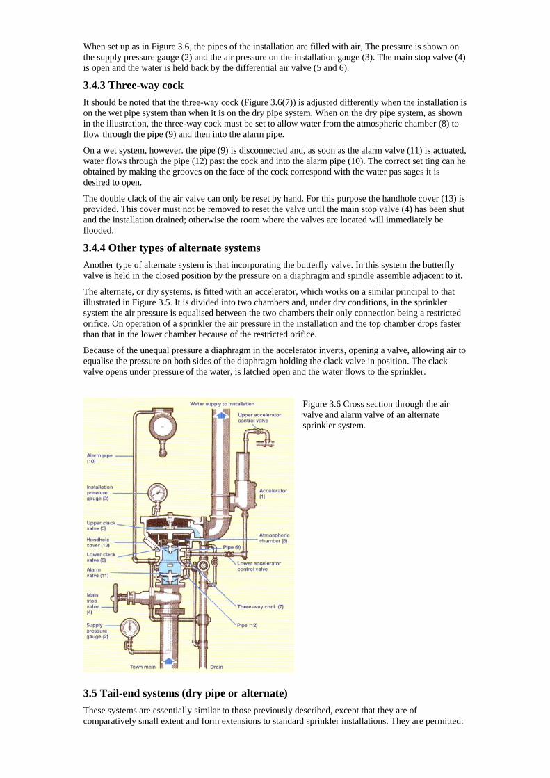
3.3.2 Action of the accelerator The action of the accelerator varies with each make of differential valve. One type fitted to a Mather and Platt alternate system is shown in Figure 3.5.
The accelerator consists of two vessels normally filled with air at the same pressure as that of the installation. The lower vessel (Figure 3.5(1)) is connected directly to the installation through the pipe (2), but the upper vessel (3) has no direct communication with the installation except through the pinhole (4).
When a sprinkler head operates, pressure in the upper vessel and the interconnecting air chamber (5) falls less rapidly than the lower vessel. Soon, therefore, the pressure exerted on each side of the diaphragm (6) becomes unequal and the diaphragm moves away from the air chamber. In doing so, it pushes the plunger (7) which in turn knocks over the bob-weight (8) that opens the valve (9), thus allowing air to pass through the lower vessel, through the pipe (2) to the pipe (10), as shown by the arrows in Figure 3.5.
The pipe (10) leads into the atmospheric chamber between the upper and lower valves in the differential air valve and the pressure of the air entering the chamber quickly neutralizes the pressure holding the upper valve down, thus speeding up the opening process.
When an accelerator is fitted, the time taken for the water to reach the tire is reduced from about 2.5 minutes to about 20 seconds. But it will still take a little time for the water to reach the actuated sprinkler head.
Figure 3.5 Diagram showing thprinciunderlay-ing the operation of an acceler
e ples
ator
3.3.3 Maximum number of sprinklers The maximum number of sprinklers controlled by one set of valves on a dry pipe system is shown in Table 3.1.
3.4 Alternate wet and dry system This system is usually installed in premises that are without adequate artificial heating and where water in a wet system would be liable to freeze during cold weather The system usually operates on a wet principle in the summer months and dry principle in the winter. When functioning on the wet system, the dry valve is either changed over or placed out of commission and the system functions as a wet system.
Changing the system from one method of operation to the other can be effected quickly. A wet sys tem is to be preferred since statistics show that when fires occur, a greater number of heads open when the system is on air, due to the delay in water reaching the first sprinkler head affected.
3.4.1 Sprinkler heads In dry pipe and alternate systems the heads are always placed above the distributing pipes. which are themselves given a slight slope so that water will not be trapped in pockets when the system is drained. The only exception to this rule is if approved dry pendant pattern sprinklers are installed or where standard sprinkler erected pendants have an approved anti-freeze device incorporated in them.
3.4.2 Valve assembly
A typical alternate system valve assembly with the valve clacks lifting vertically on a central spindle is shown in Figure 36. This pattern has the accelerator (1) separate from the math part of the assembly.
When set up as in Figure 3.6, the pipes of the installation are filled with air, The pressure is shown on the supply pressure gauge (2) and the air pressure on the installation gauge (3). The main stop valve (4) is open and the water is held back by the differential air valve (5 and 6).
3.4.3 Three-way cock It should be noted that the three-way cock (Figure 3.6(7)) is adjusted differently when the installation is on the wet pipe system than when it is on the dry pipe system. When on the dry pipe system, as shown in the illustration, the three-way cock must be set to allow water from the atmospheric chamber (8) to flow through the pipe (9) and then into the alarm pipe.
On a wet system, however. the pipe (9) is disconnected and, as soon as the alarm valve (11) is actuated, water flows through the pipe (12) past the cock and into the alarm pipe (10). The correct set ting can he obtained by making the grooves on the face of the cock correspond with the water pas sages it is desired to open.
The double clack of the air valve can only be reset by hand. For this purpose the handhole cover (13) is provided. This cover must not be removed to reset the valve until the main stop valve (4) has been shut and the installation drained; otherwise the room where the valves are located will immediately be flooded.
3.4.4 Other types of alternate systems Another type of alternate system is that incorporating the butterfly valve. In this system the butterfly valve is held in the closed position by the pressure on a diaphragm and spindle assemble adjacent to it.
The alternate, or dry systems, is fitted with an accelerator, which works on a similar principal to that illustrated in Figure 3.5. It is divided into two chambers and, under dry conditions, in the sprinkler system the air pressure is equalised between the two chambers their only connection being a restricted orifice. On operation of a sprinkler the air pressure in the installation and the top chamber drops faster than that in the lower chamber because of the restricted orifice.
Because of the unequal pressure a diaphragm in the accelerator inverts, opening a valve, allowing air to equalise the pressure on both sides of the diaphragm holding the clack valve in position. The clack valve opens under pressure of the water, is latched open and the water flows to the sprinkler.
Figure 3.6 Cross section through the air valve and alarm valve of an alternate sprinkler system.
3.5 Tail-end systems (dry pipe or alternate) These systems are essentially similar to those previously described, except that they are of comparatively small extent and form extensions to standard sprinkler installations. They are permitted:
(a) As extensions to a wet pipe system in comparatively small areas (I) where there is possible frost danger in an otherwise adequately heated building, and (II) in high temperature areas or stoves. The tail-end would he on the alternate wet and dry principle in the case of I) and on the dry pipe principle for (II).
(b) As extensions to an alternate wet and dry system in high temperature areas or stoves, when tail-end systems would be on the dry pipe principle.
Sprinklers in tail-end systems must be installed in the upright position above the lines of pipes, an exception being if approved dry pendant pattern sprinklers are installed.
The number of sprinklers in a group of tail-end systems controlled by one set of wet pipe system or alternate wet and dry pipe system valves, must not exceed 250 in total, with not more than 100 sprinklers on any one tail-end system. Each tail- end system must be provided with a 50mm drain valve and drainpipe.
A pressure gauge must be fitted at a point above the seating of the tail-end valve. A subsidiary stop valve may be fitted below the tail-end valve, providing it is of the interlocking key type and in a conspicuous position. When the valve is temporarily closed the key must be readily visible.
3.6 Pre-action systems A pre-action system is a combination of a standard sprinkler system and an independent, approved system of heat or smoke detectors installed in the same area as the sprinklers. Heat and smoke detectors will, generally, operate prior to sprinklers and open a ‘pre-action valve’ to allow water to flow into a ‘dry’ system before the first sprinkler operates.
The idea of the pre-action valve is to prevent accidental discharge of water from sprinkler pipework following mechanical damage.
The maximum number of sprinklers controlled by a pre-action valve, whether it is in a heated or unheated building, is 500 for low hazard and 1,000 for ordinary hazard and high hazard systems. As is usual, operation of the detector system will automatically operate an alarm.
3.7 Recycling systems There has been considerable recent interest in automatic recycling systems where sprinkler systems or individual sprinkler heads will turn them selves off once a fire has been cooled below a certain temperature and turn themselves back on if the temperature rises again. However, they are very rare and to date there is no specification for the on sprinkler head or system in any British Standard.
In a recycling sprinkler system, the main valve is opened and closed repeatedly by a heat detection system. thus turning the system on and off accord ing to the temperature in the area of afire. When
the fire temperature reaches a level where the sys tem can be turned o11 a delay mechanism maintains the water flow for a further five minutes.
BS 5306: Part I recommends that recycling systems be only installed where there is a need to:
(I) Reduce the total of water required to extinguish the fire.
(II) Prevent unnecessary water damage.
(III) Avoid the need to close the main valve to replace sprinkler heads.
(IV) Reduce the risk of water damage through mechanical damage to the system.
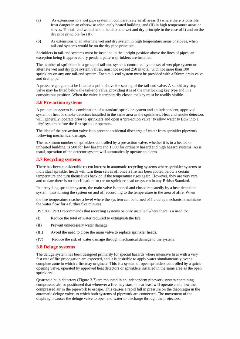
3.8 Deluge systems The deluge system has been designed primarily for special hazards where intensive fires with a very fast rate of fire propagation are expected, and it is desirable to apply water simultaneously over a complete zone in which a fire may originate. This is a system of open sprinklers controlled by a quick-opening valve, operated by approved heat detectors or sprinklers installed in the same area as the open sprinklers.
Quartzoid bulb detectors (Figure 3.7) are mounted in an independent pipework system containing compressed air, so positioned that wherever a fire may start, one at least will operate and allow the compressed air in the pipework to escape. This causes a rapid fall in pressure on the diaphragm in the automatic deluge valve, to which both systems of pipework are connected. The movement of the diaphragm causes the deluge valve to open and water to discharge through the projectors.
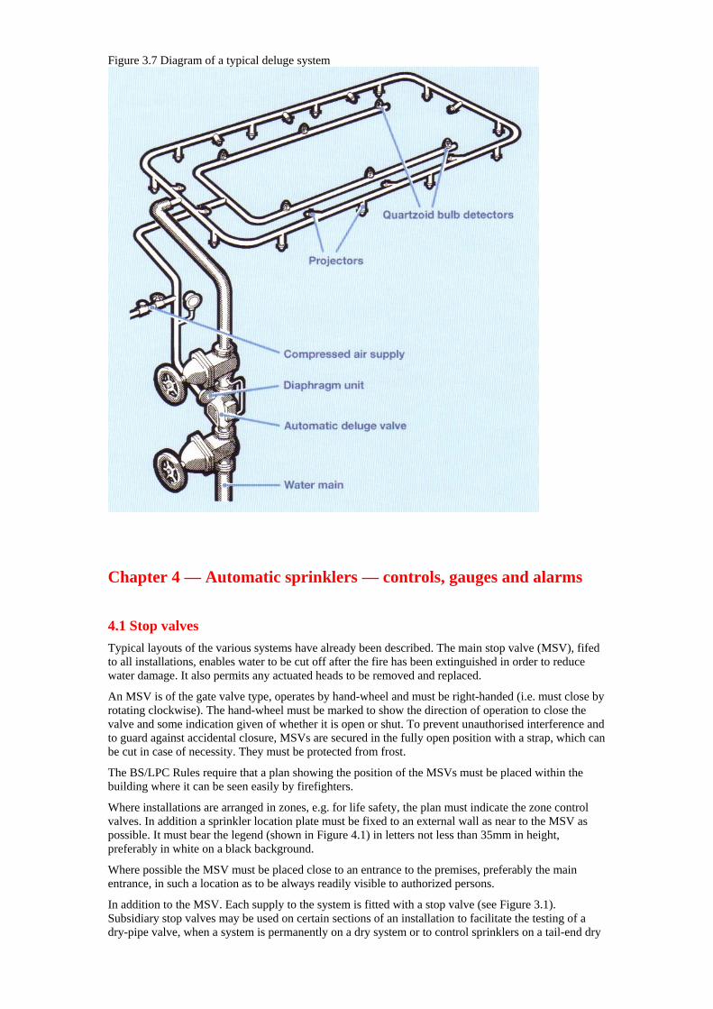
Figure 3.7 Diagram of a typical deluge system
Chapter 4 — Automatic sprinklers — controls, gauges and alarms
4.1 Stop valves Typical layouts of the various systems have already been described. The main stop valve (MSV), fifed to all installations, enables water to be cut off after the fire has been extinguished in order to reduce water damage. It also permits any actuated heads to be removed and replaced.
An MSV is of the gate valve type, operates by hand-wheel and must be right-handed (i.e. must close by rotating clockwise). The hand-wheel must be marked to show the direction of operation to close the valve and some indication given of whether it is open or shut. To prevent unauthorised interference and to guard against accidental closure, MSVs are secured in the fully open position with a strap, which can be cut in case of necessity. They must be protected from frost.
The BS/LPC Rules require that a plan showing the position of the MSVs must be placed within the building where it can be seen easily by firefighters.
Where installations are arranged in zones, e.g. for life safety, the plan must indicate the zone control valves. In addition a sprinkler location plate must be fixed to an external wall as near to the MSV as possible. It must bear the legend (shown in Figure 4.1) in letters not less than 35mm in height, preferably in white on a black background.
Where possible the MSV must be placed close to an entrance to the premises, preferably the main entrance, in such a location as to be always readily visible to authorized persons.
In addition to the MSV. Each supply to the system is fitted with a stop valve (see Figure 3.1). Subsidiary stop valves may be used on certain sections of an installation to facilitate the testing of a dry-pipe valve, when a system is permanently on a dry system or to control sprinklers on a tail-end dry
pipe system. The valves are of the interlocking key type and when the valves are closed the key is readily visible.
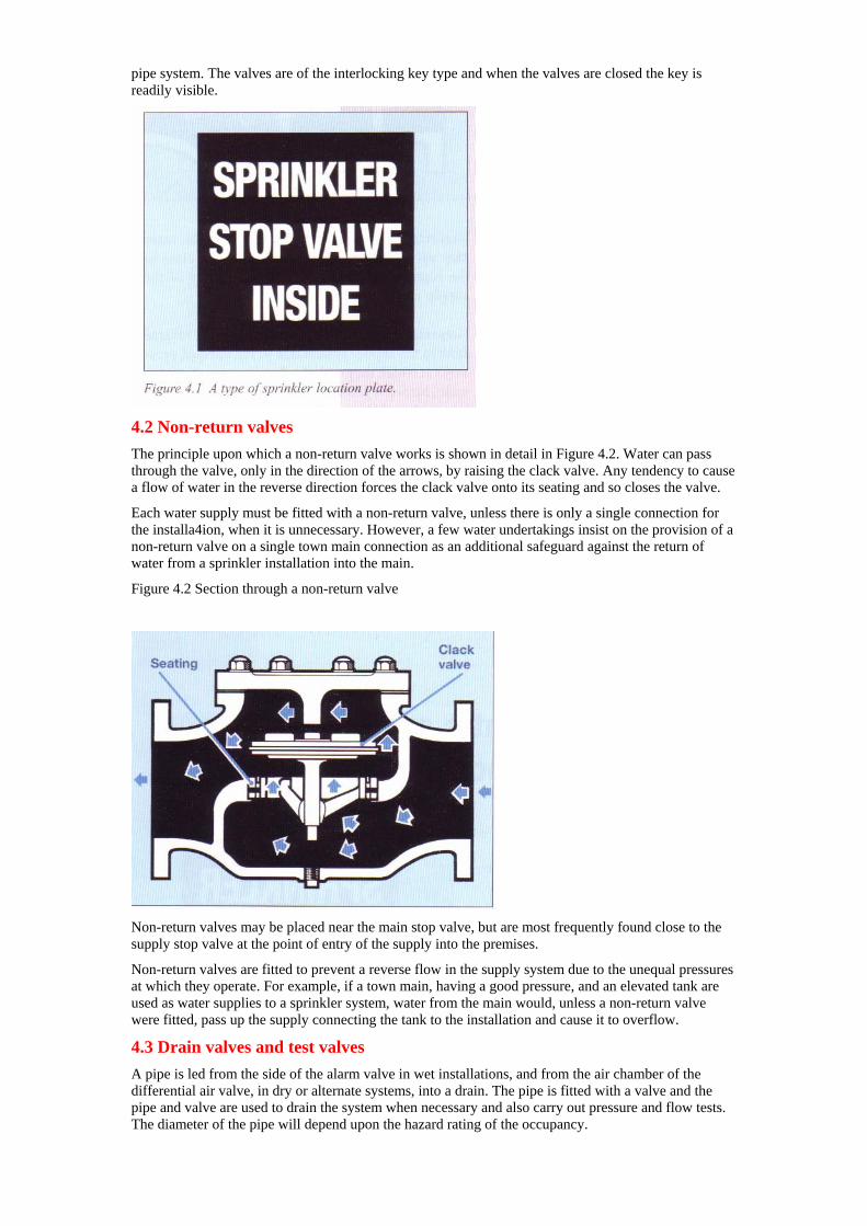
4.2 Non-return valves The principle upon which a non-return valve works is shown in detail in Figure 4.2. Water can pass through the valve, only in the direction of the arrows, by raising the clack valve. Any tendency to cause a flow of water in the reverse direction forces the clack valve onto its seating and so closes the valve.
Each water supply must be fitted with a non-return valve, unless there is only a single connection for the installa4ion, when it is unnecessary. However, a few water undertakings insist on the provision of a non-return valve on a single town main connection as an additional safeguard against the return of water from a sprinkler installation into the main.
Figure 4.2 Section through a non-return valve
Non-return valves may be placed near the main stop valve, but are most frequently found close to the supply stop valve at the point of entry of the supply into the premises.
Non-return valves are fitted to prevent a reverse flow in the supply system due to the unequal pressures at which they operate. For example, if a town main, having a good pressure, and an elevated tank are used as water supplies to a sprinkler system, water from the main would, unless a non-return valve were fitted, pass up the supply connecting the tank to the installation and cause it to overflow.
4.3 Drain valves and test valves A pipe is led from the side of the alarm valve in wet installations, and from the air chamber of the differential air valve, in dry or alternate systems, into a drain. The pipe is fitted with a valve and the pipe and valve are used to drain the system when necessary and also carry out pressure and flow tests. The diameter of the pipe will depend upon the hazard rating of the occupancy.
With systems supplied by town main elevated reservoirs and gravity tanks, facilities must be provided to enable ‘proving tests’ to be carried out at the valves of each installation. This is to verify that the water supply satisfies the requirements of pres sure and rates of flow specified for the particular hazard class (see Table 2.2). The proving tests must be carried out by the installing engineers at the time the system is installed and subsequently as required. The installation drain pipework
(Figure 4.3) is specifically designed to he used for the proving test.
4.4 Pipe drains In some installations part of the sprinkler piping is below the control valves and drain cocks are fitted at the lower parts of the piping so that they may be completely drained as necessary.
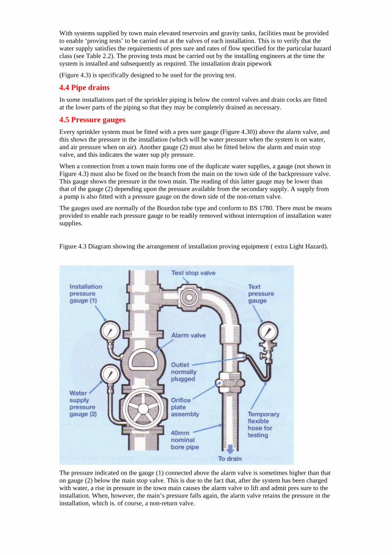
4.5 Pressure gauges Every sprinkler system must be fitted with a pres sure gauge (Figure 4.30)) above the alarm valve, and this shows the pressure in the installation (which will be water pressure when the system is on water, and air pressure when on air). Another gauge (2) must also be fitted below the alarm and main stop valve, and this indicates the water sup ply pressure.
When a connection from a town main forms one of the duplicate water supplies, a gauge (not shown in Figure 4.3) must also be fixed on the branch from the main on the town side of the backpressure valve. This gauge shows the pressure in the town main. The reading of this latter gauge may be lower than that of the gauge (2) depending upon the pressure available from the secondary supply. A supply from a pump is also fitted with a pressure gauge on the down side of the non-return valve.
The gauges used are normally of the Bourdon tube type and conform to BS 1780. There must be means provided to enable each pressure gauge to be readily removed without interruption of installation water supplies.
Figure 4.3 Diagram showing the arrangement of installation proving equipment ( extra Light Hazard).
The pressure indicated on the gauge (1) connected above the alarm valve is sometimes higher than that on gauge (2) below the main stop valve. This is due to the fact that, after the system has been charged with water, a rise in pressure in the town main causes the alarm valve to lift and admit pres sure to the installation. When, however, the main’s pressure falls again, the alarm valve retains the pressure in the installation, which is. of course, a non-return valve.
The difference in pressure sometimes results in a slight delay in the sounding of the alarm gong. When a sprinkler head opens, it is necessary for the pressure in the installation to fall below that in the main before the alarm valve opens and allows water to flow to the water turbine of the alarm.
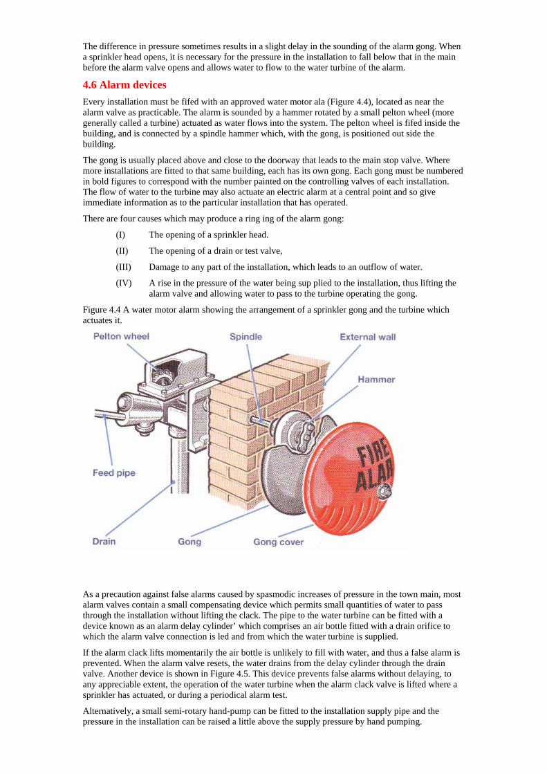
4.6 Alarm devices Every installation must be fifed with an approved water motor ala (Figure 4.4), located as near the alarm valve as practicable. The alarm is sounded by a hammer rotated by a small pelton wheel (more generally called a turbine) actuated as water flows into the system. The pelton wheel is fifed inside the building, and is connected by a spindle hammer which, with the gong, is positioned out side the building.
The gong is usually placed above and close to the doorway that leads to the main stop valve. Where more installations are fitted to that same building, each has its own gong. Each gong must be numbered in bold figures to correspond with the number painted on the controlling valves of each installation. The flow of water to the turbine may also actuate an electric alarm at a central point and so give immediate information as to the particular installation that has operated.
There are four causes which may produce a ring ing of the alarm gong:
(I) The opening of a sprinkler head.
(II) The opening of a drain or test valve,
(III) Damage to any part of the installation, which leads to an outflow of water.
(IV) A rise in the pressure of the water being sup plied to the installation, thus lifting the alarm valve and allowing water to pass to the turbine operating the gong.
Figure 4.4 A water motor alarm showing the arrangement of a sprinkler gong and the turbine which actuates it.
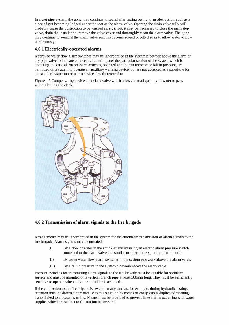
As a precaution against false alarms caused by spasmodic increases of pressure in the town main, most alarm valves contain a small compensating device which permits small quantities of water to pass through the installation without lifting the clack. The pipe to the water turbine can be fitted with a device known as an alarm delay cylinder’ which comprises an air bottle fitted with a drain orifice to which the alarm valve connection is led and from which the water turbine is supplied.
If the alarm clack lifts momentarily the air bottle is unlikely to fill with water, and thus a false alarm is prevented. When the alarm valve resets, the water drains from the delay cylinder through the drain valve. Another device is shown in Figure 4.5. This device prevents false alarms without delaying, to any appreciable extent, the operation of the water turbine when the alarm clack valve is lifted where a sprinkler has actuated, or during a periodical alarm test.
Alternatively, a small semi-rotary hand-pump can be fitted to the installation supply pipe and the pressure in the installation can be raised a little above the supply pressure by hand pumping.
In a wet pipe system, the gong may continue to sound after testing owing to an obstruction, such as a piece of grit becoming lodged under the seat of the alarm valve. Opening the drain valve fully will probably cause the obstruction to be washed away; if not, it may be necessary to close the main stop valve, drain the installation, remove the valve cover and thoroughly clean the alarm valve. The gong may continue to sound if the alarm valve seat has become scored or pitted so as to allow water to flow continuously.
4.6.1 Electrically-operated alarms Approved water flow alarm switches may be incorporated in the system pipework above the alarm or dry pipe valve to indicate on a central control panel the particular section of the system which is operating. Electric alarm pressure switches, operated at either an increase or fall in pressure, are permitted on a system to operate an auxiliary warning device, but are not accepted as a substitute for the standard water motor alarm device already referred to.
Figure 4.5 Compensating device on a clack valve which allows a small quantity of water to pass without hitting the clack.
4.6.2 Transmission of alarm signals to the fire brigade
Arrangements may be incorporated in the system for the automatic transmission of alarm signals to the fire brigade. Alarm signals may be initiated:
(I) By a flow of water in the sprinkler system using an electric alarm pressure switch connected to the alarm valve in a similar manner to the sprinkler alarm motor.
(II) By using water flow alarm switches in the system pipework above the alarm valve.
(III) By a fall in pressure in the system pipework above the alarm valve.
Pressure switches for transmitting alarm signals to the fire brigade must be suitable for sprinkler service and must be mounted on a vertical branch pipe at least 300mm long. They must be sufficiently sensitive to operate when only one sprinkler is actuated.
If the connection to the fire brigade is severed at any time as, for example, during hydraulic testing, attention must be drawn automatically to this situation by means of conspicuous duplicated warning lights linked to a buzzer warning. Means must be provided to prevent false alarms occurring with water supplies which are subject to fluctuation in pressure.
The system wiring and power supply must conform to the requirements laid down in BS 5839:
Part I, including a test of:
(I) The fire brigade or Alarm Receiving Centres (ARC) connections.
(II) The circuit between the alarm switch and the
control unit.
(III) The batteries.
Tests must be made every weekday (except holidays). The first two tests need only be made once a week provided the circuits used are continuously monitored. A notice must be fixed close to the sprinkler test valves of each installation to indicate a direct alarm connection to the fire brigade.
On sprinkler systems where arrangements are incorporated for the automatic transmission of alarm signals to the fire brigade, the arrangements will be regarded as approved by the BS/LPC if they comply with certain conditions, as follows:
(I) There must be either a connection directly or through a ARC, approved by the BS/LPC and from there to a local authority fire station staffed by whole-time personnel, or part-time retained personnel alerted by call- out systems; Or
(II) A direct connection to a permanently staffed watch room of a private fire brigade.
The direct line from the premises whether to the fire brigade control, approved ARC or private fire brigade must terminate in a watch room or control room permanently staffed day and night.
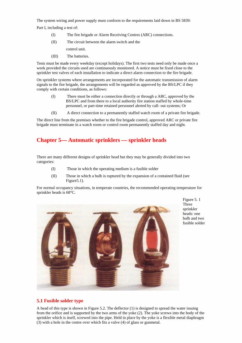
Chapter 5— Automatic sprinklers — sprinkler heads There are many different designs of sprinkler head but they may be generally divided into two categories:
(I) Those in which the operating medium is a fusible solder
(II) Those in which a bulb is ruptured by the expansion of a contained fluid (see Figure5.1).
For normal occupancy situations, in temperate countries, the recommended operating temperature for sprinkler heads is 68°C.
Figure 5. 1 Three sprinkler heads: one bulb and two fusible solder
5.1 Fusible solder type A head of this type is shown in Figure 5.2. The deflector (1) is designed to spread the water issuing from the orifice and is supported by the two arms of the yoke (2). The yoke screws into the body of the sprinkler which is itself, screwed into the pipe. Held in place by the yoke is a flexible metal diaphragm (3) with a hole in the centre over which fits a valve (4) of glass or gunmetal.
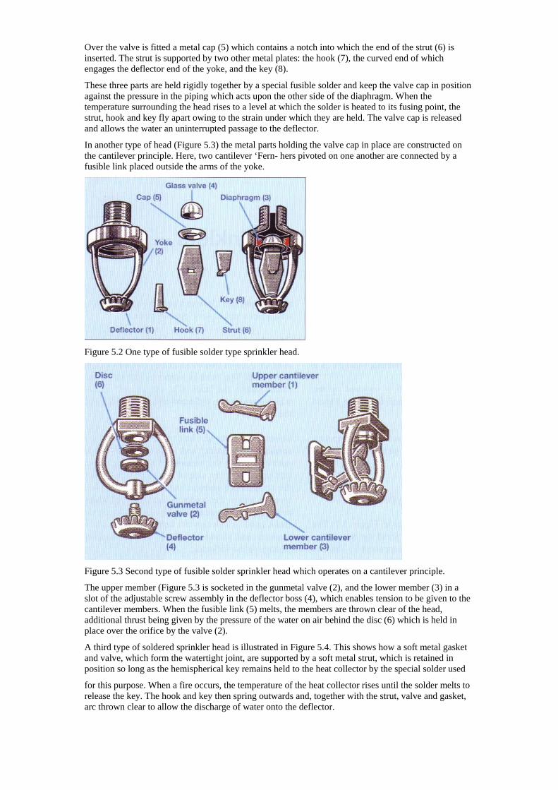
Over the valve is fitted a metal cap (5) which contains a notch into which the end of the strut (6) is inserted. The strut is supported by two other metal plates: the hook (7), the curved end of which
sition ther side of the diaphragm. When the
on one another are connected by a
engages the deflector end of the yoke, and the key (8).
These three parts are held rigidly together by a special fusible solder and keep the valve cap in poagainst the pressure in the piping which acts upon the otemperature surrounding the head rises to a level at which the solder is heated to its fusing point, the strut, hook and key fly apart owing to the strain under which they are held. The valve cap is released and allows the water an uninterrupted passage to the deflector.
In another type of head (Figure 5.3) the metal parts holding the valve cap in place are constructed on the cantilever principle. Here, two cantilever ‘Fern- hers pivotedfusible link placed outside the arms of the yoke.
Figure 5.2 One type of fusible solder type sprinkler head.
Figure 5.3 Second type of fusible solder sprinkler head which operates on a cantilever principle.
The upper member (Figure 5.3 is socketed in the gunmetal valve (2), and the lower member (3) in a to the
int, are supported by a soft metal strut, which is retained in
to
slot of the adjustable screw assembly in the deflector boss (4), which enables tension to be given cantilever members. When the fusible link (5) melts, the members are thrown clear of the head, additional thrust being given by the pressure of the water on air behind the disc (6) which is held in place over the orifice by the valve (2).
A third type of soldered sprinkler head is illustrated in Figure 5.4. This shows how a soft metal gasket and valve, which form the watertight joposition so long as the hemispherical key remains held to the heat collector by the special solder used
for this purpose. When a fire occurs, the temperature of the heat collector rises until the solder meltsrelease the key. The hook and key then spring outwards and, together with the strut, valve and gasket, arc thrown clear to allow the discharge of water onto the deflector.
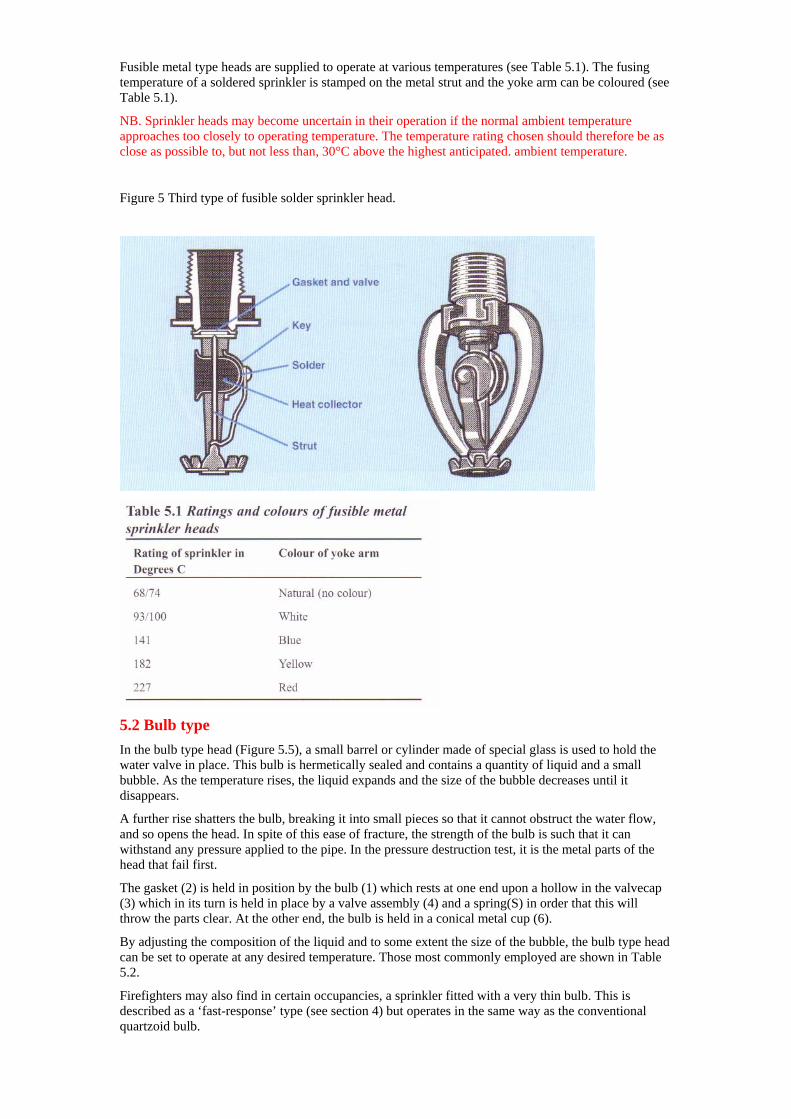
Fusible metal type heads are supplied to operate at various temperatures (see Table 5.1). The fusing temperature of a soldered sprinkler is stamped on the metal strut and the yoke arm can be coloured (see Table 5.1).
NB. Sprinkler heads may become uncertain in their operation if the normal ambient temperature approaches too closely to operating temperature. The temperature rating chosen should therefore be as close as possible to, but not less than, 30°C above the highest anticipated. ambient temperature.
Figure 5 Third type of fusible solder sprinkler head.
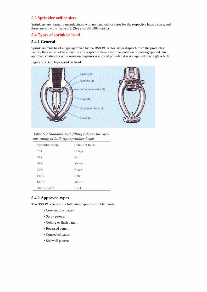
5.2 Bulb type In the bulb type head (Figure 5.5), a small barrel or cylinder made of special glass is used to hold the water valve in place. This bulb is hermetically sealed and contains a quantity of liquid and a small bubble. As the temperature rises, the liquid expands and the size of the bubble decreases until it disappears.
A further rise shatters the bulb, breaking it into small pieces so that it cannot obstruct the water flow, and so opens the head. In spite of this ease of fracture, the strength of the bulb is such that it can withstand any pressure applied to the pipe. In the pressure destruction test, it is the metal parts of the head that fail first.
The gasket (2) is held in position by the bulb (1) which rests at one end upon a hollow in the valvecap (3) which in its turn is held in place by a valve assembly (4) and a spring(S) in order that this will throw the parts clear. At the other end, the bulb is held in a conical metal cup (6).
By adjusting the composition of the liquid and to some extent the size of the bubble, the bulb type head can be set to operate at any desired temperature. Those most commonly employed are shown in Table 5.2.
Firefighters may also find in certain occupancies, a sprinkler fitted with a very thin bulb. This is described as a ‘fast-response’ type (see section 4) but operates in the same way as the conventional quartzoid bulb.
5.3 Sprinkler orifice sizes Sprinklers are normally manufactured with nominal orifice sizes for the respective hazard class, and these are shown in Table 5.3. (See also BS 5306 Part 2)
5.4 Types of sprinkler head
5.4.1 General Sprinklers must be of a type approved by the BS/LPC Rules. After dispatch from the production factory they must not be altered in any respect or have any ornamentation or coating applied. An approved coating for anti-corrosion purposes is allowed provided it is not applied to any glass bulb.
Figure 5.5 Bulb type sprinkler head.
5.4.2 Approved types The BS/LPC specific the following types of sprinkler heads:
• Conventional pattern
• Spray pattern
• Ceiling or flush pattern
• Recessed pattern
• Concealed pattern
• Sidewall pattern
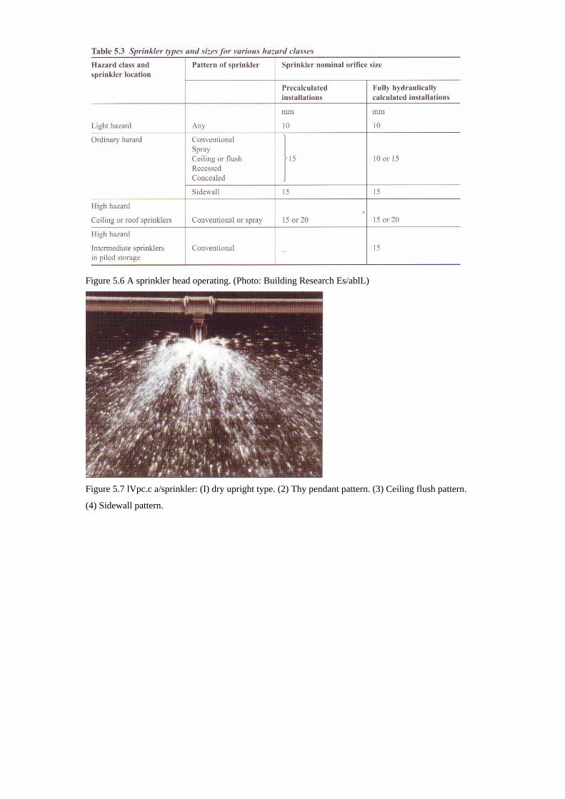
Figure 5.6 A sprinkler head operating. (Photo: Building Research Es/ablL)
Figure 5.7 lVpc.c a/sprinkler: (I) dry upright type. (2) Thy pendant pattern. (3) Ceiling flush pattern.
(4) Sidewall pattern.
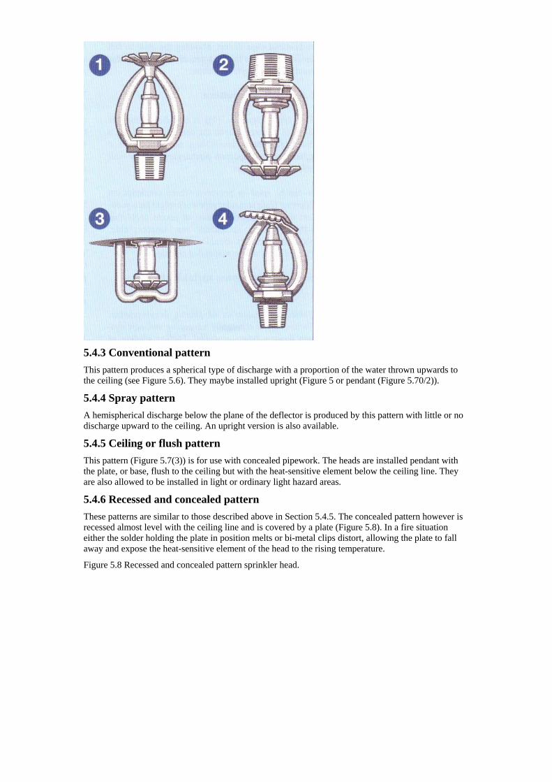
5.4.3 Conventional pattern This pattern produces a spherical type of discharge with a proportion of the water thrown upwards to the ceiling (see Figure 5.6). They maybe installed upright (Figure 5 or pendant (Figure 5.70/2)).
5.4.4 Spray pattern A hemispherical discharge below the plane of the deflector is produced by this pattern with little or no discharge upward to the ceiling. An upright version is also available.
5.4.5 Ceiling or flush pattern This pattern (Figure 5.7(3)) is for use with concealed pipework. The heads are installed pendant with the plate, or base, flush to the ceiling but with the heat-sensitive element below the ceiling line. They are also allowed to be installed in light or ordinary light hazard areas.
5.4.6 Recessed and concealed pattern These patterns are similar to those described above in Section 5.4.5. The concealed pattern however is recessed almost level with the ceiling line and is covered by a plate (Figure 5.8). In a fire situation either the solder holding the plate in position melts or bi-metal clips distort, allowing the plate to fall away and expose the heat-sensitive element of the head to the rising temperature.
Figure 5.8 Recessed and concealed pattern sprinkler head.
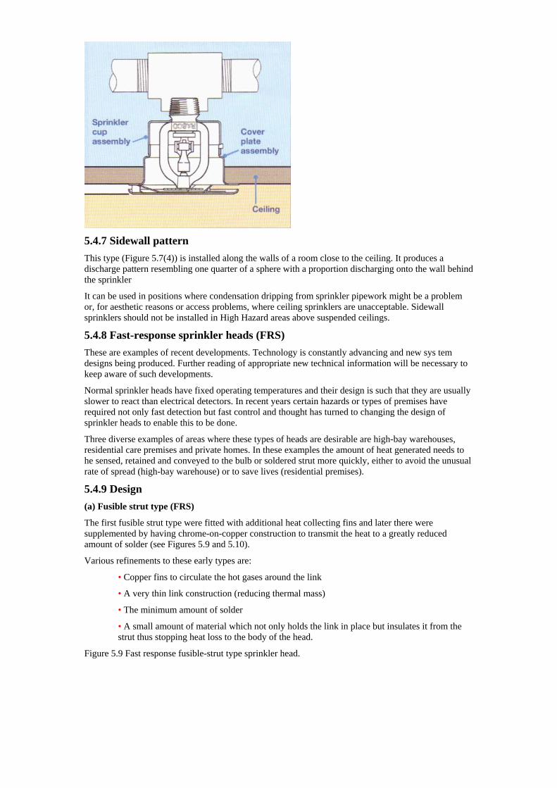
5.4.7 Sidewall pattern This type (Figure 5.7(4)) is installed along the walls of a room close to the ceiling. It produces a discharge pattern resembling one quarter of a sphere with a proportion discharging onto the wall behind the sprinkler
It can be used in positions where condensation dripping from sprinkler pipework might be a problem or, for aesthetic reasons or access problems, where ceiling sprinklers are unacceptable. Sidewall sprinklers should not be installed in High Hazard areas above suspended ceilings.
5.4.8 Fast-response sprinkler heads (FRS) These are examples of recent developments. Technology is constantly advancing and new sys tem designs being produced. Further reading of appropriate new technical information will be necessary to keep aware of such developments.
Normal sprinkler heads have fixed operating temperatures and their design is such that they are usually slower to react than electrical detectors. In recent years certain hazards or types of premises have required not only fast detection but fast control and thought has turned to changing the design of sprinkler heads to enable this to be done.
Three diverse examples of areas where these types of heads are desirable are high-bay warehouses, residential care premises and private homes. In these examples the amount of heat generated needs to he sensed, retained and conveyed to the bulb or soldered strut more quickly, either to avoid the unusual rate of spread (high-bay warehouse) or to save lives (residential premises).
5.4.9 Design (a) Fusible strut type (FRS)
The first fusible strut type were fitted with additional heat collecting fins and later there were supplemented by having chrome-on-copper construction to transmit the heat to a greatly reduced amount of solder (see Figures 5.9 and 5.10).
Various refinements to these early types are:
• Copper fins to circulate the hot gases around the link
• A very thin link construction (reducing thermal mass)
• The minimum amount of solder
• A small amount of material which not only holds the link in place but insulates it from the strut thus stopping heat loss to the body of the head.
Figure 5.9 Fast response fusible-strut type sprinkler head.
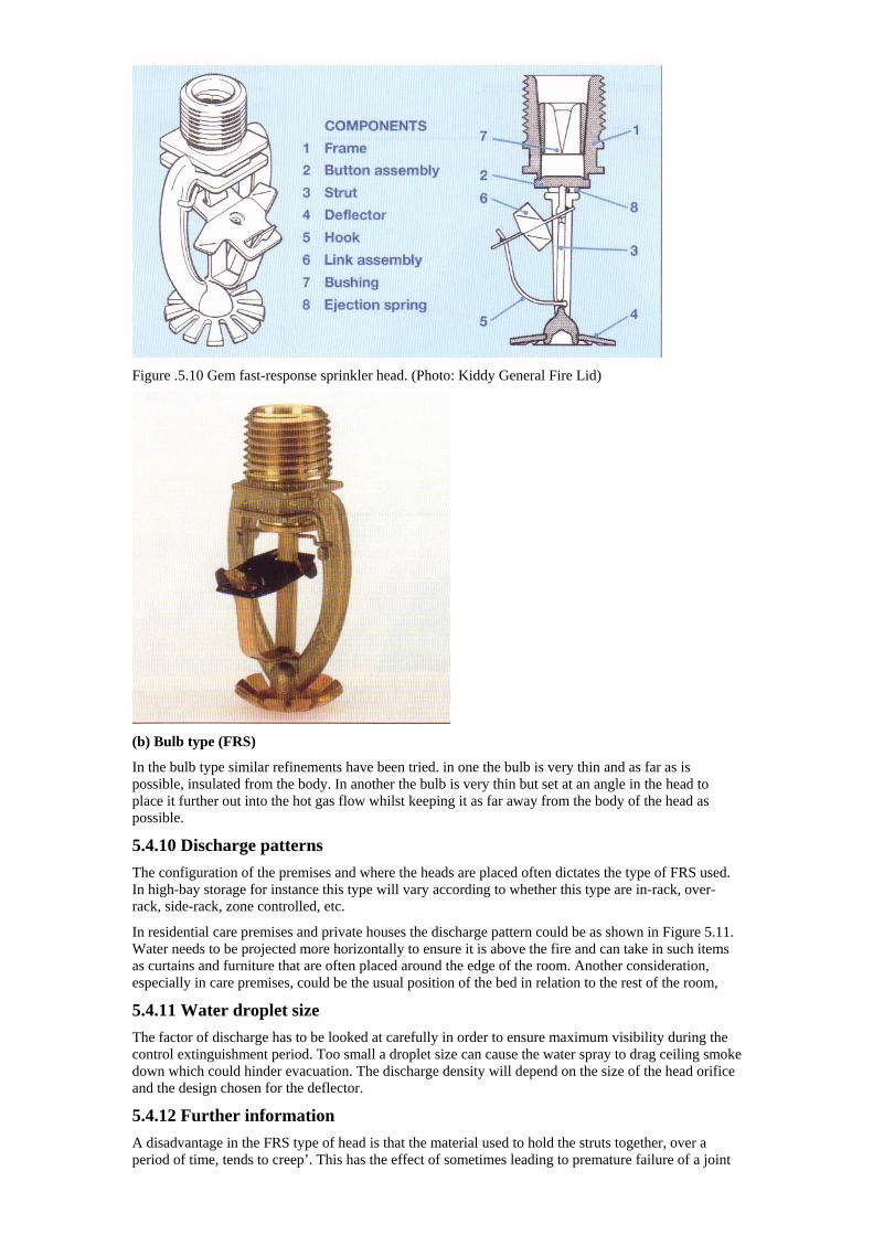
Figure .5.10 Gem fast-response sprinkler head. (Photo: Kiddy General Fire Lid)
(b) Bulb type (FRS)
In the bulb type similar refinements have been tried. in one the bulb is very thin and as far as is possible, insulated from the body. In another the bulb is very thin but set at an angle in the head to place it further out into the hot gas flow whilst keeping it as far away from the body of the head as possible.
5.4.10 Discharge patterns The configuration of the premises and where the heads are placed often dictates the type of FRS used. In high-bay storage for instance this type will vary according to whether this type are in-rack, over-rack, side-rack, zone controlled, etc.
In residential care premises and private houses the discharge pattern could be as shown in Figure 5.11. Water needs to be projected more horizontally to ensure it is above the fire and can take in such items as curtains and furniture that are often placed around the edge of the room. Another consideration, especially in care premises, could be the usual position of the bed in relation to the rest of the room,
5.4.11 Water droplet size The factor of discharge has to be looked at carefully in order to ensure maximum visibility during the control extinguishment period. Too small a droplet size can cause the water spray to drag ceiling smoke down which could hinder evacuation. The discharge density will depend on the size of the head orifice and the design chosen for the deflector.
5.4.12 Further information A disadvantage in the FRS type of head is that the material used to hold the struts together, over a period of time, tends to creep’. This has the effect of sometimes leading to premature failure of a joint
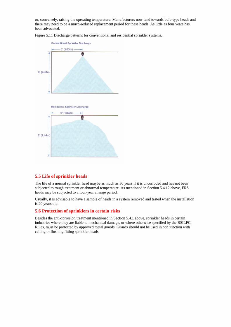
or, conversely, raising the operating temperature. Manufacturers now tend towards bulb-type heads and there may need to be a much-reduced replacement period for these heads. As little as four years has been advocated.
Figure 5.11 Discharge patterns for conventional and residential sprinkler systems.
5.5 Life of sprinkler heads The life of a normal sprinkler head maybe as much as 50 years if it is uncorroded and has not been subjected to rough treatment or abnormal temperature. As mentioned in Section 5.4.12 above, FRS heads may be subjected to a four-year change period.
Usually, it is advisable to have a sample of heads in a system removed and tested when the installation is 20 years old.
5.6 Protection of sprinklers in certain risks Besides the anti-corrosion treatment mentioned in Section 5.4.1 above, sprinkler heads in certain industries where they are liable to mechanical damage, or where otherwise specified by the BSILPC Rules, must be protected by approved metal guards. Guards should not be used in con junction with ceiling or flushing fitting sprinkler heads.
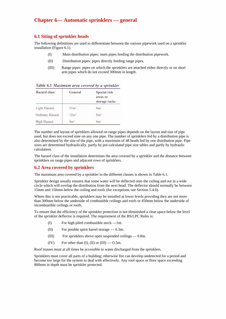
Chapter 6— Automatic sprinklers — general
6.1 Siting of sprinkler heads The following definitions are used to differentiate between the various pipework used on a sprinkler installation (Figure 6.1).
(I) Main distribution pipes: main pipes feeding the distribution pipework.
(II) Distribution pipes: pipes directly feeding range pipes.
(III) Range pipes: pipes on which the sprinklers are attached either directly or on short arm pipes which do not exceed 300mm in length.
The number and layout of sprinklers allowed on range pipes depends on the layout and size of pipe used, but does not exceed nine on any one pipe. The number of sprinklers fed by a distribution pipe is also determined by the size of the pipe, with a maximum of 48 heads fed by one distribution pipe. Pipe sizes are determined hydraulically, partly by pre-calculated pipe size tables and partly by hydraulic calculation.
The hazard class of the installation determines the area covered by a sprinkler and the distance between sprinklers on range pipes and adjacent rows of sprinklers.
6.2 Area covered by sprinklers The maximum area covered by a sprinkler in the different classes is shown in Table 6.1.
Sprinkler design usually ensures that some water will be deflected onto the ceiling and out in a wide circle which will overlap the distribution from the next head. The deflector should normally be between 15mm and 150mm below the ceiling and roofs (for exceptions, see Section 5.4.6).
Where this is not practicable, sprinklers may be installed at lower levels providing they are not more than 300mm below the underside of combustible ceilings and roofs or 450mm below the underside of incombustible ceilings or roofs.
To ensure that the efficiency of the sprinkler protection is not diminished a clear space below the level of the sprinkler deflector is required. The requirement of the BS/LPC Rules is:
(I) For high piled combustible stock —1m.
(II) For potable spirit barrel storage — 0.3m.
(III) For sprinklers above open suspended ceilings — 0.8m.
(IV) For other than (I), (II) or (III) — O.5m.
Roof trusses must at all times be accessible to water discharged from the sprinklers.
Sprinklers must cover all parts of a building; otherwise fire can develop undetected for a period and become too large for the system to deal with effectively. Any roof space or floor space exceeding 800mm in depth must be sprinkler protected.
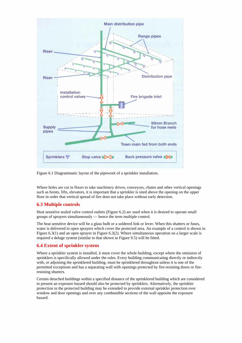
Figure 6.1 Diagrammatic layout of the pipework of a sprinkler installation.
Where holes are cut in floors to take machinery drives, conveyors, chutes and other vertical openings such as hoists, lifts, elevators, it is important that a sprinkler is sited above the opening on the upper floor in order that vertical spread of fire does not take place without early detection.
6.3 Multiple controls Heat sensitive sealed valve control outlets (Figure 6.2) arc used when it is desired to operate small groups of sprayers simultaneously — hence the term multiple control.
The heat sensitive device will be a glass bulb or a soldered link or lever. When this shatters or fuses, water is delivered to open sprayers which cover the protected area. An example of a control is shown in Figure 6.3(1) and an open sprayer in Figure 6.3(2). Where simultaneous operation on a larger scale is required a deluge system (similar to that shown in Figure 9.5) will he fitted.
6.4 Extent of sprinkler system Where a sprinkler system is installed, it must cover the whole building, except where the omission of sprinklers is specifically allowed under the rules. Every building communicating directly or indirectly with, or adjoining the sprinklered building. must be sprinklered throughout unless it is one of the permitted exceptions and has a separating wall with openings protected by fire-resisting doors or fire-resisting shutters.
Certain detached buildings within a specified distance of the sprinklered building which are considered to present an exposure hazard should also be protected by sprinklers. Alternatively, the sprinkler protection in the protected building may be extended to provide external sprinkler protection over window and door openings and over any combustible sections of the wall opposite the exposure hazard.
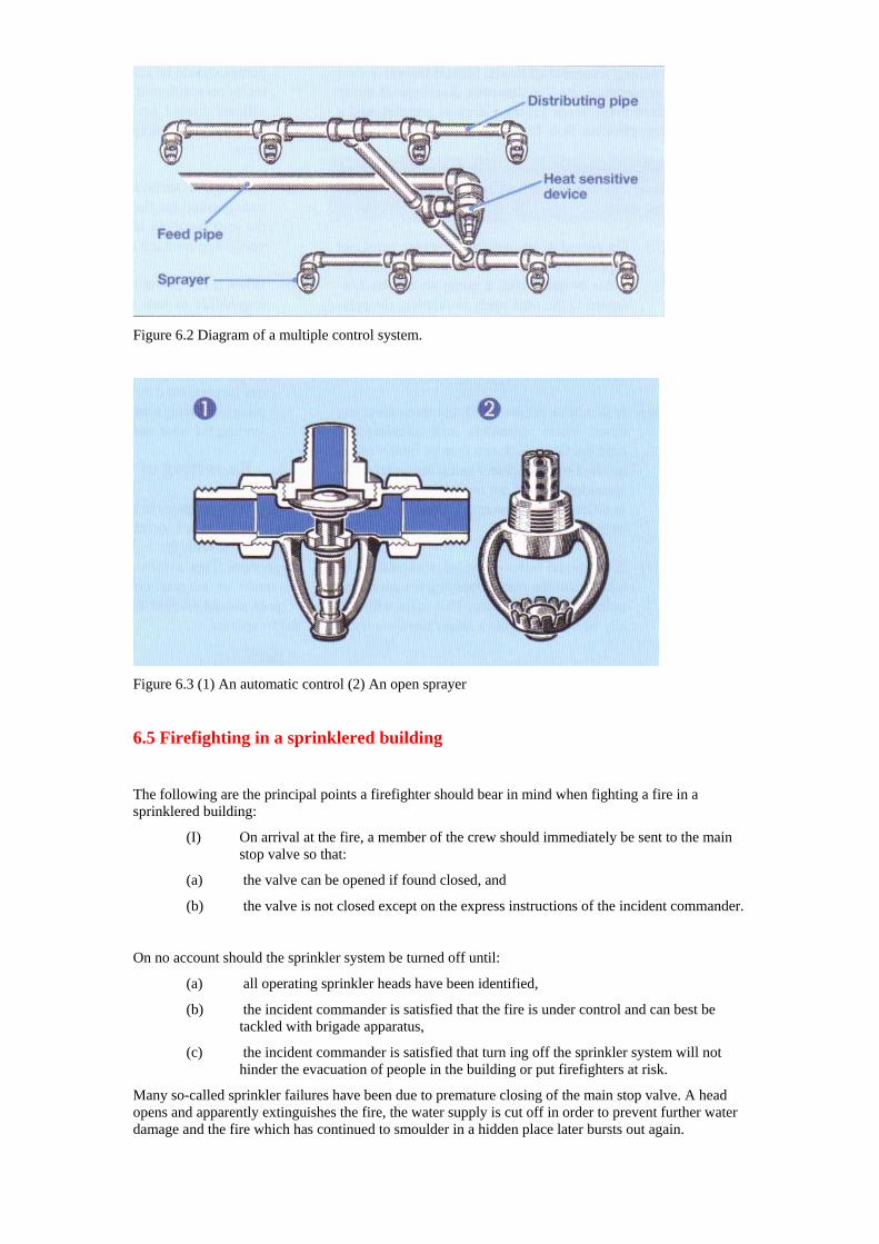
Figure 6.2 Diagram of a multiple control system.
Figure 6.3 (1) An automatic control (2) An open sprayer
6.5 Firefighting in a sprinklered building
The following are the principal points a firefighter should bear in mind when fighting a fire in a sprinklered building:
(I) On arrival at the fire, a member of the crew should immediately be sent to the main stop valve so that:
(a) the valve can be opened if found closed, and
(b) the valve is not closed except on the express instructions of the incident commander.
On no account should the sprinkler system be turned off until:
(a) all operating sprinkler heads have been identified,
(b) the incident commander is satisfied that the fire is under control and can best be tackled with brigade apparatus,
(c) the incident commander is satisfied that turn ing off the sprinkler system will not hinder the evacuation of people in the building or put firefighters at risk.
Many so-called sprinkler failures have been due to premature closing of the main stop valve. A head opens and apparently extinguishes the fire, the water supply is cut off in order to prevent further water damage and the fire which has continued to smoulder in a hidden place later bursts out again.
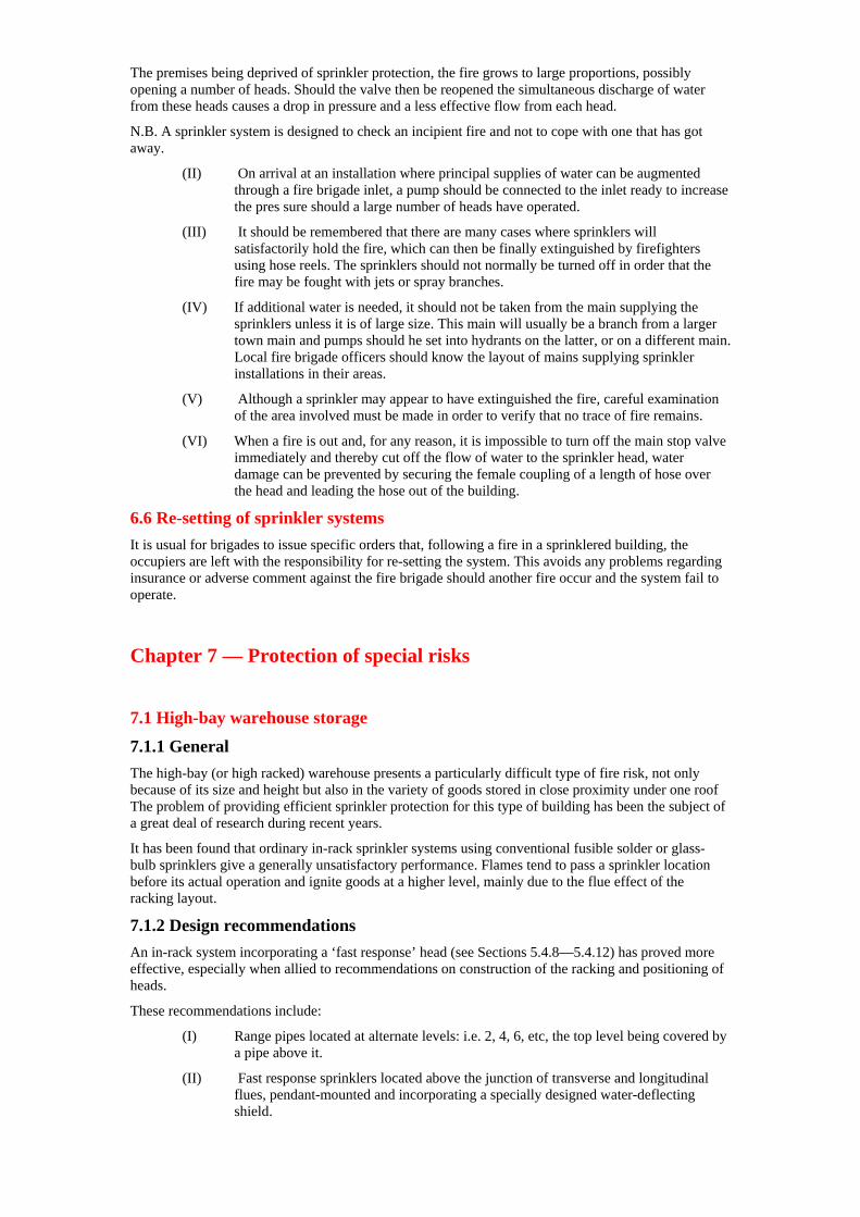
The premises being deprived of sprinkler protection, the fire grows to large proportions, possibly opening a number of heads. Should the valve then be reopened the simultaneous discharge of water from these heads causes a drop in pressure and a less effective flow from each head.
N.B. A sprinkler system is designed to check an incipient fire and not to cope with one that has got away.
(II) On arrival at an installation where principal supplies of water can be augmented through a fire brigade inlet, a pump should be connected to the inlet ready to increase the pres sure should a large number of heads have operated.
(III) It should be remembered that there are many cases where sprinklers will satisfactorily hold the fire, which can then be finally extinguished by firefighters using hose reels. The sprinklers should not normally be turned off in order that the fire may be fought with jets or spray branches.
(IV) If additional water is needed, it should not be taken from the main supplying the sprinklers unless it is of large size. This main will usually be a branch from a larger town main and pumps should he set into hydrants on the latter, or on a different main. Local fire brigade officers should know the layout of mains supplying sprinkler installations in their areas.
(V) Although a sprinkler may appear to have extinguished the fire, careful examination of the area involved must be made in order to verify that no trace of fire remains.
(VI) When a fire is out and, for any reason, it is impossible to turn off the main stop valve immediately and thereby cut off the flow of water to the sprinkler head, water damage can be prevented by securing the female coupling of a length of hose over the head and leading the hose out of the building.
6.6 Re-setting of sprinkler systems It is usual for brigades to issue specific orders that, following a fire in a sprinklered building, the occupiers are left with the responsibility for re-setting the system. This avoids any problems regarding insurance or adverse comment against the fire brigade should another fire occur and the system fail to operate.
Chapter 7 — Protection of special risks 7.1 High-bay warehouse storage
7.1.1 General The high-bay (or high racked) warehouse presents a particularly difficult type of fire risk, not only because of its size and height but also in the variety of goods stored in close proximity under one roof The problem of providing efficient sprinkler protection for this type of building has been the subject of a great deal of research during recent years.
It has been found that ordinary in-rack sprinkler systems using conventional fusible solder or glass- bulb sprinklers give a generally unsatisfactory performance. Flames tend to pass a sprinkler location before its actual operation and ignite goods at a higher level, mainly due to the flue effect of the racking layout.
7.1.2 Design recommendations An in-rack system incorporating a ‘fast response’ head (see Sections 5.4.8—5.4.12) has proved more effective, especially when allied to recommendations on construction of the racking and positioning of heads.
These recommendations include:
(I) Range pipes located at alternate levels: i.e. 2, 4, 6, etc, the top level being covered by a pipe above it.
(II) Fast response sprinklers located above the junction of transverse and longitudinal flues, pendant-mounted and incorporating a specially designed water-deflecting shield.
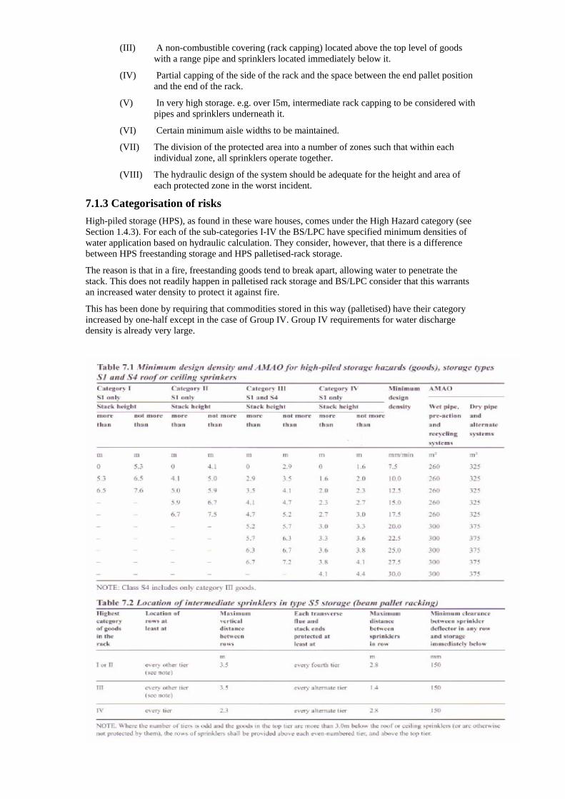
(III) A non-combustible covering (rack capping) located above the top level of goods with a range pipe and sprinklers located immediately below it.
(IV) Partial capping of the side of the rack and the space between the end pallet position and the end of the rack.
(V) In very high storage. e.g. over I5m, intermediate rack capping to be considered with pipes and sprinklers underneath it.
(VI) Certain minimum aisle widths to be maintained.
(VII) The division of the protected area into a number of zones such that within each individual zone, all sprinklers operate together.
(VIII) The hydraulic design of the system should be adequate for the height and area of each protected zone in the worst incident.
7.1.3 Categorisation of risks High-piled storage (HPS), as found in these ware houses, comes under the High Hazard category (see Section 1.4.3). For each of the sub-categories I-IV the BS/LPC have specified minimum densities of water application based on hydraulic calculation. They consider, however, that there is a difference between HPS freestanding storage and HPS palletised-rack storage.
The reason is that in a fire, freestanding goods tend to break apart, allowing water to penetrate the stack. This does not readily happen in palletised rack storage and BS/LPC consider that this warrants an increased water density to protect it against fire.
This has been done by requiring that commodities stored in this way (palletised) have their category increased by one-half except in the case of Group IV. Group IV requirements for water discharge density is already very large.
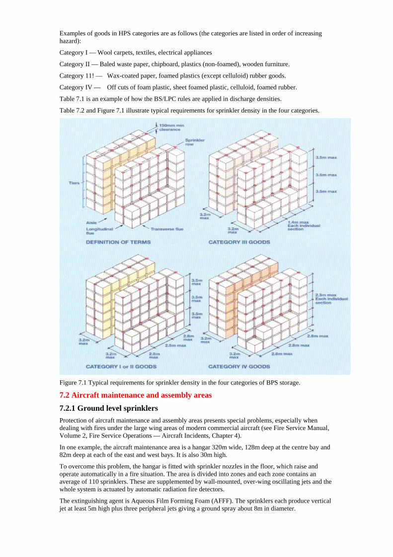
Examples of goods in HPS categories are as follows (the categories are listed in order of increasing hazard):
Category I — Wool carpets, textiles, electrical appliances
Category II — Baled waste paper, chipboard, plastics (non-foamed), wooden furniture.
Category 11! — Wax-coated paper, foamed plastics (except celluloid) rubber goods.
Category IV — Off cuts of foam plastic, sheet foamed plastic, celluloid, foamed rubber.
Table 7.1 is an example of how the BS/LPC rules are applied in discharge densities.
Table 7.2 and Figure 7.1 illustrate typical requirements for sprinkler density in the four categories.
Figure 7.1 Typical requirements for sprinkler density in the four categories of BPS storage.
7.2 Aircraft maintenance and assembly areas
7.2.1 Ground level sprinklers Protection of aircraft maintenance and assembly areas presents special problems, especially when dealing with fires under the large wing areas of modern commercial aircraft (see Fire Service Manual, Volume 2, Fire Service Operations — Aircraft Incidents, Chapter 4).
In one example, the aircraft maintenance area is a hangar 320m wide, 128m deep at the centre bay and 82m deep at each of the east and west bays. It is also 30m high.
To overcome this problem, the hangar is fitted with sprinkler nozzles in the floor, which raise and operate automatically in a fire situation. The area is divided into zones and each zone contains an average of 110 sprinklers. These are supplemented by wall-mounted, over-wing oscillating jets and the whole system is actuated by automatic radiation fire detectors.
The extinguishing agent is Aqueous Film Forming Foam (AFFF). The sprinklers each produce vertical jet at least 5m high plus three peripheral jets giving a ground spray about 8m in diameter.
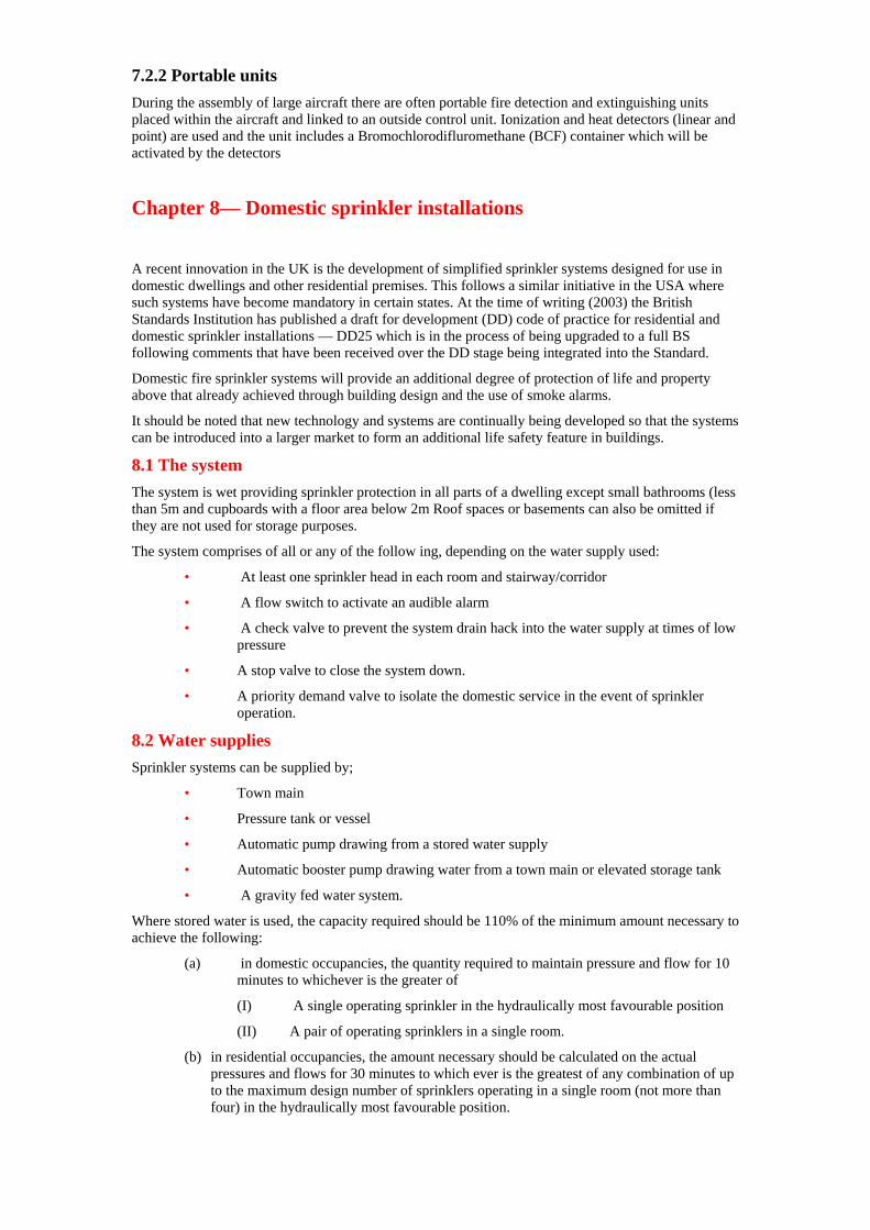
7.2.2 Portable units During the assembly of large aircraft there are often portable fire detection and extinguishing units placed within the aircraft and linked to an outside control unit. Ionization and heat detectors (linear and point) are used and the unit includes a Bromochlorodifluromethane (BCF) container which will be activated by the detectors
Chapter 8— Domestic sprinkler installations A recent innovation in the UK is the development of simplified sprinkler systems designed for use in domestic dwellings and other residential premises. This follows a similar initiative in the USA where such systems have become mandatory in certain states. At the time of writing (2003) the British Standards Institution has published a draft for development (DD) code of practice for residential and domestic sprinkler installations — DD25 which is in the process of being upgraded to a full BS following comments that have been received over the DD stage being integrated into the Standard.
Domestic fire sprinkler systems will provide an additional degree of protection of life and property above that already achieved through building design and the use of smoke alarms.
It should be noted that new technology and systems are continually being developed so that the systems can be introduced into a larger market to form an additional life safety feature in buildings.
8.1 The system The system is wet providing sprinkler protection in all parts of a dwelling except small bathrooms (less than 5m and cupboards with a floor area below 2m Roof spaces or basements can also be omitted if they are not used for storage purposes.
The system comprises of all or any of the follow ing, depending on the water supply used:
• At least one sprinkler head in each room and stairway/corridor
• A flow switch to activate an audible alarm
• A check valve to prevent the system drain hack into the water supply at times of low pressure
• A stop valve to close the system down.
• A priority demand valve to isolate the domestic service in the event of sprinkler operation.
8.2 Water supplies Sprinkler systems can be supplied by;
• Town main
• Pressure tank or vessel
• Automatic pump drawing from a stored water supply
• Automatic booster pump drawing water from a town main or elevated storage tank
• A gravity fed water system.
Where stored water is used, the capacity required should be 110% of the minimum amount necessary to achieve the following:
(a) in domestic occupancies, the quantity required to maintain pressure and flow for 10 minutes to whichever is the greater of
(I) A single operating sprinkler in the hydraulically most favourable position
(II) A pair of operating sprinklers in a single room.
(b) in residential occupancies, the amount necessary should be calculated on the actual pressures and flows for 30 minutes to which ever is the greatest of any combination of up to the maximum design number of sprinklers operating in a single room (not more than four) in the hydraulically most favourable position.
8.3 Sprinkler heads The system uses either conventional spray or side wall sprinkler heads or residential and domestic pattern heads, which give an outward and down ward discharge of water. In both cases, the water flow rate should not be less than:
(I) For domestic occupancies:
(a) 60 11mm through any single sprinkler;
(b) 42 1 through each of two sprinklers operating simultaneously in a single room.
(II) For residential occupancies:
(a) 60 1 through any single sprinkler
(b) 42 1 for each sprinkler operating simultaneously up to a maximum of four sprinklers in a single room.
8.4 Sprinkler spacing and coverage The maximum area covered by each sprinkler should either be in accordance with the manufacturer’s specification or 15m whichever is the lesser. Sprinklers should not he more than 4m apart or more than 2in from any wall or partition. The distance between sprinklers in a room should not be less than 2m.
Sprinklers should be positioned so that:
(I) Pendant upright conventional or residential and domestic sprinklers have their heat sensitive elements not more than 100mm below the ceiling (100—150mm in the case of side wall sprinklers).
(II) The whole of the floor and the walls up to 0.7m below the ceiling should be wetted by an operating sprinkler.
(III) No sprinkler is within 50mm of a wall or partition.
(IV) Sprinklers may be either strutted or glass bulb and should be colour coded. The temperature rating for sprinklers should be:
(a) the closest but at least 30°C greater than the highest anticipated ambient temperature of the location;
(b) Within the range of 79°C—100°C when installed under glass roofs.
(V) The potential for a shielded fire should be taken into account.
8.5 Alarms The discharge through any one-sprinkler head should cause the alarm valve to trigger an alarm in the protected property. The alarm should be audible throughout the property.
An additional alarm should be positioned outside of the protected property and give both an audible and visual signal. The alarm should be clearly labelled ‘Fire Alarm’.
Chapter 9 —Other installations using water 9.1 Drenchers While a sprinkler system protects a building from internal fire, drenchers are placed on roofs and over windows and external openings to protect the building from damage by exposure to a fire in adjacent premises. The layout of a typical drencher system is shown in Figure 9.1
A drencher system is comprised of water heads somewhat similar to those of sprinklers; these may be sealed or unsealed (open drenchers), but in the latter case the water is turned on manually. In a few instances drenchers may be controlled by quick- opening valves operated by loss of air pressure in a detector line system in a similar manner to high velocity water spray systems (see Section 9.2).
Figure 9.1 Diagram showing a typical drencher system.
Drenchers are of three main types:
• Roof drenchers;
• Wall or curtain drenchers;
• Window drenchers.
9.1.1 Roof drenchers Roof drenchers (Figure 9.2(1)) have a deflector rather similar to that of a sprinkler head. From the roof ridge they throw a curtain of water upwards which then runs down the roof. All parts of the roof and any skylights, windows or other openings must be protected.
9.1.2 Wall or curtain drenchers Wall or curtain drenchers (Figure 9.2(2)) throw water to one side only of the outlet in the form of a flat curtain over those openings or portions of a building most likely to admit fire. In order to cover all combustible portions of a wall, it is the usual practice to put a line of drenchers just below the eaves if these contain flammable material, and to fit every window or opening on the top two storeys with a drencher.
Those below this level, except the ground floor and basement, are fitted on every alternate storey.
The drenchers must be fitted so that the streams form a water curtain, which must come into contact with the window 600mm from the top. A special use for this type of drencher is on the stage side of a theatre proscenium arch to protect the safety curtain.
9.1.3 Window drenchers As their name implies, window drenchers (Figure 9.2(3)) arc used to protect window openings. They are placed horizontally level with the top of the window, with the deflector 100mm from the surface of the wall providing a curtain of water to protect the glass. From the tail of the deflector, a jet is thrown
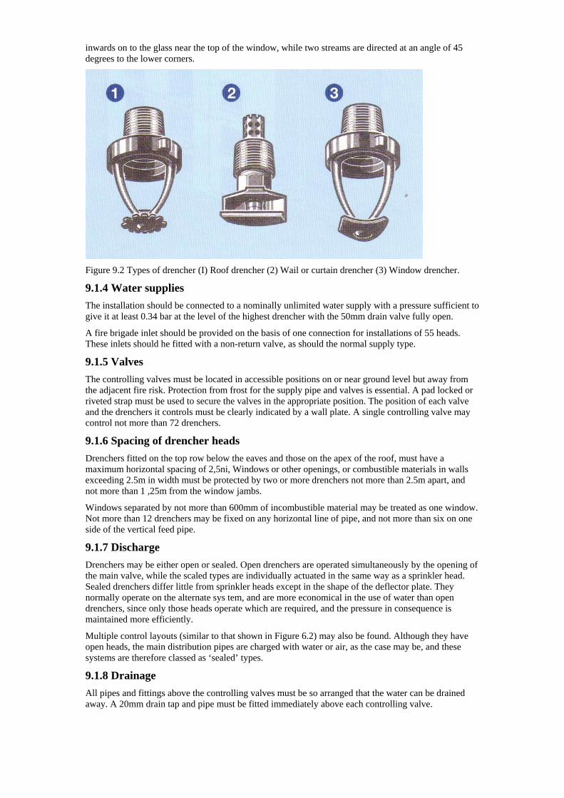
inwards on to the glass near the top of the window, while two streams are directed at an angle of 45 degrees to the lower corners.
Figure 9.2 Types of drencher (I) Roof drencher (2) Wail or curtain drencher (3) Window drencher.
9.1.4 Water supplies The installation should be connected to a nominally unlimited water supply with a pressure sufficient to give it at least 0.34 bar at the level of the highest drencher with the 50mm drain valve fully open.
A fire brigade inlet should be provided on the basis of one connection for installations of 55 heads. These inlets should he fitted with a non-return valve, as should the normal supply type.
9.1.5 Valves The controlling valves must be located in accessible positions on or near ground level but away from the adjacent fire risk. Protection from frost for the supply pipe and valves is essential. A pad locked or riveted strap must be used to secure the valves in the appropriate position. The position of each valve and the drenchers it controls must be clearly indicated by a wall plate. A single controlling valve may control not more than 72 drenchers.
9.1.6 Spacing of drencher heads Drenchers fitted on the top row below the eaves and those on the apex of the roof, must have a maximum horizontal spacing of 2,5ni, Windows or other openings, or combustible materials in walls exceeding 2.5m in width must be protected by two or more drenchers not more than 2.5m apart, and not more than 1 ,25m from the window jambs.
Windows separated by not more than 600mm of incombustible material may be treated as one window. Not more than 12 drenchers may be fixed on any horizontal line of pipe, and not more than six on one side of the vertical feed pipe.
9.1.7 Discharge Drenchers may be either open or sealed. Open drenchers are operated simultaneously by the opening of the main valve, while the scaled types are individually actuated in the same way as a sprinkler head. Sealed drenchers differ little from sprinkler heads except in the shape of the deflector plate. They normally operate on the alternate sys tem, and are more economical in the use of water than open drenchers, since only those heads operate which are required, and the pressure in consequence is maintained more efficiently.
Multiple control layouts (similar to that shown in Figure 6.2) may also be found. Although they have open heads, the main distribution pipes are charged with water or air, as the case may be, and these systems are therefore classed as ‘sealed’ types.
9.1.8 Drainage All pipes and fittings above the controlling valves must be so arranged that the water can be drained away. A 20mm drain tap and pipe must be fitted immediately above each controlling valve.
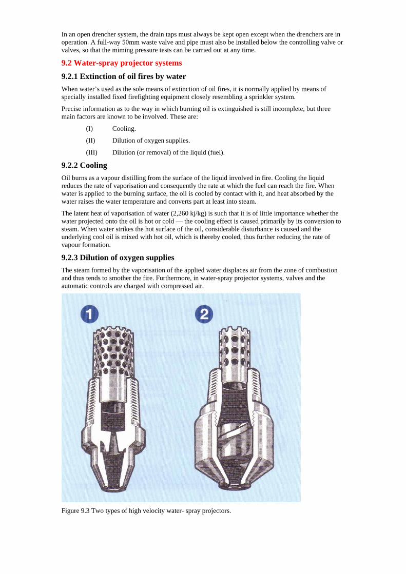
In an open drencher system, the drain taps must always be kept open except when the drenchers are in operation. A full-way 50mm waste valve and pipe must also be installed below the controlling valve or valves, so that the miming pressure tests can be carried out at any time.
9.2 Water-spray projector systems
9.2.1 Extinction of oil fires by water When water’s used as the sole means of extinction of oil fires, it is normally applied by means of specially installed fixed firefighting equipment closely resembling a sprinkler system.
Precise information as to the way in which burning oil is extinguished is still incomplete, but three main factors are known to be involved. These are:
(I) Cooling.
(II) Dilution of oxygen supplies.
(III) Dilution (or removal) of the liquid (fuel).
9.2.2 Cooling Oil burns as a vapour distilling from the surface of the liquid involved in fire. Cooling the liquid reduces the rate of vaporisation and consequently the rate at which the fuel can reach the fire. When water is applied to the burning surface, the oil is cooled by contact with it, and heat absorbed by the water raises the water temperature and converts part at least into steam.
The latent heat of vaporisation of water (2,260 kj/kg) is such that it is of little importance whether the water projected onto the oil is hot or cold — the cooling effect is caused primarily by its conversion to steam. When water strikes the hot surface of the oil, considerable disturbance is caused and the underlying cool oil is mixed with hot oil, which is thereby cooled, thus further reducing the rate of vapour formation.
9.2.3 Dilution of oxygen supplies The steam formed by the vaporisation of the applied water displaces air from the zone of combustion and thus tends to smother the fire. Furthermore, in water-spray projector systems, valves and the automatic controls are charged with compressed air.
Figure 9.3 Two types of high velocity water- spray projectors.
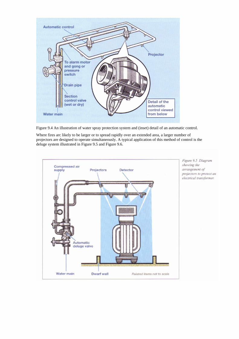
Figure 9.4 An illustration of water spray protection system and (inset) detail of an automatic control.
Where fires arc likely to be larger or to spread rapidly over an extended area, a larger number of projectors are designed to operate simultaneously. A typical application of this method of control is the deluge system illustrated in Figure 9.5 and Figure 9.6.
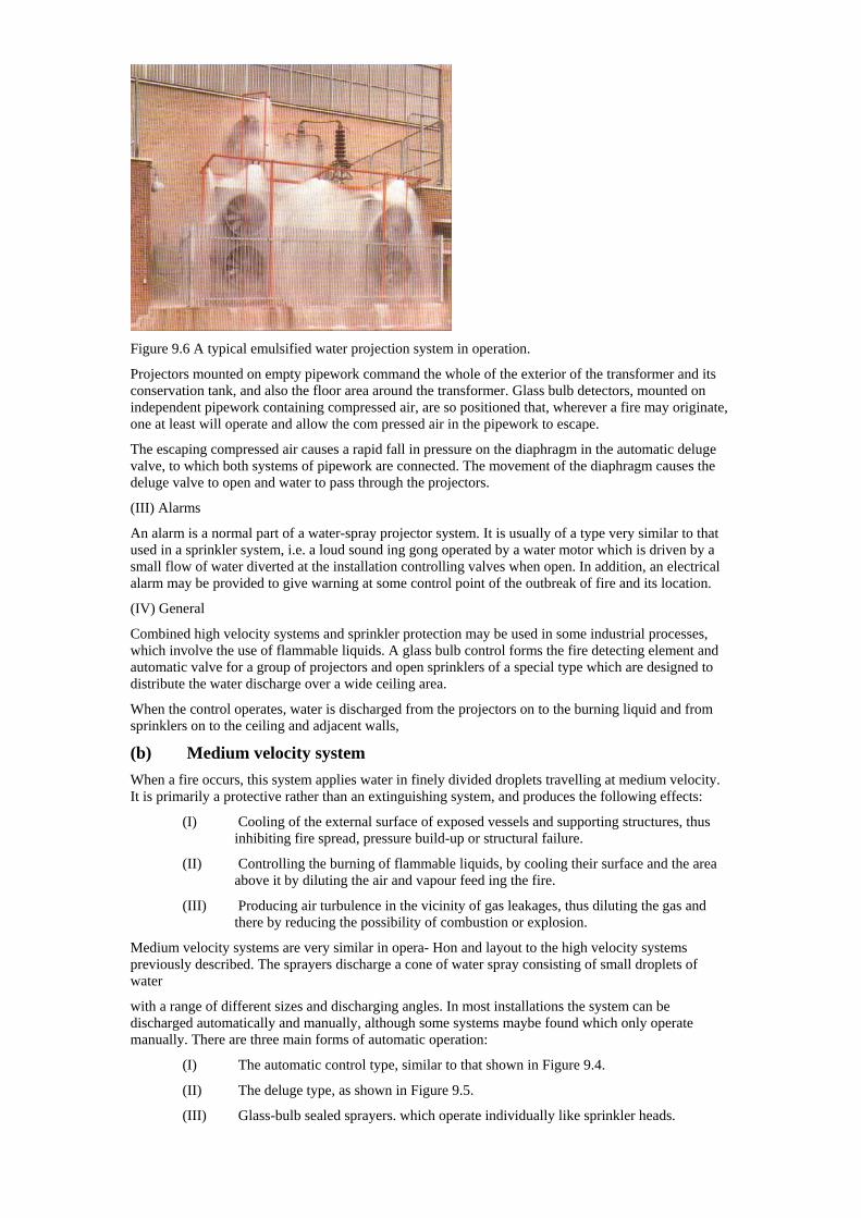
Figure 9.6 A typical emulsified water projection system in operation.
Projectors mounted on empty pipework command the whole of the exterior of the transformer and its conservation tank, and also the floor area around the transformer. Glass bulb detectors, mounted on independent pipework containing compressed air, are so positioned that, wherever a fire may originate, one at least will operate and allow the com pressed air in the pipework to escape.
The escaping compressed air causes a rapid fall in pressure on the diaphragm in the automatic deluge valve, to which both systems of pipework are connected. The movement of the diaphragm causes the deluge valve to open and water to pass through the projectors.
(III) Alarms
An alarm is a normal part of a water-spray projector system. It is usually of a type very similar to that used in a sprinkler system, i.e. a loud sound ing gong operated by a water motor which is driven by a small flow of water diverted at the installation controlling valves when open. In addition, an electrical alarm may be provided to give warning at some control point of the outbreak of fire and its location.
(IV) General
Combined high velocity systems and sprinkler protection may be used in some industrial processes, which involve the use of flammable liquids. A glass bulb control forms the fire detecting element and automatic valve for a group of projectors and open sprinklers of a special type which are designed to distribute the water discharge over a wide ceiling area.
When the control operates, water is discharged from the projectors on to the burning liquid and from sprinklers on to the ceiling and adjacent walls,
(b) Medium velocity system When a fire occurs, this system applies water in finely divided droplets travelling at medium velocity. It is primarily a protective rather than an extinguishing system, and produces the following effects:
(I) Cooling of the external surface of exposed vessels and supporting structures, thus inhibiting fire spread, pressure build-up or structural failure.
(II) Controlling the burning of flammable liquids, by cooling their surface and the area above it by diluting the air and vapour feed ing the fire.
(III) Producing air turbulence in the vicinity of gas leakages, thus diluting the gas and there by reducing the possibility of combustion or explosion.
Medium velocity systems are very similar in opera- Hon and layout to the high velocity systems previously described. The sprayers discharge a cone of water spray consisting of small droplets of water
with a range of different sizes and discharging angles. In most installations the system can be discharged automatically and manually, although some systems maybe found which only operate manually. There are three main forms of automatic operation:
(I) The automatic control type, similar to that shown in Figure 9.4.
(II) The deluge type, as shown in Figure 9.5.
(III) Glass-bulb sealed sprayers. which operate individually like sprinkler heads.
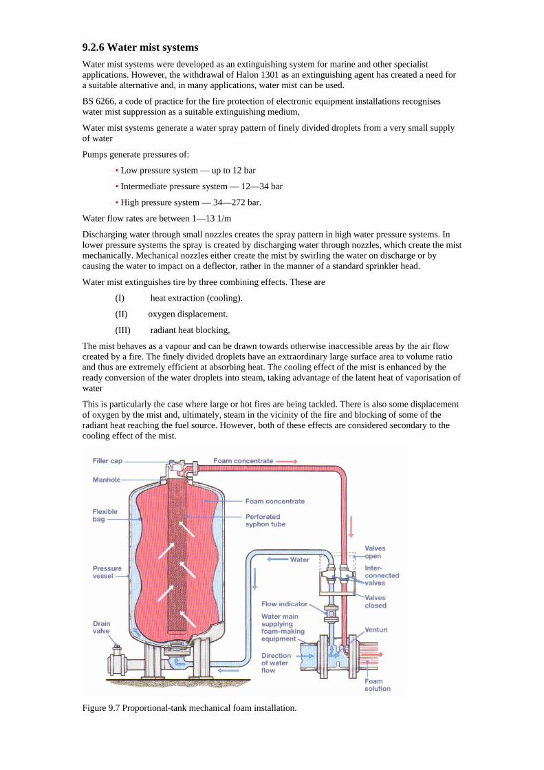
9.2.6 Water mist systems Water mist systems were developed as an extinguishing system for marine and other specialist applications. However, the withdrawal of Halon 1301 as an extinguishing agent has created a need for a suitable alternative and, in many applications, water mist can be used.
BS 6266, a code of practice for the fire protection of electronic equipment installations recognises water mist suppression as a suitable extinguishing medium,
Water mist systems generate a water spray pattern of finely divided droplets from a very small supply of water
Pumps generate pressures of:
• Low pressure system — up to 12 bar
• Intermediate pressure system — 12—34 bar
• High pressure system — 34—272 bar.
Water flow rates are between 1—13 1/m
Discharging water through small nozzles creates the spray pattern in high water pressure systems. In lower pressure systems the spray is created by discharging water through nozzles, which create the mist mechanically. Mechanical nozzles either create the mist by swirling the water on discharge or by causing the water to impact on a deflector, rather in the manner of a standard sprinkler head.
Water mist extinguishes tire by three combining effects. These are
(I) heat extraction (cooling).
(II) oxygen displacement.
(III) radiant heat blocking,
The mist behaves as a vapour and can be drawn towards otherwise inaccessible areas by the air flow created by a fire. The finely divided droplets have an extraordinary large surface area to volume ratio and thus are extremely efficient at absorbing heat. The cooling effect of the mist is enhanced by the ready conversion of the water droplets into steam, taking advantage of the latent heat of vaporisation of water
This is particularly the case where large or hot fires are being tackled. There is also some displacement of oxygen by the mist and, ultimately, steam in the vicinity of the fire and blocking of some of the radiant heat reaching the fuel source. However, both of these effects are considered secondary to the cooling effect of the mist.
Figure 9.7 Proportional-tank mechanical foam installation.
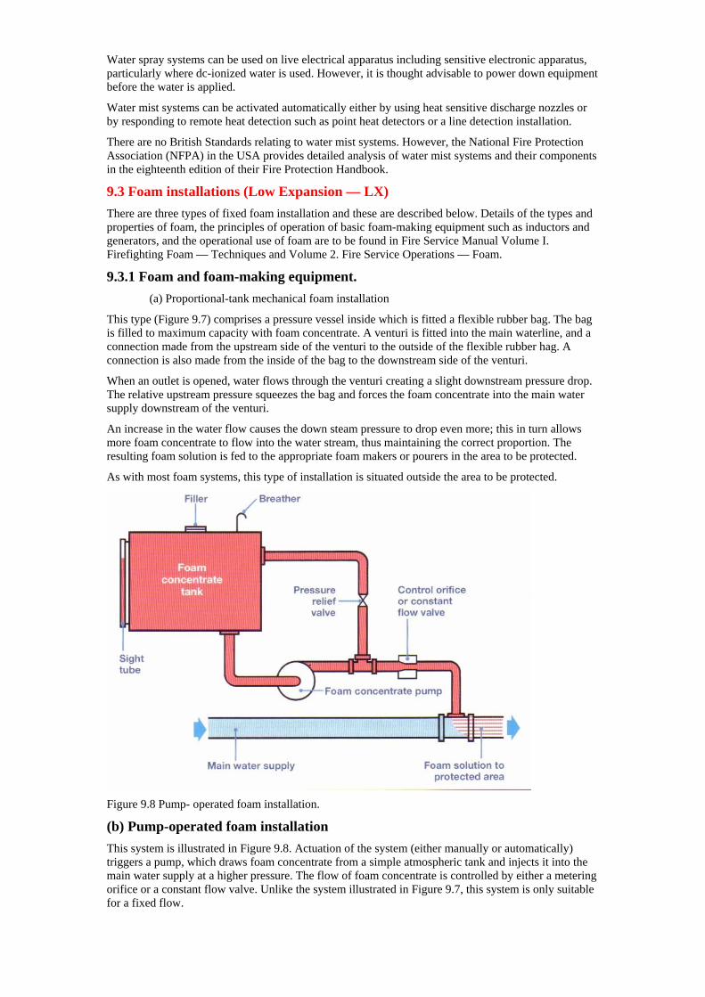
Water spray systems can be used on live electrical apparatus including sensitive electronic apparatus, particularly where dc-ionized water is used. However, it is thought advisable to power down equipment before the water is applied.
Water mist systems can be activated automatically either by using heat sensitive discharge nozzles or by responding to remote heat detection such as point heat detectors or a line detection installation.
There are no British Standards relating to water mist systems. However, the National Fire Protection Association (NFPA) in the USA provides detailed analysis of water mist systems and their components in the eighteenth edition of their Fire Protection Handbook.
9.3 Foam installations (Low Expansion — LX) There are three types of fixed foam installation and these are described below. Details of the types and properties of foam, the principles of operation of basic foam-making equipment such as inductors and generators, and the operational use of foam are to be found in Fire Service Manual Volume I. Firefighting Foam — Techniques and Volume 2. Fire Service Operations — Foam.
9.3.1 Foam and foam-making equipment. (a) Proportional-tank mechanical foam installation
This type (Figure 9.7) comprises a pressure vessel inside which is fitted a flexible rubber bag. The bag is filled to maximum capacity with foam concentrate. A venturi is fitted into the main waterline, and a connection made from the upstream side of the venturi to the outside of the flexible rubber hag. A connection is also made from the inside of the bag to the downstream side of the venturi.
When an outlet is opened, water flows through the venturi creating a slight downstream pressure drop. The relative upstream pressure squeezes the bag and forces the foam concentrate into the main water supply downstream of the venturi.
An increase in the water flow causes the down steam pressure to drop even more; this in turn allows more foam concentrate to flow into the water stream, thus maintaining the correct proportion. The resulting foam solution is fed to the appropriate foam makers or pourers in the area to be protected.
As with most foam systems, this type of installation is situated outside the area to be protected.
Figure 9.8 Pump- operated foam installation.
(b) Pump-operated foam installation This system is illustrated in Figure 9.8. Actuation of the system (either manually or automatically) triggers a pump, which draws foam concentrate from a simple atmospheric tank and injects it into the main water supply at a higher pressure. The flow of foam concentrate is controlled by either a metering orifice or a constant flow valve. Unlike the system illustrated in Figure 9.7, this system is only suitable for a fixed flow.
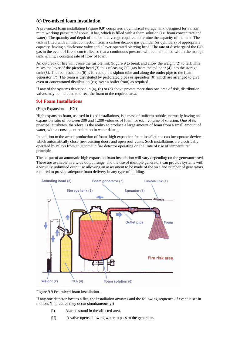
(c) Pre-mixed foam installation A pre-mixed foam installation (Figure 9.9) comprises a cylindrical storage tank, designed for a maxi mum working pressure of about 10 bar, which is filled with a foam solution (i.e. foam concentrate and water). The quantity and depth of the foam coverage required determine the capacity of the tank. The tank is fitted with an inlet connection from a carbon dioxide gas cylinder (or cylinders) of appropriate capacity. having a disclosure valve and a lever-operated piercing head. The rate of discharge of the CO. gas in the event of fire is con trolled so that a continuous pressure will be maintained within the storage tank, giving a constant rate of flow of foam.
An outbreak of fire will cause the fusible link (Figure 9 to break and allow the weight (2) to fall. This raises the lever of the piercing head (3) thus releasing CO. gas from the cylinder (4) into the storage tank (5). The foam solution (6) is forced up the siphon tube and along the outlet pipe to the foam generator (7). The foam is distributed by perforated pipes or spreaders (8) which are arranged to give even or concentrated distribution (e.g. over a boiler front) as required.
If any of the systems described in (a), (b) or (c) above protect more than one area of risk, distribution valves may be included to direct the foam to the required area.
9.4 Foam Installations (High Expansion — HX)
High expansion foam, as used in fixed installations, is a mass of uniform bubbles normally having an expansion ratio of between 200 and 1:200 volumes of foam for each volume of solution. One of its principal attributes, therefore, is the ability to produce a large amount of foam from a small amount of water, with a consequent reduction in water damage.
In addition to the actual production of foam, high expansion foam installations can incorporate devices which automatically close fire-resisting doors and open roof vents. Such installations are electrically operated by relays from an automatic fire detector operating on the ‘rate of rise of temperature’ principle.
The output of an automatic high expansion foam installation will vary depending on the generator used. These are available in a wide output range, and the use of multiple generators can provide systems with a virtually unlimited output so allowing an assessment to be made of the size and number of generators required to provide adequate foam delivery in any type of building.
Figure 9.9 Pre-mixed foam installation.
If any one detector locates a fire, the installation actuates and the following sequence of event is set in motion. (In practice they occur simultaneously.)
(I) Alarms sound in the affected area.
(II) A valve opens allowing water to pass to the generator.
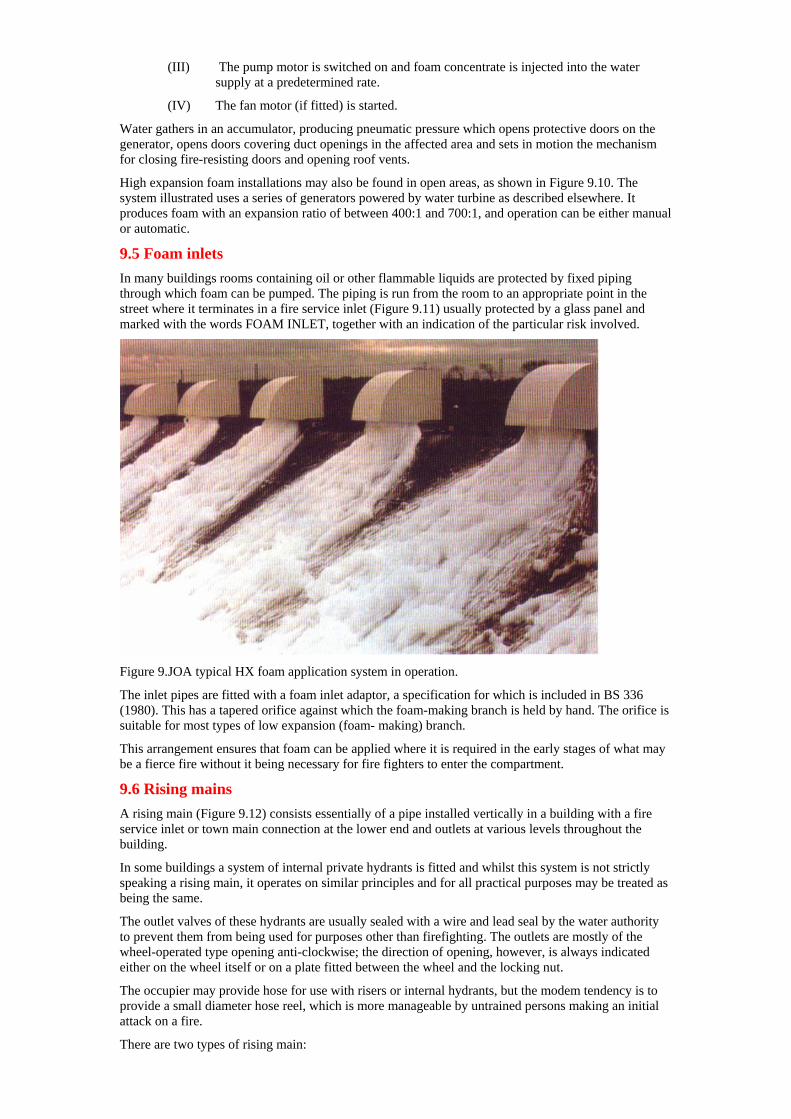
(III) The pump motor is switched on and foam concentrate is injected into the water supply at a predetermined rate.
(IV) The fan motor (if fitted) is started.
Water gathers in an accumulator, producing pneumatic pressure which opens protective doors on the generator, opens doors covering duct openings in the affected area and sets in motion the mechanism for closing fire-resisting doors and opening roof vents.
High expansion foam installations may also be found in open areas, as shown in Figure 9.10. The system illustrated uses a series of generators powered by water turbine as described elsewhere. It produces foam with an expansion ratio of between 400:1 and 700:1, and operation can be either manual or automatic.
9.5 Foam inlets In many buildings rooms containing oil or other flammable liquids are protected by fixed piping through which foam can be pumped. The piping is run from the room to an appropriate point in the street where it terminates in a fire service inlet (Figure 9.11) usually protected by a glass panel and marked with the words FOAM INLET, together with an indication of the particular risk involved.
Figure 9.JOA typical HX foam application system in operation.
The inlet pipes are fitted with a foam inlet adaptor, a specification for which is included in BS 336 (1980). This has a tapered orifice against which the foam-making branch is held by hand. The orifice is suitable for most types of low expansion (foam- making) branch.
This arrangement ensures that foam can be applied where it is required in the early stages of what may be a fierce fire without it being necessary for fire fighters to enter the compartment.
9.6 Rising mains A rising main (Figure 9.12) consists essentially of a pipe installed vertically in a building with a fire service inlet or town main connection at the lower end and outlets at various levels throughout the building.
In some buildings a system of internal private hydrants is fitted and whilst this system is not strictly speaking a rising main, it operates on similar principles and for all practical purposes may be treated as being the same.
The outlet valves of these hydrants are usually sealed with a wire and lead seal by the water authority to prevent them from being used for purposes other than firefighting. The outlets are mostly of the wheel-operated type opening anti-clockwise; the direction of opening, however, is always indicated either on the wheel itself or on a plate fitted between the wheel and the locking nut.
The occupier may provide hose for use with risers or internal hydrants, but the modem tendency is to provide a small diameter hose reel, which is more manageable by untrained persons making an initial attack on a fire.
There are two types of rising main:
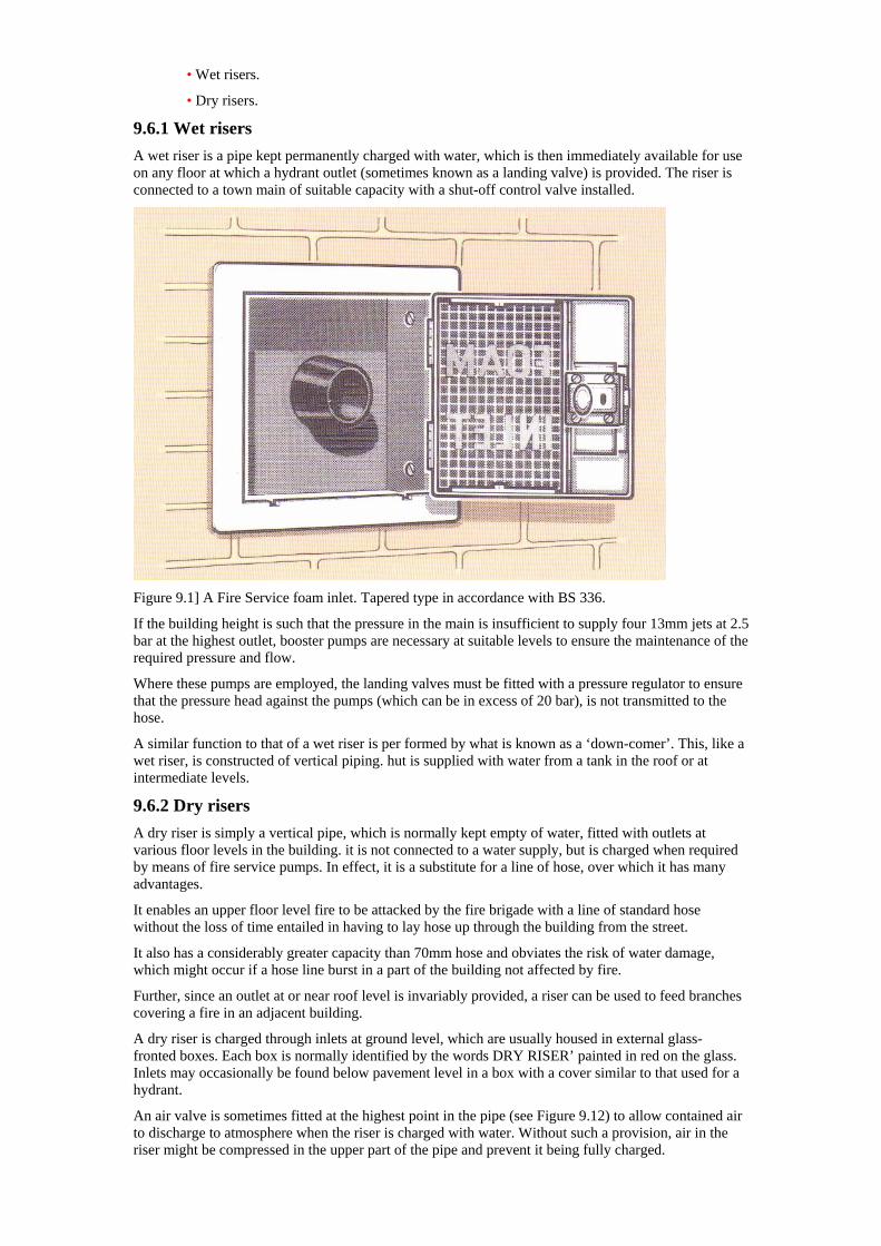
• Wet risers.
• Dry risers.
9.6.1 Wet risers A wet riser is a pipe kept permanently charged with water, which is then immediately available for use on any floor at which a hydrant outlet (sometimes known as a landing valve) is provided. The riser is connected to a town main of suitable capacity with a shut-off control valve installed.
Figure 9.1] A Fire Service foam inlet. Tapered type in accordance with BS 336.
If the building height is such that the pressure in the main is insufficient to supply four 13mm jets at 2.5 bar at the highest outlet, booster pumps are necessary at suitable levels to ensure the maintenance of the required pressure and flow.
Where these pumps are employed, the landing valves must be fitted with a pressure regulator to ensure that the pressure head against the pumps (which can be in excess of 20 bar), is not transmitted to the hose.
A similar function to that of a wet riser is per formed by what is known as a ‘down-comer’. This, like a wet riser, is constructed of vertical piping. hut is supplied with water from a tank in the roof or at intermediate levels.
9.6.2 Dry risers A dry riser is simply a vertical pipe, which is normally kept empty of water, fitted with outlets at various floor levels in the building. it is not connected to a water supply, but is charged when required by means of fire service pumps. In effect, it is a substitute for a line of hose, over which it has many advantages.
It enables an upper floor level fire to be attacked by the fire brigade with a line of standard hose without the loss of time entailed in having to lay hose up through the building from the street.
It also has a considerably greater capacity than 70mm hose and obviates the risk of water damage, which might occur if a hose line burst in a part of the building not affected by fire.
Further, since an outlet at or near roof level is invariably provided, a riser can be used to feed branches covering a fire in an adjacent building.
A dry riser is charged through inlets at ground level, which are usually housed in external glass- fronted boxes. Each box is normally identified by the words DRY RISER’ painted in red on the glass. Inlets may occasionally be found below pavement level in a box with a cover similar to that used for a hydrant.
An air valve is sometimes fitted at the highest point in the pipe (see Figure 9.12) to allow contained air to discharge to atmosphere when the riser is charged with water. Without such a provision, air in the riser might be compressed in the upper part of the pipe and prevent it being fully charged.
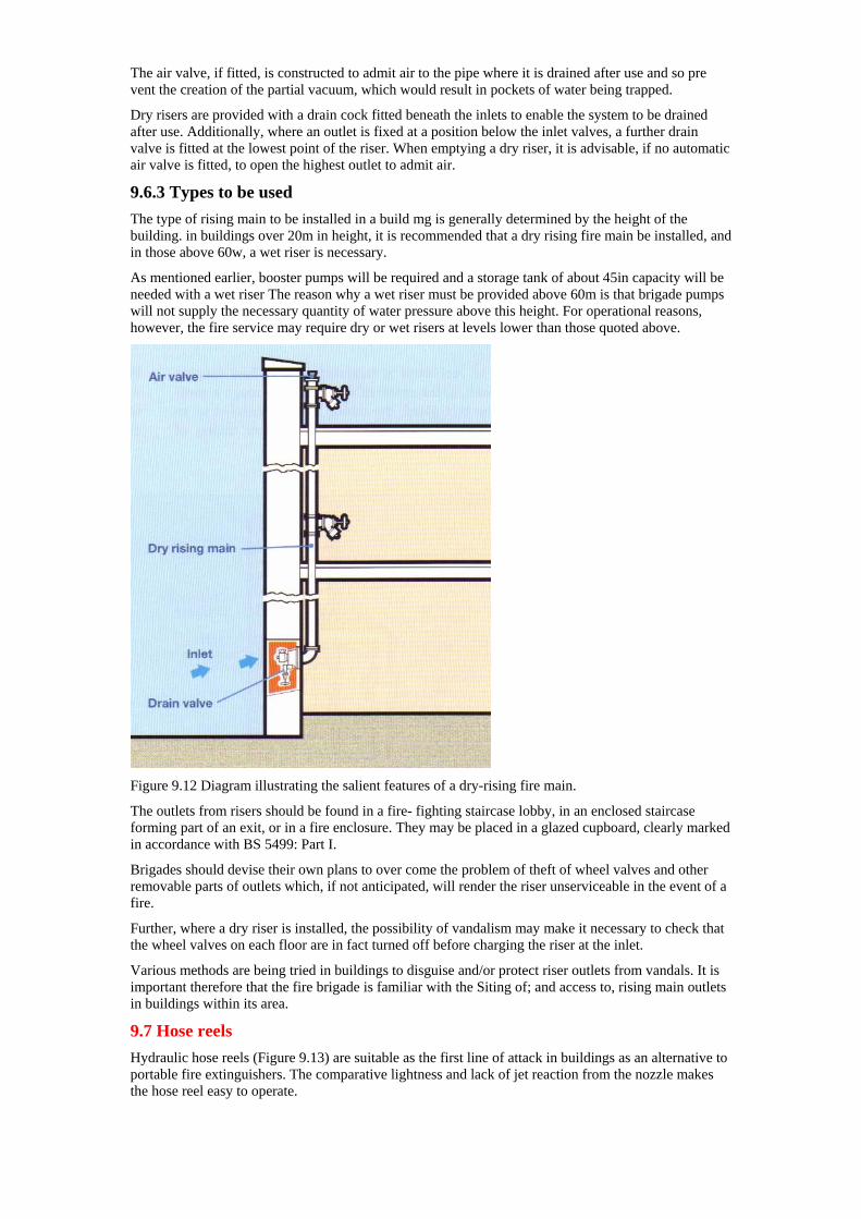
The air valve, if fitted, is constructed to admit air to the pipe where it is drained after use and so pre vent the creation of the partial vacuum, which would result in pockets of water being trapped.
Dry risers are provided with a drain cock fitted beneath the inlets to enable the system to be drained after use. Additionally, where an outlet is fixed at a position below the inlet valves, a further drain valve is fitted at the lowest point of the riser. When emptying a dry riser, it is advisable, if no automatic air valve is fitted, to open the highest outlet to admit air.
9.6.3 Types to be used The type of rising main to be installed in a build mg is generally determined by the height of the building. in buildings over 20m in height, it is recommended that a dry rising fire main be installed, and in those above 60w, a wet riser is necessary.
As mentioned earlier, booster pumps will be required and a storage tank of about 45in capacity will be needed with a wet riser The reason why a wet riser must be provided above 60m is that brigade pumps will not supply the necessary quantity of water pressure above this height. For operational reasons, however, the fire service may require dry or wet risers at levels lower than those quoted above.
Figure 9.12 Diagram illustrating the salient features of a dry-rising fire main.
The outlets from risers should be found in a fire- fighting staircase lobby, in an enclosed staircase forming part of an exit, or in a fire enclosure. They may be placed in a glazed cupboard, clearly marked in accordance with BS 5499: Part I.
Brigades should devise their own plans to over come the problem of theft of wheel valves and other removable parts of outlets which, if not anticipated, will render the riser unserviceable in the event of a fire.
Further, where a dry riser is installed, the possibility of vandalism may make it necessary to check that the wheel valves on each floor are in fact turned off before charging the riser at the inlet.
Various methods are being tried in buildings to disguise and/or protect riser outlets from vandals. It is important therefore that the fire brigade is familiar with the Siting of; and access to, rising main outlets in buildings within its area.
9.7 Hose reels Hydraulic hose reels (Figure 9.13) are suitable as the first line of attack in buildings as an alternative to portable fire extinguishers. The comparative lightness and lack of jet reaction from the nozzle makes the hose reel easy to operate.
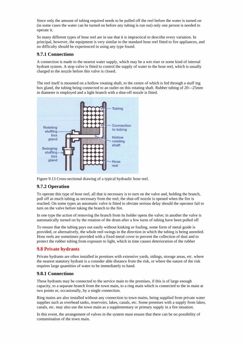
Since only the amount of tubing required needs to be pulled off the reel before the water is turned on (in some cases the water can be turned on before any tubing is run out) only one person is needed to operate it.
So many different types of hose reel are in use that it is impractical to describe every variation. In principal, however, the equipment is very similar to the standard hose reel fitted to fire appliances, and no difficulty should he experienced in using any type found.
9.7.1 Connections A connection is made to the nearest water supply, which may be a wet riser or some kind of internal hydrant system. A stop valve is fitted to control the supply of water to the hose reel, which is usually charged to the nozzle before this valve is closed.
The reel itself is mounted on a hollow rotating shaft, to the centre of which is fed through a stuff ing box gland, the tubing being connected to an outlet on this rotating shaft. Rubber tubing of 20—25mm in diameter is employed and a light branch with a shut-off nozzle is fitted.
Figure 9.13 Cross-sectional drawing of a typical hydraulic hose reel.
9.7.2 Operation To operate this type of hose reel, all that is necessary is to turn on the valve and, holding the branch, pull off as much tubing as necessary from the reel; the shut-off nozzle is opened when the fire is reached. On some types an automatic valve is fitted to obviate serious delay should the operator fail to turn on the valve before taking the branch to the fire.
In one type the action of removing the branch from its holder opens the valve; in another the valve is automatically turned on by the rotation of the drum after a few turns of tubing have been pulled off
To ensure that the tubing pays out easily without kinking or fouling, some form of metal guide is provided, or alternatively, the whole reel swings in the direction in which the tubing is being unreeled. Hose reels are sometimes provided with a fixed metal cover to prevent the collection of dust and to protect the rubber tubing from exposure to light, which in time causes deterioration of the rubber
9.8 Private hydrants Private hydrants are often installed in premises with extensive yards, sidings, storage areas, etc. where the nearest statutory hydrant is a consider able distance from the risk, or where the nature of the risk requires large quantities of water to be immediately to hand.
9.8.1 Connections These hydrants may be connected to the service main to the premises, if this is of large enough capacity, to a separate branch from the town main, to a ring main which is connected to the to main at two points or, occasionally, by a single connection.
Ring mains are also installed without any connection to town mains, being supplied from private water supplies such as overhead tanks, reservoirs, lakes, canals, etc. Some premises with a supply from lakes, canals, etc. may also use the town main as a supplementary or primary supply in a fire situation.
In this event, the arrangement of valves in the system must ensure that there can be no possibility of contamination of the town main.
A ring main installation has many obvious advantages. The most important is that any hydrant is fed by both arms of the ring, since a division valve is fitted in connections with the town main or other water supply and, sometimes, at intermediate points.
It may be possible to isolate a damaged section and thus allow a portion of the ring to remain in action. Where premises are equipped with a sprinkler system as well as private hydrants, separate branches should be provided for each.
9.8.2 Hydrant markings Increasing use is being made of standard hydrant indicator plates (see also Fire Service Manual, Volume 1 Fire Service Technology, Equipment and Media — Hydraulics. Pumps and Water Supplies) to mark the position of private hydrants, although various individual markings may still be found. The hydrants themselves are of various patterns, the most common being the standard underground hydrant; less common are pillar hydrants and wall hydrants.
9.8.3 Outlets The outlets of private hydrants usually conform to BS 750, although other types may be found. Where private hydrants are non-standard, adaptors should be provided at the premises to enable fire brigade equipment to be used.
9.8.4 By-pass valves As private mains usually supply the domestic needs of the premises, they are almost always fitted with a water meter so that the water undertakings can record the consumption. Where water is fed into industrial premises for business purposes through a meter, it is common practice for a by pass to be fitted.
If water on the factory side of the meter is required for firefighting, the meter can be by-passed by opening the by-pass valve, thus eliminating frictional resistance through the meter. In addition, the water used for firefighting does not register on the meter.
The location of the valve controlling a meter by pass should be indicated by a standard by-pass indicator plate (see Fire Service Manual, Volume I Fire Service Technology, Equipment and Media
Hydraulics, Pumps and Water Supplies.). The valve is usually wire-locked in the closed position and when a hydrant is used for fire fighting, the valve should be opened fully to enable the maxi mum flow to be obtained.
Chapter 10— Extinguishing systems not using water This chapter deals with the equipment and fittings installed to protect buildings by means other than the use of water A firefighter needs to be familiar with the types of media used in the installations. They include carbon dioxide and halon systems with a brief mention of powder and inert gas equipment.
10.1 Carbon Dioxide (C0 installations)
10.1.1 Applications and limitations of carbon dioxide The use of carbon dioxide installations is confined primarily to hazards which are located inside buildings, or around which protective screens can be erected. Although heavier than air, the gas may be dispersed away from the fire if subjected to any appreciable currents of air.
The gas discharges at low temperature, but this does not produce much cooling effect in the fire area and is never taken into consideration when designing an installation, dilution of the atmosphere being the main extinguishing effect.
Carbon dioxide is not suitable for extinguishing fires involving materials which contain their own oxygen supply, e.g. nitrates, chlorates or reactive metals such as sodium, potassium, magnesium, etc. It has a particular application where delicate equipment or materials are involved and some examples of the type of risk where it can be used satisfactorily are:
(I) A wide variety of electrical apparatus and electronic equipment, e.g. electrical switch- gear, transformers, alternators, computers, and telephone relays and repeater stations.
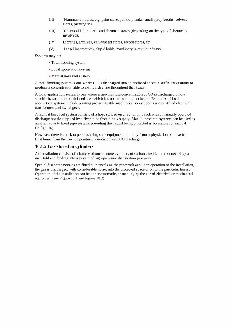
(II) Flammable liquids, e.g. paint store, paint dip tanks, small spray booths, solvent stores, printing ink.
(III) Chemical laboratories and chemical stores (depending on the type of chemicals involved).
(IV) Libraries, archives, valuable art stores, record stores, etc.
(V) Diesel locomotives, ships’ holds, machinery in textile industry.
Systems may be:
• Total flooding system
• Local application system
• Manual hose reel system.
A total flooding system is one where CO is discharged into an enclosed space in sufficient quantity to produce a concentration able to extinguish a fire throughout that space.
A local application system is one where a fire- fighting concentration of CO is discharged onto a specific hazard or into a defined area which has no surrounding enclosure. Examples of local application systems include printing presses, textile machinery, spray booths and oil-filled electrical transformers and switchgear.
A manual hose reel system consists of a hose stowed on a reel or on a rack with a manually operated discharge nozzle supplied by a fixed pipe from a bulk supply. Manual hose reel systems can be used as an alternative to fixed pipe systems providing the hazard being protected is accessible for manual firefighting.
However, there is a risk to persons using such equipment, not only from asphyxiation but also from frost bums from the low temperatures associated with CO discharge.
10.1.2 Gas stored in cylinders An installation consists of a battery of one or more cylinders of carbon dioxide interconnected by a manifold and feeding into a system of high-pres sure distribution pipework.
Special discharge nozzles are fitted at intervals on the pipework and upon operation of the installation, the gas is discharged, with considerable noise, into the protected space or on to the particular hazard. Operation of the installation can be either automatic, or manual, by the use of electrical or mechanical equipment (see Figure 10.1 and Figure 10.2).
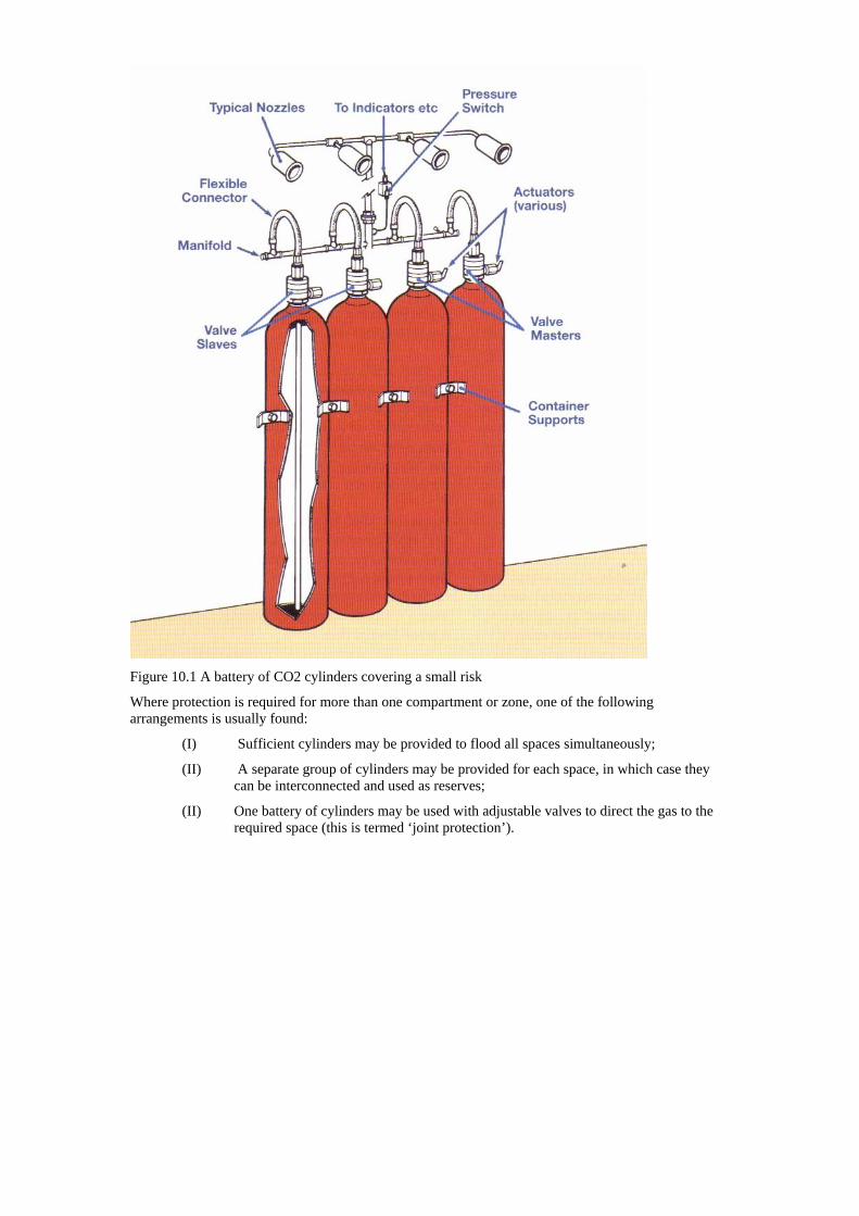
Figure 10.1 A battery of CO2 cylinders covering a small risk
Where protection is required for more than one compartment or zone, one of the following arrangements is usually found:
(I) Sufficient cylinders may be provided to flood all spaces simultaneously;
(II) A separate group of cylinders may be provided for each space, in which case they can be interconnected and used as reserves;
(II) One battery of cylinders may be used with adjustable valves to direct the gas to the required space (this is termed ‘joint protection’).
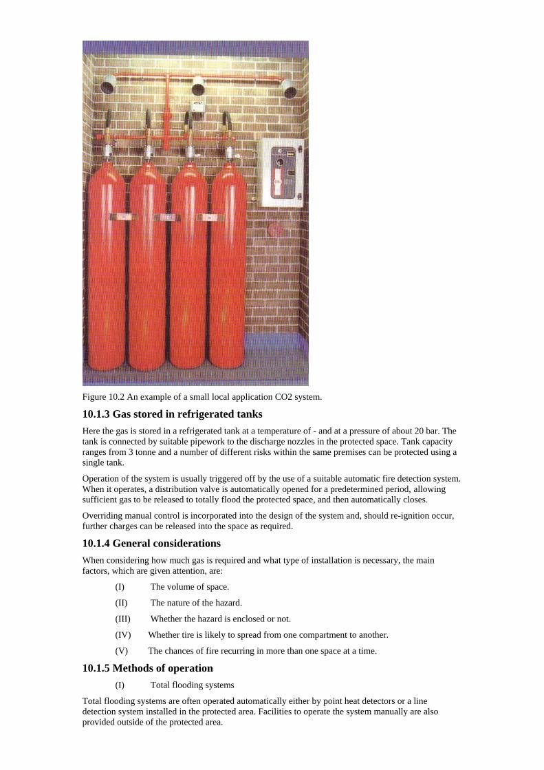
Figure 10.2 An example of a small local application CO2 system.
10.1.3 Gas stored in refrigerated tanks Here the gas is stored in a refrigerated tank at a temperature of - and at a pressure of about 20 bar. The tank is connected by suitable pipework to the discharge nozzles in the protected space. Tank capacity ranges from 3 tonne and a number of different risks within the same premises can be protected using a single tank.
Operation of the system is usually triggered off by the use of a suitable automatic fire detection system. When it operates, a distribution valve is automatically opened for a predetermined period, allowing sufficient gas to be released to totally flood the protected space, and then automatically closes.
Overriding manual control is incorporated into the design of the system and, should re-ignition occur, further charges can be released into the space as required.
10.1.4 General considerations When considering how much gas is required and what type of installation is necessary, the main factors, which are given attention, are:
(I) The volume of space.
(II) The nature of the hazard.
(III) Whether the hazard is enclosed or not.
(IV) Whether tire is likely to spread from one compartment to another.
(V) The chances of fire recurring in more than one space at a time.
10.1.5 Methods of operation (I) Total flooding systems
Total flooding systems are often operated automatically either by point heat detectors or a line detection system installed in the protected area. Facilities to operate the system manually are also provided outside of the protected area.
Activation of the system is indicated by a system alarm in the protected area. The system alarm should also trigger the general fire alarm in the building. Locks off devices are provided to prevent the discharge of CO whilst persons are in the protected area. (See Section 10.1 below.)
(II) Local application systems
Local application systems are operated in much the same way as total flooding systems except that where people can leave the space in which the discharge takes place, no lock-off provision is made.
If it is necessary for people to work close to the hazard protected by a local application system where they might be enveloped with CO gas, a pre-discharge alarm is provided. This will give them sufficient time to evacuate the area before C0 is released,
Where it may be difficult for people to make a rapid exit, such as maintenance workers servicing plant protected by a local application system, lock- off devices will be provided.
10.1.6 Lock-off devices Lock-off devices are designed to:
(I) Disable the automatic operation of a CO system. The device will ‘lock-off’ the automatic feature only (leaving overriding manual control).
(II) Completely immobilise the installation.
These devices can usually be operated from a remote position outside the protected area.
10.1.7 Indicating and alarm devices Automatic visual warning, using a system of coloured indicator lights, is usually provided to indicate:
(I) Manual control.
(II) Automatic control.
(III) Carbon dioxide discharged.
In addition, visible and/or audible warning may be provided to indicate an electrical fault. All indicators may terminate at a central control where necessary, in addition to a warning on site.
10.1.8 Other automatic devices By diverting a small amount of gas to pressure- operated switches and trip mechanisms it is possible automatically to:
(I) Operate door-closing devices.
(II) Close openings in ventilating ducts.
(III) Switch off ventilating systems.
(IV) Operate fire curtains.
10.1.9 General safety precautions Aisles and routes of exits should be kept clear at all times. Adequate lighting and/or emergency lighting with directional signs to ensure quick staff evacuation may be necessary for large protected chambers. Sufficient alarms should be provided within the area to operate immediately upon detection of fire and at the time of CO discharge.
Alternatively, the alarms should sound for a timed interval before operation of the CO installation.
Automatic closure of doors should not prevent the doors being reopened by trapped personnel. Outward-swinging self-closing doors are recommended.
Warning and instructional signs or notices should be positioned at the entrance to protected tire risks. In most eases where CQ is installed, the actual hazard to personnel is rather small, but the hazard will always be greater where the enclosure is large and where carbon dioxide may enter adjacent spaces such as pits and basements.
The extent and type of warning must be designed to suit the particular site but it should always include the symbol shown in Figure 10 Usually, adequate warning notices, bells and indicating lights are provided with an installation for the guidance of staff and it is recommended that fire fighters should comply with the instructions given on such notices.

Instruction and drills should be carried out to ensure that correct action is taken by staff when the equipment operates. Provision should be made for the prompt ventilation of areas into which CO has been discharged. The hazardous atmosphere should be dissipated and not merely transferred to another area.
Figure 10.3 Standard CO2, warning symbol.
10.1.10 Action by the Fire Service In addition being an asphyxiant carbon dioxide should be regarded: as a toxic gas. Exposure to atmospheres containing about 5% CO2, leads to shortage of breath Mild headache. Concentrations of around 10% can cause Visual disturbance, ringing in the ears and tremor, followed by loss of consciousness. Concentrations for firefighting often exceed 3O% Breathing apparatus must be worn by personnel entering area in which a CO. installation has been discharged
CO2 is denser than air and will accumulate at lower levels. Care should be taken to ensure that areas likely to contain residual pockets of CO2 gas are thoroughly ventilated before being entered by unprotected personnel.
10.2 Halon installations Halon has been identified as a source of ozone depletion. Consequently, European and UK legislation requires that, except for a very few ‘critical situations’, all halon installations must be decommissioned by the 31 December 2003.
In addition, no system can be refilled after 1 January 2003. The decommissioning of halon systems must be undertaken by a person certificated as being competent in the disposal of redundant halon. Under no circumstances should halon be released into the atmosphere.
Brigades having halon installations in their area under the ‘critical user’ definition should ensure that personnel likely to be called to an incident involving the discharge of halon are familiar with the safety precautions to be taken.
At the time of writing (2003) various halon alter native gaseous products are coming onto the market. Where these systems are known to exist, the safety procedures outlined for CO installations should be adopted.
10.3 Powder installations Powder provides a further range of chemical agents available as extinguishing media, and the properties of these are dealt with in the Manual of Firemanship, Book 3 Chapter 5. In common with halons, powders offer the advantage of a quick knock-down of fire, but unlike halons, they have negligible toxic effects.
A major disadvantage is that powders require a lot of clearing up once an installation has operated. Compacting of the powder is also a problem, due to heat or vibration in normal storage and in moist atmospheres; this could present difficulties in the maintenance of the system, especially after discharge when compacting could take place in valves, etc. The more recently developed powders however, do not have this problem.
A dry powder installation consists of specially designed pipework and discharge nozzles covering the protected risk, the pipework being linked to the powder containers. When a fire occurs it is necessary to exert pressure on the powder so that it is forced through the pipework and discharge nozzles. This is
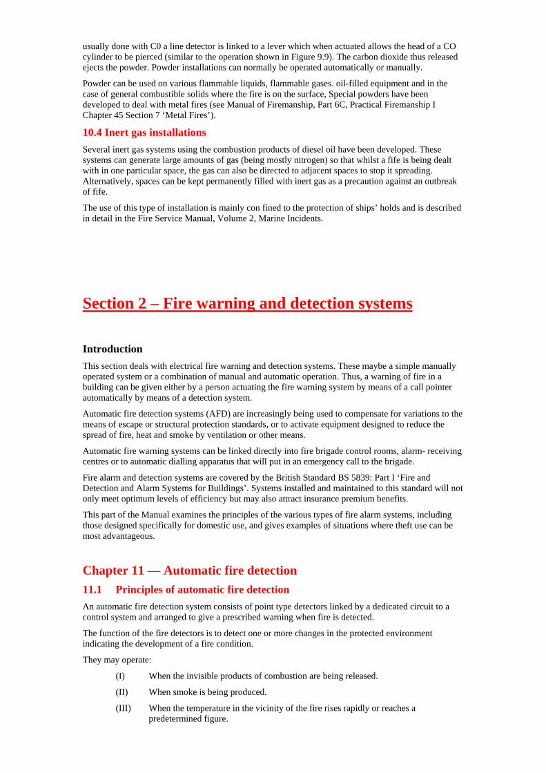
usually done with C0 a line detector is linked to a lever which when actuated allows the head of a CO cylinder to be pierced (similar to the operation shown in Figure 9.9). The carbon dioxide thus released ejects the powder. Powder installations can normally be operated automatically or manually.
Powder can be used on various flammable liquids, flammable gases. oil-filled equipment and in the case of general combustible solids where the fire is on the surface, Special powders have been developed to deal with metal fires (see Manual of Firemanship, Part 6C, Practical Firemanship I Chapter 45 Section 7 ‘Metal Fires’).
10.4 Inert gas installations Several inert gas systems using the combustion products of diesel oil have been developed. These systems can generate large amounts of gas (being mostly nitrogen) so that whilst a fife is being dealt with in one particular space, the gas can also be directed to adjacent spaces to stop it spreading. Alternatively, spaces can be kept permanently filled with inert gas as a precaution against an outbreak of fife.
The use of this type of installation is mainly con fined to the protection of ships’ holds and is described in detail in the Fire Service Manual, Volume 2, Marine Incidents.
Section 2 – Fire warning and detection systems Introduction This section deals with electrical fire warning and detection systems. These maybe a simple manually operated system or a combination of manual and automatic operation. Thus, a warning of fire in a building can be given either by a person actuating the fire warning system by means of a call pointer automatically by means of a detection system.
Automatic fire detection systems (AFD) are increasingly being used to compensate for variations to the means of escape or structural protection standards, or to activate equipment designed to reduce the spread of fire, heat and smoke by ventilation or other means.
Automatic fire warning systems can be linked directly into fire brigade control rooms, alarm- receiving centres or to automatic dialling apparatus that will put in an emergency call to the brigade.
Fire alarm and detection systems are covered by the British Standard BS 5839: Part I ‘Fire and Detection and Alarm Systems for Buildings’. Systems installed and maintained to this standard will not only meet optimum levels of efficiency but may also attract insurance premium benefits.
This part of the Manual examines the principles of the various types of fire alarm systems, including those designed specifically for domestic use, and gives examples of situations where theft use can be most advantageous.
Chapter 11 — Automatic fire detection 11.1 Principles of automatic fire detection An automatic fire detection system consists of point type detectors linked by a dedicated circuit to a control system and arranged to give a prescribed warning when fire is detected.
The function of the fire detectors is to detect one or more changes in the protected environment indicating the development of a fire condition.
They may operate:
(I) When the invisible products of combustion are being released.
(II) When smoke is being produced.
(III) When the temperature in the vicinity of the fire rises rapidly or reaches a predetermined figure.
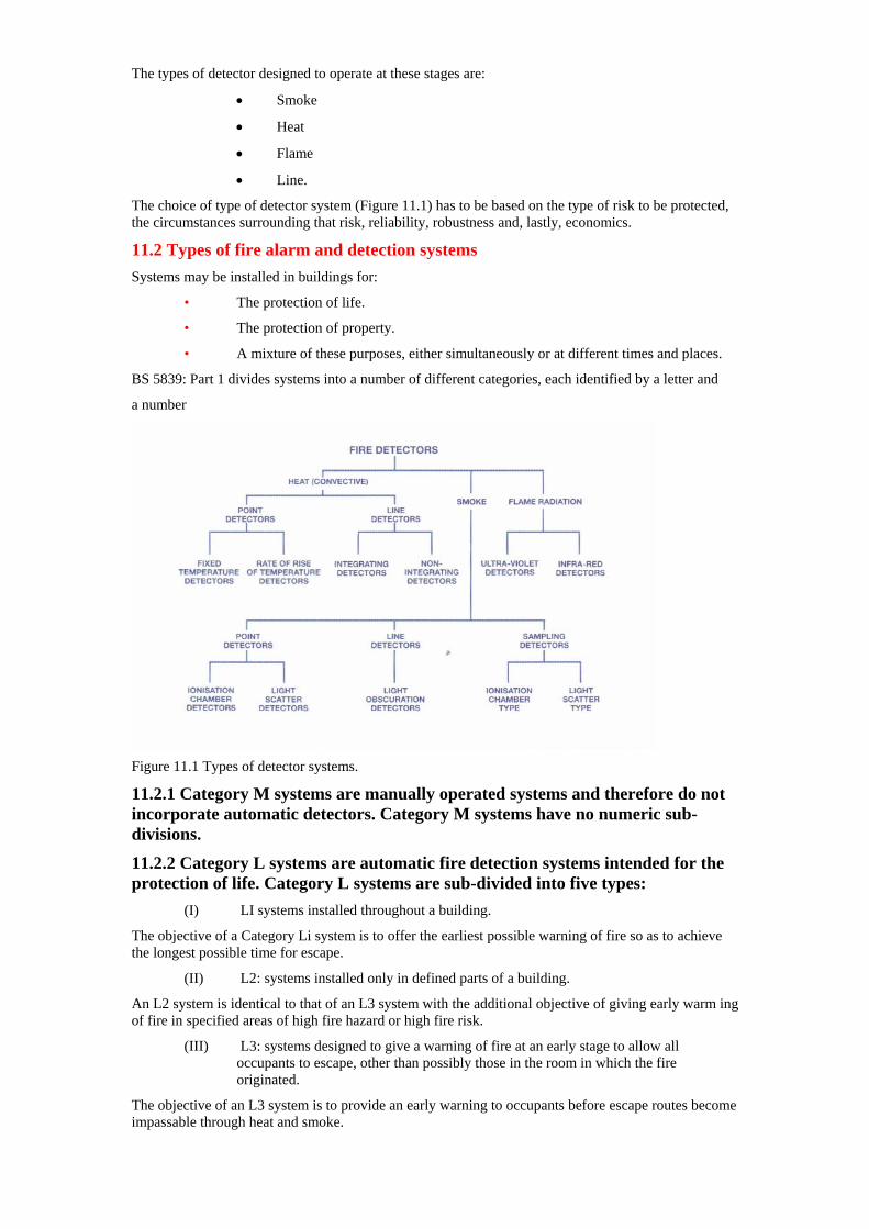
The types of detector designed to operate at these stages are:
• Smoke
• Heat
• Flame
• Line.
The choice of type of detector system (Figure 11.1) has to be based on the type of risk to be protected, the circumstances surrounding that risk, reliability, robustness and, lastly, economics.
11.2 Types of fire alarm and detection systems Systems may be installed in buildings for:
• The protection of life.
• The protection of property.
• A mixture of these purposes, either simultaneously or at different times and places.
BS 5839: Part 1 divides systems into a number of different categories, each identified by a letter and
a number
Figure 11.1 Types of detector systems.
11.2.1 Category M systems are manually operated systems and therefore do not incorporate automatic detectors. Category M systems have no numeric sub-divisions.
11.2.2 Category L systems are automatic fire detection systems intended for the protection of life. Category L systems are sub-divided into five types:
(I) LI systems installed throughout a building.
The objective of a Category Li system is to offer the earliest possible warning of fire so as to achieve the longest possible time for escape.
(II) L2: systems installed only in defined parts of a building.
An L2 system is identical to that of an L3 system with the additional objective of giving early warm ing of fire in specified areas of high fire hazard or high fire risk.
(III) L3: systems designed to give a warning of fire at an early stage to allow all occupants to escape, other than possibly those in the room in which the fire originated.
The objective of an L3 system is to provide an early warning to occupants before escape routes become impassable through heat and smoke.

(IV) L4: systems installed only within escape routes such as corridors and stairways and other circulation areas.
The objective of an L4 system is to enhance the safety of occupants by providing a warning of smoke on principal escape routes. Detectors may also be provided in other areas within the system category L4.
(V) L5: systems installed to satisfy a specific fire safety objective and which does not fall within any of the other categories.
The objective of category L5 is to offer a system based on fire risk assessment or to meet a fire safety engineering objective. Such a system could be used to compensate for a departure from a pre scribed structural or means of escape standard or where an outbreak of fire may otherwise put people at exceptional risk.
11.2.3 Category P systems are automatic fire detection systems designed for the protection of property. Category P systems are divided into two types.
(I) P1: systems installed throughout all areas of a building.
The objective of a Category P1 system is to offer the earliest possible warning of tire so as to minimise the time between ignition and the arrival of firefighters.
(II) P2: systems installed only in defined parts of buildings.
The objective of Category P2 systems is to provide early warning of fire in areas of high hazard or where the risk to business continuity from fire is high.
In all cases the systems should included manual call points to allow people in the vicinity of a fire to operate the system before it is detected automatically. Where systems are installed to meet mixed criteria, it should always be ensured that the installation meets requirements of each category, in particular meeting the higher criteria in the case of life risk.
11.3 Definition of a detector BS 5839: Part 1 states that a detector is:
‘A part of an automatic fire detection system that contains at least one sensor which constantly, or at frequent intervals, monitors at least one suitable physical and/or chemical phenomenon associated with fire. It provides at least one corresponding signal to the control and indicating equipment. The decision to give the alarm of fire, or to operate automatic fire protection equipment, may be made at the detector or at another part of the system, e.g. at the control and indicating equipment’.
11.4 Classification of detectors
11.4.1 Analogue detector A detector which is part of a system where the out put signal representing the value of the sensed fire phenomena is analysed, either at the detector or within the control equipment. The purpose of the analysis is to identify conditions that are not representative of fire, which may result in a false alarm from a ‘two state’ alarm system.
11.4.2 Two state detector A ‘two state’ fire detector is one which is only capable of indicating two output states, ‘normal’ and ‘fire’ conditions.
11.4.3 Multi state detector A multi state detector is one capable of indicating more than two output states, which include ‘normal’, ‘fire’ and other abnormal conditions. Multi state detectors are less likely to give false alarms of fire.
11.5 Success or failure of operation When a fire occurs in an area protected by an AFD, the probable sequence of events is as depicted in Figure 112. After ignition, the fire will grow, probably slowly and irregularly at first, but then at an accelerating rate.
Generally, products of the fire will be transported to the detector and they will be ‘checked’ against the prevailing environment. When the detection system is sufficiently ‘sure’ that what it is detect ing is not an ‘environmental fluctuation’ it will ‘decide’ that a fire exists and raise the alarm. All this appears straightforward but there are many ways in which an AFD system could fail. For example:
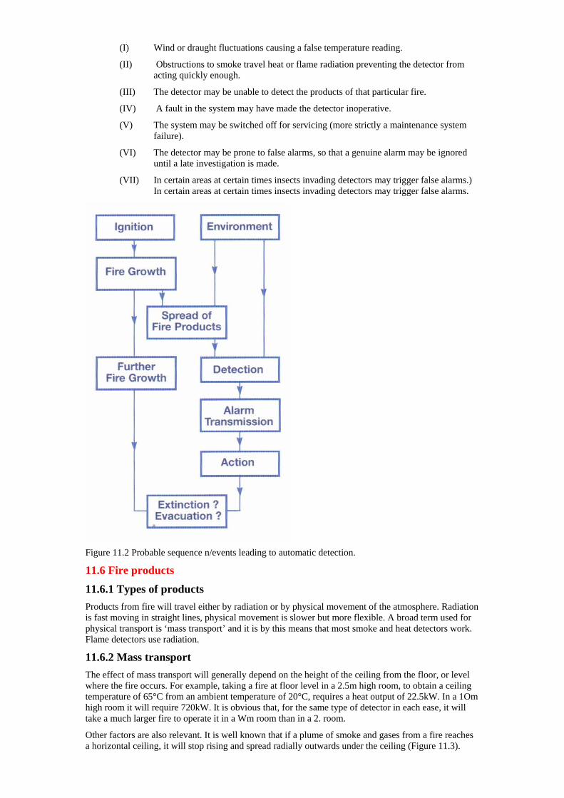
(I) Wind or draught fluctuations causing a false temperature reading.
(II) Obstructions to smoke travel heat or flame radiation preventing the detector from acting quickly enough.
(III) The detector may be unable to detect the products of that particular fire.
(IV) A fault in the system may have made the detector inoperative.
(V) The system may be switched off for servicing (more strictly a maintenance system failure).
(VI) The detector may be prone to false alarms, so that a genuine alarm may be ignored until a late investigation is made.
(VII) In certain areas at certain times insects invading detectors may trigger false alarms.) In certain areas at certain times insects invading detectors may trigger false alarms.
Figure 11.2 Probable sequence n/events leading to automatic detection.
11.6 Fire products
11.6.1 Types of products Products from fire will travel either by radiation or by physical movement of the atmosphere. Radiation is fast moving in straight lines, physical movement is slower but more flexible. A broad term used for physical transport is ‘mass transport’ and it is by this means that most smoke and heat detectors work. Flame detectors use radiation.
11.6.2 Mass transport The effect of mass transport will generally depend on the height of the ceiling from the floor, or level where the fire occurs. For example, taking a fire at floor level in a 2.5m high room, to obtain a ceiling temperature of 65°C from an ambient temperature of 20°C, requires a heat output of 22.5kW. In a 1Om high room it will require 720kW. It is obvious that, for the same type of detector in each ease, it will take a much larger fire to operate it in a Wm room than in a 2. room.
Other factors are also relevant. It is well known that if a plume of smoke and gases from a fire reaches a horizontal ceiling, it will stop rising and spread radially outwards under the ceiling (Figure 11.3).
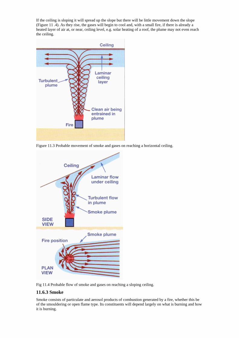
If the ceiling is sloping it will spread up the slope but there will be little movement down the slope (Figure 11 .4). As they rise, the gases will begin to cool and, with a small fire, if there is already a heated layer of air at, or near, ceiling level, e.g. solar heating of a roof, the plume may not even reach the ceiling.
Figure 11.3 Probable movement of smoke and gases on reaching a horizontal ceiling.
Fig 11.4 Probable flow of smoke and gases on reaching a sloping ceiling.
11.6.3 Smoke Smoke consists of particulate and aerosol products of combustion generated by a fire, whether this be of the smouldering or open flame type. Its constituents will depend largely on what is burning and how it is burning.
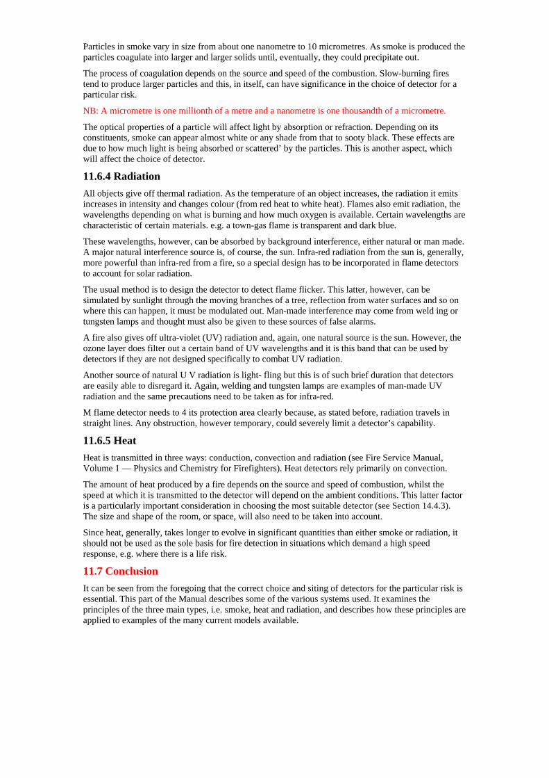
Particles in smoke vary in size from about one nanometre to 10 micrometres. As smoke is produced the particles coagulate into larger and larger solids until, eventually, they could precipitate out.
The process of coagulation depends on the source and speed of the combustion. Slow-burning fires tend to produce larger particles and this, in itself, can have significance in the choice of detector for a particular risk.
NB: A micrometre is one millionth of a metre and a nanometre is one thousandth of a micrometre.
The optical properties of a particle will affect light by absorption or refraction. Depending on its constituents, smoke can appear almost white or any shade from that to sooty black. These effects are due to how much light is being absorbed or scattered’ by the particles. This is another aspect, which will affect the choice of detector.
11.6.4 Radiation All objects give off thermal radiation. As the temperature of an object increases, the radiation it emits increases in intensity and changes colour (from red heat to white heat). Flames also emit radiation, the wavelengths depending on what is burning and how much oxygen is available. Certain wavelengths are characteristic of certain materials. e.g. a town-gas flame is transparent and dark blue.
These wavelengths, however, can be absorbed by background interference, either natural or man made. A major natural interference source is, of course, the sun. Infra-red radiation from the sun is, generally, more powerful than infra-red from a fire, so a special design has to be incorporated in flame detectors to account for solar radiation.
The usual method is to design the detector to detect flame flicker. This latter, however, can be simulated by sunlight through the moving branches of a tree, reflection from water surfaces and so on where this can happen, it must be modulated out. Man-made interference may come from weld ing or tungsten lamps and thought must also be given to these sources of false alarms.
A fire also gives off ultra-violet (UV) radiation and, again, one natural source is the sun. However, the ozone layer does filter out a certain band of UV wavelengths and it is this band that can be used by detectors if they are not designed specifically to combat UV radiation.
Another source of natural U V radiation is light- fling but this is of such brief duration that detectors are easily able to disregard it. Again, welding and tungsten lamps are examples of man-made UV radiation and the same precautions need to be taken as for infra-red.
M flame detector needs to 4 its protection area clearly because, as stated before, radiation travels in straight lines. Any obstruction, however temporary, could severely limit a detector’s capability.
11.6.5 Heat Heat is transmitted in three ways: conduction, convection and radiation (see Fire Service Manual, Volume 1 — Physics and Chemistry for Firefighters). Heat detectors rely primarily on convection.
The amount of heat produced by a fire depends on the source and speed of combustion, whilst the speed at which it is transmitted to the detector will depend on the ambient conditions. This latter factor is a particularly important consideration in choosing the most suitable detector (see Section 14.4.3). The size and shape of the room, or space, will also need to be taken into account.
Since heat, generally, takes longer to evolve in significant quantities than either smoke or radiation, it should not be used as the sole basis for fire detection in situations which demand a high speed response, e.g. where there is a life risk.
11.7 Conclusion It can be seen from the foregoing that the correct choice and siting of detectors for the particular risk is essential. This part of the Manual describes some of the various systems used. It examines the principles of the three main types, i.e. smoke, heat and radiation, and describes how these principles are applied to examples of the many current models available.
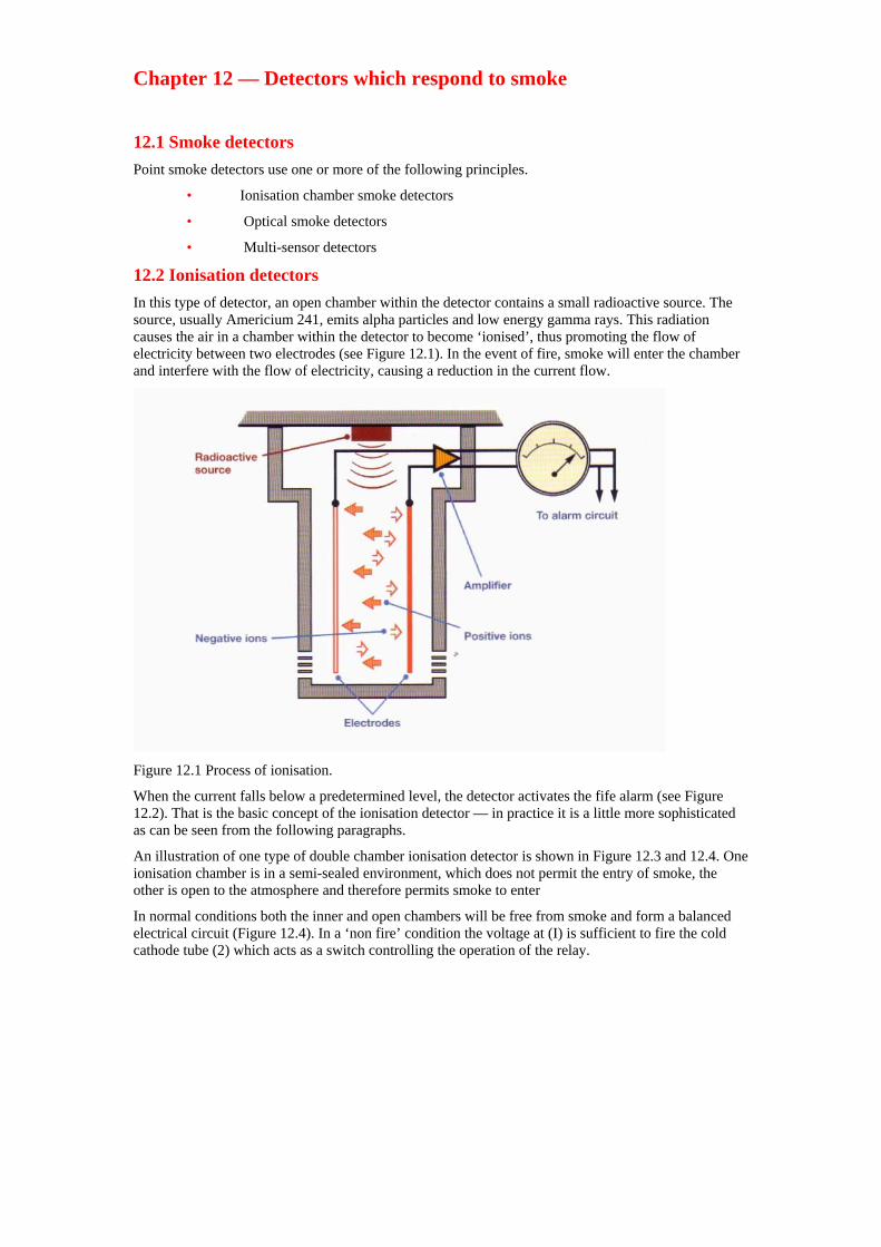
Chapter 12 — Detectors which respond to smoke 12.1 Smoke detectors Point smoke detectors use one or more of the following principles.
• Ionisation chamber smoke detectors
• Optical smoke detectors
• Multi-sensor detectors
12.2 Ionisation detectors In this type of detector, an open chamber within the detector contains a small radioactive source. The source, usually Americium 241, emits alpha particles and low energy gamma rays. This radiation causes the air in a chamber within the detector to become ‘ionised’, thus promoting the flow of electricity between two electrodes (see Figure 12.1). In the event of fire, smoke will enter the chamber and interfere with the flow of electricity, causing a reduction in the current flow.
Figure 12.1 Process of ionisation.
When the current falls below a predetermined level, the detector activates the fife alarm (see Figure 12.2). That is the basic concept of the ionisation detector — in practice it is a little more sophisticated as can be seen from the following paragraphs.
An illustration of one type of double chamber ionisation detector is shown in Figure 12.3 and 12.4. One ionisation chamber is in a semi-sealed environment, which does not permit the entry of smoke, the other is open to the atmosphere and therefore permits smoke to enter
In normal conditions both the inner and open chambers will be free from smoke and form a balanced electrical circuit (Figure 12.4). In a ‘non fire’ condition the voltage at (I) is sufficient to fire the cold cathode tube (2) which acts as a switch controlling the operation of the relay.
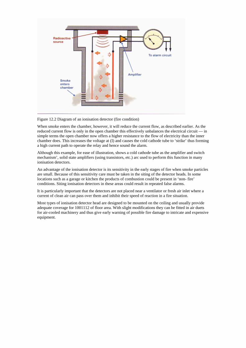
Figure 12.2 Diagram of an ionisation detector (fire condition)
When smoke enters the chamber, however, it will reduce the current flow, as described earlier. As the reduced current flow is only in the open chamber this effectively unbalances the electrical circuit — in simple terms the open chamber now offers a higher resistance to the flow of electricity than the inner chamber does. This increases the voltage at (I) and causes the cold cathode tube to ‘strike’ thus forming a high current path to operate the relay and hence sound the alarm.
Although this example, for ease of illustration, shows a cold cathode tube as the amplifier and switch mechanism’, solid state amplifiers (using transistors, etc.) arc used to perform this function in many ionisation detectors.
An advantage of the ionisation detector is its sensitivity in the early stages of fire when smoke particles are small. Because of this sensitivity care must be taken in the siting of the detector heads. In some locations such as a garage or kitchen the products of combustion could be present in ‘non- fire’ conditions. Siting ionisation detectors in these areas could result in repeated false alarms.
It is particularly important that the detectors are not placed near a ventilator or fresh air inlet where a current of clean air can pass over them and inhibit their speed of reaction in a fire situation.
Most types of ionisation detector head are designed to be mounted on the ceiling and usually provide adequate coverage for 1001112 of floor area. With slight modifications they can be fitted in air duets for air-cooled machinery and thus give early warning of possible fire damage to intricate and expensive equipment.
Figure 12.4 Diagram of one type of ionisation detector
Ionisation detectors with single chambers have been produced using a capacitor as a replacement for the second (inner) chamber. They have not been widely used however and the two-chamber type described above is the one most commonly found.
The radioactive source used in most ionisation type detectors, Americium 241, presents no danger to people even when damaged by fire.
12.3 Optical detectors While the ionisation detector responds to the invisible products of combustion the optical detector, as its name implies, reacts to the visible products of combustion, i.e. the particles of carbon and other chemicals which give smoke its characteristic appearance.
An optical detector has two important components, a light source and a photoelectric cell. It is the amount of light falling onto the photoelectric cell which is the critical factor in the operation of the optical detector. Some optical detectors are designed so that, in a fire situation, more light is thrown onto the photoelectric cell. These are called the ‘light-scatter type’. Others are designed so that less light is thrown onto the photoelectric cell in a fire situation. These are called ‘obscuration type’.
12.3.1 Light-scatter type
The light source and the photoelectric cell are mounted in a lightproof housing, which is designed to allow smoke to flow into it unimpeded. In the ‘non-fire’ condition light from the light source (usually a light emitting diode) does not fall on to the photoelectric cell. Figure 12.5 shows a light-scatter type in this condition.
When smoke particles enter the housing, however, some light is deflected upwards onto the photo electric cell. In response to the light falling onto it the cell will either create an electrical current in the detector circuit or allow more current to flow through it (depending on the type of cell being used).
The small increase in current is normally amplified by a transistorised circuit in order to energise a relay which controls the alarm. The detector is preset so that the alarm is given when the smoke density reaches a predetermined level (Figure 12.6).
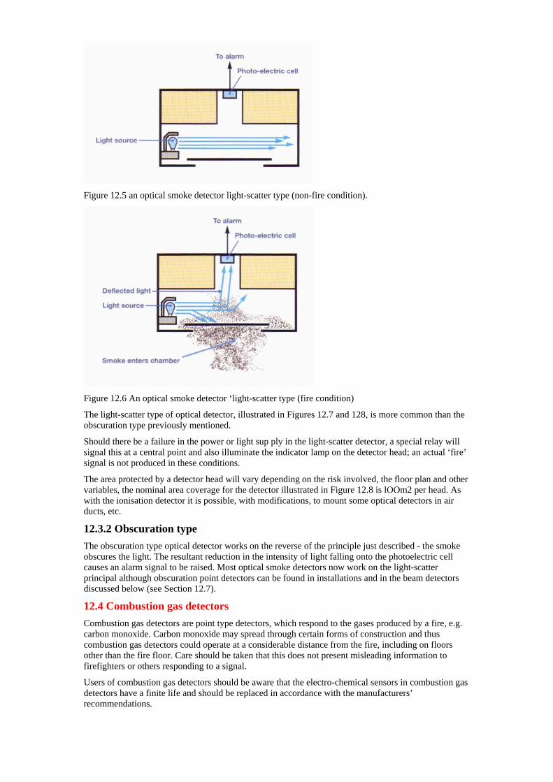
Figure 12.5 an optical smoke detector light-scatter type (non-fire condition).
Figure 12.6 An optical smoke detector ‘light-scatter type (fire condition)
The light-scatter type of optical detector, illustrated in Figures 12.7 and 128, is more common than the obscuration type previously mentioned.
Should there be a failure in the power or light sup ply in the light-scatter detector, a special relay will signal this at a central point and also illuminate the indicator lamp on the detector head; an actual ‘fire’ signal is not produced in these conditions.
The area protected by a detector head will vary depending on the risk involved, the floor plan and other variables, the nominal area coverage for the detector illustrated in Figure 12.8 is lOOm2 per head. As with the ionisation detector it is possible, with modifications, to mount some optical detectors in air ducts, etc.
12.3.2 Obscuration type The obscuration type optical detector works on the reverse of the principle just described - the smoke obscures the light. The resultant reduction in the intensity of light falling onto the photoelectric cell causes an alarm signal to be raised. Most optical smoke detectors now work on the light-scatter principal although obscuration point detectors can be found in installations and in the beam detectors discussed below (see Section 12.7).
12.4 Combustion gas detectors Combustion gas detectors are point type detectors, which respond to the gases produced by a fire, e.g. carbon monoxide. Carbon monoxide may spread through certain forms of construction and thus combustion gas detectors could operate at a considerable distance from the fire, including on floors other than the fire floor. Care should be taken that this does not present misleading information to firefighters or others responding to a signal.
Users of combustion gas detectors should be aware that the electro-chemical sensors in combustion gas detectors have a finite life and should be replaced in accordance with the manufacturers’ recommendations.
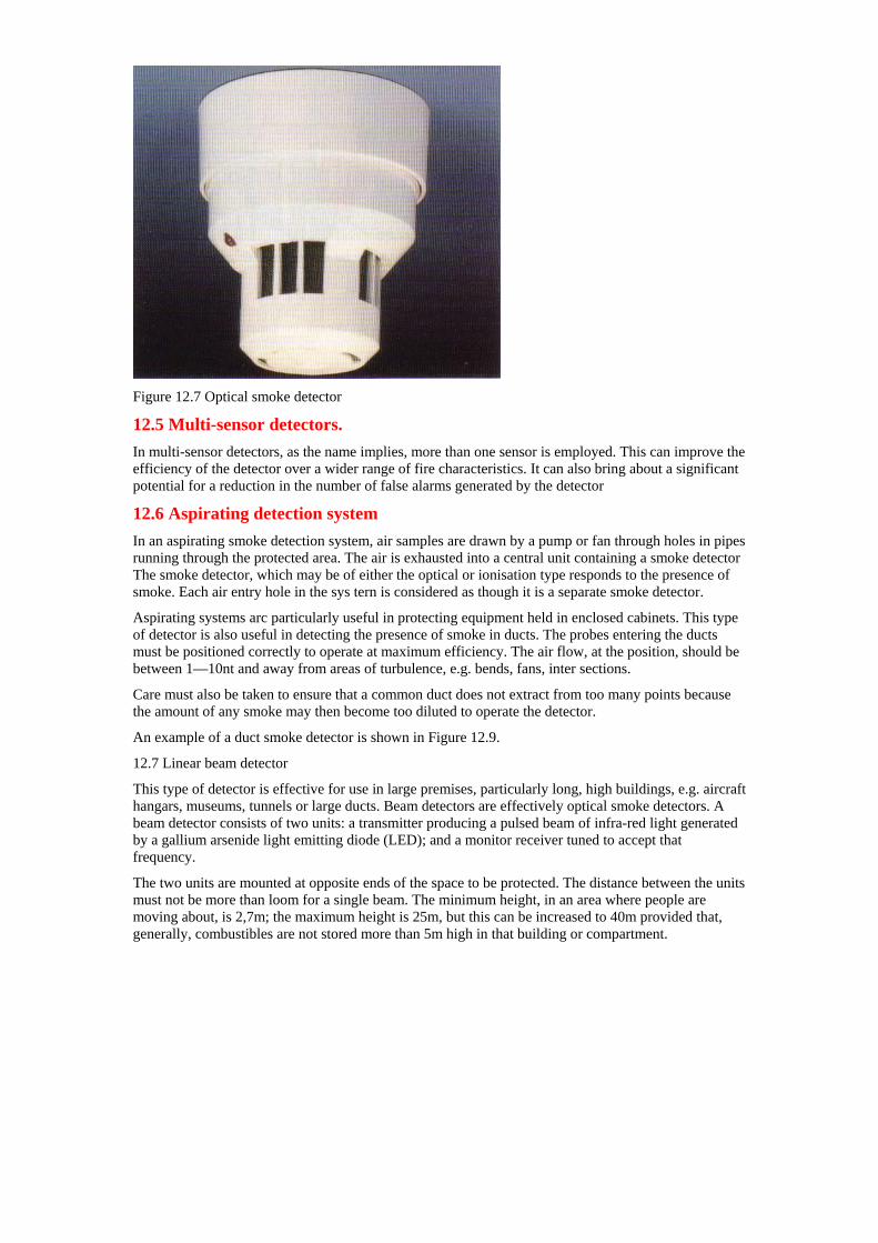
Figure 12.7 Optical smoke detector
12.5 Multi-sensor detectors. In multi-sensor detectors, as the name implies, more than one sensor is employed. This can improve the efficiency of the detector over a wider range of fire characteristics. It can also bring about a significant potential for a reduction in the number of false alarms generated by the detector
12.6 Aspirating detection system In an aspirating smoke detection system, air samples are drawn by a pump or fan through holes in pipes running through the protected area. The air is exhausted into a central unit containing a smoke detector The smoke detector, which may be of either the optical or ionisation type responds to the presence of smoke. Each air entry hole in the sys tern is considered as though it is a separate smoke detector.
Aspirating systems arc particularly useful in protecting equipment held in enclosed cabinets. This type of detector is also useful in detecting the presence of smoke in ducts. The probes entering the ducts must be positioned correctly to operate at maximum efficiency. The air flow, at the position, should be between 1—10nt and away from areas of turbulence, e.g. bends, fans, inter sections.
Care must also be taken to ensure that a common duct does not extract from too many points because the amount of any smoke may then become too diluted to operate the detector.
An example of a duct smoke detector is shown in Figure 12.9.
12.7 Linear beam detector
This type of detector is effective for use in large premises, particularly long, high buildings, e.g. aircraft hangars, museums, tunnels or large ducts. Beam detectors are effectively optical smoke detectors. A beam detector consists of two units: a transmitter producing a pulsed beam of infra-red light generated by a gallium arsenide light emitting diode (LED); and a monitor receiver tuned to accept that frequency.
The two units are mounted at opposite ends of the space to be protected. The distance between the units must not be more than loom for a single beam. The minimum height, in an area where people are moving about, is 2,7m; the maximum height is 25m, but this can be increased to 40m provided that, generally, combustibles are not stored more than 5m high in that building or compartment.
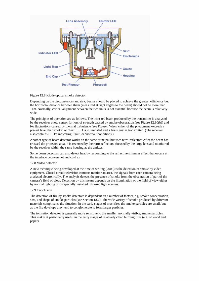
Figure 12.8 Kidde optical smoke detector
Depending on the circumstances and risk, beams should be placed to achieve the greatest efficiency but the horizontal distance between them (measured at right angles to the beam) should not be more than 14m. Normally, critical alignment between the two units is not essential because the beam is relatively wide.
The principles of operation are as follows. The infra-red beam produced by the transmitter is analysed by the receiver photo sensor for loss of strength caused by smoke obscuration (see Figure 12.10(b)) and for fluctuations caused by thermal turbulence (see Figure l When either of the phenomena exceeds a pre-set level the ‘smoke’ or ‘heat’ LED is illuminated and a fire signal is transmitted. (The receiver also contains LED’s indicating ‘fault’ or ‘normal’ conditions.)
Another type of beam detector works on the same principal but uses retro-reflectors After the beam has crossed the protected area, it is reversed by the retro-reflectors, focused by the large lens and monitored by the receiver within the same housing as the emitter.
Some beam detectors can also detect heat by responding to the refractive shimmer effect that occurs at the interface between hot and cold air.
12.8 Video detector
A new technique being developed at the time of writing (2003) is the detection of smoke by video equipment. Closed circuit television cameras monitor an area, the signals from each camera being analysed electronically. The analysis detects the presence of smoke from the obscuration of part of the camera’s field of view. Detection by this means depends on the illumination of the field of view either by normal lighting or by specially installed infra-red light sources.
12.9 Conclusion
The detection of fire by smoke detectors is dependent on a number of factors, e.g. smoke concentration, size, and shape of smoke particles (see Section 18.2). The wide variety of smoke produced by different materials complicates the situation. In the early stages of most fires the smoke particles are small, but as the fire develops they tend to conglomerate to form larger particles.
The ionisation detector is generally more sensitive to the smaller, normally visible, smoke particles. This makes it particularly useful in the early stages of relatively clean burning fires (e.g. of wood and paper).
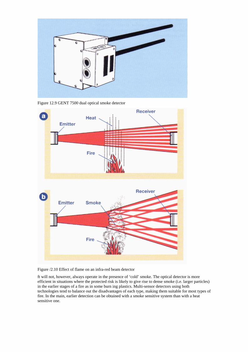
Figure 12.9 GENT 7500 dual optical smoke detector
Figure /2.10 Effect of flame on an infra-red beam detector
ft will not, however, always operate in the presence of ‘cold’ smoke. The optical detector is more efficient in situations where the protected risk is likely to give rise to dense smoke (i.e. larger particles) in the earlier stages of a fire as in some burn ing plastics. Multi-sensor detectors using both technologies tend to balance out the disadvantages of each type, making them suitable for most types of fire. In the main, earlier detection can be obtained with a smoke sensitive system than with a heat sensitive one.
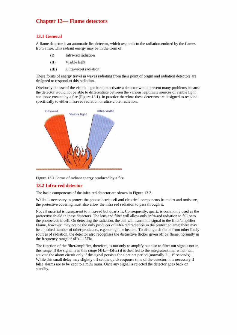
Chapter 13— Flame detectors
13.1 General A flame detector is an automatic fire detector, which responds to the radiation emitted by the flames from a fire. This radiant energy may be in the form of:
(I) Infra-red radiation
(II) Visible light
(III) Ultra-violet radiation.
These forms of energy travel in waves radiating from their point of origin and radiation detectors are designed to respond to this radiation.
Obviously the use of the visible light band to activate a detector would present many problems because the detector would not be able to differentiate between the various legitimate sources of visible light and those created by a fire (Figure 13.1). In practice therefore these detectors are designed to respond specifically to either infra-red radiation or ultra-violet radiation.
Figure 13.1 Forms of radiant energy produced by a fire
13.2 Infra-red detector The basic components of the infra-red detector arc shown in Figure 13.2.
Whilst is necessary to protect the photoelectric cell and electrical components from dirt and moisture, the protective covering must also allow the infra red radiation to pass through it.
Not all material is transparent to infra-red but quartz is. Consequently, quartz is commonly used as the protective shield in these detectors. The lens and filter will allow only infra-red radiation to fall onto the photoelectric cell. On detecting the radiation, the cell will transmit a signal to the filter/amplifier. Flame, however, may not be the only producer of infra-red radiation in the protect ed area; there may be a limited number of other producers, e.g. sunlight or heaters. To distinguish flame from other likely sources of radiation, the detector also recognises the distinctive flicker given off by flame, normally in the frequency range of 4Hz—l5Flz.
The function of the filter/amplifier, therefore, is not only to amplify but also to filter out signals not in this range. If the signal is in this range (4Hz—l5Hz) it is then fed to the integrator/timer which will activate the alarm circuit only if the signal persists for a pre-set period (normally 2—15 seconds). While this small delay may slightly off set the quick response time of the detector, it is necessary if false alarms are to be kept to a mini mum. Once any signal is rejected the detector goes back on standby.
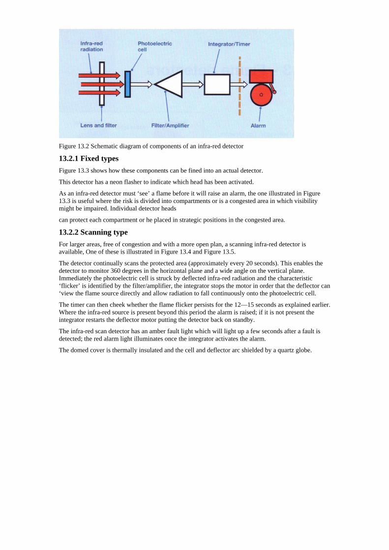
Figure 13.2 Schematic diagram of components of an infra-red detector
13.2.1 Fixed types Figure 13.3 shows how these components can be fined into an actual detector.
This detector has a neon flasher to indicate which head has been activated.
As an infra-red detector must ‘see’ a flame before it will raise an alarm, the one illustrated in Figure 13.3 is useful where the risk is divided into compartments or is a congested area in which visibility might be impaired. Individual detector heads
can protect each compartment or he placed in strategic positions in the congested area.
13.2.2 Scanning type For larger areas, free of congestion and with a more open plan, a scanning infra-red detector is available, One of these is illustrated in Figure 13.4 and Figure 13.5.
The detector continually scans the protected area (approximately every 20 seconds). This enables the detector to monitor 360 degrees in the horizontal plane and a wide angle on the vertical plane. Immediately the photoelectric cell is struck by deflected infra-red radiation and the characteristic ‘flicker’ is identified by the filter/amplifier, the integrator stops the motor in order that the deflector can ‘view the flame source directly and allow radiation to fall continuously onto the photoelectric cell.
The timer can then cheek whether the flame flicker persists for the 12—15 seconds as explained earlier. Where the infra-red source is present beyond this period the alarm is raised; if it is not present the integrator restarts the deflector motor putting the detector back on standby.
The infra-red scan detector has an amber fault light which will light up a few seconds after a fault is detected; the red alarm light illuminates once the integrator activates the alarm.
The domed cover is thermally insulated and the cell and deflector arc shielded by a quartz globe.
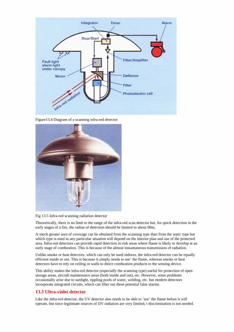
Figure13.4 Diagram of a scanning infra-red detector
Fig 13.5 Infra-red scanning radiation detector
Theoretically, there is no limit to the range of the infra-red scan detector but, for quick detection in the early stages of a fire, the radius of detection should be limited to about 90m,
A much greater area of coverage can be obtained from the scanning type than from the static type but which type is used in any particular situation will depend on the interior plan and use of the protected area. Infra-red detectors can provide rapid detection in risk areas where flame is likely to develop at an early stage of combustion. This is because of the almost instantaneous transmission of radiation.
Unlike smoke or heat detectors, which can only be used indoors, the infra-red detector can be equally efficient inside or out. This is because it simply needs to see’ the flame, whereas smoke or heat detectors have to rely on ceiling or walls to direct combustion products to the sensing device.
This ability makes the infra-red detector (especially the scanning type) useful for protection of open storage areas, aircraft maintenance areas (both inside and out), etc. However, some problems occasionally arise due to sunlight, rippling pools of water, welding, etc. but modern detectors incorporate integrated circuits, which can filter out these potential false alarms.
13.3 Ultra-violet detector Like the infra-red detector, the UV detector also needs to be able to ‘see’ the flame before it will operate, but since legitimate sources of IJV radiation are very limited, t discrimination is not needed.
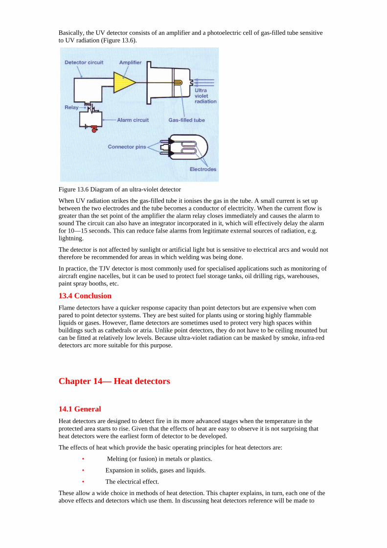
Basically, the UV detector consists of an amplifier and a photoelectric cell of gas-filled tube sensitive to UV radiation (Figure 13.6).
Figure 13.6 Diagram of an ultra-violet detector
When UV radiation strikes the gas-filled tube it ionises the gas in the tube. A small current is set up between the two electrodes and the tube becomes a conductor of electricity. When the current flow is greater than the set point of the amplifier the alarm relay closes immediately and causes the alarm to sound The circuit can also have an integrator incorporated in it, which will effectively delay the alarm for 10—15 seconds. This can reduce false alarms from legitimate external sources of radiation, e.g. lightning.
The detector is not affected by sunlight or artificial light but is sensitive to electrical arcs and would not therefore be recommended for areas in which welding was being done.
In practice, the TJV detector is most commonly used for specialised applications such as monitoring of aircraft engine nacelles, but it can be used to protect fuel storage tanks, oil drilling rigs, warehouses, paint spray booths, etc.
13.4 Conclusion Flame detectors have a quicker response capacity than point detectors but are expensive when com pared to point detector systems. They are best suited for plants using or storing highly flammable liquids or gases. However, flame detectors are sometimes used to protect very high spaces within buildings such as cathedrals or atria. Unlike point detectors, they do not have to be ceiling mounted but can be fitted at relatively low levels. Because ultra-violet radiation can be masked by smoke, infra-red detectors arc more suitable for this purpose.
Chapter 14— Heat detectors 14.1 General Heat detectors are designed to detect fire in its more advanced stages when the temperature in the protected area starts to rise. Given that the effects of heat are easy to observe it is not surprising that heat detectors were the earliest form of detector to be developed.
The effects of heat which provide the basic operating principles for heat detectors are:
• Melting (or fusion) in metals or plastics.
• Expansion in solids, gases and liquids.
• The electrical effect.
These allow a wide choice in methods of heat detection. This chapter explains, in turn, each one of the above effects and detectors which use them. In discussing heat detectors reference will be made to
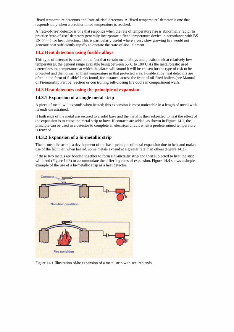
‘fixed temperature detectors and ‘rate-of-rise’ detectors. A ‘fixed temperature’ detector is one that responds only when a predetermined temperature is reached.
A ‘rate-of-rise’ detector is one that responds when the rate of temperature rise is abnormally rapid. In practice ‘rate-of-rise’ detectors generally incorporate a fixed temperature device in accordance with BS EN 54—5 for heat detectors. This is particularly useful where a very slow growing fire would not generate heat sufficiently rapidly to operate the ‘rate-of-rise’ element.
14.2 Heat detectors using fusible alloys This type of detector is based on the fact that certain metal alloys and plastics melt at relatively low temperatures, the general range available being between 55°C to 180ºC As the metal/plastic used determines the temperature at which the alarm will sound it will be chosen for the type of risk to be protected and the normal ambient temperature in that protected area. Fusible alloy heat detectors are often in the form of fusible’ links found, for instance, across the front of oil-fired boilers (see Manual of Firemanship Part be, Section or con trolling self-closing fire doors in compartment walls.
14.3 Heat detectors using the principle of expansion
14.3.1 Expansion of a single metal strip A piece of metal will expand! when heated; this expansion is most noticeable in a length of metal with its ends unrestrained.
If both ends of the metal are secured to a solid base and the metal is then subjected to heat the effect of the expansion is to cause the metal strip to bow. If contacts are added, as shown in Figure 14.1, the principle can be used in a detector to complete an electrical circuit when a predetermined temperature is reached.
14.3.2 Expansion of a hi-metallic strip The bi-metallic strip is a development of the basic principle of metal expansion due to heat and makes use of the fact that, when heated, some metals expand at a greater rate than others (Figure 14.2).
if these two metals are bonded together to form a hi-metallic strip and then subjected to heat the strip will bend (Figure 14.3) to accommodate the differ ing rates of expansion. Figure 14.4 shows a simple example of the use of a hi-metallic strip as a heat detector.
Figure 14.1 Illustration of/he expansion of a metal strip with secured ends
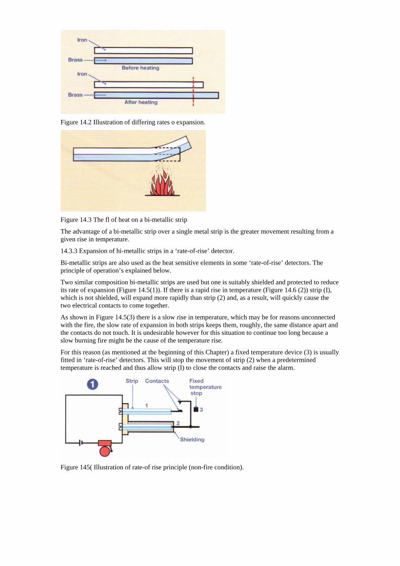
Figure 14.2 Illustration of differing rates o expansion.
Figure 14.3 The fl of heat on a bi-metallic strip
The advantage of a bi-metallic strip over a single metal strip is the greater movement resulting from a given rise in temperature.
14.3.3 Expansion of hi-metallic strips in a ‘rate-of-rise’ detector.
Bi-metallic strips are also used as the heat sensitive elements in some ‘rate-of-rise’ detectors. The principle of operation’s explained below.
Two similar composition bi-metallic strips are used but one is suitably shielded and protected to reduce its rate of expansion (Figure 14.5(1)). If there is a rapid rise in temperature (Figure 14.6 (2)) strip (I), which is not shielded, will expand more rapidly than strip (2) and, as a result, will quickly cause the two electrical contacts to come together.
As shown in Figure 14.5(3) there is a slow rise in temperature, which may be for reasons unconnected with the fire, the slow rate of expansion in both strips keeps them, roughly, the same distance apart and the contacts do not touch. It is undesirable however for this situation to continue too long because a slow burning fire might be the cause of the temperature rise.
For this reason (as mentioned at the beginning of this Chapter) a fixed temperature device (3) is usually fitted in ‘rate-of-rise’ detectors. This will stop the movement of strip (2) when a predetermined temperature is reached and thus allow strip (I) to close the contacts and raise the alarm.
Figure 145( Illustration of rate-of rise principle (non-fire condition).
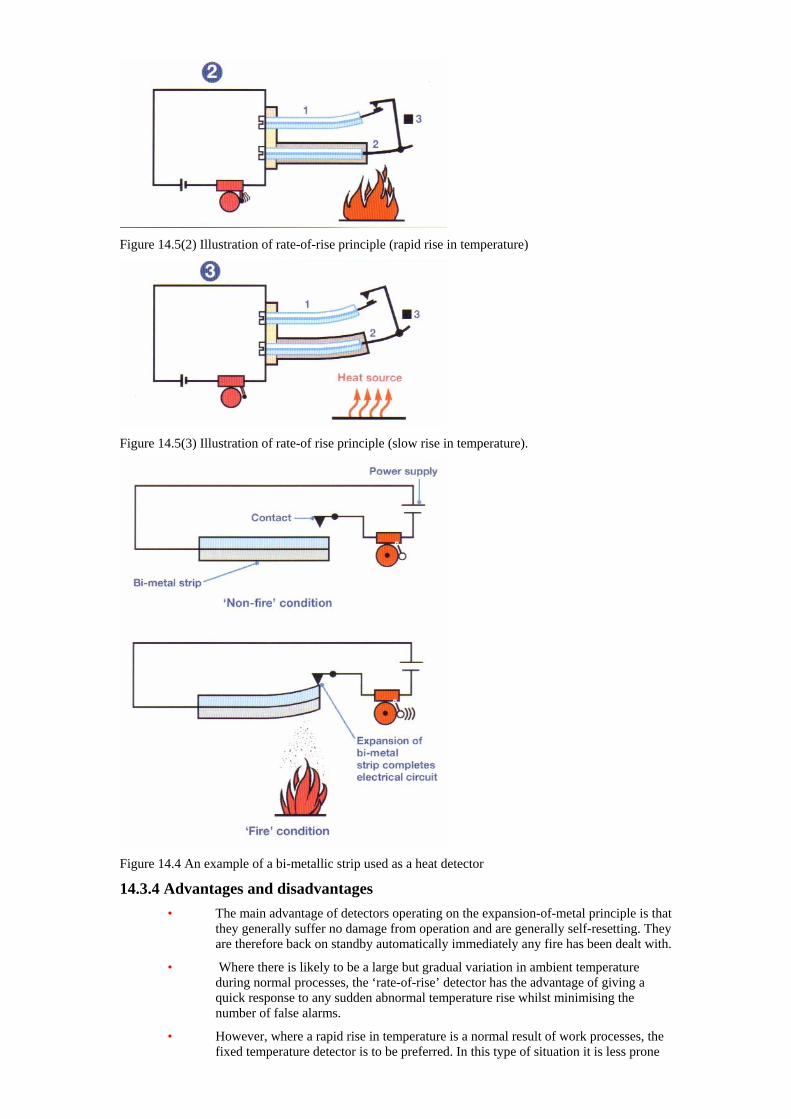
Figure 14.5(2) Illustration of rate-of-rise principle (rapid rise in temperature)
Figure 14.5(3) Illustration of rate-of rise principle (slow rise in temperature).
Figure 14.4 An example of a bi-metallic strip used as a heat detector
14.3.4 Advantages and disadvantages • The main advantage of detectors operating on the expansion-of-metal principle is that
they generally suffer no damage from operation and are generally self-resetting. They are therefore back on standby automatically immediately any fire has been dealt with.
• Where there is likely to be a large but gradual variation in ambient temperature during normal processes, the ‘rate-of-rise’ detector has the advantage of giving a quick response to any sudden abnormal temperature rise whilst minimising the number of false alarms.
• However, where a rapid rise in temperature is a normal result of work processes, the fixed temperature detector is to be preferred. In this type of situation it is less prone
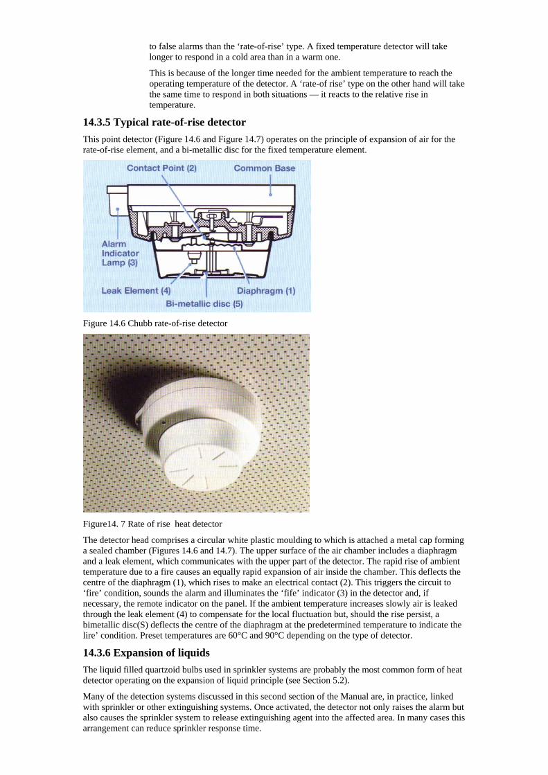
to false alarms than the ‘rate-of-rise’ type. A fixed temperature detector will take longer to respond in a cold area than in a warm one.
This is because of the longer time needed for the ambient temperature to reach the operating temperature of the detector. A ‘rate-of rise’ type on the other hand will take the same time to respond in both situations — it reacts to the relative rise in temperature.
14.3.5 Typical rate-of-rise detector This point detector (Figure 14.6 and Figure 14.7) operates on the principle of expansion of air for the rate-of-rise element, and a bi-metallic disc for the fixed temperature element.
Figure 14.6 Chubb rate-of-rise detector
Figure14. 7 Rate of rise heat detector
The detector head comprises a circular white plastic moulding to which is attached a metal cap forming a sealed chamber (Figures 14.6 and 14.7). The upper surface of the air chamber includes a diaphragm and a leak element, which communicates with the upper part of the detector. The rapid rise of ambient temperature due to a fire causes an equally rapid expansion of air inside the chamber. This deflects the centre of the diaphragm (1), which rises to make an electrical contact (2). This triggers the circuit to ‘fire’ condition, sounds the alarm and illuminates the ‘fife’ indicator (3) in the detector and, if necessary, the remote indicator on the panel. If the ambient temperature increases slowly air is leaked through the leak element (4) to compensate for the local fluctuation but, should the rise persist, a bimetallic disc(S) deflects the centre of the diaphragm at the predetermined temperature to indicate the lire’ condition. Preset temperatures are 60°C and 90°C depending on the type of detector.
14.3.6 Expansion of liquids The liquid filled quartzoid bulbs used in sprinkler systems are probably the most common form of heat detector operating on the expansion of liquid principle (see Section 5.2).
Many of the detection systems discussed in this second section of the Manual are, in practice, linked with sprinkler or other extinguishing systems. Once activated, the detector not only raises the alarm but also causes the sprinkler system to release extinguishing agent into the affected area. In many cases this arrangement can reduce sprinkler response time.
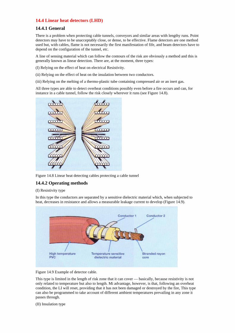
14.4 Linear heat detectors (LHD)
14.4.1 General There is a problem when protecting cable tunnels, conveyors and similar areas with lengthy runs. Point detectors may have to be unacceptably close, or dense, to be effective. Flame detectors are one method used but, with cables, flame is not necessarily the first manifestation of fife, and beam detectors have to depend on the configuration of the tunnel, etc.
A line of sensing material which can follow the contours of the risk are obviously a method and this is generally known as linear detection. There are, at the moment, three types:
(I) Relying on the effect of heat on electrical Resistivity.
(ii) Relying on the effect of heat on the insulation between two conductors.
(iii) Relying on the melting of a thermo-plastic tube containing compressed air or an inert gas.
All three types are able to detect overheat conditions possibly even before a fire occurs and can, for instance in a cable tunnel, follow the risk closely wherever it runs (see Figure 14.8).
Figure 14.8 Linear heat detecting cables protecting a cable tunnel
14.4.2 Operating methods (I) Resistivity type
In this type the conductors are separated by a sensitive dielectric material which, when subjected to heat, decreases in resistance and allows a measurable leakage current to develop (Figure 14.9).
Figure 14.9 Example of detector cable.
This type is limited in the length of risk zone that it can cover — basically, because resistivity is not only related to temperature but also to length. Mi advantage, however, is that, following an overheat condition, the LI will reset, providing that it has not been damaged or destroyed by the fire, This type can also be programmed to take account of different ambient temperatures prevailing in any zone it passes through.
(II) Insulation type
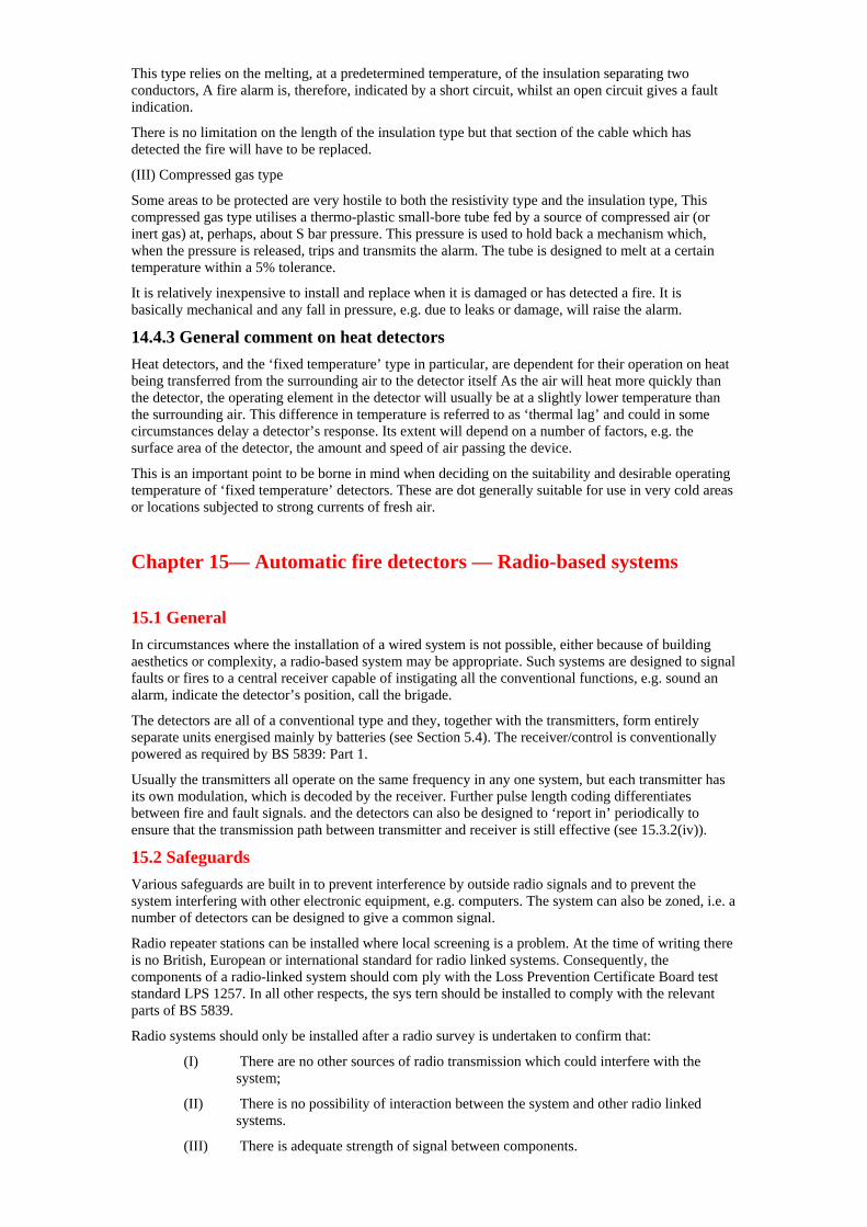
This type relies on the melting, at a predetermined temperature, of the insulation separating two conductors, A fire alarm is, therefore, indicated by a short circuit, whilst an open circuit gives a fault indication.
There is no limitation on the length of the insulation type but that section of the cable which has detected the fire will have to be replaced.
(III) Compressed gas type
Some areas to be protected are very hostile to both the resistivity type and the insulation type, This compressed gas type utilises a thermo-plastic small-bore tube fed by a source of compressed air (or inert gas) at, perhaps, about S bar pressure. This pressure is used to hold back a mechanism which, when the pressure is released, trips and transmits the alarm. The tube is designed to melt at a certain temperature within a 5% tolerance.
It is relatively inexpensive to install and replace when it is damaged or has detected a fire. It is basically mechanical and any fall in pressure, e.g. due to leaks or damage, will raise the alarm.
14.4.3 General comment on heat detectors Heat detectors, and the ‘fixed temperature’ type in particular, are dependent for their operation on heat being transferred from the surrounding air to the detector itself As the air will heat more quickly than the detector, the operating element in the detector will usually be at a slightly lower temperature than the surrounding air. This difference in temperature is referred to as ‘thermal lag’ and could in some circumstances delay a detector’s response. Its extent will depend on a number of factors, e.g. the surface area of the detector, the amount and speed of air passing the device.
This is an important point to be borne in mind when deciding on the suitability and desirable operating temperature of ‘fixed temperature’ detectors. These are dot generally suitable for use in very cold areas or locations subjected to strong currents of fresh air.
Chapter 15— Automatic fire detectors — Radio-based systems
15.1 General In circumstances where the installation of a wired system is not possible, either because of building aesthetics or complexity, a radio-based system may be appropriate. Such systems are designed to signal faults or fires to a central receiver capable of instigating all the conventional functions, e.g. sound an alarm, indicate the detector’s position, call the brigade.
The detectors are all of a conventional type and they, together with the transmitters, form entirely separate units energised mainly by batteries (see Section 5.4). The receiver/control is conventionally powered as required by BS 5839: Part 1.
Usually the transmitters all operate on the same frequency in any one system, but each transmitter has its own modulation, which is decoded by the receiver. Further pulse length coding differentiates between fire and fault signals. and the detectors can also be designed to ‘report in’ periodically to ensure that the transmission path between transmitter and receiver is still effective (see 15.3.2(iv)).
15.2 Safeguards Various safeguards are built in to prevent interference by outside radio signals and to prevent the system interfering with other electronic equipment, e.g. computers. The system can also be zoned, i.e. a number of detectors can be designed to give a common signal.
Radio repeater stations can be installed where local screening is a problem. At the time of writing there is no British, European or international standard for radio linked systems. Consequently, the components of a radio-linked system should com ply with the Loss Prevention Certificate Board test standard LPS 1257. In all other respects, the sys tern should be installed to comply with the relevant parts of BS 5839.
Radio systems should only be installed after a radio survey is undertaken to confirm that:
(I) There are no other sources of radio transmission which could interfere with the system;
(II) There is no possibility of interaction between the system and other radio linked systems.
(III) There is adequate strength of signal between components.
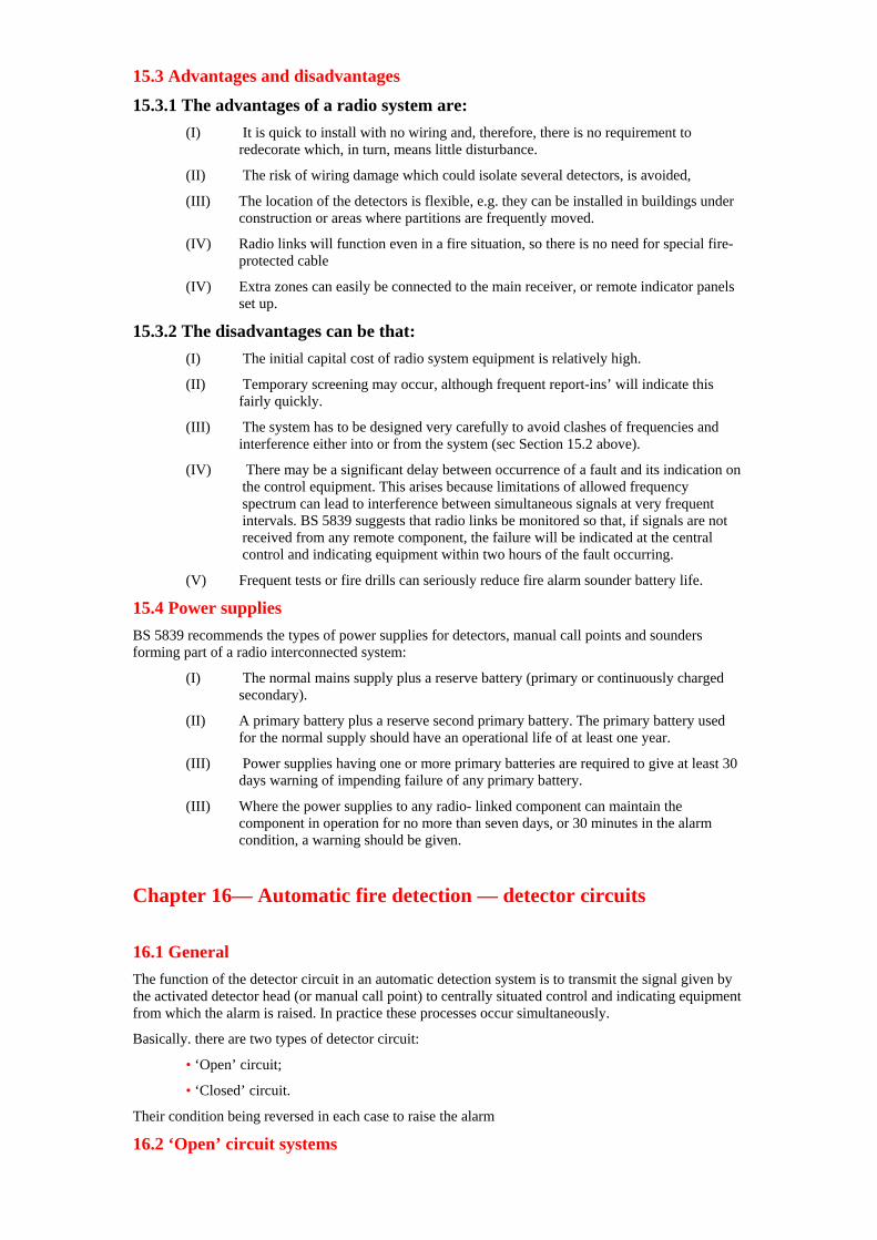
15.3 Advantages and disadvantages
15.3.1 The advantages of a radio system are: (I) It is quick to install with no wiring and, therefore, there is no requirement to
redecorate which, in turn, means little disturbance.
(II) The risk of wiring damage which could isolate several detectors, is avoided,
(III) The location of the detectors is flexible, e.g. they can be installed in buildings under construction or areas where partitions are frequently moved.
(IV) Radio links will function even in a fire situation, so there is no need for special fire-protected cable
(IV) Extra zones can easily be connected to the main receiver, or remote indicator panels set up.
15.3.2 The disadvantages can be that: (I) The initial capital cost of radio system equipment is relatively high.
(II) Temporary screening may occur, although frequent report-ins’ will indicate this fairly quickly.
(III) The system has to be designed very carefully to avoid clashes of frequencies and interference either into or from the system (sec Section 15.2 above).
(IV) There may be a significant delay between occurrence of a fault and its indication on the control equipment. This arises because limitations of allowed frequency spectrum can lead to interference between simultaneous signals at very frequent intervals. BS 5839 suggests that radio links be monitored so that, if signals are not received from any remote component, the failure will be indicated at the central control and indicating equipment within two hours of the fault occurring.
(V) Frequent tests or fire drills can seriously reduce fire alarm sounder battery life.
15.4 Power supplies BS 5839 recommends the types of power supplies for detectors, manual call points and sounders forming part of a radio interconnected system:
(I) The normal mains supply plus a reserve battery (primary or continuously charged secondary).
(II) A primary battery plus a reserve second primary battery. The primary battery used for the normal supply should have an operational life of at least one year.
(III) Power supplies having one or more primary batteries are required to give at least 30 days warning of impending failure of any primary battery.
(III) Where the power supplies to any radio- linked component can maintain the component in operation for no more than seven days, or 30 minutes in the alarm condition, a warning should be given.
Chapter 16— Automatic fire detection — detector circuits
16.1 General The function of the detector circuit in an automatic detection system is to transmit the signal given by the activated detector head (or manual call point) to centrally situated control and indicating equipment from which the alarm is raised. In practice these processes occur simultaneously.
Basically. there are two types of detector circuit:
• ‘Open’ circuit;
• ‘Closed’ circuit.
Their condition being reversed in each case to raise the alarm
16.2 ‘Open’ circuit systems
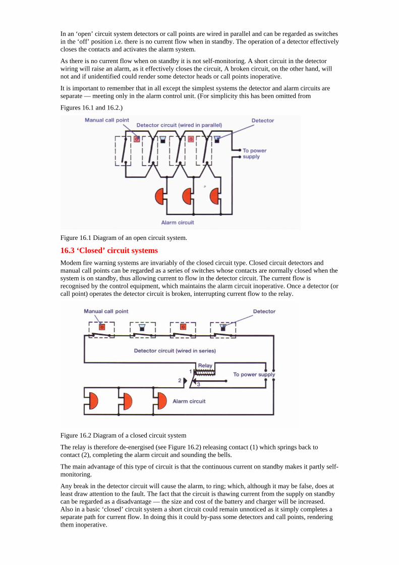
In an ‘open’ circuit system detectors or call points are wired in parallel and can be regarded as switches in the ‘off’ position i.e. there is no current flow when in standby. The operation of a detector effectively closes the contacts and activates the alarm system.
As there is no current flow when on standby it is not self-monitoring. A short circuit in the detector wiring will raise an alarm, as it effectively closes the circuit, A broken circuit, on the other hand, will not and if unidentified could render some detector heads or call points inoperative.
It is important to remember that in all except the simplest systems the detector and alarm circuits are separate — meeting only in the alarm control unit. (For simplicity this has been omitted from
Figures 16.1 and 16.2.)
Figure 16.1 Diagram of an open circuit system.
16.3 ‘Closed’ circuit systems Modem fire warning systems are invariably of the closed circuit type. Closed circuit detectors and manual call points can be regarded as a series of switches whose contacts are normally closed when the system is on standby, thus allowing current to flow in the detector circuit. The current flow is recognised by the control equipment, which maintains the alarm circuit inoperative. Once a detector (or call point) operates the detector circuit is broken, interrupting current flow to the relay.
Figure 16.2 Diagram of a closed circuit system
The relay is therefore de-energised (see Figure 16.2) releasing contact (1) which springs back to contact (2), completing the alarm circuit and sounding the bells.
The main advantage of this type of circuit is that the continuous current on standby makes it partly self-monitoring.
Any break in the detector circuit will cause the alarm, to ring; which, although it may be false, does at least draw attention to the fault. The fact that the circuit is thawing current from the supply on standby can be regarded as a disadvantage — the size and cost of the battery and charger will be increased. Also in a basic ‘closed’ circuit system a short circuit could remain unnoticed as it simply completes a separate path for current flow. In doing this it could by-pass some detectors and call points, rendering them inoperative.
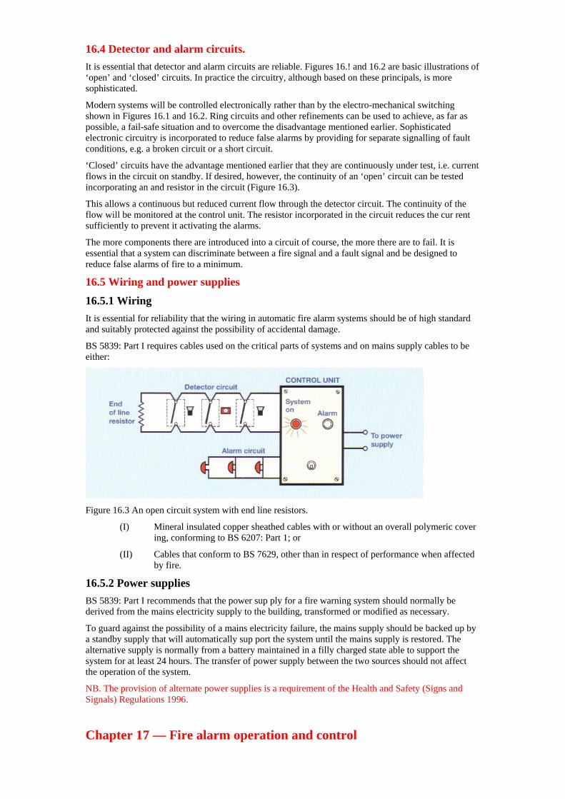
16.4 Detector and alarm circuits. It is essential that detector and alarm circuits are reliable. Figures 16.! and 16.2 are basic illustrations of ‘open’ and ‘closed’ circuits. In practice the circuitry, although based on these principals, is more sophisticated.
Modern systems will be controlled electronically rather than by the electro-mechanical switching shown in Figures 16.1 and 16.2. Ring circuits and other refinements can be used to achieve, as far as possible, a fail-safe situation and to overcome the disadvantage mentioned earlier. Sophisticated electronic circuitry is incorporated to reduce false alarms by providing for separate signalling of fault conditions, e.g. a broken circuit or a short circuit.
‘Closed’ circuits have the advantage mentioned earlier that they are continuously under test, i.e. current flows in the circuit on standby. If desired, however, the continuity of an ‘open’ circuit can be tested incorporating an and resistor in the circuit (Figure 16.3).
This allows a continuous but reduced current flow through the detector circuit. The continuity of the flow will be monitored at the control unit. The resistor incorporated in the circuit reduces the cur rent sufficiently to prevent it activating the alarms.
The more components there are introduced into a circuit of course, the more there are to fail. It is essential that a system can discriminate between a fire signal and a fault signal and be designed to reduce false alarms of fire to a minimum.
16.5 Wiring and power supplies
16.5.1 Wiring It is essential for reliability that the wiring in automatic fire alarm systems should be of high standard and suitably protected against the possibility of accidental damage.
BS 5839: Part I requires cables used on the critical parts of systems and on mains supply cables to be either:
Figure 16.3 An open circuit system with end line resistors.
(I) Mineral insulated copper sheathed cables with or without an overall polymeric cover ing, conforming to BS 6207: Part 1; or
(II) Cables that conform to BS 7629, other than in respect of performance when affected by fire.
16.5.2 Power supplies BS 5839: Part I recommends that the power sup ply for a fire warning system should normally be derived from the mains electricity supply to the building, transformed or modified as necessary.
To guard against the possibility of a mains electricity failure, the mains supply should be backed up by a standby supply that will automatically sup port the system until the mains supply is restored. The alternative supply is normally from a battery maintained in a filly charged state able to support the system for at least 24 hours. The transfer of power supply between the two sources should not affect the operation of the system.
NB. The provision of alternate power supplies is a requirement of the Health and Safety (Signs and Signals) Regulations 1996.
Chapter 17 — Fire alarm operation and control
17.1 General Fire alarm systems are essential if people are to evacuate a building successfully at the time of a fire. Often the evacuation process is simple where all people leave the building when the alarm sounds. However, in some larger buildings a two- stage or phased evacuation may be desirable per haps to maintain an essential service. In sonic buildings, the means of escape arrangements are designed to cope with a flow of people, phased to evacuate the building in a predetermined sequence rather than in one mass. The control of both two- stage and phased evacuation is through the fire alarm system on a zoned basis.
17.2 Zones In larger buildings, the fire detection and alarm system may be divided into zones. These are:
• Detection zones
• Alarm zones
17.2.1 Detection zones In most larger fire alarm systems, particularly automatic systems, the detectors and manual call points will be based on zones within the protected premises. This enables the indicator boards to show more precisely the whereabouts of the origin of the signal.
Depending on the sophistication of the system, this signal could be a visual and audible indication plus, possibly, a logging printout of the exact location of the actuated device within the zone. Simpler systems will just indicate the zone as an illuminated sign of a certain colour denoting the states of the signal plus an audible signal.
Detection zone indication will help direct fire fighters to the area of the fire. This is particularly the case where the system is automatic. In the case of a Category M system (see Section 11.2.1), where only manual call points are provided, a per son might operate a point some distance from the fire. The advantages of zoning in those cases may be less significant.
BS 5839: Part I makes certain recommendations for the size and configuration of zones:
(I) Where manual call points are provided on landings, the call point should be incorporated in the zone served by that landing.
(II) If the total floor area of the building exceeds 300m zones should be restricted to a single storey. If the total floor area of the building is 300m or less, the building may be considered a single zone even though there may be more than one storey.
(III) The floor area of a single zone should not exceed 2,000m except in a single storey open plan area (e.g. warehouse) where the zone should not be more than I O,000m
(IV) Where a zone is served by non-addressable detectors, the ‘search distance’, i.e. the distance that may have to be travelled by a per son responding to a fire alarm signal seeking to locate the fire visually should not exceed 60m.
Note: A person need not reach the seat of the fire, only travel sufficient distance to make visual contact with it. This requirement does not apply where the zone is served by addressable detectors.
(V) Where the zone is served by addressable detectors, the control equipment should automatically give a visual indication of the zone affected together with a text display of the location of the first detector to respond to the fire. This display should be supported by other information, e.g. a building floor plan, to enable firefighters who maybe unfamiliar with the building to proceed directly to the location of the fire.
(VI) Automatic detectors in an enclosed stairwell, lift well or other flue like structure are considered as a separate zone.
17.2.2 Alarm zones In buildings with simple evacuation strategies, the actuation of a call point or detector will cause the alarm system throughout the building to operate. In larger buildings the means of escape arrangements may be designed around more sophisticated evacuation process. That may be:
• Staged evacuation
• Phased evacuation
• Progressive horizontal evacuation.
In staged evacuation, the ‘evacuation’ signal is given in the zones where people might be at greatest risk, e.g. the fire zone and those immediately above or adjacent to it. In all other zones, an ‘alert’ signal is given which may be converted to an evacuation signal if the situation demands it.
Phased evacuation is a more complex process where people are evacuated in a predetermined sequence according to the degree of risk they may be in from a fire. Instructions to people in the building at the time of a fire are normally by use of a voice system, often triggered automatically in the first instance. Subsequently, the phasing of the evacuation process will often be controlled manually from a control position.
Progressive horizontal evacuation is a form of phased evacuation used in hospitals or residential care premises where patients are moved horizon tally from the zone where they are at risk to adjacent safe zones on the same foot To support the evacuation arrangements, the building is divided into individual alarm zones.
The actual zoning will be determined by the evacuation strategy for the building. The fire alarm sounders or voice system will thus be grouped so that all of the sounders in each individual zone will transmit the appropriate signal.
BS 5S39 recommends that:
(I) The internal boundaries between zones should be of fire resisting construction,
(II) Where audible alarms are used, alarm zones should be acoustically separated from each other. Where an overlap of signals does occur, it should not cause confusion to occupants of the building.
(III) The evacuation signal should be sufficiently different from the alert signal to avoid confusion
(IV) Alarm zones may incorporate more than one detection zone hut should coincide with detection zone boundaries, No detection zone should cover more than one alarm zone,
17.3 Alarm signals Alarm signals may be:
• Audible
• Visual
• Sensual.
(a) Audible
Audible alarms may he of the bell or siren type. each installed to give a distinctive and unambiguous signal throughout the alarm zone. In areas where people sleep, the alarm should be sufficient to rouse them from their sleep. Where the provision of an audible signal is considered inappropriate, such as in a place of public entertainment, the audible signal can be confirmed to staff areas. In hospitals the audible signal can be reduced to a point sufficient to make staff aware of an alarm signal but without causing distress to patients.
Once activated, audible signals should operate continuously until silenced manually. However, in the case of radio-operated fire warning systems, extended operation of battery powered alarm devices may compromise battery life. To avoid the risk of leaving premises with a defective fire warn ing system, battery powered alarms may be automatically silenced. Sound pressure levels (loudness) are measured in decibels (dB(A))
Generally, the minimum levels in most areas should not be less than ó5dB(A). This can be reduced to 6OdB(A) in certain enclosed spaces such as stair enclosures but should be increased to 75dB(A) at the bedhead where people sleep. The Department of Health publication HTM 82 gives advice on the outputs from fire alarm sounders in hospitals.
Voice fire warning systems are those where the fire alarm signal is accompanied by a voice message. The advantage of a voice system is that actual instructions are given whereas with a simple signal system, people need to be able to recognise the signal as an alarm. It has been found that people react more quickly to voice systems than is otherwise the case. Voice systems are useful in buildings having a two-stage evacuation system. In eases where phased evacuation is used a voice system is essential.
Recommendations as to the quality of messages to be given out by a voice system are given in BS 5839: Part 8.
(b) Visual
Visual alarm signals can be used to supplement audible signals in areas where an audible signal might be ineffective, such as in areas of high back ground noise. They may also be used as the single form of alarm where an audible alarm might cause unwanted disturbance or distress, such as in places of public assembly or entertainment or in certain parts of hospitals. Visual alarms are distributed in sufficient numbers around an alarm zone and are designed to be distinctive against other back grounds. The preferred colour of visual alarms is red.
(c) Sensual
Sensual or vibrating alerters can be used as part of an internal paging system to alert staff in circum stances where public alarms are inappropriate.
They can also he used in buildings used by profoundly deaf people. Care has to be taken to ensure that the radio link to the devices functions throughout the building and is free from interference from other sources. Sensual alarms are also useful in places where people with hearing disabilities sleep. The device is placed under the bed, mattress or pillow and connected to the fire warning system.
17.4 Power supplies As stated, BS 5839: Part I requires that fire alarm systems have to have power available from two entirely separate sources. Failure of one source must leave the other capable of operating under all likely alarm conditions and for long enough to allow the necessary action to be taken to rectify the original fault.
Both supplies must be continuously monitored to ensure that an early warning of failure of either supply is given. Batteries especially must be maintained so that their capacity does not drop below the level where they would be unable to maintain the system in operation for an acceptable period after failure of the mains supply.
17.5 Control and indicating equipment Except in the case of simple systems, all modern fire detection and alarm systems incorporate a control facility.
The control unit is the nerve centre of any system and is usually placed in a prominent position in a building to ensure that its signals will be easily seen and heard by the building’s occupants, fire brigade. Etc .Its functions can include:
(I) Automatically monitor and control the equipment in the system, such as the fire detection and fire alarm device circuits and the power supply to that equipment.
(II) Indicate fire and fault signals and their location.
(III) Provide manual control facilities for testing the circuit, triggering fire alarm signals, silencing audible fire warnings and resetting the system after a fire signal.
(IV) Operate the alarm either throughout the building or in any particular sequence related to an evacuation plan for the build ing with manual override facilities as necessary.
(V) Transmit the signal to an Alarm Receiving Centre (ARC) for onward transmission to the fire brigade (if a fire signal) or other interested parties, e.g. the keyholder, maintenance engineer.
(VI) Indicate from which zone the signal is com ing, not only at the main indicator pane] but, if necessary, at repeater indicators through out the premises, e.g. the gatehouse.
(VII) Operate other equipment e.g. de-activation of door-holding devices, opening smoke ventilators.
(VIII) Operate fixed firefighting equipment.
This list is not comprehensive as designers are constantly adding to these functions.
Figure 17.1 gives a schematic diagram of a possible 2-zone system and Figure 17.2 a simple layout of a 2-zone system with some of the components of Figure 17.1. The control/indicator facilities may be in one place in a building, such as near the main entrance which firefighters would use when attending a call to the building.
Alternatively, in larger buildings, the control equipment may be dispersed around the building in key locations to meet staff and maintenance requirements, providing information indicating the location of a fire is adjacent to the entrance used by firefighters. Where a dedicated control room is provided to take control of an incident in its initial stages, some of the control and indicating equipment shown in Figure 17. I may have to be duplicated.
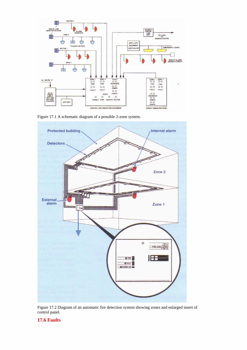
Figure 17.1 A schematic diagram of a possible 2-zone system.
Figure 17.2 Diagram of an automatic fire detection system showing zones and enlarged insert of control panel.
17.6 Faults
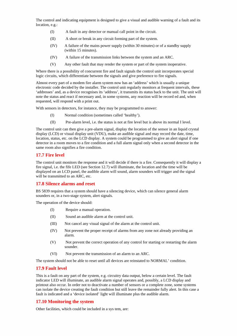
The control and indicating equipment is designed to give a visual and audible warning of a fault and its location, e.g.:
(I) A fault in any detector or manual call point in the circuit.
(II) A short or break in any circuit forming part of the system.
(IV) A failure of the mains power supply (within 30 minutes) or of a standby supply (within 15 minutes).
(IV) A failure of the transmission links between the system and an ARC.
(V) Any other fault that may render the system or part of the system inoperative.
Where there is a possibility of concurrent fire and fault signals the control unit incorporates special logic circuits, which differentiate between the signals and give preference to fire signals.
Almost every part of a modem fire alarm system now has an ‘address’ which is usually a unique electronic code decided by the installer. The control unit regularly monitors at frequent intervals, these ‘addresses’ and, as a device recognises its ‘address’, it transmits its status back to the unit. The unit will note the status and react if necessary and, in some systems, any reaction will be record ed and, when requested, will respond with a print out.
With sensors in detectors, for instance, they may be programmed to answer:
(I) Normal condition (sometimes called ‘healthy’).
(II) Pre-alarm level, i.e. the status is not at fire level but is above its normal I level.
The control unit can then give a pre-alarm signal, display the location of the sensor in an liquid crystal display (LCD) or visual display unit (VDU), make an audible signal and may record the date, time, location, status, etc. on the LCD display. A system could be programmed to give an alert signal if one detector in a room moves to a fire condition and a full alarm signal only when a second detector in the same room also signifies a fire condition.
17.7 Fire level The control unit monitors the response and it will decide if there is a fire. Consequently it will display a fire signal, i.e. the fife LED (see Section 12.7) will illuminate, the location and the time will be displayed on an LCD panel, the audible alarm will sound, alarm sounders will trigger and the signal will be transmitted to an ARC, etc.
17.8 Silence alarms and reset BS 5839 requires that a system should have a silencing device, which can silence general alarm sounders or, in a two-stage system, alert signals.
The operation of the device should:
(I) Require a manual operation.
(II) Sound an audible alarm at the control unit.
(III) Not cancel any visual signal of the alarm at the control unit.
(IV) Not prevent the proper receipt of alarms from any zone not already providing an alarm.
(V) Not prevent the correct operation of any control for starting or restarting the alarm sounder.
(VI) Not prevent the transmission of an alarm to an ARC.
The system should not be able to reset until all devices are reinstated to NORMAL’ condition.
17.9 Fault level This is a fault on any part of the system, e.g. circuitry data output, below a certain level. The fault indicator LED will illuminate, an audible alarm signal operates and, possibly, a LCD display and printout also occur. In order not to deactivate a number of sensors or a complete zone, some systems can isolate the device creating the fault condition but still leave the remainder fully alert. In this case a fault is indicated and a ‘device isolated’ light will illuminate plus the audible alarm.
17.10 Monitoring the system Other facilities, which could be included in a sys tem, are:
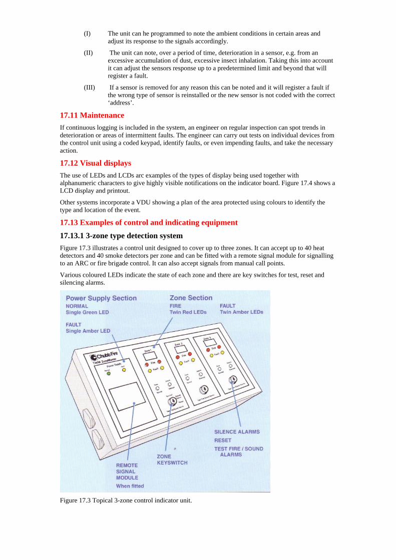
(I) The unit can he programmed to note the ambient conditions in certain areas and adjust its response to the signals accordingly.
(II) The unit can note, over a period of time, deterioration in a sensor, e.g. from an excessive accumulation of dust, excessive insect inhalation. Taking this into account it can adjust the sensors response up to a predetermined limit and beyond that will register a fault.
(III) If a sensor is removed for any reason this can be noted and it will register a fault if the wrong type of sensor is reinstalled or the new sensor is not coded with the correct ‘address’.
17.11 Maintenance If continuous logging is included in the system, an engineer on regular inspection can spot trends in deterioration or areas of intermittent faults. The engineer can carry out tests on individual devices from the control unit using a coded keypad, identify faults, or even impending faults, and take the necessary action.
17.12 Visual displays The use of LEDs and LCDs arc examples of the types of display being used together with alphanumeric characters to give highly visible notifications on the indicator board. Figure 17.4 shows a LCD display and printout.
Other systems incorporate a VDU showing a plan of the area protected using colours to identify the type and location of the event.
17.13 Examples of control and indicating equipment
17.13.1 3-zone type detection system Figure 17.3 illustrates a control unit designed to cover up to three zones. It can accept up to 40 heat detectors and 40 smoke detectors per zone and can be fitted with a remote signal module for signalling to an ARC or fire brigade control. It can also accept signals from manual call points.
Various coloured LEDs indicate the state of each zone and there are key switches for test, reset and silencing alarms.
Figure 17.3 Topical 3-zone control indicator unit.
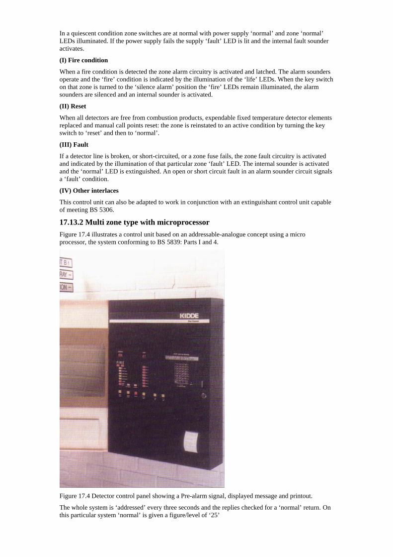
In a quiescent condition zone switches are at normal with power supply ‘normal’ and zone ‘normal’ LEDs illuminated. If the power supply fails the supply ‘fault’ LED is lit and the internal fault sounder activates.
(I) Fire condition
When a fire condition is detected the zone alarm circuitry is activated and latched. The alarm sounders operate and the ‘fire’ condition is indicated by the illumination of the ‘life’ LEDs. When the key switch on that zone is turned to the ‘silence alarm’ position the ‘fire’ LEDs remain illuminated, the alarm sounders are silenced and an internal sounder is activated.
(II) Reset
When all detectors are free from combustion products, expendable fixed temperature detector elements replaced and manual call points reset: the zone is reinstated to an active condition by turning the key switch to ‘reset’ and then to ‘normal’.
(III) Fault
If a detector line is broken, or short-circuited, or a zone fuse fails, the zone fault circuitry is activated and indicated by the illumination of that particular zone ‘fault’ LED. The internal sounder is activated and the ‘normal’ LED is extinguished. An open or short circuit fault in an alarm sounder circuit signals a ‘fault’ condition.
(IV) Other interlaces
This control unit can also be adapted to work in conjunction with an extinguishant control unit capable of meeting BS 5306.
17.13.2 Multi zone type with microprocessor Figure 17.4 illustrates a control unit based on an addressable-analogue concept using a micro processor, the system conforming to BS 5839: Parts I and 4.
Figure 17.4 Detector control panel showing a Pre-alarm signal, displayed message and printout.
The whole system is ‘addressed’ every three seconds and the replies checked for a ‘normal’ return. On this particular system ‘normal’ is given a figure/level of ‘25’
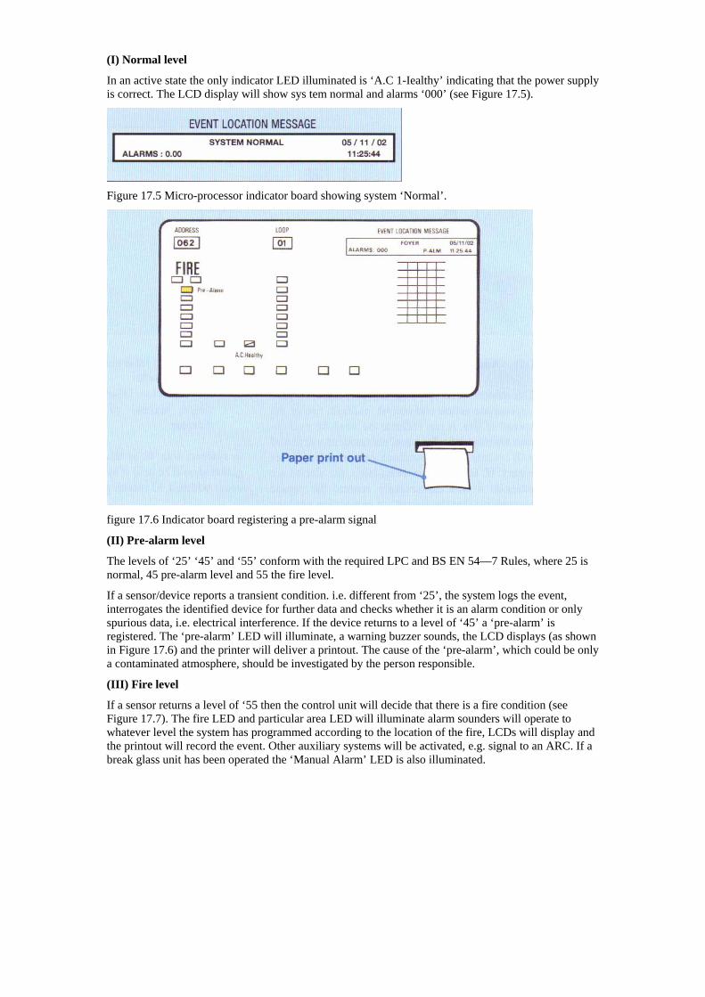
(I) Normal level
In an active state the only indicator LED illuminated is ‘A.C 1-Iealthy’ indicating that the power supply is correct. The LCD display will show sys tem normal and alarms ‘000’ (see Figure 17.5).
Figure 17.5 Micro-processor indicator board showing system ‘Normal’.
figure 17.6 Indicator board registering a pre-alarm signal
(II) Pre-alarm level
The levels of ‘25’ ‘45’ and ‘55’ conform with the required LPC and BS EN 54—7 Rules, where 25 is normal, 45 pre-alarm level and 55 the fire level.
If a sensor/device reports a transient condition. i.e. different from ‘25’, the system logs the event, interrogates the identified device for further data and checks whether it is an alarm condition or only spurious data, i.e. electrical interference. If the device returns to a level of ‘45’ a ‘pre-alarm’ is registered. The ‘pre-alarm’ LED will illuminate, a warning buzzer sounds, the LCD displays (as shown in Figure 17.6) and the printer will deliver a printout. The cause of the ‘pre-alarm’, which could be only a contaminated atmosphere, should be investigated by the person responsible.
(III) Fire level
If a sensor returns a level of ‘55 then the control unit will decide that there is a fire condition (see Figure 17.7). The fire LED and particular area LED will illuminate alarm sounders will operate to whatever level the system has programmed according to the location of the fire, LCDs will display and the printout will record the event. Other auxiliary systems will be activated, e.g. signal to an ARC. If a break glass unit has been operated the ‘Manual Alarm’ LED is also illuminated.
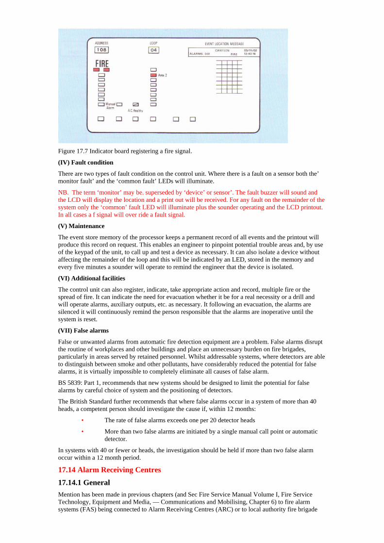
Figure 17.7 Indicator board registering a fire signal.
(IV) Fault condition
There are two types of fault condition on the control unit. Where there is a fault on a sensor both the’ monitor fault’ and the ‘common fault’ LEDs will illuminate.
NB. The term ‘monitor’ may be. superseded by ‘device’ or sensor’. The fault buzzer will sound and the LCD will display the location and a print out will be received. For any fault on the remainder of the system only the ‘common’ fault LED will illuminate plus the sounder operating and the LCD printout. In all cases a f signal will over ride a fault signal.
(V) Maintenance
The event store memory of the processor keeps a permanent record of all events and the printout will produce this record on request. This enables an engineer to pinpoint potential trouble areas and, by use of the keypad of the unit, to call up and test a device as necessary. It can also isolate a device without affecting the remainder of the loop and this will be indicated by an LED, stored in the memory and every five minutes a sounder will operate to remind the engineer that the device is isolated.
(VI) Additional facilities
The control unit can also register, indicate, take appropriate action and record, multiple fire or the spread of fire. It can indicate the need for evacuation whether it be for a real necessity or a drill and will operate alarms, auxiliary outputs, etc. as necessary. It following an evacuation, the alarms are silenced it will continuously remind the person responsible that the alarms are inoperative until the system is reset.
(VII) False alarms
False or unwanted alarms from automatic fire detection equipment are a problem. False alarms disrupt the routine of workplaces and other buildings and place an unnecessary burden on fire brigades, particularly in areas served by retained personnel. Whilst addressable systems, where detectors are able to distinguish between smoke and other pollutants, have considerably reduced the potential for false alarms, it is virtually impossible to completely eliminate all causes of false alarm.
BS 5839: Part 1, recommends that new systems should be designed to limit the potential for false alarms by careful choice of system and the positioning of detectors.
The British Standard further recommends that where false alarms occur in a system of more than 40 heads, a competent person should investigate the cause if, within 12 months:
• The rate of false alarms exceeds one per 20 detector heads
• More than two false alarms are initiated by a single manual call point or automatic detector.
In systems with 40 or fewer or heads, the investigation should be held if more than two false alarm occur within a 12 month period.
17.14 Alarm Receiving Centres
17.14.1 General Mention has been made in previous chapters (and Sec Fire Service Manual Volume I, Fire Service Technology, Equipment and Media, — Communications and Mobilising, Chapter 6) to fire alarm systems (FAS) being connected to Alarm Receiving Centres (ARC) or to local authority fire brigade
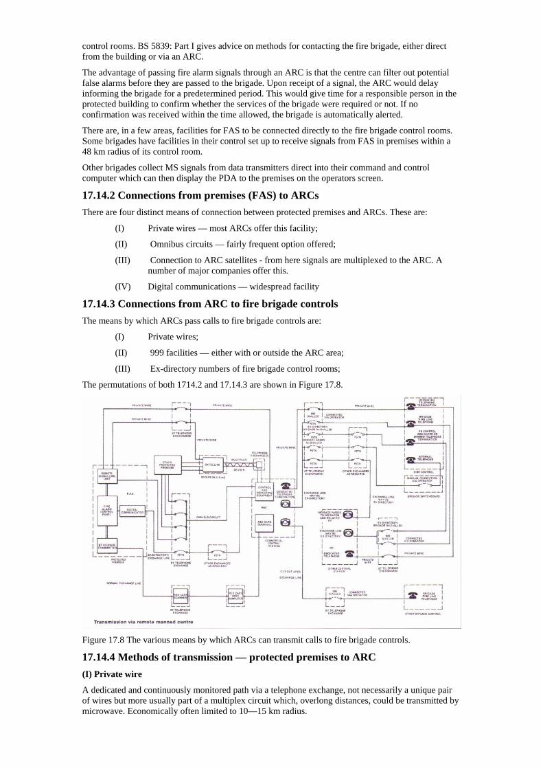
control rooms. BS 5839: Part I gives advice on methods for contacting the fire brigade, either direct from the building or via an ARC.
The advantage of passing fire alarm signals through an ARC is that the centre can filter out potential false alarms before they are passed to the brigade. Upon receipt of a signal, the ARC would delay informing the brigade for a predetermined period. This would give time for a responsible person in the protected building to confirm whether the services of the brigade were required or not. If no confirmation was received within the time allowed, the brigade is automatically alerted.
There are, in a few areas, facilities for FAS to be connected directly to the fire brigade control rooms. Some brigades have facilities in their control set up to receive signals from FAS in premises within a 48 km radius of its control room.
Other brigades collect MS signals from data transmitters direct into their command and control computer which can then display the PDA to the premises on the operators screen.
17.14.2 Connections from premises (FAS) to ARCs There are four distinct means of connection between protected premises and ARCs. These are:
(I) Private wires — most ARCs offer this facility;
(II) Omnibus circuits — fairly frequent option offered;
(III) Connection to ARC satellites - from here signals are multiplexed to the ARC. A number of major companies offer this.
(IV) Digital communications — widespread facility
17.14.3 Connections from ARC to fire brigade controls The means by which ARCs pass calls to fire brigade controls are:
(I) Private wires;
(II) 999 facilities — either with or outside the ARC area;
(III) Ex-directory numbers of fire brigade control rooms;
The permutations of both 1714.2 and 17.14.3 are shown in Figure 17.8.
Figure 17.8 The various means by which ARCs can transmit calls to fire brigade controls.
17.14.4 Methods of transmission — protected premises to ARC (I) Private wire
A dedicated and continuously monitored path via a telephone exchange, not necessarily a unique pair of wires but more usually part of a multiplex circuit which, overlong distances, could be transmitted by microwave. Economically often limited to 10—15 km radius.

(II) Omnibus circuits
In this system a number of premises share a communications path. Each premises has a dedicated spur connection to a telephone exchange from where there is a single circuit to the ARC. Due to line losses the number of premises on any one line are limited but it is economical over relatively long distances. Each premises is scanned together with the others but the code transmitted by the ARC only elicits an answer from one e.g. current state ‘normal’, ‘fault’ or ‘fire’.
(III) ARC satellites
A satellite is a form of data concentrator to which premises can be connected either by private wire of omnibus circuit. It is virtually an unstaffed ARC into which a large number of signals can be received and re-transmitted to an ARC, collecting data from a number of satellites. There is an added advantage that, if communications break down between a satellite and the ARC, an operator can affect the satellite although the multiplex systems are usually backed up by a duplication or by switching to the PSTN using modems.
(IV) Digital communications (DC)
This is a signalling device that is connected to an exchange telephone line. In the event of a fire signal operating at the premises the DC dials up the ARC using the PSTN. A receiver at the ARC answers and a series of coded tones is sent by the DC, decoded by the ARC receiver and displayed on the operators VDU for action. The advantage of this system is that there is no limit to distance of transmission and it is economic. The disadvantages are that, any congestion on the PSTN, and the signal may not go through however many times the DC is programmed to dial.
17.14.5 Methods of transmission (I) Private wire
Here the ARC resets a private circuit from a public telecommunications operator, e.g. British Telecom (BI) and this terminates in a brigade control. This makes a highly reliable connection but even this is usually backed up by a secondary method in case of failure.
(II) 999 facilities
If the ARC and protected premises happen to be located in the same area, BT will usually connect a 999 call from the ARC to the fire brigade control covering that area. Arrangements can be made to use the 999 system via an ‘out-of-area’ exchange line if the protected premises is in a different area to the ARC.
The disadvantage of using the 999 system is the human link, i.e. the BT operator, which could slow down the transmission of the call.
(III) Ex-directory number
A number of brigades provide an ARC with an ex-directory telephone number that permits access via the PSTN, to their control room and there the call is recognised as an emergency call. However, any use of the PSTN leaves a line susceptible to faults or den congestion and can cause delays in trans mission.
(IV) Administrative telephone number
This method is probably the most unacceptable although it is not unknown. There can be very significant delays in answering such calls, which have a low priority in any brigade control. It may even have to pass through a separate administrative switchboard before reaching the control; the line itself might be engaged; there may be a fault on the line or the PSTN may be congested.
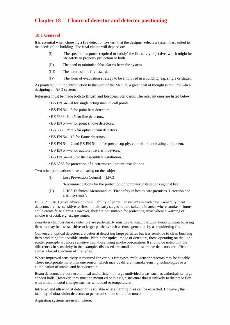
Chapter 18— Choice of detector and detector positioning
18.1 General It is essential when choosing a fire detection sys tern that the designer selects a system best suited to the needs of the building. The final choice will depend on:
(I) The speed of response required to satisfy’ the fire safety objective, which might be life safety or property protection or both.
(II) The need to minimise false alarms from the system.
(III) The nature of the fire hazard.
(IV) The form of evacuation strategy to be employed in a building, e.g. single or staged.
As pointed out in the introduction to this part of the Manual, a great deal of thought is required when designing an AFD system.
Reference must be made both to British and European Standards. The relevant ones are listed below:
• BS EN 54—Il for single acting manual call points.
• BS EN 54—5 for point heat detectors.
• BS 5839: Part 5 for line detectors.
• BS EN 54—7 for point smoke detectors.
• BS 5839: Part 5 for optical beam detectors.
• BS EN 54—10 for flame detectors.
• BS EN 54—2 and BS EN 54—4 for power sup ply, control and indicating equipment.
• BS EN 54—3 for audible fire alarm devices.
• BS EN 54—13 for the assembled installation.
• BS 6266 for protection of electronic equipment installations.
Two other publications have a bearing on the subject
(I) Loss Prevention Council (LPC)
‘Recommendations for the protection of computer installations against fire’.
(II) DHSS Technical Memorandum ‘Fire safety in health care premises. Detection and alarm systems’.
BS 5839: Part 1 gives advice on the suitability of particular systems in each case. Generally, heat detectors are less sensitive to fires in their early stages but are suitable in areas where smoke or fumes could create false alarms. However, they are not suitable for protecting areas where a warning of smoke is crucial, e.g. escape routes.
ionisation chamber smoke detectors are particularly sensitive to small particles found in clean burn ing fires bat may be less sensitive to larger particles such as those generated by a smouldering fire.
Conversely, optical detectors are better at detect ing large particles but less sensitive to clean burn ing fires producing little visible smoke. Within the optical range of detectors, those operating on the light scatter principle arc more sensitive than those using smoke obscuration. It should be noted that the differences in sensitivity in the examples discussed are small and most smoke detectors are efficient across a broad spectrum of fire types.
Where improved sensitivity is required for various fire types, multi-sensor detectors may be suitable. These incorporate more than one sensor, which may be different smoke-sensing technologies or a combination of smoke and heat detector.
Beam detectors are both economical and efficient in large undivided areas, such as cathedrals or large concert halls. However, they must be mount ed onto a rigid structure that is unlikely to distort or flex with environmental changes such as wind load or temperature.
Infra-red and ultra-violet detection is suitable where flaming fires can be expected. However, the inability of ultra-violet detectors to penetrate smoke should be noted.
Aspirating systems are useful where:
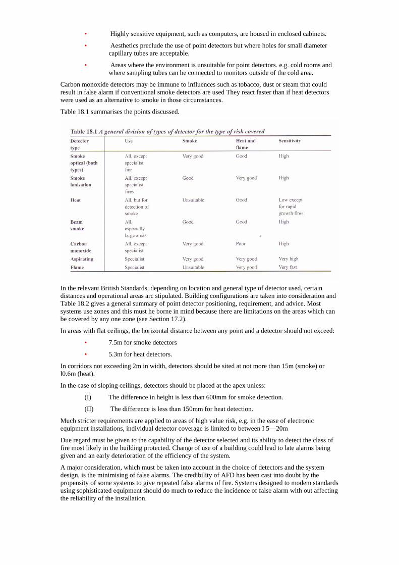
• Highly sensitive equipment, such as computers, are housed in enclosed cabinets.
• Aesthetics preclude the use of point detectors but where holes for small diameter capillary tubes are acceptable.
• Areas where the environment is unsuitable for point detectors. e.g. cold rooms and where sampling tubes can be connected to monitors outside of the cold area.
Carbon monoxide detectors may be immune to influences such as tobacco, dust or steam that could result in false alarm if conventional smoke detectors are used They react faster than if heat detectors were used as an alternative to smoke in those circumstances.
Table 18.1 summarises the points discussed.
In the relevant British Standards, depending on location and general type of detector used, certain distances and operational areas arc stipulated. Building configurations are taken into consideration and Table 18.2 gives a general summary of point detector positioning, requirement, and advice. Most systems use zones and this must he borne in mind because there are limitations on the areas which can be covered by any one zone (see Section 17.2).
In areas with flat ceilings, the horizontal distance between any point and a detector should not exceed:
• 7.5m for smoke detectors
• 5.3m for heat detectors.
In corridors not exceeding 2m in width, detectors should be sited at not more than 15m (smoke) or l0.6m (heat).
In the case of sloping ceilings, detectors should be placed at the apex unless:
(I) The difference in height is less than 600mm for smoke detection.
(II) The difference is less than 150mm for heat detection.
Much stricter requirements are applied to areas of high value risk, e.g. in the ease of electronic equipment installations, individual detector coverage is limited to between I 5—20m
Due regard must be given to the capability of the detector selected and its ability to detect the class of fire most likely in the building protected. Change of use of a building could lead to late alarms being given and an early deterioration of the efficiency of the system.
A major consideration, which must be taken into account in the choice of detectors and the system design, is the minimising of false alarms. The credibility of AFD has been cast into doubt by the propensity of some systems to give repeated false alarms of fire. Systems designed to modem standards using sophisticated equipment should do much to reduce the incidence of false alarm with out affecting the reliability of the installation.
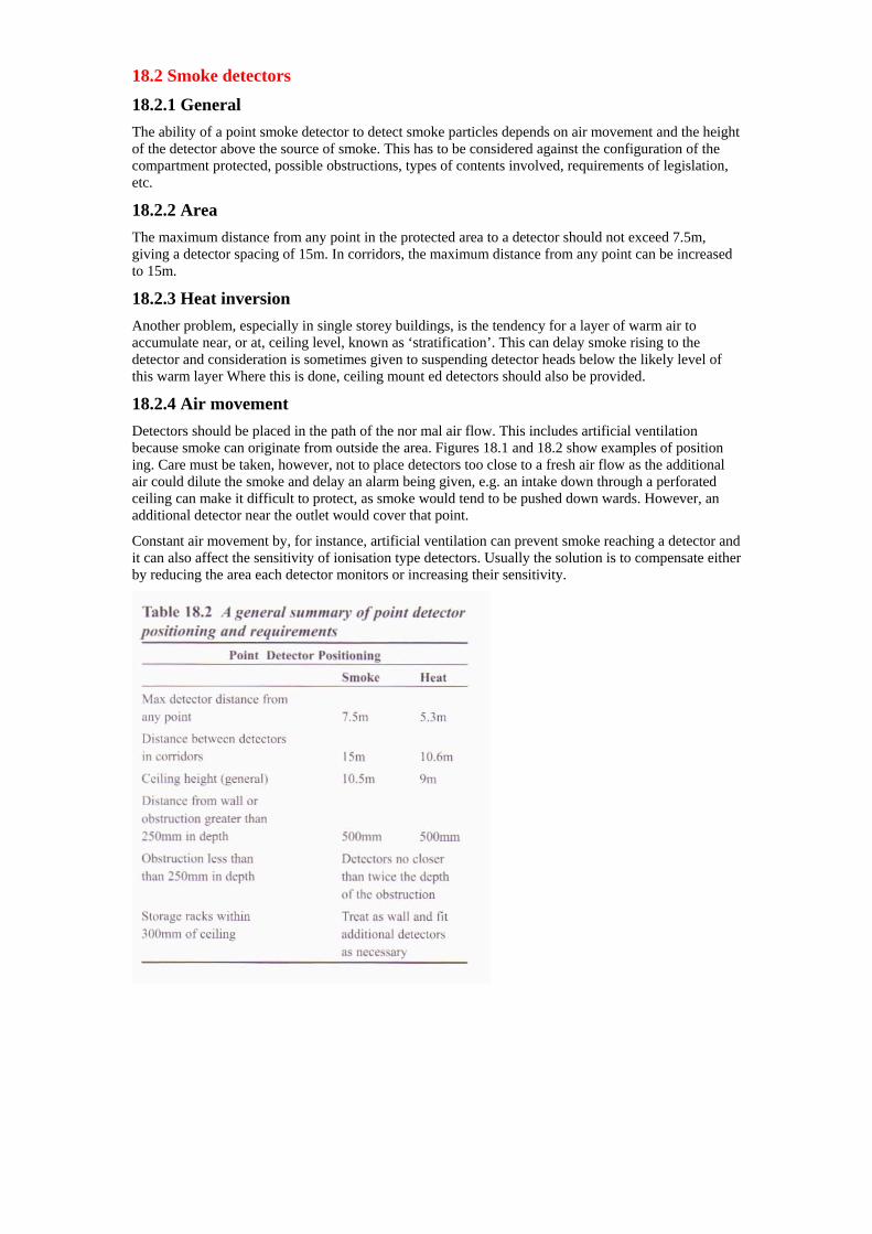
18.2 Smoke detectors
18.2.1 General The ability of a point smoke detector to detect smoke particles depends on air movement and the height of the detector above the source of smoke. This has to be considered against the configuration of the compartment protected, possible obstructions, types of contents involved, requirements of legislation, etc.
18.2.2 Area The maximum distance from any point in the protected area to a detector should not exceed 7.5m, giving a detector spacing of 15m. In corridors, the maximum distance from any point can be increased to 15m.
18.2.3 Heat inversion Another problem, especially in single storey buildings, is the tendency for a layer of warm air to accumulate near, or at, ceiling level, known as ‘stratification’. This can delay smoke rising to the detector and consideration is sometimes given to suspending detector heads below the likely level of this warm layer Where this is done, ceiling mount ed detectors should also be provided.
18.2.4 Air movement Detectors should be placed in the path of the nor mal air flow. This includes artificial ventilation because smoke can originate from outside the area. Figures 18.1 and 18.2 show examples of position ing. Care must be taken, however, not to place detectors too close to a fresh air flow as the additional air could dilute the smoke and delay an alarm being given, e.g. an intake down through a perforated ceiling can make it difficult to protect, as smoke would tend to be pushed down wards. However, an additional detector near the outlet would cover that point.
Constant air movement by, for instance, artificial ventilation can prevent smoke reaching a detector and it can also affect the sensitivity of ionisation type detectors. Usually the solution is to compensate either by reducing the area each detector monitors or increasing their sensitivity.
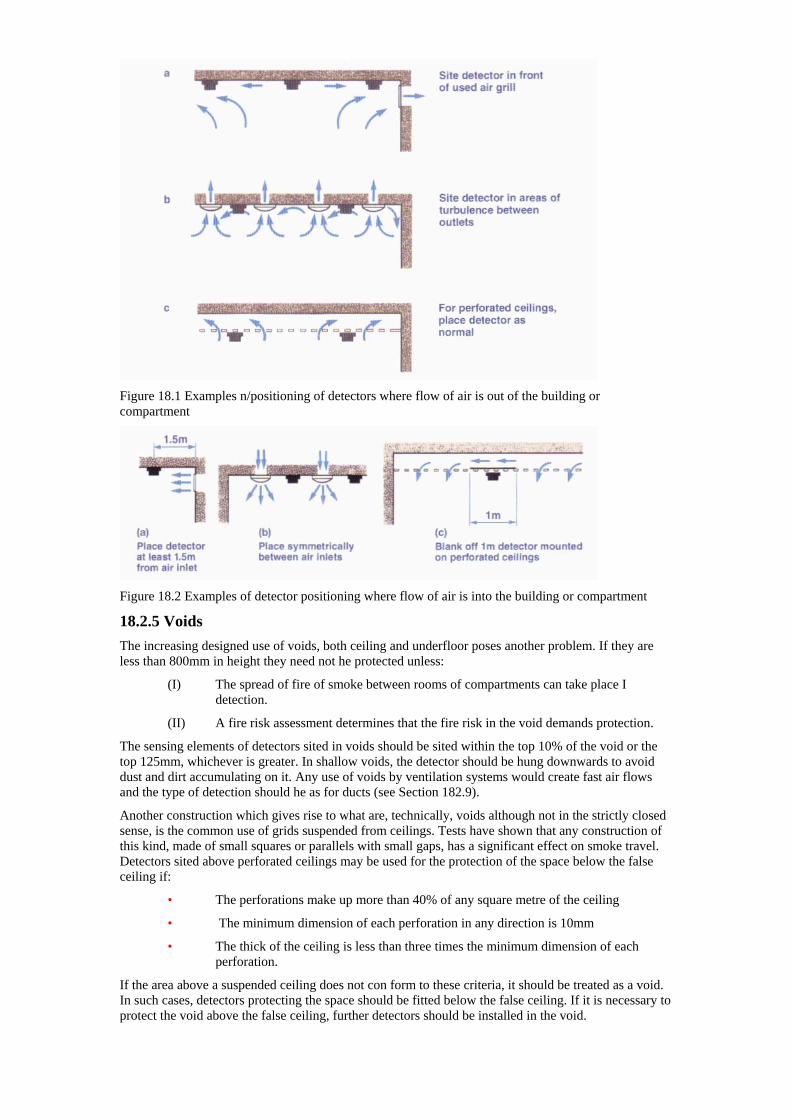
Figure 18.1 Examples n/positioning of detectors where flow of air is out of the building or compartment
Figure 18.2 Examples of detector positioning where flow of air is into the building or compartment
18.2.5 Voids The increasing designed use of voids, both ceiling and underfloor poses another problem. If they are less than 800mm in height they need not he protected unless:
(I) The spread of fire of smoke between rooms of compartments can take place I detection.
(II) A fire risk assessment determines that the fire risk in the void demands protection.
The sensing elements of detectors sited in voids should be sited within the top 10% of the void or the top 125mm, whichever is greater. In shallow voids, the detector should be hung downwards to avoid dust and dirt accumulating on it. Any use of voids by ventilation systems would create fast air flows and the type of detection should he as for ducts (see Section 182.9).
Another construction which gives rise to what are, technically, voids although not in the strictly closed sense, is the common use of grids suspended from ceilings. Tests have shown that any construction of this kind, made of small squares or parallels with small gaps, has a significant effect on smoke travel. Detectors sited above perforated ceilings may be used for the protection of the space below the false ceiling if:
• The perforations make up more than 40% of any square metre of the ceiling
• The minimum dimension of each perforation in any direction is 10mm
• The thick of the ceiling is less than three times the minimum dimension of each perforation.
If the area above a suspended ceiling does not con form to these criteria, it should be treated as a void. In such cases, detectors protecting the space should be fitted below the false ceiling. If it is necessary to protect the void above the false ceiling, further detectors should be installed in the void.
18.2.6 Walls, beams and galleries Positioning detectors within certain distances of walls or beams could put them into dead’ air space where there may be little or no air flow. Beams 150mm deep or less can be ignored but any beam more than 150mm or more than 10% of the height of the compartment should be treated as a separating wall for smoke travel purposes.
18.2.7 Corridors In a corridor, or a small room with a width of 2m or less, detectors can be spaced at 15m intervals.
18.2.8 Staircases, shafts, etc. In a staircase or shaft at least one detector should be placed on the top floor ceiling and on each main landing. In LI, L2, L3 and P1 systems (see Section 11.2), if any lift shaft, hoist, escalator or enclosed chute penetrates one or more ceilings, a detector should be placed at the head of each shaft and on each level within I .5m of the penetration (see Figure 18.3).
Figure 18.3 Detector positioning on a staircase
18.2.9 Ducts Smoke detectors in ventilation ducts are intended to assist with the prevention of the spread of smoke by shutting off the re-circulation system. Detectors in ducts should be connected to the fire alarm system but, as they would be ineffective when the system was shut down, they should be additional to detectors protecting the spaces served by the ventilation system.
BS 5839: Part 1 recommends that only smoke detectors arc used in ducts which may be probes from an aspirating system. The detectors or probes should be installed in straight stretches of duct work. To avoid air turbulence or smoke dilution by air from another source, the distance from any bend, corner or junction should not be less than three times the width of the duet.
18.2.10 Electronic equipment installations Fires in major electronic installations can have serious consequences. BS 6266 sets out the design criteria for the fire protection of electronic equipment installations and calls for a risk assessment. The latter should include an assessment of the con sequences of a fire in terms of actual loss and temporary loss of facility (downtime).
Most fire alarm and detection systems protecting electronic installations use highly sensitive smoke detection such as multi-sensor detectors or aspirating systems. In critical installations the aim is to accurately detect fire situations such as the early detection of an overheated cable.
The fire alarm and detection system is interfaced with the electronic installation to allow for a programmed shut down of the system, closing down the air conditioning or ventilation system serving the installation and the priming or release of any fixed fire suppression system.
The choice of detection system for electronic installations must ensure a high degree of reliability with the virtual elimination of the potential for false alarms.
18.3 Heat detectors
18.3.1 General Heat detectors are usually much slower in their reaction than smoke detectors but they are very reliable, require the minimum of maintenance and rarely give false alarms. Point heat detectors should conform to the requirements of BS EN 54—5, which defines eight classes of heat detector. Two relate to detectors suitable for installation in areas of normal ambient temperature, i.e. Classes Al or A2. The remaining Classes, B to U are intended for six different ranges of high ambient temperature.
The classification of heat detectors ensures that high ambient temperatures will not cause lower limit detectors to cause false alarms whilst ensuring that detectors classed for use in high ambient temperature conditions have an adequate speed of response.
This classification replaces the grading of heat detectors found in BS 5445 although detectors conforming to those grades are still in use. The grades are:
GRADE COLOUR
Grade 1 Green
Grade 2 Yellow
Grade 3 Red
18.3.2 Positioning With a few exceptions, the considerations for positioning heat detectors are the same as for smoke detectors.
The exceptions are:
(I) Height
Heat intensity decreases rapidly as distance increases, which means that the height limits are lower than those for smoke detectors. In each grade of detector (see 18.3.1 above) there is a maximum general limit height. Generally this is 9m for normal ambient temperature detectors (Classes Al and A2) and 7.5m for other classes. However, for Category P systems, where the fire brigade or private firefighting service minimum attendance time is not more than five minutes. the detector heights can be increased to 13.5m in the case of Class Al and A2 and 12m in all other eases.
Where ceiling heights are not consistent, detectors can be sited in the higher portions of the ceiling, providing the total area of those higher portions does not exceed 10% of the total ceiling area in any protected zone and the detector height does not exceed 10.5m for all classes of heat detector.
In contrast to smoke detectors, heat detectors should be sited so that the sensing element is not more than 50mm below the ceiling — which will determine whether heat detectors can he used.
(II) Area
The maximum distance allowed from any point to the nearest detector is 5.3m, giving a detector separation of l0.6m. In corridors, the maximum distance to the nearest detector can be increased to
lO.6m.
(III) Sloping ceilings
The detector should be sited in the apex of the roof
(IV) Beams and similar construction
The detector should be mounted on the ceiling only in the inter-beam area.
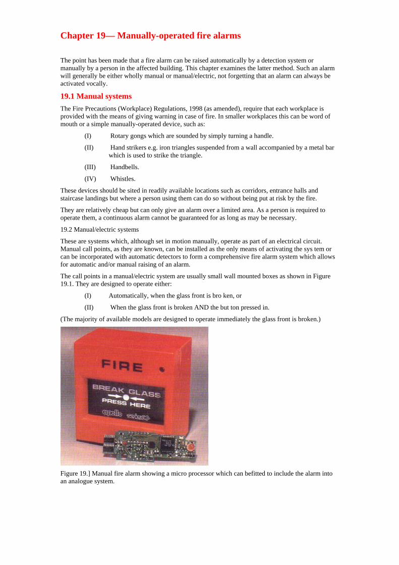
Chapter 19— Manually-operated fire alarms
The point has been made that a fire alarm can be raised automatically by a detection system or manually by a person in the affected building. This chapter examines the latter method. Such an alarm will generally be either wholly manual or manual/electric, not forgetting that an alarm can always be activated vocally.
19.1 Manual systems The Fire Precautions (Workplace) Regulations, 1998 (as amended), require that each workplace is provided with the means of giving warning in case of fire. In smaller workplaces this can be word of mouth or a simple manually-operated device, such as:
(I) Rotary gongs which are sounded by simply turning a handle.
(II) Hand strikers e.g. iron triangles suspended from a wall accompanied by a metal bar which is used to strike the triangle.
(III) Handbells.
(IV) Whistles.
These devices should be sited in readily available locations such as corridors, entrance halls and staircase landings but where a person using them can do so without being put at risk by the fire.
They are relatively cheap but can only give an alarm over a limited area. As a person is required to operate them, a continuous alarm cannot be guaranteed for as long as may be necessary.
19.2 Manual/electric systems
These are systems which, although set in motion manually, operate as part of an electrical circuit. Manual call points, as they are known, can be installed as the only means of activating the sys tem or can be incorporated with automatic detectors to form a comprehensive fire alarm system which allows for automatic and/or manual raising of an alarm.
The call points in a manual/electric system are usually small wall mounted boxes as shown in Figure 19.1. They are designed to operate either:
(I) Automatically, when the glass front is bro ken, or
(II) When the glass front is broken AND the but ton pressed in.
(The majority of available models are designed to operate immediately the glass front is broken.)
Figure 19.] Manual fire alarm showing a micro processor which can befitted to include the alarm into an analogue system.
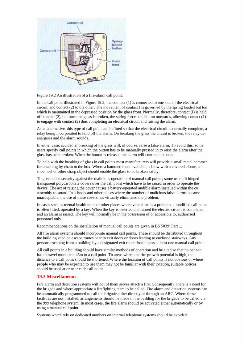
Figure 19.2 An illustration of a fire-alarm call point.
In the call point illustrated in Figure 19.2, the con tact (1) is connected to one side of the electrical circuit, and contact (2) to the other. The movement of contact ( is governed by the spring loaded but ton which is maintained in the depressed position by the glass front. Normally, therefore, contact (I) is held off contact (2), but once the glass is broken, the spring forces the button outwards, allowing contact (1) to engage with contact (2) thus completing an electrical circuit and raising the alarm.
As an alternative, this type of call point can befitted so that the electrical circuit is normally complete, a relay being incorporated to hold off the alarm. On breaking the glass the circuit is broken, the relay de-energises and the alarm sounds.
In either case, accidental breaking of the glass will, of course, raise a false alarm. To avoid this, some users specify call points in which the button has to he manually pressed in to raise the alarm after the glass has been broken. When the button is released the alarm will continue to sound.
To help with the breaking of glass in call points most manufacturers will provide a small metal hammer for attaching by chain to the box. Where a hammer is not available, a blow with a covered elbow, a shoe heel or other sharp object should enable the glass to be broken safely.
To give added security against the malicious operation of manual call points, some users fit hinged transparent polycarbonate covers over the call point which have to be raised in order to operate the device. The act of raising the cover causes a battery-operated audible alarm installed within the co assembly to sound. In schools and other places where the number of malicious false alarms became unacceptable, the use of these covers has virtually eliminated the problem.
In cases such as mental health units or other places where vandalism is a problem, a modified call point is often fitted, operated by a key. When the key is inserted and turned the electric circuit is completed and an alarm is raised. The key will normally be in the possession of or accessible to, authorised personnel only.
Recommendations on the installation of manual call points are given in BS 5839: Part 1.
All fire alarm systems should incorporate manual call points. These should be distributed throughout the building sited on escape routes near to exit doors or doors leading to enclosed stairways. Any persons escaping from a building by a designated exit route should pass at least one manual call point.
All call points in a building should have similar methods of operation and be sited so that no per son has to travel more than 45m to a call point. To areas where the fire growth potential is high, the distance to a call point should be shortened. Where the location of call points is not obvious or where people who may be expected to use them may not be familiar with their location, suitable notices should be used at or near each call point.
19.3 Miscellaneous Fire alarm and detection systems will not of them selves attack a fire. Consequently, there is a need for the brigade and where appropriate a firefighting team to he called. Fire alarm and detection systems can be automatically programmed to call the brigade either directly or through an ARC. Where these facilities are not installed, arrangements should he made in the building for the brigade to be called via the 999 telephone system. In most cases, the fire alarm should be activated either automatically or by using a manual call point.
Systems which rely on dedicated numbers on internal telephone systems should be avoided.
The telephone system could be disabled by the fire or other faults could delay the call being made. Similarly, arrangements which rely on a person intervening between the alarm system being activated and the alarm being given could lead to unacceptable delays.
19.4 Restricted alarms In order to avoid unnecessary disturbance in hospitals and other larger installations, it may be desirable to restrict an initial alarm to the locality in which it arises, or to a small number of restrict ed personnel. A general alarm would then be sounded only if a ‘duty officer’ considered it desirable to do so.
Signal light systems, which are often installed for summoning staff for various purposes, can be used for restricted alarms; operation of the call point produces a certain light code signal.
These lights may be installed at hospital ward entrances, passage intersections and other places where they are conspicuous to staff.
Restricted alarm systems must have a control point, which is under continuous and competent watch during the whole time the premises are occupied. An overriding switch should also be provided to enable the ‘duty officer’ or other responsible person to raise a general alarm for complete evacuation. In all cases it is essential to ensure that the fire brigade have been called. Firefighters should make themselves aware of the various types of systems in their area.
19.5 Smoke alarms Smoke alarms are produced primarily for use in the home, although they may have a limited application in other circumstances. A smoke alarm is a combined smoke detector and audible alarm. Emerging evidence shows that lives are being saved in homes fitted with these devices.
Smoke alarms should conform to BS 5446: Part I, and are of two basic types. They are:
(I) Iionising chamber,
(II) Optical, using either light obscuration or light scatter principles.
Power sources are either battery or mains electricity. Smoke alarms can operate independently or can be electrically interlinked to form a basic sys tem. Where alarms are interlinked, the activation of one alarm will trigger the audible devices in others.
Within the definition of smoke alarms a range of products are available. These include:
• Ionisation battery alarm
• Optical battery alarm
• Ionisation and optical alarm with mains power and /or battery.
Some manufacturers produce smoke alarms with additional facilities such as emergency lights which come on when the device is activated, hush or silencing buttons, strobe lights and vibrating pads to help those with sight or hearing difficulties.
In some battery-powered alarms, the battery is designed to power the device for periods up to 10 years. In most other eases, the battery has a limit ed life and should normally be changed annually.
Because smoke alarms are both detector and audible alarm, they need to be sited so that they will both detect fire in its early stages and alert every one in the home, particularly at night. Where more than one alarm unit is provided, these should be electrically interlinked for best results.
To be effective, all smoke alarms have to have a high degree of sensitivity and this can make them susceptible to false alarms such as smoke from cooking or steam from bathrooms. Ionisation detectors are more; prone to these effects than optical detectors. Careful siting of the detector will help prevent unwanted alarms as will keeping the detector clean.
Whilst there is no legislation demanding that occupiers fit smoke alarms, Approved Document B of the Building Regulations 2000 requires all new houses to be fitted with a mains-powered smoke alarm at each floor level and where more than one is provided for these to be interlinked.
Fire brigade personnel should take every opportunity to encourage householders to fit at least one smoke alarm in theft home and to check it regularly.
Further advice on the types of smoke alarms avail able and the types of installation recommended for a range of domestic premises can be found in BS 5839: Part 6.
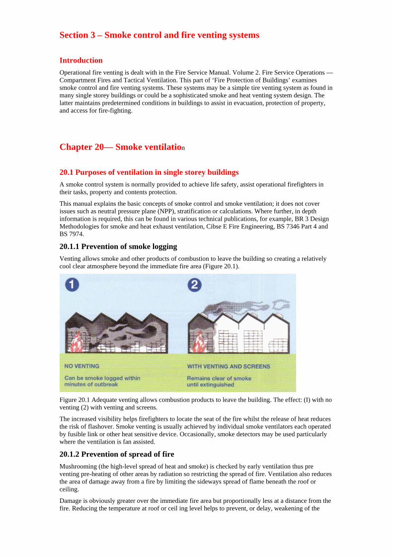
Section 3 – Smoke control and fire venting systems
Introduction Operational fire venting is dealt with in the Fire Service Manual. Volume 2. Fire Service Operations — Compartment Fires and Tactical Ventilation. This part of ‘Fire Protection of Buildings’ examines smoke control and fire venting systems. These systems may be a simple tire venting system as found in many single storey buildings or could be a sophisticated smoke and heat venting system design. The latter maintains predetermined conditions in buildings to assist in evacuation, protection of property, and access for fire-fighting.
Chapter 20— Smoke ventilation
20.1 Purposes of ventilation in single storey buildings A smoke control system is normally provided to achieve life safety, assist operational firefighters in their tasks, property and contents protection.
This manual explains the basic concepts of smoke control and smoke ventilation; it does not cover issues such as neutral pressure plane (NPP), stratification or calculations. Where further, in depth information is required, this can be found in various technical publications, for example, BR 3 Design Methodologies for smoke and heat exhaust ventilation, Cibse E Fire Engineering, BS 7346 Part 4 and BS 7974.
20.1.1 Prevention of smoke logging Venting allows smoke and other products of combustion to leave the building so creating a relatively cool clear atmosphere beyond the immediate fire area (Figure 20.1).
Figure 20.1 Adequate venting allows combustion products to leave the building. The effect: (I) with no venting (2) with venting and screens.
The increased visibility helps firefighters to locate the seat of the fire whilst the release of heat reduces the risk of flashover. Smoke venting is usually achieved by individual smoke ventilators each operated by fusible link or other heat sensitive device. Occasionally, smoke detectors may be used particularly where the ventilation is fan assisted.
20.1.2 Prevention of spread of fire Mushrooming (the high-level spread of heat and smoke) is checked by early ventilation thus pre venting pre-heating of other areas by radiation so restricting the spread of fire. Ventilation also reduces the area of damage away from a fire by limiting the sideways spread of flame beneath the roof or ceiling.
Damage is obviously greater over the immediate fire area but proportionally less at a distance from the fire. Reducing the temperature at roof or ceil ing level helps to prevent, or delay, weakening of the
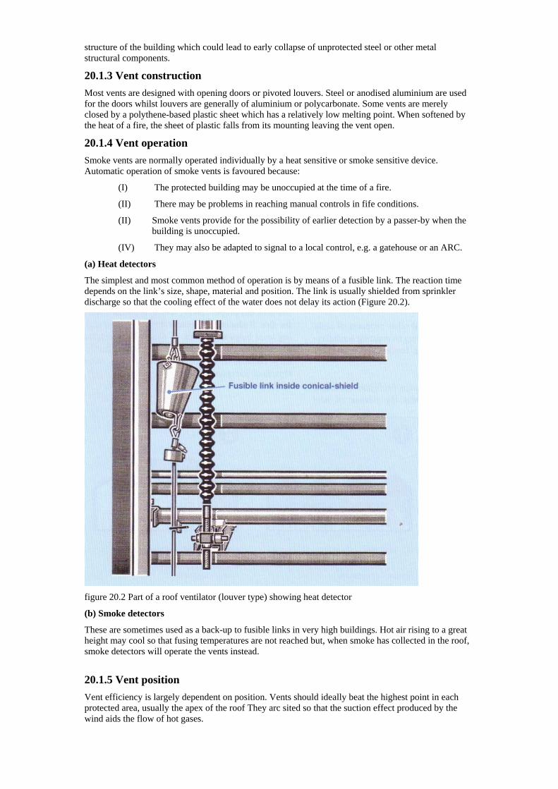
structure of the building which could lead to early collapse of unprotected steel or other metal structural components.
20.1.3 Vent construction Most vents are designed with opening doors or pivoted louvers. Steel or anodised aluminium are used for the doors whilst louvers are generally of aluminium or polycarbonate. Some vents are merely closed by a polythene-based plastic sheet which has a relatively low melting point. When softened by the heat of a fire, the sheet of plastic falls from its mounting leaving the vent open.
20.1.4 Vent operation Smoke vents are normally operated individually by a heat sensitive or smoke sensitive device. Automatic operation of smoke vents is favoured because:
(I) The protected building may be unoccupied at the time of a fire.
(II) There may be problems in reaching manual controls in fife conditions.
(II) Smoke vents provide for the possibility of earlier detection by a passer-by when the building is unoccupied.
(IV) They may also be adapted to signal to a local control, e.g. a gatehouse or an ARC.
(a) Heat detectors
The simplest and most common method of operation is by means of a fusible link. The reaction time depends on the link’s size, shape, material and position. The link is usually shielded from sprinkler discharge so that the cooling effect of the water does not delay its action (Figure 20.2).
figure 20.2 Part of a roof ventilator (louver type) showing heat detector
(b) Smoke detectors
These are sometimes used as a back-up to fusible links in very high buildings. Hot air rising to a great height may cool so that fusing temperatures are not reached but, when smoke has collected in the roof, smoke detectors will operate the vents instead.
20.1.5 Vent position Vent efficiency is largely dependent on position. Vents should ideally beat the highest point in each protected area, usually the apex of the roof They arc sited so that the suction effect produced by the wind aids the flow of hot gases.
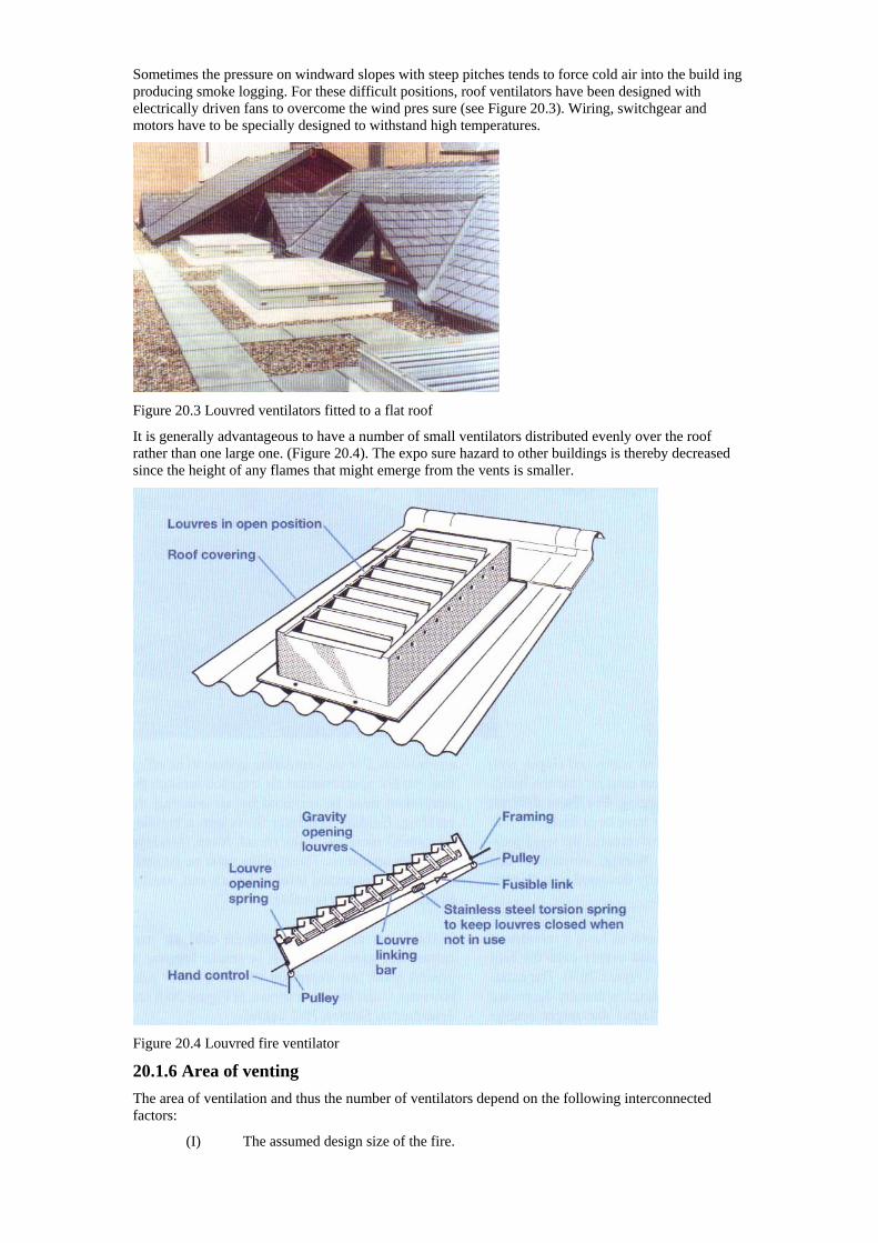
Sometimes the pressure on windward slopes with steep pitches tends to force cold air into the build ing producing smoke logging. For these difficult positions, roof ventilators have been designed with electrically driven fans to overcome the wind pres sure (see Figure 20.3). Wiring, switchgear and motors have to be specially designed to withstand high temperatures.
Figure 20.3 Louvred ventilators fitted to a flat roof
It is generally advantageous to have a number of small ventilators distributed evenly over the roof rather than one large one. (Figure 20.4). The expo sure hazard to other buildings is thereby decreased since the height of any flames that might emerge from the vents is smaller.
Figure 20.4 Louvred fire ventilator
20.1.6 Area of venting The area of ventilation and thus the number of ventilators depend on the following interconnected factors:
(I) The assumed design size of the fire.
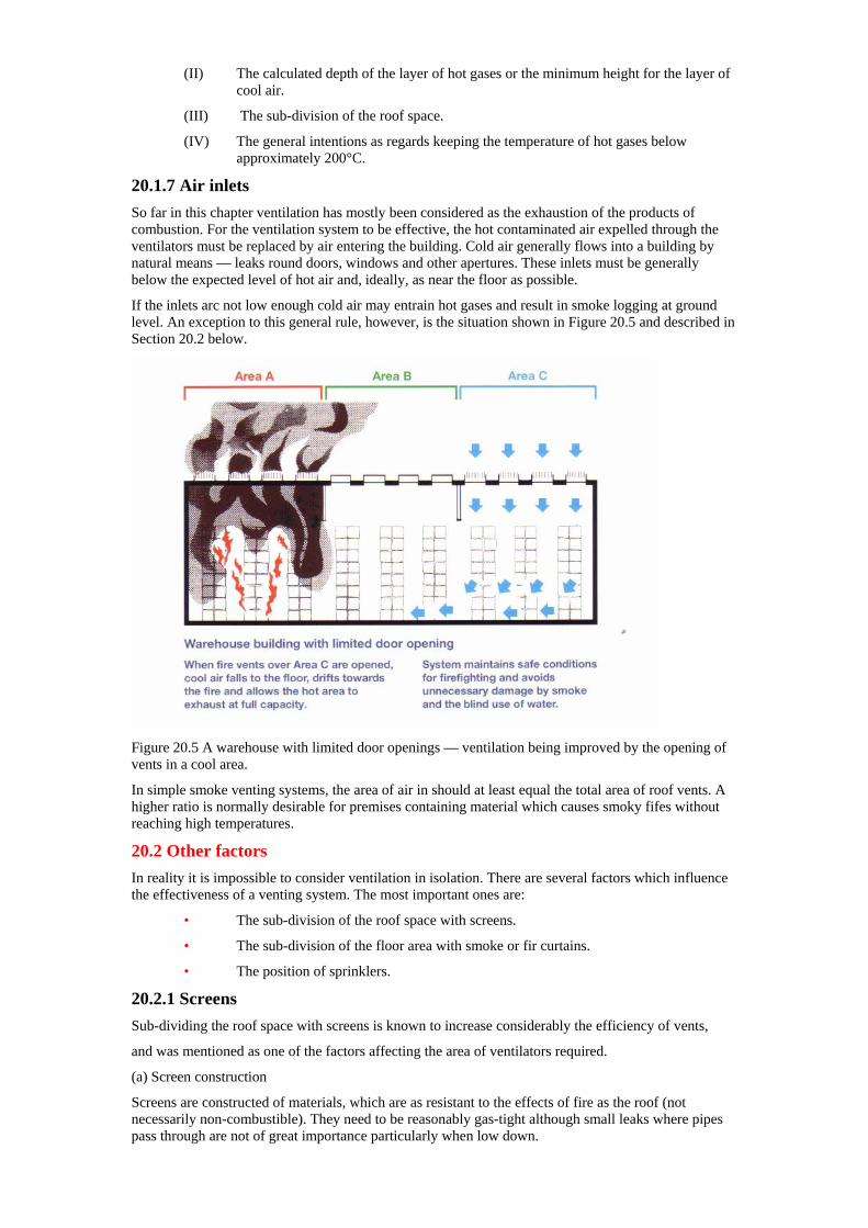
(II) The calculated depth of the layer of hot gases or the minimum height for the layer of cool air.
(III) The sub-division of the roof space.
(IV) The general intentions as regards keeping the temperature of hot gases below approximately 200°C.
20.1.7 Air inlets So far in this chapter ventilation has mostly been considered as the exhaustion of the products of combustion. For the ventilation system to be effective, the hot contaminated air expelled through the ventilators must be replaced by air entering the building. Cold air generally flows into a building by natural means — leaks round doors, windows and other apertures. These inlets must be generally below the expected level of hot air and, ideally, as near the floor as possible.
If the inlets arc not low enough cold air may entrain hot gases and result in smoke logging at ground level. An exception to this general rule, however, is the situation shown in Figure 20.5 and described in Section 20.2 below.
Figure 20.5 A warehouse with limited door openings — ventilation being improved by the opening of vents in a cool area.
In simple smoke venting systems, the area of air in should at least equal the total area of roof vents. A higher ratio is normally desirable for premises containing material which causes smoky fifes without reaching high temperatures.
20.2 Other factors In reality it is impossible to consider ventilation in isolation. There are several factors which influence the effectiveness of a venting system. The most important ones are:
• The sub-division of the roof space with screens.
• The sub-division of the floor area with smoke or fir curtains.
• The position of sprinklers.
20.2.1 Screens Sub-dividing the roof space with screens is known to increase considerably the efficiency of vents,
and was mentioned as one of the factors affecting the area of ventilators required.
(a) Screen construction
Screens are constructed of materials, which are as resistant to the effects of fire as the roof (not necessarily non-combustible). They need to be reasonably gas-tight although small leaks where pipes pass through are not of great importance particularly when low down.
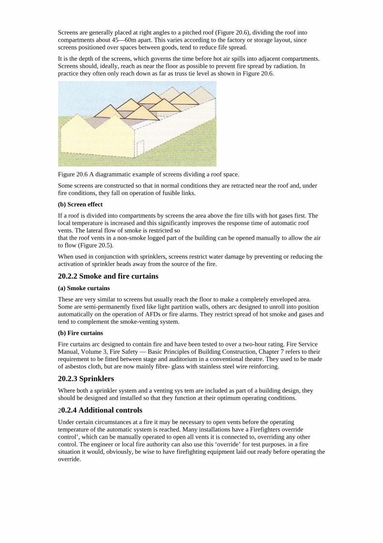
Screens are generally placed at right angles to a pitched roof (Figure 20.6), dividing the roof into compartments about 45—60m apart. This varies according to the factory or storage layout, since screens positioned over spaces between goods, tend to reduce fife spread.
It is the depth of the screens, which governs the time before hot air spills into adjacent compartments. Screens should, ideally, reach as near the floor as possible to prevent fire spread by radiation. In practice they often only reach down as far as truss tie level as shown in Figure 20.6.
Figure 20.6 A diagrammatic example of screens dividing a roof space.
Some screens are constructed so that in normal conditions they are retracted near the roof and, under fire conditions, they fall on operation of fusible links.
(b) Screen effect
If a roof is divided into compartments by screens the area above the fire tills with hot gases first. The local temperature is increased and this significantly improves the response time of automatic roof vents. The lateral flow of smoke is restricted so that the roof vents in a non-smoke logged part of the building can be opened manually to allow the air to flow (Figure 20.5).
When used in conjunction with sprinklers, screens restrict water damage by preventing or reducing the activation of sprinkler heads away from the source of the fire.
20.2.2 Smoke and fire curtains (a) Smoke curtains
These are very similar to screens but usually reach the floor to make a completely enveloped area. Some are semi-permanently fixed like light partition walls, others arc designed to unroll into position automatically on the operation of AFDs or fire alarms. They restrict spread of hot smoke and gases and tend to complement the smoke-venting system.
(b) Fire curtains
Fire curtains arc designed to contain fire and have been tested to over a two-hour rating. Fire Service Manual, Volume 3, Fire Safety — Basic Principles of Building Construction, Chapter 7 refers to their requirement to be fitted between stage and auditorium in a conventional theatre. They used to be made of asbestos cloth, but are now mainly fibre- glass with stainless steel wire reinforcing.
20.2.3 Sprinklers Where both a sprinkler system and a venting sys tem are included as part of a building design, they should be designed and installed so that they function at their optimum operating conditions.
20.2.4 Additional controls Under certain circumstances at a fire it may be necessary to open vents before the operating temperature of the automatic system is reached. Many installations have a Firefighters override control’, which can be manually operated to open all vents it is connected to, overriding any other control. The engineer or local fire authority can also use this ‘override’ for test purposes. in a fire situation it would, obviously, be wise to have firefighting equipment laid out ready before operating the override.
Chapter 21 — Smoke and heat exhaust ventilation systems (SHEVS)
21.1 Purposes of venting in complex buildings The development of modern building designs sometimes exceed the limits of fire safety set out in prescriptive building codes and standards. The distance people may have to travel to escape from a building or the use of temperature sensitive building materials make it necessary to restrict the fire growth potential and ensure that escape routes are free from hot smoke and gases.
Properly designed smoke and heat exhaust ventilation systems (SHEVS) provide a smoke free layer above a floor by removing smoke, so creating conditions for safe escape or access for firefighting. Smoke and heat exhaust ventilation systems arc expressly tailored for the building to which they are being applied using mathematical formulae developed specifically for that purpose.
21.2 Types of smoke and heat exhaust ventilation systems
There are two main types of SHEVS
• Natural ventilation;
• Powered ventilation.
Natural ventilation systems rely on the natural buoyancy of hot smoke and gases to rise and escape to atmosphere through automatic ventilators situated in the roof of a building.
Powered ventilation uses temperature rated fans, which start automatically to draw hot smoke and gases from the building.
21.2.1 Replacement air inlets As with smoke venting systems, without replacement air the ventilation system would not operate efficiently. The air removed either by natural or powered systems is replaced by air entering through inlets which automatically opened when the system is activated, Normal entrance doors are often used for this purpose. In natural ventilation systems, replacement air is sometimes supplied by fans. Total powered systems, sometimes referred to as “push-pull systems”, where both the inlet air and smoke exhaust are fan assisted are rarely used.
21.2.2 Performance of system Powered ventilation systems Work on a principle of a fixed rate of exhaust although that can be influenced by the factors below. The capacity of natural ventilation systems depends on a number of factors, including:
(I) The temperature of the smoke.
(II) The aerodynamic free area of the ventilators.
(III) The area of the inlet air openings.
(IV) Wind influence.
21.2.3 Use of smoke and heat exhaust ventilation systems (I) SHEVS maybe found in a range of buildings or structures, etc. including:
(a) single and multi-storey shopping malls;
(b) single and multi-storey industrial buildings and sprinklered warehouse;
(c) atria and complex buildings;
(d) enclosed car parks;
(e) stairways;
(f) tunnels.
(II) SHEVS can be used to:
(a) keep escape routes free from smoke;
(b) facilitate firefighting;
(c) reduce development of fire by reducing potential for flashover;
(d) reduce the heat effects on structures;
(e) reduce smoke damage.
21.2.4 Design of the system Smoke and heat exhaust ventilation systems are often arranged in zones. Each zone is separated from the other by walls and/or smoke barriers and has Is own smoke control system, powered or natural. Adjacent zones having powered systems may use a common extraction fan through interconnecting ducts. However, each zone should have its own replacement air inlet arrangements.
The system is triggered by a smoke detection sys tem in each zone. Where zones share a common extract fan, smoke control dampers in the common duct operate to ensure that only the fire zone is connected to the extract fan and that all other openings are closed.
21.2.5 System capacity The system is designed to exhaust smoke and heat from a predetermined fire size, known as the design fire. Calculations for design fires take into account the following factors:
(I) The nature of the materials present.
(II) The quality of materials present.
(III) The position of materials to walls, partitions and their configuration.
(IV) The availability of oxygen.
(V) The effectiveness of fire suppression devices.
When considering a design fire, the system designer will have to consider not only the flammability of materials likely to fuel a fire but also their ability to propagate smoke. For similar fuel sources, the intensity of a fire is usually determined by the amount of oxygen present.
Ventilated fires always have a plentiful supply of oxygen due to the inflow of replacement air. The ability of that air to reach the fire will depend on the configuration of the burning fuel. For example, stacked chairs will burn vigorously because the air can get into the fire from all sides and from under the fuel. Fires against walls deny access to air on the wall side whilst fires in the corner between two walls denies access on two sides. This results in a greater flame length up the wall
21.2.6 Operation of smoke and heat exhaust ventilation systems Buoyant smoke from a fire in a ventilated zone will rise into a smoke reservoir and trigger the smoke detection system. This will either cause the exhaust vents to open or start the exhaust fans in a powered system.
At the same time, the replacement air inlets will open so creating an air flow in the protected area. The smoke reservoir will fill to within a predetermined depth as the fire suppression system, e.g. sprinklers, maintains the fire size and the final temperature of the smoke within design limits. The system is then held in equilibrium until the fire is extinguished.
21.2.7 Conclusion Smoke and heat exhaust ventilation systems play an important part in ensuring people can safely escape from protected buildings whilst constraining the effects of fire in the building.
Further information on the design and calculation methods for smoke and heat exhaust ventilation systems can be found in BS 7346: Part 4. And BS 7974 4 Safety Engineering’ gives advice on the use of smoke and heat exhaust ventilation systems in complex buildings.
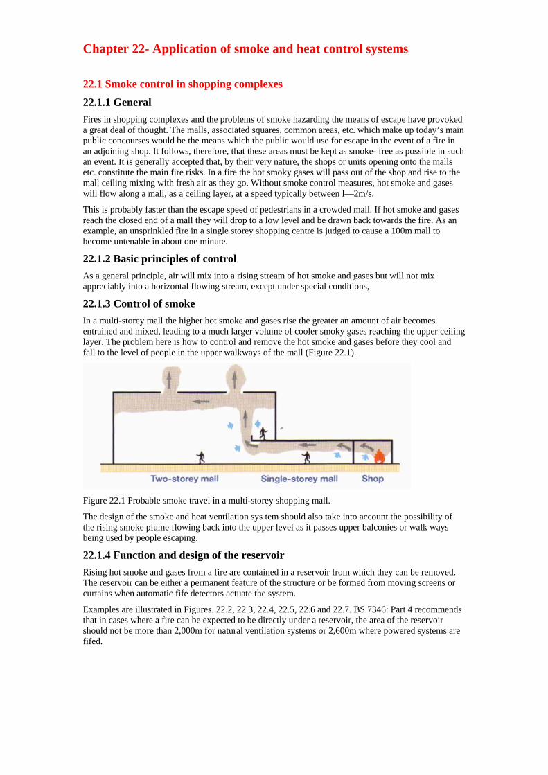
Chapter 22- Application of smoke and heat control systems
22.1 Smoke control in shopping complexes
22.1.1 General Fires in shopping complexes and the problems of smoke hazarding the means of escape have provoked a great deal of thought. The malls, associated squares, common areas, etc. which make up today’s main public concourses would be the means which the public would use for escape in the event of a fire in an adjoining shop. It follows, therefore, that these areas must be kept as smoke- free as possible in such an event. It is generally accepted that, by their very nature, the shops or units opening onto the malls etc. constitute the main fire risks. In a fire the hot smoky gases will pass out of the shop and rise to the mall ceiling mixing with fresh air as they go. Without smoke control measures, hot smoke and gases will flow along a mall, as a ceiling layer, at a speed typically between l—2m/s.
This is probably faster than the escape speed of pedestrians in a crowded mall. If hot smoke and gases reach the closed end of a mall they will drop to a low level and be drawn back towards the fire. As an example, an unsprinkled fire in a single storey shopping centre is judged to cause a 100m mall to become untenable in about one minute.
22.1.2 Basic principles of control As a general principle, air will mix into a rising stream of hot smoke and gases but will not mix appreciably into a horizontal flowing stream, except under special conditions,
22.1.3 Control of smoke In a multi-storey mall the higher hot smoke and gases rise the greater an amount of air becomes entrained and mixed, leading to a much larger volume of cooler smoky gases reaching the upper ceiling layer. The problem here is how to control and remove the hot smoke and gases before they cool and fall to the level of people in the upper walkways of the mall (Figure 22.1).
Figure 22.1 Probable smoke travel in a multi-storey shopping mall.
The design of the smoke and heat ventilation sys tem should also take into account the possibility of the rising smoke plume flowing back into the upper level as it passes upper balconies or walk ways being used by people escaping.
22.1.4 Function and design of the reservoir Rising hot smoke and gases from a fire are contained in a reservoir from which they can be removed. The reservoir can be either a permanent feature of the structure or be formed from moving screens or curtains when automatic fife detectors actuate the system.
Examples are illustrated in Figures. 22.2, 22.3, 22.4, 22.5, 22.6 and 22.7. BS 7346: Part 4 recommends that in cases where a fire can be expected to be directly under a reservoir, the area of the reservoir should not be more than 2,000m for natural ventilation systems or 2,600m where powered systems are fifed.
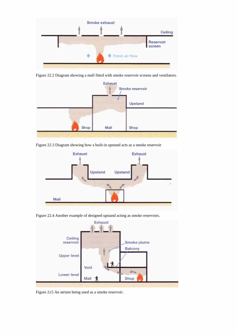
Figure 22.2 Diagram showing a mall fitted with smoke reservoir screens and ventilators.
Figure 22.3 Diagram showing how a built-in upstand acts as a smoke reservoir
Figure 22.4 Another example of designed upstand acting as smoke reservoirs.
Figure 2±5 An atrium being used as a smoke reservoir.

Where the hot smoke and gases from a fire in an adjoining shop unit have to flow into the mall before rising into the reservoir, the maximum area of the reservoir should not be more than 1000m² where natural ventilation systems or 1300m² for powered systems. This should ensure that the hot smoke and gases retain their buoyancy whilst being removed.
Equally, the hot smoke and gases should not be so hot (above 550°C) as to cause ignition of materials outside the immediate area of the fire.
22.1.5 Effects on people A reservoir should not be more than 60m long to avoid people having to move below the smoke layer becoming concerned. To ensure that people can escape below the hot smoke and gases the temperature of the base layer is calculated so as to be less than would cause painful heat radiation on them. The recommended clear height above escape routes in single storey malls or upper level walk ways is 3m.
22.1.6 Removal of hot smoke and gases (a) Rate of exhaust
Hot smoke and gases can be removed from the reservoirs either by natural or powered ventilation.
The rate of exhaust must equal the probable rate at which hot smoke and gases will enter the reservoir from below. Fresh air must enter the mall also at a rate equal to the rate of extraction and low enough not to prematurely mix with (and cool) the hot smoke and gases. The siting of the exit points where the hot smoke and gases leave the building needs consideration to avoid creating a hazard elsewhere.
(b) Wind effects
Where there is a likelihood that natural ventilation will be adversely affected by external wind forces on sloping roofs of more than 30 degrees, either the ventilator should be protected by wind shields or additional ventilators provided which are under the control of a wind sensor. Sufficient of the additional ventilators should be available at any one time to meet the needs of the system. Alternatively, powered ventilators should be provided (see Figure 22.8).
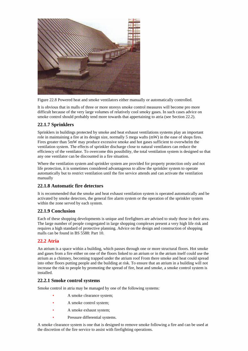
Figure 22.8 Powered heat and smoke ventilators either manually or automatically controlled.
It is obvious that in malls of three or more storeys smoke control measures will become pro more difficult because of the very large volumes of relatively cool smoky gases. In such cases advice on smoke control should probably tend more towards that appertaining to atria (see Section 22.2).
22.1.7 Sprinklers Sprinklers in buildings protected by smoke and heat exhaust ventilations systems play an important role in maintaining a fire at its design size, normally 5 mega wafts (mW) in the ease of shops fires. Fires greater than 5mW may produce excessive smoke and hot gases sufficient to overwhelm the ventilation system. The effects of sprinkler discharge close to natural ventilators can reduce the efficiency of the ventilator. To overcome this possibility, the total ventilation system is designed so that any one ventilator can be discounted in a fire situation.
Where the ventilation system and sprinkler system are provided for property protection only and not life protection, it is sometimes considered advantageous to allow the sprinkler system to operate automatically but to restrict ventilation until the fire service attends and can activate the ventilation manually
22.1.8 Automatic fire detectors It is recommended that the smoke and heat exhaust ventilation system is operated automatically and be activated by smoke detectors, the general fire alarm system or the operation of the sprinkler system within the zone served by each system.
22.1.9 Conclusion Each of these shopping developments is unique and firefighters are advised to study those in their area. The large number of people congregated in large shopping complexes present a very high life risk and requires a high standard of protective planning. Advice on the design and construction of shopping malls can be found in BS 5588: Part 10.
22.2 Atria An atrium is a space within a building, which passes through one or more structural floors. Hot smoke and gases from a fire either on one of the floors linked to an atrium or in the atrium itself could use the atrium as a chimney, becoming trapped under the atrium roof From there smoke and heat could spread into other floors putting people and the building at risk. To ensure that an atrium in a building will not increase the risk to people by promoting the spread of fire, heat and smoke, a smoke control system is installed.
22.2.1 Smoke control systems Smoke control in atria may be managed by one of the following systems:
• A smoke clearance system;
• A smoke control system;
• A smoke exhaust system;
• Pressure differential systems.
A smoke clearance system is one that is designed to remove smoke following a fire and can be used at the discretion of the fire service to assist with firefighting operations.
A smoke control system is one that controls the movement of smoke in a building to protect the contents, the means of escape and to assist with firefighting operations.
A smoke exhaust system is one that is designed to remove a sufficient volume of smoke to minimise the possibility of intercommunicating spaces becoming untenable due to heat and smoke.
An air pressure differential system is one where the air pressures between an atrium and linking floors are designed to control the movement of smoke between them.
22.2.2 Design of systems (I) Smoke systems
The design of smoke systems follows the concepts described earlier in this chapter. The atrium roof acts as a reservoir from where buoyant hot smoke and gases are released to the atmosphere through ventilators The ventilators can rely on the natural buoyancy of the hot smoke and gases or be powered. Air to replace that being exhausted in the form of hot smoke and gases is admitted to the atrium through low level vents.
(II) Pressure differential systems
Pressure differential systems either prevent smoke from a fire on an adjacent area from entering the atrium, or the system prevents smoke in an atrium from entering adjacent areas. This is achieved by the following techniques:
(a) The atrium can be depressurised. This would draw smoke from a fire in an adjacent area into the atrium but prevent it from invading adjacent areas.
(b) The adjacent areas can be pressurised which will have the same effect as in (a) above.
(c) The atrium can be pressurised. the aft flow venting through adjacent areas. This will prevent smoke from a fire in an adjacent area invading the atrium, the smoke being exhausted through an external vent in the affected area.
(III) Choice of system
The choice of system depends on a number of factors including:
• The height of the atrium
• The occupancy of the building
• The fife load at the atrium base
• The means of escape in case of fire
• The availability of sprinklers
• Fire resisting separation between the atrium and adjacent areas.
Smoke clearance systems are the simplest form of smoke control but are not generally considered suitable for the protection of the means of escape in case of fire for occupants of the building. The other more sophisticated options depend on a risk assessment taking the factors listed above into account.
22.2.3 Conclusion Smoke control is but one of a number of factors that have to be taken into account when designing adequate fire safety into building with atria. BS 55S8: Part 7 ‘Atria in Buildings’ gives further information on the design and fire precautions associated with atria including smoke control methods.
Chapter 23— Ventilation in multi-storey buildings
23.1 General Automatic fire venting as described in previous chapters is not generally applicable to multi-storey buildings. Although it is possible to treat the top storey as though it were a single storey and install automatic roof vents, they would have limited application — perhaps to vent smoke from lift shafts in a fire situation. In this chapter we examine the effects fixed ventilation and other ductwork can have on the spread of fire, heat and smoke and the methods used to restrict that potential.
23.1.1 Ductwork in buildings The use of fixed ducts for ventilation and air-conditioning systems in multi-storey buildings is now commonplace in modem buildings. The complexity of any system (see Figure 23.1) will depend on the size and layout of a building structure, number of floors served, work processes being carried on etc. Ductwork serving a ventilation or air-conditioning system is a potential route for the spread of smoke and hot gases.
Measures have been devised to control the potential fire hazard of these systems. Such measures are designed:
(I) To limit or prevent the spread of fire, heat and smoke into other parts of the building
and in particular escape routes.
(II) To facilitate firefighting.
(III) To reduce damage.
23.1.2 Systems used Ventilation systems may be divided into three main groups; those in which:
(I) Stale air is extracted by fans (fresh air find ing its way in through windows and doors) — known as ‘exhaust’ ventilation.
(II) Fresh air is forced in by fans (stale air find ing its way out through windows and doors) — known as ‘plenum’ ventilation.
(III) Fans are used to force in fresh aft and extract stale air. This is a combination of (I) and (ii) and is known as ‘balanced’ ventilation.
23.1.3 Air conditioning systems Air conditioning systems are balanced systems. They either heat the air through heat exchangers, often fed by hot water or steam from boilers or cool the air by means of a refrigeration process. In smaller systems the heat may be provided electrically. To save energy, air conditioning plants incorporate a degree of re-circulation where approximately 75% of the air is returned to the air conditioning plant, mixed with fresh air, re-heated or cooled and re-circulated.
23.1.4 Plant rooms All installations have at least one plant room, normally located on the roof or in the basement. Large buildings may have many plant rooms, located throughout the premises, sometimes supervised from a central control room readily accessible to fire service personnel responding to an incident.
A plant room should be separated from the remainder of the building by floors, ceilings walls or partitions having a fire resistance of at least one horn, depending on its location. In the case of air-conditioning plant, gas fired boilers, or occasionally oil fired boilers, may be used to warm the air, Freon or other refrigerants used to cool it. These substances present a hazard in themselves and as a precaution the BS 5583: Part 9 recommends the installation of a fire-detection system which would automatically close down the plant in a fire situation.
23.1.5 Components of systems Another relevant component of ventilation systems from the fire hazard viewpoint are air filters. Normally situated in the plant room, their function is to reduce the dust content of incoming air. There are three main types of filter used:
• Dry filter
• Viscous filter
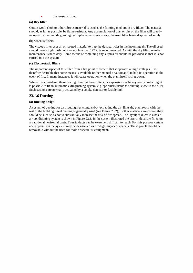
• Electrostatic filter.
(a) Dry filter
Cotton wool, cloth or other fibrous material is used as the filtering medium in dry filters. The material should, as far as possible, be flame resistant. Any accumulation of dust or dirt on the filter will greatly increase its flammability, so regular replacement is necessary, the used filter being disposed of safely.
(b) Viscous filters
The viscous filter uses an oil-coated material to trap the dust particles in the incoming air. The oil used should have a high flash point — not less than 177°C is recommended. As with the dry filter, regular maintenance is necessary. Some means of containing any surplus oil should be provided so that it is not carried into the system.
(c) Electrostatic filters
The important aspect of this filter from a fire point of view is that it operates at high voltages. It is therefore desirable that some means is available (either manual or automatic) to halt its operation in the event of fire. In many instances it will cease operation when the plant itself is shut down.
Where it is considered there is a high fire risk from filters, or expensive machinery needs protecting, it is possible to fit an automatic extinguishing system, e.g. sprinklers inside the ducting, close to the filter. Such systems are normally activated by a smoke detector or fusible link
23.1.6 Ducting (a) Ducting design
A system of ducting for distributing, recycling and/or extracting the air, links the plant room with the rest of the building. Steel ducting is generally used (see Figure 23.2); if other materials are chosen they should be such so as not to substantially increase the risk of fire spread. The layout of ducts in a basic air-conditioning system is shown in Figure 23.1. In the system illustrated the branch ducts are fitted on a traditional horizontal basis. Fires in ducts can be extremely difficult to reach. For this purpose certain access panels in the sys tem may be designated as fire-fighting access panels. These panels should be removable without the need for tools or specialist equipment.
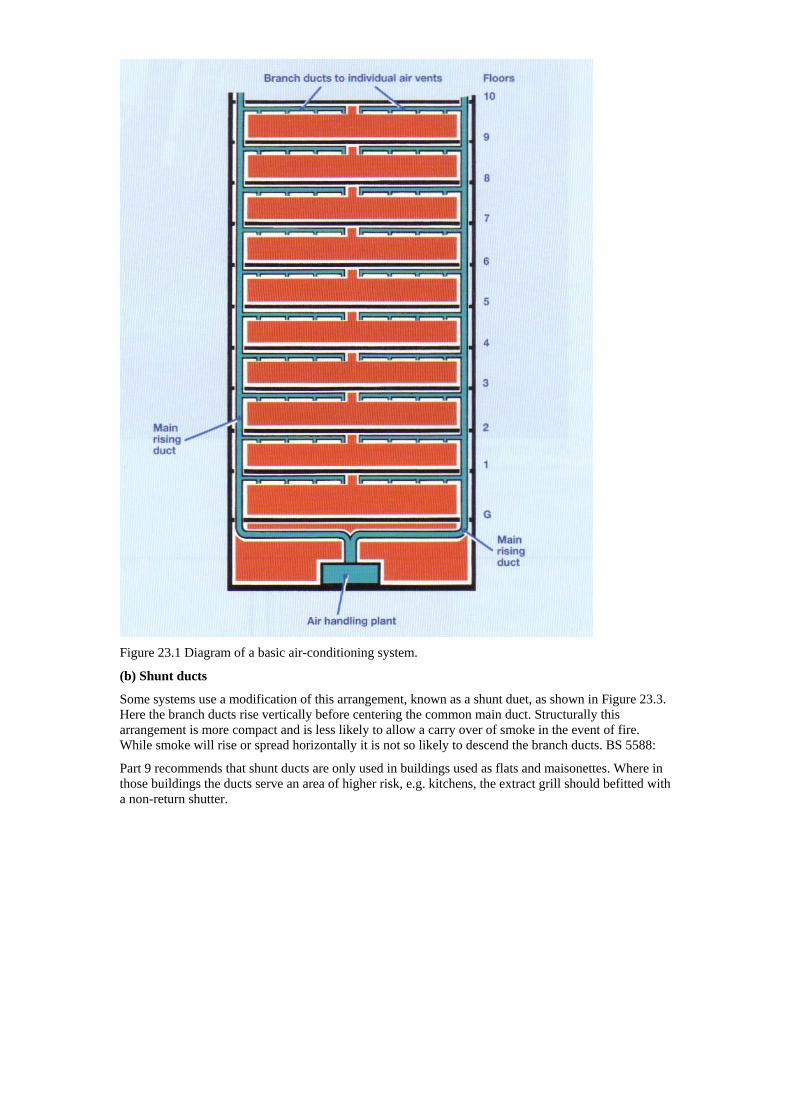
Figure 23.1 Diagram of a basic air-conditioning system.
(b) Shunt ducts
Some systems use a modification of this arrangement, known as a shunt duet, as shown in Figure 23.3. Here the branch ducts rise vertically before centering the common main duct. Structurally this arrangement is more compact and is less likely to allow a carry over of smoke in the event of fire. While smoke will rise or spread horizontally it is not so likely to descend the branch ducts. BS 5588:
Part 9 recommends that shunt ducts are only used in buildings used as flats and maisonettes. Where in those buildings the ducts serve an area of higher risk, e.g. kitchens, the extract grill should befitted with a non-return shutter.
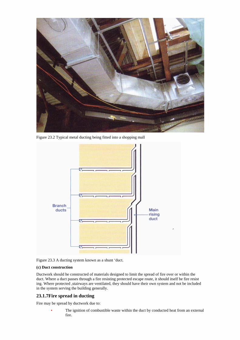
Figure 23.2 Typical metal ducting being fitted into a shopping mall
Figure 23.3 A ducting system known as a shunt ‘duct.
(c) Duct construction
Ductwork should he constructed of materials designed to limit the spread of fire over or within the duct. Where a duct passes through a fire resisting protected escape route, it should itself be fire resist ing. Where protected ,stairways are ventilated, they should have their own system and not be included in the system serving the building generally.
23.1.7Fire spread in ducting Fire may be spread by ductwork due to:
• The ignition of combustible waste within the duct by conducted heat from an external fire.
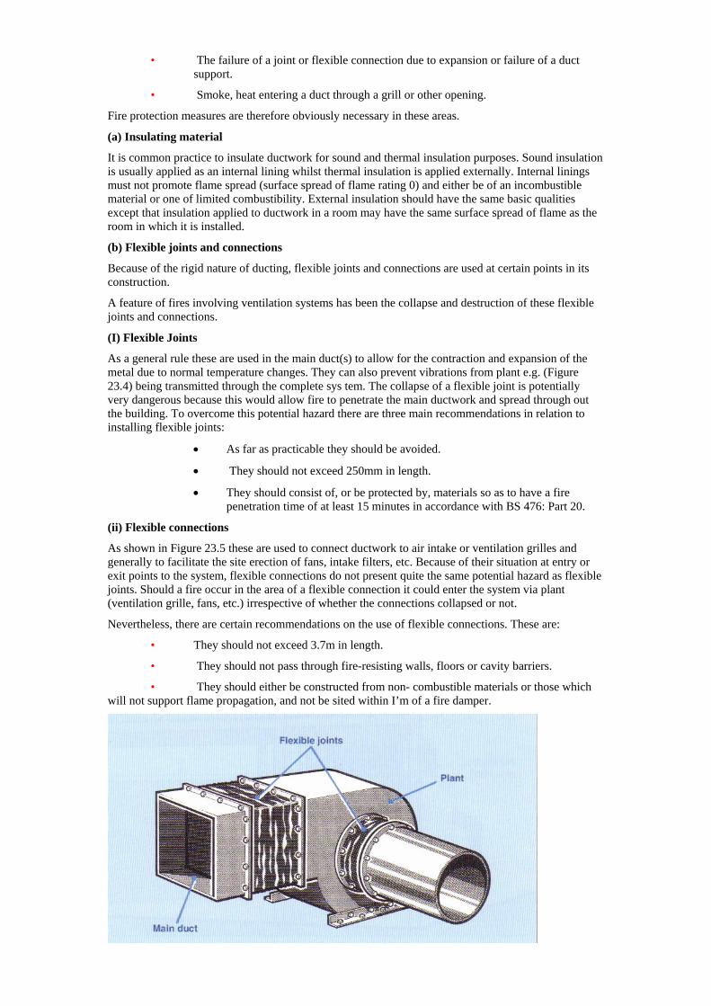
• The failure of a joint or flexible connection due to expansion or failure of a duct support.
• Smoke, heat entering a duct through a grill or other opening.
Fire protection measures are therefore obviously necessary in these areas.
(a) Insulating material
It is common practice to insulate ductwork for sound and thermal insulation purposes. Sound insulation is usually applied as an internal lining whilst thermal insulation is applied externally. Internal linings must not promote flame spread (surface spread of flame rating 0) and either be of an incombustible material or one of limited combustibility. External insulation should have the same basic qualities except that insulation applied to ductwork in a room may have the same surface spread of flame as the room in which it is installed.
(b) Flexible joints and connections
Because of the rigid nature of ducting, flexible joints and connections are used at certain points in its construction.
A feature of fires involving ventilation systems has been the collapse and destruction of these flexible joints and connections.
(I) Flexible Joints
As a general rule these are used in the main duct(s) to allow for the contraction and expansion of the metal due to normal temperature changes. They can also prevent vibrations from plant e.g. (Figure 23.4) being transmitted through the complete sys tem. The collapse of a flexible joint is potentially very dangerous because this would allow fire to penetrate the main ductwork and spread through out the building. To overcome this potential hazard there are three main recommendations in relation to installing flexible joints:
• As far as practicable they should be avoided.
• They should not exceed 250mm in length.
• They should consist of, or be protected by, materials so as to have a fire penetration time of at least 15 minutes in accordance with BS 476: Part 20.
(ii) Flexible connections
As shown in Figure 23.5 these are used to connect ductwork to air intake or ventilation grilles and generally to facilitate the site erection of fans, intake filters, etc. Because of their situation at entry or exit points to the system, flexible connections do not present quite the same potential hazard as flexible joints. Should a fire occur in the area of a flexible connection it could enter the system via plant (ventilation grille, fans, etc.) irrespective of whether the connections collapsed or not.
Nevertheless, there are certain recommendations on the use of flexible connections. These are:
• They should not exceed 3.7m in length.
• They should not pass through fire-resisting walls, floors or cavity barriers.
• They should either be constructed from non- combustible materials or those which will not support flame propagation, and not be sited within I’m of a fire damper.
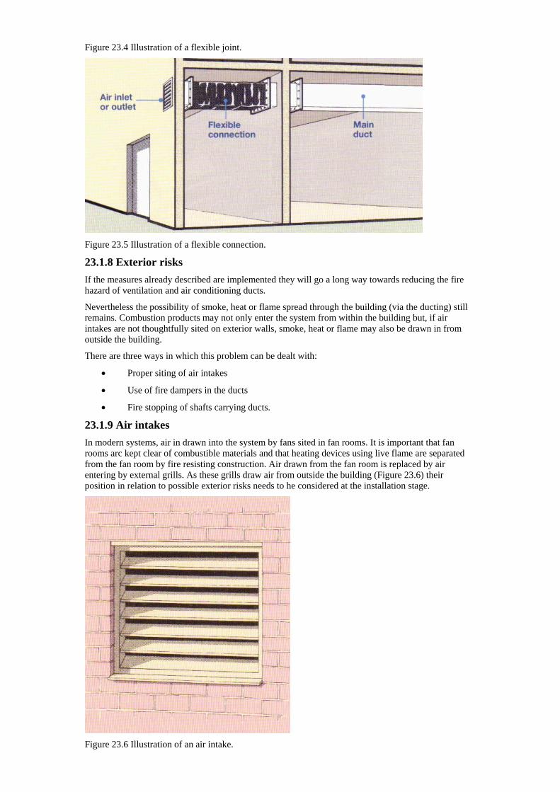
Figure 23.4 Illustration of a flexible joint.
Figure 23.5 Illustration of a flexible connection.
23.1.8 Exterior risks If the measures already described are implemented they will go a long way towards reducing the fire hazard of ventilation and air conditioning ducts.
Nevertheless the possibility of smoke, heat or flame spread through the building (via the ducting) still remains. Combustion products may not only enter the system from within the building but, if air intakes are not thoughtfully sited on exterior walls, smoke, heat or flame may also be drawn in from outside the building.
There are three ways in which this problem can be dealt with:
• Proper siting of air intakes
• Use of fire dampers in the ducts
• Fire stopping of shafts carrying ducts.
23.1.9 Air intakes In modern systems, air in drawn into the system by fans sited in fan rooms. It is important that fan rooms arc kept clear of combustible materials and that heating devices using live flame are separated from the fan room by fire resisting construction. Air drawn from the fan room is replaced by air entering by external grills. As these grills draw air from outside the building (Figure 23.6) their position in relation to possible exterior risks needs to he considered at the installation stage.
Figure 23.6 Illustration of an air intake.
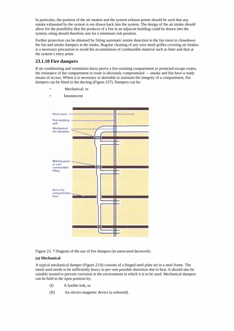
In particular, the position of the air intakes and the system exhaust points should he such that any smoke exhausted by the system is not drawn back into the system. The design of the air intake should allow for the possibility that the products of a fire in an adjacent building could be drawn into the system; siting should therefore aim for a minimum risk position.
Further protection can be obtained by fitting automatic smoke detection in the fan room to closedown the fan and smoke dampers at the intake. Regular cleaning of any wire mesh grilles covering air intakes is a necessary precaution to avoid the accumulation of combustible material such as litter and dust at the system’s entry point.
23.1.10 Fire dampers If air conditioning and ventilation ducts pierce a fire-resisting compartment or protected escape routes, the resistance of the compartment or route is obviously compromised — smoke and fire have a ready means of access. Where it is necessary or desirable to maintain the integrity of a compartment, fire dampers can be fitted in the ducting (Figure 237). Dampers can be:
• Mechanical; or
• Intumescent
Figure 23. 7 Diagram of the use of fire dampers (in unencased ductwork)
(a) Mechanical
A typical mechanical damper (Figure 23.8) consists of a hinged steel plate set in a steel frame. The metal used needs to be sufficiently heavy to pre vent possible distortion due to heat. It should also be suitably treated to prevent corrosion in the environment in which it is to be used. Mechanical dampers can be held in the open position by:
(I) A fusible link, or
(II) An electro-magnetic device (a solenoid).
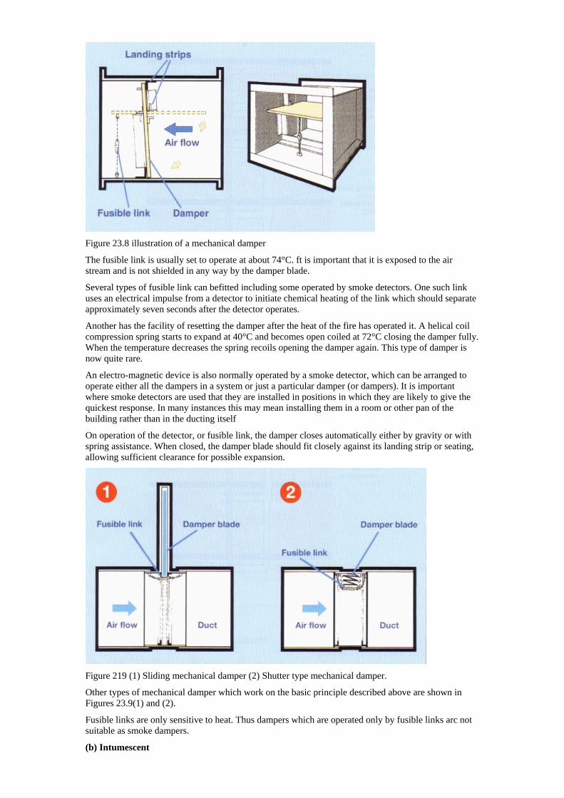
Figure 23.8 illustration of a mechanical damper
The fusible link is usually set to operate at about 74°C. ft is important that it is exposed to the air stream and is not shielded in any way by the damper blade.
Several types of fusible link can befitted including some operated by smoke detectors. One such link uses an electrical impulse from a detector to initiate chemical heating of the link which should separate approximately seven seconds after the detector operates.
Another has the facility of resetting the damper after the heat of the fire has operated it. A helical coil compression spring starts to expand at 40°C and becomes open coiled at 72°C closing the damper fully. When the temperature decreases the spring recoils opening the damper again. This type of damper is now quite rare.
An electro-magnetic device is also normally operated by a smoke detector, which can be arranged to operate either all the dampers in a system or just a particular damper (or dampers). It is important where smoke detectors are used that they are installed in positions in which they are likely to give the quickest response. In many instances this may mean installing them in a room or other pan of the building rather than in the ducting itself
On operation of the detector, or fusible link, the damper closes automatically either by gravity or with spring assistance. When closed, the damper blade should fit closely against its landing strip or seating, allowing sufficient clearance for possible expansion.
Figure 219 (1) Sliding mechanical damper (2) Shutter type mechanical damper.
Other types of mechanical damper which work on the basic principle described above are shown in Figures 23.9(1) and (2).
Fusible links are only sensitive to heat. Thus dampers which are operated only by fusible links arc not suitable as smoke dampers.
(b) Intumescent
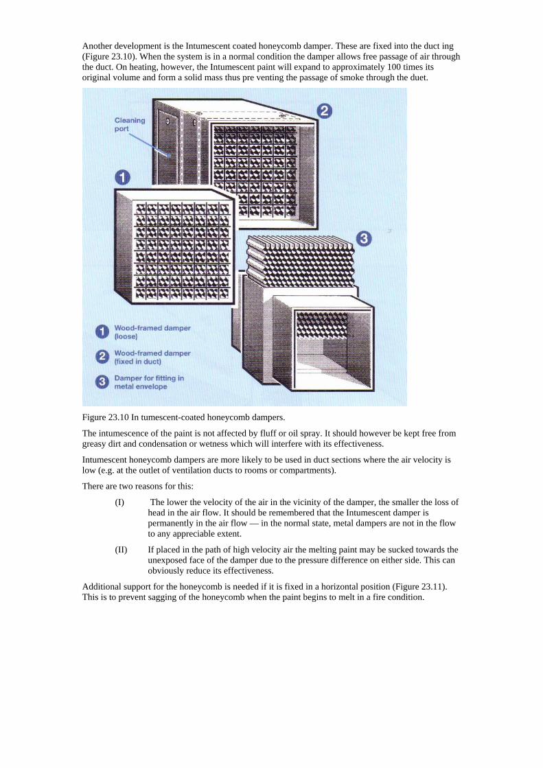
Another development is the Intumescent coated honeycomb damper. These are fixed into the duct ing (Figure 23.10). When the system is in a normal condition the damper allows free passage of air through the duct. On heating, however, the Intumescent paint will expand to approximately 100 times its original volume and form a solid mass thus pre venting the passage of smoke through the duet.
Figure 23.10 In tumescent-coated honeycomb dampers.
The intumescence of the paint is not affected by fluff or oil spray. It should however be kept free from greasy dirt and condensation or wetness which will interfere with its effectiveness.
Intumescent honeycomb dampers are more likely to be used in duct sections where the air velocity is low (e.g. at the outlet of ventilation ducts to rooms or compartments).
There are two reasons for this:
(I) The lower the velocity of the air in the vicinity of the damper, the smaller the loss of head in the air flow. It should be remembered that the Intumescent damper is permanently in the air flow — in the normal state, metal dampers are not in the flow to any appreciable extent.
(II) If placed in the path of high velocity air the melting paint may be sucked towards the unexposed face of the damper due to the pressure difference on either side. This can obviously reduce its effectiveness.
Additional support for the honeycomb is needed if it is fixed in a horizontal position (Figure 23.11). This is to prevent sagging of the honeycomb when the paint begins to melt in a fire condition.
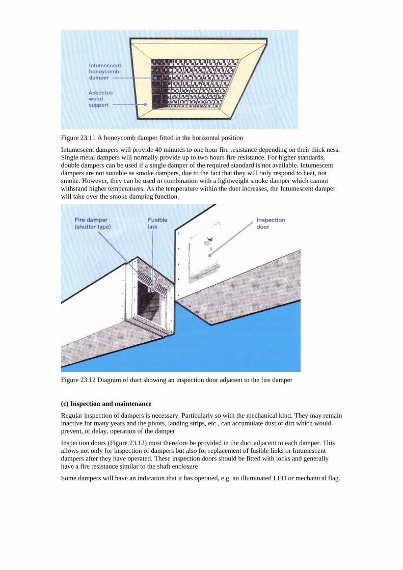
Figure 23.11 A honeycomb damper fitted in the horizontal position
Intumescent dampers will provide 40 minutes to one hour fire resistance depending on their thick ness. Single metal dampers will normally provide up to two hours fire resistance. For higher standards. double dampers can be used if a single damper of the required standard is not available. Intumescent dampers are not suitable as smoke dampers, due to the fact that they will only respond to heat, not smoke. However, they can be used in combination with a lightweight smoke damper which cannot withstand higher temperatures. As the temperature within the duet increases, the Intumescent damper will take over the smoke damping function.
Figure 23.12 Diagram of duct showing an inspection door adjacent to the fire damper
(c) Inspection and maintenance
Regular inspection of dampers is necessary. Particularly so with the mechanical kind. They may remain inactive for many years and the pivots, landing strips, etc., can accumulate dust or dirt which would prevent, or delay, operation of the damper
Inspection doors (Figure 23.12) must therefore be provided in the duct adjacent to each damper. This allows not only for inspection of dampers but also for replacement of fusible links or Intumescent dampers after they have operated. These inspection doors should be fitted with locks and generally have a fire resistance similar to the shaft enclosure
Some dampers will have an indication that it has operated, e.g. an illuminated LED or mechanical flag.
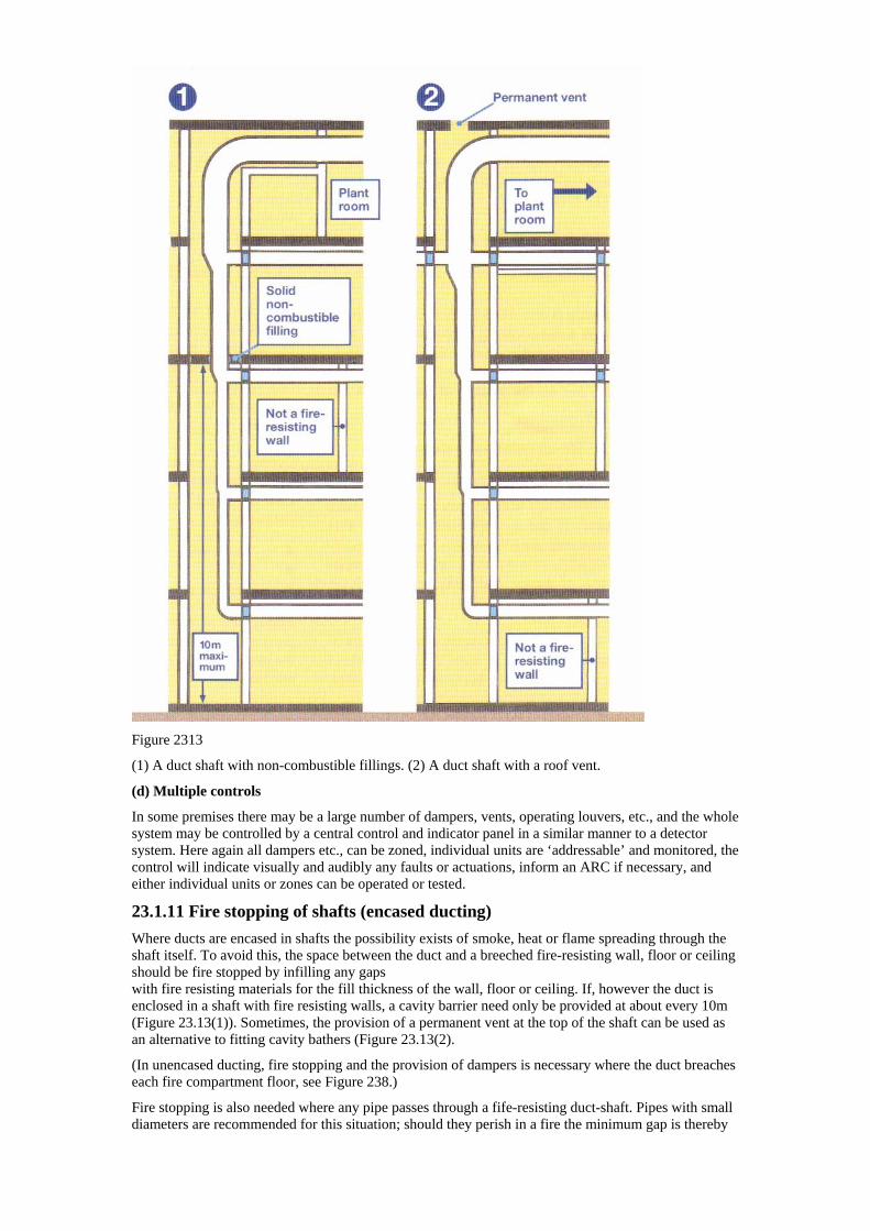
Figure 2313
(1) A duct shaft with non-combustible fillings. (2) A duct shaft with a roof vent.
(d) Multiple controls
In some premises there may be a large number of dampers, vents, operating louvers, etc., and the whole system may be controlled by a central control and indicator panel in a similar manner to a detector system. Here again all dampers etc., can be zoned, individual units are ‘addressable’ and monitored, the control will indicate visually and audibly any faults or actuations, inform an ARC if necessary, and either individual units or zones can be operated or tested.
23.1.11 Fire stopping of shafts (encased ducting) Where ducts are encased in shafts the possibility exists of smoke, heat or flame spreading through the shaft itself. To avoid this, the space between the duct and a breeched fire-resisting wall, floor or ceiling should be fire stopped by infilling any gaps with fire resisting materials for the fill thickness of the wall, floor or ceiling. If, however the duct is enclosed in a shaft with fire resisting walls, a cavity barrier need only be provided at about every 10m (Figure 23.13(1)). Sometimes, the provision of a permanent vent at the top of the shaft can be used as an alternative to fitting cavity bathers (Figure 23.13(2).
(In unencased ducting, fire stopping and the provision of dampers is necessary where the duct breaches each fire compartment floor, see Figure 238.)
Fire stopping is also needed where any pipe passes through a fife-resisting duct-shaft. Pipes with small diameters are recommended for this situation; should they perish in a fire the minimum gap is thereby
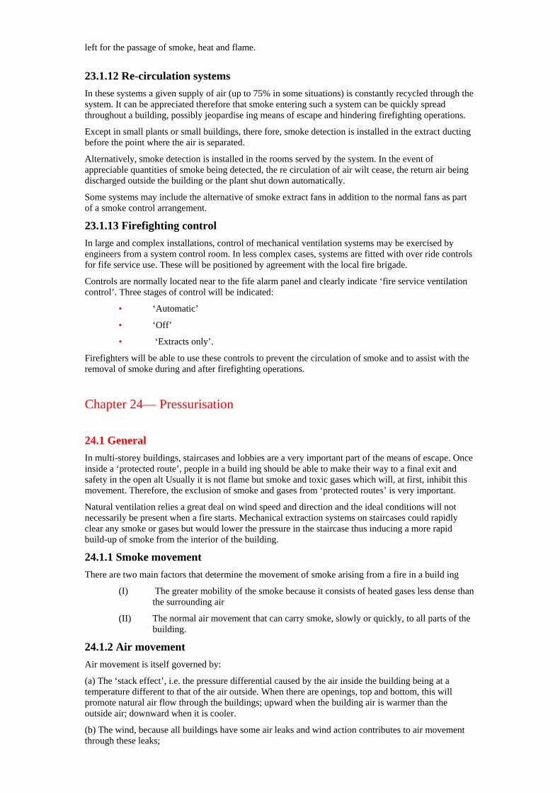
left for the passage of smoke, heat and flame.
23.1.12 Re-circulation systems In these systems a given supply of air (up to 75% in some situations) is constantly recycled through the system. It can be appreciated therefore that smoke entering such a system can be quickly spread throughout a building, possibly jeopardise ing means of escape and hindering firefighting operations.
Except in small plants or small buildings, there fore, smoke detection is installed in the extract ducting before the point where the air is separated.
Alternatively, smoke detection is installed in the rooms served by the system. In the event of appreciable quantities of smoke being detected, the re circulation of air wilt cease, the return air being discharged outside the building or the plant shut down automatically.
Some systems may include the alternative of smoke extract fans in addition to the normal fans as part of a smoke control arrangement.
23.1.13 Firefighting control In large and complex installations, control of mechanical ventilation systems may be exercised by engineers from a system control room. In less complex cases, systems are fitted with over ride controls for fife service use. These will be positioned by agreement with the local fire brigade.
Controls are normally located near to the fife alarm panel and clearly indicate ‘fire service ventilation control’. Three stages of control will be indicated:
• ‘Automatic’
• ‘Off’
• ‘Extracts only’.
Firefighters will be able to use these controls to prevent the circulation of smoke and to assist with the removal of smoke during and after firefighting operations.
Chapter 24— Pressurisation
24.1 General In multi-storey buildings, staircases and lobbies are a very important part of the means of escape. Once inside a ‘protected route’, people in a build ing should be able to make their way to a final exit and safety in the open alt Usually it is not flame but smoke and toxic gases which will, at first, inhibit this movement. Therefore, the exclusion of smoke and gases from ‘protected routes’ is very important.
Natural ventilation relies a great deal on wind speed and direction and the ideal conditions will not necessarily be present when a fire starts. Mechanical extraction systems on staircases could rapidly clear any smoke or gases but would lower the pressure in the staircase thus inducing a more rapid build-up of smoke from the interior of the building.
24.1.1 Smoke movement There are two main factors that determine the movement of smoke arising from a fire in a build ing
(I) The greater mobility of the smoke because it consists of heated gases less dense than the surrounding air
(II) The normal air movement that can carry smoke, slowly or quickly, to all parts of the building.
24.1.2 Air movement Air movement is itself governed by:
(a) The ‘stack effect’, i.e. the pressure differential caused by the air inside the building being at a temperature different to that of the air outside. When there are openings, top and bottom, this will promote natural air flow through the buildings; upward when the building air is warmer than the outside air; downward when it is cooler.
(b) The wind, because all buildings have some air leaks and wind action contributes to air movement through these leaks;
(c) Any mechanical ventilation system installed in the building.
24.1.3 Pressurisation Pressurisation provides a pressure difference which opposes, and overcomes, those generated by the factors which cause the movement of smoke. The use of pressurisation as a means of smoke control in atria has been discussed in Chapter 22.
Pressurisation can also be used to keep essential escape routes and firefighting access mutes clear of smoke for extended periods. Pressurisation systems designed for that purpose inject air into the protected escape routes, i.e. staircases, lobbies or corridors, which raises the pressure slightly above that of adjacent parts of the building. This prevents smoke and toxic gases from finding their way into the protected routes. A pressurisation system can be single or two-stage and used:
(a) Only in the event of a fire (either on automatic or manual operation).
(b) On full open whenever the building is occupied.
(c) At reduced capacity at normal times when the building is occupied with automatic boost to full operation in the event of fire.
The nature of the building and its occupancy and economics will dictate the system chosen.
24.1.4 Requirements of a pressurisation system The two basic considerations when designing a pressurisation system are:
The pressure required in the staircase, lobby or corridor; and the leakage paths.
(a) Pressure required
A pressurisation system, to be effective, must achieve a higher pressure than those developed by weather and fire conditions. The recommended level of pressurisation is about 45—50 Pa (Pascal) with all doors closed. This represents approximately 10 times the pressure normally developed in a fife and is four times the maximum pressure likely to be caused by adverse weather conditions.
The air flow required to achieve this pressure is independent of the volume of space to be pressurised. In deciding on the air flow required it is necessary to take the leakage paths into account.
(b) Leakage paths
Leakage paths are, generally, those minor gaps
around doors and windows which allow air to escape and they are a necessary part of a pressurisation scheme. Unless air is able to escape, the whole building will become pressurised and the necessary pressure differential (i.e. between the fife area and the protected route) will cease to exist. Leakage paths can be discussed in two stages:
• Initial leakage path
• Final leakage path.
• Initial leakage path
In most cases this will be past gaps around doors leading to individual rooms off the pressurised area or through lift doors (Figure 24.1) . It is obvious that badly fitting doors will create too large a leakage path and can unbalance a system; the maximum recommended gap is 3mm. However, in general, doors enclosing a pressurised space will also need to be fire resistant which should ensure a door that is close fitting to the frame.
In a fire situation, of course, people will have to exit through such doors. The momentary opening of doors does not seriously affect the pressurisation system and any pressure loss is quickly recovered when the doors close again. However, where the protected route is being used by people escaping or for firefighting access, it is likely that the final exit door will be open continuously. In these circum stances the pressurisation system should be capable of maintaining a pressure of not less than 10 Pa,
A pressure of 50 Pa will mean that a lithe extra pressure will be required to open a door leading to the pressurised area. This is sufficiently small to allow most people to open such doors and in all cases should not exceed 100N (Newton). However, any recommendation for the design of a pressurisation system should bear this fact in mind where children or the disabled are liable to be present.
(II) Final leakage path
As illustrated in Figure 24.1 this is usually through gaps in operable windows and through external doors and there will, generally, be sufficient leak age through these for the system to work. Where
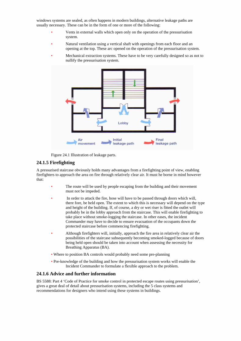
windows systems are sealed, as often happens in modern buildings, alternative leakage paths are usually necessary. These can be in the form of one or more of the following:
• Vents in external walls which open only on the operation of the pressurisation system.
• Natural ventilation using a vertical shaft with openings from each floor and an opening at the top. These arc opened on the operation of the pressurisation system.
• Mechanical extraction systems. These have to be very carefully designed so as not to nullify the pressurisation system.
Figure 24.1 Illustration of leakage parts.
24.1.5 Firefighting A pressurised staircase obviously holds many advantages from a firefighting point of view, enabling firefighters to approach the area on fire through relatively clear air. It must he borne in mind however that:
• The route will be used by people escaping from the building and their movement must not be impeded.
• In order to attack the fire, hose will have to be passed through doors which will, there fore, be held open. The extent to which this is necessary will depend on the type and height of the building. If, of course, a dry or wet riser is fitted the outlet will probably be in the lobby approach from the staircase. This will enable firefighting to take place without smoke-logging the staircase. In other eases, the incident Commander may have to decide to ensure evacuation of the occupants down the protected staircase before commencing firefighting.
• Although firefighters will, initially, approach the fire area in relatively clear air the possibilities of the staircase subsequently becoming smoked-logged because of doors being held open should be taken into account when assessing the necessity for Breathing Apparatus (BA).
• Where to position BA controls would probably need some pre-planning
• Pre-knowledge of the building and how the pressurisation system works will enable the Incident Commander to formulate a flexible approach to the problem.
24.1.6 Advice and further information BS 5588: Part 4 ‘Code of Practice for smoke control in protected escape routes using pressurisation’, gives a great deal of detail about pressurisation systems, including the 5 class systems and recommendations for designers who intend using these systems in buildings.