Embed Size (px)
Citation preview
Flexible Electronics for High-Density EMG Based Signal
Acquisition for Upper Limb Myoelectric Prosthesis Control
by
Damini Agarwal
A thesis submitted to Johns Hopkins University in conformity with the
requirements for the degree of Master of Science.
Baltimore, Maryland
May, 2017
© 2017 Damini Agarwal
All Rights Reserved
ii
ABSTRACT
The research detailed in this thesis is aimed at developing flexible electrodes for high-
density control of an upper limb myoelectric prosthesis. Different flexible dry
electrode materials (made from doped traditionally non-conductive substrates) were
used and compared to titanium (which is the industry standard for EMG electrodes).
We determined that conductivity measurements alone, (the current industry standard
for characterizing electrical properties of materials), are not sufficient due to their
complex impedance. We measured the skin electrode complex impedance and
relationship with signal to noise ratio (SNR) and settling time. We show that complex
skin electrode impedance is linearly related to the SNR of signals and that complex
skin electrode impedance better characterizes the electrical properties of doped,
traditionally non-conductive materials for physiological signal acquisition.
Next we constructed a flexible high-density array with 128- contact points arranged in
an 8 x 16 configuration to cover the entire residual limb. Myoelectric signals, and its
relationship to derived time domain features of all 128 channels were extracted and
represented as spatio-temporal values as 8 x 16 images to represent the muscle
activity map of the residual limb. Thus, a traditional signal-processing problem is
converted into an image processing problem. Obtaining High Density (HD) (128
channel) spatio-temporal information has significant merits which include: ability to
easily identify the optimum myoelectric recording sites on a residual limb, ability to
temporally study the onset and decline of a contraction, predicting the stage of
contraction and, finally, ability to implement proportional control and fine motor
myoelectric control.

iii
Thesis Committee Chair: Dr. Kevin Yarema
Thesis Project Adviser and Thesis Committee Member: Dr. Nitish Thakor
Thesis Committee Member: Dr. Sridevi Sarma

iv
PREFACE
ACKNOWLEGDEMENTS
I would like to thank my adviser, Dr. Nitish Thakor, for his mentorship, support and
advice that has enabled me to successfully pursue this research. I would also like to
thank him for always encouraging me to become a better version of myself and for
supporting all my academic and non-academic endeavors that allowed me to receive
numerous accolades. In addition, I would like to thank Dr. Rahul Kaliki for his
regular assistance and insights in this research as well as for being a key mentor in all
facets of my graduate school experience. Thank you also to Dr. Ananth Natarajan for
his guidance in both my research and entrepreneurial interests. I would also like to
thank Dr. Sridevi Sarma and Dr. Kevin Yarema for taking the time out to review and
discuss my work with me. I would like to extend a big thank you to my colleagues at
Infinite Biomedical Technologies, particularly Michelle Zwernemann for her help and
advice in all the development and testing associated with this research. I am also
grateful to all my colleagues in the lab, George Levay, Luke Osborn, Joseph
Betthauser, Ryan Smith, Guy Hotson, Juhi Baskar, Sapna Kumar and Geoffrey
Newman for their willingness to offer advice by drawing from their own research
experiences. I am honored to have had a chance to work alongside such great minds.
Finally, a warm thank you to all the undergraduate research volunteers, students,
prosthetists and patients with amputations who willingly offered their time, ideas and
feedback throughout this research project.

v
DEDICATION
This thesis is dedicated to my family, my wonderfully creative sister, my loving and
supportive parents, my encouraging uncle and my kind grandparents. Thank you for
being the strongest pillars of support that a person could wish for.
I would also like to dedicate this thesis to my teachers and my professors who have
always believed in me and have molded me into who I am today. Thank you for
teaching me that I am always more capable than what the world will let me believe.

vi
TABLE OF CONTENTS
CHAPTER 1 1-13
1. Chapter 1: Electrode Design for EMG Acquisition in Prosthesis 1
1.1. Types of Electrodes 1
1.2. Rigid Electrode Design and EMG for Myoelectric Control 7
1.3. Rigid Socket Design and its Effect on Electrodes 8
1.4. Use of Silicone Liners in Body-Powered Prosthesis 10
1.5. Location Specificity of Electronics in a Socket Affects EMG
Signal Quality 11
1.6. Potential Use of Silicone Liners in Myoelectric Prosthesis 13
CHAPTER 2 14-25
2. Chapter 2: Advances in Technology for Flexible Electronics:
Application to a Prosthetic Liner 14
2.1. Advances in Flexible Electronics 14
2.2. Materials for Flexible Electronics for EMG Acquisition 15
2.3. Flexible Electronics for Myoelectric Prosthesis 23
2.4. Summary 25
CHAPTER 3 26-51
3. Chapter 3: Developing Flexible Electronics and Methods
to Characterize Their Electrical Properties 26
3.1. Introduction to Skin Electrode Complex Impedance 26
3.2. Principle Behind Skin Electrode Impedance Measurement 27
3.3. Methods for Measuring Skin Impedance in Existing Electronics:

vii
Lead off Detection for Skin Impedance Measurement 28
3.5. Complex Skin Electrode Impedance Better Characterizes
the Electrical Properties of Doped, Traditionally Non-Conductive
Materials for Physiological Signal Acquisition 30
3.6. Summary 51
CHAPTER 4 52-87
4. Chapter 4: HD EMG for Myoelectric Control 52
4.1. Relevance of HD EMG to Myoelectric Control 52
4.2. Hardware Setup for HD EMG 55
4.3. HD EMG Muscle Activity Maps 59
4.4. Use of HD EMG in Myoelectric Prosthesis 71
4.5. Summary 87
CHAPTER 5 88-93
5. Chapter 5: Conclusion and Future Directions 88
5.1. Flexible Contacts 88
5.2. High Density EMG 90
6. APPENDIX 94-98
7. REFERENCES 99-120
8. BIOGRPAHICAL SKETCH 121

viii
LIST OF FIGURES
CHAPTER 1
1.1. Overview of current classification of electrodes for EMG signals
measurement 2
1.2. Wet Gel Electrode 3
1.3. Dry EMG electrodes 4
1.4. Comparison of initial electrode types 5
1.5. Intramuscular Needle Electrodes 6
1.6. Electrodes and Processor Attachment to Myoelectric Prosthesis
Socket 7
1.7. Silicone liners used in Upper Limb Prosthesis 10
1.8. Prosthesis Fitting Session 11
CHAPTER 2
2.1. Textile Electrodes 16
2.2. Textile Electrode with Conductive Traces 16
2.3. Spring Loaded Polymer Electrodes 18
2.4. Polymer based Electronic Tattoo 18
2.5. Conductive Silicone Electrode Contacts 19
2.6. Conductive Foam EEG Electrodes 20
2.7. Conductive Ink Printed Circuit 21
2.8. Conductive Yarn 22
CHAPTER 3
3.1. Flexible Contacts 33

ix
3.2. Electrical Modeling of Skin Electrode Interface 35
3.3.a. The apparatus for conductivity measurements 37
3.3.b. The contact material attachment to the IBT electrodes 37
3.3.c. The attachment of the electrode to the forearm 37
3.4.a. Conductivity of Materials vs. Time 43
3.4.b. SNR vs. Time 43
3.5.a: Signal from Titanium contact 44
3.5.b: Signal from Silicone (Doped with CNT) Contact 44
3.6.a: Complex Impedance vs. Time 46
3.6.b. Complex Impedance vs. Signal to Noise Ratio 46
3.7. Skin Electrode Complex Impedance vs. Signal to Noise Ratio 48
3.8.a. Signal to Noise Ratio vs. Time 50
3.8.b. Skin Electrode Complex Impedance vs. Time 50
CHAPTER 4
4.1. Vision of the HD EMG System with Flexible
Silicone Electrode Contacts 54
4.2. Hardware for HD EMG 56
4.3. FFT on Monopolar Signals 58
4.4. RMS and MAV Activity Maps 61
4.5. Muscle Activity Maps for Wrist Flexion and Wrist Extension 62
4.6. Different Finger Flexion Patterns 63
4.6. 32 Channel HD EMG Maps 66
4.7. 128 Channel HD EMG Maps 67
4.8. Muscle Activity Maps and Forearm Anatomy 69

x
4.9. KL curves for rest and thumb flexion. 73
4.10. KL curves for index flexion and middle flexion. 74
4.11. Onset of Contraction 77
4.12. Peak Contraction 78
4.13. Decline of Contraction 79
4.14. Liner detection algorithm 82
4.15. HD EMG maps for Myosite Location 86
6. APPENDIX
6.1. EMG pattern recognition performance based on feature relevancy 95

xi
LIST OF TABLES
CHAPTER 3
3.1. Epidermal and Sub-Epidermal Resistance, Capacitance
and Impedance 39
CHAPTER 4
4.1. Mean Squared Error between 5 Wrist Flexion Muscle Activity Maps 68
1
CHAPTER 1
1. Electrode Design for EMG Acquisition in Prosthesis
Electromyography is the process by which signals generated by muscle activation are
acquired by electrodes placed above muscle groups on both upper and lower limbs. It
is a powerful tool in myoelectric prostheses because the acquired muscle signals or
EMG from the residual limb of the patient are used for control of the artificial limb [1
- 3]. Electrode design, processing circuitry, algorithms as well as their integration are
all essential for robust control of a myoelectric prosthesis. This chapter provides an
overview of the electrodes that are used for EMG acquisition, their shortcomings and
potential improvements in their design.
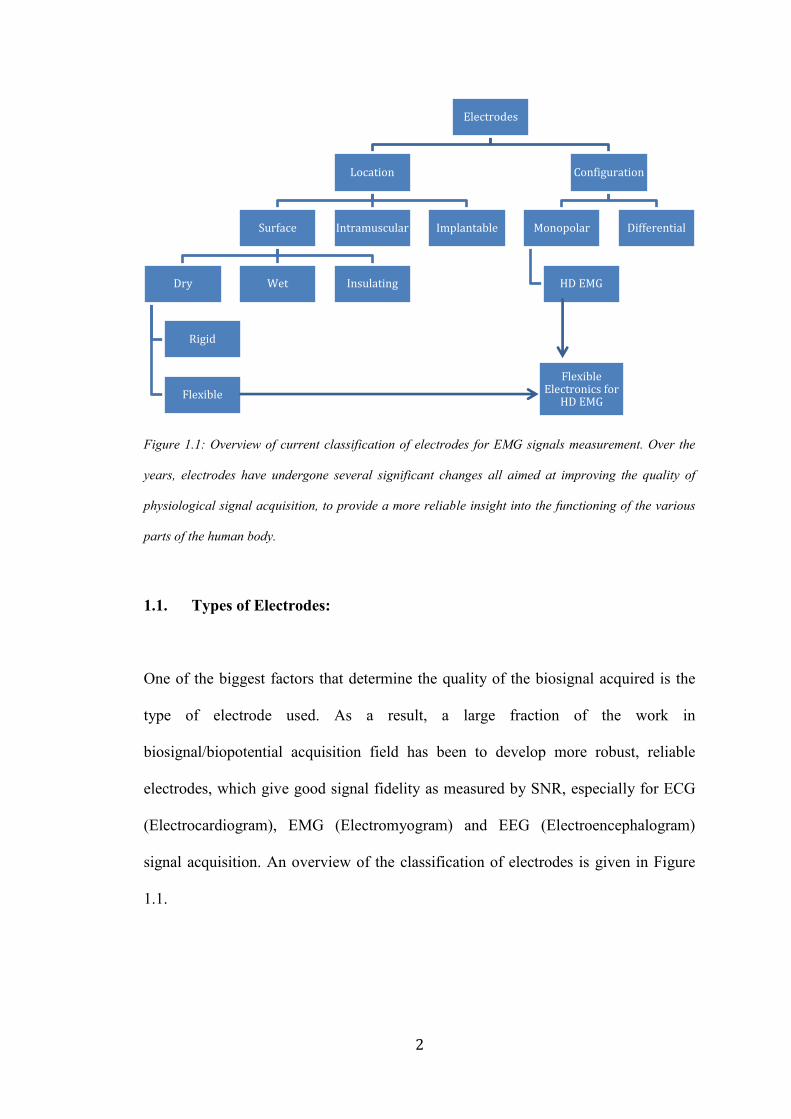
Figure 1 illustrates an overview of the chapter. Study of electrodes involves
experimental methods as well as design approaches. Experimental approaches
reviewed include noninvasive as well as invasive methods, configurations used
include monopolar and bipolar, and designs include dry, wet, insulating, and both
rigid and flexible. This research makes case for HD electrodes for EMG recordings
for upper limb prosthesis.
2
Figure 1.1: Overview of current classification of electrodes for EMG signals measurement. Over the
years, electrodes have undergone several significant changes all aimed at improving the quality of
physiological signal acquisition, to provide a more reliable insight into the functioning of the various
parts of the human body.
1.1. Types of Electrodes:
One of the biggest factors that determine the quality of the biosignal acquired is the
type of electrode used. As a result, a large fraction of the work in
biosignal/biopotential acquisition field has been to develop more robust, reliable
electrodes, which give good signal fidelity as measured by SNR, especially for ECG
(Electrocardiogram), EMG (Electromyogram) and EEG (Electroencephalogram)
signal acquisition. An overview of the classification of electrodes is given in Figure
1.1.
Electrodes
Location
Surface
Dry
Rigid
Flexible
Wet Insulating
Intramuscular Implantable
Configuration
Monopolar
HD EMG
Differential
Flexible Electronics for
HD EMG
3
1.1.1. Surface Electrodes
There are different kinds of electrodes for EMG and the technology has evolved
significantly over the years. Based on how they are placed, they are classified into
three types: surface electrodes for global EMG acquisition from the surface of the
skin, intramuscular electrodes
for localized EMG
acquisition using thin needle
electrodes from the interior of
muscles and implantable
electrodes for action potential
recordings from nerves. Of
the above, surface electrodes
are the industrial standard for
EMG electrodes for
prosthetic control. There are
various types of surface
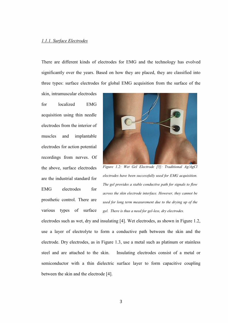
electrodes such as wet, dry and insulating [4]. Wet electrodes, as shown in Figure 1.2,
use a layer of electrolyte to form a conductive path between the skin and the
electrode. Dry electrodes, as in Figure 1.3, use a metal such as platinum or stainless
steel and are attached to the skin. Insulating electrodes consist of a metal or
semiconductor with a thin dielectric surface layer to form capacitive coupling
between the skin and the electrode [4].
Figure 1.2: Wet Gel Electrode [5]: Traditional Ag/AgCl
electrodes have been successfully used for EMG acquisition.
The gel provides a stable conductive path for signals to flow
across the skin electrode interface. However, they cannot be
used for long term measurement due to the drying up of the
gel. There is thus a need for gel-less, dry electrodes.

4
The most commonly used bioelectrode is the silver/silver chloride (Ag/AgCl) type,
which is more often found in a disposable form. While Ag/AgCl electrodes have
excellent properties such as low resistance and polarization potentials, they are also
more expensive and need gel
and good adhesive for
attachment to the skin. Other
problems, as that of greater
powerline interference, use of
electrolyte [6,7] amongst others
lead to the design of other
electrode types.
Similarly, dry and
insulating/active electrodes
have the advantage that they do
not need any electrolytic gel,
they come with their own host
of problems. Some of them are summarized in Figure 1.4 given below I don’t see
Fig. 1.4. Dry active electrodes are currently the industry standard for EMG
acquisition for prosthetic control. While myoelectric control of prosthesis is
constantly evolving from an algorithmic point of view, there has been very little
change in the actual rigid differential electrode design of the electrode itself. As a
result, the drawbacks associated with the same continue to be what they were over the
last several decades. This is evident from the following table. The instability of the
acquired signal, more specifically the quality of SNR resulting from motion
Figure 1.3: Dry EMG electrodes [8]. Dry EMG electrodes
are currently the industry standard for myoelectric
prosthesis, EMG acquisition. Numerous companies like
Ottobock, LTI, and CoAPT commercialize different dry
electrode technologies such as analog electrodes, digital
electrodes and remote electrodes.

5
artifactions and interference, presents the biggest challenge to reliable use of
prosthesis and some ways of overcoming it are mentioned in the next few sections.
Figure 1.4. Comparison of initial electrode types [4]. This table summarizes different materials that
have been used for creating electrodes over the years and highlights their advantages and
disadvantages. It is interesting to note that while most of these findings are several decades old, they
remain relavent even today due to the widespread use of some of these materials for signal acquisition.
Research efforts are now focused at developing alternate materials that overcome the limitations of
traditional dry electrode materials.
1.1.2. Intramuscular and Implantable Electrodes
One way of addressing the problem of unstable signals is to use intramuscular and
implantable electrodes. While surface electrodes are an easy way of acquiring global
muscular activation, they are not as useful when trying to understand the detailed

6
activation patterns of individual muscle groups. Intramuscular EMG was developed as
a solution for the same, using thin needle like electrodes as shown in Figure 1.5 that
are inserted into the muscle, so that localized muscle activation information can be
easily acquired [9]. Moreover, direct contact with the muscle ensures that motion
artifacts and other problems with surface EMG, does not affect this method as much.
While an intramuscular EMG can be more specific for capturing local muscle activity
than a surface EMG, it has numerous disadvantages for long-term recording. Besides
needing an invasive procedure, needle electrodes need to be placed at the exact same
location every single time and their insertion is a painful process. Inflammation,
infection movement and other problems also arise over time.
To overcome the disadvantages associated with intramuscular EMG, numerous
research efforts have focused on developing implantable electrodes that can be
surgically inserted under the skin, over a desired muscle group and anchored for long
Figure 1.5. Intramuscular Needle Electrodes [10]. Given above is picture of two different kinds of
needle electrodes used for intramuscular EMG acquisition. The area of insertion is usually numbed
with a local anesthetic before the needles are inserted into the muscle groups. Sometimes, multiple
tries are needed to get the electrodes in the correct spot. The hook at the end of the electrodes
attaches to the muscle fiber.

7
term EMG measurement [11]. The biggest challenges that need to be overcome
include biocompatibility of the materials, their flexibility, as well as wireless data and
power transfer to and from the implanted electrode [12-14].
1.2. Rigid Electrode Design and EMG for Myoelectric Control
While location of the electrodes is one of the reasons for signal instability, the bigger
contributor is the rigid electrode design. It is responsible in numerous ways for
biosignal infidelity. EMG electrodes are mounted on the inner surface of the rigid
prosthetic socket, good socket fit on the residual limb determines good skin-electrode
contact. See Figure 1.6 for the same.
This dependency on the socket gives rise to a large number of problems. Firstly, rigid
electrodes have a tendency to migrate under force and loading, and bad or irregular
contact with the skin degrades system performance [16]. This is further exacerbated
by the time required for skin-electrode chemical equilibrium, also called settling time,
to be established again before a stabilized signal can be obtained [17]. Moreover,
Figure 1.6. Electrodes and Processor Attachment to Myoelectric Prosthesis Socket [15]. The
electrodes are fabricated into the socket at myosite locations that give good EMG signal. They
connect into a processor that is usually mounted at the distal end of the prosthesis.
8
under excessive loading, electrode lift-off from the skin further leads to acquisition of
degraded EMG signals.
All of the above lead to two major disadvantages, not just from a signal acquisition
point of view but also from the perspective of signal use. With particular reference to
myoelectrically controlled upper limb prosthetics, bad EMG signal quality can
seriously undermine the efficacy of the algorithm used for limb control [18]. This
leads to longer limb response times, greater instability of hand and limb positions and
lack of dependency on the limb for everyday tasks.
Thus, there is an inherent need for redesigning electrodes for EMG acquisition in
prosthetics that affords signal fidelity across a variety of conditions. Most of the
major concerns include, motion artifact due to absence of electrolyte layer and greater
electrical interference [13]. In order to overcome these drawbacks, research is
currently focused on redesigning the electrode material substrate to make it more
flexible, conformal and less susceptible to rigidity induced motion artifact [14].
Moreover, advances in wireless data/power transfer in electrode design are also
making mounting easier [15] and eliminating the need for long cables, rigid supports
and other accessory components. The next generation of electrodes can pave the way
for use of implantable electrodes in myoelectric prosthesis control.
1.3. Rigid Socket Design and its Effect on Electrodes
Rigidity of electrodes is one of the reasons that contributes to bad signal acquisition,
particularly as a result of electrode lift off or motion. A rigid electrode is actually a

9
part of the much larger rigid socket design. Socket design for prosthesis has
undergone very little change since its conception in the early nineteen hundreds, and a
rigid socket can be attributed to many problems associated with current prosthetic
limbs [19]. These include bad fit leading to non-conformity to residual limb, bad
ventilation within the socket leading to sweating, and friction with the skin leading to
raw and damaged skin surface [20].
All of these issues directly or indirectly affect the functioning of electrodes as well.
Lack of ventilation leads to sweating and release of other bodily secretions, which not
only disturb the skin-electrode chemical equilibrium but also affect the path of
conductivity between the skin and electrode [21]. Moreover, changes in the
environment of the electrode skin interface due to the socket are not easy to predict
and thus lead to instability in final prosthetic limb control. Non-conformity of the
socket leads to electrode migration, lift off under loading and other associated
problems as mentioned earlier.
A rigid socket design also dampens the advantages of flexible electrodes if used in
conjunction with them. The conformity, which the flexible electrode could otherwise
provide is decreased and it is still susceptible to movement under loading and lack of
ventilation leading to conduction abnormalities.
Thus, one of the most comprehensive solutions to the current EMG signal acquisition
problem as well as for providing better fit and comfort to the user is the re-design of
the rigid socket to better interface with conformal electrodes and better fit the residual
human limb. One way of ensuring better attachment of electrodes is to integrate them
10
within silicone liners used with some prosthesis systems as mentioned in the next
section.
1.5. Use of Silicone Liners in Body-Powered Prosthesis
An alternative suspension technology developed over the last 20 years is the roll-on
gel liner which comfortably interfaces between the skin and the socket [36 – 39]. Gel
liners are typically formed from soft silicone gel or thermoplastic elastomer and are
usually cylindrical in shape with a rounded cap at the distal end. Images of a silicone
liner are given below in Figure 1.7.
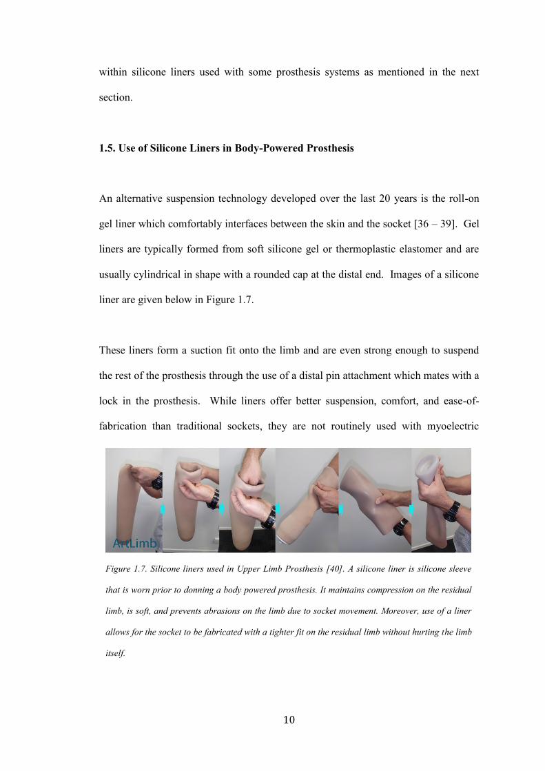
These liners form a suction fit onto the limb and are even strong enough to suspend
the rest of the prosthesis through the use of a distal pin attachment which mates with a
lock in the prosthesis. While liners offer better suspension, comfort, and ease-of-
fabrication than traditional sockets, they are not routinely used with myoelectric
Figure 1.7. Silicone liners used in Upper Limb Prosthesis [40]. A silicone liner is silicone sleeve
that is worn prior to donning a body powered prosthesis. It maintains compression on the residual
limb, is soft, and prevents abrasions on the limb due to socket movement. Moreover, use of a liner
allows for the socket to be fabricated with a tighter fit on the residual limb without hurting the limb
itself.
11
prostheses due to the difficulty of accommodating electrodes in the liner and aligning
the electrodes within the liner with the target EMG sites on the limb.
1.4. Location Specificity of Electronics Affects EMG Signal Quality
As per current industry protocol, for direct control systems and above-elbow pattern
recognition systems, prosthetists must accurately locate sites to place electrodes
within the socket such that there is minimal activity or “crosstalk” measured during
the contraction of the antagonist muscle [22]. If channels have too much crosstalk
during use, the prosthesis can become unresponsive and lead to abandonment. This
problem is compounded by the fact that clinicians do not have the necessary tools to
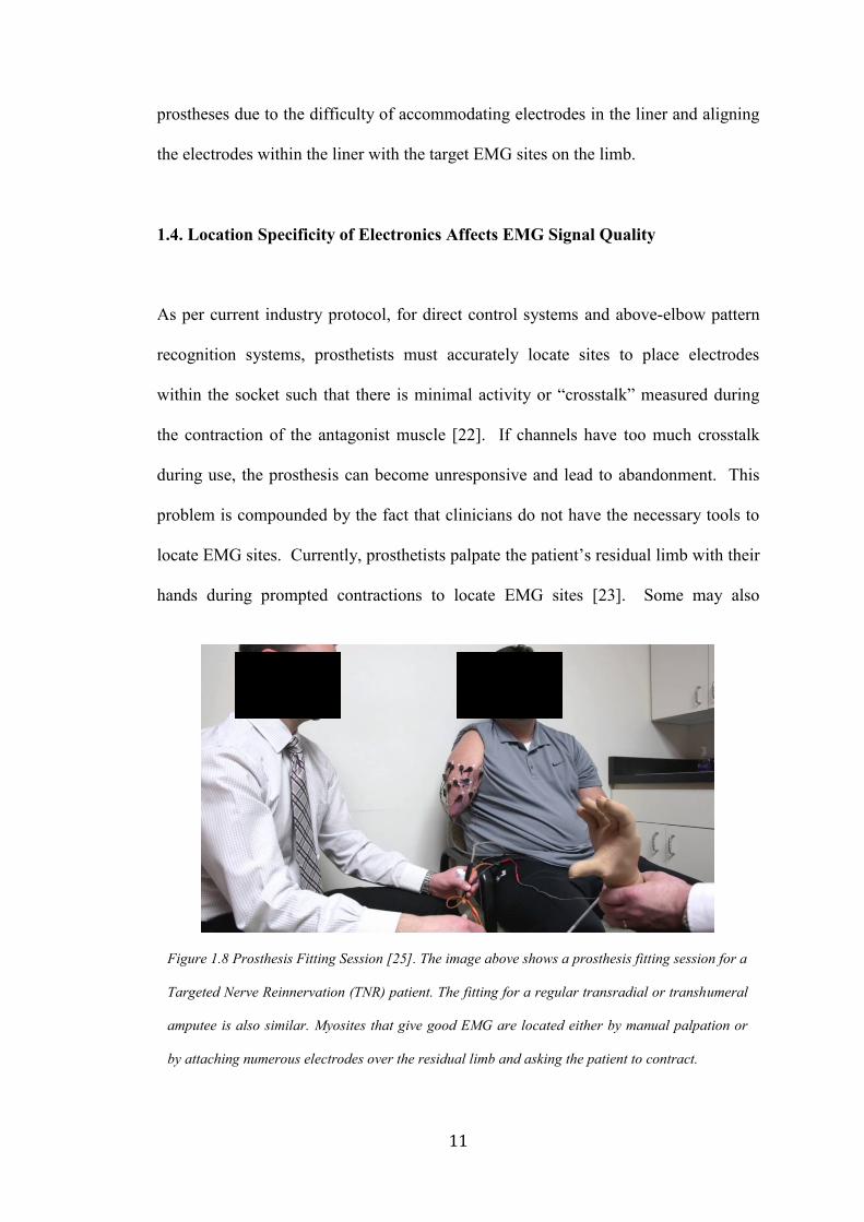
locate EMG sites. Currently, prosthetists palpate the patient’s residual limb with their
hands during prompted contractions to locate EMG sites [23]. Some may also
Figure 1.8 Prosthesis Fitting Session [25]. The image above shows a prosthesis fitting session for a
Targeted Nerve Reinnervation (TNR) patient. The fitting for a regular transradial or transhumeral
amputee is also similar. Myosites that give good EMG are located either by manual palpation or
by attaching numerous electrodes over the residual limb and asking the patient to contract.
12
manually move EMG sensors from place to place over residual limb to find areas of
maximal contraction [24] as shown in Figure 1.7.
However, both methods are not always accurate and can lead to poor site selection,
which can propagate through to the final construction of the prosthesis. Once a final
prosthesis is fabricated, moving electrodes to another site becomes very expensive
and time consuming, leading to frustration for the patient. This makes myoelectric
prosthesis a heavily specialized procedure as clinicians need to be experts in site
location. In fact, despite clinicians’ best-efforts, it is estimated [26] that one out of
five upper limb amputees eventually abandon their prostheses altogether, most
commonly citing a lack of functionality and difficulty of use [27].
In addition, the most significant challenges limiting pattern recognition algorithms
from achieving significant clinical utility are that they require exceedingly noise-free
EMG signals [27]–[30]. Signal noise can be attributed to a variety of sources
including displacement of the electrodes from their originally calibrated location [32]
and poor electrode-skin contact [33]. With regards to electrode displacement, one
study has shown that movement of 10 mm decreases decoding performance by an
average of 30% [34]. Such small displacements can happen every time a patient
dons (puts on) their prosthesis at the start of the day, thus requiring a minimum of
daily recalibration. However, shifts can also take place through the course of a day
requiring more frequent recalibration sessions, which can lead to user frustration.
13
1.6. Potential Use of Silicone Liners in Myoelectric Prosthesis
One way of solving the problem associated with rigid electrodes is to change the
material properties of the electrode itself and to embed it in a silicone liner in order to
make it pliable and conformal to the skin surface. This would have several advantages
including: It would provide better skin-electrode contact, prevent lift off under
loading conditions thus giving relatively stable signals, increase user comfort, allow
use of liners with myoelectric prosthesis. Flexible electrodes are being developed
using a variety of materials such as polymers [32], silicone with embedded
microelectronics [42], and textiles like conductive silk [43]. Moreover, development
in liquid gallium interconnects or meanders for creation of flexible circuits
interconnects could further support work in conformal electrode design [44] that
could ultimately be embedded in a silicone liner.
While use of flexible materials would make it possible to integrate electronics within
a liner, it still does not address the problem of location specificity. A possible way to
eliminate the need for location specificity is to replace the tradition 2-8 channel
electrode system with an HD array (greater than 8 contact sites) that covers the entire
limb of the patient. Algorithmic selection of the desired contacts for prosthesis control
could make flexible electronics in an HD configuration in a liner, an ideal solution for
the current drawbacks with myoelectric prosthesis.

14
CHAPTER 2
2. Chapter 2: Advances in Technology for Flexible Electronics: Application to a
Prosthetic Liner
Due to the limitations of traditional rigid electronics, numerous research groups and
companies are now focusing on developing flexible materials that can be used for
creation of electronics. The definition of electronics is evolving significantly from
PCBs (Printed Circuit Boards) and solid components to use of unconventional
materials and innovative technologies. This chapter highlights the different advances
in flexible electronics and how they may be used within a silicone liner for EMG
acquisition for myoelectric prosthesis control.
2.1. Advances in Flexible Electronics
2.1.1. Background
Health monitoring using wearable electronic sensors has recently come to the
forefront with its usefulness in applications for EMG based device control,
rehabilitation studies, cardiopulmonary monitoring and neurological studies. With
most biomedical industries moving closer to developing wearable devices, the rigidity
and bulkiness of current electronic hardware is proving to be a major disadvantage in
conformity to the human body as well as for fidelity of acquired biosignals [45]. As a
result, the need for flexible electronics has led to the development of numerous
materials that could potentially be used to form the contacts with the skin, convert
15
conventionally rigid electronic boards to innovative pliable ones, thereby enabling the
development of devices that are truly wearable in nature.
Based on current research in flexible electronics, we could classify the different types
of conformal electrodes based on the material and processes used to produce the
conductivity. Typically, based on material some broad classifications include textile
based, polymer based, silicone based, foam based and composite based flexible
electronics [52] for use in the passive parts of the circuit. Apart from developments in
conductive materials themselves, numerous research attempts are also focused on
creating flexible conductive interfaces using conductive inks and conductive tattoos.
This section provides an insight into different innovative conductive materials and
how they could be used for physiological signal acquisition. With a special reference
to prosthesis, all the above mentioned materials and processes could be potentially
used to integrate electronics with prosthetic liners made out of textile, silicone,
polymers as well as conductive tattoos.
2.2. Materials for Flexible Electronics for EMG Acquisition
2.2.1. Textile Based
Textile based electrodes are typically passive (do not require an active power supply)
in nature, and form the interface for signal acquisition from the body and for input to
the processing circuitry. They can be formed through numerous techniques and one
such method is the inclusion of the conductive fibers in the weave itself to form a
uniformly conductive textile patch [53]. While this method is useful in some ways, it
16
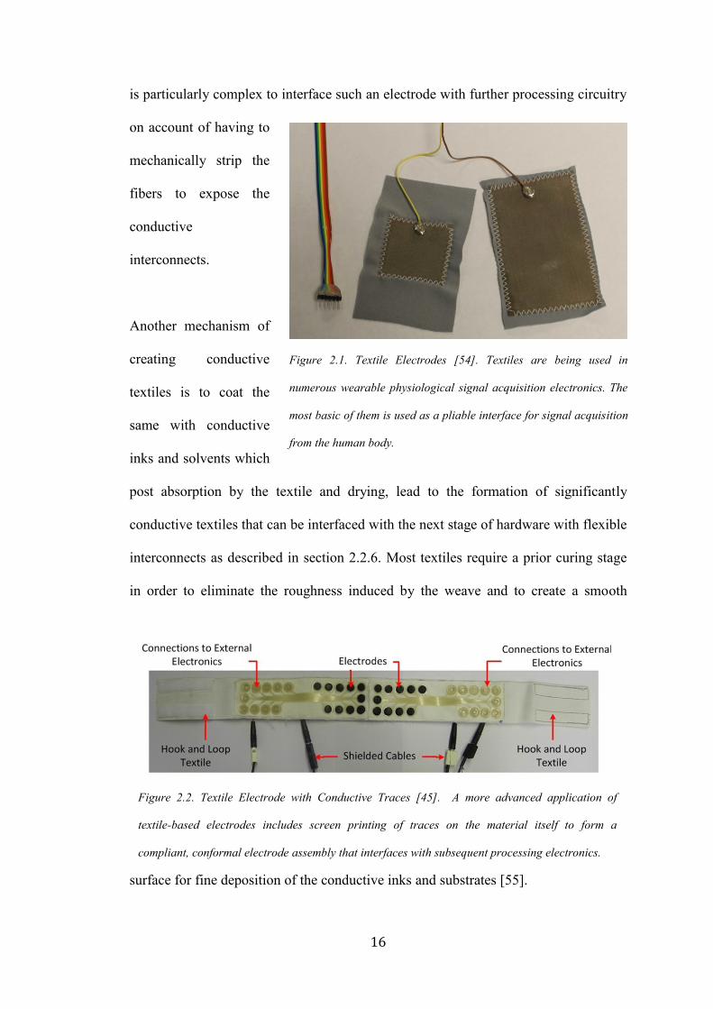
is particularly complex to interface such an electrode with further processing circuitry
on account of having to
mechanically strip the
fibers to expose the
conductive
interconnects.
Another mechanism of
creating conductive
textiles is to coat the
same with conductive
inks and solvents which
post absorption by the textile and drying, lead to the formation of significantly
conductive textiles that can be interfaced with the next stage of hardware with flexible
interconnects as described in section 2.2.6. Most textiles require a prior curing stage
in order to eliminate the roughness induced by the weave and to create a smooth
surface for fine deposition of the conductive inks and substrates [55].
Figure 2.1. Textile Electrodes [54]. Textiles are being used in
numerous wearable physiological signal acquisition electronics. The
most basic of them is used as a pliable interface for signal acquisition
from the human body.
Figure 2.2. Textile Electrode with Conductive Traces [45]. A more advanced application of
textile-based electrodes includes screen printing of traces on the material itself to form a
compliant, conformal electrode assembly that interfaces with subsequent processing electronics.
17
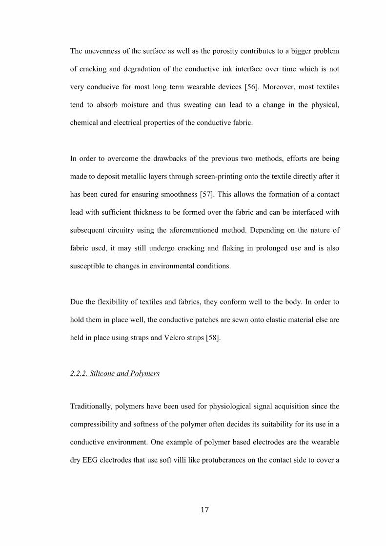
The unevenness of the surface as well as the porosity contributes to a bigger problem
of cracking and degradation of the conductive ink interface over time which is not
very conducive for most long term wearable devices [56]. Moreover, most textiles
tend to absorb moisture and thus sweating can lead to a change in the physical,
chemical and electrical properties of the conductive fabric.
In order to overcome the drawbacks of the previous two methods, efforts are being
made to deposit metallic layers through screen-printing onto the textile directly after it
has been cured for ensuring smoothness [57]. This allows the formation of a contact
lead with sufficient thickness to be formed over the fabric and can be interfaced with
subsequent circuitry using the aforementioned method. Depending on the nature of
fabric used, it may still undergo cracking and flaking in prolonged use and is also
susceptible to changes in environmental conditions.
Due the flexibility of textiles and fabrics, they conform well to the body. In order to
hold them in place well, the conductive patches are sewn onto elastic material else are
held in place using straps and Velcro strips [58].
2.2.2. Silicone and Polymers
Traditionally, polymers have been used for physiological signal acquisition since the
compressibility and softness of the polymer often decides its suitability for its use in a
conductive environment. One example of polymer based electrodes are the wearable
dry EEG electrodes that use soft villi like protuberances on the contact side to cover a

18
larger surface area of a
person’s scalp through hair
and at the same time provide
a little compressibility as well
[63].
More recently, efforts have
been made to use these
substrates to make thin
electronic patches. A key
advantage of polymer and
silicone based substrates over all other materials is their high conformity to bodily
Figure 2.3. Spring Loaded Polymer Electrodes [62]. These
electrodes are particularly useful for EEG acquisition as
they allow for good contact with the scalp, are compliant
and water/oil resistant.
Figure 2.4. Polymer based Electronic Tattoo [60]. The concept of tattoo based wearable
electronics is becoming sought after technology due to the stability is provides to the skin electrode
interface. However, long term use of these circuits is not feasible currently and remains the biggest
hurdle towards their commercial adoption.

19
surfaces on account of low Young’s Modulus. This makes them extremely useful for
forming the base substrate for flexible electrodes [59].
With regards to application of metallic layers to silicones, the tattoo technique is
extremely popular. This involves creation of a metalized layer of contact material and
then it’s transfer onto PDMS using an elastomeric stamp. A water soluble substrate is
used to help apply the PDMS with the metallic coating onto the skin [61]. The biggest
advantage of using silicone as a potential material is its hydrophobicity and relative
inertness in a salty environment thus making it invaluable for use within the
socket/liner where a humid, sweaty environment is a fairly common occurrence.
2.2.3. Conductive Silicone
Developed as a modification of the traditional
silicone material, conductive silicone is new
state of the art material and extremely useful.
It is formed by creating a solution of the
conductive material with silicone to disperse
the conductive particles through the bulk of
the base material. Curing brings about the
necessary stability in the structure. With
recent advancements, curing can be performed
at room temperature as well, making this
material compatible for application on other
Figure 2.5. Conductive Silicone
Electrode Contacts. The electrode
contacts in this picture are made of
conductive silicone so that they are
pliable, conformal and provide a more
stable interface to the skin.

20
heat sensitive materials. Some conductive particles include silver, gold, copper,
aluminum and graphite.
2.2.4. Conductive Foam
While the materials mentioned previously are extremely conformal in nature, they are
unable to provide a wide range of compressibility. This is especially important in the
creation of contacts for electrodes that require a certain degree of automatic
adjustments to changes in external pressure so that the electrode skin contact is well
maintained.
As a result, conductive foam that consists of conductive particles distributed across its
bulk provides excellent compressibility
across a wide range from 25x to more.
Moreover, compressibility also ensures
that the force that is applied to the user
in order to hold the electrode in place
does not lead to injury.
Conductive foam is usually used in
conjunction with conductive textiles to
form the even interface with the
surface for surface physiological signal
acquisition. An example is the
MINDO textile covered conductive
Figure 2.6. Conductive Foam EEG Electrodes [63 -
64]. These conductive foam electrodes are super
compliant and compressive thus eliminating the
problems that occur due to electrode liftoff. In case
of a lift off, the electrode simply decompressed and
a conductive path between the skin and electrode is
maintained.

21
foam electrodes for EEG acquisition. With minimal motion artefact and good
conductivity, the electrodes are suitable for any surface signal acquisition [64].
Conductive foam can be made out of different materials, such as copper, aluminum
and graphene. While electrical properties are similar, their use depends majorly on the
level of compression that can be achieved as well as compatibility with skin.
2.2.5. Creation of Conductive Interface using Conductive Inks
Apart from using the aforementioned materials for forming the base material for
creating the conductive interface, sometimes, additional metallic or conductive ink
layers are added to the these materials to form a better interface with the skin.
With metal being the top
choice for creating the
passive components of a
circuit such as the contact
leads and interconnects, a
lot of effort is currently
focused at developing an
easy and cost effective
mechanism for metal
deposition on a variety of
substrates like plastics, elastomers, papers and textiles. Innovative technologies like
PAMD (Polymer-Assisted Metal Deposition) allow fabrication of foldable, flexible,
stretchable and compressible wearable metal with high conductivity [67].
Figure 2.7. Conductive Ink Printed Circuit [65]. Conductive inks
are becoming extremely popular in creating flexible circuits on
materials that are pliable but cannot be doped.
Conductive traces made out of silver ink

22
While metal deposition techniques can often be cumbersome, conductive inks can be
applied much more easily through various methods such as screen printing, syringe
dispensing, dipping and spraying. The technique used is often dependent on the nature
of the base material as well as the nature of the contact that needs to be formed.
While most of the different techniques are extremely useful in application of inks for
short-term use, longer usage tends to cause cracks because of mechanical wear. This
makes the post processing methods used extremely important. Creation of a
nanoporous microstructure by post heat treatment after ink jet printing tends to create
more stable metallic layers than that of traditional evaporated films [66].
2.2.6. Flexible Conductive Interconnects
Innovative use of technologies ranging from development of conductive yarn as
Figure 2.8. Conductive Yarn [46]. This figure gives a detailed overview of the different fabrication
techniques and composition of conductive yarns. They form the basis for conductive textile
development, as well as are essential for creation of flexible electronic traces in textiles.

23
shown in Figure 2.1, [46] that is interwoven with metallic wires and connects to novel
methods of using liquid metal for interconnects in circuits is paving the way for
development of flexible device interfaces with the human body.
A key idea is to separate the fabrication of the electrode leads from interconnects
between the leads and subsequent parts of the circuitry. Thus, fabrication of a thin
conductive layer on a flexible substrate and specialized development of the
stretchable interconnects can help combine elements of conductivity and stretchability
which are otherwise difficult to incorporate together [50, 51].
2.3. Flexible Electronics for Myoelectric Prosthesis
One way of creating a robust EMG acquisition system that is compliant with the
upper limb, is to integrate a EMG acquisition flexible circuit within a silicone liner.
This flexible circuit would have 2 parts:
1. The electrode contacts that interface with the skin
2. The amplifier and processing circuitry
The design of this hardware will determine how it can be integrated within a liner.
Traditionally, EMG electrodes are used in a differential configuration with the
processing circuitry mounted as close to the contacts as possible to prevent
contamination by interfering signals. However, with appropriate shielding, the
contacts can be used in a remote configuration in which the electrode contacts are
located differently than the processing circuitry.

24
For a flexible circuit design that can be easily integrated into a liner, it would be
technically more feasible to integrate remote flexible contacts within the liner and
have them connected to processing circuitry at the distal end of the same. The same is
elaborated upon in the next few sections and chapters.
2.3.1. Electrode Contact Design
An ideal electrode contact would result in signals with high SNR, be compressible to
ensure contact even when the electrode shifts as well as have minimal settling time
when used with a prosthetic hand. Moreover, it would have to be such that it can be
easily integrated into a silicone liner. As a result, the most appropriate base material
for creating the electrode contacts would be conductive silicone. It has similar
material properties as non-conductive silicone due to which the two can be integrated
well. As a result, the electronics created can be integrated within existing silicone
liners with the electronics mounted at the distal end so that a remote electrode system
can be implemented.
This system could be supported further by the use of high-density electrode arrays for
EMG acquisition with flexible contacts for skin-electrode contact based channel
selection for use of EMG for prosthetic limb control.
The amplifier and processing circuitry design is strongly dependent on the
configuration of electrode contacts. While traditionally, a differential configuration is
used in electrodes for EMG acquisition, that may not be the best method when
integrating within in a liner due to the need for location specificity with respect to the
25
limb. It is nearly impossible to wear the liner the exact same way every single time
thus an arrangement of contacts in a HD location independent configuration may be
useful. Thus, use of HD of EMG electrodes on a flexible substrate may prove to be
beneficial in this regard.
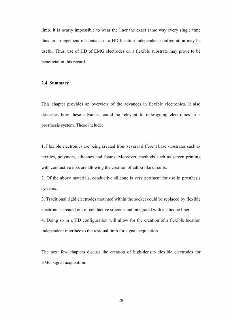
2.4. Summary
This chapter provides an overview of the advances in flexible electronics. It also
describes how these advances could be relevant to redesigning electronics in a
prosthesis system. These include:
1. Flexible electronics are being created from several different base substrates such as
textiles, polymers, silicones and foams. Moreover, methods such as screen-printing
with conductive inks are allowing the creation of tattoo like circuits.
2. Of the above materials, conductive silicone is very pertinent for use in prosthesis
systems.
3. Traditional rigid electrodes mounted within the socket could be replaced by flexible
electronics created out of conductive silicone and integrated with a silicone liner.
4. Doing so in a HD configuration will allow for the creation of a flexible location
independent interface to the residual limb for signal acquisition.
The next few chapters discuss the creation of high-density flexible electrodes for
EMG signal acquisition.
26
CHAPTER 3
3. Chapter 3: Developing Flexible Electronics and Methods to Characterize
Their Electrical Properties
Working with flexible materials for electronics development introduces numerous
challenges. These include establishing parameters for comparisons of electrical
properties of these new materials in a repeatable and universally replicable manner to
ensure that a standard is followed. Thus, the development of flexible electrodes using
doped traditionally non-conductive materials requires the design of new methods not
only for the creation of new materials, but also for the characterization of these
materials. This chapter highlights the ineffectiveness of traditional parameters used to
characterize conductive materials and establishes skin electrode complex impedance
as the better universal standard for characterizing new flexible materials for
physiological signal acquisition.
3.1. Introduction to Skin Electrode Complex Impedance
Skin-electrode impedance is the impedance of the skin and the electrode between the
electrode inputs. When the electrode is properly attached, the measured impedance is
low, and the input signal or injection current for measuring the skin electrode
impedance is extremely attenuated. When the electrode is not attached properly to the
skin (loosely contacting the skin or partially lifted off from the skin), the impedance is
very high and is reflected as such in the output signal [68].

27
Real time continuous monitoring of skin-electrode impedance measurement can
provide information about the nature of contact between the skin and the electrode.
This data can be used to determine whether the EMG signal acquired at a given
instance of time is of high fidelity or not and whether it should contribute to the
prosthetic limb control algorithm or not for greater stability and control. Impedance
measurements can help monitor bad contact between skin and electrode as well as can
be used to eliminate bad quality signals from inclusion in the algorithm for limb
control. While impedance monitoring for electrode lift off is not a permanent solution
to acquiring high quality signals, use of impedance to determine electrode lift off
conditions can limit the extent of instability in limb control.
3.2. Principle Behind Skin Electrode Impedance Measurement
Generally, the concept of measuring skin electrode impedance is accomplished by
inputting a known excitation current signal at a high frequency through one lead and
acquiring the signal after it has traversed through layers of electrode and skin at the
other lead [69].
The strength of the conductive pathway between the electrode and patient (or in other
words, skin electrode impedance) causes a proportional voltage drop across the two
leads, which after processing by the analog front end can be viewed digitally.
The measured output voltage when divided by the known injection current gives us
the skin electrode impedance at a given instance of time, real time.

28
Typical values while measuring skin electrode impedance [70]:
• Impedance : 1kΩ to 1MΩ
• Frequency of stimulation: 0 - 5 kHz (Depends on the AFE (Analog Front
End))
• Injected current: Few nA (Depends on the AFE used)
Skin electrode impedance is assumed to have dependency on numerous factors such
as:
• Skin properties of the user
• Contact area of the electrode
• Pressure on the electrode [71]
• Sweat/Bodily secretions of the user
3.3. Methods for Measuring Skin Impedance in Existing Electronics: Lead off
Detection for Skin Impedance Measurement
Most AFE systems have built in current injectors for measurement of skin-electrode
impedance to detect Lead Off. This can be done in multiple ways as listed below [72].
• Analog DC Lead Off - Using a simple dc current source or passive components
in a pull-up or pull-down resistor configuration are common methods for DC
lead-off detection. This method has multiple drawbacks. Firstly, it does not give
us an output with physical impedance values since the AFE has built in
comparators against which the measured value is compared. The output is in
terms of Lead On or Lead Off which is not useful for studying the intermediary
29
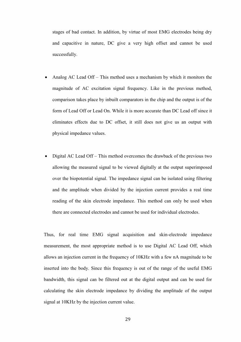
stages of bad contact. In addition, by virtue of most EMG electrodes being dry
and capacitive in nature, DC give a very high offset and cannot be used
successfully.
• Analog AC Lead Off – This method uses a mechanism by which it monitors the
magnitude of AC excitation signal frequency. Like in the previous method,
comparison takes place by inbuilt comparators in the chip and the output is of the
form of Lead Off or Lead On. While it is more accurate than DC Lead off since it
eliminates effects due to DC offset, it still does not give us an output with
physical impedance values.
• Digital AC Lead Off – This method overcomes the drawback of the previous two
allowing the measured signal to be viewed digitally at the output superimposed
over the biopotential signal. The impedance signal can be isolated using filtering
and the amplitude when divided by the injection current provides a real time
reading of the skin electrode impedance. This method can only be used when
there are connected electrodes and cannot be used for individual electrodes.
Thus, for real time EMG signal acquisition and skin-electrode impedance
measurement, the most appropriate method is to use Digital AC Lead Off, which
allows an injection current in the frequency of 10KHz with a few nA magnitude to be
inserted into the body. Since this frequency is out of the range of the useful EMG
bandwidth, this signal can be filtered out at the digital output and can be used for
calculating the skin electrode impedance by dividing the amplitude of the output
signal at 10KHz by the injection current value.
30
3.5. Complex Skin Electrode Impedance Better Characterizes the Electrical
Properties of Doped, Traditionally Non-Conductive Materials for Physiological
Signal Acquisition
Conventionally, for long term recording of EMG signals, such as in a prosthesis, dry
electrodes having bar or dome contacts made of titanium or stainless steel [73 - 74]
are used because their high conductivity as well as due to the usability of the EMG
signal acquired through them. Skin preparation [75] using alcohol swabs or CalStat
Skin preparation solution [127] is preferred to quickly establish equilibrium at the
electrode skin interface and to reduce the settling time.
Moreover, for acquiring usable EMG signals from the residual limb for long periods
of time and in order to ensure a tight fit, the electrodes are attached to the inside of a
prosthesis socket that is custom - designed for each user [76 – 77]. Often due to the
anatomy of the residual limb, the socket can move under loading conditions of the
arm which causes electrode migration and electrode lift off, thereby affecting signal
fidelity [28 - 78].
In order to overcome the limitations of current rigid electronic systems in prosthetics,
research is focused on developing flexible electronic solutions to the same. Electrode
contacts made out of compressible, flexible and doped polymers, silicones and textiles
as given in references [79 - 81] conform to the shape of the residual limb and form a
stable interface to the socket. However, the biggest problem in the comparison of
these new materials in their ability to be used for signal acquisition is that there is no
uniform metric that can be used to objectively quantify or predict the quality of signal
that can be acquired through the material by measuring a known electrical parameter.

31
Traditionally, conductivity was assumed to be the best measure of approximating the
quality of signal acquired through a material, since a high conductivity indicates a
good ability of the material to conduct signals and correlates to a high quality of
signal through a material [82 - 83]. Even today, most datasheets for materials (both
metals and doped substances) from commercial manufacturers have conductivity or
resistivity values as the metric to define electrical properties [84 – 87].
While this relationship works very well with purely resistive materials like metals that
have conventionally been used to develop electrode contacts, it becomes invalid when
working with materials that are primarily non-conductive and are made conductive
only through doping. This is because doped materials have a capacitive component in
addition to the resistive component that contributes to the nature of signal acquired
through that material which conductivity does not account for. Since conductivity
measurements do not provide an accurate representation of electrical properties of all
kinds of materials, many researchers use SNR or Signal to Noise Ratio [13– 88] of the
signal acquired as a means of quantifying and comparing the conductive properties of
different materials. The higher the SNR of the signal acquired through a given
material, the better the electrical properties of the material for signal acquisition.
However, the mechanism of SNR measurement is not always uniform and results
from different research groups cannot always be compared against each other. There
is thus a need for a more uniform and generic parameter for quantification of the
electrical properties of all kinds of electrode contact materials such as metals,
polymers, silicones and foams amongst others. Instead of looking purely at the
conductivity values, complex impedance is a better metric to quantify the electrical
32
properties of a material. Moreover, including the skin electrode impedance may be an
even better metric for comparison when studying materials used for making electrode
contacts since the composite measure provides the most accurate representation of
how the material interacts with the skin which subsequently governs the physiological
signal quality [89 - 91].
Therefore, apart from a need for flexible electrode contacts that match the electrical
properties of the skin better, there is also a need for a uniform parameter to
characterize the electrical properties of all kinds of materials used for making these
electrode contacts.
3.5.1. Methods
For this study, we created electrode contacts from a wide range of materials in order
to understand their interaction with the skin, determine the quality of signal through
them and find a universal way to electrically characterize them. The different
materials include: Anodized Titanium (industry standard for EMG electrodes for
prosthesis), conductive silicone doped with three different kinds of dopants in to
induce conductivity namely Carbon Nanotube (in three different concentrations –
WW46, WW45, WW44), Silver [87] (CSC), and Copper Nickel [84 – 85] (in two
different concentrations) (CSA and CSB), electrically conductive polyurethane foam
coated with copper and nickel [86], and conductive foam coated with a layer of
conductive silicone [86, 87]. The conductive silicones with silver and copper-nickel
dopants were commercially obtained from Silicone Solutions in uncured form and
were cured in-house.

33
The conductive foam was obtained from Holland Shielding Systems, BV,
Netherlands. Our team collaborators fabricated the silicones with Carbon Nanotube
(CNT) doping.
The electrode contacts were developed in two sizes: 10mm (L) x 6.5mm (B) x 6.5mm
(H) and 10mm (L) x 3.5mm (B) x 6.5mm(H) for attachment to the reference input and
differential signal inputs of the custom made active differential EMG Element
electrodes from Infinite Biomedical Technologies LLC. A sample of the contact is
shown in Figure 3.1
In addition, the electrical equivalent diagram of the dry electrode combination was
determined to model the skin electrode interface through passive components [64 -
Figure 3.1, Flexible Contacts. It represents the layout of each contact made out of metal, doped
silicone, conductive foam or a combination of foam and silicone. The electrode contacts were
developed in two sizes: 10mm (L) x 6.5mm (B) x 6.5mm (H) and 10mm (L) x 3.5mm (B) x
6.5mm(H) for attachment to the reference input and differential signal inputs of the custom made
active differential EMG Element electrodes from Infinite Biomedical Technologies LLC. In
addition, one contact of each type of material was also mounted on a plastic base with conductive
epoxy to allow easy attachment to subject forearms for impedance measurements.
34
92]. Unlike gel electrodes where the gel is purely resistive in nature, the dry materials
used in this study have a layer of air present between the skin and electrode interface
and they are comprised of a non-conductive matrix, which contributes to a capacitive
component in addition to a resistive component. It is modeled as CC and RC
respectively. The surface potential of the skin electrode interface is present as a DC
voltage. As per literature, its standard value is -39.6mV [70]. The epidermis and sub-
epidermal layers are also both resistive and capacitive due to the presence of the
Extracellular Fluid (ECF), cell membrane of cells and the Intracellular Fluid (ICF).
They are modeled as RE+SE and CE+SE, The deep tissue layers are modeled as
purely resistive in Nature and have a value of about 200 Ohms at frequencies below
10 kHz and a value of 120 Ohms at frequencies in the MHz range [70].
In order to determine a stable frequency for studying the skin electrode impedance
behavior of different materials, skin electrode impedance values were measured from
three sets of different materials placed in contact with the forearm of a single subject
at 1000 Hz (industry standard for impedance measurement for electrode lift off
detection) [72] and at 5000Hz (higher frequencies between 5KHz and 1 MHz ensure
that the impedance measured is independent of the shape and size of the material
used) [28]. The gathered data along with complex impedance values of the material
itself as well as the known constants of the skin electrode interface modeling (two
resistance in parallel with capacitance all in series with a resistance, as given in Fig.
3.2) [70] was then used to calculate the impedance values of the sub-dermal tissue
layers alone. Mathematically,
ZEpidermal+Sub-Epidermal =

35
ZSkin Electrode Interface – ZContact Material –RDeep Tissue (Eq.2.1)
Where ZSkin Electrode Interface is the Skin Electrode Complex Impedance measured
by placing the material on the skin and taking impedance reading of the entire
interface at both 5000Hz and 1000Hz
ZContact Material is the Complex Impedance measured by taking impedance readings
of the material alone at 5000Hz and 1000Hz
RDeep Tissue is 200 Ohms based on prior literature [70].
Figure 3.2. Electrical Modeling of Skin Electrode Interface. The diagram represents the electrical
equivalent diagram of the dry electrode skin combination. The dry materials used in this study have
layer of air present between the skin and electrode interface, which contributes to a capacitive
component in addition to a resistive component. The materials themselves have a resistive and
capacitive component. The surface potential of the skin electrode interface is present as a DC
voltage. The epidermis is also both resistive and capacitive due to the presence of conductive fluids
like sweat and non-conductive dry skin. The sub - dermal layers are modeled as purely resistive in
nature.

36
Four different measurements were made for each of the eight different materials for
five different healthy subjects (18 - 30 years) over 20-minute recording sessions for
each material, with data points gathered each minute. The study was conducted over a
20 minute interval since all the materials used in this study stabilized in their signal
quality within a 20 minute interval. This is consistent with literature on titanium and
stainless steel (industry standard), which stabilize within 10-15 minutes of being
attached to the skin [74]. If a material takes more than 20 minutes to reach electrical
stability, it is unsuitable for instantaneous electrophysiological measurements [134].
The different datasets gathered were: Conductivity, Complex Impedance, Skin
Electrode Complex Impedance and Signal to Noise Ratio (SNR) [93]. Conductivity
measurements were made by placing the electrode contact within a mechanical
contraption for maintaining good surface contact. Wires from the two plates of the
contraption in contact with the material were connected to a Fluke 15B F15B+
Professional Auto Range Digital Multimeter Tester and the DC resistance was
recorded. Each contact was measured with a pair of calipers and the dimensions were
recorded.
The resistivity of the material was calculated by:
ρ=R*l/A (Eq.2.2)
where ρ is the resistivity of the material, R is the resistance measured from the
multimeter, A is the area of cross section of the material touching the plates and l is
the height of the material between the two plates.
The conductivity values were determined through:
κ=1/ρ (Eq. 2.3)
where κ is the conductivity and ρ is the resistivity calculated in Equation 2.2.

37
Similarly, the Complex Impedance (CI) values were calculated by placing the
electrode contact within a mechanical contraption for maintaining good surface
contact. However, wires from the two plates were connected to a different system.
The Intan RHD2000 system by Intan Technologies LLC [128] was used to make
electrode impedance measurements. This processor and amplifier board system
injects a known current of 5 nA into the contact and measures the voltage developed
across the material. The known current magnitude and the measured voltage is then
used to mathematically compute the complex impedance.
One of the wires from the mechanical contraption was connected to an amplifier input
channel and the other was connected to ground to make this measurement.
Figure 3.3.a. The apparatus for conductivity measurements. The material is placed between the
metal plates of the mechanical contraption, which is held at a constant spacing using spacers. The
wires leading out of the measurement rig are connected to the digital multimeter and DC resistance
is measured. The same is used with the Intan system for complex impedance measurements.
Figure 3.3.b. The contact material attachment to the IBT electrodes is shown. The metal, conductive
silicone or foam material is mounted on the outer enclosure such that when the electrode board is
encased within the enclosure, a continuous path of conduction is formed between the material to be
tested and the spring contacts on the electrode board.
Figure. 3.3.c. The attachment of the electrode to the forearm is demonstrated. The electrode is
placed about 2 inches distal to the elbow at the point of maximum muscle activity for a hand flexion.
38
Skin electrode complex impedance measurements were made by attaching each
contact to the subject’s forearm, 2 inches distal to the elbow and connecting it to an
amplifier channel in the Intan system [128] with a separate ground electrode
connected to the epicondyle on the elbow of each individual.
For SNR measurements, the contact material was used in conjunction with an Infinite
Biomedical Technologies Element electrode [129] used in commercial prosthesis for
EMG measurements. The electrode is a dry differential electrode with titanium
contacts that uses the Texas Instruments ADS1291 as the amplifier with a
programmable gain. The experimental construction of SNR measurements is
described in Figure 3.3. The electrode was placed over the flexor muscle,
approximately 5 centimeters distal from the elbow and secured with an elastic cuff.
The subject was asked to contract the flexor muscle every minute and the SNR ratio
of each EMG contraction signal was calculated using a custom MATLAB function
and noted. The acquired signal was analyzed for SNR in MATLAB using a custom
written function calculates the ratio of the RMS of signal to the RMS of noise in a
specific window period.
Mathematically:
SNR=(RMS of desired signal)/(RMS of baseline noise) (Eq 2.4)
In addition, for all SNR measurements, the location with the highest signal amplitude
was located using a traditional dry EMG electrode and the same location was used for
all subsequent electrode placements for different contact materials. All the data

39
acquisition from the subjects was performed without any skin preparation in order to
study the natural behavior of the material when put in contact with skin.
3.5.2. Results and Discussion
3.5.2.1. Stability of Impedance Data at 5000 Hz as compared to 1000 Hz
At a frequency of 1000 Hz, the standard deviation in the resistance of the sub-dermal
layers was in the range of of 160 kOhms and the standard deviation in capacitance
was in the order of 8 nF for all materials. However, at a frequency of 5000 Hz, the
standard deviation in the resistance of the sub-dermal layers was in the range of 2
kOhms and the standard deviation in capacitance was ~5 nF for all materials. Overall,
the impedance measured at 1000 Hz varies very highly by almost 75 kOhms,
however, the impedance at 5000 Hz follows a very stable trend with limited variation
and has a standard deviation of only 0.6 kOhms. The reason for the stark difference
between impedance measurements at 1000 Hz vs 5000 Hz could be attributed to how
the current and frequency interact with the biological tissue layers. At low
frequencies, <5 KHz, the current cannot penetrate through the cell membrane and
hence most of the current travels through Extracellular Fluid (ECF). At high
frequencies, since the current is able to penetrate through the cell membrane, it travels
through Intracellular Fluid (ICF) in addition to the ECF [121].
As per our data, the average capacitance at 5000 Hz is ~18 nF while that at 1000 Hz is
~8 nF. Measuring a higher capacitance indicates that part of the current is flowing
through the ICF after penetrating the cell membrane which contributes to the
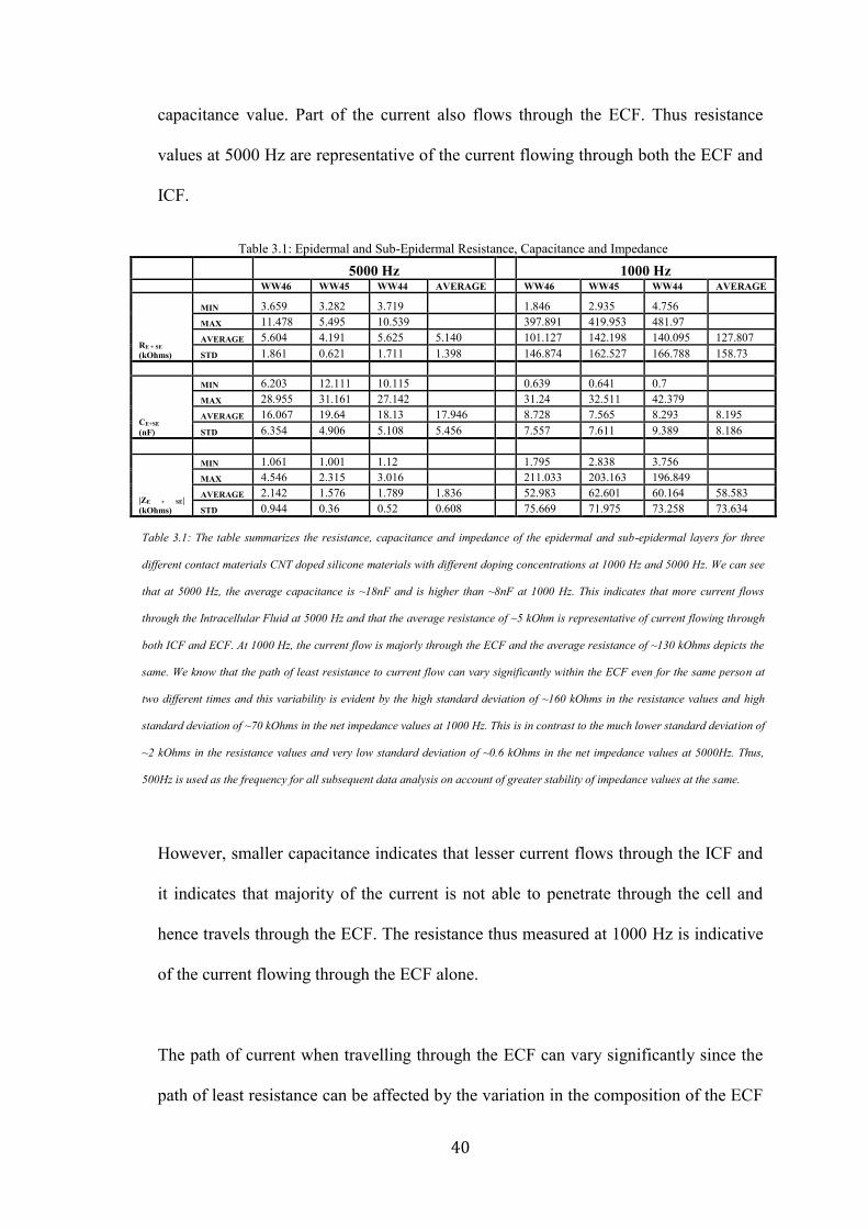
40
capacitance value. Part of the current also flows through the ECF. Thus resistance
values at 5000 Hz are representative of the current flowing through both the ECF and
ICF.
However, smaller capacitance indicates that lesser current flows through the ICF and
it indicates that majority of the current is not able to penetrate through the cell and
hence travels through the ECF. The resistance thus measured at 1000 Hz is indicative
of the current flowing through the ECF alone.
The path of current when travelling through the ECF can vary significantly since the
path of least resistance can be affected by the variation in the composition of the ECF
Table 3.1: Epidermal and Sub-Epidermal Resistance, Capacitance and Impedance
5000 Hz
1000 Hz
WW46 WW45 WW44 AVERAGE
WW46 WW45 WW44 AVERAGE
RE + SE
(kOhms)
MIN 3.659 3.282 3.719
1.846 2.935 4.756
MAX 11.478 5.495 10.539
397.891 419.953 481.97
AVERAGE 5.604 4.191 5.625 5.140
101.127 142.198 140.095 127.807
STD 1.861 0.621 1.711 1.398
146.874 162.527 166.788 158.73
CE+SE
(nF)
MIN 6.203 12.111 10.115
0.639 0.641 0.7 MAX 28.955 31.161 27.142
31.24 32.511 42.379
AVERAGE 16.067 19.64 18.13 17.946
8.728 7.565 8.293 8.195
STD 6.354 4.906 5.108 5.456
7.557 7.611 9.389 8.186
|ZE + SE|
(kOhms)
MIN 1.061 1.001 1.12
1.795 2.838 3.756 MAX 4.546 2.315 3.016
211.033 203.163 196.849
AVERAGE 2.142 1.576 1.789 1.836
52.983 62.601 60.164 58.583
STD 0.944 0.36 0.52 0.608
75.669 71.975 73.258 73.634
Table 3.1: The table summarizes the resistance, capacitance and impedance of the epidermal and sub-epidermal layers for three
different contact materials CNT doped silicone materials with different doping concentrations at 1000 Hz and 5000 Hz. We can see
that at 5000 Hz, the average capacitance is ~18nF and is higher than ~8nF at 1000 Hz. This indicates that more current flows
through the Intracellular Fluid at 5000 Hz and that the average resistance of ~5 kOhm is representative of current flowing through
both ICF and ECF. At 1000 Hz, the current flow is majorly through the ECF and the average resistance of ~130 kOhms depicts the
same. We know that the path of least resistance to current flow can vary significantly within the ECF even for the same person at
two different times and this variability is evident by the high standard deviation of ~160 kOhms in the resistance values and high
standard deviation of ~70 kOhms in the net impedance values at 1000 Hz. This is in contrast to the much lower standard deviation of
~2 kOhms in the resistance values and very low standard deviation of ~0.6 kOhms in the net impedance values at 5000Hz. Thus,
500Hz is used as the frequency for all subsequent data analysis on account of greater stability of impedance values at the same.
41
as well as arrangement of the cells inside it, as a result of which, every measurement
of resistance as well as capacitance, which is also dependent of the path length varies
more at lower frequencies [122, 123, 124, 125].
This makes measurements at 1000 Hz highly variable and unsuitable for studying the
relationship of impedance with other parameters. Thus due to the stability of
impedance values at 5000 Hz, it was used as the frequency to study the relationship of
impedance with respect to parameters such as time and SNR in the following sections.
Using 5000 Hz has other advantages which include minimal interference from motion
artefact, lack of dependence on shape and size of contact [94] as well as minimal
effect of stray muscle contractions (EMG signals lie in the 10 – 500 Hz range) [74]
which ensures that the measurements quantify the electrical properties of the skin
electrode interface alone.
3.5.2.2. Conductivity Variation for Long Term Measurement and Comparison with
SNR
A standard parameter for characterizing the electrical properties of a material,
specially its ability to conduct, is conductivity. The inverse of resistivity, conductivity
is a constant for a given material and for purely resistive materials like metals, and is
the best parameter for characterizing the nature of signal one may acquire out of
purely resistive materials.
42
Three resistance readings for each sample of material were made and were averaged
to calculate the resistivity and conductivity of the material. Data from four samples of
the same material were averaged to determine the bulk conductivity of the material.
However, based on the tests with samples of materials like conductive silicone, which
are primarily non-conductive and capacitive and are made conductive through doping,
it was seen that the conductivity measurements do not account for the capacitive
components.
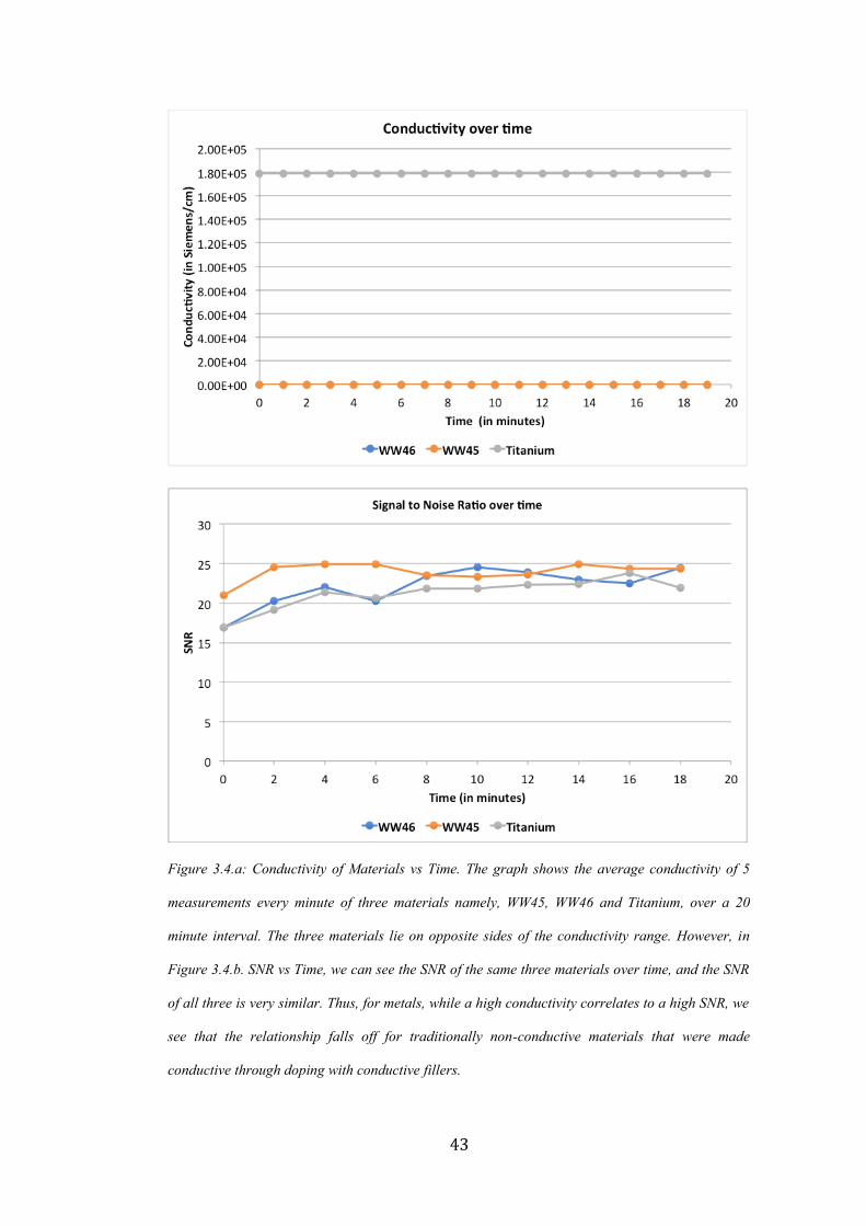
The graph given in Figure 3.4, demonstrates the order of materials based on their
conductivities. As seen, Titanium has conductivity in the order of [10]^6 Siemens/cm
whereas other materials such as WW46 and WW45 are much lower at a few 100
Siemens/cm. Based on these measurements, one would traditionally assume that
WW46 and WW45 would give significantly poor EMG signals if used as electrode
contacts. However, if we study the SNR of these materials over time as in Figure 3.5,
not only do we see that WW46 and WW45 give a signal with SNR that is definitely
usable for prosthesis control, they are almost identical to Titanium in terms of
baseline noise and amplitude of contractions if not better than Titanium at times. The
same was observed across all subjects, thus indicating, that conductivity may not be
the most comprehensive method for characterizing materials for physiological signal
control.
43
Figure 3.4.a: Conductivity of Materials vs Time. The graph shows the average conductivity of 5
measurements every minute of three materials namely, WW45, WW46 and Titanium, over a 20
minute interval. The three materials lie on opposite sides of the conductivity range. However, in
Figure 3.4.b. SNR vs Time, we can see the SNR of the same three materials over time, and the SNR
of all three is very similar. Thus, for metals, while a high conductivity correlates to a high SNR, we
see that the relationship falls off for traditionally non-conductive materials that were made
conductive through doping with conductive fillers.

44
Figure 3.5.a: Signal from Titanium contact, Figure 3.5.b: Signal from Silicone (Doped with
CNT) Contact. Comparison of both signals shows that they are comparable both visually and
computationally using SNR as a metric. The peak amplitude of the EMG signal during a
contraction is almost identical, if not better in the silicone sample. If the signal quality was
estimated based purely on the conductivity values, the two materials would not have been
identified as equally good for physiological signal acquisition.
45
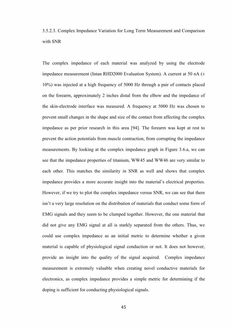
3.5.2.3. Complex Impedance Variation for Long Term Measurement and Comparison
with SNR
The complex impedance of each material was analyzed by using the electrode
impedance measurement (Intan RHD2000 Evaluation System). A current at 50 nA (±
10%) was injected at a high frequency of 5000 Hz through a pair of contacts placed
on the forearm, approximately 2 inches distal from the elbow and the impedance of
the skin-electrode interface was measured. A frequency at 5000 Hz was chosen to
prevent small changes in the shape and size of the contact from affecting the complex
impedance as per prior research in this area [94]. The forearm was kept at rest to
prevent the action potentials from muscle contraction, from corrupting the impedance
measurements. By looking at the complex impedance graph in Figure 3.6.a, we can
see that the impedance properties of titanium, WW45 and WW46 are very similar to
each other. This matches the similarity in SNR as well and shows that complex
impedance provides a more accurate insight into the material’s electrical properties.
However, if we try to plot the complex impedance versus SNR, we can see that there
isn’t a very large resolution on the distribution of materials that conduct some form of
EMG signals and they seem to be clumped together. However, the one material that
did not give any EMG signal at all is starkly separated from the others. Thus, we
could use complex impedance as an initial metric to determine whether a given
material is capable of physiological signal conduction or not. It does not however,
provide an insight into the quality of the signal acquired. Complex impedance
measurement is extremely valuable when creating novel conductive materials for
electronics, as complex impedance provides a simple metric for determining if the
doping is sufficient for conducting physiological signals.

46
Figure 3.6.a: Complex Impedance over time, Figure 3.6.b. Complex Impedance versus Signal to
Noise Ratio. As is evident from Fig. 3.6.a, the complex impedance curves of the three materials
shows an increased similarity to the SNR graph in Fig 3.4.b. They separate out at levels in the
complex impedance graph, proportionally inverse to their arrangement in the SNR graph. Thus,
complex impedance may characterize these materials better. However, when the complex
impedance of a diverse set of traditionally non-conductive materials was plotted against the SNR,
the graph did not provide much information on the nature of relationship between the two apart
form a stark clustering in materials that did conduct EMG signal in one part of the graph, with
complete separation from materials that did not conduct EMG signal at all.

47
3.5.2.4. Skin Electrode Complex Impedance Variation for Long Term Measurement
and Comparison with SNR
In order to quantify the quality of signal acquired through the electrode contacts by
using electrical measurement, Skin Electrode Complex Impedance (SECI)
measurements were made by placing the material on a human forearm and measuring
the impedance of the interface. SECI thus allows us to quantify the behavior of the
material when put in contact with skin. Measurements were again made at 5000 Hz
to eliminate the effects of difference in shape and size of the contact and the interface.
Based on the graph given below in Figure 3.8, it was noted that the SNR variations
were material dependent, while some had stable SNR values from the start of the data
gathering session, other took time to stabilize and reach their peak value. This is
similar to the SECI curves in which the materials that had stable SNR also had stable
SECI values. For materials in which the SNR increased over time until the values
reached stability, the SECI correspondingly decreased over time until it reached a
stable value.
Intuitively, we can see a relationship between SECI and SNR such that when the
SECI decreases, the SNR increases. A decrease in SECI results in lesser impedance to
ionic current flow across the skin electrode interface thereby increasing the amplitude
of the signal measured and thus improving the SNR. When SECI is plotted against
SNR for all the different materials, we can see a linear relationship between the two.
This linear relationship provides an insight into the nature of physiological signal
obtained through a novel doped conductive material.
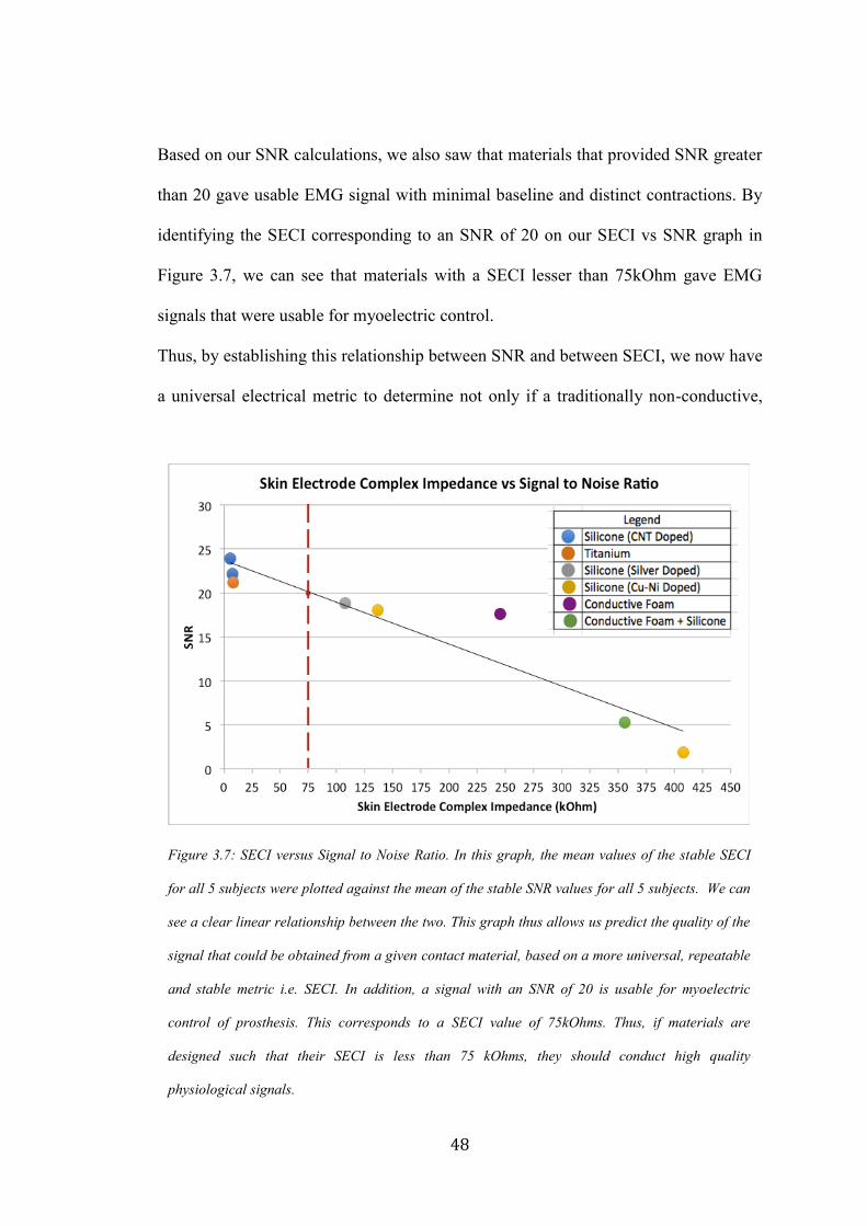
48
Based on our SNR calculations, we also saw that materials that provided SNR greater
than 20 gave usable EMG signal with minimal baseline and distinct contractions. By
identifying the SECI corresponding to an SNR of 20 on our SECI vs SNR graph in
Figure 3.7, we can see that materials with a SECI lesser than 75kOhm gave EMG
signals that were usable for myoelectric control.
Thus, by establishing this relationship between SNR and between SECI, we now have
a universal electrical metric to determine not only if a traditionally non-conductive,
Figure 3.7: SECI versus Signal to Noise Ratio. In this graph, the mean values of the stable SECI
for all 5 subjects were plotted against the mean of the stable SNR values for all 5 subjects. We can
see a clear linear relationship between the two. This graph thus allows us predict the quality of the
signal that could be obtained from a given contact material, based on a more universal, repeatable
and stable metric i.e. SECI. In addition, a signal with an SNR of 20 is usable for myoelectric
control of prosthesis. This corresponds to a SECI value of 75kOhms. Thus, if materials are
designed such that their SECI is less than 75 kOhms, they should conduct high quality
physiological signals.
49
doped material is suitable for physiological signal acquisition but also enables us to
predict the quality of signal coming from it.
3.5.2.4. Comparison of Settling Time of Different Materials
Another interesting observation from this study is the effect of the skin electrode
complex impedance of materials on their settling time. Typically, the human skin has
complex impedance in the order of a few MOhms, while materials like metals have
very low impedances in the order of a few Ohms. When metal contacts such as those
made out of titanium are used for signal acquisition, it takes several minutes for the
signal baseline to reduce to minimum and EMG amplitude to reach maxima. This
could be attributed to the process of ionic equilibrium at the skin electrode interface,
which takes time if the two materials have significantly different impedances.
When we look at the SECI and SNR graphs of the different materials over time (Fig.
3.8), we can see that materials like WW45 have very stable curves from the beginning
of data gathering itself, i.e. they require almost no time to settle. The SNR values are
high and the SECI values are intermediate to that of pure metal and skin, <75kOhms.
Thus, if new materials are developed such that the SECI is intermediate to that of
metal and skin, the material settles faster against the skin and will eliminate the need
for skin preparation.

50
Figure 3.8.a: Signal to Noise Ratio over time, Figure 3.8.b. SECI over time, as we can see from
the graphs, almost all the materials reach stable impedance and stable SNR values after a delay
of few minutes. However, when we look at WW45, the material corresponding to the curve at the
top of the SNR graph, we see that it “settles” very quickly, in under 2 minutes. Similarly, from
the SECI graph, we can see that WW45 has a stable impedance value from the very beginning.
This is very valuable in myoelectric control of prosthesis, since the faster a material reaches
stability with minimal intervention, the easier it is for the user to generate EMG signals to
control a prosthetic hand. If materials are designed keeping in mind impedance matching with
the skin and the processing electronics, it will do away with the need for skin preparation and
will make the electrode skin interface more stable.

51
3.6. Summary
1. Conductivity is not a good metric for characterizing doped traditionally non-
conductive materials for physiological signal acquisition.
2. Complex impedance is a good metric for determining if a given material is
capable of physiological signal conduction or not. However, it does not have a
linear relationship to SNR.
3. SECI is inversely linearly related to SNR, thus providing a uniform measurement
for comparing different materials and determining their ability to conduct
physiological signals. Materials with SECI less than 75 kOhm will provide
signals with high amplitude and low baseline noise.
4. There is a reduction in settling time by using materials with SECI intermediate to
that of metal and skin.

52
CHAPTER 4
4. Chapter 4: HD EMG for Myoelectric Control
Developments in the field of flexible electronics have been both innovative and rapid.
Flexible electronics, including sensors and circuits, offer many advantages outlined
earlier. The possibility of incorporating such an electronics technology within a
silicone liner for myoelectric signal acquisition use seems more appealing than rigid
electronics. We previously outlined that location dependency of electronics within a
liner as well the donning it in the exact way every single time is not practical. To
solve this problem, we developed an electronic solution of incorporating flexible
electronics within a liner. This is where HD EMG can provide a practical solution.
The ability to gather data from 128 different spots ensures that no matter how the liner
is worn, there will always be an electrode contact over the desired myoelectric signal
source (muscle group) to acquire EMG data from it. This chapter describes how HD
EMG can be used for more robust myoelectric signal acquisition as well as for the
advancement of myoelectric prosthesis.
4.1. Relevance of HD EMG to Myoelectric Control
Traditionally, EMG acquired through specific locations on the residual limb are used
for myoelectric prosthetic control. This requires the electrodes for EMG acquisition to
be attached to the exact same spots every single time, which is done by embedding
them in the custom designed rigid prosthetic socket that fits on the residual limb in a
single specific way. However, this method often affects signal fidelity due to
movement of the socket and electrodes under loading conditions as well as due to

53
electrode lift off. It can also cause abrasions and sores on the residual limb due to the
rigid nature of both the socket and the electrode. Discomfort and unreliable prosthesis
control is also one of the leading causes of prosthesis abandonment across the world.
Body powered prosthesis, face similar problems. In order to make the use of body
powered prosthesis more comfortable, a silicone liner that fits snugly on the residual
limb is worn prior to the socket and prosthetic arm. Not only does such a liner provide
a cushioning effect, it also helps in attaching the prosthesis with greater stability to the
residual limb.
Current myoelectric prosthesis system cannot use a silicone liner. This is because the
liner is non-conductive and the electrodes are embedded in the socket, thus there is no
path of conduction between the skin and the electrode. One way to overcome this
problem is to incorporate the electronics within the silicone liner in a location
independent manner.
The location specificity of EMG electronics can be overcome by the use of HD EMG
in which more than 8 channels of EMG data are acquired simultaneously and are used
to visualize muscle activity maps. HD EMG algorithms have been written to eliminate
effects of electrode shift [95 - 97] as well as channel dropout to improve the skin
electrode interface. Very recently, studies have focused at using HD EMG for
myoelectric prosthesis control. Currently research attempts are focused at controlling
robotic hands with greater than 2 Degrees Of Freedom (DOF) [130].
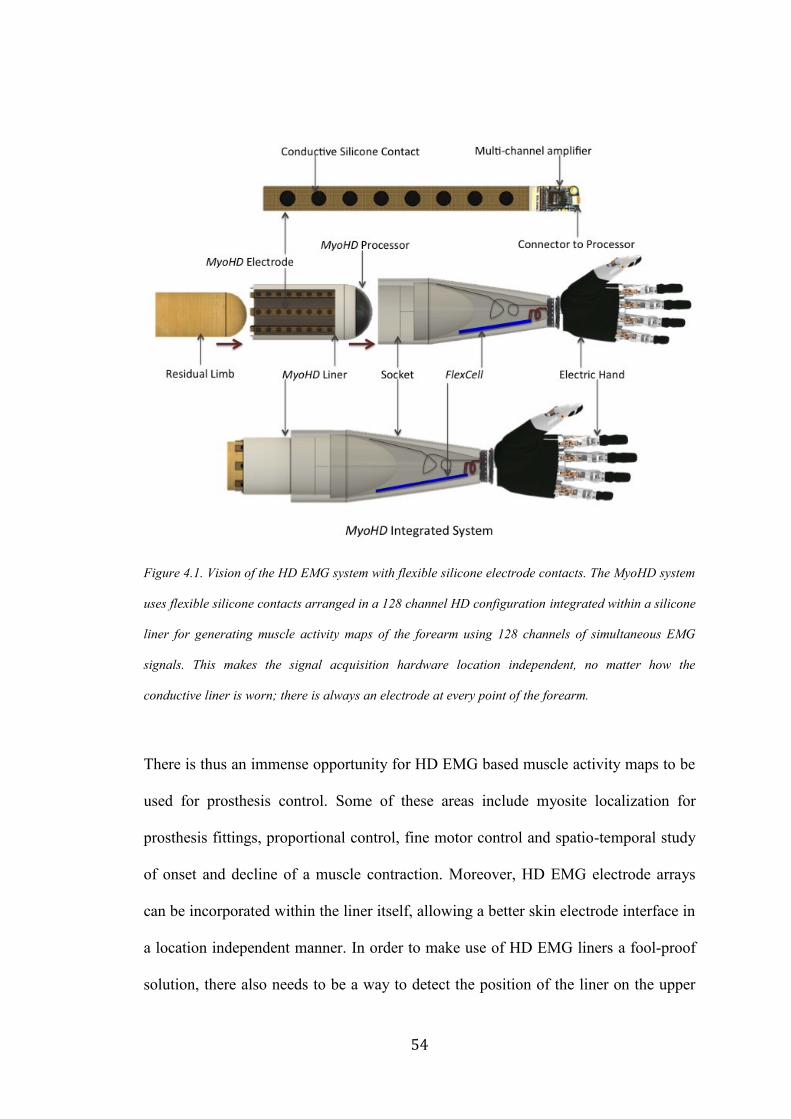
54
Figure 4.1. Vision of the HD EMG system with flexible silicone electrode contacts. The MyoHD system
uses flexible silicone contacts arranged in a 128 channel HD configuration integrated within a silicone
liner for generating muscle activity maps of the forearm using 128 channels of simultaneous EMG
signals. This makes the signal acquisition hardware location independent, no matter how the
conductive liner is worn; there is always an electrode at every point of the forearm.
There is thus an immense opportunity for HD EMG based muscle activity maps to be
used for prosthesis control. Some of these areas include myosite localization for
prosthesis fittings, proportional control, fine motor control and spatio-temporal study
of onset and decline of a muscle contraction. Moreover, HD EMG electrode arrays
can be incorporated within the liner itself, allowing a better skin electrode interface in
a location independent manner. In order to make use of HD EMG liners a fool-proof
solution, there also needs to be a way to detect the position of the liner on the upper
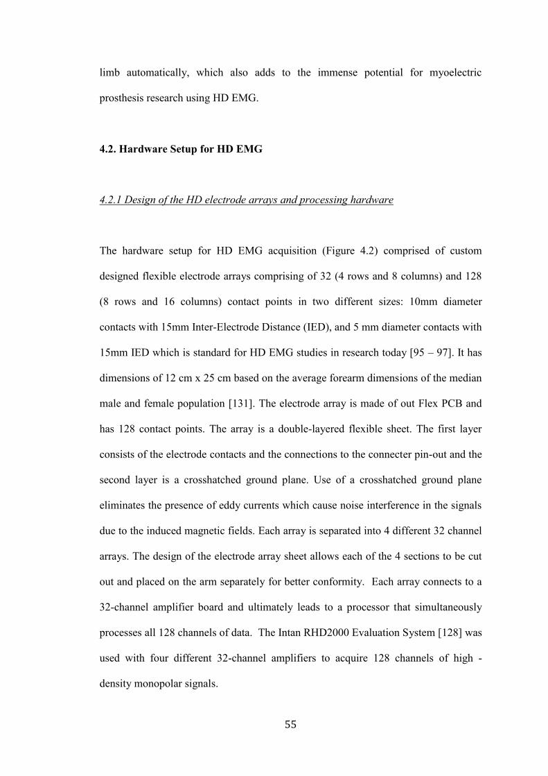
55
limb automatically, which also adds to the immense potential for myoelectric
prosthesis research using HD EMG.
4.2. Hardware Setup for HD EMG
4.2.1 Design of the HD electrode arrays and processing hardware
The hardware setup for HD EMG acquisition (Figure 4.2) comprised of custom
designed flexible electrode arrays comprising of 32 (4 rows and 8 columns) and 128
(8 rows and 16 columns) contact points in two different sizes: 10mm diameter
contacts with 15mm Inter-Electrode Distance (IED), and 5 mm diameter contacts with
15mm IED which is standard for HD EMG studies in research today [95 – 97]. It has
dimensions of 12 cm x 25 cm based on the average forearm dimensions of the median
male and female population [131]. The electrode array is made of out Flex PCB and
has 128 contact points. The array is a double-layered flexible sheet. The first layer
consists of the electrode contacts and the connections to the connecter pin-out and the
second layer is a crosshatched ground plane. Use of a crosshatched ground plane
eliminates the presence of eddy currents which cause noise interference in the signals
due to the induced magnetic fields. Each array is separated into 4 different 32 channel
arrays. The design of the electrode array sheet allows each of the 4 sections to be cut
out and placed on the arm separately for better conformity. Each array connects to a
32-channel amplifier board and ultimately leads to a processor that simultaneously
processes all 128 channels of data. The Intan RHD2000 Evaluation System [128] was
used with four different 32-channel amplifiers to acquire 128 channels of high -
density monopolar signals.
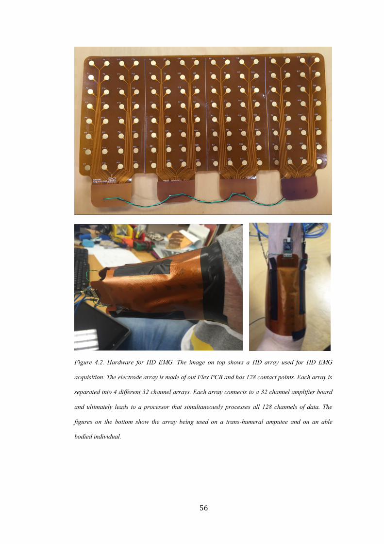
56
Figure 4.2. Hardware for HD EMG. The image on top shows a HD array used for HD EMG
acquisition. The electrode array is made of out Flex PCB and has 128 contact points. Each array is
separated into 4 different 32 channel arrays. Each array connects to a 32 channel amplifier board
and ultimately leads to a processor that simultaneously processes all 128 channels of data. The
figures on the bottom show the array being used on a trans-humeral amputee and on an able
bodied individual.
57
4.2.2. Evaluation of the Electrode Array
4.2.2.1. Experimental Setup
The electrode array was attached to the forearm of an able bodied subject such that it
was 5 centimeters distal from the elbow and wrapped around the forearm completely.
The ground and reference electrodes were connected to the epicondyles on the elbow
for minimizing baseline noise. The subject performed Wrist Flexion, Wrist Extension
and Hand Rest motions and 128 channel data was acquired for the same.
4.2.2.2. Signal Pre-processing
The gathered data were imported into MATLAB The signals were band pass filtered
between 30Hz and 500Hz by a 10th order Butterworth High-pass and Low-pass filter
respectively. An Infinite Impulse Response (IIR) comb filter at 60 Hz was
implemented to remove powerline noise as well as the resonant frequencies associated
with the same. The data were reorganized to resemble the arrangement on the
electrode array and an FFT was performed on each of the 32 or 128 channels of data
(in two separate designs and experiments) to view the frequency spectrum and to
ensure that noise was eliminated.
4.2.2.3. Fast Fourier Transform of the Monopolar Signals
The FFT of the signals from the HD EMG array, before and after filtering. Monopolar
data like that of the HD EMG is very susceptible to motion artefact as well as to the

58
60 Hz powerline noise and its resonant frequencies. The same is evident in the Figure
4.3 below, the peaks in the FFT occur at multiples of 60 Hz. Following the
implementation of an Infinite Impulse Response Comb Filter centered at 60 Hz, as
well as implementation of the low pass and high pass filters as mentioned above, all
noise interference is removed and the signal is used for further processing.
Figure 4.3: Fast Fourier Transform on the Monopolar Signals, before (a) and after (b) filtering.
a
b

59
4.3. HD EMG Muscle Activity Maps
As mentioned in the previous sections, HD EMG has traditionally been used to study
the propagation of localized action potentials by representing the action potentials at
each spot in a two-dimensional spatial image in which the color of each spot indicates
the amount of activity [98 - 99]. The same principle can be applied to HD EMG maps
for myoelectric control. Instead of viewing them as 128 channels of one-dimensional
signal, the signal from each channel can be reduced to a point value reflecting the
activity at the point and plotted as a two-dimensional image of muscle activity of the
forearm. This can be done using time domain based feature extraction methods such
as Root Mean Square (RMS) and Mean Absolute Value (MAV). These images can
now be used for myoelectric control, thus converting a traditionally signal processing
problem into an image processing one.
4.3.1. Creation of Muscle Activity Maps
4.3.1.1. Experimental Setup
The experimental setup was identical to that in Section 4.2.2.1.
4.3.1.2. Signal Preprocessing
The gathered data were imported into MATLAB. The signals were pre-processed
based on the algorithm that has been outlined and verified in Section 4.2.2.2 and
4.2.2.3.

60
4.3.1.3. Creation of Muscle Activation Map
The amplifier channel data from the able-bodied data set were converted to Root
Mean Square (RMS) as well Mean Absolute Values (MAV) following pre-processing.
Both RMS and MAV are two different time domain based feature extraction methods
based on the amplitude of the signal [100].
RMS: Root Mean Square value of a signal x(t) is calculated as the square root of
average of squared value of the signal in a given analysis time window with N
samples. . xk is the kth sample in this analysis window, Mathematically,
RMS = √1
𝑁∑ 𝑥𝑘
2𝑁−1𝑘=0 (Eq. 4.1)
MAV: This feature is the mean absolute value of signal x in an analysis time window
with N samples. xk is the kth sample in this analysis window. This is also called
normalized 1 norm of a signal or vector. Mathematically,
MAV = 1
𝑁 ∑ |𝑥𝑘
𝑁𝑘=1 | (Eq. 4.2)
Studies have shown that the amplitude of the EMG corresponds to the intensity of the
contraction; hence this is a good metric to look at the muscle activity [101]. This data
set was then represented as an 4 x 8 matrix for a 32 channel system and as a 8 x 16
matrix for a 128 channel system respectively, corresponding to the electrode contact
positions on the limb. The matrix was normalized by the maximum RMS or MAV
61
value across all channels. The same process was repeated for the test data set to
generate a 4 x 8 or 8 x 16 matrix with the RMS or MAV values as the pixel at each ijth
position.
The maps obtained using both RMS and MAV measures were almost identical, the
variations occurred in regions intermediate to the maximum and minimum values.
(See Fig 4.4)
Figure 4.4. RMS (a) and MAV (b) Activity Maps. The above images show the activity maps by the
application of two different time domain feature extraction techniques. We can see that both are
almost identical, except for slight variations in areas that are intermediate to the extreme values.
The numbers on the axis represent electrode contact positions.
The numbers on the axis represent electrode contact positions.
The numbers on the axis represent electrode contact positions.
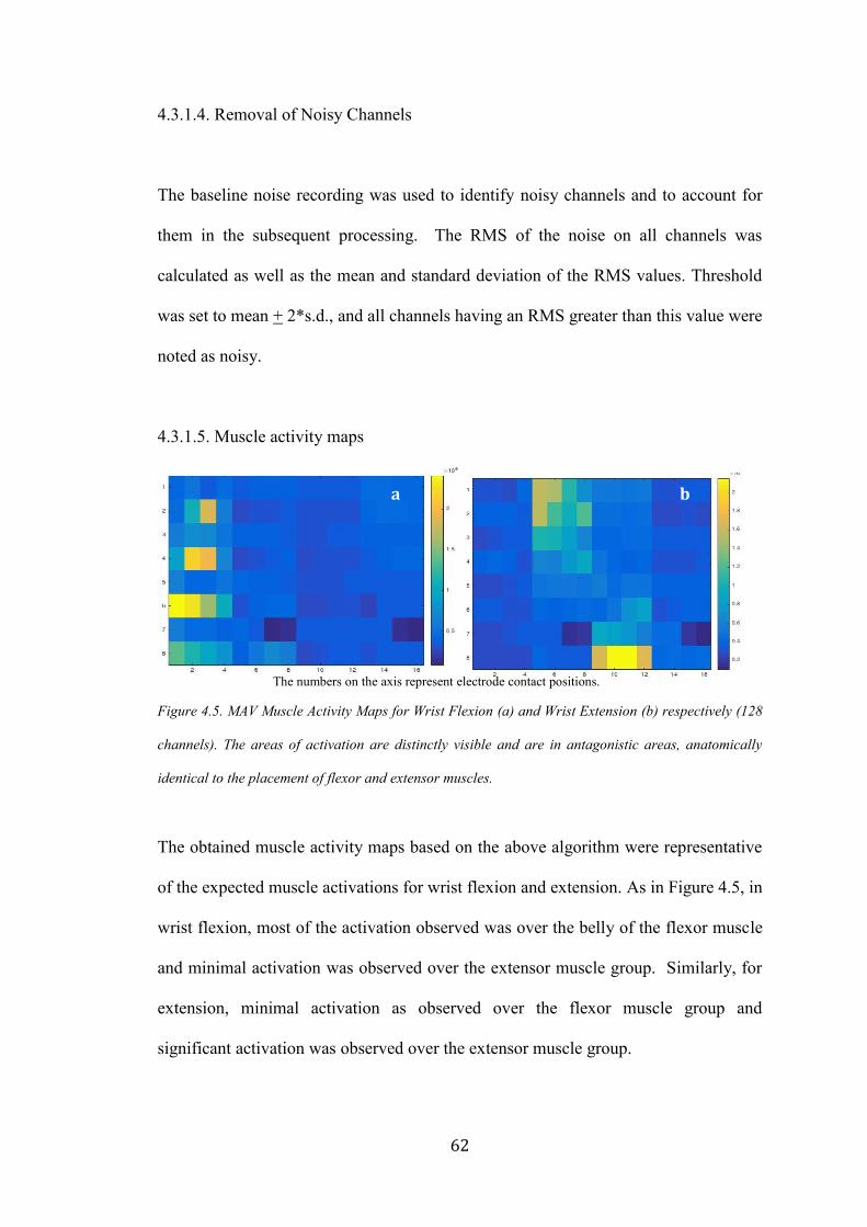
62
4.3.1.4. Removal of Noisy Channels
The baseline noise recording was used to identify noisy channels and to account for
them in the subsequent processing. The RMS of the noise on all channels was
calculated as well as the mean and standard deviation of the RMS values. Threshold
was set to mean + 2*s.d., and all channels having an RMS greater than this value were
noted as noisy.
4.3.1.5. Muscle activity maps
Figure 4.5. MAV Muscle Activity Maps for Wrist Flexion (a) and Wrist Extension (b) respectively (128
channels). The areas of activation are distinctly visible and are in antagonistic areas, anatomically
identical to the placement of flexor and extensor muscles.
The obtained muscle activity maps based on the above algorithm were representative
of the expected muscle activations for wrist flexion and extension. As in Figure 4.5, in
wrist flexion, most of the activation observed was over the belly of the flexor muscle
and minimal activation was observed over the extensor muscle group. Similarly, for
extension, minimal activation as observed over the flexor muscle group and
significant activation was observed over the extensor muscle group.
a b
The numbers on the axis represent electrode contact positions.
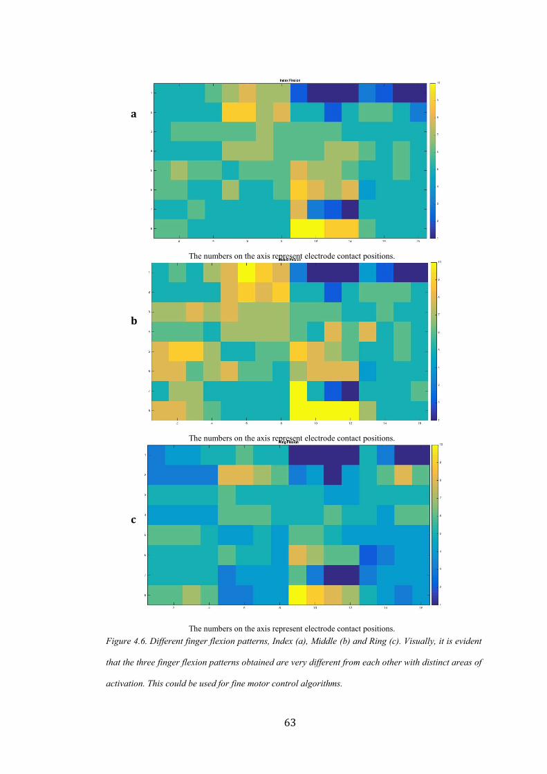
63
Figure 4.6. Different finger flexion patterns, Index (a), Middle (b) and Ring (c). Visually, it is evident
that the three finger flexion patterns obtained are very different from each other with distinct areas of
activation. This could be used for fine motor control algorithms.
a
b
c
The numbers on the axis represent electrode contact positions.
The numbers on the axis represent electrode contact positions.
The numbers on the axis represent electrode contact positions.

64
In addition to the traditional activation areas, additional activation areas could be
identified for both flexion and extension. Activity maps for the respective finger
flexion motions were also distinct from one another and in agreement with existing
literature on the areas of muscle activation [102]. Some of these images are given in
Figure 4.6.
The resolution between the muscle activity maps differed greatly between a 32
channel and 128 channel system as discussed in the next section.
4.3.1.5.1. Methods
An initial proof of concept of the system was implemented with a 32-channel system
and the experiment was repeated again with a 128 channel system. We implemented a
128-channel system to overcome the resolution limitation of a 32-channel system.
Data was gathered from three able bodied subjects and they performed Wrist Flexion,
Wrist Extension and Hand Rest motions. Five trials were performed per movement.
In order to confirm repeatability of the movements, as well as to confirm the
similairty in patterns between two movements, Mean Squared Error (MSE) was used
to determine how closely related the two images were. MSE is a metric of image
quality. It is applicable here since we are trying to quantify if the two images being
studied are idenitical in terms of their data or if they differ then by how much. This is
a normalized frobenius norm of the error matrix. Mathematically,
MSE = 1
𝑀𝑁∑ ∑ [𝑔′(𝑛, 𝑚) − 𝑔(𝑛, 𝑚)]2𝑁
𝑚=1𝑀𝑛=1 (Eq. 4.3)

65
One problem with mean-squared error is that it depends strongly on the image
intensity scaling. A mean-squared error of 100.0 for an 8-bit image (with pixel values
in the range 0-255) looks dreadful; but a MSE of 100.0 for a 10-bit image (pixel
values in [0,1023]) is barely noticeable [133]. However, since all our images are
scaled between 0 – 255, we are unaffected by this problem.
4.3.1.5.2. Results
4.3.1.5.2.1. 32 channel system versus 128 channel system
With a 32-channel resolution, the areas of muscle activation corresponding to wrist
flexion and wrist extension tasks, respectively, are clearly identified (Fig. 4.7).
Certain areas that show high levels of activity correspond to the flexor muscle and the
extensor muscle. The 128-channel system provided greater resolution into the muscle
as can be seen in the images seen in Fig. 4.8.
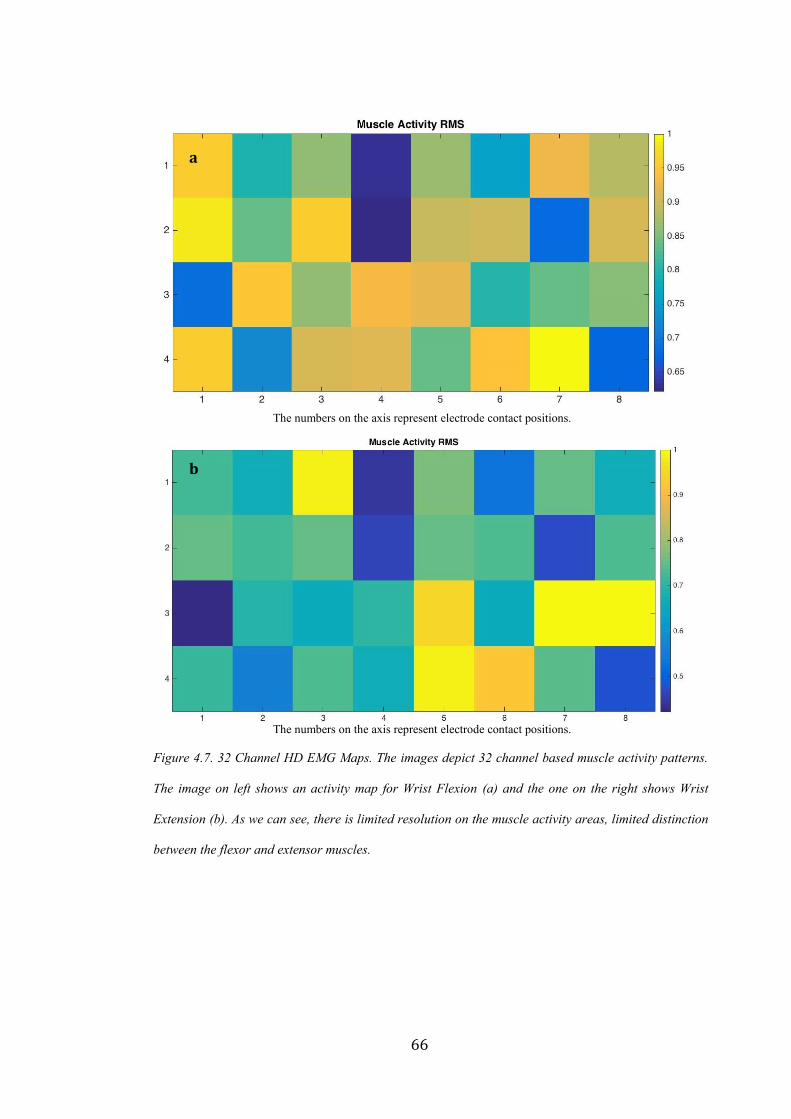
66
Figure 4.7. 32 Channel HD EMG Maps. The images depict 32 channel based muscle activity patterns.
The image on left shows an activity map for Wrist Flexion (a) and the one on the right shows Wrist
Extension (b). As we can see, there is limited resolution on the muscle activity areas, limited distinction
between the flexor and extensor muscles.
a
b
The numbers on the axis represent electrode contact positions.
The numbers on the axis represent electrode contact positions.
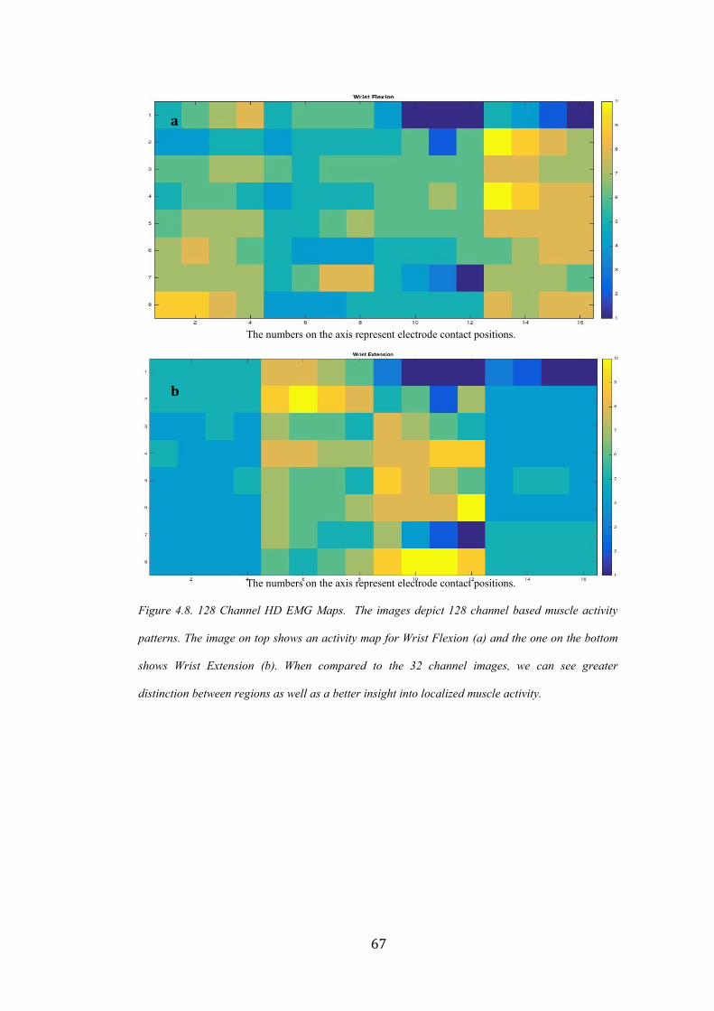
67
Figure 4.8. 128 Channel HD EMG Maps. The images depict 128 channel based muscle activity
patterns. The image on top shows an activity map for Wrist Flexion (a) and the one on the bottom
shows Wrist Extension (b). When compared to the 32 channel images, we can see greater
distinction between regions as well as a better insight into localized muscle activity.
a
b
The numbers on the axis represent electrode contact positions.
The numbers on the axis represent electrode contact positions.

68
4.3.1.5.2.2. Repeatability of Muscle Activity Maps
The data from one subject is presented below in Table 4.1. The datasets A, B, C, D, E
represent five different Wrist Flexion data sets acquired from a single subject with the
electrode arrays placed on the forearm in the same position every single time.
Table 4.1. Mean Squared Error between 5 Wrist Flexion Muscle Activity Maps
Type of Motion Trial Number Dataset Combination Mean Squared Error
Hand Flexion 1 A, B 0.0771
2 A, C 0.1651
3 A, D 0.1167
4 A, E 0.0144
5 B, C 0.065
6 B, D 0.0441
7 B, E 0.0499
8 C, D 0.0066
9 C, E 0.1515
10 D, E 0.103
AVERAGE 0.07934
The very low MSE indicates that the images are very minimally different from each
other, in other words, they are repeatable. Thus the data acquisition hardware, as well
as the algorithmic processing is working reliably and the muscle activity maps
generated are usable for further studies.
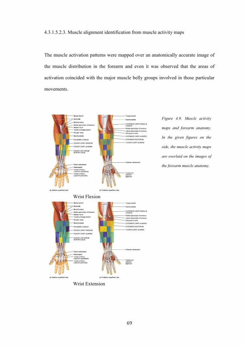
69
4.3.1.5.2.3. Muscle alignment identification from muscle activity maps
The muscle activation patterns were mapped over an anatomically accurate image of
the muscle distribution in the forearm and even it was observed that the areas of
activation coincided with the major muscle belly groups involved in those particular
movements.
Wrist Flexion
Wrist Extension
Figure 4.9. Muscle activity
maps and forearm anatomy.
In the given figures on the
side, the muscle activity maps
are overlaid on the images of
the forearm muscle anatomy.

70
4.3.1.5.3. Discussion
4.3.1.5.3.1. 32-channel versus 128-channel system
The 32-channel system has several drawbacks. Lack of adequate resolution is evident.
Even though the system provides very global EMG information, it is difficult to
extract local, muscle-specific EMG information. In addition, the number of channels
are not sufficient to generate distinction between different muscle activity patterns
corresponding to different tasks or movements that use similar muscle anatomy. In
order to get more detailed insight into the muscle activity patterns, scaling up to a 128
channels becomes essential.
With a 128-channel system, there was greater distinction between different muscle
activation patterns to the extent that the signals can be used for proportional control as
well as for fine motor control of the artificial electric hand as will be demonstrated in
the next few sections.
4.3.1.5.3.2. Repeatability of Muscle Activity Maps
The average MSE for 10 different combinations of 5 datasets for hand flexion from a
single subject is 0.07934. This low value indicates that the data acquired is repeatable
in nature and hence can be used for further processing and analysis.

71
4.3.1.5.3.3. Muscle alignment identification from muscle activity maps
The muscle activity maps from both flexion and extension correlate well with the
areas where the flexor and extensor muscle are on the forearm. It is possible that with
additional research, we can use muscle activity maps to determine secondary muscle
groups that are also used for a given hand motion.
4.4. Use of HD EMG in Myoelectric Prosthesis
4.4.1. Finger Identification and HD EMG Signal Acquisition for Proportional Control
4.4.1.1. Introduction
As seen from the previous sections, HD EMG maps give greater insight into muscle
activation patterns for different hand motions. Moreover, it is possible to identify
specific channels that provide the most distinct information for pattern recognition
based control (Appendix, Section 6.1.1). These significant distinctions could
potentially be used for discerning individual finger motions or a combination of finger
motions. Moreover, the ability to study the temporal variation of a contraction may
also allow for proportional control of the prosthesis.
4.4.1.2. Methods
As a proof of concept of this theory, we constructed HD EMG maps and ran them
through a KL divergence algorithm (Appendix, Section 6.2) to determine if we could
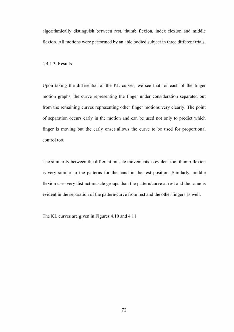
72
algorithmically distinguish between rest, thumb flexion, index flexion and middle
flexion. All motions were performed by an able bodied subject in three different trials.
4.4.1.3. Results
Upon taking the differential of the KL curves, we see that for each of the finger
motion graphs, the curve representing the finger under consideration separated out
from the remaining curves representing other finger motions very clearly. The point
of separation occurs early in the motion and can be used not only to predict which
finger is moving but the early onset allows the curve to be used for proportional
control too.
The similarity between the different muscle movements is evident too, thumb flexion
is very similar to the patterns for the hand in the rest position. Similarly, middle
flexion uses very distinct muscle groups than the pattern/curve at rest and the same is
evident in the separation of the pattern/curve from rest and the other fingers as well.
The KL curves are given in Figures 4.10 and 4.11.

73
Figure 4.10. KL curves for hand at rest and for thumb flexion. In the above figures, we see that
the KL curves separate out very neatly during thumb flexion. By looking at the differential of
the divergence, we are able to determine the actual onset of the movement.
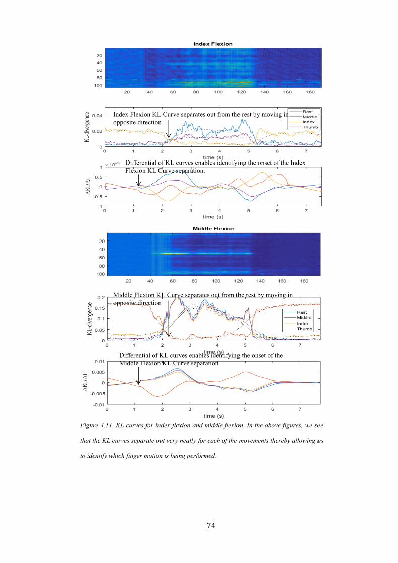
74
Figure 4.11. KL curves for index flexion and middle flexion. In the above figures, we see
that the KL curves separate out very neatly for each of the movements thereby allowing us
to identify which finger motion is being performed.
Index Flexion KL Curve separates out from the rest by moving in
opposite direction
Differential of KL curves enables identifying the onset of the Index
Flexion KL Curve separation.
Middle Flexion KL Curve separates out from the rest by moving in
opposite direction
Differential of KL curves enables identifying the onset of the
Middle Flexion KL Curve separation.

75
4.4.1.4. Discussion
Based on the data gathered and the K-L Divergence graphs given in Figure 4.10 and
4.11 not only are we able to determine which finger is being moved, we are also able
to identify its onset early into the contraction. With greater research and evaluation on
a larger dataset, the preliminary results in this section could be validated to become
one of the first approaches in finger decoding and proportional control of prosthesis
using HD EMG.
4.4.2. Time Varying Mapping of a Muscle Contraction from Onset to Decline
4.4.2.1. Introduction
The study of muscle activity is interesting and allows us to understand the nature of
propagation of EMG signals from the surface of upper and lower limbs. This is
important for multiple reasons. The direction of propagation of muscle signals helps
in better alignment of EMG electrodes in a prosthesis. This is particularly important
for amputees since post amputation, their muscle alignment and muscle activity can
differ significantly from traditional anatomy. Study of muscle contractions can also
facilitate better and more natural control of prosthesis by controlling an electric hand
proportionally to the stage of the contraction itself.

76
4.4.2.2. Methods
We recorded 128-channel muscle activity from the entire forearm of an able bodied
subject for a hand flexion from the beginning of the contraction to the end. The 128-
channel signals acquired over a 10 second interval were windowed into 250
millisecond time intervals. Each windowed signal channel was converted into a
muscle activity map by the protocol mentioned in section 4.3.1.3.
4.4.2.3. Results
Figures 4.12 – 4.14 show the images of the contraction evolving over time i.e. onset,
maximum contraction and decline. We observe that when the muscle is at the
maximum contraction, the activity maps alternate with high and low bursts of activity.

77
Figure 4.12. Onset of Contraction. The above maps show the onset of contraction in a flexor
muscle during hand flexion. The onset of a contraction is fairly gradual, with muscle activity
increasing over the bulk of the muscle over time. The cue was presented at 1 second.
0 s 0.5 s
1 s 1.5 s
2 s 2.5 s
3 s 3.5 s
Presentation of cue
Area corresponding
to flexor muscle
beginning to show
activity.
Significant muscle
activity in flexor
muscle area
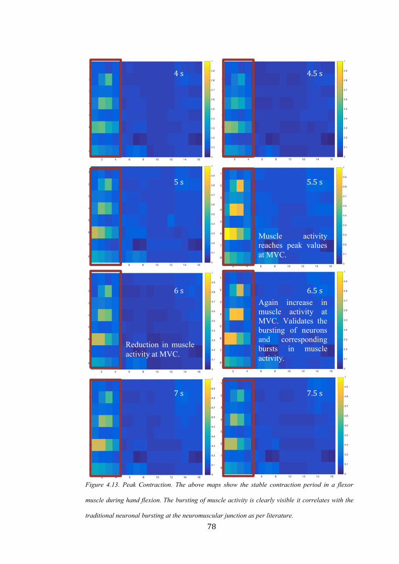
78
Figure 4.13. Peak Contraction. The above maps show the stable contraction period in a flexor
muscle during hand flexion. The bursting of muscle activity is clearly visible it correlates with the
traditional neuronal bursting at the neuromuscular junction as per literature.
4 s 4.5 s
5 s 5.5 s
6 s 6.5 s
7 s 7.5 s
Muscle activity
reaches peak values
at MVC.
Reduction in muscle
activity at MVC.
Again increase in
muscle activity at
MVC. Validates the
bursting of neurons
and corresponding
bursts in muscle
activity.

79
Figure 4.14. Decline of Contraction. The above maps show the decline of contraction in a flexor
muscle during hand flexion. The decline is pretty quick; muscle activity reduces to almost
negligible within a few seconds.
8 s 8.5 s
9 s 9.5 s
10 s 9.5 s
Instantaneous
decline in muscle
activity at the end of
the contraction.
80
4.4.2.4. Discussion
The spatio-temporal maps also correspond to specific time frames in the contraction
and give us an interesting insight into multiple aspects:
a. The order of muscle activation for a given contraction
b. The ability to predict which stage the contraction is in
c. Using the above two, we should now be able to implement finer motor signal
decoding and, subsequently, proportional control of the hand by algorithmically
determining which fingers to move and by how much.
Moreover, we speculate that the bursting observed at maximum contraction may
correlate with neuronal bursting at the neuromuscular junction and subsequent EMG
bursting as reported in the literature [106].
The HD EMG signal acquisition and signal (and reconstructed image) processing
approach should allow us to use image-processing techniques. Further, conducting
time varying study of the muscle contraction activity maps should allow for video-
graphical processing techniques as well for more developed myoelectric signal
decoding, pattern recognition, and eventually control.
81
4.4.3. Automatic Liner Position Detection
4.4.3.1. Introduction
Preliminary studies reported in the previous sections establish future use of HD EMG
as a more reliable, robust, location independent method for myoelectric signal
acquisition and decoding. Such decoding should prove to be beneficial for achieving a
more precise prosthesis control. However, for integrating HD EMG into a liner
system that is usable for an amputee, a very important next step would be to
determine the orientation of the electrode contacts, and thus by extension of the liner
on an amputee’s limb without regular re-calibration or training. The ability to do the
same algorithmically can ensure that a liner based HD EMG system will make
prosthesis control a very intuitive process for the amputee. The next section presents
one way to algorithmically determine the position of the liner on a residual limb.
4.4.3.2. Methods
We collected an initial calibration dataset from an able bodied subject with the
electrode array attached to the limb and positioned such that the electrode contact
coincided with the belly of the flexor muscle and the proximal end of the HD array
was 2 inches from the elbow. We recorded baseline noise signal of 5 seconds,
followed by 5 seconds of the user performing Maximum Volume Contraction (MVC)
for a specific hand motion such as Wrist Flexion.
We also gathered a test data set from the same subject by wearing the electrode array
in a random position on the limb. We collected the same signals as highlighted above
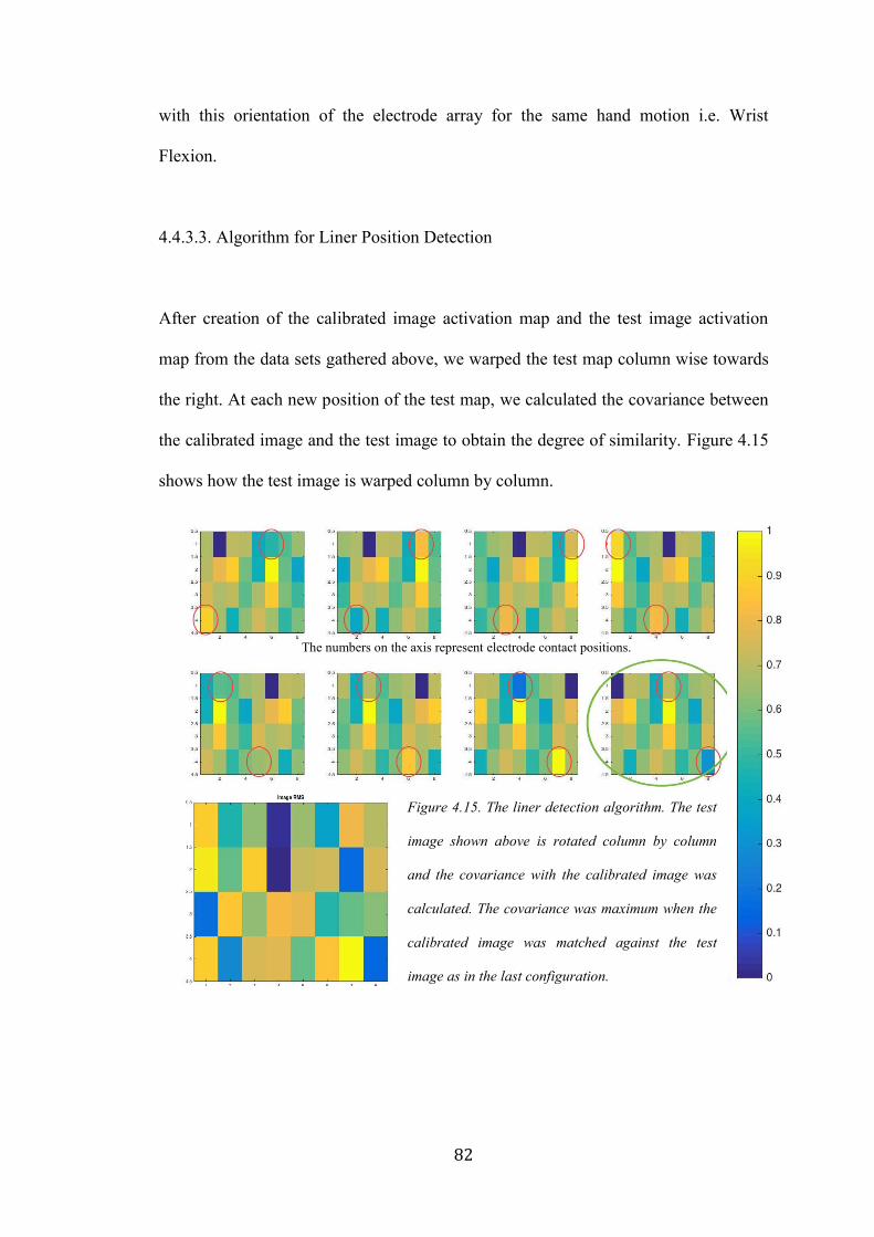
82
with this orientation of the electrode array for the same hand motion i.e. Wrist
Flexion.
4.4.3.3. Algorithm for Liner Position Detection
After creation of the calibrated image activation map and the test image activation
map from the data sets gathered above, we warped the test map column wise towards
the right. At each new position of the test map, we calculated the covariance between
the calibrated image and the test image to obtain the degree of similarity. Figure 4.15
shows how the test image is warped column by column.
Figure 4.15. The liner detection algorithm. The test
image shown above is rotated column by column
and the covariance with the calibrated image was
calculated. The covariance was maximum when the
calibrated image was matched against the test
image as in the last configuration.
The numbers on the axis represent electrode contact positions.

83
In order to account for the noisy channels, we replaced every noisy channel pixel with
the corresponding pixel value from the calibrated image. The noisy channels were
replaced with a new data set with every warp to ensure that the data in the noisy
channel pixel matched the data in the calibrated image pixel that it would be
compared with. The pixels encircled in red in Figure 4.15 represent the noisy channels
that are replaced with the values from the calibrated image.
4.4.3.4. Results
The green encircled image represents the position of the test image that gave the
highest covariance with the calibrated image, thus identifying the position of the
electrode array with respect to the limb. The channels were re-numbered to match this
configuration for further signal acquisition and processing and prosthetic control.
4.4.4. Electrode Site Location for Prosthesis Fitting
4.4.4.1. Introduction
Apart from use for prosthesis control, HD EMG has other very useful functions in the
prosthesis realm especially in prosthesis fittings. Myosite location (Locations on the
residual limb that provide high quality EMG signals) is one of the most important
steps in the process of myoelectric prosthesis fitting. This is because identification of
the best locations for electrode placement governs the quality of EMG signals and the
subsequent performance of control algorithms [107 - 108]. The process requires
precision, even for two-site based direct control systems that use antagonistic muscle

84
groups. The current industry standard is to manually palpate the residual limb while
the patient performs a contraction to identify broad areas of muscle movement and
then to use a differential electrode system for finer identification of myosites [109 -
110]. Shifting an electrode even by <1 cm over the muscle causes significant changes
in sEMG amplitude subsequently affecting the quality of control [28, 111 - 112]. The
time required as well as the reliability of this process is solely dependent on the
skillset of the prosthetist, thus making it a highly specialized procedure.
New control strategies such as pattern recognition [113 - 117] use up to eight EMG
sites for signal acquisition. In the case of above elbow amputation patients especially,
all eight of these electrodes need to be placed in specific locations on the residual
limb to maximize information content of each channel. With emerging control
strategies such as pattern recognition which require multiple electrode sites, the
problem of myosite identification is likely to become increasingly more challenging
over traditional two-site direct control systems. Thus, there is a significant need to
improve upon the traditional manual or empirical method of myosite location.
We have developed a novel flexible High-Density EMG array to “image” a patient’s
residual limb prior to socket fabrication. This system generates muscle activity maps
from 128 channels of simultaneously recorded monopolar EMG signals. The muscle
activity maps provide a visual means of identifying all potential myosite locations for
a given contraction. Moreover, by analyzing different muscle activity maps for
different hand motions and contractions, it should be possible to determine the most
unique combination of sites that provide differentiable patterns for control.
85
4.4.4.2 Methods
The HD EMG array was attached so as to cover the entire residual limb of a
transhumeral amputee patient. The patient was asked to perform the eight different
hand motions that were repeatable for him namely: Wrist Extension, Wrist Flexion,
Hand Open, Hand Close, Pinky Flexion, Thumb Flexion, Pronation and Supination.
128 channels of monopolar signals were acquired and converted to muscle activity
maps as per the algorithm highlighted in Section 4.3.1.3.
4.4.4.3. Results
Given below in Figure 4.16, are the images depicting six distinct motions that a
transhumeral amputee performed. The muscle activity maps for each of the six
motions were analyzed to determine a combination of eight locations that was distinct
to each motion. A differential electrode was used at the eight spots identified from the
HD EMG maps to determine their orientation for attachment within the prosthesis for
optimum signals.

86
4.4.4.4. Discussion
Use of this HD-EMG interface allowed for optimized identification of eight myosites
for pattern recognition-based prosthesis fitting of a patient with a transhumeral
amputation. Interestingly, in this case study, we identified unique EMG sites where
there was little visually identifiable movement of the residual limb. Such sites would
likely be missed by traditional myosite selection methods. Moreover, the time taken
to identify all eight spots was fractional of the time taken when the myosites are
located using traditional methods. Using the selected sites, the patient was
subsequently successfully fit with a pattern recognition prosthesis. Thus, HD EMG is
a valuable myosite visualization and identification tool that augments the prosthetists’
skillset in myosite location.
Figure 4.16. HD EMG maps for Myosite Location. Six distinct motions performed by an amputee
subject to determine unique myosite locations for pattern recognition based control. The muscle
activity maps for amputees will be highly variable based on the muscle arrangement following
surgery and amputee. Muscle activity maps will be unique to each amputee.
c
87
4.5. Summary
This research paves the way for incorporating flexible electronics within a prosthetic
liner. First, we developed thin flexible HD EMG array, and next we laid out the
foundation of algorithms for image based EMG signal decoding for prosthetic control.
This has advantages due to multiple reasons:
1. A silicone liner fits the residual limb with better compression and doesn’t move
relative to the residual limb, allowing for better stability for the electrode skin
interface.
2. It separates the electronics from the socket, which prevents problems like
electrode lift off and electrode migration.
3. Use of HD EMG eliminates the need for location specificity of the electronics
and makes prosthesis fittings a more generic process.
4. Eliminating location specificity and embedded electronics in a liner allows for
use of a silicone liner with a myoelectric prosthesis. This enables fabrication of a
socket with greater compression without significant damage to the residual limb.
5. It paves way for a new generation of robust, stable, more intuitive image
controlled myoelectric prosthesis.

88
CHAPTER 5
5. Conclusion and Future Directions
Use of flexible electronics in conjunction with HD EMG is a novel approach that is
yet to be explored for reliable myoelectric prosthesis control. We have established a
number of relationships and parameters.
* The Skin Electrode Complex Impedance and SNR relationship
* Flexible electronics and HD EMG to be integrated with myoelectric prosthesis
systems in numerous different ways.
* Demonstration of fine motor control, proportional control, temporal study of a
contraction as well as myosite localization using HD EMG
This chapter provides the summary and discussion.
5.1. Flexible Contacts
5.1.1. Flexible Electrodes in Socket for Myoelectric Prosthesis
On account of development of numerous different flexible conductive materials as
well as due to a uniform method of characterizing them, there is an opportunity for
redesign of current rigid electrodes that are embedded in a socket. By use of the
flexible electrodes in a remote configuration such that the amplification is performed
at a remote location, the size as well as the rigidity of traditional socket electronics
can be eliminated.

89
Similarly, additional research in the realm of silicone encased flex PCB electrodes can
now be pursued more easily with development of conductive silicones that conduct
EMG signals with high SNR. Using SECI, the materials can be characterized more
uniformly and the electrodes developed out of doped traditionally non-conductive
materials will have stable and repeatable electrical characteristics.
5.1.2. Flexible Electrodes in Liner for Myoelectric Prosthesis
Replacement of rigid electronics in the socket with flexible contacts and electrodes is
one important aspect of future EMG acquisition for prosthesis control. In addition, the
more comprehensive solution is to incorporate the electrodes within the liner itself.
Moreover, a key aspect of improved electronics for myoelectric signal acquisition for
prosthesis control would include elimination of wired electronic components.
Development of encasing techniques and wireless data and power transfer methods
would facilitate incorporation of wireless electronics within the liner itself and would
eliminate the dependency on wired connections and the constraints due to them.
Moreover, use of other flexible materials such as silk, elastic, PDMS and techniques
such as screen-printing with conductive ink and traces can revolutionize wearable
electronics for EMG acquisition and control of myoelectric prosthesis.
Flexible electrode contacts are the first step towards making prosthesis electronics
completely flexible. Next generation thin film electronics and wireless data and power
transmission technologies will augment the translation towards completely conformal
electronics for the most stable and robust prosthesis control.
90
5.2. High Density EMG
5.2.1. HD EMG for Fine Motor Decoding and Signal Acquisition for Proportional
Control
Based on the preliminary results generated in the previous chapter, it is evident that
HD EMG muscle activity maps have the potential to be used for both individual
finger control and proportional control for myoelectric prosthesis. With algorithms
already in place to mitigate problems created by electrode shift, image based
prosthesis control could become a reality and a more efficient means of control. Not
only will users regain dexterity, it has a future potential for allowing multiple degrees
of freedom using simple EMG signals.
Fine motor control and proportional control continue to remain a research problem,
which requires a more optimized solution that can be implemented on fairly
constrained processors for integration with actual myoelectric prosthesis. Channel
optimization, image based processing and pattern recognition together can help in
creating more intuitive prosthesis control systems.
5.2.2. HD EMG for Myoelectric Prosthesis Fitting
In the singular pattern recognition prosthesis fitting case study mentioned in the
previous chapter, it is evident that HD EMG could become a very valuable tool in
multi-site, prosthesis fitting. While the current implementation is by means of an
offline system, a real-time system along with a visualization GUI tool would allow
91
the prosthetist to understand and correlate the array placement on the forearm with the
muscle activity maps on the screen can make prosthesis fitting sessions more accurate
and less time consuming. Moreover, the setup will allow for identification of the
electrically best spots for signal acquisition, not only the ones that visibly move
during a contraction.
In a further advanced implementation of the system, we could algorithmically
determine the best combination of sites for electrode placement without any
intervention from the prosthetist himself.
5.2.3. HD EMG in Socket for Myoelectric Prosthesis
While flexible electronics within the socket will significantly improve the stability of
the skin electrode interface, use of HD EMG in a modular architecture will allow for
greater robustness of the system by combining the benefits of a flexible remote
system in a high-density configuration. Not only will this prevent electrode lift off
and migration, it will eliminate the need for electrodes to be fabricated into the exact
positions within a socket. Instead multiple arrays of remote monopolar electrodes
could be attached to form a HD EMG configuration and provide a more advanced
interface to myoelectric control.
This will lead to a significant shift in the current electronics design for upper limb
prosthesis. Use of HD EMG will require a shift from traditional differential control to
monopolar signal based control, for better noise removal as well as will allow the
implementation of a very modular and modifiable system.
92
The control strategy will no longer be dependent on the electronics used for the signal
acquisition and the user will have the ability to choose between different control
strategies using the same electrode interface without having to undergo a completely
new fabrication of their socket and prosthesis.
5.2.4. HD EMG in Liner for Myoelectric Prosthesis
Incorporation of HD EMG within a socket is one way of improving the current
electrode interface to make it more universally compatible with different control
schemes. However, in order to create a fool proof solution for prosthetic control, it is
essential that the skin electrode interface be a very stable one. For this, the electronics
would have to be independent of the socket so that socket movement does not
interfere with the signal acquisition.
Thus, the most optimum solution for the hardware for signal acquisition would be to
integrate the electronics within the silicone prosthetic liner itself, using the flexible
silicone contacts as well as the HD EMG flex PCB array.
Moreover, further research would enable printing of the HD EMG array on materials
such as textiles like silk as well as into thin film tattoos on the skin itself which is
capable of wirelessly interfacing with the remaining processing electronics.
From an even futuristic point of view, these electronics could be implanted into the
residual limb itself thus ensuring that they are always acquiring the best EMG signal
93
from the best spots and are no longer affected by changes in their external
environment.
In the realm of electronics development for myoelectric control, we have made great
strides in implementing innovative technologies to improve signal acquisition and
processing. However, we have a long way to go before we can use electronics and
algorithms to realistically replace a lost limb and truly achieve our goal of restoring
complete limb control to an amputee.
94
6. Appendix
6.1. Ongoing Collaborative Research using the HD EMG developed as a part of this
thesis
6. 1.1. Channel Subset Selection
HD EMG maps, open a new dimension of image based pattern recognition control of
a myoelectric arm. The value of a signal source can be quantified based on its
contribution to the recognition task at hand. When multiple signal sources are
available, as is the case when decoding movement intentions from multichannel
EMG, each of the channels can be ranked based on their respective contributions in
terms of discrimination relevance [103]. By promoting channels of maximum
relevance while reducing the influence of irrelevant or redundant channels, a much
smaller channel subset emerges which is often equivalent or superior at performing
the pattern recognition task [104 - 105]. Our HD EMG platform allows us to localize
myoelectric channel sources which supply the most relevant task information for an
individual human user. Due to this, the electrode location in the prosthesis no longer
has to be customized for every individual. Instead, we can algorithmically determine
the best subset of channels from 128 channels for signal acquisition for subsequent
prosthesis control. Moreoever, the ability to choose channels on the fly provides
greater flexibility in choice of control strategy since the prosthesis hardware no longer
has to be customized for it. Adding higher number of channels in the HD EMG
format also has the potential to provide additional diagnostic insight into a person’s

95
specific post-trauma innervated muscle anatomy and their potential ability to use
myoelectrically controlled devices.
6.1.1.2. Methods
For an initial proof of concept,
data from one able bodied
subject was used. The subject
was asked to perform different
hand motions such as Wrist
Flexion, Wrist Extension,
Pronation, Supination, Hand
Open and Hand Close. After
using the HD EMG array to
collect data, user-specific
movement patterns can be
established (Fig. 4.4).
6.1.1.3. Results
Physical observation of these patterns demonstrates that not all of the 128 channels
are activated which, in itself, can tell us a great deal about the user’s muscular
anatomy. However, we can quantify the relative contribution of each channel to these
movement patterns using separability criteria such as Bhattacharyya distance and
mutual information [103-105] to make precise determinations about its degree of
Figure 6.1. EMG pattern recognition performance based
on feature relevancy. A reduced subject-specific optimal
channel subset can be identified for movement decoding
that is smaller than the baseline full channel set, and this
subset may perform significantly better. Additionally,
irrelevant and noise channels can be identified and
removed with no penalty on performance.
96
influence. We rank the influence of all channels 3-ways: (i) identify irrelevant
channels [105] which provide little to no information other than perhaps noise, (ii)
identify maximally relevant channels critical to the pattern recognition objective, and
(iii) identify partially relevant channels which are supplementary or redundant to
varying degrees. We then choose to include or exclude certain of these channels based
on their relative contributions.
6.1.1.4. Discussion
Determining such an optimal subset of signal channels is desirable in EMG pattern
recognition for a number of reasons. First, limiting the amount of information to be
actively processed improves he speed of real-time computation and processing.
Second, it can be shown (Fig. 4.6.) that such a subset may improve the overall pattern
recognition performance. From this 40 channel subset of the original 128 channels,
the decoding accuracy is the highest when using only the twelve most informative
channels. The improvement gained from the reduced channel set indicates that, not
only are certain channels irrelevant to the pattern recognition task, but that some of
them can actually be misleading. The influence of specific channels will vary from
user to user, but identifying and discarding irrelevant or misleading channels for that
user should make decoding their intended movements more robust.
97
6.2. K L Divergence Algorithm Theory [132]
To measure the difference between two probability distributions over the same
variable x, a measure, called the Kullback-Leibler divergence, or simply, the KL
divergence, has been popularly used in the data mining literature. The concept was
originated in probability theory and information theory.
The KL divergence, which is closely related to relative entropy, information
divergence, and information for discrimination, is a non-symmetric mea- sure of the
difference between two probability distributions p(x) and q(x). Specifically, the
Kullback-Leibler (KL) divergence of q(x) from p(x), denoted DKL(p(x),q(x)), is a
measure of the information lost when q(x) is used to approximate p(x).
Let p(x) and q(x) are two probability distributions of a discrete random variable x.
That is, both p(x) and q(x) sum up to 1, and p(x) > 0 and q(x) > 0 for any x in X.
DKL(p(x),q(x)) is defined in Equation (6.1).
DKL(p(x)||q(x)) = ∑ 𝑝(𝑥𝑥∈𝑋 ) ln𝑝(𝑥)
𝑞(𝑥) (Eq. 6.1)
The KL divergence measures the expected number of extra bits required to code
samples from p(x) when using a code based on q(x), rather than using a code based on
p(x). Typically p(x) represents the “true” distribution of data, observations, or a
precisely calculated theoretical distribution. The measure q(x) typically represents a
theory, model, description, or approximation of p(x).
Although the KL divergence measures the “distance” between two distributions, it is
not a distance measure. This is because that the KL divergence is not a metric
98
measure. It is not symmetric: the KL from p(x) to q(x) is generally not the same as the
KL from q(x) to p(x). Furthermore, it need not satisfy triangular inequality.
Nevertheless, DKL(P||Q) is a non-negative measure. DKL(P||Q) ≥ 0 and DKL(P||Q) = 0
if and only if P = Q.
Notice that attention should be paid when computing the KL divergence. We know
limp→0 p log p = 0. However, when p = 0 but q = 0, DKL(p||q) is defined as ∞. This
means that if one event e is possible (i.e., p(e) > 0), and the other predicts it is
absolutely impossible (i.e., q(e) = 0), then the two distributions are absolutely
different. However, in practice, two distributions P and Q are derived from
observations and sample counting, that is, from frequency distributions. It is
unreasonable to predict in the derived probability distribution that an event is
completely impossible since we must take into account the possibility of unseen
events.
99
REFERENCES
[1] S. Sudarsan, E. Chandra Sekaran, “Design and Development of EMG Controlled
Prosthetics Limb”, Procedia Engineering, Volume 38, 2012, Pages 3547-3551,
[2] G Purushothaman. “Myoelectric Control of Prosthetic Hands: State-of-the-Art
Review.” Medical Devices (Auckland, N.Z.), 2016: 247–255. PMC.
[3] Carey SL, Lura DJ, Highsmith MJ; CP.; FAAOP. “Differences in myoelectric and
body-powered upper-limb prostheses: Systematic literature review”. J Rehabil Res
Dev. 2015 ;52(3):247-62.
[4] A Searle and L Kirkup, “A direct comparison of wet, dry and insulating
bioelectric recording electrodes”, Physiological Measurement, 2000, Volume 21,
Issue 2, pp. 271
[5] Link: http://jjengineering.info/EMG_AMPLITUDE.html
[6] Padmadinata F Z, Veerhoek J J, Van Dijk G J A and Huijsing J H, 1990,
Microelectronic skin electrode Sensors Actuators, 491–4
[7] Taheri B, Knight R and Smith R, “A dry electrode for EEG recording”
Electroencephalogry. Clin. Neurophysiol. 1994, Volume 90, pp. 376–83
[8] Liberating Technologies Inc.
100
[9] Smith, Lauren H., and Levi J. Hargrove. “Comparison of Surface and
Intramuscular EMG Pattern Recognition for Simultaneous Wrist/hand Motion
Classification.” Conference proceedings : Annual International Conference of the
IEEE Engineering in Medicine and Biology Society. IEEE Engineering in Medicine
and Biology Society Conference, 2013, 4223–4226. PMC.
[10] Jayme S. Knutson, Gregory G. Naples, P. Hunter Peckham, Michael W. Keith,
“Electrode fracture rates and occurrences of infection and granuloma associated with
percutaneous intramuscular electrodes in upper-limb functional electrical stimulation
applications”, Journal of Rehabilitation, Research and Development, 2002, Vol. 39
No. 6, Pages 671-684
[11] Ningqi Luo; Jun Ding; Ni Zhao; Leung, B.H.K.; Poon, C.C.Y., "Mobile Health:
Design of Flexible and Stretchable Electrophysiological Sensors for Wearable
Healthcare Systems," in Wearable and Implantable Body Sensor Networks (BSN),
2014, vol., no., pp.87-91
[12] Bergey G E, Squires R D and Sipple W C, “Electrocardiogram recording with
pasteless electrodes”. IEEE Trans. Biomed. Eng. 1971, Volume 18, pp. 206–11
[13] C. Pylatiuk, M. Müller-Riederer, A. Kargov, S. Schulz, O. Schill, M. Reischl and
G. Bretthauer, “Comparison of Surface EMG Monitoring Electrodes for Long-term
Use in Rehabilitation Device Control”, IEEE 11th International Conference on
Rehabilitation Robotics Proc., 2009, June 23-26

101
[14] Masayuki Ohyama, Yutaka Tomita, Satoshi Honda, Hitoshi Uchida, Noriyoshi
Matsuo, “Active Wireless Electrodes for Surface Electromyography”, 18th Annual
International Conference of the IEEE Engineering in Medicine and Biology Society,
1996, 1.7.2: Telemetry I1
[15] Experimental Study of an EMG-Controlled 5-DOF Anthropomorphic Prosthetic
Hand for Motion Restoration, Journal of Intelligent and Robotic Systems, Article, Jun
2014
[16] L. Hargrove, K. Englehart and B. Hudgins, "The effect of electrode
displacements on pattern recognition based myoelectric control," 2006 International
Conference of the IEEE Engineering in Medicine and Biology Society, New York,
NY, 2006, pp. 2203-2206.
[17] Yu Mike Chi, Tzyy-Ping Jung and Gert Cauwenberghs, “Dry-Contact and
Noncontact Biopotential Electrodes: Methodological Review”, 2010, IEEE Reviews
In Biomedical Engineering, Vol. 3
[18] Vidovic MM, Paredes LP, Han-Jeong Hwang, Amsüss S, Pahl J, Hahne JM,
Graimann B, Farina D, Müller KR., “Covariate shift adaptation in EMG pattern
recognition for prosthetic device control”., Conf Proc IEEE Eng Med Biol Soc. 2014,
4370-3
102
[19] Sewell P., Noroozi S., Vinney J., & Andrews S. “Developments in the transtibial
prosthetic socket fitting process: A review of past and present research.” Prosthetics
and Orthotics International, 2000, 24(2), 97–107.
[20] E. A Biddiss & T. T. Chau, “Upper limb prosthesis use and abandonment: A
survey of the last 25 years”. Prosthetics and Orthotics International, 2007, 31(3), 236–
257.
[21] S.H Roy, G De Luca, M.S. Cheng, A. Johansson, L.D. Gilmore, C.J De Luca,
“Electro-mechanical stability of surface EMG sensors”, Medical & Biological
Engineering & Computing, 2007, Volume 45, pp 447 – 457
[22] M. R. Masters, R. J. Smith, A. B. Soares, and N. V. Thakor, “Towards better
understanding and reducing the effect of limb position on myoelectric upper-limb
prostheses,” Conf. Proc. Annu. Int. Conf. IEEE Eng. Med. Biol. Soc. IEEE Eng. Med.
Biol. Soc. Annu. Conf., vol. 2014, pp. 2577–2580, 2014.
[23] L. G. Cohen, S. Bandinelli, T. W. Findley, and M. Hallett, “Motor
Reorganization After Upper Limb Amputation In Man: A Study with Focal Magnetic
Stimulation,” Brain, Feb. 1991, vol. 114, no. 1, pp. 615–627,
[24] S. Roricht, B.-U. Meyer, L. Niehaus, and S. A. Brandt, “Long-term
reorganization of motor cortex outputs after arm amputation,” Neurology, Jul. 1999,
vol. 53, no. 1, p. 106,

103
[25] Hanger Prosthetics and Orthotics and SIU HealthCare, SIU School of Medicine
[26] Matthew R Masters, R. J. Beaulieu, R. J. Smith, A. B. Soares, R. R. Kaliki, and
N. V. Thakor, “Aggregate Training Outpreforms Location-Specific Training of
Pattern Recognition-Based Myoelectric Prosthesis,” IEEE Trans. Neural Syst.
Rehabil. Eng., in review 2015.
[27] L. Hargrove, K. Englehart, and B. Hudgins, “The effect of electrode
displacements on pattern recognition based myoelectric control,” Conf. Proc. Annu.
Int. Conf. IEEE Eng. Med. Biol. Soc. IEEE Eng. Med. Biol. Soc. Conf., 2006, vol. 1,
pp. 2203–2206.
[28] A. J. Young, L. J. Hargrove and T. A. Kuiken, "The Effects of Electrode Size
and Orientation on the Sensitivity of Myoelectric Pattern Recognition Systems to
Electrode Shift," in IEEE Transactions on Biomedical Engineering, Sept. 2011, vol.
58, no. 9, pp. 2537-2544.
[29] D. Tkach, H. Huang, and T. A. Kuiken, “Study of stability of time-domain
features for electromyographic pattern recognition,” J. Neuroengineering Rehabil.,
2010, vol. 7, p. 21.
[30] L. Hargrove, K. Englehart, and B. Hudgins, “A training strategy to reduce
classification degradation due to electrode displacements in pattern recognition based
myoelectric control,” Biomed. Signal Process. Control, Apr. 2008, vol. 3, no. 2, pp.
175–180,

104
[26] A. Gruetzmann, S. Hansen, and J. Müller, “Novel dry electrodes for ECG
monitoring,” Physiol. Meas., 2007, vol. 28, no. 11, p. 1375,
[32] A. C. Myers, H. Huang, and Y. Zhu, “Wearable silver nanowire dry electrodes
for electrophysiological sensing,” RSC Adv, 2015, vol. 5, no. 15, pp. 11627–11632,
[33] A. Cömert, M. Honkala, and J. Hyttinen, “Effect of pressure and padding on
motion artifact of textile electrodes,” Biomed. Eng. Online, vol. 12, p. 26, 2013.
[34] J. M. Miguelez, C. Lake, D. Conyers, and J. Zenie, “The Transradial
Anatomically Contoured (TRAC) Interface: Design Principles and Methodology,”
JPO J. Prosthet. Orthot., 2003, vol. 15, no. 4,
[36] C. Lake, “The Evolution of Upper Limb Prosthetic Socket Design,” JPO J.
Prosthet. Orthot., Jul. 2008, vol. 20, no. 3, pp. 85–92,
[37] A. G. Hatfield and J. D. Morrison, “Polyurethane gel liner usage in the Oxford
Prosthetic Service,” Prosthet. Orthot. Int., Apr. 2001, vol. 25, no. 1, pp. 41–46,.
[38] R. Emrich and K. Slater, “Comparative analysis of below-knee prosthetic socket
liner materials,” J. Med. Eng. Technol., Apr. 1998, vol. 22, no. 2, pp. 94–98.
[39] O. Kristinsson, “The ICEROSS concept: a discussion of a philosophy,” Prosthet.
Orthot. Int., Apr. 1993, vol. 17, no. 1, pp. 49–55,

105
[40] ArtLimb, Art of Prosthesis, Liners: Part3. Liner Care and General Tips
[41] Kang, H., Jung, S., Jeong, S., Kim, G., & Lee, K. “Polymer-metal hybrid
transparent electrodes for flexible electronics”. Nature Communications, 2015, 6,
6503.
[42] J. C. Agar, K. J. Lin, R. Zhang, J. Durden, K. S. Moon and C. P. Wong, "Novel
PDMS(silicone)-in-PDMS(silicone): Low cost flexible electronics without
metallization," 2010 Proceedings 60th Electronic Components and Technology
Conference (ECTC), Las Vegas, NV, USA, 2010, pp. 1226-1230.
[43] Guanglin Li, Yanjuan Geng, Dandan Tao, and Ping Zhou, “Performance of
Electromyography Recorded Using Textile Electrodes in Classifying Arm
Movements”, 33rd Annual International Conference of the IEEE EMBS Boston,
Massachusetts USA, August 30 - September 3, 2011
[44] Bavani Balakrisnan, Aleksandar Nacev, Jeffrey M Burke, Abhijit Dasgupta and
Elisabeth Smela, “Design of compliant meanders for applications in MEMS,
actuators, and flexible electronics, Smart Materials and Structures”, 2012, Volume 21,
Issue 7, pp. 075033
[45] M Stoppa, A Chiolerio, “Wearable Electronics and Smart Textiles: A Critical
Review”, Sensors 14 (7), 11957-11992

106
[46] T. Ramachandran, Chettiar Vigneswaran, “Design and Development of Copper
Core Conductive Fabrics for Smart Textiles”, Journal Of Industrial Textiles, July
2009, 39(1):81-93,
[47] Farooq, M. Sazonov, E., Editor : Mukhopadhyay, C. Subhas, "Strain Sensors in
Wearable Devices", Wearable Electronics Sensors: For Safe and Healthy Living,
2015, Springer International Publishing, pp. 221—239
[48] Giovanni Salvatore and Gerhard Tröster, “Chapter 3.3 - Flexible Electronics
from Foils to Textiles: Materials, Devices, and Assembly, In Wearable Sensors”,
edited by Edward Sazonov and Michael R. Neuman, Academic Press, Oxford, 2014,
Pages 199-233
[49] E-Textiles For Wearability: Review On Electrical And Mechanical Properties,
2015, Link: http://www.textileworld.com/Articles/2010/June/Textile_News/
[50] S. Wagner and S. Bauer, “Materials for stretchable electronics,” MRS Bull. vol.
37, Mar. 2012, pp. 207–213
[51] M. Gonzalez, F. Axisa, M. Vanden Bulcke, D. Brosteaux, B. Vandevelde, and J.
Vanfleteren, “Design of metal interconnects for stretchable electronic circuits,”
Microelectron. Reliab., vol. 48, Jun. 2008, pp. 825–832
[52] Gandhi, N.; Khe, C.; Chung, D.; Chi, Y.M.; Cauwenberghs, G., "Properties of
Dry and Non-contact Electrodes for Wearable Physiological Sensors," in Body Sensor

107
Networks (BSN), 2011 International Conference on , May 2011, vol., no., pp.107-
112, 23-25
[53] Anuj Dhawan, Tushar K. Ghosh, Abdelfattah M. Seyam and John Muth,
“Development of Woven Fabric-based Electrical Circuits”. MRS Proceedings, 2002,
736
[54] Tapomayukh Bhattacharjee, Advait Jain, Sarvagya Vaish, Marc D. Killpack, and
Charles C. Kemp, “Tactile Sensing over Articulated Joints with Stretchable Sensors”,
World Haptics Conference (The 5th Joint EuroHaptics Conference and IEEE Haptics
Symposium), 2013.
[55] Kazani, I.; Hertleer, C.; De Mey, G.; Schwarz, A.; Guxho, G.; Van Langenhove,
L. Electrical Conductive Textiles Obtained by Screen Printing, Fibres & Textiles in
Eastern Europe 2012, 20, 1(90) 57-63
[56] C.R. Cork, “Conductive fibres for electronic textiles: an overview”, In Electronic
Textiles, Editor Tilak Dias, Woodhead Publishing, Oxford, 2015, Pages 3-20
[57] Paul, G.M.; Fan Cao; Torah, R.; Kai Yang; Beeby, S.; Tudor, J., "A Smart
Textile Based Facial EMG and EOG Computer Interface," in Sensors Journal, IEEE,
Feb. 2014, vol.14, no.2, pp.393-400,

108
[58] Kannaian, T., Neelaveni, R., & Thilagavathi, G. Design and development of
embroidered textile electrodes for continuous measurement of electrocardiogram
signals. Journal of Industrial Textiles, 2012, 42(3), 303–318.
[59] Liang G, Guvanasen GS, Xi L, Tuthill C, Nichols TR, DeWeerth SP. “A PDMS
based integrated stretchable microelectrode array (isMEA) for neural and muscular
surface interfacing”. IEEE Trans Biomed Circuits Sys. 2013; 7(1):1-10.
[60] Greg U, “Ultrathin Electric 'Tattoo' Can Monitor Muscles and More”, Live
Science Tech, 2016, Link: http://www.livescience.com/55518-ultrathin-electric-
tattoo-monitors-muscles.html
[61] Ningqi Luo, Jun Ding, Ni Zhao, Leung, B.H.K., Poon, C.C.Y., "Mobile Health:
Design of Flexible and Stretchable Electrophysiological Sensors for Wearable
Healthcare Systems," in Wearable and Implantable Body Sensor Networks (BSN),
2014, vol., no., pp.87-91,
[62] Mindo, National Chiao Tung University Brain Research Center, Taiwan
[63] Chen Y-H, de Beeck M.O., Vanderheyden L, “Soft, Comfortable Polymer Dry
Electrodes for High Quality ECG and EEG Recording”. Sensors (Basel, Switzerland).
2014
[64] Chin-Teng Lin, Lun-De Liao, Yu-Hang Liu, I-Jan Wang, Bor-Shyh Lin, Jyh-
Yeong Chang, "Novel Dry Polymer Foam Electrodes for Long-Term EEG
109
Measurement," in Biomedical Engineering, IEEE Transactions on, May 2011, vol.58,
no.5, pp.1200-1207
[65] Circuit Scribe
[66] Byoung J.K., Thomas H, Andreas F, Ji-Hoon L and Dae H.N., Joachim R.B.,
Werner B, In-Suk C, Young C. J., Patric A. G. and Oliver K., “Improving mechanical
fatigue resistance by optimizing the nanoporous structure of inkjet-printed Ag
electrodes for flexible devices”, Nanotechnology, 2014, Volume 25, Issue 12, pp.
125706.
[67] Yu, Y., Yan, C. and Zheng, Z., “Polymer-Assisted Metal Deposition (PAMD): A
Full-Solution Strategy for Flexible, Stretchable, Compressible, and Wearable Metal
Conductors”. Adv. Mater., 2014, 26: 5508–5516.
[68] Enrique M. Spinelli, Miguel A. Mayosky, and Ramon Pallás-Areny, “A
Practical Approach to Electrode-Skin Impedance Unbalance Measurement”, IEEE
Transactions On Biomedical Engineering, 2006, Volume. 53, No. 7
[69] Grimnes, S. “Impedance measurement of individual skin surface electrodes”,
Med. Biol. Eng. Comput. 1983, 21: 750.
[70] J. Rosell, J. Colominas, P. Riu, R. Pallas-Areny and J. G. Webster, "Skin
impedance from 1 Hz to 1 MHz," in IEEE Transactions on Biomedical Engineering,
Aug. 1988, vol. 35, no. 8, pp. 649-651, doi: 10.1109/10.4599
110
[71] Taji, B.; Shirmohammadi, S.; Groza, V., "Measuring skin-electrode impedance
variation of conductive textile electrodes under pressure," in Instrumentation and
Measurement Technology Conference (I2MTC), 2014 IEEE International , vol., no.,
pp.1083-1088
[72] Anthony Calabria, Understanding Lead Off Detection in ECG, Texas
Instruments Application Report, 2015, SBAA196A
[73] The State of the Art on Sensors and Sensor Placement Procedures for Surface
ElectroMyoGraphy: A proposal for sensor placement procedures, deliverable of the
SENIAM project, eds. H.J. Hermens, B. Freriks, Roessingh Research and
Development b.v., 1997, ISBN 90-75452-09-8.
[74] Dr. Scott Day, “Important Factors in Surface EMG Measurement “, Bortec
Biomedical Report, 2013
[75] The ABC of EM: A Practical Introduction to Kinesiological Electromyography,
Peter Konrad Version 1.4 March 2006, ISBN 0-9771622-1-4
[76] Gerald M Hefferman, Fan Zhang, Michael J Nunnery, He Huang, “Integration of
surface electromyographic sensors with the transfemoral amputee socket: A
comparison of four differing configurations”, Prosthetics and Orthotics International,
201, Vol 39, Issue 2, pp. 166 – 173,

111
[77] “Chapter 61: Upper and Lower Extremity Prosthestics”, Physical Medicine and
Rehabilitation: Principles and Practice, Volume 1, eds Joel A. DeLisa, Bruce M.
Gans, Nicholas E. Walsh, Lippincott Williams & Wilkins, 2005
[78] A. J. Young, L. J. Hargrove and T. A. Kuiken, "Improving Myoelectric Pattern
Recognition Robustness to Electrode Shift by Changing Interelectrode Distance and
Electrode Configuration," in IEEE Transactions on Biomedical Engineering, 2012,
vol. 59, no. 3, pp. 645-652. doi: 10.1109/TBME.2011.2177662
[79] T. Roland, W. Baumgartner, S. Amsuess and M. F. Russold, "Signal evaluation
of capacitive EMG for upper limb prostheses control using an ultra-low-power
microcontroller," 2016 IEEE EMBS Conference on Biomedical Engineering and
Sciences (IECBES), Kuala Lumpur, 2016, pp. 317-320.
[80] H. Fuket, "1 m-Thickness Ultra-Flexible and High Electrode-Density Surface
Electromyogram Measurement Sheet With 2 V Organic Transistors for Prosthetic
Hand Control," in IEEE Transactions on Biomedical Circuits and Systems, Dec.
2014, vol. 8, no. 6, pp. 824-833.
[81] D. Tao, Haoshi Zhang, Zhenxing Wu and G. Li, "Real-time performance of
textile electrodes in electromyogram pattern-recognition based prosthesis control,"
Proceedings of 2012 IEEE-EMBS International Conference on Biomedical and
Health Informatics, Hong Kong, 2012, pp. 487-490.

112
[82] Y. Z. Wu, J. X. Sun, L. F. Li, Y. S. Ding and H. A. Xu, "Performance Evaluation
of a Novel Cloth Electrode," 2010 4th International Conference on Bioinformatics
and Biomedical Engineering, Chengdu, 2010, pp. 1-5.
[83] K. P. Hoffmann, R. Ruff and W. Poppendieck, "Long-Term Characterization of
Electrode Materials for Surface Electrodes in Biopotential Recording," 2006
International Conference of the IEEE Engineering in Medicine and Biology Society,
2006, pp. 2239-2242.
[84] SS-24-25 Technical Datasheet, Silicone Solutions, Link:
http://siliconesolutions.com/media/pdf/SS-24-25TDS.pdf
[85] SS-24-50 Technical Datasheet, Silicone Solutions, Link:
http://siliconesolutions.com/media/pdf/SS-24-50TDS.pdf
[86] 5770 CF Technical Datasheet, Holland Shielding, Link:
http://hollandshielding.com/content/Filemanager/PDF_5770%20series%20Conductiv
e%20foam_January-25-2016-924am.pdf
[87] SS-2612 Technical Datasheet, Silicone Solutions, Link:
http://siliconesolutions.com/media/pdf/SS-2612TDS.pdf
[88] C. C. Oliveira, J. Machado da Silva, I. G. Trindade and F. Martins,
"Characterization of the electrode-skin impedance of textile electrodes," Design of
113
Circuits and Integrated Systems, Madrid, 2014, pp. 1-6.doi:
10.1109/DCIS.2014.7035526
[89] Alexandra-Maria Tautan, Vojkan Mihajlovic, Yun-Hsuan Chen, Bernard
Grundlehner, Julien Penders and Wouter Serdijn, “Signal Quality in Dry Electrode
EEG and the Relation to Skin-electrode Contact Impedance Magnitude”, Proceedings
of Biodevices, 2014, Vol. 1 - 978-989-758-013-0.
[90] Yun-Hsuan Chen, Maaike Op de Beeck, Luc Vanderheyden, Evelien Carrette,
Vojkan Mihajlovic, Kris Vanstreels, Bernard Grundlehner, Stefanie Gadeyne, Paul
Boon and Chris Van Hoof, “Soft, Comfortable Polymer Dry Electrodes for High
Quality ECG and EEG Recording”, Sensors 2014, 14, 23758-23780;
doi:10.3390/s141223758
[91] Fernando Seoane, Juan Carlos Marquez, Javier Ferreira, Ruben Buendia and Kaj
Lindecrantz, The Challenge of the Skin-Electrode Contact in Textile-enabled
Electrical Bioimpedance, Measurements for Personalized Healthcare Monitoring
Applications, Biomedical Engineering, Trends in Materials Science, Mr Anthony
Laskovski (Ed.), InTech, 2014,
[92] H. Saadi and M. Attari, "Electrode-gel-skin interface characterization and
modeling for surface biopotential recording: Impedance measurements and noise,"
2013 2nd International Conference on Advances in Biomedical Engineering, Tripoli,
2013, pp. 49-52.
114
[93] L. Beckmann, C. Neuhaus, G. Medrano, N. Jungbecker, M. Walter, T. Gries, S.
Leonhardt, "Characterization of textile electrodes and conductors using standardized
measurement setups", Physiol. Meas., 2010, vol. 31, pp. 233,
[94] Riaz Ahmed, Ken Reifsnider, “Study of Influence of Electrode Geometry on
Impedance Spectroscopy” in Int. J. Electrochem. Sci., 2011, 6,1159 – 1174
[95] Monica Rojas-Martínez, Miguel A Mañanas, Joan F Alonso, “High-density
surface EMG maps from upper-arm and forearm muscles”, Journal of
NeuroEngineering and Rehabilitation, 2012, 9:85 DOI: 10.1186/1743-0003-9-85
[96] A. Boschmann and M. Platzner, "Towards robust HD EMG pattern recognition:
Reducing electrode displacement effect using structural similarity," 2014 36th Annual
International Conference of the IEEE Engineering in Medicine and Biology Society,
Chicago, IL, 2014, pp. 4547-4550.
[97] Lizhi Pan, Dingguo Zhang, Ning Jiang, Xinjun Sheng and Xiangyang Zhu,
“Improving robustness against electrode shift of HD EMG for myoelectric control
through common spatial patterns”, Journal of NeuroEngineering and Rehabilitation,
2015, 12:110,
[98] Stegeman Dick F., Kleine Bert U., Lapatki Bernd G., Van Dijk Johannes P.,
High-density Surface EMG: Techniques and Applications at a Motor Unit Level,
Biocybernetics and Biomedical Engineering, 2012, Volume 32, Issue 3, Pages 3-27.

115
[99] Hideo Nakamura, Yuto Konishi, Masaki Yoshida, “High-Density EMG
Techniques in Neuromuscular Studies”, IEEE EMBC Mini-Symposium
[100] Tkach, Dennis, He Huang, and Todd A Kuiken. “Study of Stability of Time-
Domain Features for Electromyographic Pattern Recognition.” Journal of
NeuroEngineering and Rehabilitation, 2010, 7: 21.
[101] H Onishi, R Yagi, K Akasaka, K Momose, K Ihashi, Y Handa, “Relationship
between EMG signals and force in human vastus lateralis muscle using multiple
bipolar wire electrodes”, Journal of Electromyography and Kinesiology, February
2000, Volume 10, Issue 1, Pages 59-67.
[102] Gazzoni M, Celadon N, Mastrapasqua D, Paleari M, Margaria V, et al.
“Quantifying Forearm Muscle Activity during Wrist and Finger Movements by
Means of Multi-Channel Electromyography”. PLOS ONE, 2014, 9(10): e109943.
[103] H. Peng, F. Long, C. Ding, "Feature selection based on mutual information
criteria of max-dependency, max-relevance, and min-redundancy," in IEEE
Transactions on Pattern Analysis and Machine Intelligence, 2005, vol. 27, no. 8, pp.
1226-1238.
[104] C.C. Reyes-Aldasoro, A. Bhalerao, “The Bhattacharyya space for feature
selection and its application to texture segmentation,” Pattern Recognition, 2006, vol.
39, no. 5, pp. 812-826,

116
[105] J. Han, S. W. Lee, Z. Bien, “Feature subset selection using separability index
matrix,” Information Sciences, Feb. 2013, vol. 223, pp. 102-118.
[106] Sanes, J.N. & Jennings, V.A. “Centrally programmed patterns of muscle
activity in voluntary motor behavior of humans”, Exp Brain Res, 1984, 54: 23.
doi:10.1007/BF00235815
[107] C.J. De Luca “Surface Electromayography: Detection and Recording”, Delsys
Incorporated, 2002.
[108] Muhammad Zahak Jamal, Signal Acquisition Using Surface EMG and Circuit
Design Considerations for Robotic Prosthesis, Computational Intelligence in
Electromyography Analysis - A Perspective on Current Applications and Future
Challenges, 2012, Dr. Ganesh R. Naik (Ed.), InTech,
[109] Training Protocol for Therapists, Touch Bionics, Part Number: MA01243, Issue
No. 1, 2014
[110] Alicia J. Davis, MPA, CPO, FAAOP, Brian M. Kelly, DO, Mary Catherine
Spires, PT, MD, “Chapter 2: Upper Extremity Amputation: Principles, Prosthetic
Restoration and Rehabilitation”, Prosthetic Restoration and Rehabilitation of the
Upper and Lower Extremity, 2013, Demos Medical Publishing,

117
[111] Hossein Ghapanchizadeh, Siti A Ahmad, Asnor Juraiza Ishak, Maged S. Al-
quraishi, “Review of surface electrode placement for recording electromyography
signals”. Biomedical Research, Special Issue. 2017.
[112] Young AJ, Hargrove LJ, Kuiken TA. “Improving Myoelectric Pattern
Recognition Robustness to Electrode Shift by Changing Interelectrode Distance and
Electrode Configuration”. IEEE transactions on bio-medical engineering. 2012;
59(3):645-652.
[113] Scheme, E., & Englehart, K. “Electromyogram pattern recognition for control
of powered upper-limb prostheses: State of the art and challenges for clinical use”. J
Rehabil Res Dev, 48. 2011.
[114] Ajiboye AB, Weir RF. “A heuristic fuzzy logic approach to EMG pattern
recognition for multifunctional prosthesis control”. IEEE Trans Neural Syst Rehabil
Eng. 2005; 13:280–91.
[115] Englehart K, Hudgins B. “A robust, real-time control scheme for multifunction
myoelectric control”. IEEE Trans Biomed Eng. 2003; 50:848–54.
[116] Chu JU, Moon I, Mun MS. “A real-time EMG pattern recognition system based
on linear-nonlinear feature projection for a multifunction myoelectric hand”. IEEE
Trans Biomed Eng. 2006; 53:2232–9.
118
[117] Peleg D, Braiman E, Yom-Tov E, Inbar GF. “Classification of finger activation
for use in a robotic prosthesis arm”. IEEE Trans Neural Syst Rehabil Eng. 2002;
10:290–3.
[118] Huang H, Zhou P, Li G, Kuiken TA. “An Analysis of EMG Electrode
Configuration for Targeted Muscle Reinnervation Based Neural Machine Interface”.
IEEE transactions on neural systems and rehabilitation engineering : a publication of
the IEEE Engineering in Medicine and Biology Society. 2008; 16(1):37-45.
[119] Farina, D., Lorrain, T., Negro, F., & Jiang, N. “High-density EMG E-textile
systems for the control of active prostheses BT”. Proc IEEE Int Conf Eng Med Biol
Soc. 2010
[120] Merletti, R., Holobar, A., & Farina, D. “Analysis of motor units with high-
density surface electromyography”. J Electromyogr Kinesiol, 18. 2008,
[121] Institute of Medicine (US) Committee on Military Nutrition Research; Carlson-
Newberry SJ, Costello RB, editors. Emerging Technologies for Nutrition Research:
Potential for Assessing Military Performance Capability. Washington (DC): National
Academies Press (US); 1997. 7, Bioelectrical Impedance: A History, Research Issues,
and Recent Consensus.
[123] Cole, K. S. Membranes, “Ions and Impulses: A Chapter of Classical
Biophysics.” Berkeley, CA: Univ. of Calif. Press, 1972.

119
[124] Ørjan G. Martinsen, SverreGrimnes, J.K. Nilsen, C. Tronstad, W. Jang, H. Kim
and K. Shin, “Calibration of skin hydration measurements.” IFMBE Proceedings
2007, Volume 17, Part 6, 161-164
[125] Jaffrin MY, Fenech M, Moreno MV, Kieffer R. “Total body water
measurement by a modification of the bioimpedance spectroscopy method.” Med.
Biol. Eng. Comput. 2016; 44(10):873-82.
[126] S. Grimnes and Ø. G. Martinsen, Bioimpedance and Bioelectricity Basics
[127] Cal Stat® Plus Antiseptic Handrub with Enhanced Emollients, Steris
Corporation, Link: https://www.steris.com/products/hospital-hand-sanitizers/cal-stat-
plus-antiseptic-handrub-with-enhanced-emollients
[128] Intan Technologies LLC
[129] Infinite Biomedical Technologies LLC
[130] Mark Ison, Ivan Vujaklija, Bryan Whitsell, Dario Farina and Panagiotis
Artemiadis, “High-Density Electromyography and Motor Skill Learning for Robust
Long-Term Control of a 7-DoF Robot Arm.”, IEEE Trans Neural Syst Rehabil Eng.
2016, 24(4):424-33.

120
[131] Anthropometric Reference Data for Children and Adults: United States, 2007–
2010, Centers for Disease Control and Prevention, Vital and Health Statistics, 2012,
Series II, Number 252
[132] University of Illinois at Urbana-Champaign, School of Engineering,
Introduction to Data Mining, K-L Divergence, Link:
http://web.engr.illinois.edu/~hanj/cs412/bk3/KL-divergence.pdf
[133] Jasjit S. Suri, Advances in Diagnostic and Therapeutic Ultrasound Imaging,
2008ech House, Art , Section 4.3, pp. 98
[134] P. Laferriere, E. D. Lemaire and A. D. C. Chan, "Surface Electromyographic
Signals Using Dry Electrodes," in IEEE Transactions on Instrumentation and
Measurement, 2011, vol. 60, no. 10, pp. 3259-3268

121
BIOGRAPHICAL SKETCH
Damini Agarwal received the Bachelor of Technology
degree with a Major in Biomedical Engineering and a
Minor in Computer Science from VIT University,
Vellore, India in 2015. There, she graduated at the top
of her class and was also awarded the Chancellor’s
Gold Medal for the Best Outgoing Student of the Class
of 2015. In the same year, she received the TOEFL
India Scholarship as well as the Google Anita Borg Memorial Scholarship and
enrolled in the M.S.E. Biomedical Engineering program at Johns Hopkins University,
Starting in June 2017, Damini will join Infinite Biomedical Technologies LLC as a
Biomedical Engineer and will continue her work in developing electronics for upper
limb myoelectric prosthesis.
The material in this thesis is based upon work supported by the National Institute of
Health under Grant No. R44HD087065.
All Human Subjects Research performed for the data in this thesis is covered by the
IRB Protocol No.: IRB00053158.