Embed Size (px)
Citation preview
FLEXIBLE PAVEMENT DESIGN
SYSTEM FPS 21:
USER’S MANUAL
FLEXIBLE PAVEMENT DESIGN SYSTEM FPS 21:
USER’S MANUAL
by
Wenting Liu Assistant Research Scientist
Texas Transportation Institute
and
Tom Scullion Associate Research Engineer Texas Transportation Institute
Published: August 2011
TEXAS DEPARTMENT OF TRANSPORTATION 125 E. 11th Street
Austin, Texas 78701-2483
With
TEXAS TRANSPORTATION INSTITUTE The Texas A&M University System College Station, Texas 77843-3135

ii
DISCLAIMER
The contents of this manual reflect the views of the authors, who are responsible for the facts and the accuracy of the data presented herein. The contents do not necessarily reflect the official view or policies of the Federal Highway Administration (FHWA) or the Texas Department of Transportation (TxDOT). This manual does not constitute a standard, specification, or regulation. The manual is intended to give rudimentary guidance in the operational features of the design program FPS 21 only, and should be used in conjunction with the TxDOT online Pavement Design Guide, District SOP and sound engineering judgment. The engineer in charge of this project was Tom Scullion, P.E. #62683.
iii
TABLE OF CONTENTS List of Figures.............................................................................................................................. iv 1. Introduction .............................................................................................................................. 1
1.1 Mechanistic Design Check.................................................................................................. 2 1.2 Modified Texas Triaxial Check .......................................................................................... 2 1.3 FPS 21 System Requirements and Loading Instructions .................................................... 2
2. New Features in the FPS 21 Software...................................................................................... 5 2.1 Initiating the FPS 21 Design Software................................................................................ 5 2.2 Main Menu (with Version Number Date)........................................................................... 5 2.3 Setting up a Design Problem in the FPS 21 System ........................................................... 6
2.3.1 Project Administrative Data Inputs............................................................................... 6 2.3.2 Basic Design and Traffic Inputs ................................................................................... 7 2.3.3 Selecting a Traffic Detour Model ................................................................................. 8 2.3.4 Selecting a Pavement Design Type .............................................................................. 9 2.3.5 Editing the Material Parameters Table. ...................................................................... 10
2.4. Running FPS 21 and Interpreting the Results .................................................................. 11 2.4.1 The Mechanistic Checks............................................................................................. 12 2.4.2 The Modified Texas Triaxial Check........................................................................... 14 2.4.3 Stress Analysis Tool (Post FPS Design Analysis)...................................................... 16
Appendix A. Thickness Design Comparison: FPS 19 versus FPS 21 for Comparable Pavement Design Types ................................................................................................. 19
Appendix B. Mechanistic Checks: Non-Perpetual Pavement Case ........................................... 27
iv
LIST OF FIGURES Figure 1. Opening Screen of FPS 21 Setup Program. .................................................................. 3 Figure 2. Setup Program Screen Following Selection of Drive Storage Location....................... 3 Figure 3. Overwrite DLL Dialogue Box. ..................................................................................... 4 Figure 4. FPS 21 Main Menu. ...................................................................................................... 5 Figure 5. Stress Analysis Tool as Accessed from Main Menu..................................................... 6 Figure 6. FPS 21 Project Administrative Data Input Screen........................................................ 6 Figure 7. FPS 21 Basic Design and Traffic Inputs. ...................................................................... 7 Figure 8. Final FPS 21 Input Screen Initial View. ....................................................................... 8 Figure 9. Graphic Corresponding to Selected Detour Model....................................................... 8 Figure 10. Design Type Options. ................................................................................................. 9 Figure 11. Building a Structure in the “User Defined Pavement” Option. ................................ 10 Figure 12. Accessing the Layer Material Parameters Table....................................................... 11 Figure 13. Feasible Design Results Options............................................................................... 11 Figure 14. Design Selected for Further Evaluation by Design Checks. ..................................... 12 Figure 15. Mechanistic Design Check Input Screen .................................................................. 13 Figure 16. Mechanistic Design Check Results........................................................................... 14 Figure 17. Modified Texas Triaxial Check Input Screen. .......................................................... 15 Figure 18. Option 3 for Selecting the Soil TTC from Soils Database........................................ 16 Figure 19. Stress Analysis Tool as Accessed from the Pavement Plotting Screen. ................... 17 Figure A.1. Design Type 1 Surface Treated Pavement. ............................................................ 20 Figure A.2. Design Type 2 Thin HMA Surface. ....................................................................... 21 Figure A.3. Design Type 3 Full-Depth HMA. .......................................................................... 22 Figure A.4. Design Type 4 Full-Depth HMA with a Flexible Subbase Layer.......................... 23 Figure A.5. Design Type 5 Stabilized Subbase with a Flexible Base Layer............................. 24 Figure A.6. Design Type 6 Overlay Thickness Design............................................................. 25 Figure A.7. Design Type 7 User Defined Pavement Structure. ................................................ 26 Figure B.1. Feasible Design Results.......................................................................................... 27 Figure B.2. Design 3 Selected for Further Evaluation by Mechanistic Checks. ....................... 28 Figure B.3. Mechanistic Design Check Input Screen................................................................ 28 Figure B.4. Mechanistic Design Check Results. ....................................................................... 30 Figure B.5. Mechanistic Design Checks in the User Define Mode........................................... 31 Figure B.6. Mechanistic Analysis Following User Define Inputs............................................. 32
1
1. INTRODUCTION The Flexible Pavement System (FPS) is a mechanistic-empirically (M-E) based design software routinely used by the Texas Department of Transportation (TxDOT) for: (1) pavement structural (thickness) design, (2) structural overlay design, (3) stress-strain response analysis, and (4) pavement life prediction (rutting and cracking).
FPS 21 is the most recent version of this design system developed by the Texas Transportation Institute for TxDOT. The program is has several additions to the existing FPS 19 system, but it retains much of the familiarity of the previous system. FPS 21 is intended to replace FPS 19, which has been implemented since the mid-1990s. Both programs incorporate the same performance prediction algorithm and have substantially identical inputs. FPS 21 produces identical thickness designs to FPS 19, but it also includes the following new features:
• Provides the capability of designing pavement structures with up to six layers over the subgrade (FPS 19 is restricted to three layers). This provides the capability of designing perpetual pavements where multiple hot-mix asphalt (HMA) layers of different moduli values are required.
• Provides the capability of generating user defined pavement structures in addition to the fixed design options currently available in FPS 19. The user defined option is recommended for thick HMA structures when more than three layers are to be built on top of the subgrade. The designer can select layer materials based on specification item numbers and a recommended design modulus value is also supplied.
• Provides additional procedures for obtaining estimated Texas Triaxial Class values for the subgrade soils, either based on county-specific soil types or from basic soil properties such as plasticity index.
• Provides extended stress analysis capabilities, where for example the allowable deflections for the as-proposed pavement structure can be computed. These values could be used for structural strength verification after construction.
• Incorporates the findings from recently completed research studies and also the recommendations from TxDOT’s Pavement Design Guide.
The FPS design approach is based on a linear-elastic analysis system, and the key material inputs are the backcalculated modulus values of the pavement layers. For in place materials, these are obtained from testing with the Falling Weight Deflectometer and processing the data with backcalculation software such as MODULUS 6. For newly placed materials, realistic average moduli values for the main structural layers in typical Texas pavements are supplied based on user experience, with recommended values also available in TxDOT’s online pavement design guide. The FPS design process is comprised of the following two steps: (1) generate a trial pavement structure with proposed FPS design thicknesses, and (2) check this design with additional analysis routines, which include mechanistic performance prediction. The FPS system has an embedded design equation relating the computed surface curvature index (difference of the W1 and W2 deflections) of the pavement to the loss in serviceability (as defined in the original AASHO Road Test). As described below the design checks are principally based on either mechanistic design concepts, which computed fatigue life and subgrade rutting potential, or the Modified Texas Triaxial criteria, which evaluates the impact of the anticipated heaviest load on the proposed pavement structure.
2
1.1 Mechanistic Design Check
The mechanistic design check computes and checks the sufficiency of the mechanistic responses in terms of the maximum induced horizontal tensile strain at the bottom of the lowest HMA layer and the maximum vertical compressive strain at the top of the subgrade. Standard models are available to convert these values into the number of standard 18-kip load applications until either cracking or subgrade rutting failure occurs. The mechanistic design check is recommended for all pavements with HMA surfaces. The fatigue analysis is restricted to all pavements where the HMA thickness is greater than 1.5 inches. Currently the mechanistic design check is not required for pavement design approval (with the exception of pavements deliberately designed as “perpetual”), but it should be run for informational purposes on all HMA designs.
1.2 Modified Texas Triaxial Check
The Modified Texas Triaxial criteria was developed to prevent a shear failure in the subgrade soil under the heaviest wheel load anticipated for the pavement section. Results of the analysis will recommend the total combined thickness of granular base, stabilized materials, and HMAC surface to prevent shear failures in the subgrade. Currently the Triaxial check is mandated for all flexible pavement designs developed for TxDOT maintained highways; however the results can be waived with justification by the approving engineer.
1.3 FPS 21 System Requirements and Loading Instructions
• Running the FPS 21 requires a Windows 98, or later operating system. • At least a 1.0 GHz processor speed and minimum of 10 MB disk space are
recommended. • The software is provided in an executable set up program, which loads the software and
puts the FPS 21 icon on the desktop.
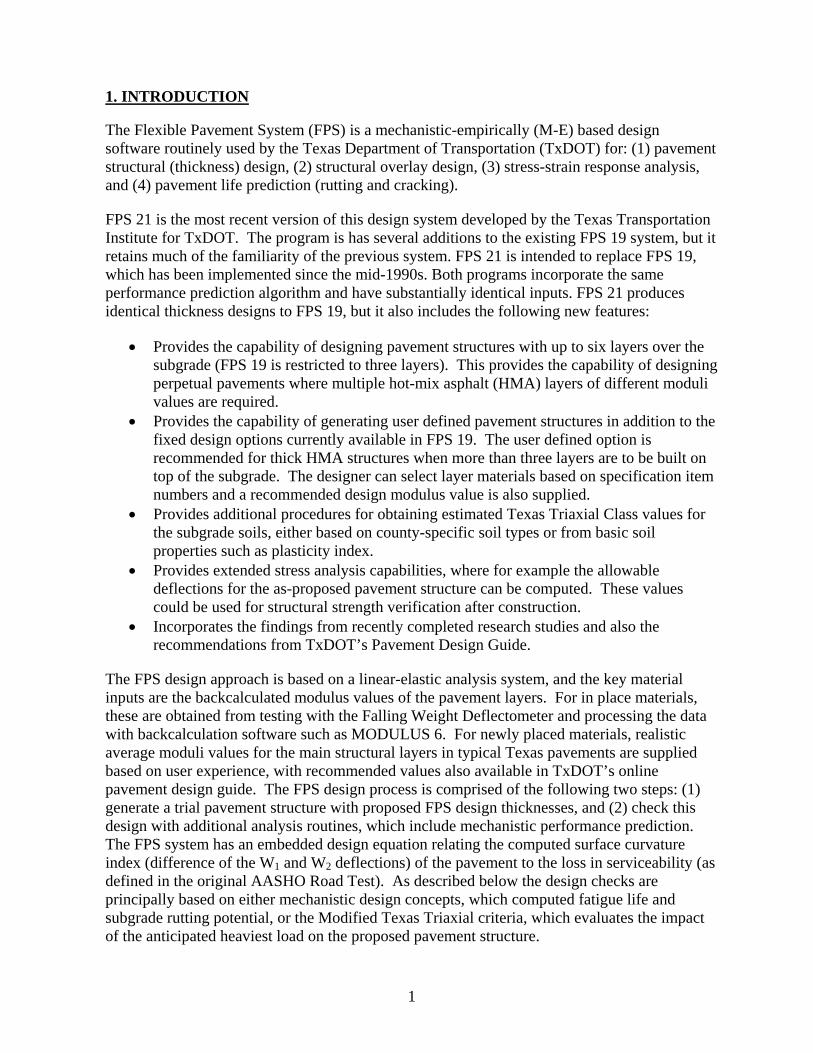
The program is supplied in an executable file called FPS21Setupmm-dd-yyyy.exe, where the effective date of the current version is included as part of the file name. Running the setup program will cause the screen shown in Figure 1 to be displayed.
3
Figure 1. Opening Screen of FPS 21 Setup Program.
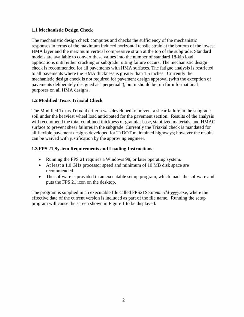
The user selects the Next button and then specifies the folder location where the FPS 21 program is to be stored. After that the screen shown in Figure 2 is displayed. To load the program, select the Start button.
Figure 2. Setup Program Screen Following Selection of Drive Storage Location.
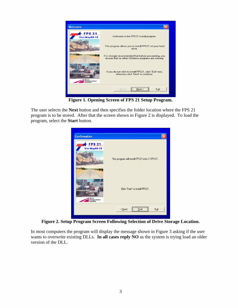
In most computers the program will display the message shown in Figure 3 asking if the user wants to overwrite existing DLLs. In all cases reply NO as the system is trying load an older version of the DLL.
4
Figure 3. Overwrite DLL Dialogue Box.
Once this is complete the FPS 21 icon will be installed onto the desktop.
5
2. NEW FEATURES IN THE FPS 21 SOFTWARE 2.1 Initiating the FPS 21 Design Software
Click on the FPS 21 icon to run the program.
2.2 Main Menu (with Version Number Date)
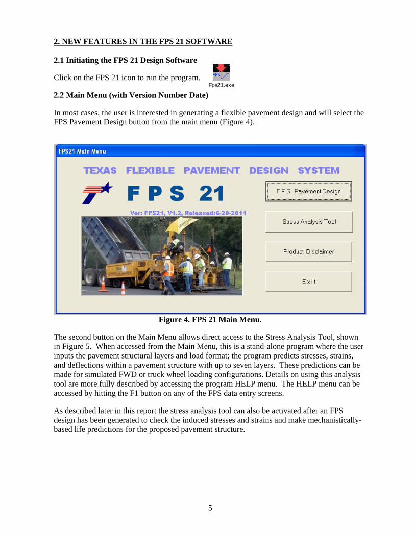
In most cases, the user is interested in generating a flexible pavement design and will select the FPS Pavement Design button from the main menu (Figure 4).
Figure 4. FPS 21 Main Menu.
The second button on the Main Menu allows direct access to the Stress Analysis Tool, shown in Figure 5. When accessed from the Main Menu, this is a stand-alone program where the user inputs the pavement structural layers and load format; the program predicts stresses, strains, and deflections within a pavement structure with up to seven layers. These predictions can be made for simulated FWD or truck wheel loading configurations. Details on using this analysis tool are more fully described by accessing the program HELP menu. The HELP menu can be accessed by hitting the F1 button on any of the FPS data entry screens.
As described later in this report the stress analysis tool can also be activated after an FPS design has been generated to check the induced stresses and strains and make mechanistically-based life predictions for the proposed pavement structure.
Fps21.exe
6
Figure 5. Stress Analysis Tool as Accessed from the Main Menu.
2.3 Setting up a Design Problem in the FPS 21 System
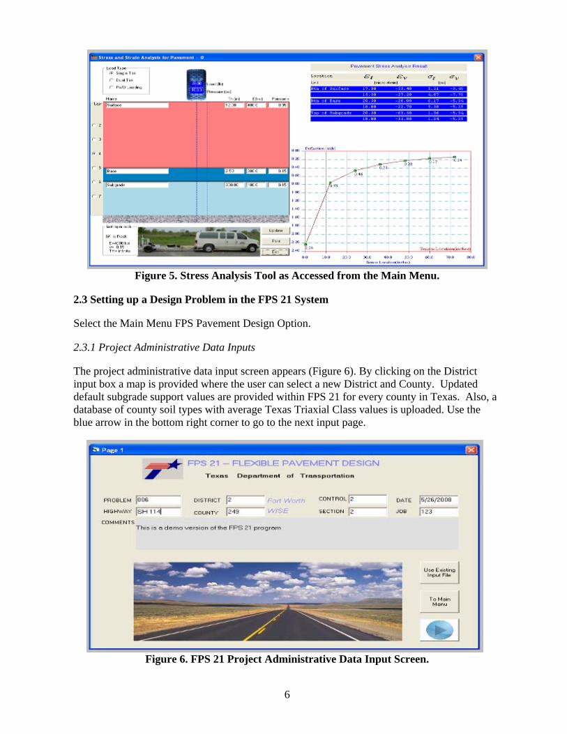
Select the Main Menu FPS Pavement Design Option.
2.3.1 Project Administrative Data Inputs
The project administrative data input screen appears (Figure 6). By clicking on the District input box a map is provided where the user can select a new District and County. Updated default subgrade support values are provided within FPS 21 for every county in Texas. Also, a database of county soil types with average Texas Triaxial Class values is uploaded. Use the blue arrow in the bottom right corner to go to the next input page.
Figure 6. FPS 21 Project Administrative Data Input Screen.
7
2.3.2 Basic Design and Traffic Inputs
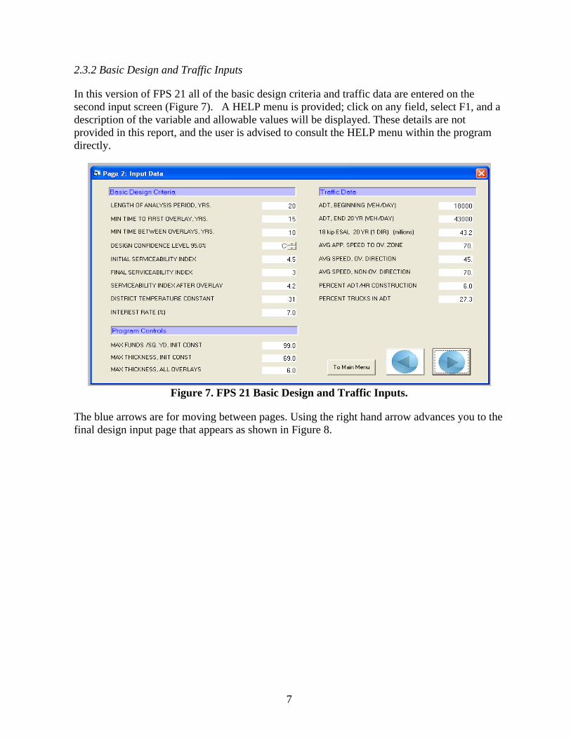
In this version of FPS 21 all of the basic design criteria and traffic data are entered on the second input screen (Figure 7). A HELP menu is provided; click on any field, select F1, and a description of the variable and allowable values will be displayed. These details are not provided in this report, and the user is advised to consult the HELP menu within the program directly.
Figure 7. FPS 21 Basic Design and Traffic Inputs.
The blue arrows are for moving between pages. Using the right hand arrow advances you to the final design input page that appears as shown in Figure 8.
8
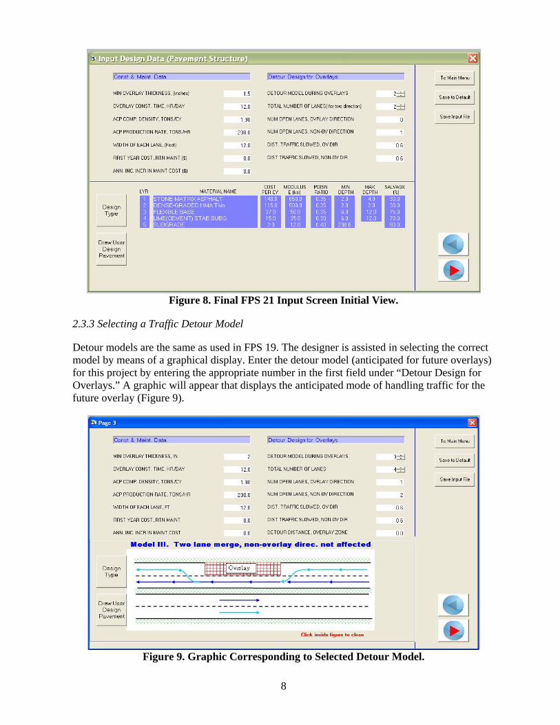
Figure 8. Final FPS 21 Input Screen Initial View.
2.3.3 Selecting a Traffic Detour Model
Detour models are the same as used in FPS 19. The designer is assisted in selecting the correct model by means of a graphical display. Enter the detour model (anticipated for future overlays) for this project by entering the appropriate number in the first field under “Detour Design for Overlays.” A graphic will appear that displays the anticipated mode of handling traffic for the future overlay (Figure 9).
Figure 9. Graphic Corresponding to Selected Detour Model.
9
Click inside the model graphic to hide the graphic and return to the original screen.
2.3.4 Selecting a Pavement Design Type
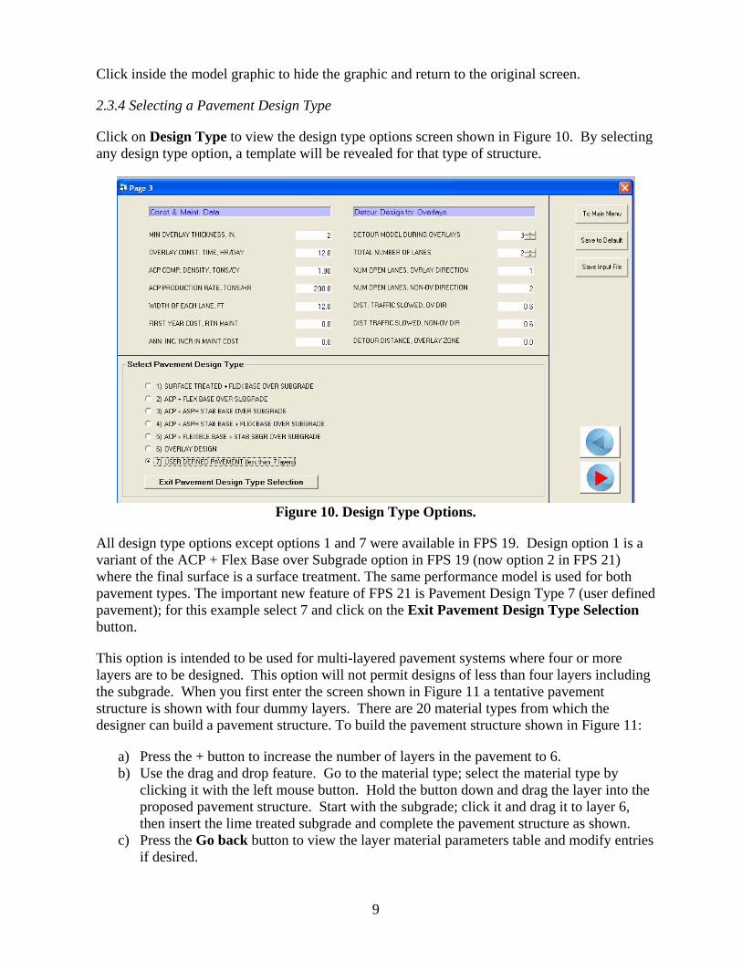
Click on Design Type to view the design type options screen shown in Figure 10. By selecting any design type option, a template will be revealed for that type of structure.
Figure 10. Design Type Options.
All design type options except options 1 and 7 were available in FPS 19. Design option 1 is a variant of the ACP + Flex Base over Subgrade option in FPS 19 (now option 2 in FPS 21) where the final surface is a surface treatment. The same performance model is used for both pavement types. The important new feature of FPS 21 is Pavement Design Type 7 (user defined pavement); for this example select 7 and click on the Exit Pavement Design Type Selection button.
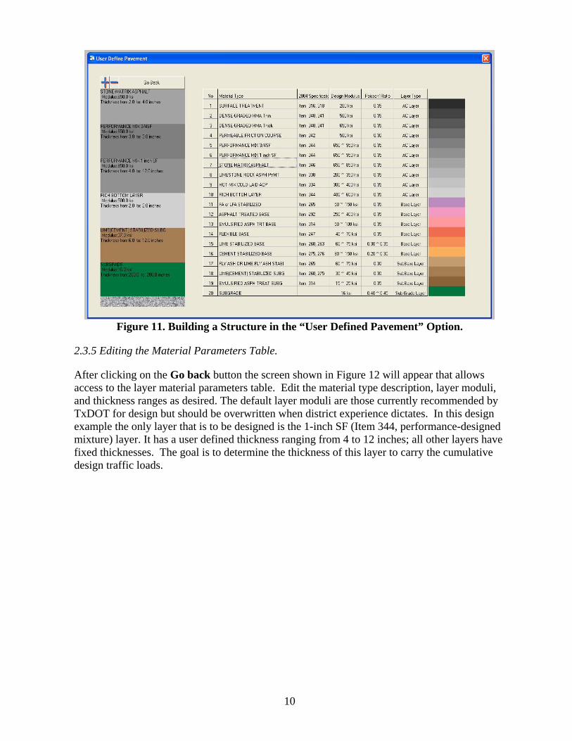
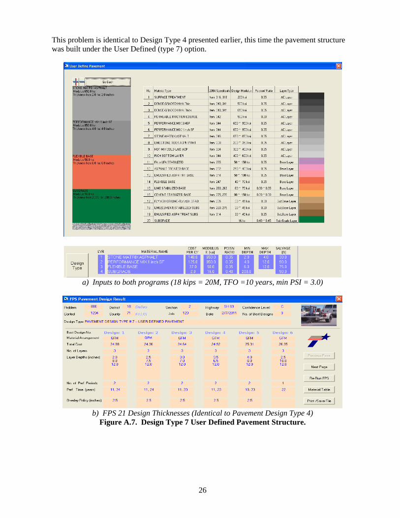
This option is intended to be used for multi-layered pavement systems where four or more layers are to be designed. This option will not permit designs of less than four layers including the subgrade. When you first enter the screen shown in Figure 11 a tentative pavement structure is shown with four dummy layers. There are 20 material types from which the designer can build a pavement structure. To build the pavement structure shown in Figure 11:
a) Press the + button to increase the number of layers in the pavement to 6. b) Use the drag and drop feature. Go to the material type; select the material type by
clicking it with the left mouse button. Hold the button down and drag the layer into the proposed pavement structure. Start with the subgrade; click it and drag it to layer 6, then insert the lime treated subgrade and complete the pavement structure as shown.
c) Press the Go back button to view the layer material parameters table and modify entries if desired.
10
Figure 11. Building a Structure in the “User Defined Pavement” Option.
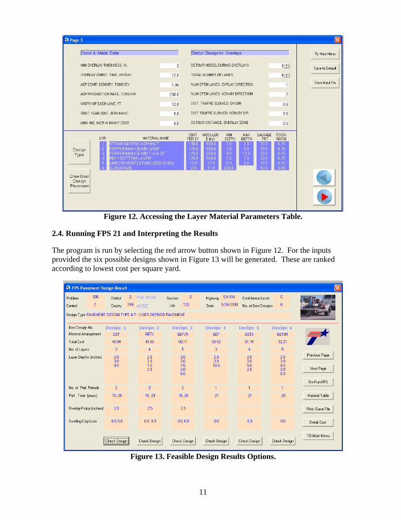
2.3.5 Editing the Material Parameters Table.
After clicking on the Go back button the screen shown in Figure 12 will appear that allows access to the layer material parameters table. Edit the material type description, layer moduli, and thickness ranges as desired. The default layer moduli are those currently recommended by TxDOT for design but should be overwritten when district experience dictates. In this design example the only layer that is to be designed is the 1-inch SF (Item 344, performance-designed mixture) layer. It has a user defined thickness ranging from 4 to 12 inches; all other layers have fixed thicknesses. The goal is to determine the thickness of this layer to carry the cumulative design traffic loads.
11
Figure 12. Accessing the Layer Material Parameters Table.
2.4. Running FPS 21 and Interpreting the Results
The program is run by selecting the red arrow button shown in Figure 12. For the inputs provided the six possible designs shown in Figure 13 will be generated. These are ranked according to lowest cost per square yard.
Figure 13. Feasible Design Results Options.
12
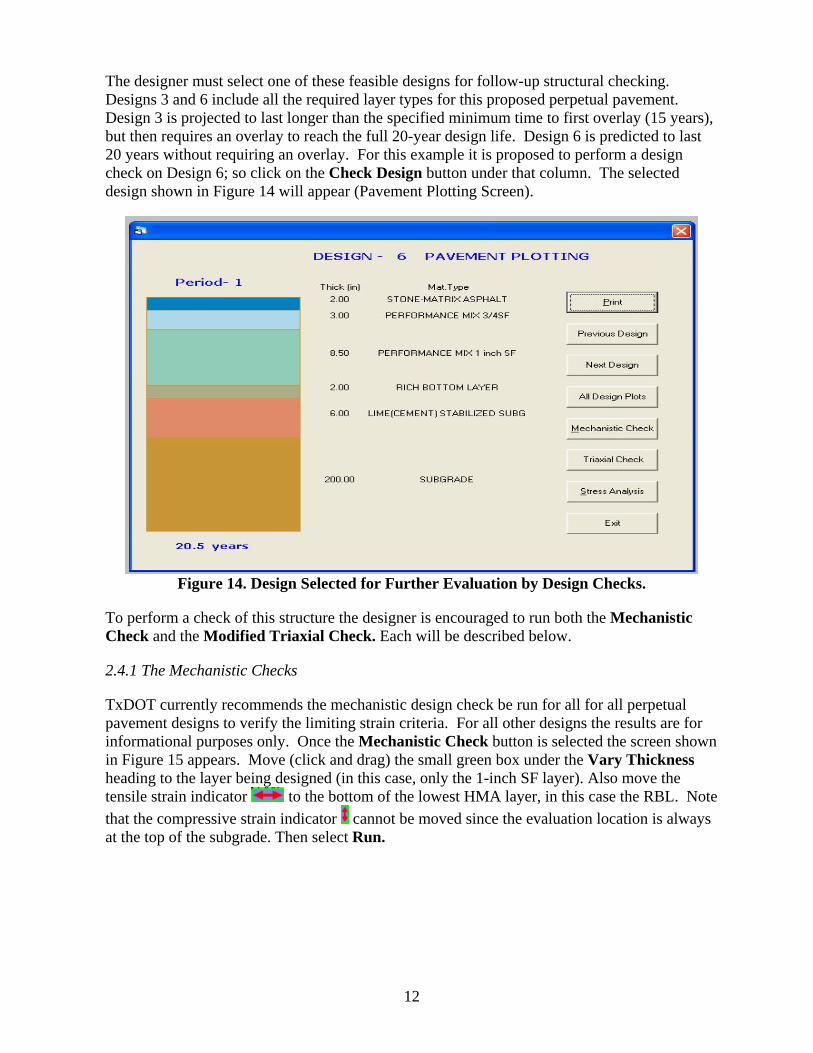
The designer must select one of these feasible designs for follow-up structural checking. Designs 3 and 6 include all the required layer types for this proposed perpetual pavement. Design 3 is projected to last longer than the specified minimum time to first overlay (15 years), but then requires an overlay to reach the full 20-year design life. Design 6 is predicted to last 20 years without requiring an overlay. For this example it is proposed to perform a design check on Design 6; so click on the Check Design button under that column. The selected design shown in Figure 14 will appear (Pavement Plotting Screen).
Figure 14. Design Selected for Further Evaluation by Design Checks.
To perform a check of this structure the designer is encouraged to run both the Mechanistic Check and the Modified Triaxial Check. Each will be described below.
2.4.1 The Mechanistic Checks
TxDOT currently recommends the mechanistic design check be run for all for all perpetual pavement designs to verify the limiting strain criteria. For all other designs the results are for informational purposes only. Once the Mechanistic Check button is selected the screen shown in Figure 15 appears. Move (click and drag) the small green box under the Vary Thickness heading to the layer being designed (in this case, only the 1-inch SF layer). Also move the tensile strain indicator to the bottom of the lowest HMA layer, in this case the RBL. Note that the compressive strain indicator cannot be moved since the evaluation location is always at the top of the subgrade. Then select Run.
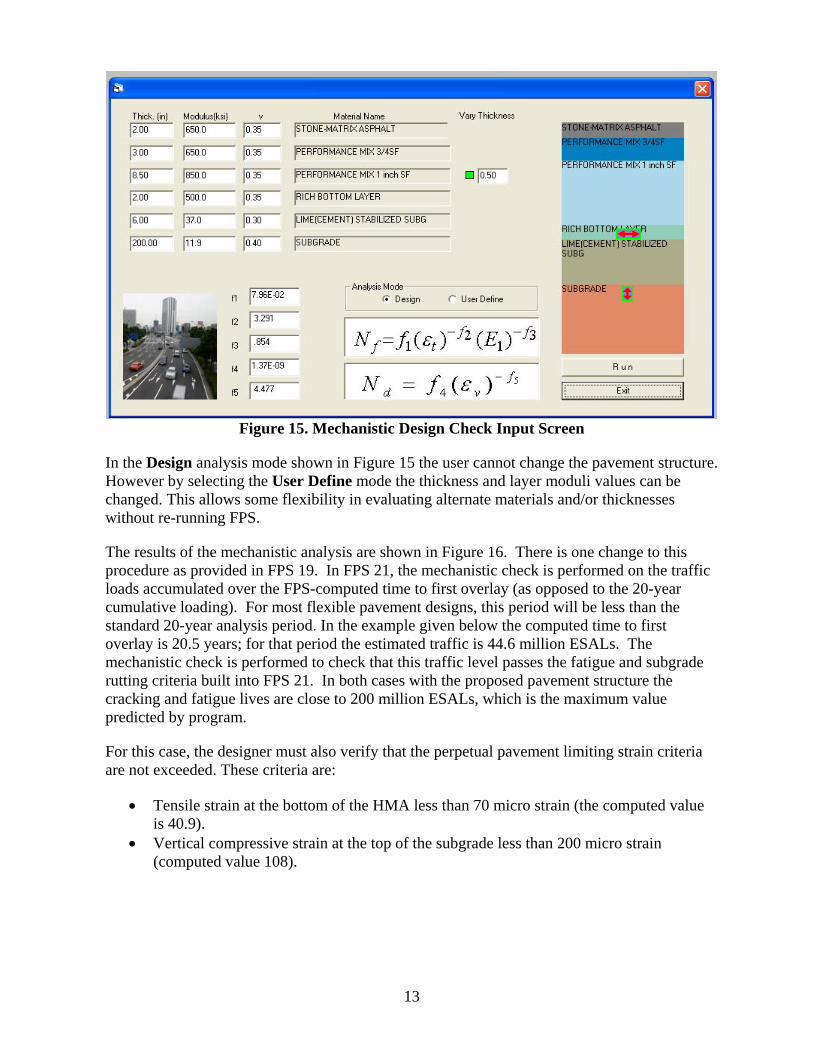
13
Figure 15. Mechanistic Design Check Input Screen
In the Design analysis mode shown in Figure 15 the user cannot change the pavement structure. However by selecting the User Define mode the thickness and layer moduli values can be changed. This allows some flexibility in evaluating alternate materials and/or thicknesses without re-running FPS.
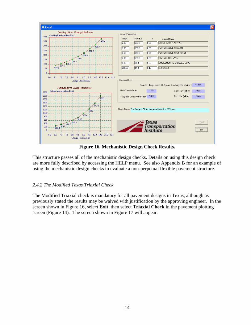
The results of the mechanistic analysis are shown in Figure 16. There is one change to this procedure as provided in FPS 19. In FPS 21, the mechanistic check is performed on the traffic loads accumulated over the FPS-computed time to first overlay (as opposed to the 20-year cumulative loading). For most flexible pavement designs, this period will be less than the standard 20-year analysis period. In the example given below the computed time to first overlay is 20.5 years; for that period the estimated traffic is 44.6 million ESALs. The mechanistic check is performed to check that this traffic level passes the fatigue and subgrade rutting criteria built into FPS 21. In both cases with the proposed pavement structure the cracking and fatigue lives are close to 200 million ESALs, which is the maximum value predicted by program.
For this case, the designer must also verify that the perpetual pavement limiting strain criteria are not exceeded. These criteria are:
• Tensile strain at the bottom of the HMA less than 70 micro strain (the computed value is 40.9).
• Vertical compressive strain at the top of the subgrade less than 200 micro strain (computed value 108).
14
Figure 16. Mechanistic Design Check Results.
This structure passes all of the mechanistic design checks. Details on using this design check are more fully described by accessing the HELP menu. See also Appendix B for an example of using the mechanistic design checks to evaluate a non-perpetual flexible pavement structure.
2.4.2 The Modified Texas Triaxial Check
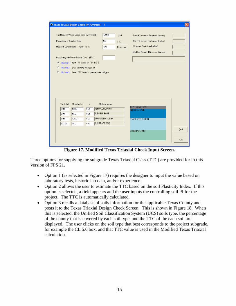
The Modified Triaxial check is mandatory for all pavement designs in Texas, although as previously stated the results may be waived with justification by the approving engineer. In the screen shown in Figure 16, select Exit, then select Triaxial Check in the pavement plotting screen (Figure 14). The screen shown in Figure 17 will appear.
15
Figure 17. Modified Texas Triaxial Check Input Screen.
Three options for supplying the subgrade Texas Triaxial Class (TTC) are provided for in this version of FPS 21.
• Option 1 (as selected in Figure 17) requires the designer to input the value based on laboratory tests, historic lab data, and/or experience.
• Option 2 allows the user to estimate the TTC based on the soil Plasticity Index. If this option is selected, a field appears and the user inputs the controlling soil PI for the project. The TTC is automatically calculated.
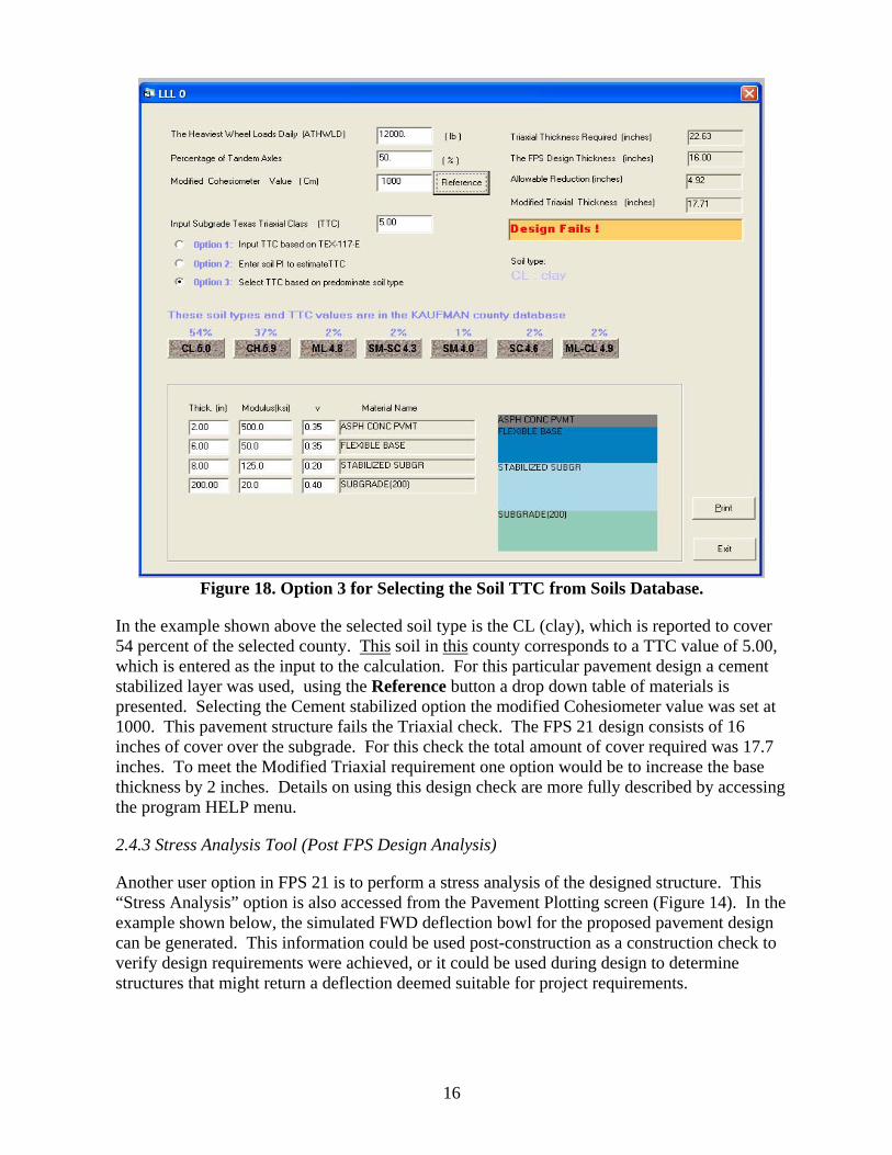
• Option 3 recalls a database of soils information for the applicable Texas County and posts it to the Texas Triaxial Design Check Screen. This is shown in Figure 18. When this is selected, the Unified Soil Classification System (UCS) soils type, the percentage of the county that is covered by each soil type, and the TTC of the each soil are displayed. The user clicks on the soil type that best corresponds to the project subgrade, for example the CL 5.0 box, and that TTC value is used in the Modified Texas Triaxial calculation.
16
Figure 18. Option 3 for Selecting the Soil TTC from Soils Database.
In the example shown above the selected soil type is the CL (clay), which is reported to cover 54 percent of the selected county. This soil in this county corresponds to a TTC value of 5.00, which is entered as the input to the calculation. For this particular pavement design a cement stabilized layer was used, using the Reference button a drop down table of materials is presented. Selecting the Cement stabilized option the modified Cohesiometer value was set at 1000. This pavement structure fails the Triaxial check. The FPS 21 design consists of 16 inches of cover over the subgrade. For this check the total amount of cover required was 17.7 inches. To meet the Modified Triaxial requirement one option would be to increase the base thickness by 2 inches. Details on using this design check are more fully described by accessing the program HELP menu.
2.4.3 Stress Analysis Tool (Post FPS Design Analysis)
Another user option in FPS 21 is to perform a stress analysis of the designed structure. This “Stress Analysis” option is also accessed from the Pavement Plotting screen (Figure 14). In the example shown below, the simulated FWD deflection bowl for the proposed pavement design can be generated. This information could be used post-construction as a construction check to verify design requirements were achieved, or it could be used during design to determine structures that might return a deflection deemed suitable for project requirements.
17
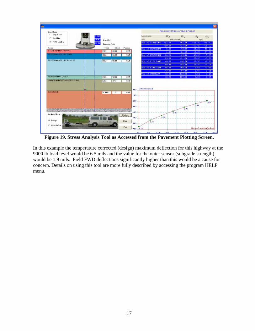
Figure 19. Stress Analysis Tool as Accessed from the Pavement Plotting Screen.
In this example the temperature corrected (design) maximum deflection for this highway at the 9000 lb load level would be 6.5 mils and the value for the outer sensor (subgrade strength) would be 1.9 mils. Field FWD deflections significantly higher than this would be a cause for concern. Details on using this tool are more fully described by accessing the program HELP menu.


19
APPENDIX A. THICKNESS DESIGN COMPARISON: FPS 19 VERSUS FPS 21 FOR
COMPARABLE PAVEMENT DESIGN TYPES
This appendix shows examples of comparable design types run in both FPS 19 and FPS 21.
In all cases the generated thickness designs are identical.
In the following figures, Figure a) shows the identical inputs supplied to both programs, Figure b) shows the FPS 21 thickness design results, and Figure c) shows the FPS 19 comparable thickness design results.
20
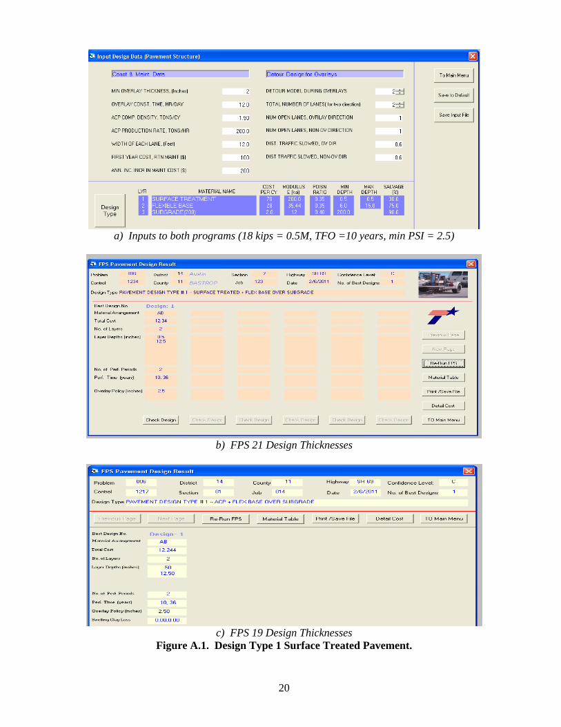
a) Inputs to both programs (18 kips = 0.5M, TFO =10 years, min PSI = 2.5)
b) FPS 21 Design Thicknesses
c) FPS 19 Design Thicknesses
Figure A.1. Design Type 1 Surface Treated Pavement.
21
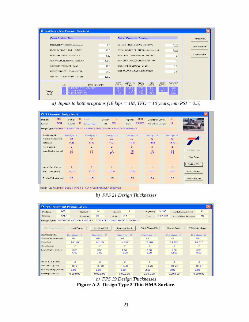
a) Inputs to both programs (18 kips = 1M, TFO = 10 years, min PSI = 2.5)
b) FPS 21 Design Thicknesses
c) FPS 19 Design Thicknesses
Figure A.2. Design Type 2 Thin HMA Surface.
22
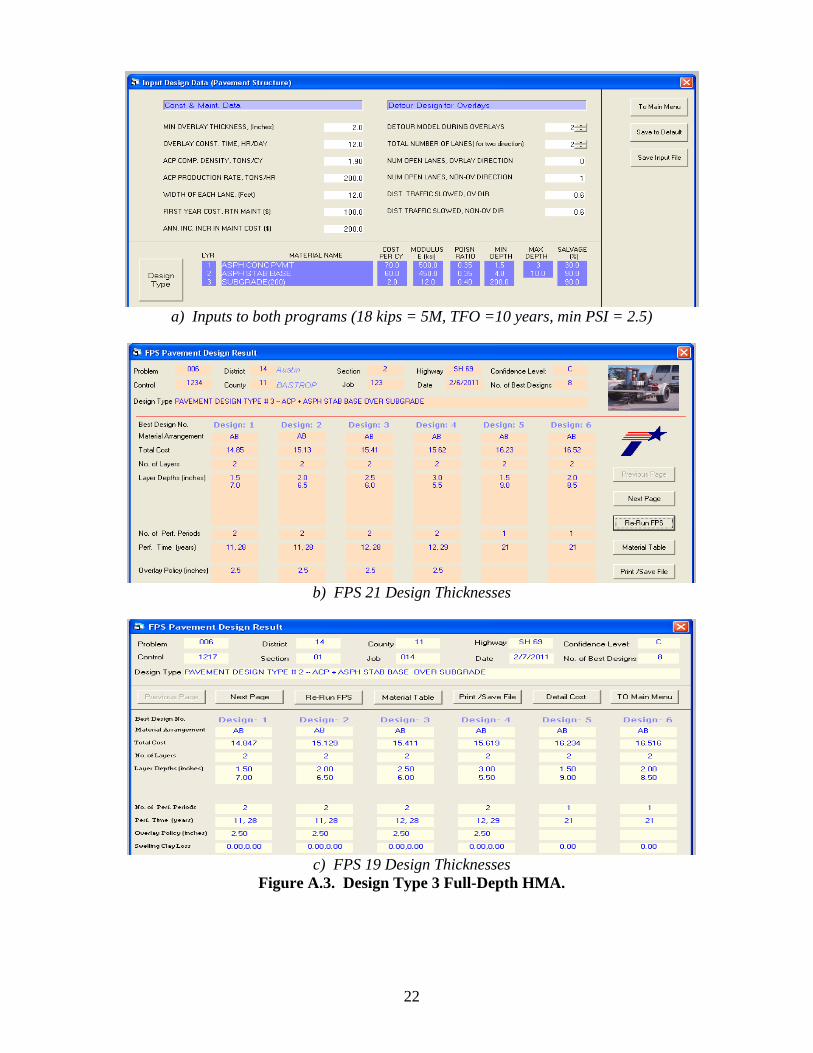
a) Inputs to both programs (18 kips = 5M, TFO =10 years, min PSI = 2.5)
b) FPS 21 Design Thicknesses
c) FPS 19 Design Thicknesses
Figure A.3. Design Type 3 Full-Depth HMA.
23
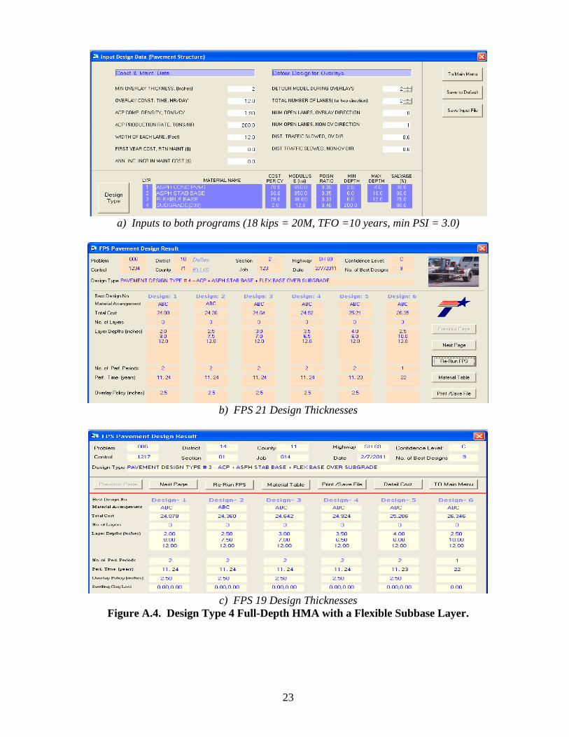
a) Inputs to both programs (18 kips = 20M, TFO =10 years, min PSI = 3.0)
b) FPS 21 Design Thicknesses
c) FPS 19 Design Thicknesses
Figure A.4. Design Type 4 Full-Depth HMA with a Flexible Subbase Layer.
24
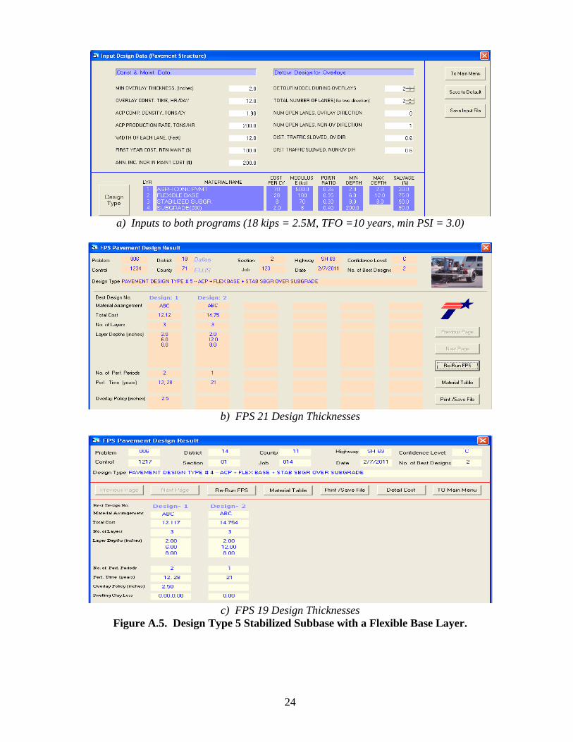
a) Inputs to both programs (18 kips = 2.5M, TFO =10 years, min PSI = 3.0)
b) FPS 21 Design Thicknesses
c) FPS 19 Design Thicknesses
Figure A.5. Design Type 5 Stabilized Subbase with a Flexible Base Layer.
25
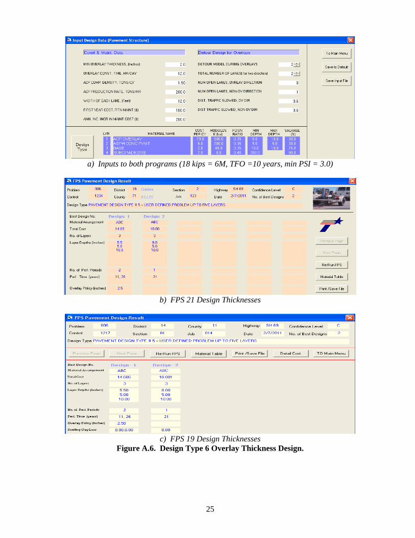
a) Inputs to both programs (18 kips = 6M, TFO =10 years, min PSI = 3.0)
b) FPS 21 Design Thicknesses
c) FPS 19 Design Thicknesses
Figure A.6. Design Type 6 Overlay Thickness Design.
26
This problem is identical to Design Type 4 presented earlier, this time the pavement structure was built under the User Defined (type 7) option.
a) Inputs to both programs (18 kips = 20M, TFO =10 years, min PSI = 3.0)
b) FPS 21 Design Thicknesses (Identical to Pavement Design Type 4)
Figure A.7. Design Type 7 User Defined Pavement Structure.
27
APPENDIX B. MECHANISTIC CHECKS:
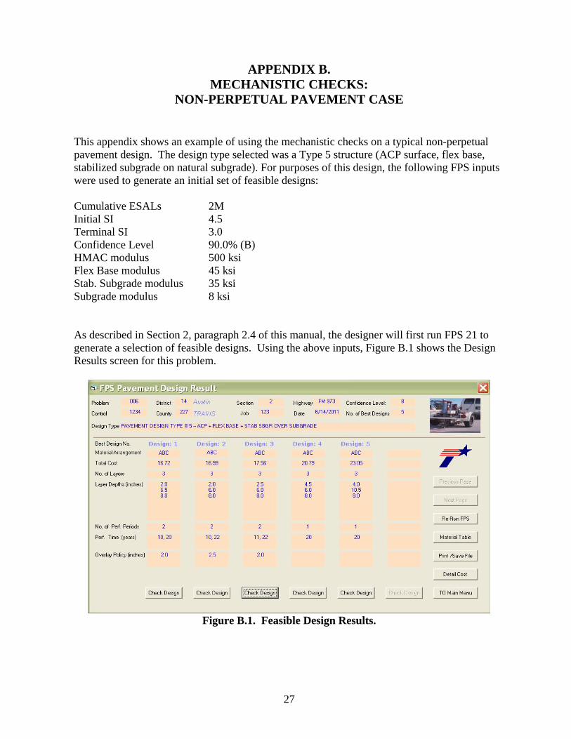
NON-PERPETUAL PAVEMENT CASE This appendix shows an example of using the mechanistic checks on a typical non-perpetual pavement design. The design type selected was a Type 5 structure (ACP surface, flex base, stabilized subgrade on natural subgrade). For purposes of this design, the following FPS inputs were used to generate an initial set of feasible designs: Cumulative ESALs 2M Initial SI 4.5 Terminal SI 3.0 Confidence Level 90.0% (B) HMAC modulus 500 ksi Flex Base modulus 45 ksi Stab. Subgrade modulus 35 ksi Subgrade modulus 8 ksi As described in Section 2, paragraph 2.4 of this manual, the designer will first run FPS 21 to generate a selection of feasible designs. Using the above inputs, Figure B.1 shows the Design Results screen for this problem.
Figure B.1. Feasible Design Results.
28
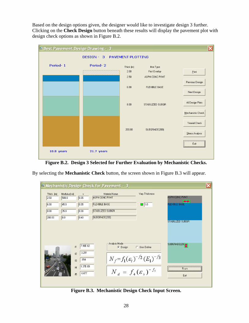
Based on the design options given, the designer would like to investigate design 3 further. Clicking on the Check Design button beneath these results will display the pavement plot with design check options as shown in Figure B.2.
Figure B.2. Design 3 Selected for Further Evaluation by Mechanistic Checks.
By selecting the Mechanistic Check button, the screen shown in Figure B.3 will appear.
Figure B.3. Mechanistic Design Check Input Screen.
29
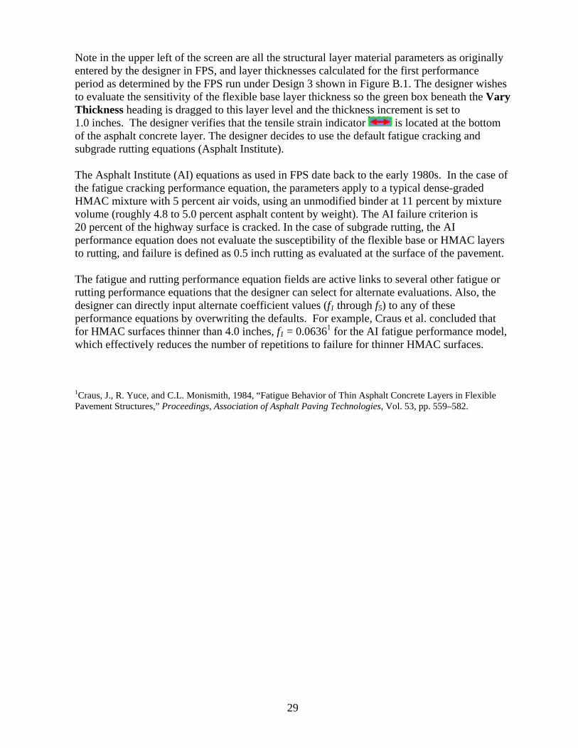
Note in the upper left of the screen are all the structural layer material parameters as originally entered by the designer in FPS, and layer thicknesses calculated for the first performance period as determined by the FPS run under Design 3 shown in Figure B.1. The designer wishes to evaluate the sensitivity of the flexible base layer thickness so the green box beneath the Vary Thickness heading is dragged to this layer level and the thickness increment is set to 1.0 inches. The designer verifies that the tensile strain indicator is located at the bottom of the asphalt concrete layer. The designer decides to use the default fatigue cracking and subgrade rutting equations (Asphalt Institute). The Asphalt Institute (AI) equations as used in FPS date back to the early 1980s. In the case of the fatigue cracking performance equation, the parameters apply to a typical dense-graded HMAC mixture with 5 percent air voids, using an unmodified binder at 11 percent by mixture volume (roughly 4.8 to 5.0 percent asphalt content by weight). The AI failure criterion is 20 percent of the highway surface is cracked. In the case of subgrade rutting, the AI performance equation does not evaluate the susceptibility of the flexible base or HMAC layers to rutting, and failure is defined as 0.5 inch rutting as evaluated at the surface of the pavement. The fatigue and rutting performance equation fields are active links to several other fatigue or rutting performance equations that the designer can select for alternate evaluations. Also, the designer can directly input alternate coefficient values (f1 through f5) to any of these performance equations by overwriting the defaults. For example, Craus et al. concluded that for HMAC surfaces thinner than 4.0 inches, f1 = 0.06361 for the AI fatigue performance model, which effectively reduces the number of repetitions to failure for thinner HMAC surfaces. 1Craus, J., R. Yuce, and C.L. Monismith, 1984, “Fatigue Behavior of Thin Asphalt Concrete Layers in Flexible Pavement Structures,” Proceedings, Association of Asphalt Paving Technologies, Vol. 53, pp. 559–582.
30
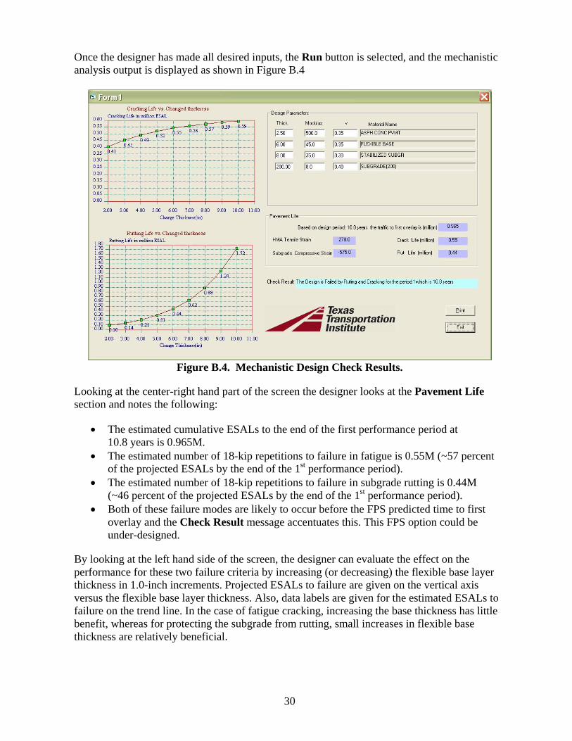
Once the designer has made all desired inputs, the Run button is selected, and the mechanistic analysis output is displayed as shown in Figure B.4
Figure B.4. Mechanistic Design Check Results.
Looking at the center-right hand part of the screen the designer looks at the Pavement Life section and notes the following:
• The estimated cumulative ESALs to the end of the first performance period at 10.8 years is 0.965M.
• The estimated number of 18-kip repetitions to failure in fatigue is 0.55M (~57 percent of the projected ESALs by the end of the 1st performance period).
• The estimated number of 18-kip repetitions to failure in subgrade rutting is 0.44M (~46 percent of the projected ESALs by the end of the 1st performance period).
• Both of these failure modes are likely to occur before the FPS predicted time to first overlay and the Check Result message accentuates this. This FPS option could be under-designed.
By looking at the left hand side of the screen, the designer can evaluate the effect on the performance for these two failure criteria by increasing (or decreasing) the flexible base layer thickness in 1.0-inch increments. Projected ESALs to failure are given on the vertical axis versus the flexible base layer thickness. Also, data labels are given for the estimated ESALs to failure on the trend line. In the case of fatigue cracking, increasing the base thickness has little benefit, whereas for protecting the subgrade from rutting, small increases in flexible base thickness are relatively beneficial.
31
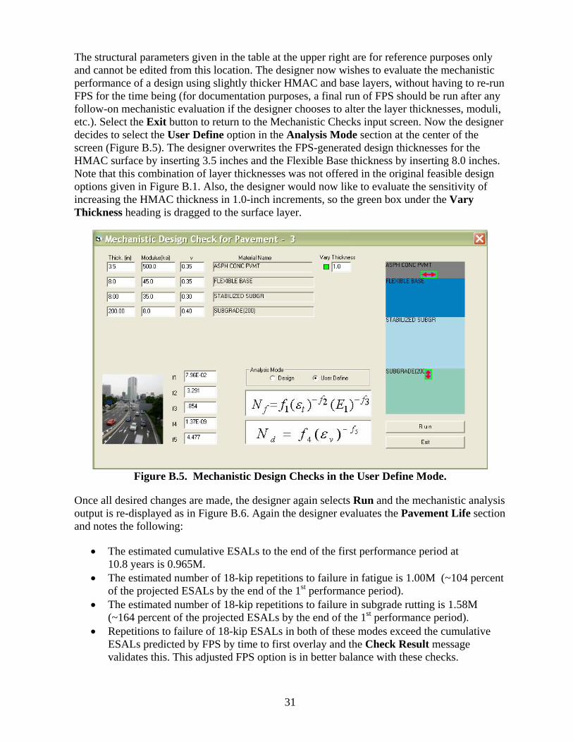
The structural parameters given in the table at the upper right are for reference purposes only and cannot be edited from this location. The designer now wishes to evaluate the mechanistic performance of a design using slightly thicker HMAC and base layers, without having to re-run FPS for the time being (for documentation purposes, a final run of FPS should be run after any follow-on mechanistic evaluation if the designer chooses to alter the layer thicknesses, moduli, etc.). Select the Exit button to return to the Mechanistic Checks input screen. Now the designer decides to select the User Define option in the Analysis Mode section at the center of the screen (Figure B.5). The designer overwrites the FPS-generated design thicknesses for the HMAC surface by inserting 3.5 inches and the Flexible Base thickness by inserting 8.0 inches. Note that this combination of layer thicknesses was not offered in the original feasible design options given in Figure B.1. Also, the designer would now like to evaluate the sensitivity of increasing the HMAC thickness in 1.0-inch increments, so the green box under the Vary Thickness heading is dragged to the surface layer.
Figure B.5. Mechanistic Design Checks in the User Define Mode.
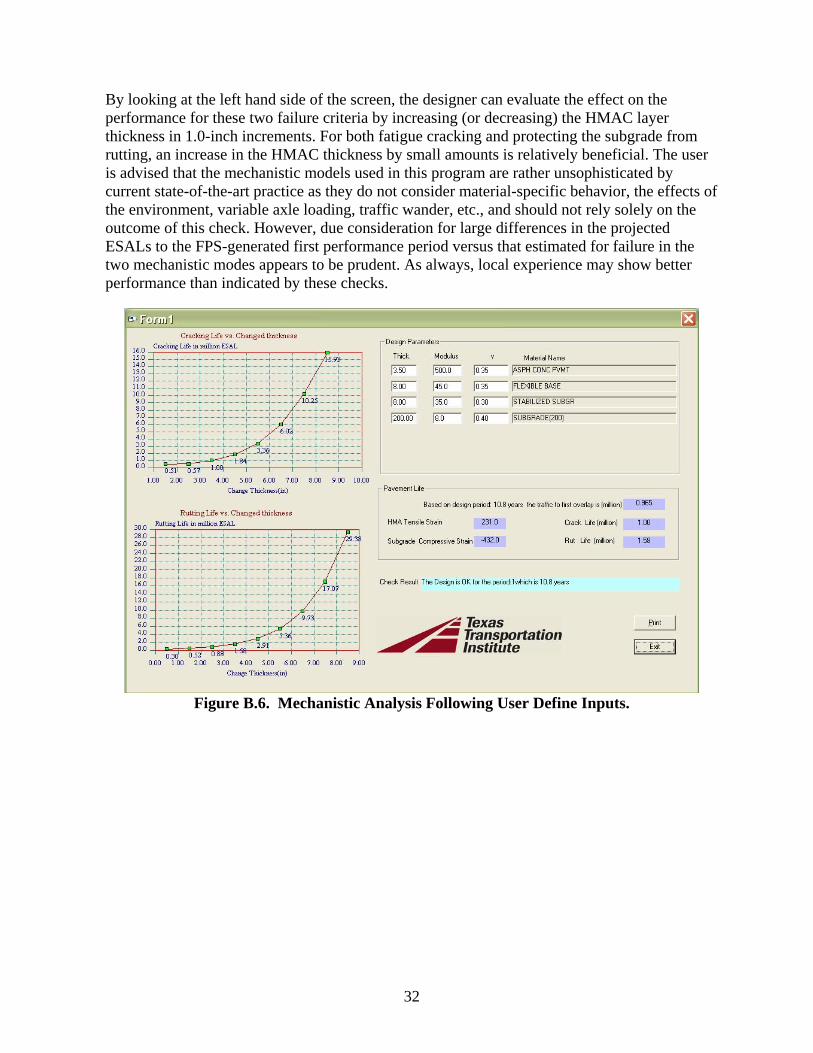
Once all desired changes are made, the designer again selects Run and the mechanistic analysis output is re-displayed as in Figure B.6. Again the designer evaluates the Pavement Life section and notes the following:
• The estimated cumulative ESALs to the end of the first performance period at 10.8 years is 0.965M.
• The estimated number of 18-kip repetitions to failure in fatigue is 1.00M (~104 percent of the projected ESALs by the end of the 1st performance period).
• The estimated number of 18-kip repetitions to failure in subgrade rutting is 1.58M (~164 percent of the projected ESALs by the end of the 1st performance period).
• Repetitions to failure of 18-kip ESALs in both of these modes exceed the cumulative ESALs predicted by FPS by time to first overlay and the Check Result message validates this. This adjusted FPS option is in better balance with these checks.
32
By looking at the left hand side of the screen, the designer can evaluate the effect on the performance for these two failure criteria by increasing (or decreasing) the HMAC layer thickness in 1.0-inch increments. For both fatigue cracking and protecting the subgrade from rutting, an increase in the HMAC thickness by small amounts is relatively beneficial. The user is advised that the mechanistic models used in this program are rather unsophisticated by current state-of-the-art practice as they do not consider material-specific behavior, the effects of the environment, variable axle loading, traffic wander, etc., and should not rely solely on the outcome of this check. However, due consideration for large differences in the projected ESALs to the FPS-generated first performance period versus that estimated for failure in the two mechanistic modes appears to be prudent. As always, local experience may show better performance than indicated by these checks.
Figure B.6. Mechanistic Analysis Following User Define Inputs.