Embed Size (px)
Citation preview

Powder Teciznology, 39 (1984) 29 - 40 29
Flow of Granular Material Through a Plane Hopper
R. L. MICHALOWSKI*
University of Minnesota. Department of Civil and 1 ::i.zeral Engineering. 500 PZLC~XQF Era-~%?. S.E.. .llinneepo?is.
MIV 55455 (U_S_A_)
(Received May 23.1983;revised for October 10, 1983)
SUMMARY
TWs paper presents some experimental results of an investigation of flow patterns of sand in a plane. wedge-shaped hopper model and aZso an approach to a theoretical descrip- tion of the discharge process_ A non-steady discontinuous velocity field was observed in the expertments- TJelocity discontinuities were traced during the process of discharge using the stereophotographic technique_ Com- plementary information about the density uariations of the material during discharge was obtained from X-ray pictures and from ultrasonic measurements.
Theoretical description of the velocity field is restricted to the advanced flow. which, as demonstrated in the experiments, can be treated approximately as a pseudo-steady process. An approach based upon the plane plastic flow theory of incompressible Coulomb material is applied. The theoretical solution for the velocity field is compared with some of the experimental results.
INTRODUCTION
The paper consists of two parts. In the first one, the flow through a plane, wedge-shaped hopper model is experimentally investigated_ The stereophotographic technique is used in order to determine the location of any disturbances in the velocity field. Variation of the density of the material during flow is described making use of unpublished results of X-ray experiments performed by A_ Drescher at the University of Cambridge in 1976_ The ultrasonic method of density
The aim of esperiments presented in this paper is to determine t-he flow patterns (the rupture surfaces in particular) during the entire discharge process rather than the velocity field at one particular moment of the fiOW_
*University of h5nnesota, on sabbatical leave from the Technical University of Poznaii, Poland_
Three different approaches to a theoretical description of the velocity distribution in hoppers can be distinguished_ The first one is based on plasticity theory, in which the stress distribution is first calculated and then the boundary problem for velocities solved (Shield [7, S], Jenike (91, Spencer [lo], Pariseau El]). The second approach, presented by Drescher, Cousens and Bransby [ 111, is also based on plasticity theory; however, the kinematically admissible velocity field is
0032-5910/84]S3_00 0 Elsevier Sequoia/Printed in The Netherlands
measurement is also used in order to obtain some quantitative results The second part of the paper is devoted to mathematical descrip- tion of the advanced stage of flow, based on the plane plastic flow theory-
Experiments on gravitational flov.- of granular material through hoppers have been carried out by many investigators: Tdeau [ 11, Blair-Fish and Bransby (2, 33 T Lee, Cow-in and Templeton [4], Nedderman and Tiiziin [S, 63, and others. A large number of experiments have shown that narrow zones of large deformation, called here after Blair-Fish and Bransby [ 23, the rupture surfaces, occur within the floxring regions. Large shearing strains are accompanied by dilation of the material_ Velocities of the particles experience a rapid variation across the rupture surfaces, hence they are often interpreted as velocity discontinuities. No discont.inuities in the velocity field were observed by Kedderman and Tiizfin [S]: however, their experiments differ markedly from those of Pariseau [I], Bransby and Blair-Fish [ 2,3] 1 and also from those presented in this paper_

30
obtained without predicting the stress field. This is possible by assuming a priori the pattern of the velocity field. The third ap- proach involves a purely kirematic model, developed mainly by Litwiniszyn 1123 and Mullins [x3,14], and successfully applied to the problem of flow through hoppers by Nedderman and Tiiziin [5,6]. This model was suggested by Nedderman and Tiiziin [5] solely for steady Sow of a dilated material.
in the present paper, the first approach is applied_ The radial stress field [9] is adopted here and then the velocity boundary problem solved for boundary conditions defined from the experiments. Referring to the experi- mental results, it is suggested that pseudo- steady flow occurs in the advanced stage of flow_
Theoretical description based on similar assumptions was given earlier by Pariseau [l] _ However, the principal strain-rate trajectories were determined by Pariseau experimentally, and the problem for velocities was solved for boundary conditions different from those proposed here. The objective of the theoreti- cal investigation presented in this paper was to describe the flow without a large number of experimental data. Experimental results were used, however, in order to determine the boundary conditions_
HOPPER MODEL AND EXPERIMENTAL TECH- NIQUES
The experiments presented here, except for the X-ray investigations, were performed on a model of the plane hopper built in the Institute of Fundamental Technological Research in Warsaw. The hopper model consisted of two wooden bars (hopper walls), each 4 cm thick and 85 cm long, placed between two glass sheets. Some introductory experiments were compared with those performed on models with larger ratios of the thickness to the distance between the hopper walls (e.g. 13, 15, IS]), in which the flow patterns were investigated by means of the X-ray technique_ The results allow one to believe that in the experiments presented in this paper the side friction from the glass did not influence the flow patterns in any significant way. The inclination of the walls
and the width of the outlet could be adjusted according to the program of esperiments. Sand with particle diameters in the range of 0.25 - 1.75 mm was used in all esperiments. Initial density pc of the material placed in the hopper for different esperiments varied from 1.55 to_1.70 X lo3 kg/m3. In order to produce low and high wall friction, the hopper walls were covered with oil paint (wall friction angle 9, = 11”) or sand paper ($,\_ = 25”) In experiments where the density was measured by means of the ultrasonic method, the glass sheets were replaced by Plesiglas and the ultrasonic heads were inserted into the holes drilled into the Plesiglas. X-ray esperiments were performed in a similar Plesiglas hopper model built in Cambridge.
Stereo-photographic technique Stereo-photogrammetry provides a power-
ful method for measuring planar displacement (or velocity) fields. The method was discussed in detail by Butterfield, Harkness and Andrawes [ 173 _ The stereo-photographic technique seems to be particularly suitable for investigating any disturbance in the velocity field. Here it is expected to supply infor- mation about propagation of the rupture surfaces_ It is clearly understood that the stereoscopic image obtained from the pictures of t.he material flowing through the hopper, in time t and t + 6t, is related not only to the velocity field at time t but also, due to non- steady flow, to the variat.ion of the velocity field in the time increment St_ This variation can usually be neglected for the flow regions where the velocity field is continuous and for small increments 6t. Finally, the field of displacements can be interpreted as a velocity field. The stereoscopic image of displacements has to be interpreted more carefully, however, if the discontinuities appear in the velocity field. The discontinuity in a steady velocity field in a stereoscopic image is seen as a ‘slope’ rather than a vertical ‘fault’_ The width of the ‘slope’ depends on the time increment, but its inclination does not. In the real case of flow of granular material through hoppers, the discontinuities move with their own velocities. It is possible to define the velocity of propagation of the discontinuity lines using the stereophotographic technique together with some direct measurements on the photographs.

31
Although the stereo-photographic method was used mainly to trace the development of the rupture surfaces, it was also used to identify the selected particles on the photo- graphs, so the displacement vectors could be obtained from direct measurements.
Radiographic technique The radiographic technique was used in
order to investigate a variation of density of the material during flow through the hopper model The X-radiographs were taken while the flow was stopped. Due to variation of X-ray attenuation with the density of the material, the X-ray shadow shows clearly the areas of dense (dark) and loose (light) material. The radiographic technique was applied earlier to the problem of flow through hoppers by many investigators [2,4,15,16]. The X-ray technique was used here solely to investigate the density; however, it can be also used to measure strains 118 ]_
density was computed from one empirical relation between density and velocity-
Since the ultrasonic t.echnique of density measurement requires permanent location of the ultrasonic heads, the density of some characteristic areas cannot be traced during unsteady flow through the hopper. The measurements can be considered as reliable if the density of the area covered by the heads is uniform_ Otherwise, the digitally regist.ered time of wave propagation (across the model) corresponds to that part of the material (covered by the ultrasonic heads) in which the velocity of wave propagation is the highest For the tested material, in the range of ajj/3 from 0 to about 9 kN/m’, the ve1ocit.y was higher for lower densities (as opposed to cases where 0,</3 > 9 kN/m’)_ Hence, in the esperi- ments presented, the ultrasonic method underestimates the density if it is non- uniform.
The technique itself and obtained empirical relations were discussed in detail by Drescher
i_Utrasonic technique of density measurement The ultrasonic technique was used on a
and Michalowski 120: _
small scale to obtain some supplementary quantitative results of density variation_ This technique uses the relation between the velocity of a longitudinal elastic wave and the density of the material. The time during which the wave crossed the material placed in the hopper model was measured (for stopped flow) and then converted into the wave velocity, and finally the density of the materi- al was computed from the empirical relation between the density and the wave velocity_ The velocity of wave propagation, however, is also a function of stress state, moisture content and grain characteristics, such as the diameter of particles, number of contacts per particle and the mechanical properties of the particles [19]_ Therefore the empirical relations were obtained from a number of tests in which the variables considered were density and confining pressure oji/3_ All experiments were performed under the same humidity conditions. It was found for a given sand that for the confining lxessure oii/3 changing from 0 to about ‘i. l&I/m’, the influence of this pressure on wave velocity is negligible. Estimations of the stress state within the material placed in the hopper model gave the value of aii/3 not exceeding 2 kN/m’_ Hence, for all experiments, the
ESPERINENTAL RESULTS
The aim of the experiments was to describe flow patterns during the whole cycle of emptying the hopper. Although various experimental techniques were used, the overall picpare will be reported in this section-
TKO stages of the flow of granular material through plane hoppers can be distinguished: initial and advanced_ Unsteady flax occurs in both of them_ It will be show-n, however, that the advanced flow can be interpreted as a pseudo-steady process and a fairly simple approsimate theoretical description can be applied.
Initial flow Two different mechanisms may appear in
the initial stage of flow_ In the first one, called here t.he mass mechanism, after the outlet of the hopper is open, two narrow-, usually symmetrical, curvilinear zones of large deformation (rupture surfaces) occur in the neighbourhood of the outlet. The two rupture surfaces propagate gradually upward, cross in the vicinity of the asis of symmetry of the hopper and then reach the walls_ The nest pair of rupture surfaces starts then to grow’
32
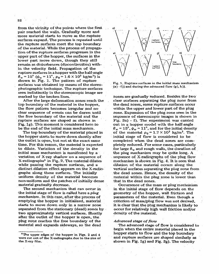
from the vicinity of the points where the first pair reached the walls. Gradually more and more material starts to move as the rupture surfaces expand. The process is repeated until the rupture surfaces meet the top boundary of the material_ While the process of propaga- tion of the rupture surfaces progresses in the upper part of the hopper, the surfaces in the lower part move down, though they still remain as disturbances (discontinuities) with- in the velocity field_ Propagation of the rupture surfaces in a hopper with the half-angle O,V = 15” (9, = ll”, p. = 1.6 X lo3 kg/m3) is shown in Fig. 1. The pattern of rupture surfaces was obtained by means of the stereo- photographic technique_ The rupture surfaces seen indistinctly in the stereoscopic image are marked by the broken lines.
After the large deformation zones reach the top boundary of the material in the hopper, the flow pattern becomes irregular and no clear sequence of events can be drawn until the free boundary of the material and the rupture surfaces are shaped as shown in Fig. lg). This moment is considered here to be the end of the initial mass mechanism_
The top boundary of the material placed in the hopper starts to move down shortly after the outlet is open, but not at the exact same time. For this reason, the material is espected to dilate. Variation of the density in the initial mass mechanism is manifested by a variation of X-ray shadow on a sequence of X-radiograph? in Fig_ 2_ The material dilates while passing the rupture surfaces, and a distinct dilation effect appears on the X-radio- graphs along these surfaces_ The initially uniform density of the material becomes non-uniform and the patches of initially dense material gradually decrease_
The second mechanism that can occur in the initial stage of flow is called here a plug mechanism. In this case, after the process of emptying the hopper in initialized, material starts to move down only in a narrow zone separated from the stationary (dead) zones by two approximately vertical surfaces_ Shortly after the outlet of the hopper is open, the plug zone reaches the free boundary of the material and expands sideways, so the dead
%l?he upper edges of the hopper in Figs. 2 and 4 were cut out of the X-radiographs due to the size of the X-ray film.
Fig. 1. Rupture surfaces in the initial mass mechanism (a) - f)) and during the advanced flow (g), h)).
zones are gradually reduced. Besides the two clear surfaces separating the plug zone from the dead zones, some rupture surfaces occur within the upper and lower part of the plug zone. Expansion of the plug zone seen in the sequence of stereoscopic images is shown in Fig. 3a) - f)_ The experiment was carried out in a hopper model with the half-angle 8, = 15”, 0, = ll”, and for the initial density of the material p,-,= 1.7 X lo3 kg/m3_ The initial stage of flow is considered to be completed when the dead zones are com- pletely reduced. For some cases, particularly for large 0, and rough walls, the duration of the plug mechanism may be quite long. A sequence of X-radiographs of the plug flow mechanism is shown in Fig. 4. It is seen that dilation of the material occurs along the vertical surfaces separating the plug zone from the dead zones. Hence, the density of the material within the plug zone is lower than that in the dead zones.
Occurrence of the mass or plug mechanism in the initial stage of flow depends on the geometry of the hopper, wall friction and parameters of the material. Even though a criterion of mass/plug flow was not derived, it is clear that the plug mechanism is likely to occur for relatively high wall friction and/or density of the material.
Advanced stage of flow The advanced stage of flow is considered to
begin when the entire material placed in the hopper starts to flow and the top boundary and rupture surfaces are shaped similarly as shown in Fig. lg) and Fig. 3g). The velocity

Fig. 2_ X-radiographs of the initial mass mechanism (a) - d)) and the advanced flow (e), f)) in a wedgeshaped hopper.
33
Fig. 3. Rupture surfaces in the initial plug mechanism (a) - f)) and during the advanced flow (g), h)).
jump across the highest-located pair of rupture surfaces is relatively large, so these surfaces are very distinct in the stereoscopic image. The rupture surfaces below are some- times hardly visible since the velocity jump
across them is relatively small_ _A characteris- tic feature of the advanced flow is that the discontinuities (rupture surfaces) in the upper part of the velocity field, where they are distinctly visible, remain geometrically similar until the very last stage of flow_ This feature does not depend on whether the mass or plug mechanism occurred initially. Figure 5 shows the normalized shape of discontinuity lines for three different times of the advanced process (6,= = 15”, 0, = ll”, p0 = 1.6 X 10³ kg!m3)_ It was found that the shape of dis- continuities depends on the wall friction (see also [IS]), but does n;>t depend 0~1 the width of the outlet. Displacement increment vectors, measured esperimenmlly, indicate that the curvilinear triangular regions ABC and A’BC (Fig. 5a)) move parallel to the walls, approximately as rigid bodies (see also [ll]). The measurements of the velocity field indicate slight departures from sym- metry due to imperfect.ions in the initial

Fig. 4. S-radiographs of the initial plug mechanism (a) - d)) and the advnnced flow (e), f)) in a wedge-shaped hopper.
Variation of the density in the advanced flow preceded by the initial mass mechanism is represented in X-radiographs in Fig. 2e) and f). The density is fairly uniform below the highest located pair of discontinuities. There are two patches of relatively dense material above them (in the areas of rigid motion). This material loosens progressively when passing from the rigid-motion regions to the area below. Hence, the first pair of discontinuity lines (the highest one) is still considered to be dilational, while the flow field below is approximately incompressible. Ultrasonic measurements of density in the area of rigid motion and below, however, do show very small differences, e.g. for the initial density p. = 1.55 X lo3 kg/m3 (0, = 15”, @, = ll”), the density during advanced flow in the incompressible field was 1.49 X 10’ kg/m3, while the material above had a density practically equal to the initial one. For the same hopper model and higher
a1
Fig. 5. Normalized image of rupture surfaces (a)) for three moments of the advanced stage of flow (b)).
distribution of density. They appear, however, to be of minor importance_
Geometrical similarity of rupture surfaces and rigid motion of the region ABC (..4’BC’) in the advanced stage of flow will be im- portant features used in the theoretical description.

clcnsitics, plug fbw wns initinlly observed.
Ultrtrstmic mCxtr)uremet~b of density in :I
mod121 with O,V s IO” (t& = 11”) for initial
dcmsitks f.66, I.63 nnd I.70 X IO” kg/m*’
yidd l.IiO, I.50 and i&l x IO” Itg/mS’?
raspoctively, in the ndvnnceci flow ill tlrt! incoml~rus~lbl~~ Pieltl, nnd ii-r the ri&hnotiou
nrcn: I.&l, 1.68 nnd 1.87 X 10” kg/m.‘.
rapcxtivdy. ‘Ph d~niPicnnt drol) of dc,n*lty
in ri~itl=motion nrciu4 with rc!npcct to blrc!
iIliLid QI’IC! is dW to the cliloti01’r ii-r bh! hitinl f4tngc~ of flow, ‘flw dcnslCy of tlw tnnt.whl in th ndvnnced flow pr~catlctl hy the plug
nwcl~n~~l~i~~ mxm to Iw ttmv unlforiii (Fig. 4~) nnd f)): howover. n wclnlr tlilnt.ioi~ nffwC nlong the ruptum 8urfneC8 am still 1,~
mcojmixcld. In tlii~ cnxo, the aitiro mot&al
lht lao8c?nc?d in tlio initinl etngf? of flow clue*
to oxpnnfiiau of tlicr plug x8110. Ultrn8oni~
monfiur~mont~ nnnin how vory rcmnll diffo-
roncofi in density. hi the oxporimont wlisro the initial &m&y was pa = I.66 x 16” kg/m”
(O,v - IS”. #I,~ = %I”), and the plug mechanism
occurred in the initinl stage of flow, the densities in the rigid-motion region and below were I.53 X IO” and 1.49 X lo3 kg/m’, respectively.
Measurements of the mass 177 of the materi- al flowing out of the hopper model indicated that the flow rate dtn/dt is constant through both the initial and advanced stages of flow, Neither the initial density nor the initial height of the material placed in the hopper was observed to have any influence on the flow rate. It is clear that the flow rate is strongly dependent on the width of the outlet. A decrease in the flow rate was ob- served when the half-angle 0, or the wall friction angle 9,” was increased.
THEORETICAL DESCRIPTION OF ADVANCED
FLOW
Theoretical description is restricted to the advanced stage of flow_ A rigid-perfectly plastic model of granular material is adopted. The material is postulated to be isotropic and to obey the Mohr-Coulomb yield condition. The strain-rate tensor Zji is related to the stress tensor uii by the potential flow rule
a 17, - ilv(sill@*-+-ros2ti)=0
in which
1 $ = F arctan
OT.., o.. - o,
is the angle of inclination of the alg:c~braically greater principal stress to the s-asis. Equa- tions (4) are of a linear hyperbolic type. and can be solved by means of the method of characteristics 171. The equations for the characteristics CY and p are given as
and the projections of the velocity vector on the directions of lines cx and B satisfy the following relations:
dV,-(V,tanO*+V’sec@*)d+=O
along cr (6)
dVt + (V, set 9’ + V. tan 9’) d+ = 0
along fl

36
Equations (5) and (6) can be employed for solving a boundary value problem, provided that the angle I,!I, as a function of x and y, is given_ The field of 9 should be determined from a statical solution_
Strong or -weak velocity discontinuities are admissible for the system (4). ExperimentMly observed rupture surfaces occurring within the flowing material will be identified here with the strong discontinuities of the velocity field. As shown by Shield 173, the velocity jump vector [V] across the discontinuity line must be inclined to the discontinuity line at the angle @*. The change in velocity jump along the discontinuity line satisfies the following relation:
t VI = t Vlo exp[k(* - $0) tan @*I (7)
where IV], is the known value of the velocity jump at a given point where I$ = Qs. The sign ‘+’ in eqn. (7) should be used if the discon- tinuity appears along the o-characteristic, and the ‘-’ sign for discontinuity along the &characteristic.
Stresses in hoppers have been considered by many authors [9,21,22,23,24]_ Gener- ally, two methods of computing the stresses were postulated_ The fist one is based upon a differential slice analysis and gives only a prediction of wall pressures_ The second method is based upon an assumption that a limiting stress field exists throughout the whole flowing area. The stress field within the material, pressure on the walls, and stresses along the outlet follow from the solution of a boundary value problem for a given stress condition along the top boundary of the material placed in the hopper- Such a solution was shown by Savage and Yong [23] for the active state and by Home and Neddennan [24] for the passive state. The solution for the passive case obtained by Home and Nedderman gives a discontinuous stress field. Unfortunately, it can not be adopted here since no effective method for solving the velocity problem coupled with a discontin- uous stress field exists_ A different approach, based on the idea of a radial stress field, was proposed earlier by Jenike [9]_ Placing the origin of the polar co-ordinate system (r, 6) in the apex of the hopper, the distribution of the angle 9 was defined by Jenike as a function of 8 only, and the mean normal stress as a product of the co-ordinate r,
specific weight of the material y, and an unknown function K(O)_ Finally, a set of two ordinary differential equations for G(6) and ~(6) is obtained. Although the radial stress field does not satisfy the boundary condition on the top surface, it seems to accurately approximate the stress distribution (on the average) on the walls and along the center line obtained by Home and Nedderman (see [=I 1.
A continuous stress field for a given bound- ary condition along the outlet of the hopper was obtained by the author (see Fig. 6). The artificial boundary AA’ was postulated to be circular and the external pressure p perpen- dicular to this boundary_ The radius of the boundary A-4’ was chosen such that no stress singularity occurred at points A and A’. Starting the solution from the boundary AA’, the stress field above the outlet can easily be computed_ For large values of p, stresses increase continuously with the distance from the outlet_ However, for relatively small values of p, the stress components initially increase with the distance from the apex, then decrease, and finally vanish along a curvilinear contour This contour can be interpreted as a free boundary of the material placed in the hopper. Small changes in the value of the boundary pressure p were found to affect the stress state very strongly in the whole flow area. The pattern of the principal stress directions, however, was affected only ti a close vicinity of the boundary AA’. Since the obtained principal stress trajectories were very close to those given by Jenike [9], the radial
A
Fig. 6_ Stress characteristics for a continuous stress field (passive case).

37
stress field is finally adopted in this paper. In order to determine the velocity field, the construction of a hodograph [25J will he used instead of numerical integration of eqns. (5) and (6).
A mesh of velocity characteristics based on the radial stress field is shown in Fig- 7a) (O,V = 15”, Q = 32”, 9, = II”, 9’ = 10”). Al- though the flow is non-stationary, the mesh of characteristics resulting from the radial stress field is time-independent. The non- steady character of the process will be re- flected in the variation of the boundary conditions with time. Referring to the experi- mental results, the area ABC is assumed to move as a rigid body parallel to the wall with velocity V,. The symmetry of the probiem requires the velocity vector just below point B to be vertical_ Hence, the characteristic BC is the velocity discontinuity line, and the velocity jump vector along BC can be com- puted from eqn. (7) Next, the boundary value problem for velocities can be solved in region BCD. The characteristic CD is the next velocity discontinuity line. The velocity jump along CD can be determined from eqn_ (7), and the boundary value problem for velocities can be solved in the region CDE_ Solution for the velocities in the area DEF is then similar to that in BCD, etc. Figure 7b) shows the hodograph corresponding to the mesh of characteristics in Fig. 7a). It can be easily
C-9
Fig. 8. The case with only one discontinuity line in the velocity field. Mesh of velocity characteristics
(a)), hodograph (b)).
. c,
__;5 = I 1.2” -,
_--_.-__. _--_ _ 7-d 2 . i
Fig. 9. Material parameters for which only one discontinuity line occurs in the velocity field_
shown that for some combinations of the parameters 9. Q* and &, the velocity jump vector at point C is collinear with V,, and line BC is the only discontinuity in the velocity field (see Fig. S)_ Material parameters for which only one discontinuity occurs in the velocity field are represented by the diagrams in Fig. 9_
Fig_ 7_ Velocity characteristics mesh based on the radial stress field (a)) and the hodograph (b))_
4n incompressible flow below the most upper velocity discontinuities was esperimen- tally observed_ Consequently, the solution for 0’ = 0 rather than @* > 0 is expected to be in better agreement with experimental measure- ments. Results obtained by Pariseau [l], based upon the assumption of incompres- siblity, were also found to match the experi- ments better than those corresponding to dilatant material_
38
aI b)
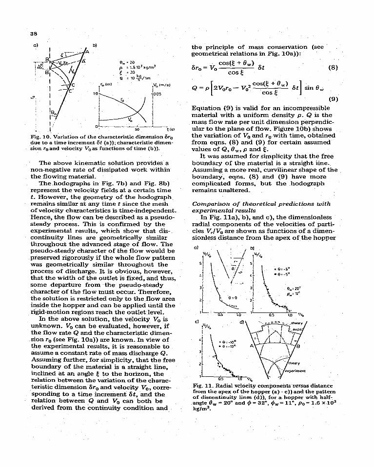
Fig. IO. Variation of the characteristic dimension 61-0 due to a time increment St (a)); characteristic dimen- sion re and velocity V, as functions of time (b)).
The above kinematic solution provides a non-negative rate of dissipated work within the flowing material_
The hodographs in Fig. ‘7b) and Fig. 8b) represent the velocity fields at a certain time t. However, the geometry of the hodograph remains similar at any time t since the mesh of velocity characteristics is time-independent. Hence, the flow can be described as a pseudo- steady process. This is confirmed by the experimental results, which show that dis- continuity lines are geometrically similar throughout the advanced stage of flow. The pseudo-steady character of the flow would be preserved rigorously if the whole ff ow pattern was geometrically similar throughout the process of discharge. It is obvious, however, that the width of the outlet is fixed, and thus, some departure from the pseudo-steady character of the flow must occur. Therefore, the solution is restricted only to the flow area inside the hopper and can be applied until the rigid-motion regions reach the outlet level.
In the above solution, the velocity V, is unknown. V, can be evaluated, however, if the flow rate Q and the characteristic dimen- sion r,-, (see Fig. 1Oa)) are known. In view of the experimental results, it is reasonable to assume a constant rate of mass discharge Q_ Assuming further, for simplicity, that the free boundary of the material is a straight line, inclined at an angle .$ to the horizon, the relation between the variation of the charac- teristic dimension 6r,-, and velocity V-,, corre- sponding to a time increment 6t, and the reIation between Q and V, can both be derived from the continuity condition and
the principle of mass conservation (see geometrical relations in Fig. lOa)):
(8) 6r, = v, cos(E + e,“) 6t
cos ,!j
Q = P 2Vc,r, - v,2 cosg + 6,)
6t cos g I
sin 8,
(9) Equation (9) is valid for an incompressible material with a uniform density p_ Q is the mass flow rate per unit dimension perpendic- ular to the plane of flow. Figure 19b) shows the variation of V, and r,, with time, obtained from eqns. (8) and (9) for certain assumed values of Q, Bu-, p and Sj.
It was assumed for simplicity that the free boundary of the material is a straight iine. Assuming a more real, curvilinear shape of the boundary, eqns. (8) and (9) have more complicated forms, but the hodograph remains unaltered-
Comparison of theoretical predictions with e2-perimental results
In Fig. lla), b), and c), the dimensionless radial components of the velocities of parti- cles WV,, are shown as functions of a dimen- sionless distance from the apex of the hopper
Cl
Fig. 11_ Radial velocity components uersus distance from the apex of the hopper (a) - c)) and the pattern of discontinuity lines (a)), for a hopper with half- angle 0, = kg/m3.
20” and Q = 32”, C& = ll”, po = 1.6 X lo3

0) b)
Fig. 12. Radial velocity components z.zrsus distance from the apex (a), b)) and the pattern of discon- tinuity lines (c)). for a hopper with half-angle 8, = 20” and Q = 32”. 9, = 25”, p. = 1.6 x 10” kglm3_
Fig_ 13_ Velocity vectors and discontinuity lines determined from experiments and theoretical predic- tions (8, = 15”, Q = 32”, 9, = 11’).
r/r,,_ The circles represent the experimentally obtained results, whereas the solid lines pertain to theoretical values. The experi- mental results in Fig. 11 refer to a hopper
39
with half-angle 6,,. = 20”, wall friction angle c& = 11” and initial density p. = l-6 X 10’ kg/m3. Theoretical results (solid line) were obtained under the assumption of incompres- sibility of the flow and for the angle Q = 32”, as measured in a triasial test_ The shape of the discontinuities in the velocity field and the velocity distribution along the arc AB are shown in Fig_ lid). The results for the same hopper, but with 9, = 23O, are shown in Fig. 12.
A comparison of the experimentally measured and theoretically predicted particle velocities and location of the velocity dis- continuity lines for a hopper model with half- angle 8, = 15” and wall friction angle 0, = 11” is shown in Fig. 13-
The results shown in Figs_ 11,12 and 13 indicate fairly good agreement between the theoretical solution and experimental observations-
CONCLUSIONS
The velocity field was esperimentally
determined in a wedge-shaped hopper model containing dry sand, and an attempt towards a theoretical description of the advanced stage of fiow was carried out.
Mass flo~v or plug fiow mechanisms are likely to appear in the initial stage of flow_ In both mechanisms, distinct narrow zones of large shear deformation (velocity discon- tinuities), accompanied by dilation of the material, are present. After the initial stage of flow is complet.ed, the entire material starts to move and the pattern of the velocity discontinuities becomes geometrically similar throughout the advanced stage of flow_ The flow rate appears to be constant in both initial and advanced stages of flow_
X theoretical description of the kinematics of the advanced flow, based upon the plane plastic flow theory of incompressible material, coupled with the radial stress field, seems to accurately describe the real velocity field, particularly in hoppers with smooth walls_ -4 pseudo-steady mechanism is suggested for the advanced stage of flow- A similar strategy of solving kinematics in hoppers was proposed earlier by Pariseau [I] _ However, in the latter paper, the directions of principal strain rates were determined esperimentally, and bound-

40
ary conditions for velocities differed from those proposed in this paper. The description proposed here gives results similar to those obtained by Drescher, Cousens and Bransby Ill], who assumed the presence of only one pair of discontinuity lines in the velocity field. This approximation seems to be reasonable since the jump in the velocity vectors across the other discontinuities is relatively small, as demonstrated in the present paper.
This paper was focused only on a small part of the problems associated with flo:v of granular cohesionless materials through hoppers. Although the existence of discon- tinuities in the velocity field was reported previously bf other authors, the observations of their development presented in this paper contribute to a better understanding of the kinematics of the flow process. Comparison of the mathematical description of the advanced flow presented in the paper with experimental results allows one to believe that the rigid-perfectly plastic model is a good approximation for granular material in advanced flow. The formulation of a velocity boundary value problem in the initial stage of flow remains a subject of research. It is believed that in this stage of flow only part of the material in the hopper experiences plastic deformation, and therefore traditional plastic flow theory does not seem to be a promising framework of analysis.
ACKNOWLEDGEh5ENTS
The Author would like to thank Professor A. Drescher for his helpful advice and for allowing the use of his X-radiographs in this paper. The Author is also grateful to the Council for International Exchange of Schol-
ars for financial support while doing research at the University of Minnesota.
REFERENCES
1 W. G. Pariseau, Powder Technoi., 3 (1970) 218. 2 P. Al. Blair-Fish and P. L. Bransby. J_ Engng. Ind..
Trans. ASME. Ser. B. 95 (1973) 17. 3 P. L. Bransby and P. M. Blair-Fish, Powder
Technoi_. I I (1975) 273_ 4 J. Lee, S. C. Cowin and J. S. Templeton. Trans.
Sot. RheoL. IS (1974) 245. 5 R. hI_ Nedderman and U_ Tikziin. Powder Tech-
nol.. 22 (1979) 243. 6 U. Tiiziin and R. hI_ Nedderman, Powder Tech-
nol. 31 (1982) 27. 7 R. T!. Shield, Q. =Ippl. Math., I I (1953) 61- 8 R. T. Shield, J_ .Wech. Phys. Solids, 3 (1955) 236. 9 A. IV. Jenike, Gravity FZow of Bulk Soiids, Bull.
Univ_ Utah 108. vol_ 52 (1961). 10 A. J. hI_ Spencer, J_ AIech_ Phys. Solids. I2 (1964)
337. 11 A. Drescher, T_ W. Cousens and P. L. Bransby,
Gtiotechnique. 28 (1978) 27. 12 J_ Litwiniszyn, Bull. Acad. Pal. Sci_. 11 (1963)
593. 13 W. 1%‘. hlullins, J. AppZ_ Phys. 43 (1972) 665_ 14 W. W. hlullins, Powder Techl;oZ_. 23 (1979) 115. 15 P_ L. Bransby. P. AI_ Blair-Fish and R. G. James,
Powder TechnoL. 8 (1973) 197. 16 J. 0. Cutress and R. F_ Pulfer, Powder Technol.. I
(1967) 213. 17 R. Butterfield, R. Harkness and K. Andrawes,
GPotechnique, 20 (1970) 308. 18 R. G. James, Report No. CUED/C-SoiZsfLNI
(1973). Engng. Dept. University of Cambridge_ 19 B. 0. Hardin and F. E. Richart, Jr., Proc_ ASCE.
89 (1963) Shil, 33 - 65. 20 E. Drescher and R. hlichalowski, Mech. Teoret-
Stos., I7 (1979) No. 3 (in Polish) 441. 21 D. M. Walker, Chem. Eng_ Sci_, 21 (1966) 975. 22 J. K. Walters, Chem. Eng. Sci_. 28 (1973) 779. 23 S. B. Savage and R. N. Yang. Znt. J. Mech. Sci_.
I2 (1970) 678 24 R_ hl. Horne and R. hf. Nedderman, Powder
TechnoL. 19 (1978) 243. 25 A. P_ Green. J_ Mech. Phys. Solids. 2 (1954) 73.