Embed Size (px)
Citation preview
Application Note
For this A/V Engineer,appearances are not
deceiving
Using a DMM to test A/V systemsFor Tom Grieshaber, of Seattle-based Vulcan, Inc., every newaudiovisual (A/V) system thecompany develops is virtually acustom project. Although eachuses many of the same compo-nents as its predecessors, therequirements of Vulcan’s cus-tomers virtually guarantee thatthe next system on the drawingboard will be a new adventure.
As manager of the systems-engineering group, Grieshaber isresponsible for designing andcommissioning all of these newA/V systems. Commissioning asystem invariably involves twodistinct processes:
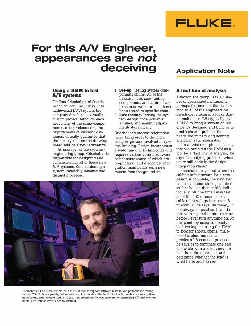
Grieshaber and his team custom-built this test rack to support software burn-in and performance testingfor over 20 LCD touch panels, before installing the panels in the field. The touch panels are also a custommanufacture, and together with a PC they run proprietary Vulcan software for controlling A/V and environ-mental applications (from video to lighting).
1. Set-up. Testing system com-ponents offline. All of theinfrastructure, core routingcomponents, and control sys-tems must work, or must havebeen tested to specifications.
2. Live testing. Testing the sys-tem design once power isapplied, and making adjust-ments dynamically.
Grieshaber’s process orientationhelps bring order to the morecomplex process involved in sys-tem building. Design incorporatesa wide range of technologies andrequires various control softwarecomponents (some of which areproprietary), and a separate inte-gration team builds each newsystem from the ground up.
A first line of analysisAlthough the group uses a num-ber of specialized instruments,perhaps the one tool that is com-mon to all of the engineers onGrieshaber’s team is a Fluke digi-tal multimeter. “We typically usea DMM to bring a system onlineonce it’s designed and built, or totroubleshoot a problem thatneeds preliminary engineeringanalysis,” says Grieshaber.
“In a twist on a phrase, I’d saythat we bring out the DMM as atool for a ‘first line of analysis,’ hesays, “identifying problems whenwe’re still early in the designintegration stage.”
Grieshaber says that when thecabling infrastructure for a newdesign is complete, the next stepis to isolate discrete logical blocksso that he can then certify indi-vidually. “At one time I may testall of the 100 or more coaxialcables that will go from room Ato room B,” he says. “In theory, ifnot always in practice, I can dothat with my entire infrastructurebefore I ever turn anything on. Atthis point, by using continuity orload testing, I’m using the DMMto look for shorts, opens, misla-beled cables, and similarproblems.” A common practice,he says, is to terminate one endof a cable with a load, view theload from the other end, anddetermine whether the load iswhat he expects to see.
2 Fluke Corporation For this A/V Engineer, appearances are not deceiving
“For a video cable, I can put a75 Ω terminator on one side. If Igo to the other end of the cableand check for DC resistance, I canget a ‘quick pass’ feel for theimpedance I will see on thecable. In short, I should find a DCresistance of about 75 Ω. If that’swhat appears, I can continuewith confidence. If not, there’s aproblem. Higher or lower resist-ance measurements couldindicate an open circuit, bad ter-mination, short, or other cablinganomaly.”
According to Grieshaber, theuse of a DMM simply reinforcesthe application of good commonsense. “When we build a systemand test the infrastructure, we’relooking for absolutely anythingthat could go wrong once weturn it on.”
Checking gain stagesOnce the various logical blocks in the system have been fullytested, it’s time to energize the system.
“Assume that the destination isa video display, and my source is a server that serves out high-definition video content. Toperform measurements on thatsignal chain, I would use a signalgenerator to provide a specifictest signal. I need a good refer-ence signal — something that has fixed amplitude at fixed frequency ranges.”
In the process of commis-sioning a system, Grieshaber performs a series of gain adjust-ments. This process involves asignal that goes through multipledevices, each with an adjustableamplifier. “I’ll be looking at theoutputs of these amplifiers at sev-eral places in the circuit — alsocalled gain stages — and I canuse the DMM to measure voltageat each stage. Using this process,I work my way, one stage at atime, from source to destination,adjusting the output voltage ateach stage to control the voltagegain or loss that I want to see ateach amplifier.”
If Grieshaber finds variabilityin the outputs of the amplifiers,he can ‘push’ the gain up ordown to compensate for factorssuch as cabling loss or connectorloss. “I need to optimize howthose gain stages interact witheach other, in order to reduce theoverall noise floor and provide astable signal.”
An army of oneThe DMM is an “incredibly multi-faceted tool,” says Grieshaber.“It’s like a Swiss Army knife. Withit I can confirm or deny prelimi-nary assumptions, suspicions ortheories about what’s going on.And then, only if I need to, I canresort to more specialized, appli-cation-specific instruments.
“If I want to put the systemthrough its paces, I’ll specify avoltage — let’s say for the colorblack — because I’m using blackas a reference point. Black, fromthe perspective of a signal gener-ator, has a specific voltage andamplitude at fixed frequencies. I’ll
+/– +/–
+/–
Signalgenerator
+/–Video server
Sources Destinations
Room BMain Equipment Room A
Connect75
terminator
Measure DCrestance ofloaded cable
Measure DCresistance ofloaded cable
Connect75
terminator
Setvoltage
Measurevoltage
Output
Input
Measurevoltage
DistributorAmplifier
256X
256
Patch Router Patch Patch
VTR
Videodisplay
+/–+/–
+/–
+/–
+/–
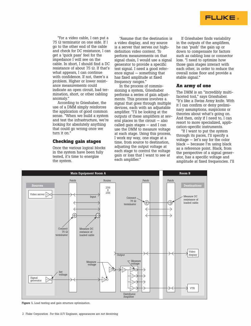
Figure 1. Load testing and gain structure optimization.
3 Fluke Corporation For this A/V Engineer, appearances are not deceiving
Power considerationsWhile system testing is key toperformance, Grieshaber is just asfocused on requirements for cleanpower. “With the high-levelpower infrastructure, we are con-cerned that, if the provided poweris either at the wrong voltage orexhibits strong harmonics, we’llsee the consequences ripplethroughout the system.”
For that reason, he conductstwo types of power-supply test-ing for every system:• Testing of the high-voltage
power infrastructure
• Testing of system power sup-plies and how they respond tothe delivered power
“Often we specify an isolatedground system for power to theA/V and IT systems, and thatmeans testing for isolationbetween two isolated ground systems. The DMM makes it veryeasy to get a quick read on howwell an isolated ground has beenimplemented. One way to do thatis to test for continuity betweenthe two systems.” (See Figure 2,Test 1.)
check various points along thepath and ask ‘have I incurred avoltage loss, or a voltage gain?’
“I’ll take my DMM out andstick it on various nodes to lookat voltages and currents; typi-cally, with analog audio or videosignals, I’m looking at voltage. At the input and output of a particular stage, I should find thevoltage within a narrow range, asspecified by the test signal I amusing. If I find what I expect withthe DMM, I can say, for the mostpart, that things are workingproperly.”
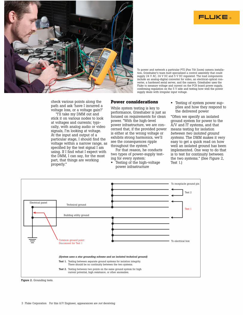
To power and network a particular PTZ (Pan Tilt Zoom) camera installa-tion, Grieshaber’s team built specialized a control assembly that couldsupply 24 V AC, 24 V DC and 5 V DC regulated. The load componentsinclude an analog-digital converter for video, an electrical-optical con-verter, a hardened serial server, and the camera. Grieshaber uses theFluke to measure voltage and current on the PCB board power supply,confirming regulation on the 5 V side and testing how well the powersupply deals with irregular input voltage.
Electrical panelTechnical ground
Building utility ground
Common ground point:Disconnect for Test 1
To receptacle ground pin
To electrical box
Test 2
Test 1
(System uses a star grounding scheme and an isolated technical ground)
Test 1. Testing between separate ground systems for isolation integrity. There should be no continuity between the two systems.
Test 2. Testing between two points on the same ground system for high current potential, high resistance, or other anomalies.
Figure 2. Grounding tests.
4 Fluke Corporation For this A/V Engineer, appearances are not deceiving
“Another critical test with theDMM is to look for current leak-age and/or current potentialbetween different ground pointsin the same system.” (See Figure2, Test 2.) Grieshaber will typi-cally test a ground point from oneside of the room to the other, atest that can reveal a good dealof information about the powersystem. “If I have an unusuallyhigh current potential betweentwo ground points, I know that Imay have a problem. I may needto take corrective action to fix theproblem. Or, if that’s not anoption, I’ll take some action inthe A/V system to compensate forit. Audio comes to mind. It’s veryeasy to get audible noise, and alot of times that noise relatesdirectly to the grounding schemeand power system in use.”
Fluke CorporationPO Box 9090, Everett, WA USA 98206
Fluke Europe B.V.PO Box 1186, 5602 BD Eindhoven, The Netherlands
For more information call:In the U.S.A. (800) 443-5853 or Fax (425) 446-5116In Europe/M-East/Africa (31 40) 2 675 200 or Fax (31 40) 2 675 222In Canada (800) 36-FLUKE or Fax (905) 890-6866From other countries +1 (425) 446-5500 or Fax +1 (425) 446-5116Web access: http://www.fluke.com
©2005 Fluke Corporation. All rights reserved.Printed in U.S.A. 4/2005 2446724 PubID 10938-eng
Fluke.Keeping your worldup and running.
Back to basicsIn Grieshaber’s approach to testing complex A/V systems,simplicity and common sense are recurring themes.
“Audio and video engineerstend to want to use the mostspecialized piece of test equip-ment for troubleshooting. But,from my experience as an integrator, I’ve learned there area lot of things you can do, andshould do, with a DMM. Theseare first-line-of-analysis tests thatdon’t require hauling around abig piece of test equipment. If Ican use the DMM as a ‘discoverytool,’ I can go back later and pullout more specialized equipment ifrequired.”
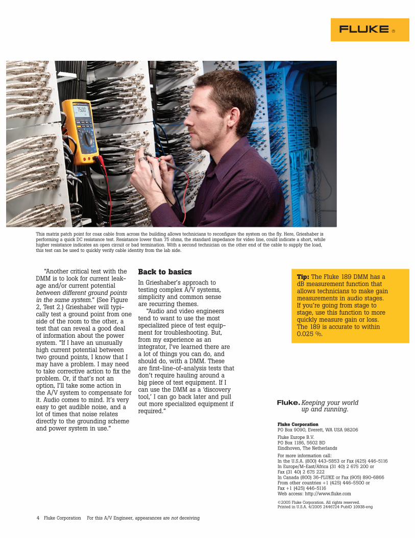
This matrix patch point for coax cable from across the building allows technicians to reconfigure the system on the fly. Here, Grieshaber isperforming a quick DC resistance test. Resistance lower than 75 ohms, the standard impedance for video line, could indicate a short, whilehigher resistance indicates an open circuit or bad termination. With a second technician on the other end of the cable to supply the load,this test can be used to quickly verify cable identity from the lab side.
Tip: The Fluke 189 DMM has a dB measurement function that allows technicians to make gainmeasurements in audio stages. If you’re going from stage to stage, use this function to morequickly measure gain or loss. The 189 is accurate to within 0.025 %.