Embed Size (px)
Citation preview
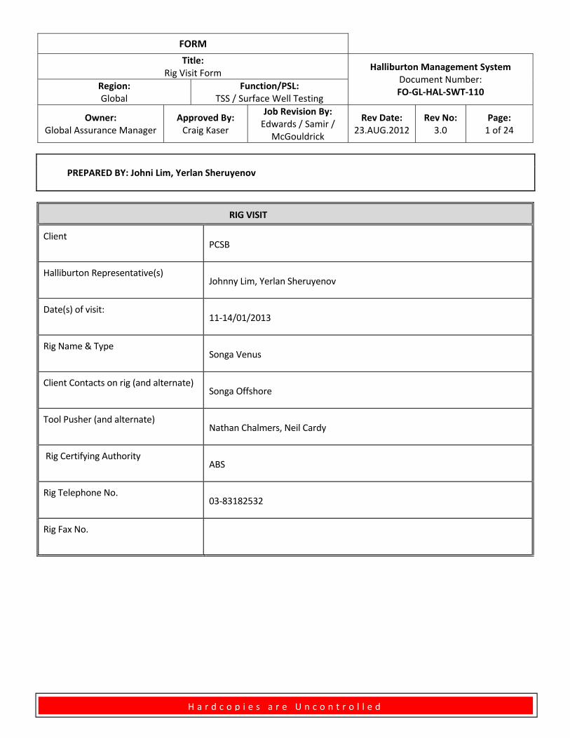
FORM
Title: Rig Visit Form
Halliburton Management System Document Number: FO‐GL‐HAL‐SWT‐110
Region: Global
Function/PSL: TSS / Surface Well Testing
Owner: Global Assurance Manager
Approved By: Craig Kaser
Job Revision By: Edwards / Samir /
McGouldrick
Rev Date: 23.AUG.2012
Rev No: 3.0
Page: 1 of 24
H a r d c o p i e s a r e U n c o n t r o l l e d
PREPARED BY: Johni Lim, Yerlan Sheruyenov
RIG VISIT
Client
PCSB
Halliburton Representative(s)
Johnny Lim, Yerlan Sheruyenov
Date(s) of visit:
11‐14/01/2013
Rig Name & Type
Songa Venus
Client Contacts on rig (and alternate)
Songa Offshore
Tool Pusher (and alternate)
Nathan Chalmers, Neil Cardy
Rig Certifying Authority
ABS
Rig Telephone No.
03‐83182532
Rig Fax No.
FORM
Title: Rig Visit Form
Halliburton Management System Document Number: FO‐GL‐HAL‐SWT‐110
Region: Global
Function/PSL: TSS / Surface Well Testing
Owner: Global Assurance Manager
Approved By: Craig Kaser
Job Revision By: Edwards / Samir /
McGouldrick
Rev Date: 23.AUG.2012
Rev No: 3.0
Page: 2 of 24
H a r d c o p i e s a r e U n c o n t r o l l e d
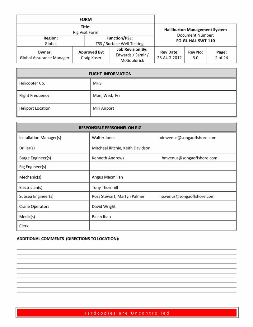
FLIGHT INFORMATION
Helicopter Co. MHS
Flight Frequency Mon, Wed, Fri
Heliport Location Miri Airport
RESPONSIBLE PERSONNEL ON RIG
Installation Manager(s) Walter Jones [email protected]
Driller(s) Mitcheal Ritchie, Keith Davidson
Barge Engineer(s) Kenneth Andrews [email protected]
Rig Engineer(s)
Mechanic(s) Angus Macmillan
Electrician(s) Tony Thornhill
Subsea Engineer(s) Ross Stewart, Martyn Palmer [email protected]
Crane Operators David Wright
Medic(s) Balan Ibau
Clerk
ADDITIONAL COMMENTS (DIRECTIONS TO LOCATION):
FORM
Title: Rig Visit Form
Halliburton Management System Document Number: FO‐GL‐HAL‐SWT‐110
Region: Global
Function/PSL: TSS / Surface Well Testing
Owner: Global Assurance Manager
Approved By: Craig Kaser
Job Revision By: Edwards / Samir /
McGouldrick
Rev Date: 23.AUG.2012
Rev No: 3.0
Page: 3 of 24
H a r d c o p i e s a r e U n c o n t r o l l e d
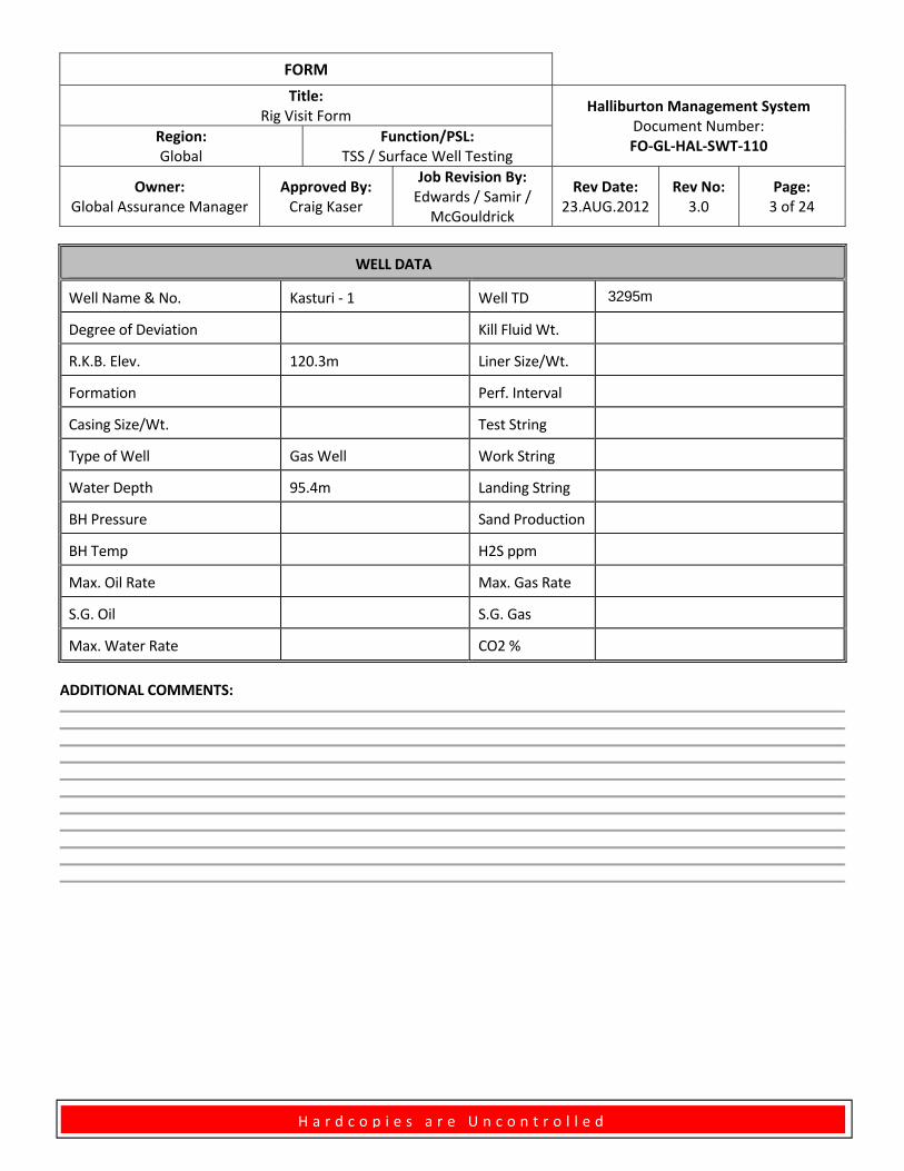
WELL DATA
Well Name & No. Kasturi ‐ 1 Well TD 3295m
Degree of Deviation Kill Fluid Wt.
R.K.B. Elev. 120.3m Liner Size/Wt.
Formation Perf. Interval
Casing Size/Wt. Test String
Type of Well Gas Well Work String
Water Depth 95.4m Landing String
BH Pressure Sand Production
BH Temp H2S ppm
Max. Oil Rate Max. Gas Rate
S.G. Oil S.G. Gas
Max. Water Rate CO2 %
ADDITIONAL COMMENTS:
FORM
Title: Rig Visit Form
Halliburton Management System Document Number: FO‐GL‐HAL‐SWT‐110
Region: Global
Function/PSL: TSS / Surface Well Testing
Owner: Global Assurance Manager
Approved By: Craig Kaser
Job Revision By: Edwards / Samir /
McGouldrick
Rev Date: 23.AUG.2012
Rev No: 3.0
Page: 4 of 24
H a r d c o p i e s a r e U n c o n t r o l l e d
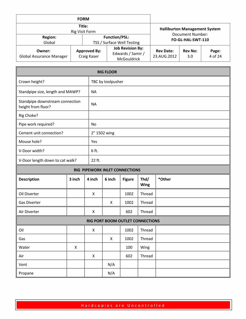
RIG FLOOR
Crown height? TBC by toolpusher
Standpipe size, length and MAWP? NA
Standpipe downstream connection height from floor?
NA
Rig Choke?
Pipe work required? No
Cement unit connection? 2” 1502 wing
Mouse hole? Yes
V‐Door width? 6 ft.
V‐Door length down to cat walk? 22 ft.
RIG PIPEWORK INLET CONNECTIONS
Description 3 inch 4 inch 6 inch Figure Thd/ Wing
*Other
Oil Diverter X 1002 Thread
Gas Diverter X 1002 Thread
Air Diverter X 602 Thread
RIG PORT BOOM OUTLET CONNECTIONS
Oil X 1002 Thread
Gas X 1002 Thread
Water X 100 Wing
Air X 602 Thread
Vent N/A
Propane N/A
FORM
Title: Rig Visit Form
Halliburton Management System Document Number: FO‐GL‐HAL‐SWT‐110
Region: Global
Function/PSL: TSS / Surface Well Testing
Owner: Global Assurance Manager
Approved By: Craig Kaser
Job Revision By: Edwards / Samir /
McGouldrick
Rev Date: 23.AUG.2012
Rev No: 3.0
Page: 5 of 24
H a r d c o p i e s a r e U n c o n t r o l l e d
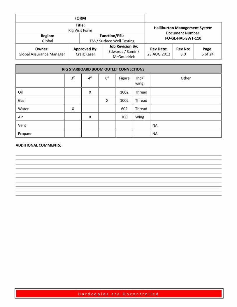
RIG STARBOARD BOOM OUTLET CONNECTIONS
3” 4” 6” Figure Thd/ wing
Other
Oil X 1002 Thread
Gas X 1002 Thread
Water X 602 Thread
Air X 100 Wing
Vent NA
Propane NA
ADDITIONAL COMMENTS:
FORM
Title: Rig Visit Form
Halliburton Management System Document Number: FO‐GL‐HAL‐SWT‐110
Region: Global
Function/PSL: TSS / Surface Well Testing
Owner: Global Assurance Manager
Approved By: Craig Kaser
Job Revision By: Edwards / Samir /
McGouldrick
Rev Date: 23.AUG.2012
Rev No: 3.0
Page: 6 of 24
H a r d c o p i e s a r e U n c o n t r o l l e d
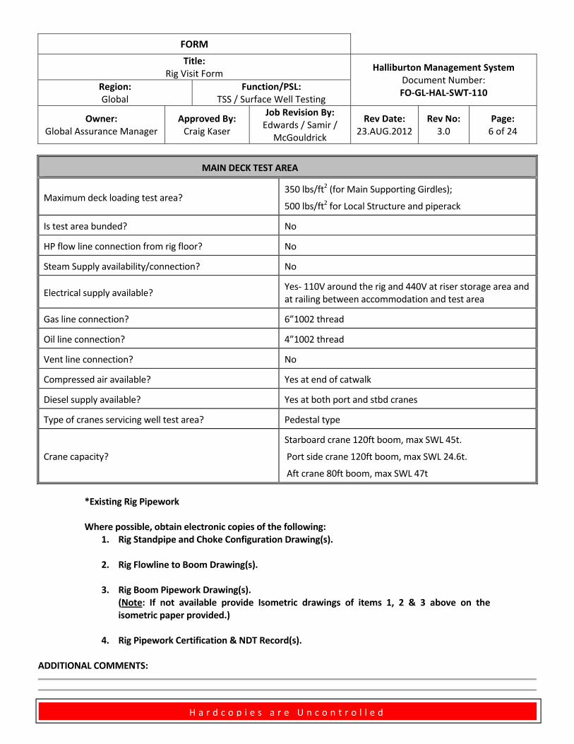
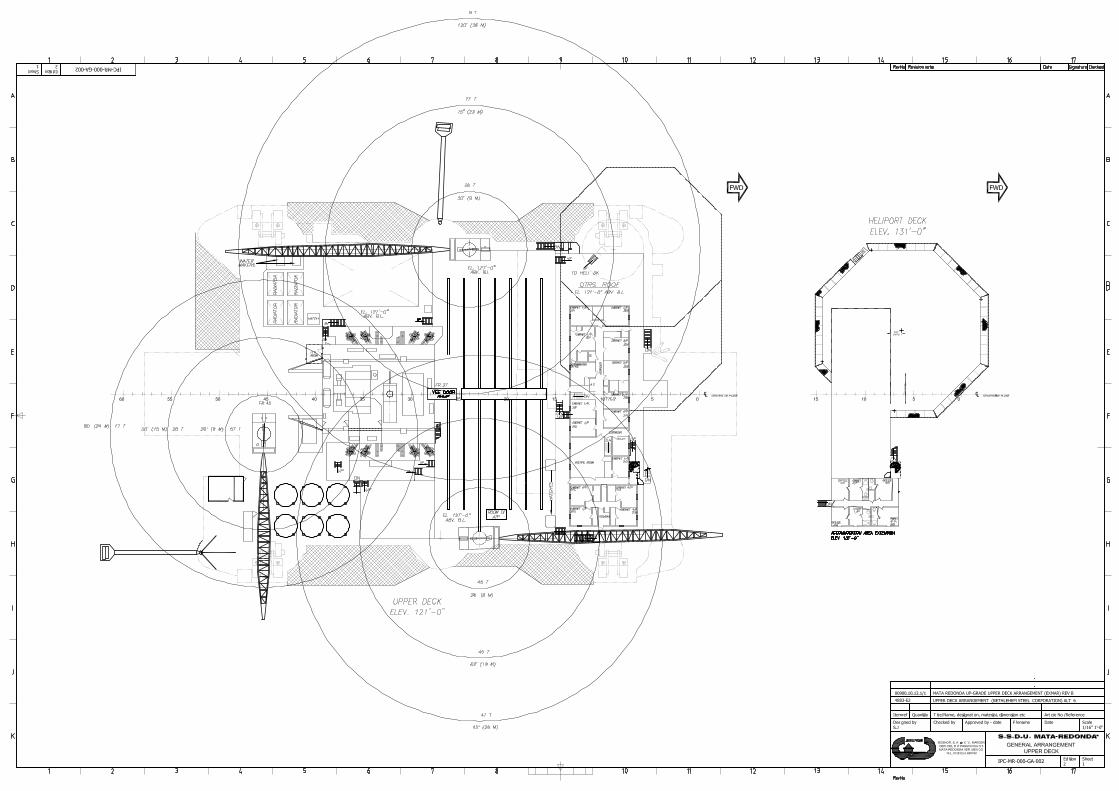
MAIN DECK TEST AREA
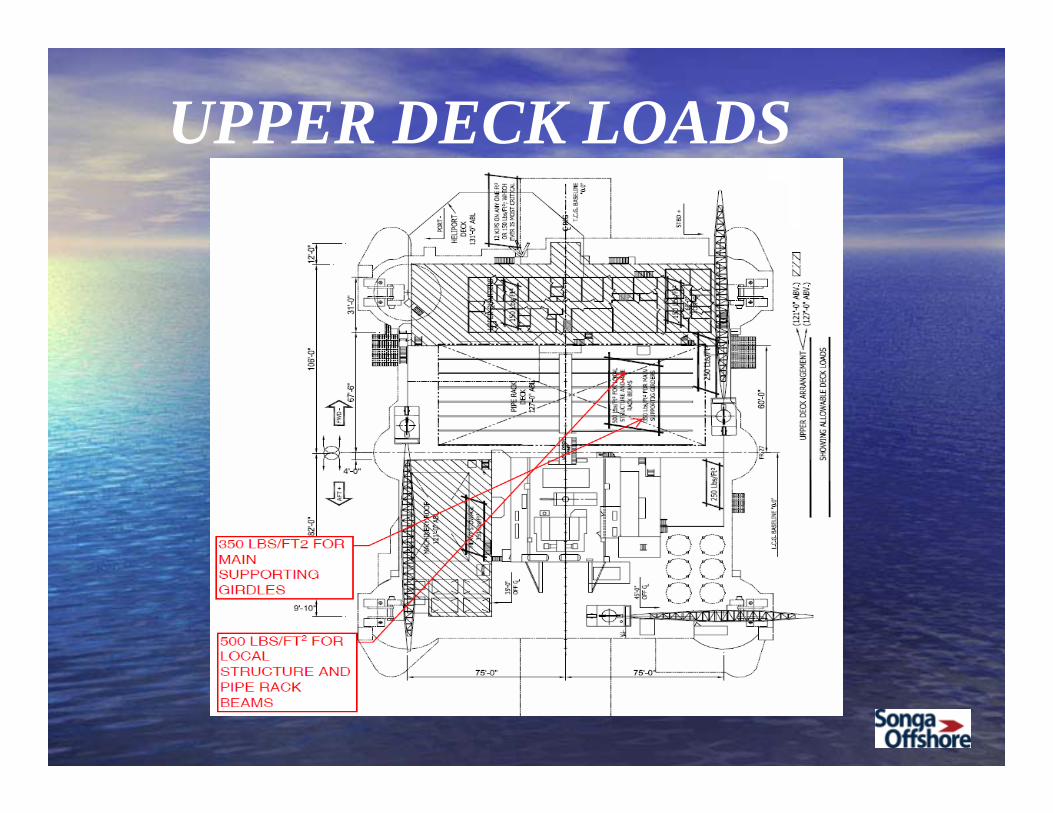
Maximum deck loading test area? 350 lbs/ft2 (for Main Supporting Girdles);
500 lbs/ft2 for Local Structure and piperack
Is test area bunded? No
HP flow line connection from rig floor? No
Steam Supply availability/connection? No
Electrical supply available? Yes‐ 110V around the rig and 440V at riser storage area and at railing between accommodation and test area
Gas line connection? 6”1002 thread
Oil line connection? 4”1002 thread
Vent line connection? No
Compressed air available? Yes at end of catwalk
Diesel supply available? Yes at both port and stbd cranes
Type of cranes servicing well test area? Pedestal type
Crane capacity?
Starboard crane 120ft boom, max SWL 45t.
Port side crane 120ft boom, max SWL 24.6t.
Aft crane 80ft boom, max SWL 47t
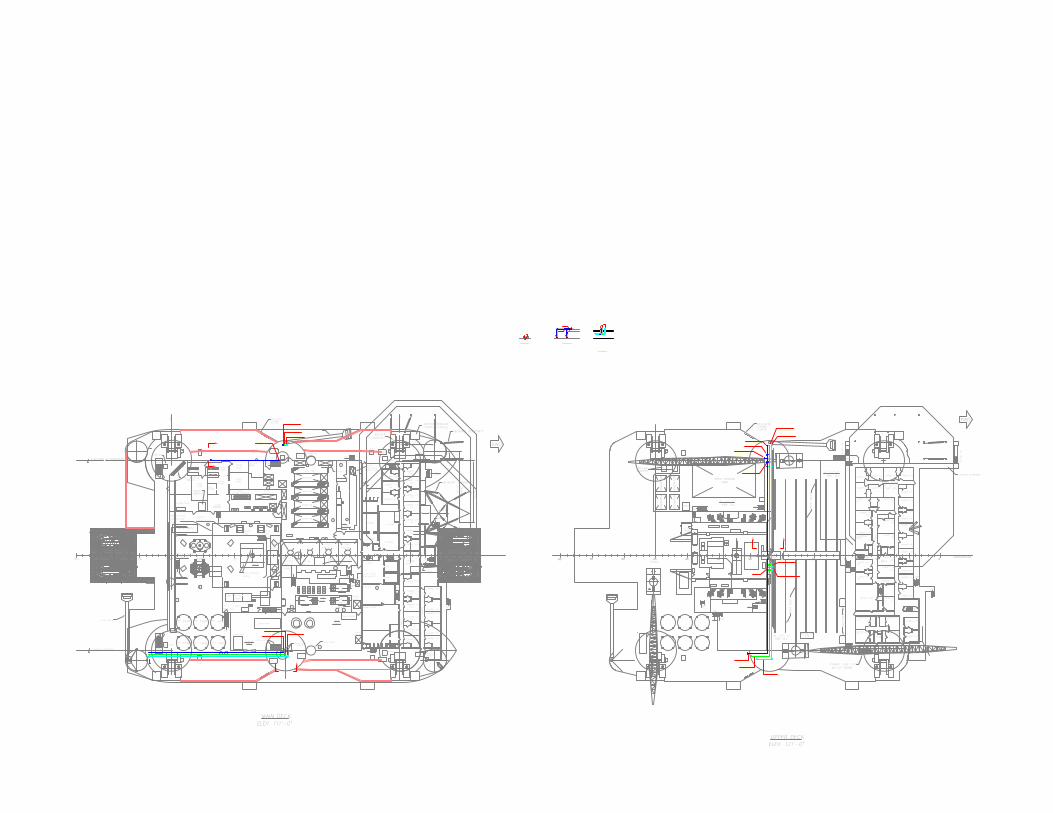
*Existing Rig Pipework Where possible, obtain electronic copies of the following:
1. Rig Standpipe and Choke Configuration Drawing(s).
2. Rig Flowline to Boom Drawing(s).
3. Rig Boom Pipework Drawing(s). (Note: If not available provide Isometric drawings of items 1, 2 & 3 above on the
isometric paper provided.)
4. Rig Pipework Certification & NDT Record(s).
ADDITIONAL COMMENTS:
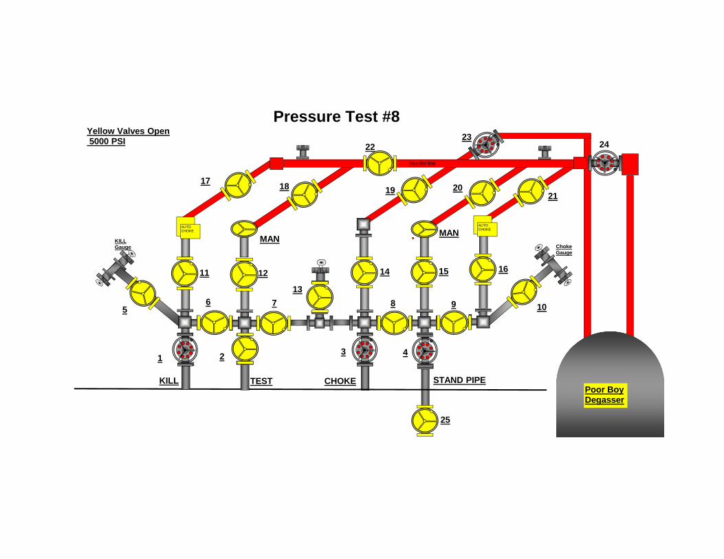
Pressure Test #8
213 4
56 7
2223
8 910
11 12
13
14 15
MAN
16
18 19 20
25
24
21
KILL TEST STAND PIPECHOKE
10
AUTOCHOKE
AUTOCHOKE
MAN
17
KILL Gauge Choke
Gauge
Poor BoyDegasser
Header line
Yellow Valves Open5000 PSI
ROOMAREA
HYD. OPERATED
CAISSON & PONTOONC
"P" TANKHATCH
VENT
V.L.
"P" TANK
DN
AREA
MHMH
"P" TANK
UP
CEMENT
FLARE BOOM
MUD PROCESS
"P" TANK"P" TANK
MH
"P" TANK
EL. 12'-2" ABV. MAIN DECK
TANKS
DNDOORS
SACK
HATCHABOVE
VENT
EXHAUST FANS(ABOVE)
HATCH
DN
VENT
BOOBY HATCH
MH
STOWAGE
CRANE PEDESTAL
VENTV.L.
HATCH VENT
HATCHABOVE
CEMENT UNIT
UPMH COAMING
PUMPROOM
MHMH
PUMPMUD
MUD PIT CHEMICAL
DN
MUD PIT
ROOM
(N) MUDPUMP
MH
UP
MH
UP FAN (ABOVE)55"Ø SUPPLY
HATCH
MOON POOL
BOOBY
YELLOW
90"BELOWCELLAR DECK
BOP
REEL
DERRICKFOOTING (TYP)
SUBSTRUCTUREDERRICK FLOOR
APV RACK
ABOVE
LATHE ROOM
MH
UP
MH
STOREROOM
CAISSON & PONTOONC
STORE
RACK
ABOVEHATCH
STORETOOLS
DN CO2 BOTTLE
STORE
STORE
ACCUM. BOTTLES
STORE
ROOM
DRY
B.O.P.
ROOM
ROOM
STORE
STOREROOM
VENT
V.L.
LC
HELIPORT SUPPORTS
BLUE
ACTIVEFR.27
ROOM
ACTIVE
SUBSEA
DN
REEL
MUD PITMUD PIT
SLUGGING PIT
ACTIVE RESERVE
ENGINE #3
ENGINE #4
MH
MH
ENG.CONTROLROOM
MH
CONTROLFR.9
BRIDGE
MHDN
F.O. TK.
ENGINE #1
ENGINE #2
MHB.O.P.
CONTROLS
HATCH
VENT
VENT
CRANEPEDESTAL
SERVICE PUMP
VENTV.L.
HATCH
VENT
LCB
HD
LW
R Q
TRS
BH
D U
PP
ER
QTR
S
TUGGERAIR
MH
FLARE BOOM
CABINET 2/P.
CABINET 2/P.
CABINET 2/P.
CABINET 2/P.
CABINET 2/P.
SMOKINGROOM
COR
RIDO
R
112
114
HOSPITAL
110
108
COR
RIDO
R
TV. ROOMLAUNDRY
A.C.
106
104
102
CABINET 2/P.
103
CABINET 2/P.
EMERG. GEN.
SUPPLYFAN (ABV.)
101
DN
LAUNDRY
CABINET 2/P.
CABINET 2/P.
CABINET 2/P.
CABINET 2/P.
CABINET 2/P.
CABINET 2/P.
CABINET 2/P.
CABINET 2/P.
P.F.C.ROOM
HELIPORT SUPPORTS
COMPRESSOR
STORE
DN
UP
COR
RIDO
R
DINNER ROOM
UP
KITCHEN MH A.C.
REF.
FRZ.
UP DN
126
122
124
120
116
118
CABINET 2/P.
CABINET 2/P.
CABINET 2/P.
CABINET 2/P.
CABINET 2/P.
CABINET 2/P.
UP
UP
27'-6"7'-6"
202530354045505560 051015
RELOCATEDLOADINGSTATION
WINCH
HATCH
ANCHOR WINDLASS CONTROL CONSOLE
ANCHORWINDLASS
FWD
ELECTRIC ROOM
DE
TOOLS ROOM
8'-4 7/8"
MAIN DECKELEV. 111'-0"
[185
93]
61'-0"
[147
83]
48'-6"
Ø4" AIR LINE
FR.45
RADIATO
R
MAKERSWATER
RADIATO
R
PIPE
RACK
ABV. B.L.EL. 127'-0"
W/110' BOOMCRANE CAB (TYP)
UP
UP
DN
DN
DN
UP
PIPE
RACK
FR.27
RAMPVEE DOOR
DN
DN
HATC
HES
DN
HATCH
RADIATO
R
DN
DN
RADIATO
R
EL. 121'-0"ABV. B.L.
RISER STOWAGEAREA
UP
EL. 127'-0"ABV. B.L.
UP
EL. 121'-0"
TO H
ELI. DK.
QTRS. ROOF
ROOM OFATP
UP
UP
CABINET 4/P.215
213 214
216LOCKERS
CABINET 4/P. CABINET 4/P.
CABINET 4/P.
212MEETING ROOM
CABINET 4/P.
210
208
A.C.
SUPERINTENDENT 206
204CABINET 4/P.
CABINET 2/P.
CABINET 2/P.
CABINET 4/P.
CABINET 4/P.
OFFICE
207
TOILETDN
DN
COR
RIDO
R
CORRIDOR
UP
I.T.P. ROOM
FWD
UPPER DECKELEV. 121'-0"
CABINET 4/P.209
50 45 40 3035 25 1520 10 5 0CENTERLINE PLANE
5560
203CABINET 2/P.
202201CABINET 2/P. CABINET 2/P.
CABINET 2/P.
UP
CABINET 2/P.
CABINET 2/P.
CABINET 2/P.
CABINET 2/P.
CABINET 2/P.
CABINET 2/P.
CABINET 2/P.
CABINET 2/P.
CABINET 2/P.
CABINET 2/P.
CABINET 2/P.
CABINET 2/P.
CABINET 2/P.
CABINET 2/P.CABINET 2/P.
CABINET 2/P.
CABINET 2/P.
FR.9
ABV. B.L.
UP
DN
TO H
ELI. DK.
UP
CATWALK PLATFORM
RELOCATEDLOADINGSTATION
4" OIL LINE
6" GAS LINE
4" AIR LINE
MAIN DECK
UPPER DECK
TO PIPE RACK DK
Ø4" OIL LINETO PIPE RACK DK
Ø6" GAS LINETO PIPE RACK DKA
PIPE RACK
Ø4" AIR LINE
SECTION A-ASECTION B-B
Ø4" AIR
LINE
(SC
H 40
)Ø4
" OIL LINE
(SC
H XX
S)Ø6
" GA
S LINE
(SC
H XX
S)
Ø4" AIR LINEFROM MAIN DECK
Ø4" OIL LINEFROM MAIN DECK
Ø6" GAS LINEFROM MAIN DECK
Ø4" AIR LINETO MAIN DECK
Ø4" OIL LINETO MAIN DECK
Ø6" GAS LINETO MAIN DECK
B
C
MAIN DECK
UPPER DECK
PIPE RACK
4" AIR LINE4" OIL LINE
6" GAS LINE
Ø6" GAS LINEFM PIPE RACK DK
Ø4" OIL LINEFROM PIPE RACK DK
Ø4" AIR LINEFROM PIPE RACK DK
6" GAS LINE
Ø4" AIR LINEØ4" OIL LINEØ6" GAS LINE
SECTION C-C
4" GATE VALVE
Ø4" AIR LINE (SCH 40)
PIPE RACK
6"x6" EQ. TEE(WITH FEMALE UNION)
4" GATE VALVE
MALE UNION(TYP)
GATE VALE (TYP)(YARD SUPPLY)
ؽ" FEMALE UNION
4"x4"EQ. TEE
12" DIVERTER LINE
B
Ø4" AIR LINEFROM MAIN DECKØ4" GATE VALVE
Ø4" GATE VALVE
(PORT/AFT)
ؽ" MALE UNION
C
A
Ø4" AIR LINETO PIPE RACK DK
FORM
Title: Rig Visit Form
Halliburton Management System Document Number: FO‐GL‐HAL‐SWT‐110
Region: Global
Function/PSL: TSS / Surface Well Testing
Owner: Global Assurance Manager
Approved By: Craig Kaser
Job Revision By: Edwards / Samir /
McGouldrick
Rev Date: 23.AUG.2012
Rev No: 3.0
Page: 7 of 24
H a r d c o p i e s a r e U n c o n t r o l l e d
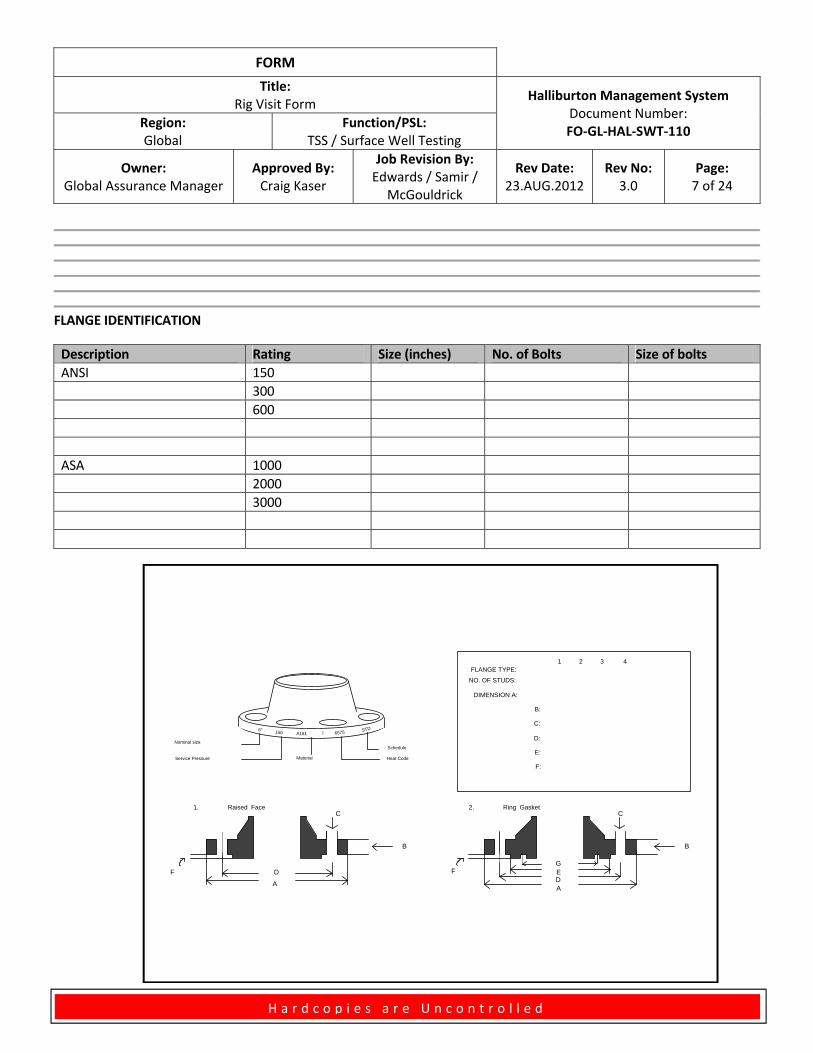
FLANGE IDENTIFICATION
Description Rating Size (inches) No. of Bolts Size of bolts
ANSI 150
300
600
ASA 1000
2000
3000
6" 150 A181 I 6575 STD
Nominal size
Service Pressure Material Heat Code
Schedule
A
B
C
DEFG
A
D
B
C
F
Raised Face Ring Gasket
FLANGE TYPE:
NO. OF STUDS:
DIMENSION A:
B:
C:
D:
E:
F:
1 2 3 4
1. 2.
FORM
Title: Rig Visit Form
Halliburton Management System Document Number: FO‐GL‐HAL‐SWT‐110
Region: Global
Function/PSL: TSS / Surface Well Testing
Owner: Global Assurance Manager
Approved By: Craig Kaser
Job Revision By: Edwards / Samir /
McGouldrick
Rev Date: 23.AUG.2012
Rev No: 3.0
Page: 8 of 24
H a r d c o p i e s a r e U n c o n t r o l l e d
ADDITIONAL COMMENTS:
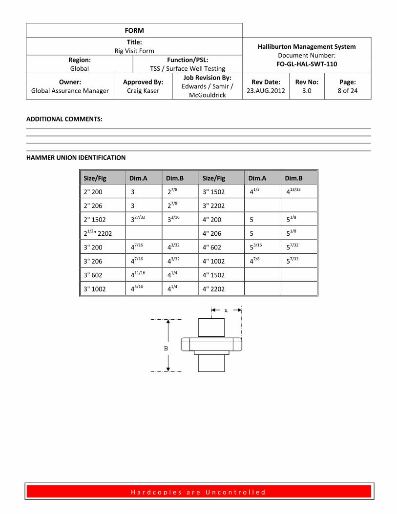
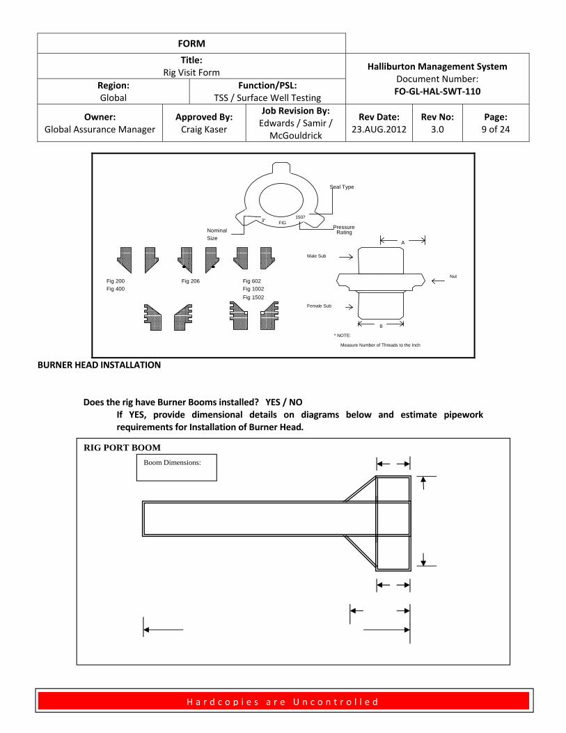
HAMMER UNION IDENTIFICATION
Size/Fig Dim.A Dim.B Size/Fig Dim.A Dim.B
2" 200 3 27/8 3" 1502 41/2 413/32
2" 206 3 27/8 3" 2202
2" 1502 327/32 33/16 4" 200 5 51/8
21/2" 2202 4" 206 5 51/8
3" 200 47/16 43/32 4" 602 53/16 57/32
3" 206 47/16 43/32 4" 1002 47/8 57/32
3" 602 411/16 41/4 4" 1502
3" 1002 45/16 41/4 4" 2202
FORM
Title: Rig Visit Form
Halliburton Management System Document Number: FO‐GL‐HAL‐SWT‐110
Region: Global
Function/PSL: TSS / Surface Well Testing
Owner: Global Assurance Manager
Approved By: Craig Kaser
Job Revision By: Edwards / Samir /
McGouldrick
Rev Date: 23.AUG.2012
Rev No: 3.0
Page: 9 of 24
H a r d c o p i e s a r e U n c o n t r o l l e d
A
B
Male Sub
Female Sub
Nut
* NOTE:
Measure Number of Threads to the Inch
3" FIG1502
Nominal
Size
Seal Type
PressureRating
Fig 200
Fig 400
Fig 206 Fig 602
Fig 1002
Fig 1502
BURNER HEAD INSTALLATION
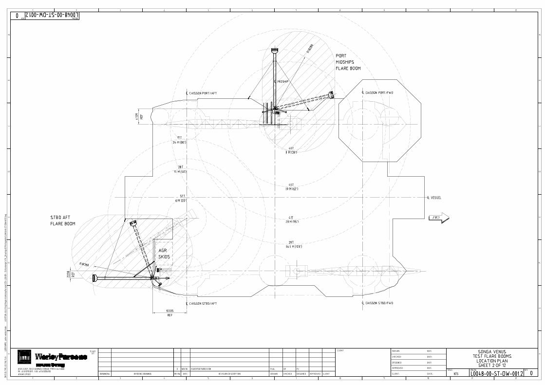
Does the rig have Burner Booms installed? YES / NO If YES, provide dimensional details on diagrams below and estimate pipework
requirements for Installation of Burner Head.
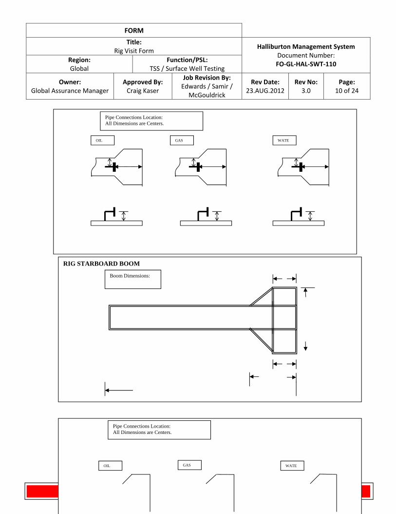
RIG PORT BOOM
Boom Dimensions:
FORM
Title: Rig Visit Form
Halliburton Management System Document Number: FO‐GL‐HAL‐SWT‐110
Region: Global
Function/PSL: TSS / Surface Well Testing
Owner: Global Assurance Manager
Approved By: Craig Kaser
Job Revision By: Edwards / Samir /
McGouldrick
Rev Date: 23.AUG.2012
Rev No: 3.0
Page: 10 of 24
H a r d c o p i e s a r e U n c o n t r o l l e d
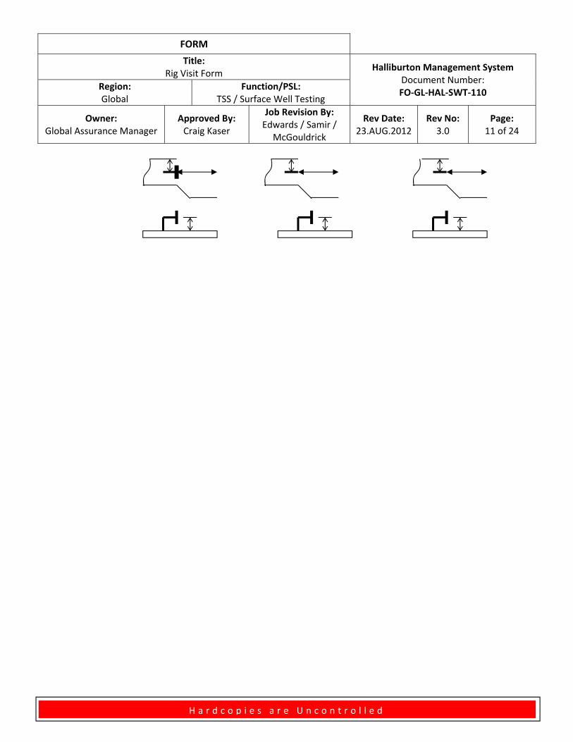
Pipe Connections Location: All Dimensions are Centers.
OIL GAS WATE
RIG STARBOARD BOOM
Boom Dimensions:
Pipe Connections Location: All Dimensions are Centers.
OIL GAS WATE
FORM
Title: Rig Visit Form
Halliburton Management System Document Number: FO‐GL‐HAL‐SWT‐110
Region: Global
Function/PSL: TSS / Surface Well Testing
Owner: Global Assurance Manager
Approved By: Craig Kaser
Job Revision By: Edwards / Samir /
McGouldrick
Rev Date: 23.AUG.2012
Rev No: 3.0
Page: 11 of 24
H a r d c o p i e s a r e U n c o n t r o l l e d
FORM
Title: Rig Visit Form
Halliburton Management System Document Number: FO‐GL‐HAL‐SWT‐110
Region: Global
Function/PSL: TSS / Surface Well Testing
Owner: Global Assurance Manager
Approved By: Craig Kaser
Job Revision By: Edwards / Samir /
McGouldrick
Rev Date: 23.AUG.2012
Rev No: 3.0
Page: 12 of 24
H a r d c o p i e s a r e U n c o n t r o l l e d
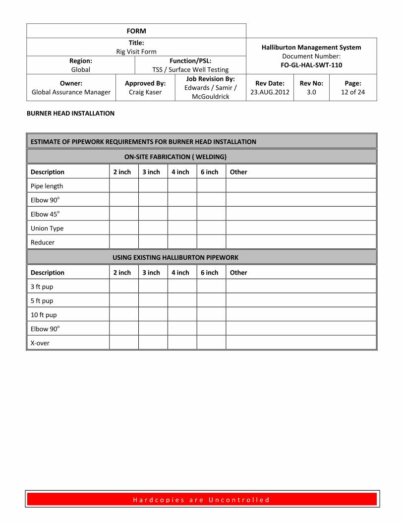
BURNER HEAD INSTALLATION
ESTIMATE OF PIPEWORK REQUIREMENTS FOR BURNER HEAD INSTALLATION
ON‐SITE FABRICATION ( WELDING)
Description 2 inch 3 inch 4 inch 6 inch Other
Pipe length
Elbow 90o
Elbow 45o
Union Type
Reducer
USING EXISTING HALLIBURTON PIPEWORK
Description 2 inch 3 inch 4 inch 6 inch Other
3 ft pup
5 ft pup
10 ft pup
Elbow 90o
X‐over
FORM
Title: Rig Visit Form
Halliburton Management System Document Number: FO‐GL‐HAL‐SWT‐110
Region: Global
Function/PSL: TSS / Surface Well Testing
Owner: Global Assurance Manager
Approved By: Craig Kaser
Job Revision By: Edwards / Samir /
McGouldrick
Rev Date: 23.AUG.2012
Rev No: 3.0
Page: 13 of 24
H a r d c o p i e s a r e U n c o n t r o l l e d
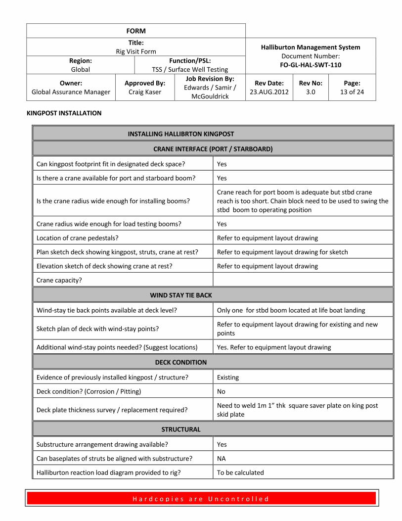
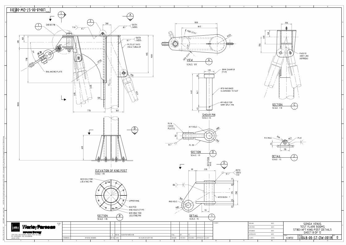
KINGPOST INSTALLATION
INSTALLING HALLIBRTON KINGPOST
CRANE INTERFACE (PORT / STARBOARD)
Can kingpost footprint fit in designated deck space? Yes
Is there a crane available for port and starboard boom? Yes
Is the crane radius wide enough for installing booms? Crane reach for port boom is adequate but stbd crane reach is too short. Chain block need to be used to swing the stbd boom to operating position
Crane radius wide enough for load testing booms? Yes
Location of crane pedestals? Refer to equipment layout drawing
Plan sketch deck showing kingpost, struts, crane at rest? Refer to equipment layout drawing for sketch
Elevation sketch of deck showing crane at rest? Refer to equipment layout drawing
Crane capacity?
WIND STAY TIE BACK
Wind‐stay tie back points available at deck level? Only one for stbd boom located at life boat landing
Sketch plan of deck with wind‐stay points? Refer to equipment layout drawing for existing and new points
Additional wind‐stay points needed? (Suggest locations) Yes. Refer to equipment layout drawing
DECK CONDITION
Evidence of previously installed kingpost / structure? Existing
Deck condition? (Corrosion / Pitting) No
Deck plate thickness survey / replacement required? Need to weld 1m 1” thk square saver plate on king post skid plate
STRUCTURAL
Substructure arrangement drawing available? Yes
Can baseplates of struts be aligned with substructure? NA
Halliburton reaction load diagram provided to rig? To be calculated
FORM
Title: Rig Visit Form
Halliburton Management System Document Number: FO‐GL‐HAL‐SWT‐110
Region: Global
Function/PSL: TSS / Surface Well Testing
Owner: Global Assurance Manager
Approved By: Craig Kaser
Job Revision By: Edwards / Samir /
McGouldrick
Rev Date: 23.AUG.2012
Rev No: 3.0
Page: 14 of 24
H a r d c o p i e s a r e U n c o n t r o l l e d
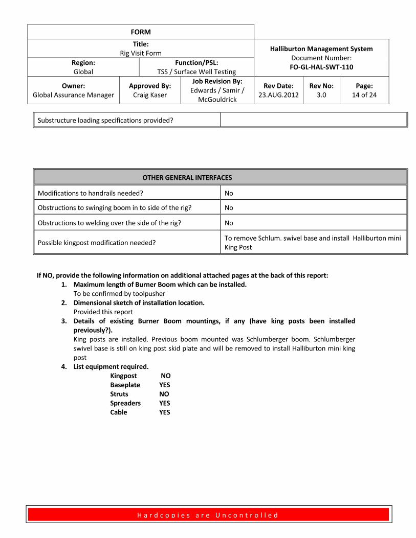
Substructure loading specifications provided?
OTHER GENERAL INTERFACES
Modifications to handrails needed? No
Obstructions to swinging boom in to side of the rig? No
Obstructions to welding over the side of the rig? No
Possible kingpost modification needed? To remove Schlum. swivel base and install Halliburton mini King Post
If NO, provide the following information on additional attached pages at the back of this report: 1. Maximum length of Burner Boom which can be installed.
To be confirmed by toolpusher 2. Dimensional sketch of installation location.
Provided this report 3. Details of existing Burner Boom mountings, if any (have king posts been installed
previously?). King posts are installed. Previous boom mounted was Schlumberger boom. Schlumberger swivel base is still on king post skid plate and will be removed to install Halliburton mini king post
4. List equipment required. Kingpost NO Baseplate YES Struts NO Spreaders YES Cable YES
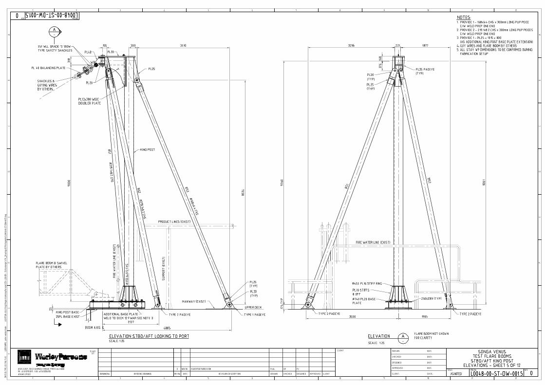
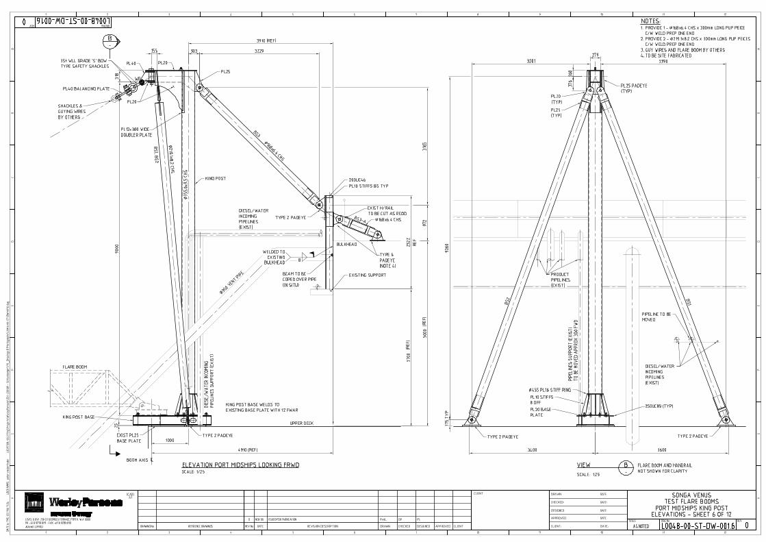
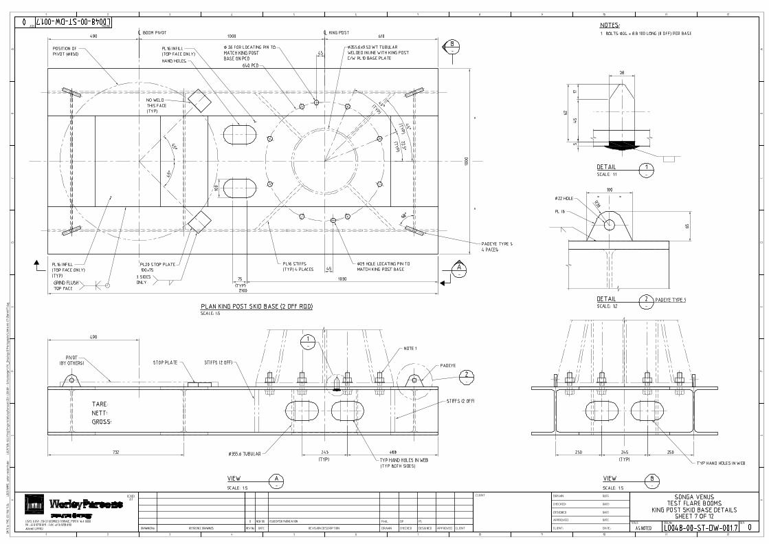
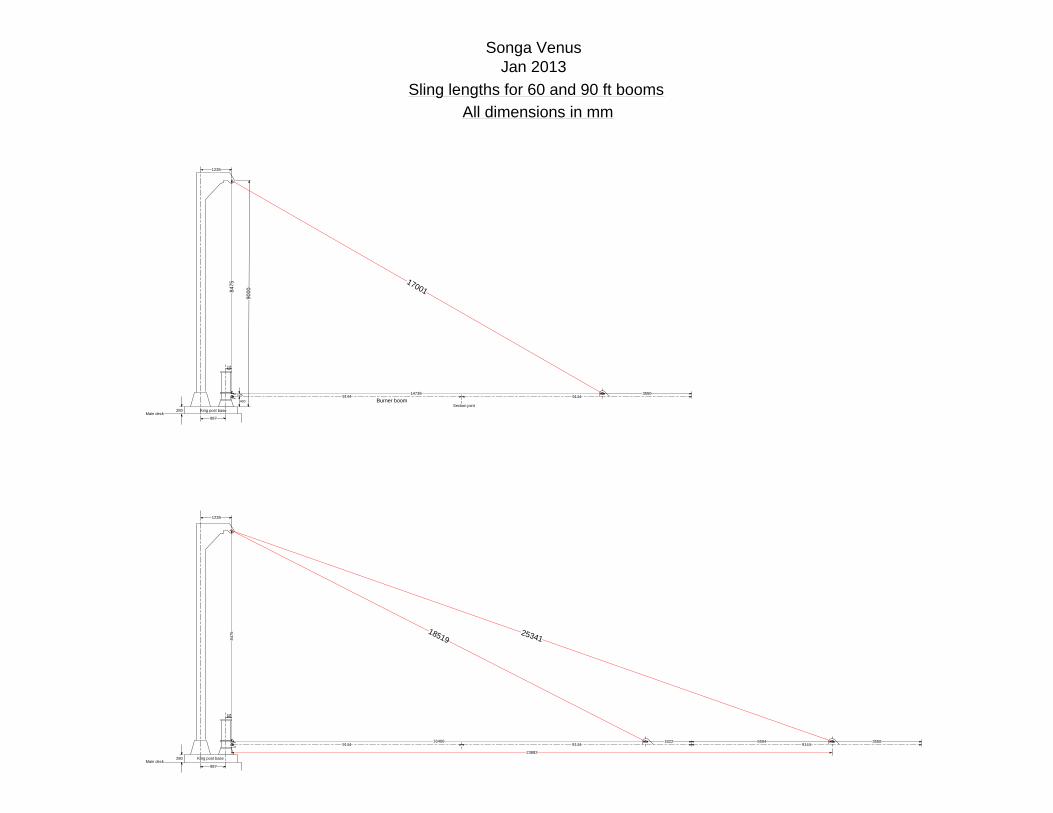
16466
84
7584
75
14738
987
1235
248
9144 9144 91445594
2534118519
23882
280
987
1235
248
9144 9144
280
17001
Sling lengths for 60 and 90 ft booms
All dimensions in mm
125
400
900 0
3550
Burner boomSection joint
1822 3550
Main deck
Main deckKing post base
King post base
Songa VenusJan 2013
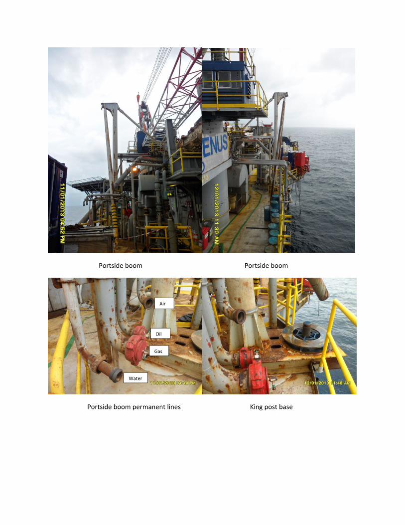
Portside boom Portside boom
Portside boom permanent lines King post base
Gas
Oil
Air
Water
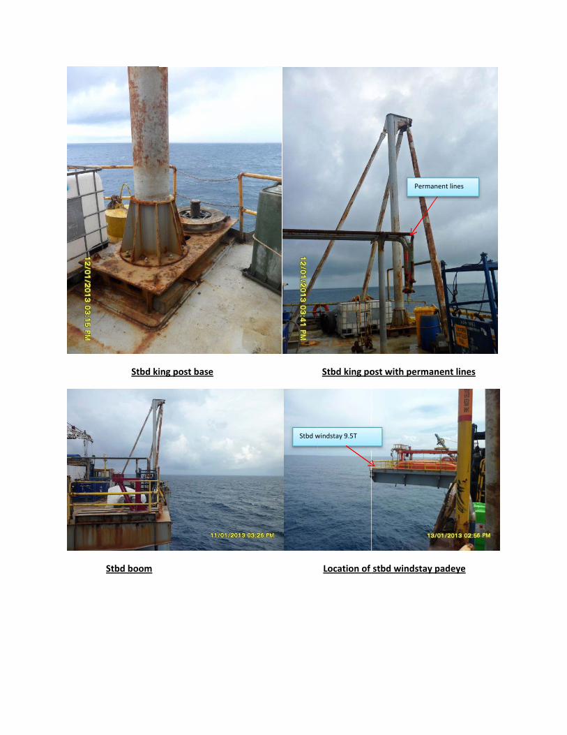
Stbd ki
Stbd boom
ing post base
e
Stbd w
Stbd king po
Location of
windstay 9.5T
ost with perm
stbd windsta
Per
manent lines
ay padeye
rmanent lines
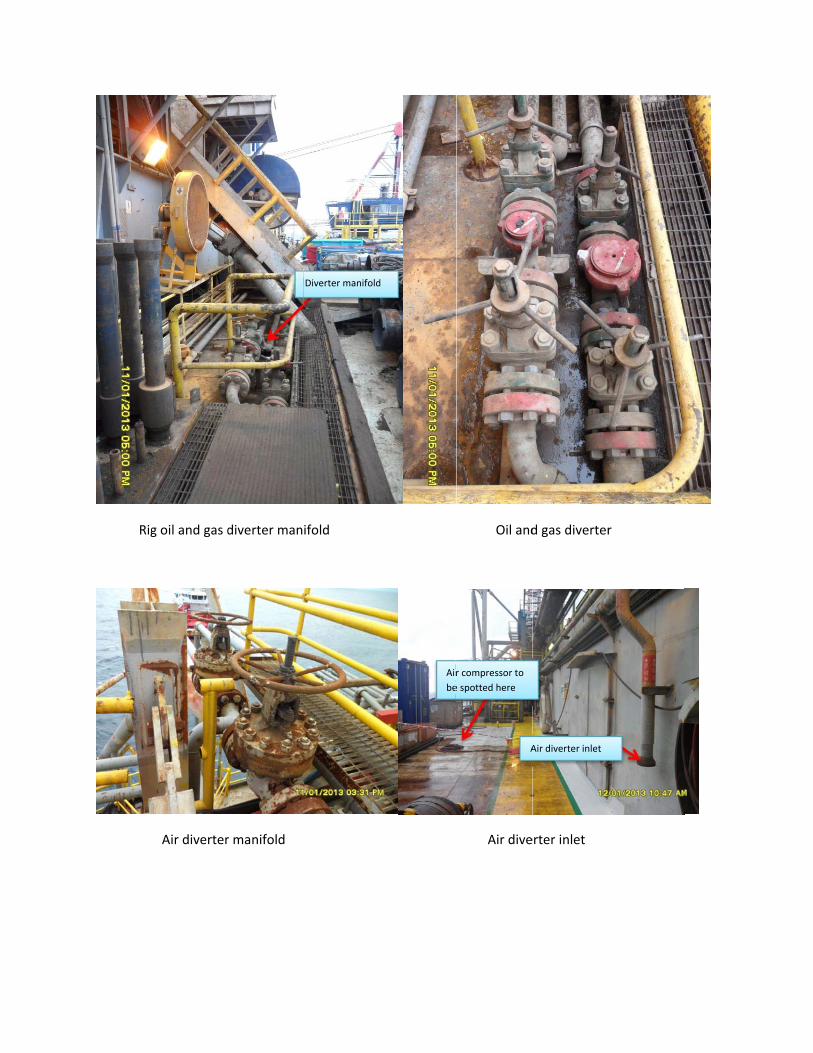
Rig
g oil and gas d
Air diverter
diverter man
r manifold
ifold
Diverter manifold
d
Air
be
Oil and
Air dive
r compressor to
e spotted here
A
d gas diverter
erter inlet
Air diverter inlet
r
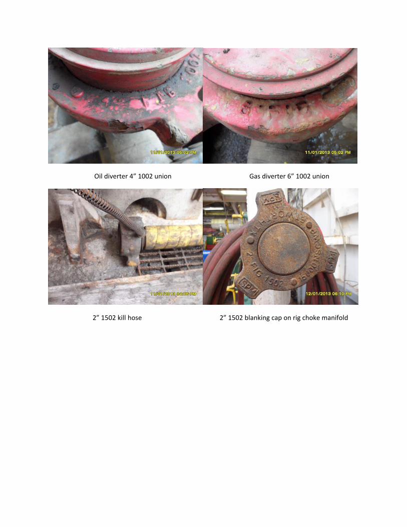
Oil diverter 4” 1002 union Gas diverter 6” 1002 union
2” 1502 kill hose 2” 1502 blanking cap on rig choke manifold
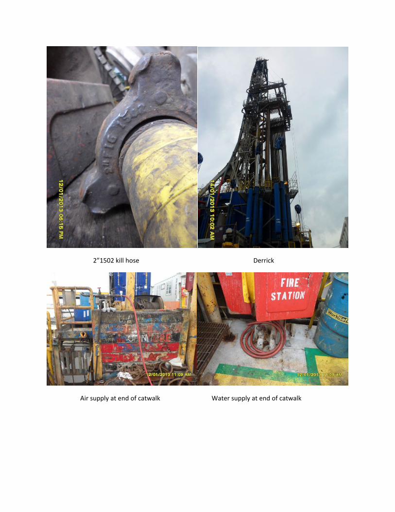
2”1502 kill hose Derrick
Air supply at end of catwalk Water supply at end of catwalk
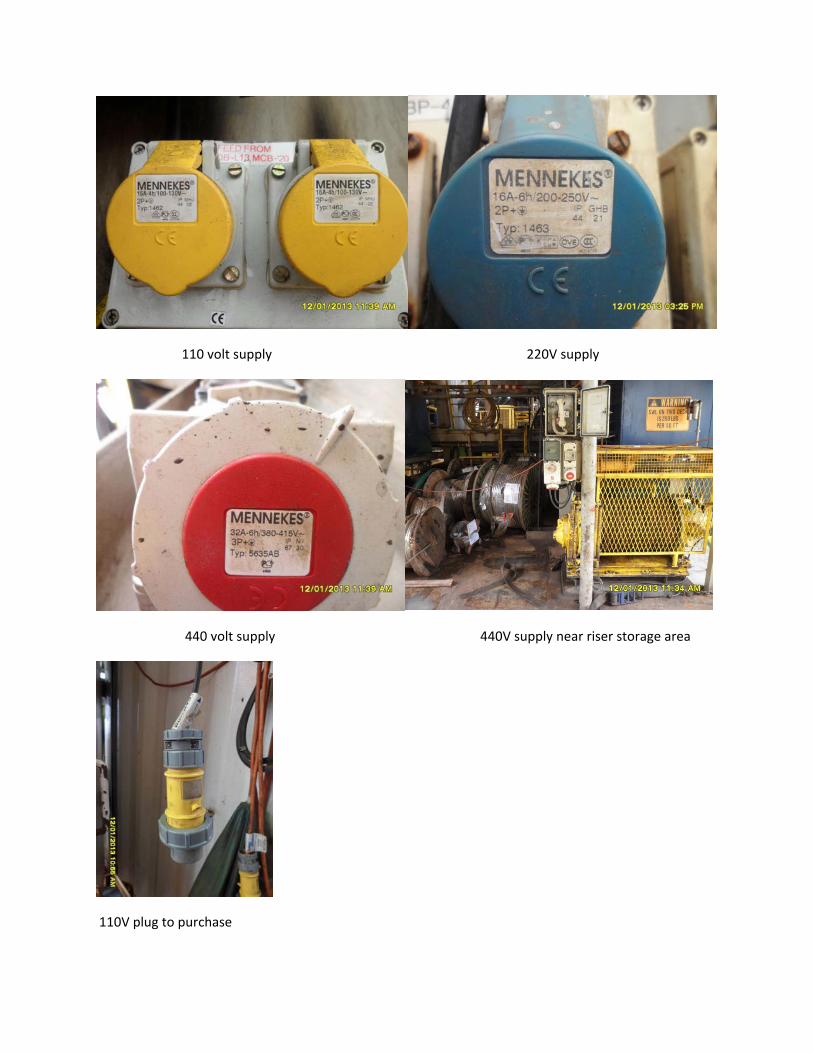
110 volt supply 220V supply
440 volt supply 440V supply near riser storage area
110V plug to purchase
FORM
Title: Rig Visit Form
Halliburton Management System Document Number: FO‐GL‐HAL‐SWT‐110
Region: Global
Function/PSL: TSS / Surface Well Testing
Owner: Global Assurance Manager
Approved By: Craig Kaser
Job Revision By: Edwards / Samir /
McGouldrick
Rev Date: 23.AUG.2012
Rev No: 3.0
Page: 15 of 24
H a r d c o p i e s a r e U n c o n t r o l l e d
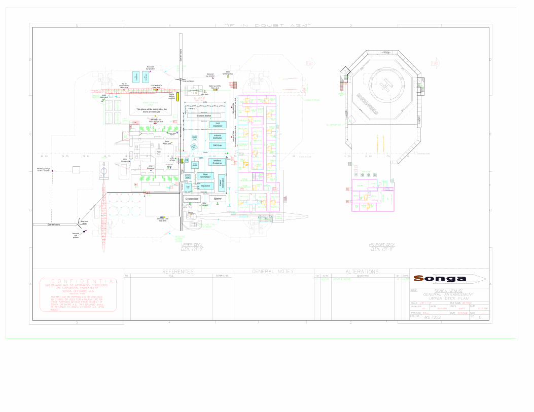
Surface Well Test EQUIPMENT AREA Where possible, obtain copies of the following:
1. Deck Loading Restrictions Drawing(s). Provided in report
2. Pictures of kingpost deck area(s). Provided in report
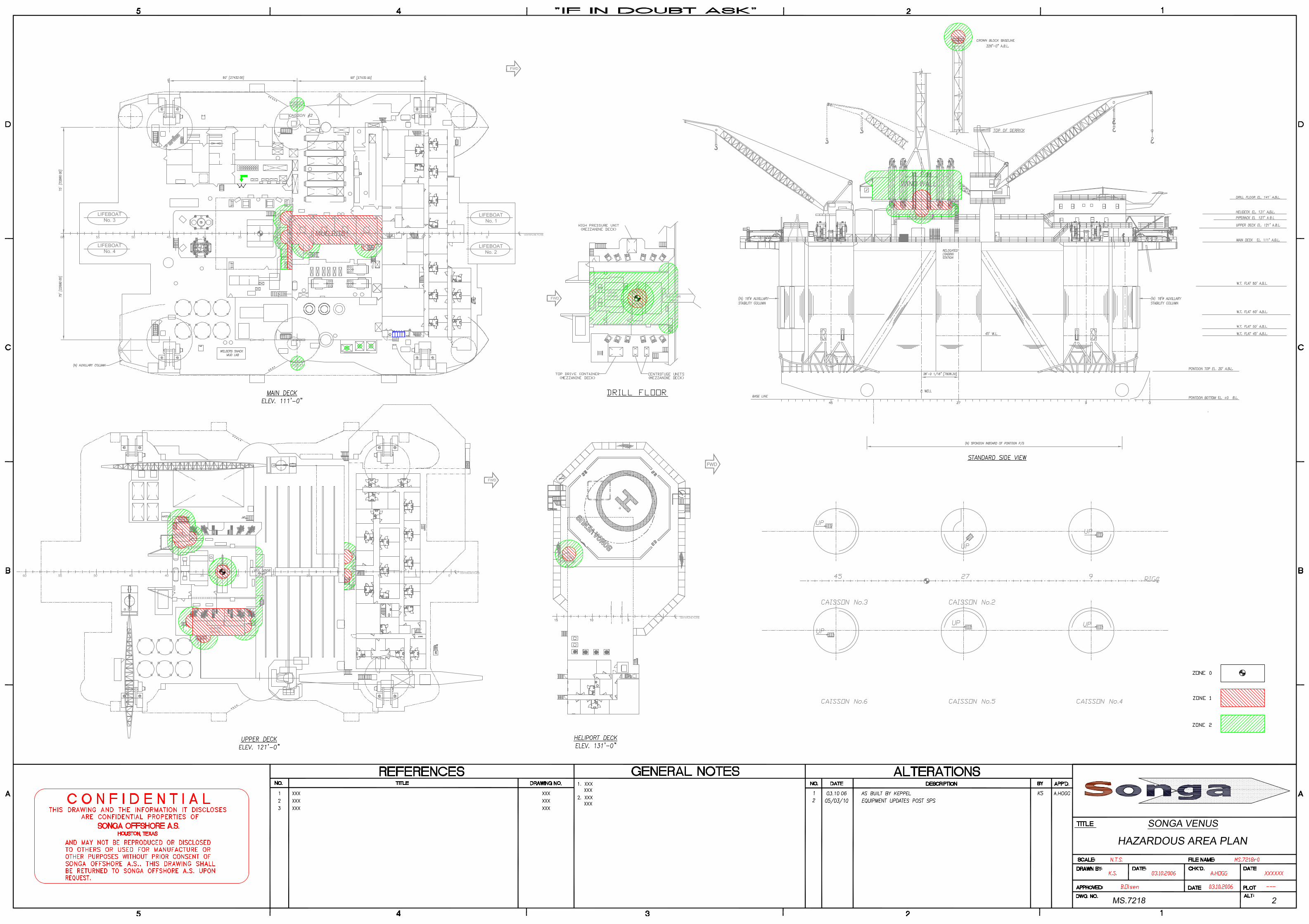
3. Pictures of port and starboard cranes and pedestals. 4. Hazardous Area Drawing(s).
Provided in report 5. Deck plan showing port and starboard crane radii.
Provided in report 6. Surface Well Test Equipment Area Drawing(s).
Provided in report
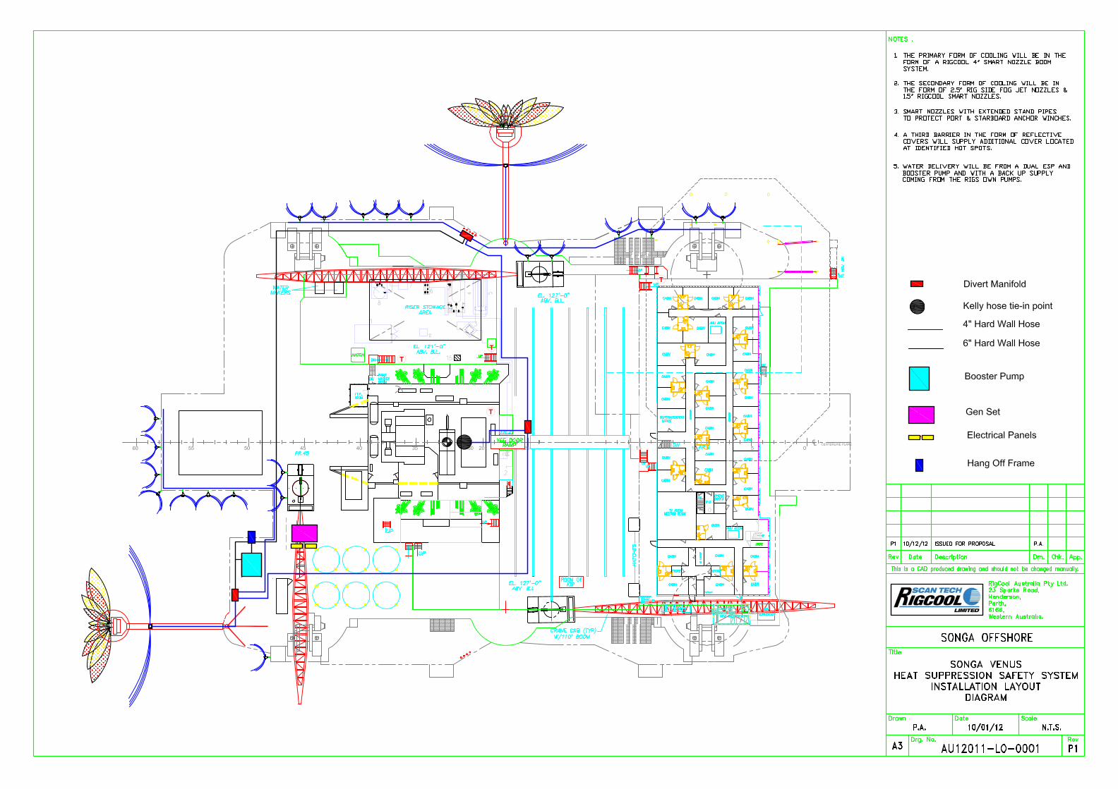
Provide Dimensional Sketch of Equipment Area and Proposed Equipment Layout in space below. Indicate location of nearest air, electrical and fuel supplies. Any additional information should be provided on attached pages at the back of this report.
UPPER DECK LOADS
SeparatorSurge Tank
DAS Lab
Heat Exchanger
Ste
am
G
ener
ato
r
Welltest Container
Air
Com
pre
sso
r
Air
Com
pres
sor
SSV
1 5 1 0 5 0
BHD LWR QTRS
BHD UPPER QTRS
5 0 4 5 4 0 3 03 5 2 5 1 52 0 1 0 5 05 56 0
Subsea
Reel
Subsea Control Panel
DST Container
Stanchions
Geoservices Sperry
Choke Manifold
Subsea Container
Subsea basket
Sep relief
Tank
vent
line
Transfer Pump
Ta
nk
ven
t lin
eR
ig G
as/O
il D
iver
ter
Heater relief
Oil
Relief
Gas
Tan
k R
elie
f
110VMain deck
This place will be empty after the risers are removed
380-415V 32ARiser storage deck
220V and 110VMain deck
220V Moonpool
220V Moonpool
38
0-4
15
V 3
2AA
ccom
oda
tion
an
d t
est
de
ck
38
0-4
15
V 3
2A
Acc
om
od
atio
n a
nd
te
st d
eck
110VTest deck
110V and 440VMain deck
Windstay padeye for 9.5T shackle
Rig Air diverter manifold
Air
Water
Diesel
Air Air
110VMoon pool
Air
110V and 440V Main deck
110V Welding shop
80.5"
Rig air manifold inlet
Main deck
Air and waterRig floor
Air and WaterRig floor
AirRig floor air tugger
Bea
m h
eigh
t 19
"
110V Test deck
Bur
ner
bo
om
King post struts
King post struts
New pad eye
position
New pad eye position
New pad eye position
Burner boom
ES
D
pane
l
48.3ft
90.5"80.5" 90.5"90.5"80.5"
8"
45.3
ft
26ft
Stanchions
10ft
Stanchions
10f
t
Stanchions
Rotary Catwalk
FORM
Title: Rig Visit Form
Halliburton Management System Document Number: FO‐GL‐HAL‐SWT‐110
Region: Global
Function/PSL: TSS / Surface Well Testing
Owner: Global Assurance Manager
Approved By: Craig Kaser
Job Revision By: Edwards / Samir /
McGouldrick
Rev Date: 23.AUG.2012
Rev No: 3.0
Page: 16 of 24
H a r d c o p i e s a r e U n c o n t r o l l e d
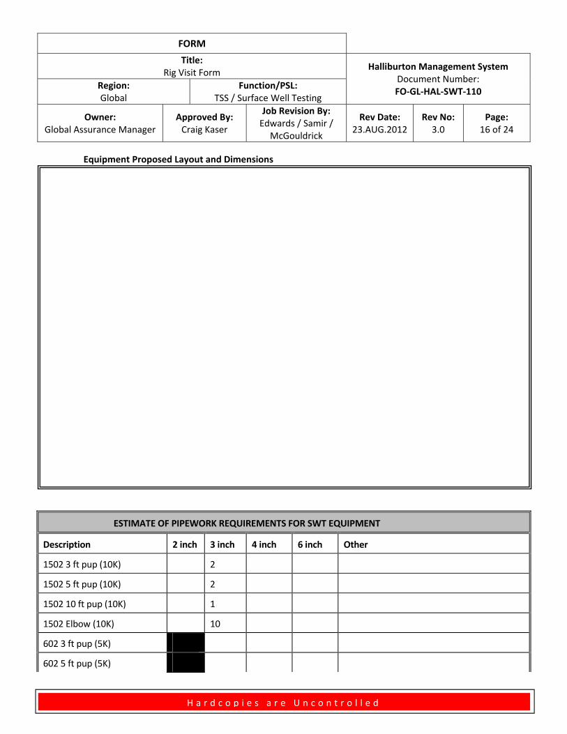
Equipment Proposed Layout and Dimensions
ESTIMATE OF PIPEWORK REQUIREMENTS FOR SWT EQUIPMENT
Description 2 inch 3 inch 4 inch 6 inch Other
1502 3 ft pup (10K) 2
1502 5 ft pup (10K) 2
1502 10 ft pup (10K) 1
1502 Elbow (10K) 10
602 3 ft pup (5K)
602 5 ft pup (5K)
FORM
Title: Rig Visit Form
Halliburton Management System Document Number: FO‐GL‐HAL‐SWT‐110
Region: Global
Function/PSL: TSS / Surface Well Testing
Owner: Global Assurance Manager
Approved By: Craig Kaser
Job Revision By: Edwards / Samir /
McGouldrick
Rev Date: 23.AUG.2012
Rev No: 3.0
Page: 17 of 24
H a r d c o p i e s a r e U n c o n t r o l l e d
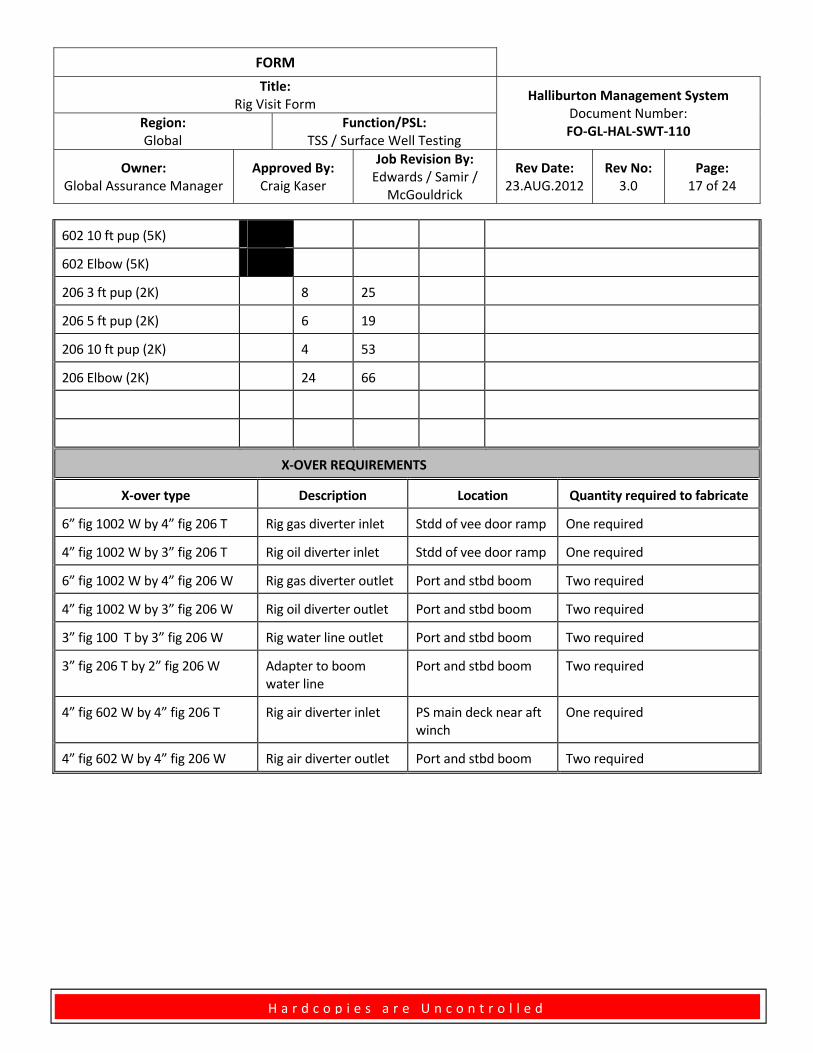
602 10 ft pup (5K)
602 Elbow (5K)
206 3 ft pup (2K) 8 25
206 5 ft pup (2K) 6 19
206 10 ft pup (2K) 4 53
206 Elbow (2K) 24 66
X‐OVER REQUIREMENTS
X‐over type Description Location Quantity required to fabricate
6” fig 1002 W by 4” fig 206 T Rig gas diverter inlet Stdd of vee door ramp One required
4” fig 1002 W by 3” fig 206 T Rig oil diverter inlet Stdd of vee door ramp One required
6” fig 1002 W by 4” fig 206 W Rig gas diverter outlet Port and stbd boom Two required
4” fig 1002 W by 3” fig 206 W Rig oil diverter outlet Port and stbd boom Two required
3” fig 100 T by 3” fig 206 W Rig water line outlet Port and stbd boom Two required
3” fig 206 T by 2” fig 206 W Adapter to boom water line
Port and stbd boom Two required
4” fig 602 W by 4” fig 206 T Rig air diverter inlet PS main deck near aft winch
One required
4” fig 602 W by 4” fig 206 W Rig air diverter outlet Port and stbd boom Two required
FORM
Title: Rig Visit Form
Halliburton Management System Document Number: FO‐GL‐HAL‐SWT‐110
Region: Global
Function/PSL: TSS / Surface Well Testing
Owner: Global Assurance Manager
Approved By: Craig Kaser
Job Revision By: Edwards / Samir /
McGouldrick
Rev Date: 23.AUG.2012
Rev No: 3.0
Page: 18 of 24
H a r d c o p i e s a r e U n c o n t r o l l e d
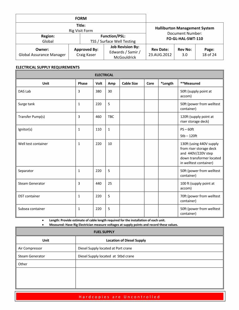
ELECTRICAL SUPPLY REQUIREMENTS
ELECTRICAL
Unit Phase Volt Amp Cable Size Core *Length **Measured
DAS Lab 3 380 30 50ft (supply point at accom)
Surge tank 1 220 5 50ft (power from welltest container)
Transfer Pump(s) 3 460 TBC 120ft (supply point at riser storage deck)
Ignitor(s) 1 110 1 PS – 60ft
Stb – 120ft
Well test container 1 220 10 130ft (using 440V supply from riser storage deck and 440V/220V step down transformer located in welltest container)
Separator 1 220 5 50ft (power from welltest container)
Steam Generator 3 440 25 100 ft (supply point at accom)
DST container 1 220 5 70ft (power from welltest container)
Subsea container 1 220 5 50ft (power from welltest container)
Length: Provide estimate of cable length required for the installation of each unit.
Measured: Have Rig Electrician measure voltages at supply points and record these values.
FUEL SUPPLY
Unit Location of Diesel Supply
Air Compressor Diesel Supply located at Port crane
Steam Generator Diesel Supply located at Stbd crane
Other
FORM
Title: Rig Visit Form
Halliburton Management System Document Number: FO‐GL‐HAL‐SWT‐110
Region: Global
Function/PSL: TSS / Surface Well Testing
Owner: Global Assurance Manager
Approved By: Craig Kaser
Job Revision By: Edwards / Samir /
McGouldrick
Rev Date: 23.AUG.2012
Rev No: 3.0
Page: 19 of 24
H a r d c o p i e s a r e U n c o n t r o l l e d
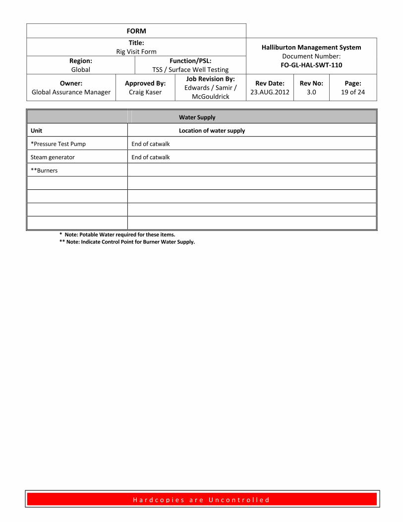
Water Supply
Unit Location of water supply
*Pressure Test Pump End of catwalk
Steam generator End of catwalk
**Burners
* Note: Potable Water required for these items. ** Note: Indicate Control Point for Burner Water Supply.
FORM
Title: Rig Visit Form
Halliburton Management System Document Number: FO‐GL‐HAL‐SWT‐110
Region: Global
Function/PSL: TSS / Surface Well Testing
Owner: Global Assurance Manager
Approved By: Craig Kaser
Job Revision By: Edwards / Samir /
McGouldrick
Rev Date: 23.AUG.2012
Rev No: 3.0
Page: 20 of 24
H a r d c o p i e s a r e U n c o n t r o l l e d
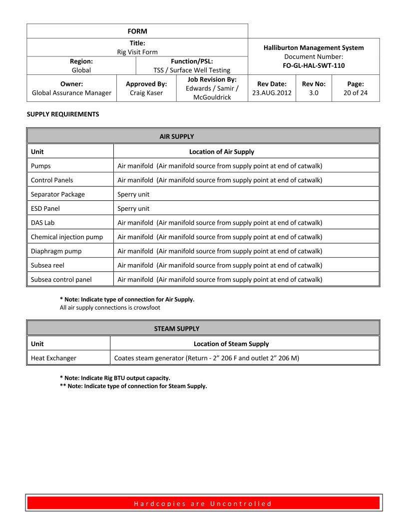
SUPPLY REQUIREMENTS
AIR SUPPLY
Unit Location of Air Supply
Pumps Air manifold (Air manifold source from supply point at end of catwalk)
Control Panels Air manifold (Air manifold source from supply point at end of catwalk)
Separator Package Sperry unit
ESD Panel Sperry unit
DAS Lab Air manifold (Air manifold source from supply point at end of catwalk)
Chemical injection pump Air manifold (Air manifold source from supply point at end of catwalk)
Diaphragm pump Air manifold (Air manifold source from supply point at end of catwalk)
Subsea reel Air manifold (Air manifold source from supply point at end of catwalk)
Subsea control panel Air manifold (Air manifold source from supply point at end of catwalk)
* Note: Indicate type of connection for Air Supply. All air supply connections is crowsfoot
STEAM SUPPLY
Unit Location of Steam Supply
Heat Exchanger Coates steam generator (Return ‐ 2” 206 F and outlet 2” 206 M)
* Note: Indicate Rig BTU output capacity. ** Note: Indicate type of connection for Steam Supply.
FORM
Title: Rig Visit Form
Halliburton Management System Document Number: FO‐GL‐HAL‐SWT‐110
Region: Global
Function/PSL: TSS / Surface Well Testing
Owner: Global Assurance Manager
Approved By: Craig Kaser
Job Revision By: Edwards / Samir /
McGouldrick
Rev Date: 23.AUG.2012
Rev No: 3.0
Page: 21 of 24
H a r d c o p i e s a r e U n c o n t r o l l e d
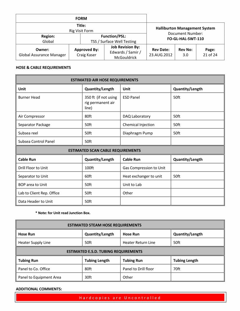
HOSE & CABLE REQUIREMENTS
ESTIMATED AIR HOSE REQUIREMENTS
Unit Quantity/Length Unit Quantity/Length
Burner Head 350 ft (if not using rig permanent air line)
ESD Panel 50ft
Air Compressor 80ft DAQ Laboratory 50ft
Separator Package 50ft Chemical Injection 50ft
Subsea reel 50ft Diaphragm Pump 50ft
Subsea Control Panel 50ft
ESTIMATED SCAN CABLE REQUIREMENTS
Cable Run Quantity/Length Cable Run Quantity/Length
Drill Floor to Unit 100ft Gas Compression to Unit
Separator to Unit 60ft Heat exchanger to unit 50ft
BOP area to Unit 50ft Unit to Lab
Lab to Client Rep. Office 50ft Other
Data Header to Unit 50ft
* Note: for Unit read Junction Box.
ESTIMATED STEAM HOSE REQUIREMENTS
Hose Run Quantity/Length Hose Run Quantity/Length
Heater Supply Line 50ft Heater Return Line 50ft
ESTIMATED E.S.D. TUBING REQUIREMENTS
Tubing Run Tubing Length Tubing Run Tubing Length
Panel to Co. Office 80ft Panel to Drill floor 70ft
Panel to Equipment Area 30ft Other
ADDITIONAL COMMENTS:
FORM
Title: Rig Visit Form
Halliburton Management System Document Number: FO‐GL‐HAL‐SWT‐110
Region: Global
Function/PSL: TSS / Surface Well Testing
Owner: Global Assurance Manager
Approved By: Craig Kaser
Job Revision By: Edwards / Samir /
McGouldrick
Rev Date: 23.AUG.2012
Rev No: 3.0
Page: 22 of 24
H a r d c o p i e s a r e U n c o n t r o l l e d
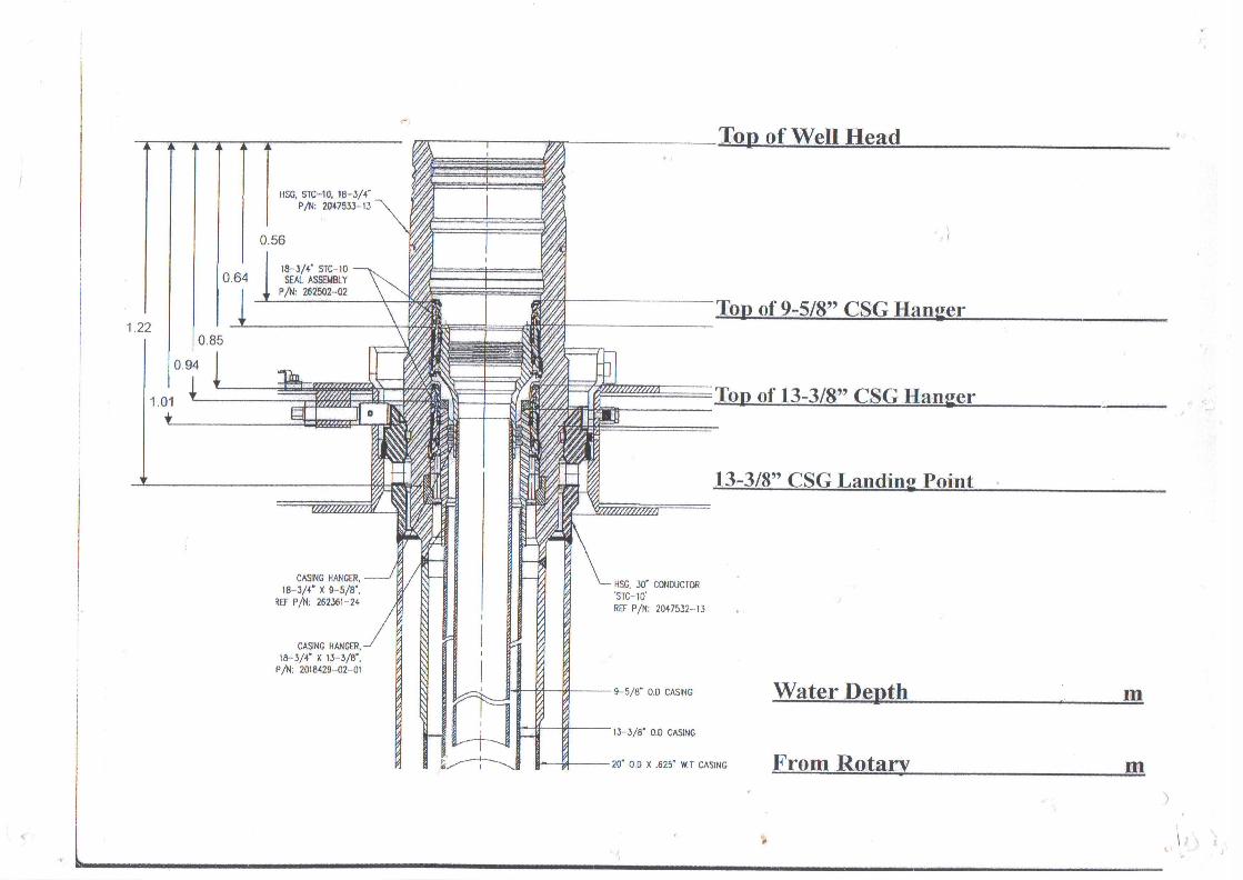
TOP OFWELLHEAD
DATUM
H H
G G
F F
E E
E
F
G
H
A B
C
D
J J
RIG NAME :
STACK TYPE : PRESSURE RATING :
STACK SIZE :
A1
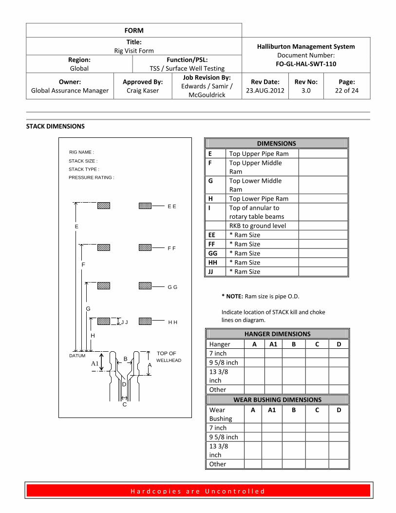
STACK DIMENSIONS
* NOTE: Ram size is pipe O.D.
Indicate location of STACK kill and choke lines on diagram.
DIMENSIONS
E Top Upper Pipe Ram
F Top Upper Middle Ram
G Top Lower Middle Ram
H Top Lower Pipe Ram
I Top of annular to rotary table beams
RKB to ground level
EE * Ram Size
FF * Ram Size
GG * Ram Size
HH * Ram Size
JJ * Ram Size
HANGER DIMENSIONS
Hanger A A1 B C D
7 inch
9 5/8 inch
13 3/8 inch
Other
WEAR BUSHING DIMENSIONS
Wear Bushing
A A1 B C D
7 inch
9 5/8 inch
13 3/8 inch
Other
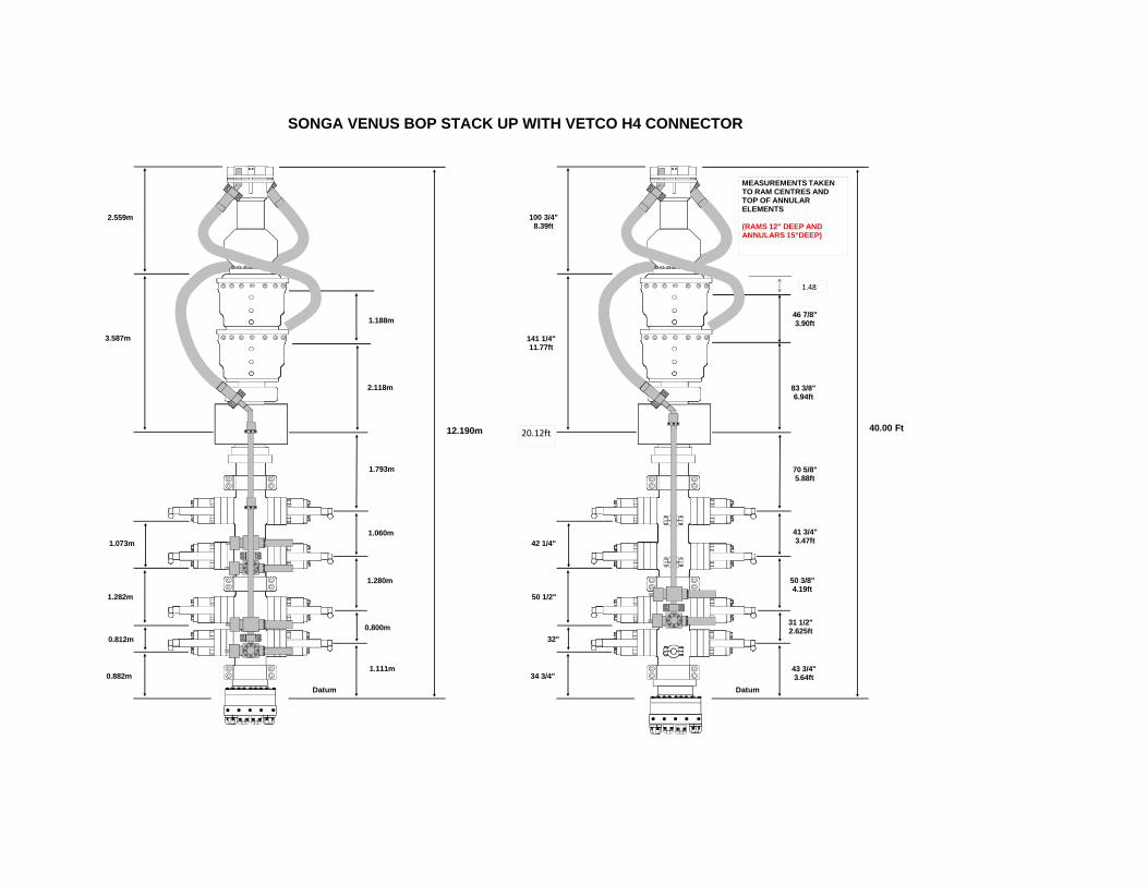
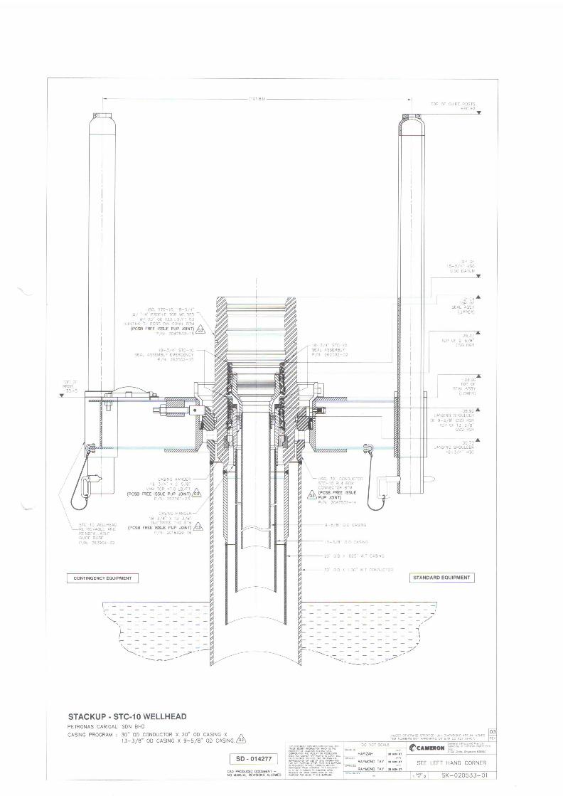
SONGA VENUS BOP STACK UP WITH VETCO H4 CONNECTOR
1.188m
2.118m
1.793m
1.060m
1.280m
0.800m
1.111m0.882m
0.812m
1.282m
1.073m
3.587m
2.559m
Datum
46 7/8"3.90ft
83 3/8"6.94ft
70 5/8"5.88ft
41 3/4"3.47ft
50 3/8"4.19ft
31 1/2"2.625ft
43 3/4"3.64ft34 3/4"
32"
50 1/2"
42 1/4"
141 1/4"11.77ft
100 3/4"8.39ft
Datum
12.190m 40.00 Ft
MEASUREMENTS TAKEN TO RAM CENTRES AND TOP OF ANNULAR ELEMENTS
(RAMS 12" DEEP AND ANNULARS 15"DEEP)
1.48
20.12ft
FORM
Title: Rig Visit Form
Halliburton Management System Document Number: FO‐GL‐HAL‐SWT‐110
Region: Global
Function/PSL: TSS / Surface Well Testing
Owner: Global Assurance Manager
Approved By: Craig Kaser
Job Revision By: Edwards / Samir /
McGouldrick
Rev Date: 23.AUG.2012
Rev No: 3.0
Page: 23 of 24
H a r d c o p i e s a r e U n c o n t r o l l e d
* NOTE: D is angle of Hang‐off shoulder
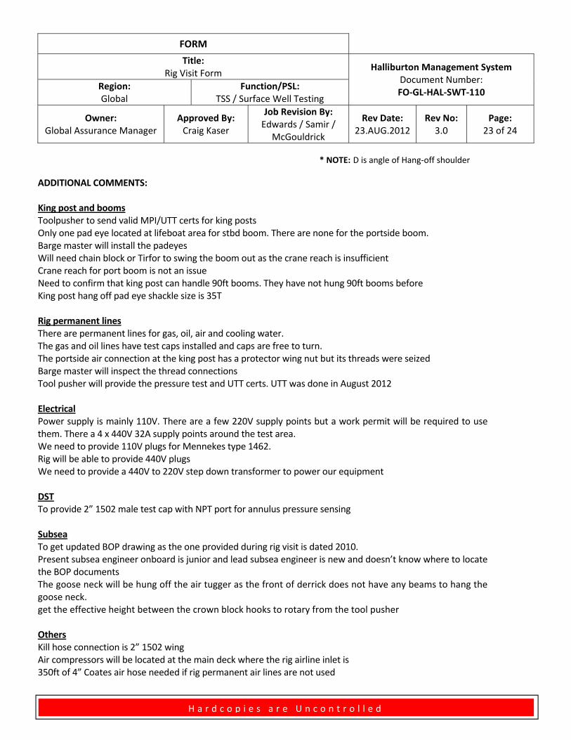
ADDITIONAL COMMENTS: King post and booms Toolpusher to send valid MPI/UTT certs for king posts Only one pad eye located at lifeboat area for stbd boom. There are none for the portside boom. Barge master will install the padeyes Will need chain block or Tirfor to swing the boom out as the crane reach is insufficient Crane reach for port boom is not an issue Need to confirm that king post can handle 90ft booms. They have not hung 90ft booms before King post hang off pad eye shackle size is 35T Rig permanent lines There are permanent lines for gas, oil, air and cooling water. The gas and oil lines have test caps installed and caps are free to turn. The portside air connection at the king post has a protector wing nut but its threads were seized Barge master will inspect the thread connections Tool pusher will provide the pressure test and UTT certs. UTT was done in August 2012 Electrical Power supply is mainly 110V. There are a few 220V supply points but a work permit will be required to use them. There a 4 x 440V 32A supply points around the test area. We need to provide 110V plugs for Mennekes type 1462. Rig will be able to provide 440V plugs We need to provide a 440V to 220V step down transformer to power our equipment DST To provide 2” 1502 male test cap with NPT port for annulus pressure sensing Subsea To get updated BOP drawing as the one provided during rig visit is dated 2010. Present subsea engineer onboard is junior and lead subsea engineer is new and doesn’t know where to locate the BOP documents The goose neck will be hung off the air tugger as the front of derrick does not have any beams to hang the goose neck. get the effective height between the crown block hooks to rotary from the tool pusher Others Kill hose connection is 2” 1502 wing Air compressors will be located at the main deck where the rig airline inlet is 350ft of 4” Coates air hose needed if rig permanent air lines are not used
FORM
Title: Rig Visit Form
Halliburton Management System Document Number: FO‐GL‐HAL‐SWT‐110
Region: Global
Function/PSL: TSS / Surface Well Testing
Owner: Global Assurance Manager
Approved By: Craig Kaser
Job Revision By: Edwards / Samir /
McGouldrick
Rev Date: 23.AUG.2012
Rev No: 3.0
Page: 24 of 24
H a r d c o p i e s a r e U n c o n t r o l l e d
Revision Log Date Revision Description Rev # Revised By
9.JAN.2011 Release to Production 2.0 Boyer
23.AUG.2012 Updated to latest HMS format 3.0 Kaser / ten Hoope
14.SEP.2012 Added “Type of Crane” to Main Deck Test Area Added Kingpost Installation Section Added “Hazardous Area Drawing(s), Deck plan showing port and starboard crane radii, and Surface Well Test Equipment Area Drawing(s)” to the obtain copies section of the Surface Well Test Equipment Area section.
3.1 Edwards / Samir / McGouldrick