Embed Size (px)
Citation preview

700 DrillConceptual Design Review
November 23, 2020

Science Requirements1. Target depths: from the surface to a potential maximum of 700 m depth
2. Ice core diameter: 64 mm
3. Core length: 1 m
4. The drill should be operable in ice temperatures down to -25 C.
5. The surface equipment should be operable in ambient temperatures from -20 to +5 C.
6. All electrical connections and control boxes should be sealed to function well in environments with high levels of humidity, e.g. in
tropical sites.
7. Air transport type: Bell 212 or similar helicopter and/or Twin Otter
8. Drilling fluid: drill should be compatible with existing fluids, e.g. Isopar K, Estisol 140
9. Maximum field project duration: 2 months on-site with at least 40 days of production drilling. Target core recovery is 700 m
within a single ~60-day field season.
10. Core quality requirements:
a. Core recovery over the entire borehole, as close as possible
b. Ice pieces to fit together snugly without any gaps
c. In non-brittle ice, the packed core should have no more than 12 pieces of ice per 10 m section of core
d. In brittle ice, there may be a lot of pieces in a single ~2 m core segment, but the pieces must fit together, retaining
stratigraphic order; more than 80% of the ice volume must be in pieces that each have a volume > 2 liters
11. Absolute borehole depth measurement accuracy: 0.2% of depth
12. Field set-up time: the system should be able to be set up with no more than five persons with limited logistics (i.e. no heavy
equipment), including surface infrastructure and any core handling/processing setup
13. Core processing equipment will be included with the drill system.
14. Core packaging materials (tubes, boxes, straps) and transportation materials (pallets, blankets) shall be provided by the logistics
provider.
15. The core will be transported from the site in the same season it is drilled.16. System should include the capability to bail fluid from the borehole. 17. Borehole should accommodate logging instruments after ice coring is complete. 18. Drill system should operate with either a generator or a renewable source, and a lightweight portable renewable source should
be provided, e.g. flexible or folding solar panels. 19. Borehole temperature (±0.1 C or better)* and borehole inclination (±0.5 degrees or better) should be measured and recorded.
700 Drill Conceptual Design Review 2
Changes from the Foro 700 Science Requirements are shown in red
* The temperature sensor in the Foro drills has an accuracy of ±0.5 C
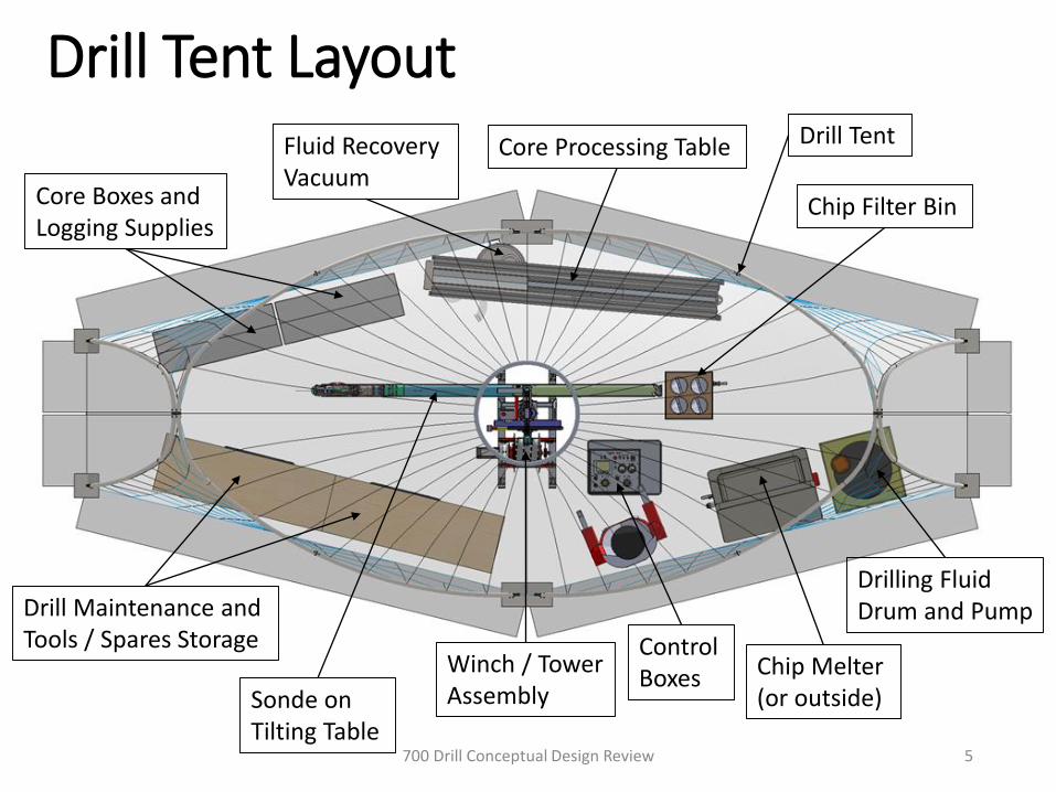
SafetySafety of personnel using this drill is paramount:
• Hazardous nature of the operations
• Severe environmental conditions at the field sites
• Extremely long travel times to advanced medical care and life support facilities
• Small mishaps may have severe consequences in this environment
Safety Requirements:
1. Create a safety plan that defines how key issues for the project will be identified, managed, assessed and addressed during the system development.
2. Conduct a Failure Modes and Effects Analysis (FMEA) to identify and manage mechanical/physical/chemical and personnel hazards for the system.
3. Provide operational and safety trainings, as identified by the FMEA, to address safety hazards.
4. Provide operational and safety trainings, as identified by the FMEA, to address quality issues.
5. Provide hardware and/or software protection devices to prevent damage to the equipment due to overloads in the system, such as torque limiters, over-current protection, and limit switches.
6. Provide appropriate Personal Protective Equipment (PPE) for operating the drill system and handling drilling fluids, as identified in the FMEA.
7. Minimize environmental impact of the drilling operations through mitigations identified in the FMEA.
8. Provide identification of and protection from dangerous voltages.
9. Provide safety interlocks (Lock-Outs) to prevent the in-advertent operation of equipment that would endanger personnel.
10. Provide emergency stop and emergency power-off systems to respectively halt and power-off the equipment in the case of an emergency. The emergency power-off systems in some cases must have fail-safe brakes such that the removal of the power will engage the brakes. (Examples include the winch or tower mechanisms, which must engage the brakes and hold their last position in case of a loss of power.)
11. Create an operations plan and procedures for normal drilling and surface operations of the system.
12. Create safety and maintenance check lists that will be completed at defined intervals to verify safety equipment is in place and the drill system is in proper working order.
700 Drill Conceptual Design Review 3

System Description New drill system with smaller diameter sonde based on the existing
Foro 1650 (IDD) for mid-range ice coring to 700 m depth.
Incorporates designs from existing drill systems wherever possible.
Primary focus on minimizing weight and logistics requirements to make it possible to access sites with limited logistics and seasons as short as two months in length.
700 Drill Conceptual Design Review 4
Drill Tent Layout
700 Drill Conceptual Design Review 5
Core Boxes and Logging Supplies
Core Processing TableFluid Recovery Vacuum
Chip Filter Bin
Drill Maintenance and Tools / Spares Storage
Drilling Fluid Drum and Pump
Chip Melter(or outside)
Control Boxes
Drill Tent
Winch / Tower AssemblySonde on
Tilting Table
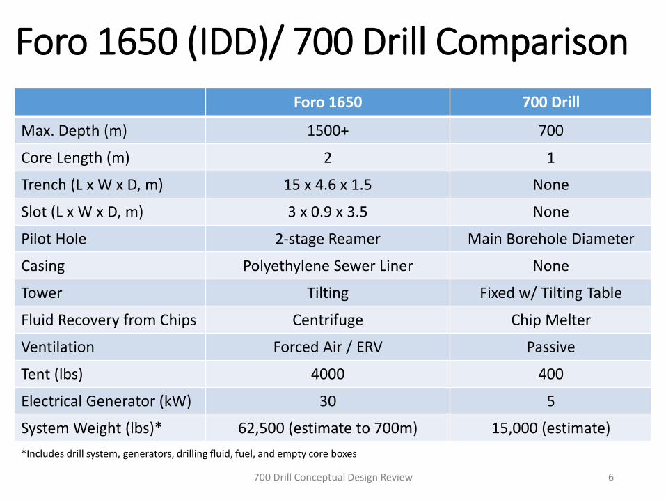
Foro 1650 (IDD)/ 700 Drill Comparison
700 Drill Conceptual Design Review 6
IDD
Foro 1650 700 Drill
Max. Depth (m) 1500+ 700
Core Length (m) 2 1
Trench (L x W x D, m) 15 x 4.6 x 1.5 None
Slot (L x W x D, m) 3 x 0.9 x 3.5 None
Pilot Hole 2-stage Reamer Main Borehole Diameter
Casing Polyethylene Sewer Liner None
Tower Tilting Fixed w/ Tilting Table
Fluid Recovery from Chips Centrifuge Chip Melter
Ventilation Forced Air / ERV Passive
Tent (lbs) 4000 400
Electrical Generator (kW) 30 5
System Weight (lbs)* 62,500 (estimate to 700m) 15,000 (estimate)
*Includes drill system, generators, drilling fluid, fuel, and empty core boxes
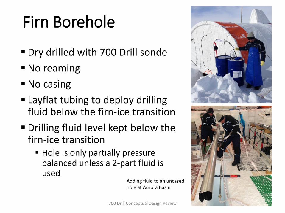
Firn Borehole
Dry drilled with 700 Drill sonde
No reaming
No casing
Layflat tubing to deploy drilling fluid below the firn-ice transition
Drilling fluid level kept below the firn-ice transition Hole is only partially pressure
balanced unless a 2-part fluid is used
700 Drill Conceptual Design Review 7
Adding fluid to an uncased hole at Aurora Basin
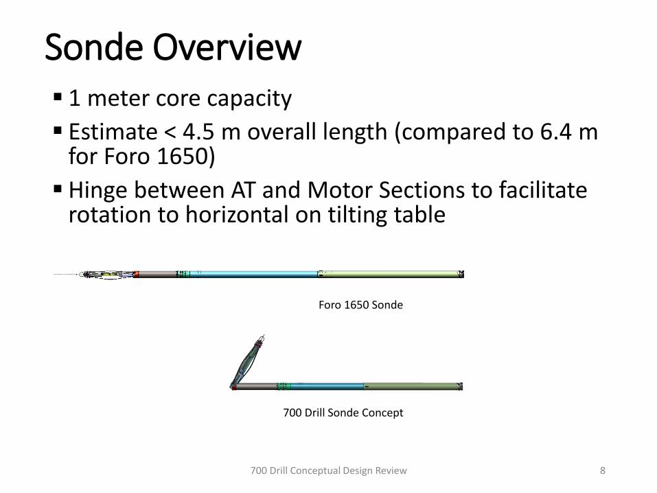
Sonde Overview 1 meter core capacity
Estimate < 4.5 m overall length (compared to 6.4 m for Foro 1650)
Hinge between AT and Motor Sections to facilitate rotation to horizontal on tilting table
700 Drill Conceptual Design Review 8
Foro 1650 Sonde
700 Drill Sonde Concept
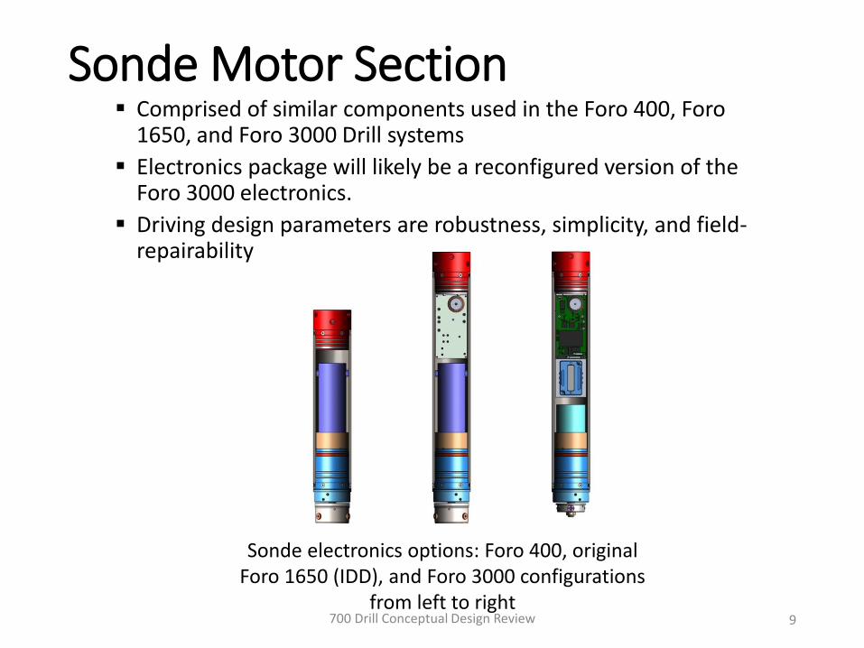
Sonde Motor Section Comprised of similar components used in the Foro 400, Foro
1650, and Foro 3000 Drill systems
Electronics package will likely be a reconfigured version of the Foro 3000 electronics.
Driving design parameters are robustness, simplicity, and field-repairability
700 Drill Conceptual Design Review 9
Sonde electronics options: Foro 400, original Foro 1650 (IDD), and Foro 3000 configurations
from left to right

700 Drill Conceptual Design Review 10
Sonde Motor Section Options
Foro 400 Type Electronics
Original Foro 1650 Type Electronics
Foro 3000 Type Electronics
Motor control method
Off-the-shelf pulse width modulated (PWM) controller on the surface
IDP designed motor power supply (MPS) in the sonde with DC power supply on the surface
IDP designed drill power supply (DPS) with off-the-shelf PWM motor controller and sonde interface electronics in the sonde; DC power supply on the surface
Motor type Brushed DC, 500W Brushed DC, 500W Brushless DC, 500W
Motor functionality
Variable speed forward and reverse
Variable speed forward only without additional development
Variable speed forward and reverse
Other functionality
AT slip sensor AT slip sensor AT slip sensor, temperature and pressure sensors, inclination, motor speed
Positive aspects of design
No down hole electronics; possibly the lowest cost option
Leverages and reuses existing designs; better motor control than Foro 400 option
Leverages and reuses designs already in progress; added feedback from down hole sensors; better motor control than Foro 400 option
Negative aspects of design
Motor controllers are not designed for use over long cables; would require testing to vet option; may add electrical noise into the system; controller may be slow to respond to load changes due to the long cable length; does not currently meet the 700 Drill science requirements
Longer than Foro 400 option; no reverse function without further development; added down hole electronics; requires moderate additional development to downsize for smaller diameter sonde; does not currently meet the 700 Drill science requirements
Longer than Foro 400 option; added down hole electronics; requires substantial additional development to downsize for smaller diameter sonde; may require computer for operation
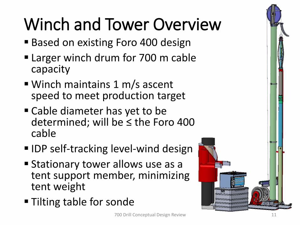
Winch and Tower Overview Based on existing Foro 400 design
Larger winch drum for 700 m cable capacity
Winch maintains 1 m/s ascent speed to meet production target
Cable diameter has yet to be determined; will be ≤ the Foro 400 cable
IDP self-tracking level-wind design
Stationary tower allows use as a tent support member, minimizing tent weight
Tilting table for sonde700 Drill Conceptual Design Review 11
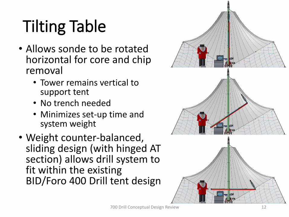
Tilting Table• Allows sonde to be rotated
horizontal for core and chip removal• Tower remains vertical to
support tent• No trench needed• Minimizes set-up time and
system weight
• Weight counter-balanced, sliding design (with hinged AT section) allows drill system to fit within the existing BID/Foro 400 Drill tent design
700 Drill Conceptual Design Review 12
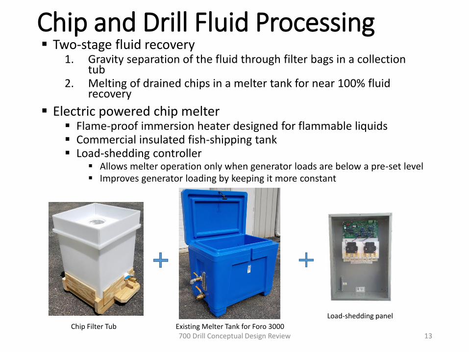
Chip and Drill Fluid Processing Two-stage fluid recovery
1. Gravity separation of the fluid through filter bags in a collection tub
2. Melting of drained chips in a melter tank for near 100% fluid recovery
Electric powered chip melter Flame-proof immersion heater designed for flammable liquids Commercial insulated fish-shipping tank Load-shedding controller
Allows melter operation only when generator loads are below a pre-set level Improves generator loading by keeping it more constant
700 Drill Conceptual Design Review 13Existing Melter Tank for Foro 3000
Load-shedding panel
Chip Filter Tub

Drill Fluid Recovery Cable vacuum to minimize fluid loss on drill ascent Vacuum used to recover fluid off of cores at the core
processing table Drip trays under winch, around tower, under tilting-
table, and on core processing table Bailer attachment to recover drilling fluid from
completed borehole
700 Drill Conceptual Design Review 14
Fluid Vacuum Cable Vacuum Attachment Fluid Bailer Check Valve from ASIG Drill
Drilling Fluid Drill system to be compatible with most drilling
fluids, including Isopar K and Estisol 140
Recommend using Isopar K, with or without a densifier A densifier would be needed to fully pressure-balance
the borehole (max fluid level at firn-ice transition)
Fluid pumped to borehole directly from drums with an electric drum pump Two-part fluids will require additional
mixing/proportioning equipment
700 Drill Conceptual Design Review 15

Core Processing Minimal core processing equipment to save system
weight and size
Core push-out table with logging tray
No electric saw planned, but could be included as needed
Core storage in a separate trench or freezer to avoid the elevated temperatures in the drill tent
700 Drill Conceptual Design Review 16
Tent
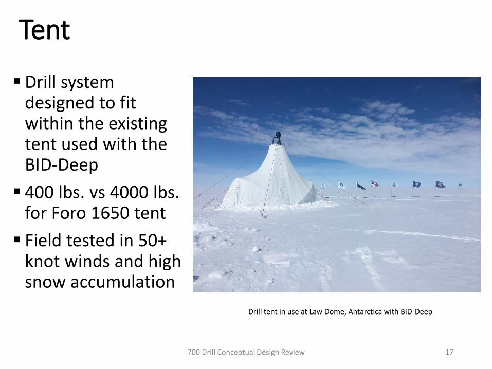
Drill system designed to fit within the existing tent used with the BID-Deep
400 lbs. vs 4000 lbs. for Foro 1650 tent
Field tested in 50+ knot winds and high snow accumulation
700 Drill Conceptual Design Review 17
Drill tent in use at Law Dome, Antarctica with BID-Deep
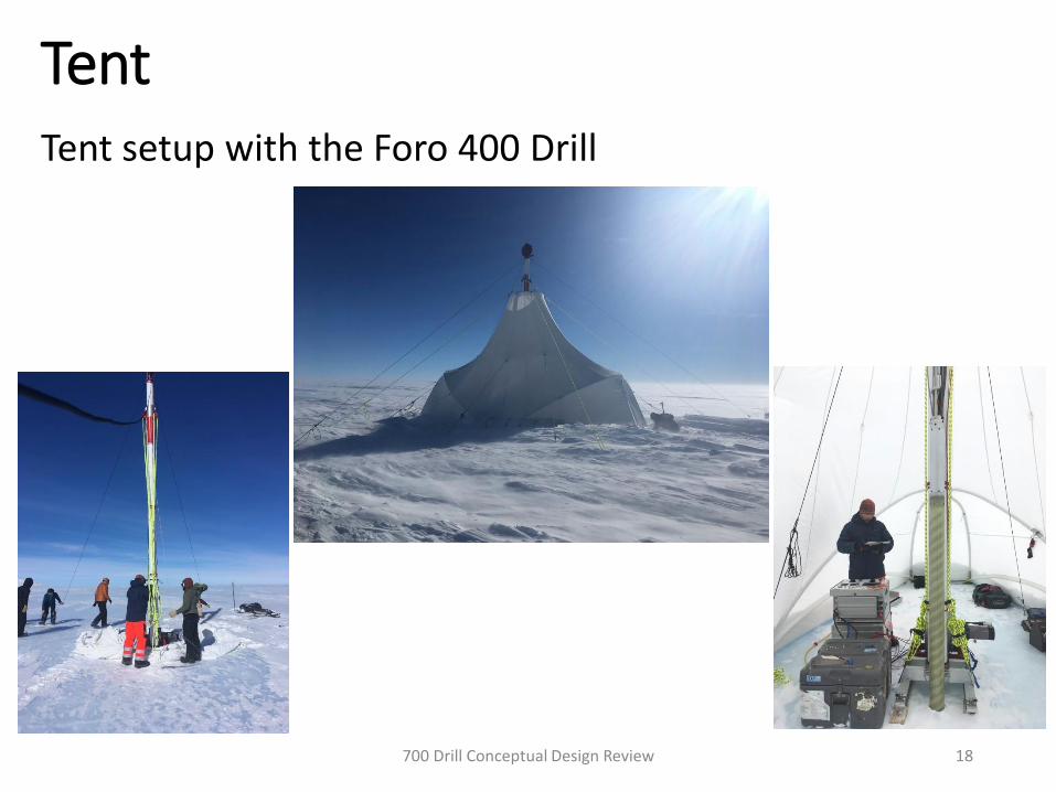
Tent
700 Drill Conceptual Design Review 18
Tent setup with the Foro 400 Drill

Power requirements• The drill system is anticipated to require a 5.0 kW,
240-volt, 1-phase power feed • Load-shedding circuitry will automatically cut-out chip
melter, etc. when max. amperage is needed for core break and sonde ascent• Minimizes generator size and fuel usage
• Spare generator included in system concept
700 Drill Conceptual Design Review 19
5.0 kW gasoline-powered generator

Operations• Drilling and core processing operations will require a 3-person team
• 10 hours per day, single-shift operation is anticipated• 3 people required for operation (2 IDP drillers and 1 science team member)
• Up to 5 people may be needed to safely assemble the drill system
• It is estimated to require less than 40 drilling days to reach 700 m
700 Drill Conceptual Design Review
20
Days
Drill system setup (one 10 hr. shift) 4
Drilling to 700 m (one 10 hr. shift, not including days off) 40
Drill system pack up (one 10 hr. shift) 3
≤
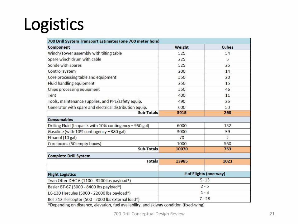
Logistics
700 Drill Conceptual Design Review 21
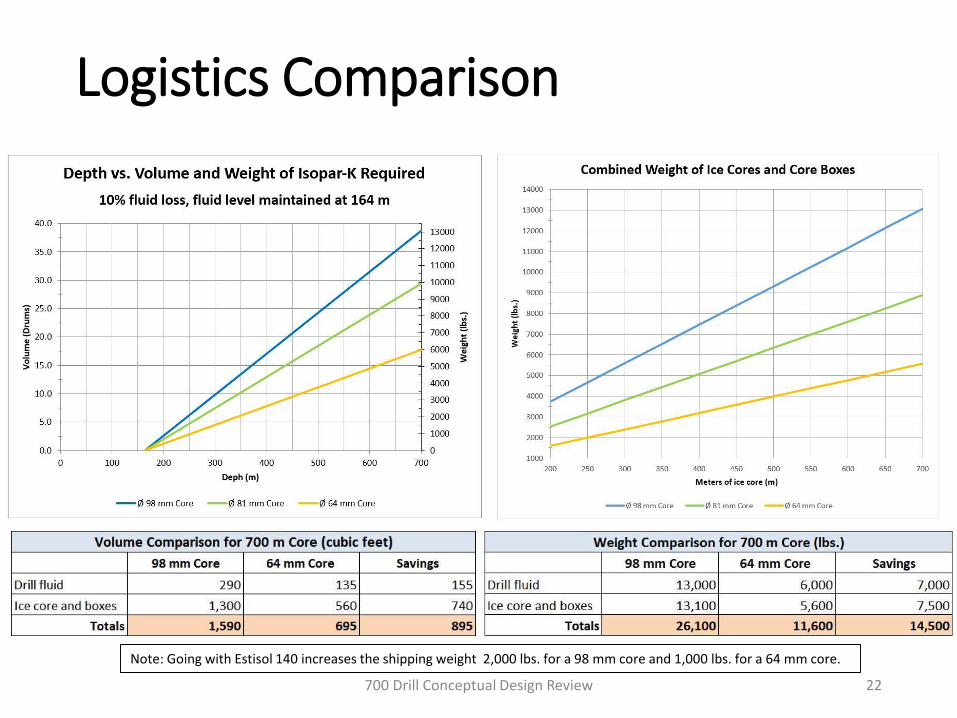
Logistics Comparison
700 Drill Conceptual Design Review 22
Note: Going with Estisol 140 increases the shipping weight 2,000 lbs. for a 98 mm core and 1,000 lbs. for a 64 mm core.

High-Level Equipment List
• Total project cost of equipment and materials is estimated to be $881,000 to $920,000• IDP labor, contractor services and
associated indirect costs are not included
• Completion is expected to take 18 months following approval and funding• Includes fabrication, assembly, testing,
modification (as needed), and field packing
700 Drill Conceptual Design Review 23
Discussion
700 Drill Conceptual Design Review 24