Embed Size (px)
Citation preview
NFI Shore System Spec 18th May 2010 Rev I Page 1 of 35 © NFI Limited 2009
NFI Ltd, 259 Yorktown Rd College Town, Sandhurst,
Berks GU47 0RT UK tel: +44 (0)1276 600200 fax: +44 (0)1276 600161 Email: [email protected]
Web:www.nfi.uk.com
4675 South Windermere Street Englewood, CO 80110 Voice: 303-761-2121 Fax: 303-789-4215 Email: [email protected] Web: www.VantageXP.com
NFI
NFI Shore System Spec 18th May 2010 Rev I Page 2 of 35 © NFI Limited 2009
FOSSL (Fibre Optic Ship Shore Link), Fibre-Optic & ESD (Emergency Shut Down) Electric Shore Side Systems -
General Specification
Contents 1. INTEGRATED ELECTRIC AND FIBREOPTIC SHIP-SHORE LINK
SYSTEMS 2. SHIP SHORE LINK SYSTEM, FIBRE-OPTIC & ELECTRIC SHORE-
SIDE
2.1 General 3.0 SYSTEM COMPONENTS - EQUIPMENT CABINET, CONTROL
ROOM
3.1 Input/Output Module 3.2 Control, Telephone & ESD Module 3.3 Power Supply Module 3.4 Hotphone 3.5 Active Test Module 3.6 Fibre Optic Patch Panel
4.0 SYSTEM COMPONENTS - JETTY
4.1 Fibre Optic Cable 4.2 Fibre Optic Shore Connector 4.3 Combined Fibre Optic and Electric Cable Reel 4.3.1 Fibre Optic Reel 4.3.2 Electric Reel 4.4 Fixed Electric Cable 4.5 Electric Cable Reel 4.6 Vantage Technology (Pyle) Electric Systems
5.0 PNEUMATIC SHORE SIDE SYSTEM 5.1 General Description 5.2 Control Panel Components 5.3 Jetty Components 5.3.1 Jetty Mounted Pneumatic Module
5.3.2 Umbilical Cable & Reel 5.3.3 Nitta Moore/Snaptite Self Sealing Connectors

NFI Shore System Spec 18th May 2010 Rev I Page 3 of 35 © NFI Limited 2009
APPENDIX A1 Telephone Communication Specification A2 ESD Communication Specification A3 Fibre Optic Cable - Optical Characteristics A4 Fibre Optic connector specification A5 Passive Loop back Connector A6 Electric Plug ~ Characteristics A7 Electric Receptacle ~ Characteristics A8 Electric Connector ~ Options A9 Hotphone Specification A10 Combined Cable reel Specification
NFI Shore System Spec 18th May 2010 Rev I Page 4 of 35 © NFI Limited 2009
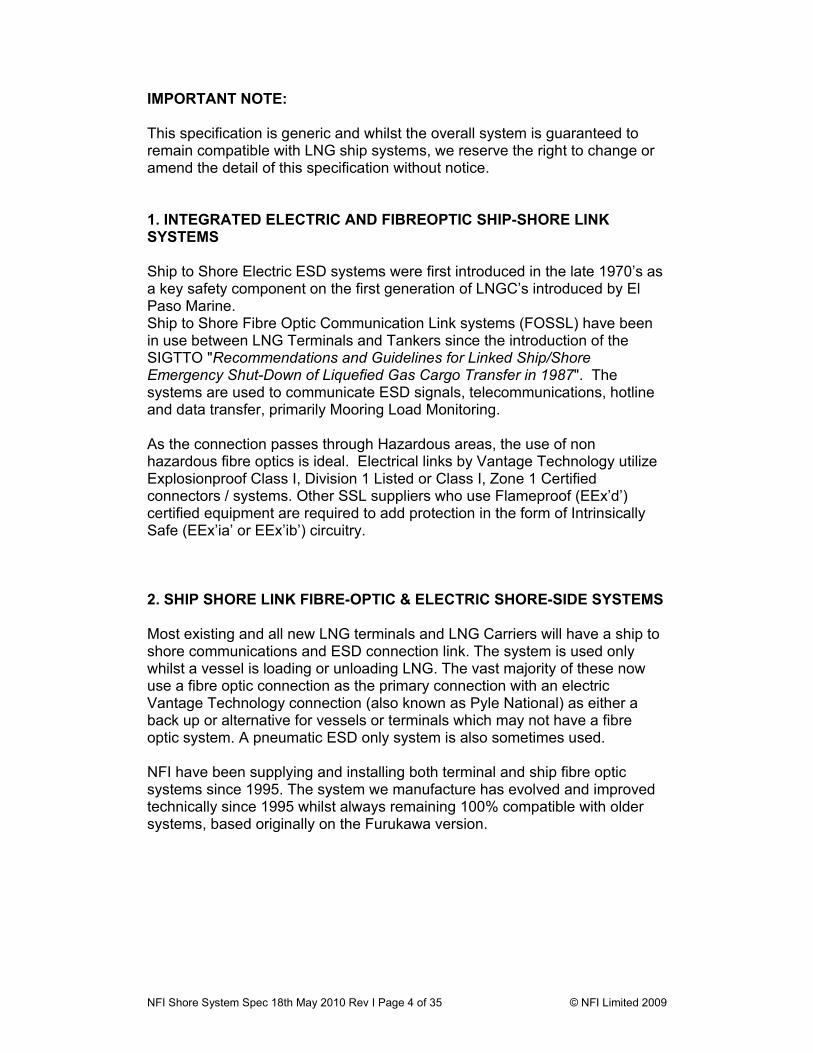
IMPORTANT NOTE: This specification is generic and whilst the overall system is guaranteed to remain compatible with LNG ship systems, we reserve the right to change or amend the detail of this specification without notice. 1. INTEGRATED ELECTRIC AND FIBREOPTIC SHIP-SHORE LINK SYSTEMS Ship to Shore Electric ESD systems were first introduced in the late 1970’s as a key safety component on the first generation of LNGC’s introduced by El Paso Marine. Ship to Shore Fibre Optic Communication Link systems (FOSSL) have been in use between LNG Terminals and Tankers since the introduction of the SIGTTO "Recommendations and Guidelines for Linked Ship/Shore Emergency Shut-Down of Liquefied Gas Cargo Transfer in 1987". The systems are used to communicate ESD signals, telecommunications, hotline and data transfer, primarily Mooring Load Monitoring. As the connection passes through Hazardous areas, the use of non hazardous fibre optics is ideal. Electrical links by Vantage Technology utilize Explosionproof Class I, Division 1 Listed or Class I, Zone 1 Certified connectors / systems. Other SSL suppliers who use Flameproof (EEx’d’) certified equipment are required to add protection in the form of Intrinsically Safe (EEx’ia’ or EEx’ib’) circuitry.
2. SHIP SHORE LINK FIBRE-OPTIC & ELECTRIC SHORE-SIDE SYSTEMS Most existing and all new LNG terminals and LNG Carriers will have a ship to shore communications and ESD connection link. The system is used only whilst a vessel is loading or unloading LNG. The vast majority of these now use a fibre optic connection as the primary connection with an electric Vantage Technology connection (also known as Pyle National) as either a back up or alternative for vessels or terminals which may not have a fibre optic system. A pneumatic ESD only system is also sometimes used. NFI have been supplying and installing both terminal and ship fibre optic systems since 1995. The system we manufacture has evolved and improved technically since 1995 whilst always remaining 100% compatible with older systems, based originally on the Furukawa version.
NFI Shore System Spec 18th May 2010 Rev I Page 5 of 35 © NFI Limited 2009
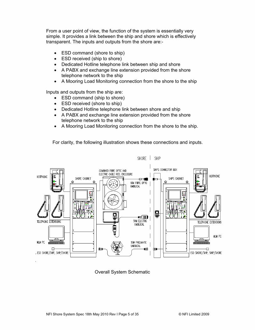
From a user point of view, the function of the system is essentially very simple. It provides a link between the ship and shore which is effectively transparent. The inputs and outputs from the shore are:-
• ESD command (shore to ship) • ESD received (ship to shore) • Dedicated Hotline telephone link between ship and shore • A PABX and exchange line extension provided from the shore
telephone network to the ship • A Mooring Load Monitoring connection from the shore to the ship
Inputs and outputs from the ship are:
• ESD command (ship to shore) • ESD received (shore to ship) • Dedicated Hotline telephone link between shore and ship • A PABX and exchange line extension provided from the shore
telephone network to the ship • A Mooring Load Monitoring connection from the shore to the ship.
For clarity, the following illustration shows these connections and inputs.
Overall System Schematic
NFI Shore System Spec 18th May 2010 Rev I Page 6 of 35 © NFI Limited 2009
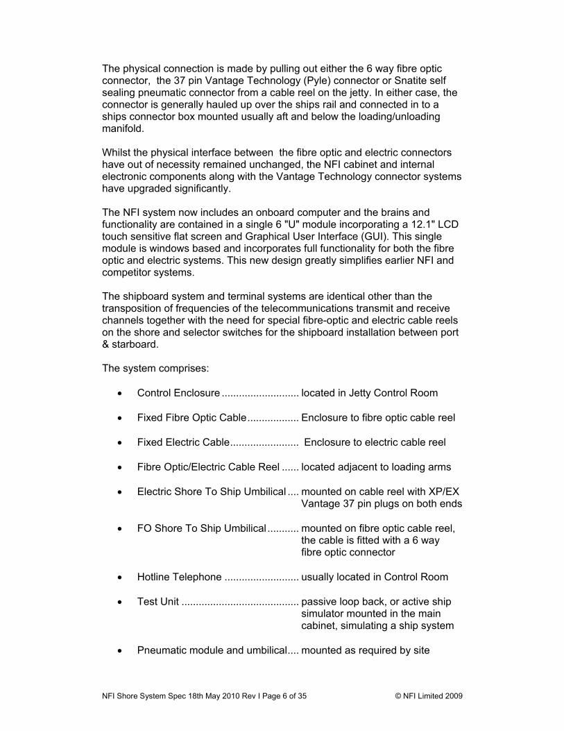
The physical connection is made by pulling out either the 6 way fibre optic connector, the 37 pin Vantage Technology (Pyle) connector or Snatite self sealing pneumatic connector from a cable reel on the jetty. In either case, the connector is generally hauled up over the ships rail and connected in to a ships connector box mounted usually aft and below the loading/unloading manifold. Whilst the physical interface between the fibre optic and electric connectors have out of necessity remained unchanged, the NFI cabinet and internal electronic components along with the Vantage Technology connector systems have upgraded significantly. The NFI system now includes an onboard computer and the brains and functionality are contained in a single 6 "U" module incorporating a 12.1" LCD touch sensitive flat screen and Graphical User Interface (GUI). This single module is windows based and incorporates full functionality for both the fibre optic and electric systems. This new design greatly simplifies earlier NFI and competitor systems. The shipboard system and terminal systems are identical other than the transposition of frequencies of the telecommunications transmit and receive channels together with the need for special fibre-optic and electric cable reels on the shore and selector switches for the shipboard installation between port & starboard. The system comprises:
• Control Enclosure ........................... located in Jetty Control Room • Fixed Fibre Optic Cable.................. Enclosure to fibre optic cable reel
• Fixed Electric Cable........................ Enclosure to electric cable reel
• Fibre Optic/Electric Cable Reel ...... located adjacent to loading arms
• Electric Shore To Ship Umbilical .... mounted on cable reel with XP/EX
Vantage 37 pin plugs on both ends
• FO Shore To Ship Umbilical ........... mounted on fibre optic cable reel, the cable is fitted with a 6 way fibre optic connector
• Hotline Telephone .......................... usually located in Control Room
• Test Unit ......................................... passive loop back, or active ship
simulator mounted in the main cabinet, simulating a ship system
• Pneumatic module and umbilical.... mounted as required by site

NFI Shore System Spec 18th May 2010 Rev I Page 7 of 35 © NFI Limited 2009
Modules contained within the unit are:
• Main input/output PCB • Control Module • Dual Redundant Power Supply Module • Active Test Module • Pneumatic ESD module (optionally within cabinet or on jetty)
The NFI shore system takes up 21 U of 19" rack space and can be fitted within customer specified cabinets. In reality these are normally 800mm wide x 800mm deep x 2100mm high fixed cabinets. A swing frame can be provided should there be limited access to rear of the cabinet. The standard units are IP55 steel enclosures with part glazed front door panel. The system is designed for ship or shore use, and complies with IEC-945 for shipboard equipment. The equipment complies with SIGTTO July 1987 recommendations.
NFI Shore System Spec 18th May 2010 Rev I Page 8 of 35 © NFI Limited 2009
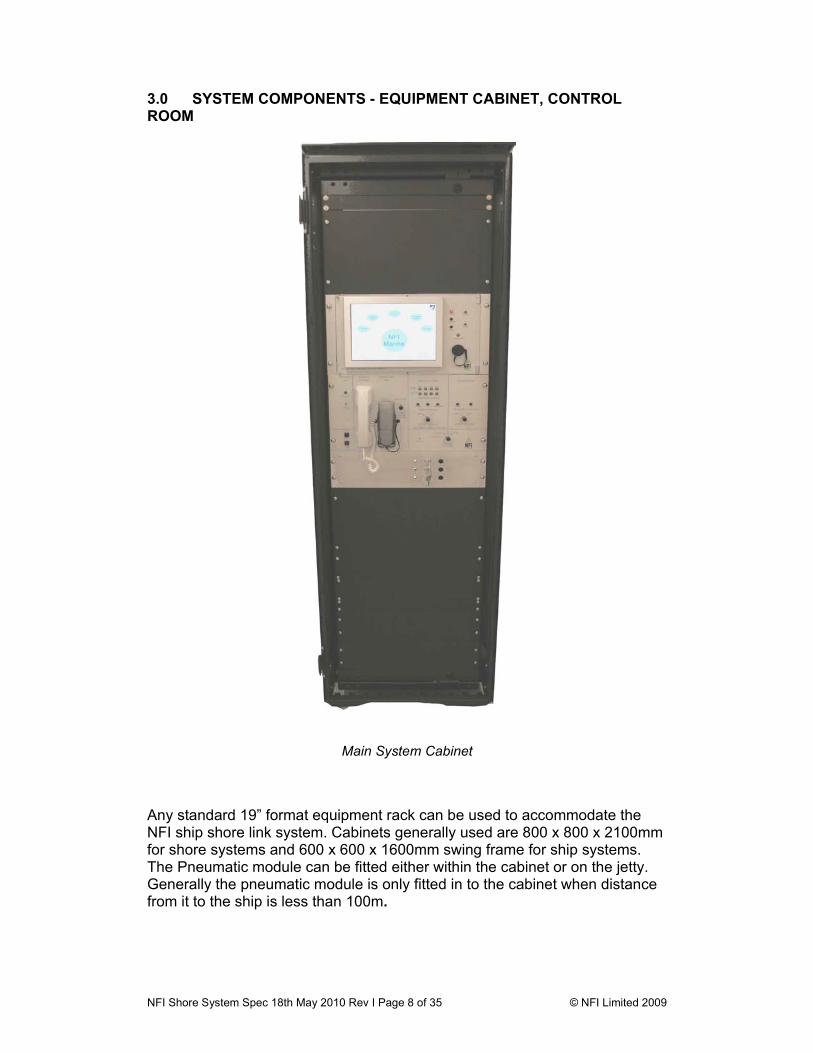
3.0 SYSTEM COMPONENTS - EQUIPMENT CABINET, CONTROL ROOM
Main System Cabinet
Any standard 19” format equipment rack can be used to accommodate the NFI ship shore link system. Cabinets generally used are 800 x 800 x 2100mm for shore systems and 600 x 600 x 1600mm swing frame for ship systems. The Pneumatic module can be fitted either within the cabinet or on the jetty. Generally the pneumatic module is only fitted in to the cabinet when distance from it to the ship is less than 100m.

NFI Shore System Spec 18th May 2010 Rev I Page 9 of 35 © NFI Limited 2009
3.1. Input/Output Module This is a printed circuit board mounted inside and at the bottom of the main equipment cabinet. It incorporates terminal blocks which connect the incoming shore signal wiring (ESD in, ESD out, telephones and hotline, MLM signal input & Common alarm output) to DCS. It also accommodates the fixed cable(s) to the Vantage Technology (Pyle) shore connector(s). Although not required with the Vantage Technology Listed explosionproof connectors - the input/output module also carries IS Zener Barriers and isolators.
3.2 Control, Telephone & ESD Module This is the intelligence of the system and is a 19”, 6U rack module which supports 2-way ESD signalling together with 3 voice and 1 data telephone channels. The unit incorporates a 12.1" LCD touch sensitive screen through which all functionality is controlled, set up & monitored. The screen is used to select either fibre optic or electric mode, and from this selection, the unit will route all channels through the fibre optic cable, in which case the signals are multiplexed, or via the electric system in which case each
Input/Output (I/O) Card
NFI Shore System Spec 18th May 2010 Rev I Page 10 of 35 © NFI Limited 2009
signal is transmitted on a dedicated pair. In the case of the MLM connection, this is an open duplex telephone channel, generally used for a 2 wire modem running at 1200bps. When the electric system is used, the hotphone link to the ship is a simple private line link routed through a single pair of the electric fixed/umbilical cables. As with the hotphone, when in electric mode, the system simply routes the telephone channels through pairs in the electric link to the ship.
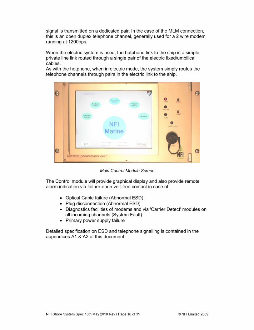
Main Control Module Screen The Control module will provide graphical display and also provide remote alarm indication via failure-open volt-free contact in case of:
• Optical Cable failure (Abnormal ESD) • Plug disconnection (Abnormal ESD) • Diagnostics facilities of modems and via 'Carrier Detect' modules on
all incoming channels (System Fault) • Primary power supply failure
Detailed specification on ESD and telephone signalling is contained in the appendices A1 & A2 of this document.
NFI Shore System Spec 18th May 2010 Rev I Page 11 of 35 © NFI Limited 2009
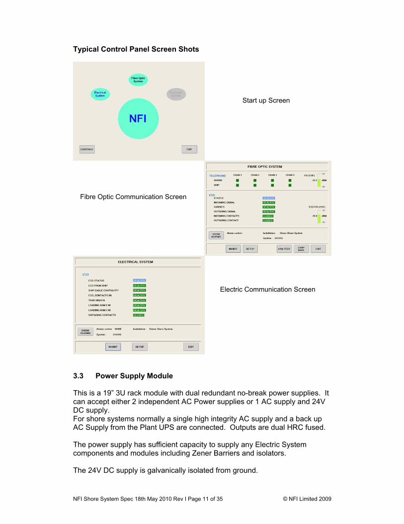
Typical Control Panel Screen Shots
3.3 Power Supply Module This is a 19” 3U rack module with dual redundant no-break power supplies. It can accept either 2 independent AC Power supplies or 1 AC supply and 24V DC supply. For shore systems normally a single high integrity AC supply and a back up AC Supply from the Plant UPS are connected. Outputs are dual HRC fused. The power supply has sufficient capacity to supply any Electric System components and modules including Zener Barriers and isolators. The 24V DC supply is galvanically isolated from ground.
Start up Screen
Fibre Optic Communication Screen
Electric Communication Screen
NFI Shore System Spec 18th May 2010 Rev I Page 12 of 35 © NFI Limited 2009
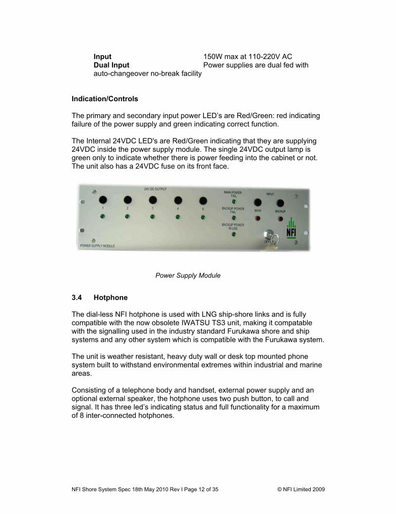
Input 150W max at 110-220V AC Dual Input Power supplies are dual fed with
auto-changeover no-break facility Indication/Controls The primary and secondary input power LED’s are Red/Green: red indicating failure of the power supply and green indicating correct function. The Internal 24VDC LED's are Red/Green indicating that they are supplying 24VDC inside the power supply module. The single 24VDC output lamp is green only to indicate whether there is power feeding into the cabinet or not. The unit also has a 24VDC fuse on its front face.
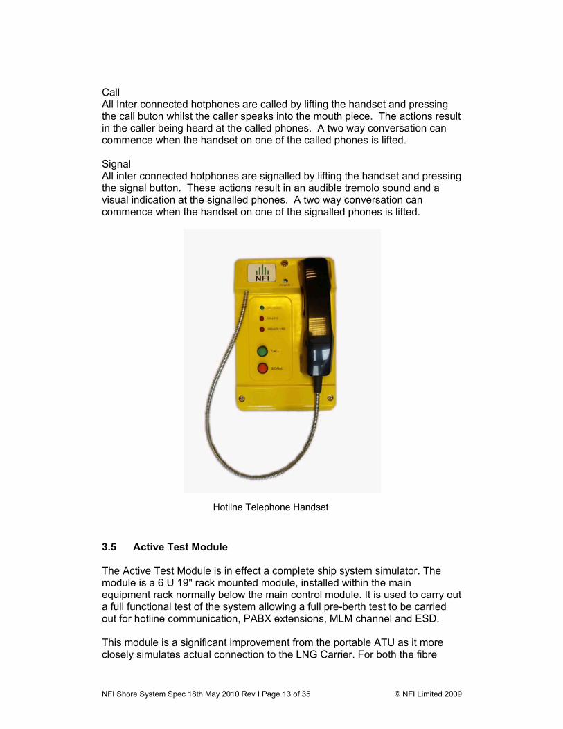
3.4 Hotphone The dial-less NFI hotphone is used with LNG ship-shore links and is fully compatible with the now obsolete IWATSU TS3 unit, making it compatable with the signalling used in the industry standard Furukawa shore and ship systems and any other system which is compatible with the Furukawa system. The unit is weather resistant, heavy duty wall or desk top mounted phone system built to withstand environmental extremes within industrial and marine areas. Consisting of a telephone body and handset, external power supply and an optional external speaker, the hotphone uses two push button, to call and signal. It has three led’s indicating status and full functionality for a maximum of 8 inter-connected hotphones.
Power Supply Module
NFI Shore System Spec 18th May 2010 Rev I Page 13 of 35 © NFI Limited 2009
Call All Inter connected hotphones are called by lifting the handset and pressing the call buton whilst the caller speaks into the mouth piece. The actions result in the caller being heard at the called phones. A two way conversation can commence when the handset on one of the called phones is lifted. Signal All inter connected hotphones are signalled by lifting the handset and pressing the signal button. These actions result in an audible tremolo sound and a visual indication at the signalled phones. A two way conversation can commence when the handset on one of the signalled phones is lifted.
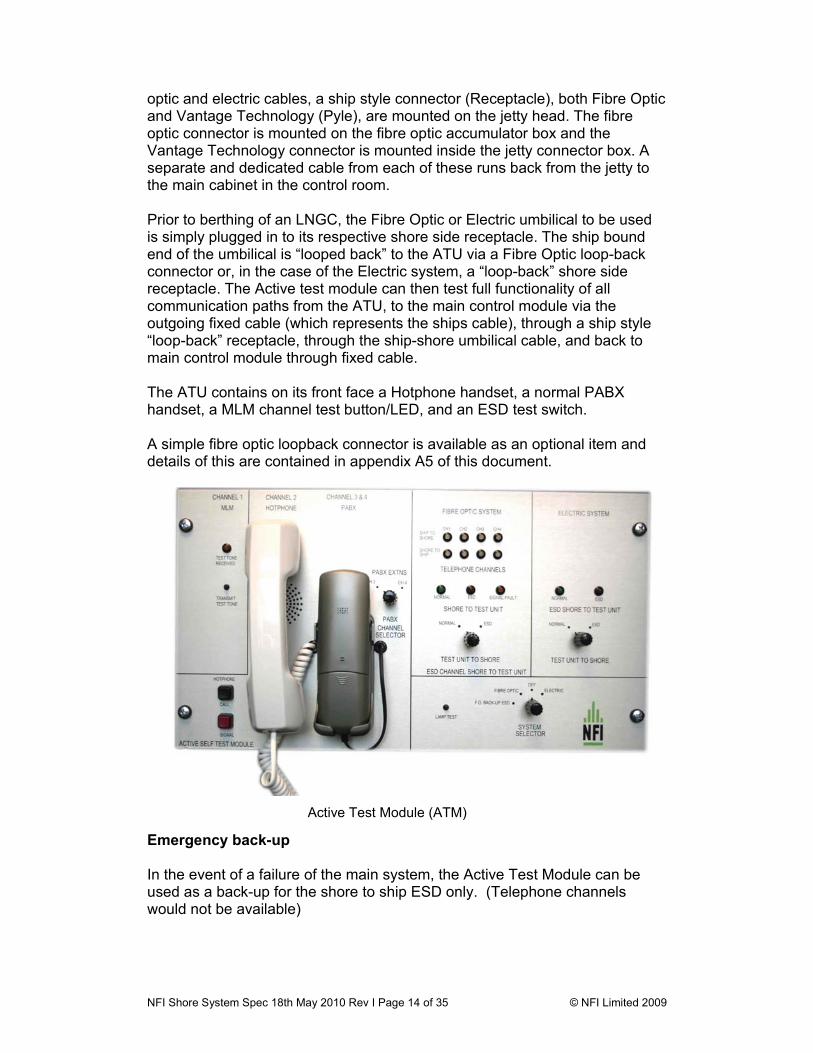
3.5 Active Test Module The Active Test Module is in effect a complete ship system simulator. The module is a 6 U 19" rack mounted module, installed within the main equipment rack normally below the main control module. It is used to carry out a full functional test of the system allowing a full pre-berth test to be carried out for hotline communication, PABX extensions, MLM channel and ESD. This module is a significant improvement from the portable ATU as it more closely simulates actual connection to the LNG Carrier. For both the fibre
Hotline Telephone Handset
NFI Shore System Spec 18th May 2010 Rev I Page 14 of 35 © NFI Limited 2009
optic and electric cables, a ship style connector (Receptacle), both Fibre Optic and Vantage Technology (Pyle), are mounted on the jetty head. The fibre optic connector is mounted on the fibre optic accumulator box and the Vantage Technology connector is mounted inside the jetty connector box. A separate and dedicated cable from each of these runs back from the jetty to the main cabinet in the control room. Prior to berthing of an LNGC, the Fibre Optic or Electric umbilical to be used is simply plugged in to its respective shore side receptacle. The ship bound end of the umbilical is “looped back” to the ATU via a Fibre Optic loop-back connector or, in the case of the Electric system, a “loop-back” shore side receptacle. The Active test module can then test full functionality of all communication paths from the ATU, to the main control module via the outgoing fixed cable (which represents the ships cable), through a ship style “loop-back” receptacle, through the ship-shore umbilical cable, and back to main control module through fixed cable. The ATU contains on its front face a Hotphone handset, a normal PABX handset, a MLM channel test button/LED, and an ESD test switch. A simple fibre optic loopback connector is available as an optional item and details of this are contained in appendix A5 of this document.
Emergency back-up In the event of a failure of the main system, the Active Test Module can be used as a back-up for the shore to ship ESD only. (Telephone channels would not be available)
Active Test Module (ATM)
NFI Shore System Spec 18th May 2010 Rev I Page 15 of 35 © NFI Limited 2009
3.6 Fibre Optic Patch Panel This is installed within the main system cabinet and simply patches between the incoming 6 core fibre optic cable from the jetty to the main Control Module. It is also the termination point for the Active Test Unit return path from the jetty. This unit can accommodate 2 fibre optic cable reels if dual jetties are employed. 4.0 SYSTEM COMPONENTS - JETTY 4.1 Fibre Optic Cable The fixed shore side cable running from the control room to the jetty mounted cable reel is typically 150m long but can be supplied longer if required. The cable is 6 core steel wire braid armoured. Both ends are pre-terminated with Straight Tip (ST) type fibre optic connectors for connection onto the control panel at the control room end and into the connector box on the fibre optic accumulator. The connectors are protected with a rigid PVC sheath during shipment/storage and installation. The umbilical cable is a 6-core flexible type. The material used ensures that the cable pays out straight and does not retain a “memory” of its stored shape. The cable is chemical and fire resistant. It has been tested and proved to operate in a 3-hour fire test. In the event of problems with the fixed cable, the 2 spare cores 5 or 6 can be used in place of a defective core. Similarly, if there are problems with ship or shore - the 2 spare cores 5 or 6 can be used in place of a defective core provided both shore and ship are changed together. For both cable types, each core has a graded index optic fibre core with silicon buffer, Kevlar strain relief and LSZH sheath marked with core number. The overall cable is constructed with a central Fibre Reinforced Plastic strength member with an LSZH compound surround. The 6 fibre-optic cores are grouped together with 6 fillers and covered with an LSZH sheath, fire resistant mica tape and flexible Galvanised Steel Wire Braid armour. A black polyurethane halogen free flame retardant sheath of 2.2mm thickness is used. Sheath is marked with cable type, manufacturer’s name and year of manufacture. Detailed cable specification of the NFI fibre optic cable is contained in appendix A3 of this specification.
NFI Shore System Spec 18th May 2010 Rev I Page 16 of 35 © NFI Limited 2009
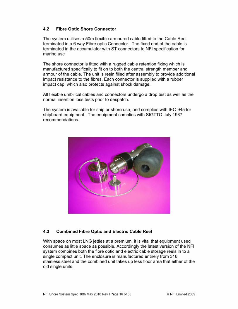
4.2 Fibre Optic Shore Connector The system utilises a 50m flexible armoured cable fitted to the Cable Reel, terminated in a 6 way Fibre optic Connector. The fixed end of the cable is terminated in the accumulator with ST connectors to NFI specification for marine use The shore connector is fitted with a rugged cable retention fixing which is manufactured specifically to fit on to both the central strength member and armour of the cable. The unit is resin filled after assembly to provide additional impact resistance to the fibres. Each connector is supplied with a rubber impact cap, which also protects against shock damage. All flexible umbilical cables and connectors undergo a drop test as well as the normal insertion loss tests prior to despatch. The system is available for ship or shore use, and complies with IEC-945 for shipboard equipment. The equipment complies with SIGTTO July 1987 recommendations.
4.3 Combined Fibre Optic and Electric Cable Reel With space on most LNG jetties at a premium, it is vital that equipment used consumes as little space as possible. Accordingly the latest version of the NFI system combines both the fibre optic and electric cable storage reels in to a single compact unit. The enclosure is manufactured entirely from 316 stainless steel and the combined unit takes up less floor area that either of the old single units.

NFI Shore System Spec 18th May 2010 Rev I Page 17 of 35 © NFI Limited 2009
4.3.1 Fibre Optic Reel This consists of a random lay drum manufactured from 316 stainless steel, housed at the top of the combined enclosure. It incorporates a fibre optic accumulator which allows the cable/connector to be pulled out to the ship without twisting and without being disconnected at the jetty end. This enclosure is designed to protect the cable from direct sunlight and to provide a location for the roller guide when the cable is wound back in.
Combined Fibre Optic/Electric Umbilical Enclosure Shore to ship umbilical cable is fed in to the enclosure through a rectangular letter box opening which has stainless steel cable rollers on all four edges, thus ensuring a smooth entry/exit to the reel. For connection of the shore system to the ships connector box, the combined fibre optic/electric cable reel is located in accordance with industry practice by the installation contractor close to the loading arm base. This reduced size reel can however also be mounted on many suitably equipped gangway access walkway landings. To connect the fibre optic umbilical to an LNGC, the connector is removed from its drop in storage area and hauled on to the ship, normally after a line is passed down from the ship and attached to the stainless steel heaving line attached to the cable.
Fibre optic reel at top Electric reel mounted below
NFI Shore System Spec 18th May 2010 Rev I Page 18 of 35 © NFI Limited 2009
The shore connector, which is connected to the ship, is a straight pull to the ship’s connector box. In practice all ship connection boxes are located just behind and on the main deck below the manifold connection. Simply pulling the cable from the reel deploys the cable. A 316SS basket-weave grip is attached close to the end of the cable to attach a ship’s heaving line to pull the cable on board. In practice sufficient slack must be allowed for ship heave due to ballasting / cargo operations, tidal range and list to ensure the cable is not over tensioned and on board it should be lifted clear of the deck to avoid damage by heavy deck traffic. The cable is re-wound onto the reel by a hand operated winding wheel located on the side of the enclosure. It is not necessary to p[en any part of the enclosure to deploy or recover the fibre optic umbilical. The enclosure has an optional 316 stainless steel ships connector mounted on its front face. This can be used for full functional remote loopback testing of the fibre optic system using the Active Test Module (ATM). The accumulator can be provided with a Hazardous Area enclosure heater EEx ’e’ II T4, together with a flameproof thermostat enabling the unit to operate to –25°C. 4.3.2 Electric Reel The Vantage Electric Umbilical Cable Assembly is also stored in the same combined enclosure. The drum design allows for the bulk of the cable to be stored on the main reel, with a short length of approximately two metres stored securely on the outer edge of the reel, inside the enclosure. This facilitates connection to the Vantage receptacle without the necessity to remove all 35m or 50m from the reel. The reel has a rotation damper to prevent unreeling under gravity and has cable entry access opening at both the front and rear of the unit. This design allows the terminal to first connect to the LNGC receptacle and then to the jetty receptacle. A 316 stainless steel receptacle enclosure is mounted on the rear of cable reel enclosure, close to the top. This accommodates up to two Vantage Technology (Pyle) Receptacles, one for the main shore to ship connection, and the second optional Jetty / Loop-Back Test Receptacle The 37 way Vantage Technology (Pyle) shore side “jetty” receptacle is the interface between the fixed shore cable and the flexible umbilical connected to the ship.
NFI Shore System Spec 18th May 2010 Rev I Page 19 of 35 © NFI Limited 2009
To deploy the electrical umbilical, simply pulling the cable from the reel deploys the cable. A 316SS basket-weave grip is attached close to the end of the cable to attach a ship’s heaving line to pull the cable on board. In practice sufficient slack must be allowed for ship heave due to ballasting / cargo operations, tidal range and list to ensure the cable is not over tensioned and on board it should be lifted clear of the deck to avoid damage by heavy deck traffic. When sufficient cable has been paid out the brake is secured as necessary and the short length of shore cable is connected to the shore receptacle. Full specification of the combined reel is included in appendix A10 of this document. 4.4 Fixed Electric Cable The fixed shore side cable is typically 150 meters from terminal blocks within main control panel to jetty mounted Vantage Technology (Pyle) receptacle(s). This typically 18 AWG (.75 mm²) cable consists of up to 37 conductors or 74 when loop-back active test option is chosen – see section 3.4. The Vantage 37 way AF series receptacle is pre wired and factory sealed: eliminating the need for an Ex gland when attaching fixed cable. If the hazardous area classification is to the Divisional scheme, typical to North America; the Vantage AF series connectors are Class I, Division 1 Listed. If the hazardous area is classified to the zonal scheme, the Vantage AF series connectors are Class I, Zone 1 and ATEX EEx d Certified. With Division 1, Zone 1 & Flameproof (EEx d) protection methods, the fixed cable from main control panel to jetty mounted receptacle need not follow IS routes nor be coloured blue. But where possible IS practice should be followed (spacing from power cables etc) to maintain the integrity of the IS protection provided on specific ship-shore circuitry. 4.5 Vantage Technology (PYLE) Connectors The Electric ESD system relies on the 37 way Vantage Technology (Pyle) AF Series connectors which are CSA / C-US Listed Division 1 explosionproof and ATEX certified EEx’d’ Zone 1 flameproof connectors for ship-shore connection via an umbilical cable…which is typically 50 meters long.. The AF 37-socket jetty and loop-back test receptacles are installed within a stainless steel jetty / loop-back test receptacle box located near or onto the shore / jetty electric cable reel.

NFI Shore System Spec 18th May 2010 Rev I Page 20 of 35 © NFI Limited 2009
The 50m electric umbilical cable is fitted with male Vantage Technology (Pyle) connectors at each end, one end to mate with female shore side / jetty receptacle, the other to be hauled up and connected to the female ship system (port or starboard) receptacle. The Vantage Technology (Pyle) 37-way connectors are machined from 6061-T6 Aluminium and finished by hard anodizing to exceed corrosion resistance requirements per MIL-STD 202, Method 101, Condition D. These same connectors are available in 316 Stainless Steel, but should NEVER be mated with aluminium versions as the plug mates with the receptacles double lead acme threads under a spring loaded condition, which could cause seizing to occur The connector effectively isolates all circuits before the plug and receptacle parts are separated. Although circuit breaking connectors are not recognized within the ATEX certification scheme, Vantage connectors are load break certified under the North American Divisional certification scheme. Note: The Worldwide standard is a female gender receptacle on Shore and Ship. The umbilical interface cable uses male gender plugs at both ends.
NFI Shore System Spec 18th May 2010 Rev I Page 21 of 35 © NFI Limited 2009
5. SHIP SHORE LINK SYSTEM, PNEUMATIC SHORE-SIDE SYSTEM 5.1 General Description As part of the overall SSL system, the pneumatic back-up system can be incorporated into the ESD. Pneumatic systems comprise of Nitta Moore / Snaptite self-sealing connectors installed near the mid-ships manifolds on board. These are connected to the shore installation via an umbilical hose-line. The ship installations are pressurised from the ship’s control air system via a pressure regulator (PRV) set at about 0.25 bar above the set point of the shore system and a restricting needle valve The shore installations may be un-pressurised or may be similarly pressurised. The shore is provided with a pressure switch with pressure setting fixed and the ship is usually fitted with pressure switch with variable setting to match the shore. Similarly the pressure regulator is adjusted on board to about 0.25 bar above the set point dictated by shore. When the system is depressurised, both ship and shore pressure switches trip external circuits in accordance with SIGTTO guidelines. Depressurisation may be initiated by:
• An electrical trip which acts on the ship or shore fail-safe solenoid valve • Fusible plugs installed in pneumatic branches near valves and flanges
vulnerable to leakage and fire (methane flames emit low levels of visible light)
• A manual pneumatic trip dumping air from the system • Rupture of the umbilical hose in the event of a breakaway or cryogenic
spill. The pneumatic module can be located within the System Enclosure provided the distance to the jetty connector is 50 meters or less. If necessary the equipment is located near the jetty in a safe area. The Nitta-Moore connector is located near or within the Jetty Receptacle Enclosure. 5.2 Control Panel Components Pneumatic Module This is a 3U high 19” module mounted in the base of the System Enclosure. It carries the pneumatic components within it. A digital pressure indicator reads line pressure and LEDS indicate
• System Healthy • System Trip • Solenoid Valve Energised
NFI Shore System Spec 18th May 2010 Rev I Page 22 of 35 © NFI Limited 2009
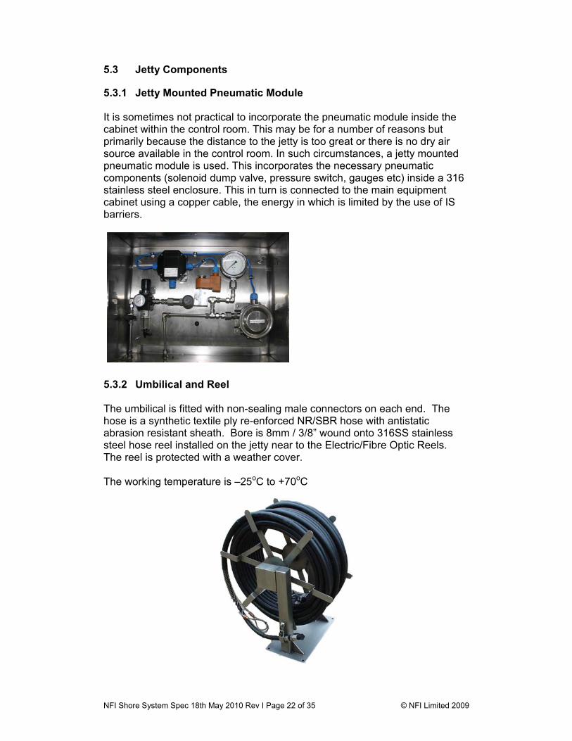
5.3 Jetty Components 5.3.1 Jetty Mounted Pneumatic Module It is sometimes not practical to incorporate the pneumatic module inside the cabinet within the control room. This may be for a number of reasons but primarily because the distance to the jetty is too great or there is no dry air source available in the control room. In such circumstances, a jetty mounted pneumatic module is used. This incorporates the necessary pneumatic components (solenoid dump valve, pressure switch, gauges etc) inside a 316 stainless steel enclosure. This in turn is connected to the main equipment cabinet using a copper cable, the energy in which is limited by the use of IS barriers.
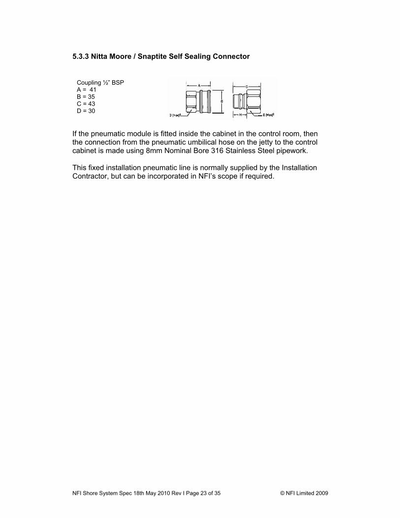
5.3.2 Umbilical and Reel The umbilical is fitted with non-sealing male connectors on each end. The hose is a synthetic textile ply re-enforced NR/SBR hose with antistatic abrasion resistant sheath. Bore is 8mm / 3/8” wound onto 316SS stainless steel hose reel installed on the jetty near to the Electric/Fibre Optic Reels. The reel is protected with a weather cover. The working temperature is –25oC to +70oC
NFI Shore System Spec 18th May 2010 Rev I Page 23 of 35 © NFI Limited 2009
5.3.3 Nitta Moore / Snaptite Self Sealing Connector
If the pneumatic module is fitted inside the cabinet in the control room, then the connection from the pneumatic umbilical hose on the jetty to the control cabinet is made using 8mm Nominal Bore 316 Stainless Steel pipework. This fixed installation pneumatic line is normally supplied by the Installation Contractor, but can be incorporated in NFI’s scope if required.
Coupling ½” BSP A = 41 B = 35 C = 43 D = 30

NFI Shore System Spec 18th May 2010 Rev I Page 24 of 35 © NFI Limited 2009
APPENDIX A1 Telephone Communication Specification Transmission Scheme Modem 2 wire full duplex voice-band carrier frequency with Both Side Band (BSB) Multiplex Method Frequency Division Multiplex modulation Modulation Scheme Frequency Shift Method Carrier 2.6 kHz Frequency Allocation Channel Ship-Shore Receive carriers Ship-Shore Transmit carriers 1 Data Channel 18 kHz 78 kHz 2 Hot line phone 30 kHz 90 kHz 3 Public phone 42 kHz 102 kHz 4 Internal phone 54 kHz 114 kHz
Transmission Method 1 Tx and 1 Rx electrical/Optical Modem Optical Wavelength 0.85µm+/- 0.03µm Light source LED Detector PIN photo-detector Connector ST type Sound frequency bandwidth 0.3-3.4 kHz (3/5 in CCITT or less) Sound distortion rate 10% or less for 800 Hz standard level transmission Signal>Noise, cross talk better than 35 dB Tx power 0.015 mW min, > -18 dBm Rx sensitivity 650 nW min < -32 dBm Level and Impedance, sound Input 0 dBm 600Ω balanced Output -8* dBm 600Ω balanced (*Ch 1 is -15 dBm) Level and Impedance, line Input 1V pp 75Ω unbalanced Output 1V pp 75Ω unbalanced Off-hook signalling Ch 2 - Ch 4 AGC Active AGC with +2 dBm control in response to 10 dB optic carrier variation of +5..-10 dBm reduced to +2..-3 dBm on audio side
Carrier Detect The LCD Display shows status of all signals, abnormal indication via 'Carrier Detect' modules on all incoming channels.
During normal operation the carrier indicators on the GUI display the status of each telephone channel received from the ship.
NFI Shore System Spec 18th May 2010 Rev I Page 25 of 35 © NFI Limited 2009
A2 ESD Communication Specification Incorporated within the 19" 6U control module with dedicated Transmit/Receive Electronic>Optical transducers. Signals are provided by tone for normal safe mode and normal ESD mode. It also incorporates a fail-safe operation function. Transmission Scheme Audio tone Frequency shift keying method Normal safe mode Rx/Tx 10 kHz ± 10% Normal ESD Rx/Tx 5 kHz ± 10% Abnormal ESD received frequencies other than above Optical Wavelength 0.85µm+/- 0.03µm Light source LED Detector PIN photo-detector Connector ST type Tx power 0.015 mW min, > -18 dBm Rx sensitivity 650 nW min < -32 dBm Optical Wavelength 0.85µm+/- 0.03µm, Outputs Voltage opto-coupled outputs and two independent volt-free contacts, Normally Open, Closed for healthy operation, Open for ESD. Contacts Rated at 240V-3A, for connection into the shipboard ESD system. No operator actions are required during system operation between the ship & shore. For transmission of the ESD signal over the electric system the IS Barriers used are MTL/Pepperl & Fuchs items, which carry DEMA/BASEEFA certification. They are mounted on the I/O PCB at the bottom of the main cabinet. Wiring follows IS practice although this is not a full IS primary protection installation As an added safety feature Vantage Technology electrical connectors are certified to make and break up to 6.5 AMPS @ 250 VAC under load – the use of IS barriers is a redundant safety feature.
NFI Shore System Spec 18th May 2010 Rev I Page 26 of 35 © NFI Limited 2009
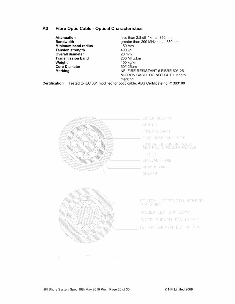
A3 Fibre Optic Cable - Optical Characteristics
Attenuation less than 2.8 dB / km at 850 nm Bandwidth greater than 200 MHz.km at 850 nm
Minimum bend radius 150 mm Tension strength 400 kg Overall diameter 20 mm Transmission band 200 MHz.km Weight 450 kg/km
Core Diameter 50/125µm Marking NFI FIRE RESISTANT 6 FIBRE 50/125
MICRON CABLE DO NOT CUT + length marking
Certification Tested to IEC 331 modified for optic cable. ABS Certificate no P1363100
NFI Shore System Spec 18th May 2010 Rev I Page 27 of 35 © NFI Limited 2009
A4 Fibre Optic connector specification
Material: Body 316 Stainless Steel Material: Sleeves Phosphor Bronze Material: Protection Cap Naval Bronze with Hard Rubber impact cap Optical coupling method Full ceramic ferrule FC single mode type Signal arrangement Ferrule no: 1
2 3 4 5 6
Tel channel Tel channel ESD channel ESD channel Spare Spare
Ship-Shore Shore-Ship Ship-Shore Shore-Ship
Protection Mounted within IP56 enclosure with hydraulic “0” ring seal on cap
Connection loss <1dB insertion loss Tensile strength >1000N Certification Vibration
Mating Durability Cable Retention
EN61300 - 2.1 EN61300 - 2.2 EN61300 - 2.4 EN61300 - 3.1
Test House TUV Certifying authority DNV
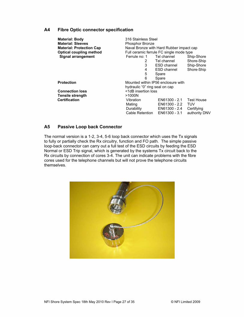
A5 Passive Loop back Connector The normal version is a 1-2, 3-4, 5-6 loop back connector which uses the Tx signals to fully or partially check the Rx circuitry, function and FO path. The simple passive loop-back connector can carry out a full test of the ESD circuits by feeding the ESD Normal or ESD Trip signal, which is generated by the systems Tx circuit back to the Rx circuits by connection of cores 3-4. The unit can indicate problems with the fibre cores used for the telephone channels but will not prove the telephone circuits themselves.
NFI Shore System Spec 18th May 2010 Rev I Page 28 of 35 © NFI Limited 2009
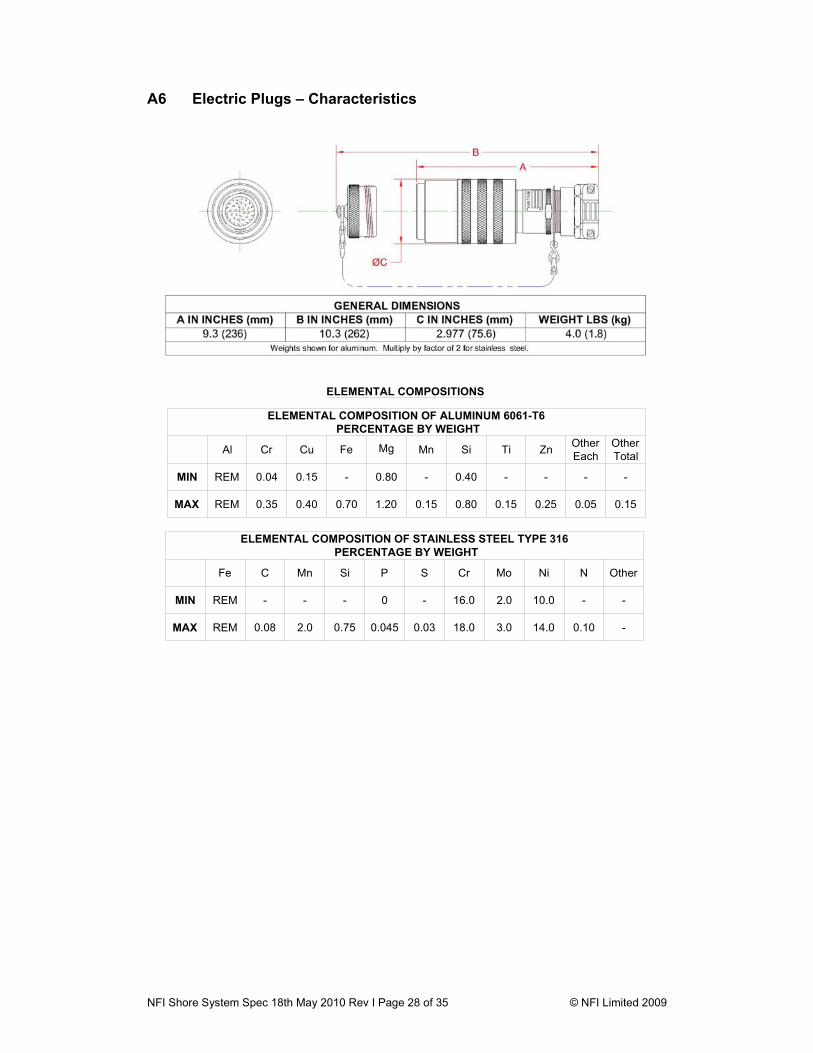
A6 Electric Plugs – Characteristics
Fe
REM
C Mn
- -
Si P
0 -
S Cr
16.0 2.0
Mo Ni
10.0 -
N Other
--
0.08 -0.1014.03.018.00.030.0450.752.0REM
MIN
MAX
ELEMENTAL COMPOSITION OF STAINLESS STEEL TYPE 316 PERCENTAGE BY WEIGHT
ELEMENTAL COMPOSITIONS
ELEMENTAL COMPOSITION OF ALUMINUM 6061-T6 PERCENTAGE BY WEIGHT
MAX
MIN
REM 0.40 0.70 1.20 0.15 0.80 0.15 0.25 0.05 0.150.35
0.04 -
OtherTotal
OtherEach
--
ZnTi
-0.40
SiMn
-0.80
MgFe
-0.15
CuCr
REM
Al

NFI Shore System Spec 18th May 2010 Rev I Page 29 of 35 © NFI Limited 2009
OperationThe plug features a quick make and break design. To engage, align plug to receptacle and turn coupling
sleeve clockwise. Plug will be injected automatically & close circuit. Continue turning coupling sleeve to solid toprovide environmental seal. To disengage, rotate coupling sleeve counter (c.c.w.) clockwise. Plug will ejectautomatically. Continue turning coupling sleeve to extract the plug. Caution: Do not interfere with cable housing.Note: In reverse service applications, for safety from shock hazard, the plug cover must be threaded onto plugwhen plug not in use.
MaterialsAF Series, Copper free (0.15-0.40% by weight) wrought Aluminum 6061-T6 with hardcoating per
Mil-A-8625 Type III, black finish.SF Series, Stainless Steel Type 316.
MaintenancePeriodic maintenance consists of inspection for termination integrity and contamination. When conditions
require, lubricate coupling threads with silicone oil, Vantage Part Number VT-9400-21D.
Ratings and Certifications
C US
0344 II 2 G D, EEx d IIC T6, KEMA 04ATEX2179 X; -20°C = Ta = +50°C; IP 66/67, T70°C.For Standard and Reverse Service, 50/60/400 Hz, 250 Vac / 125 Vdc.
CSA International, U.S. and Canadian Standards: Class I, Division 1, Groups B, C & D and Class II,Division 1, Groups F & G for Standard and Reverse Service, 60 Hz, 250 Vac. Select inserts are ratedat 480 Vac non-circuit breaking.
NFI Shore System Spec 18th May 2010 Rev I Page 30 of 35 © NFI Limited 2009
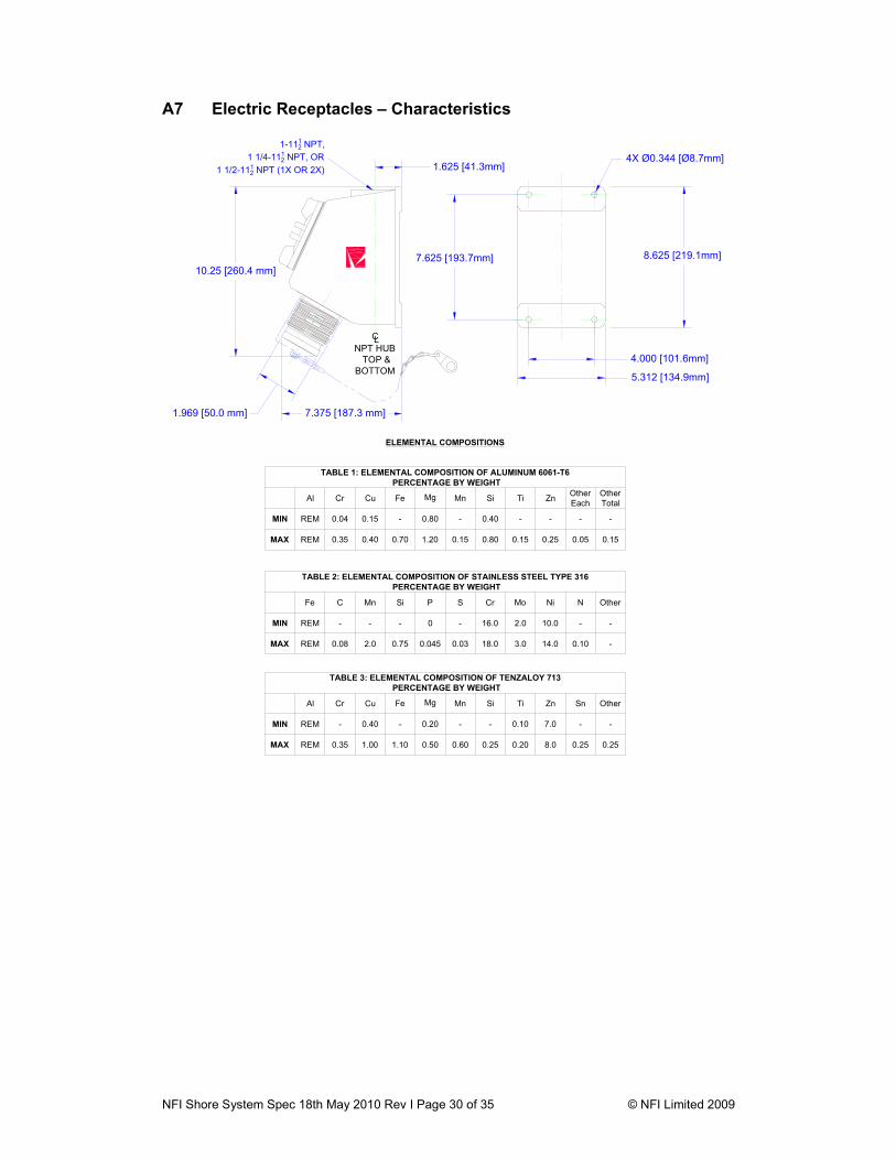
A7 Electric Receptacles – Characteristics
10.25 [260.4 mm]
7.375 [187.3 mm]1.969 [50.0 mm]
LC
1-1112 NPT,
1 1/4-1112 NPT, OR
1 1/2-1112 NPT (1X OR 2X) 1.625 [41.3mm]
8.625 [219.1mm]
4X Ø0.344 [Ø8.7mm]
4.000 [101.6mm]NPT HUB
TOP &BOTTOM
7.625 [193.7mm]
5.312 [134.9mm]
Fe
REM
C Mn
- -
Si P
0 -
S Cr
16.0 2.0
Mo Ni
10.0 -
N Other
--
0.08 -0.1014.03.018.00.030.0450.752.0REM
MIN
MAX
TABLE 2: ELEMENTAL COMPOSITION OF STAINLESS STEEL TYPE 316 PERCENTAGE BY WEIGHT
TABLE 3: ELEMENTAL COMPOSITION OF TENZALOY 713 PERCENTAGE BY WEIGHT
MAX
MIN
REM 1.00 1.10 0.50 0.60 0.25 0.20 8.0 0.250.35
-
Sn
-7.0
ZnTi
0.10-
SiMn
-0.20
MgFe
-0.40
CuCr
REM
Al Other
-
0.25
ELEMENTAL COMPOSITIONS
TABLE 1: ELEMENTAL COMPOSITION OF ALUMINUM 6061-T6 PERCENTAGE BY WEIGHT
MAX
MIN
REM 0.40 0.70 1.20 0.15 0.80 0.15 0.25 0.05 0.150.35
0.04 -
OtherTotal
OtherEach
--
ZnTi
-0.40
SiMn
-0.80
MgFe
-0.15
CuCr
REM
Al

NFI Shore System Spec 18th May 2010 Rev I Page 31 of 35 © NFI Limited 2009
OperationReceptacles are mated to plugs that feature a quick make and break design. To engage, align plug to receptacle and turn
coupling sleeve clockwise. Plug will be injected automatically & close circuit. Continue turning coupling sleeve to solid to provideenvironmental seal. To disengage, rotate coupling sleeve c.c.w. (counterclockwise). Plug will eject automatically. Continueturning coupling sleeve to extract the plug. Caution: Do not interfere with cable housing. To prevent shock hazard the receptaclecover must be threaded onto receptacle when receptacle is not in use.
Materials (See Tables 1, 2 and 3 above for Material Composition data)AF Series, Wrought Aluminum 6061-T6, copper-free, with Hardcoating per Mil-A-8625 Type III, black finish.SF Series, Stainless Steel Type 316.Junction box enclosures, Tenzaloy 713, with a black powder coat finish.
AssemblyReceptacles are designed for field termination. Wire leads can be spliced or landed to terminals. No special tools are
required.
MaintenancePeriodic maintenance consists of inspection for termination integrity and contamination. When conditions require, lubricate
coupling threads with silicone oil, Vantage Part Number VT-9400-21D.
C US
0344 II 2 G D, EEx d IIC T6, KEMA 04ATEX2179 X; -20°C = Ta = +50°C; IP 66/67, T70°C.For Standard and Reverse Service, 50/60/400 Hz, 250 Vac / 125 Vdc.
Ratings and Certifications
CSA International, U.S. and Canadian Standards: Class I, Division 1, Groups B, C & D and Class II, Division 1, GroupsF & G for Standard and Reverse Service, 60 Hz, 250 Vac. Select inserts are rated at 480 Vac non-circuit breaking.
NFI Shore System Spec 18th May 2010 Rev I Page 32 of 35 © NFI Limited 2009
A8 Electric Connector – Options
Vantage Technology has a 35 year history with the LNG industry starting in the mid 70’s when, as the Pyle National Group, we collaborated with El Paso Marine to establish the first ESD / Emergency Shut Down system. This system was soon (1977-78) installed on the following “first generation” LNG carriers. El Paso LNGC Builder / Location Columbia Cove Point Savannah
Avondale Shipyards Louisiana, USA
Consolidated Paul Kayser Sonatrach
Chantiers de France Dunkirk, France
Arzen Howard Boyd Southern
Newport News Ship Virginia, USA
In 1997 Vantage Technology LLC acquired the Pyle National Group and set out to perfect the Electric ESD Link as the standard of safety.
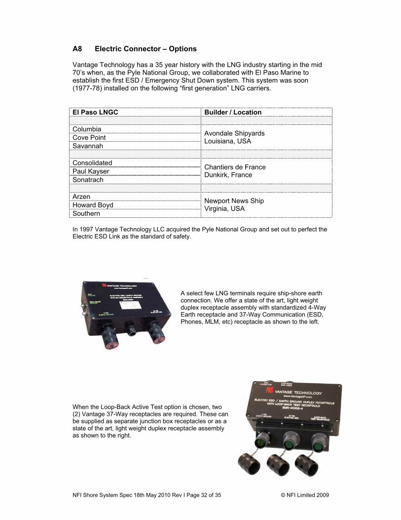
A select few LNG terminals require ship-shore earth connection. We offer a state of the art, light weight duplex receptacle assembly with standardized 4-Way Earth receptacle and 37-Way Communication (ESD, Phones, MLM, etc) receptacle as shown to the left.
When the Loop-Back Active Test option is chosen, two (2) Vantage 37-Way receptacles are required. These can be supplied as separate junction box receptacles or as a state of the art, light weight duplex receptacle assembly as shown to the right.
NFI Shore System Spec 18th May 2010 Rev I Page 33 of 35 © NFI Limited 2009
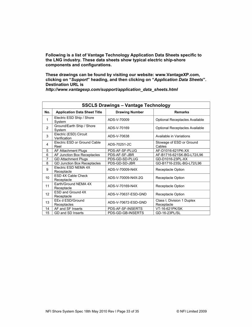
Following is a list of Vantage Technology Application Data Sheets specific to the LNG industry. These data sheets show typical electric ship-shore components and configurations. These drawings can be found by visiting our website: www.VantageXP.com, clicking on “Support” heading, and then clicking on “Application Data Sheets”. Destination URL is http://www.vantagexp.com/support/application_data_sheets.html
SSCLS Drawings – Vantage Technology No. Application Data Sheet Title Drawing Number Remarks
1 Electric ESD Ship / Shore System ADS-V-70009 Optional Receptacles Available
2 Ground/Earth Ship / Shore System ADS-V-70169 Optional Receptacles Available
3 Electric (ESD) Circuit Verification ADS-V-70638 Available in Variations
4 Electric ESD or Ground Cable Reel ADS-70251-2C Stowage of ESD or Ground
Cables 5 AF Attachment Plugs PDS-AF-SF-PLUG AF-D1016-621PK-XX 6 AF Junction Box Receptacles PDS-AF-SF-JBR AF-B1716-621SK-BG-L72/L96 7 GD Attachment Plugs PDS-GD-SD-PLUG GD-D1016-23PL-XX 8 GD Junction Box Receptacles PDS-GD-SD-JBR GD-B1716-23SL-BG-L72/L96
9 Electric ESD NEMA 4X Receptacle ADS-V-70009-N4X Receptacle Option
10 ESD 4X Cable Check Receptacle ADS-V-70009-N4X-2G Receptacle Option
11 Earth/Ground NEMA 4X Receptacle ADS-V-70169-N4X Receptacle Option
12 ESD and Ground 4X Receptacle ADS-V-70637-ESD-GND Receptacle Option
13 EEx d ESD/Ground Receptacles ADS-V-70672-ESD-GND Class I, Division 1 Duplex
Receptacle 14 AF and SF Inserts PDS-AF-SF-INSERTS VT-16-621PK/SK 15 GD and SD Inserts PDS-GD-GB-INSERTS GD-16-23PL/SL
NFI Shore System Spec 18th May 2010 Rev I Page 34 of 35 © NFI Limited 2009
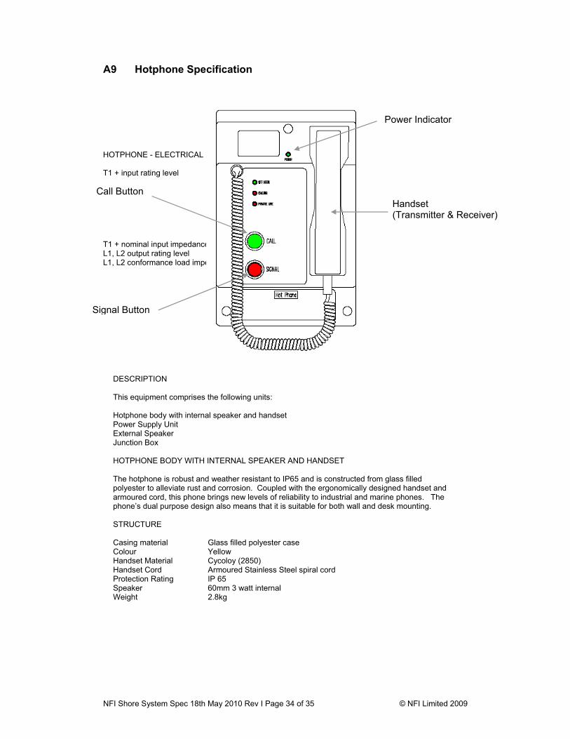
A9 Hotphone Specification
HOTPHONE - ELECTRICAL SPECIFICATIONS T1 + input rating level -55dBm
T1 + nominal input impedance 55 ohm L1, L2 output rating level 0 dBm (+3 dB to –6dB) L1, L2 conformance load impedance 600 ohms
Power Indicator
Handset (Transmitter & Receiver)
Call Button
Signal Button
DESCRIPTION This equipment comprises the following units: Hotphone body with internal speaker and handset Power Supply Unit External Speaker Junction Box HOTPHONE BODY WITH INTERNAL SPEAKER AND HANDSET The hotphone is robust and weather resistant to IP65 and is constructed from glass filled polyester to alleviate rust and corrosion. Coupled with the ergonomically designed handset and armoured cord, this phone brings new levels of reliability to industrial and marine phones. The phone’s dual purpose design also means that it is suitable for both wall and desk mounting. STRUCTURE Casing material Glass filled polyester case Colour Yellow Handset Material Cycoloy (2850) Handset Cord Armoured Stainless Steel spiral cord Protection Rating IP 65 Speaker 60mm 3 watt internal Weight 2.8kg
NFI Shore System Spec 18th May 2010 Rev I Page 35 of 35 © NFI Limited 2009
Distortion 1% at rated output (1 Khz) Frequency Range 300 Hz to 3400 Hz + 0dB –3dB (BS6317:1982 Part 13, Class A) S/N ratio 50 dB min (BS6317:1982 Part 13, Class A) Sidetone attenuation 20 dBm min Control of calling DC 3V min applied to L1 L2 Signal tone transmission Tremolo of 700-1000 Hz Line length Up to 10km Internal Speaker 3 watt HOTPHONE - GENERAL SPECIFICATIONS Operating Temperature -20°C to +55°C Humidity Up to 95% (non condensing) Weight 2.8kg EMC compliant FCC Class B and EN55022, IEC 945-1 for Marine use POWER SUPPLY UNIT- ELECTRICAL SPECIFICATIONS Power Supply Input 85-264 V AC input Input Current 0.5 A rms AC @ 230V Frequency 45-440 Hz Output voltage 24 V DC Output voltage range +/- 5% at full load Output current 3 amp Max. Output ripple 50mV max (peak to peak) DC - 100 MHz POWER SUPPLY UNIT - GENERAL SPECIFICATIONS Temperature range -20°C to +55°C Humidity Up to 95% (non condensing) Temperature range -20°C to +70°C Dielectric strength 1000 V AC (input to case) Insulation resistance 10 MΩ or more at 1000 V AC Weight 0.5 kg EMC compliant FCC Class B and EN55022