Embed Size (px)
Citation preview
'J
fRITZ ENGINEERING LABORATORY·LEHIGH UNIVERSITY
BETHLEHEM. PENNSYLVANIA
fot.entia,l j'Flow in 90° !gen~$
b~ Ielectt'ica.t Ana.log~ .
.b~
ll.ci. N.Jltu~tb~.
A reportpresented to the Department of Civil Engineering
Lehigh University ..for credit in C.E. 421: Hydraulic Laboratory Practice
(Project No . 257) in partial fulfilment for the Degree ofMaster of Science in Civil Engineering
L~HIGH UNIVERSITYMay 1956
LEHIGH UNIVERSITYDepartment of Civil Engineering
May 1956
STATEMENT OF EQUIVALENT EXPENSES
Project 257
C.E. 421: Hydraulic Laboratory Practice
Wages and Salaries:
l. Mr. Oosztonyi, Mechanic, Hydraulic Laboratory $ 50.00(Salary_ Value)
2. Mr. Taylor (Instrumentation) and assistants $ 100.00(Salary Value)
3. Supervision by Professor M.B. MCPherson $ 200.00(Salary Value)
4. Number of hours worked by me-150 hours @ $1.50/hr. $ 225.00
Expenses:
5. First elbow (short radius)-cost of material6. Second elbow (long radius)-cost of material7. Rectangular plastic model-cost of material8. Cost of cutting the above models9. Cost of insulating materials10. Stationery, litho, ozalids, typing, binding, etc.11. Photograph
Cost of Equipment:
12. Fluid mechanics laboratory equipment13. Fritz laboratory equipment14. Value of my Gotshall Scholarship of Lehigh University
for the period
Total costt9 Lehigh University exclusive ofscholarship (Items 1, 2, 3, 5, 6, 7, 8, 9, 11)~quivalent project cost-exclusive of overhead(Items 4, 10, 11, 12, 13, 14)
Note:
Item Nos. 1, 5, 6, 7, 8, 9 and 11: - Paid throughAccount 354-L Student instruction budgetItem No. 10: - Paid by me.
D. S. N. Murthy
$ 5.00$ 15.00$ 5.00$ 35.00$ 5.00$ 20.00$ 10.00
$ 150.00$ 200.00
$ 180.00
$ 425.00
$ 775.00
POTENTIAL.FLOWIN90o BENDS BY ELECTRICAL ANALOGY
by
D. S. N. "Murthy
C.E.421: Hydraulic Laboratory Practice
Fritz Laboratory Project No. 257
LEHIGH UNIVERSITYMay 1956
. ~',
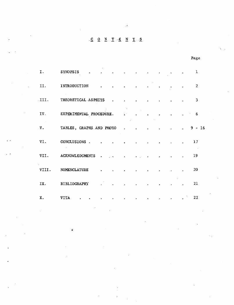
CON TENTS
Page
I. SYNOPSIS 1
II. INTRODUCTION 2
III. THEORETICAL ,ASPECTS 3
IV. EXPERlMENTA,L PROCEDURE. 6
V. TABLES, GRAPHS, AND PHOTO 9 - 16
VI. CONCLUSIONS . 17
VII. ACKNOWLEDGMENTS 19
VIII. NOMENCLATURE 20
IX. BIBLIOGRAPH): 21
X. VITA 22
-1
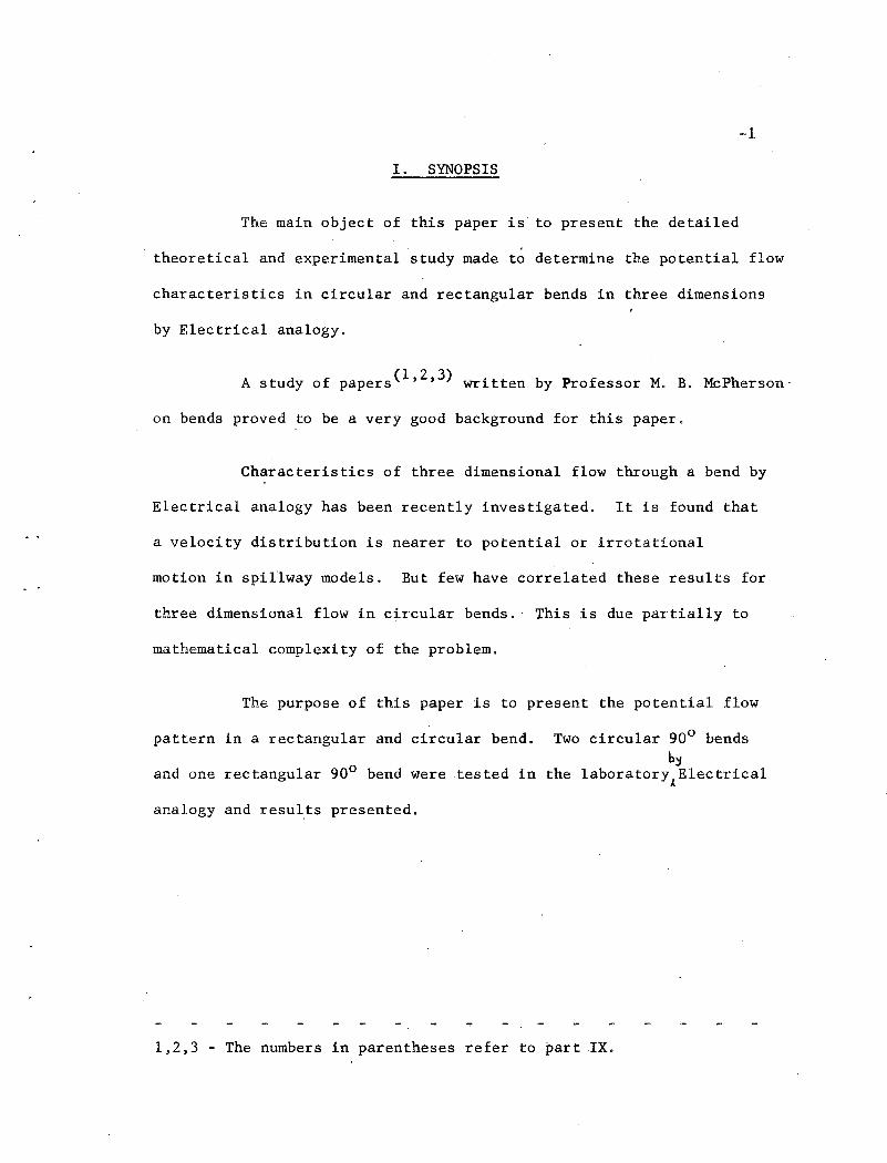
I. SYNOPSIS
The main object of this paper is to present the detailed
theoretical and experimental study made to determine the potential flow
characteristics in circular and rectangular bends in three dimensions
by Electrical analogy.
A study of papers(1,2,3) written by Professor M. B. McPherson-
on bends proved to be a very good background for this paper.
Characteristics of three dimensional flow through a bend by
Electrical analogy has been recently investigated. It is found that
a velocity distribution is nearer to potential or irrotationa1
motion in spillway models. But few have correlated these results for
three dimensional flow in circular bends. This is due partially to
mathematical complexity of the problem.
The purpose of this paper is to present the potential flow
pattern in a rectangular and circular bend.
and one rectangular 900 bend were tested in
analogy and results presented.
Two circular 90 0 bendsb~
the 1aboratorYAE1ectrica1
1,2,3 The numbers in parentheses refer to part IX.
-2
II. INTRODUCTION
Potential flow or irrotational flow in three dimensions was
investigated by t~e,applicationof the Electrical analogy to
hydrodynamic problems in three dimensions by Hubbard and ~ing .atIowa
Institute of Hydraulic Research(4) 0 But the method now presented
differs slightly from the above •
. The present method, a variation of the "electrolytic-tank
method", consists in establishing within the electrolytic conductor
a potential field similar to that of its fluid prototype by applying a
voltage across the conductor, between the zones representing the
entrance and exit of the fluid in the system. The potential pattern
may be obtained by knowing the voltages between two constant distance
(say 1/2") electrodes by means of a voltmeter at various points along
the flow. It is also possible to trace directly the equipotential
lines completely within the boundaries of the conductor by moving .the
two electrodes suitably.
Determination of the potential flow pattern in three
dimensions by this method proves very useful and accurate in
correlating the data obtained from actual flow in three dimensions.
The results reporte9 here are center-plane boundary values only.
-3
III. THEORETICALASPECTS
In the Electrical field theory(5); say for flow through a
conductor (electrolyte) in three dimensions between two boundaries,
with a scalar fieldE (x, y, z) satisfies the Laplace equation:
= 0 the gradient is the vector representing the
electric field strength Ex
Similar concept exists in the fluid flow pattern in a steady
irrotational or potential flow in three dimensions betwe~n any two
boundaries. The equation of continuity(6) tilay be written in terms of
o (x, y, z)suchthat the Laplace ~quation is satisfied by any
g2.frJ 0202 .
velocity potential + + '0 0,' = 0 Under these conditions<3x 2 'dy2 dZ 2
.when a velocity potential rJ exists throughout the flow, the space
derivatives of which at any point will equal the velocity components
in the corresponding directions, V ~rJ V ~0 & V = arJx = ax' y = OY z ~
It,is this mathematical similarity that forms the basis for
the application of Electrical analogy for fl~id flow.
A conductor, preferably an electrolyte, is held in a model
geometrically similar to flow system and held in proper form by non-
conductors. A suitable voltage across the conductor (electrolyte) is
applied between zones representing the entrance; and exit of the fluid
in the,~ystem thus establishing a potential pattern of flow within the
conductor.
ship:
The h-hc,parameter . ,may
2V2/2g -
, 0
1 -l~o) ..
-4
be obtained from the Bernoulli re1ation-
It may be noted that this relation
/./
Voltage between two electrodes at constant distance (say 1/2")
in cont~ct with the conductor at various points are measured, These two
electrodes when placed on the inner boundary of a curved bend will cut
more equipotential lines and far less at the outer boundary of the bend
as compared to equipotential lines cut in .straight approach or exit of
the flow pattern. Thus the voltage drop recorded at the inner boundary
will be more, ~nd w~ll be less at the outer boundal;'y in relation to
the number of equipotential lines the two electrodes cut between the
two.
.Therefore the ratio between the voltage at the .straight
entrance or exit of the flow and the voltage at the inner or outer
boundaries of the curved bend or at any other section measured for the
contact pointers introduced iQto the conductor will be proportional to
VIVo' Also we kaow that h - ho = 1 _ (Y../ . But,Rx= lm ':'= !::JSo = ,~ ,V~/2g . Vo Re L1no !::JS Vo
V \ 2 R)2Therefore 1- (-'J= 1- (~ .Vo Re
holds good in any potential 'fluid flow.
The actual voltage between the· two contact pointers, say at
1/2" apart, ranged between about 0,4 and 0.8 volts depending upon the
total length of flow and the curvature of the model. Actual voltage is
of no avail but the ratio between the two readings, one taken at the
entrance or exit :of the flow system (Re ) and the other taken at any
-5
desired point of the flow system (Rx) is more important in the
evaluation of the dimensiontess expression
avoid reading .sucha small voltage leading
h-,ho
v2/2go
to greater
Therefore to
error, a suitable
scale range (say 2.5 volts range divided into 25 parts) 'was selected
so that the scale readings (varying from 4 to 8) could be read with
greater accuracy. The ratio between these scale readings is
proportional to actual voltages between the contact pointers and is
therefore proportional: Therefore =bSo6.S
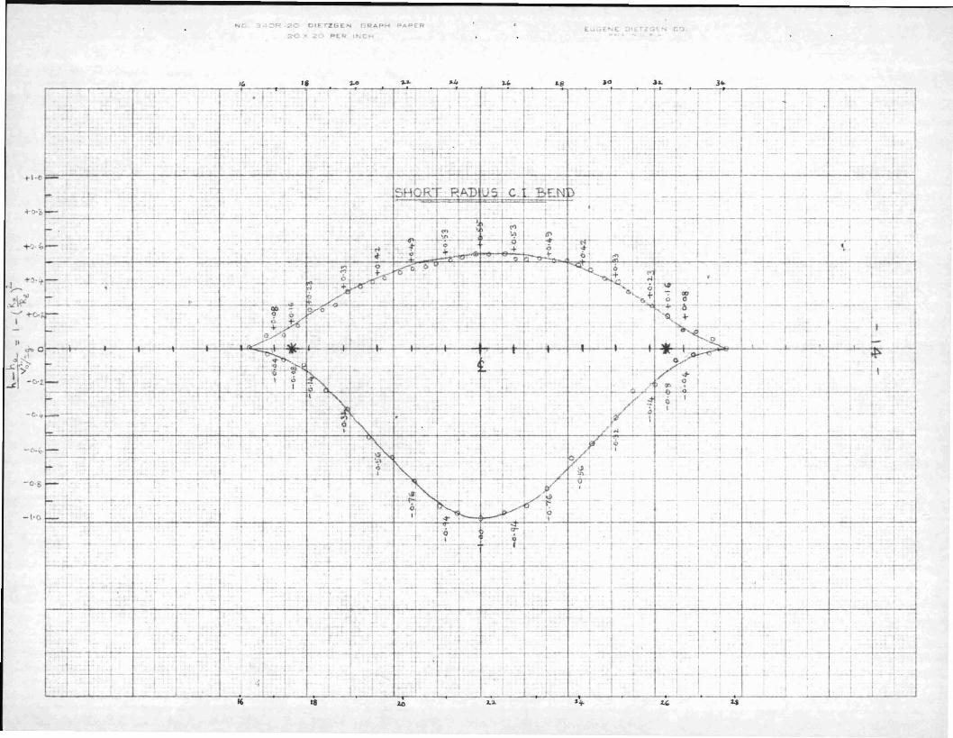
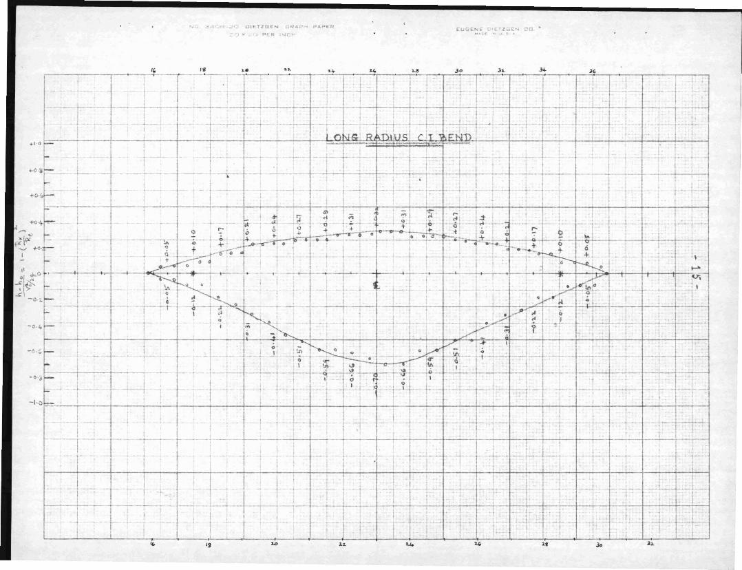
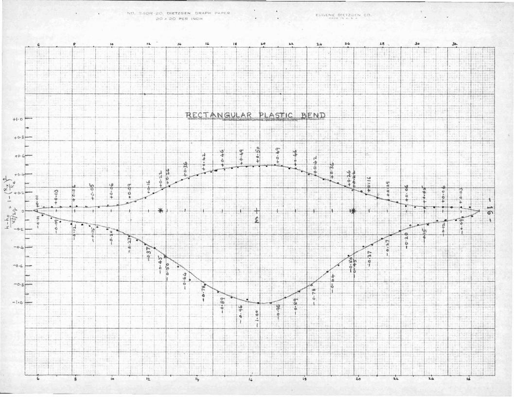
for potential flow were plotted for two circular cast iron 900
In the present set of experiments, the study of the potential
flow was restricted to inner and outer boundaries only which represent
the extremes of the parameter. Graphs of the dimensionless parameter
h-ho
V;/2g'
bends and one rectangular plastic 900 bend.
-6
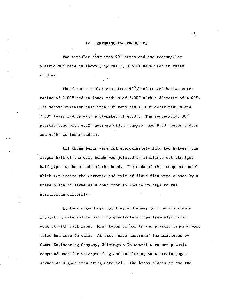
IV.. EXPERIMENTAL PROCEDURE
Two circular cast· iron 900 bends and one rectangular
plastic 900 bend as shown (Figures 2, 3 & 4) were used in these
studies.
The first circular cast iron 900,b~ndtested had an outer
radius of 9.00" and an inner radius of 5.00" with .a diameter of 4.00".
The second circular cast iron 900 bend had 11.00\' outer radius and
7.00" inner radius with a diameter of 4.00". The rectangular 900
plastic benc;l with 4.22" average wip~h (squflre) had 8.80" outer radiusI
and 4.58" as inner radius.
All three bends were cut ~pproximately into two halves; the
larger half of the C.l. bends was jointed by similarly cut straight
half pipes at both ends of the bend. The ends of this complete model
which represents the entrance and exit of fluid flow were closed by a
brass plate to serve as a conductor to induce voltage to the
electrolyte uniformly.
It took a good deal of time and money to find a suitable
insulating material to hold the electrolyte free from electrical
contact with cast iron. Many types of paints and plastic liquids were
tried but were in vain. At last I gaco neoprene' (manufactured by
Gates Engineering Company, Wilmington,Delaware) a rubber plastic
compound used for waterproofing and insulating SR-4 strain gages
served as a good insulati.ng material. The brass plates at the two
-7
ends were insulated with fibre sheets attached to the straight C.L
half-pipes, The whole interior surface of this model was coated
uniformly with gaco neoprene. This coating was allowed to dry for two
days and a second coat applied, then the whole model was installed on
a table by levelling it carefully . A scale was marked on the
horizontal upper surface of the wall of the pipe which was painted
white to indicate the position of the electrodes introduced into the
electrolyte along either inner or outer boundaries of the electrolyte.
Copper sulphate solution (electrolyte, approximately one
half oz. per gallon of water) was poured into this model carefully to
fill up to the central plane, Two electrodes, thin pointed copper
wires, held in tight fitting holes in a small fibre sheet and with a
. rigid spacer served as contact pointers,
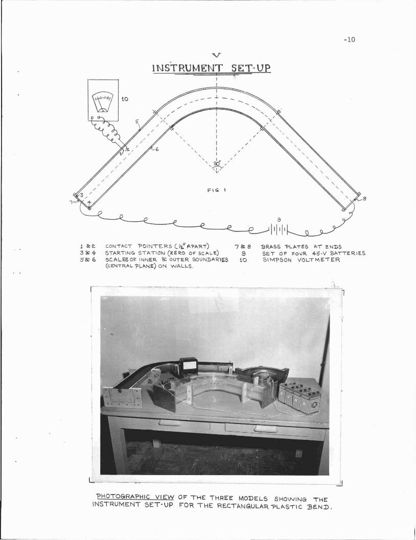
A potential of 45 volts was applied to the brass plates at
the~nds by a set of four-45-V batteries connected in parallel circuit,
Tilus by applying this voltage to the electrolyte (conductor) held in
the geometrically similar model, a potential field analogous to that
of its fluid prototype is developed within the conductor. The contact
pointer connected to a Simpson Voltmeter was br·ought into contac twi th
the conductor at the inner or outer boundaries and voltages were
recorded from one end to the other end, the station along the model
boundary being known from the scale marked thereon, Care was taken to
immerse the ends of the two electrodes of the contact pointer to a
small constant depth as near the boundary as possible, The two
-8
electrodes were painted leavtng the lower tip exposed to facilitate
constant area of contact with the electrolyte. The readi.ngs were
restricted only to the inner and outer boundaries, though the tests
could be repeated to include any point within the conductor in
obtaining equipotential lines.
This experiment was conducted on two C.I. circular 90 0 bends
sand one rectangular platic 900 bend. The instrumentation and the
A
set-up was simple compared to the methods used by previous
investigators in this field. The graphs of the di~ensionless
h-hparameter 0 and the tabulated readings for each of the three
V~/2gabove models are presented .herein. In the actual flow pattern in bends
h·-ho is found to depend upon X = Ric (see Part VIII for symbols)
V~/2g
These results of potential flow pattern could be compared
to the flow of actual flui.d in three dimensions in correlating ,the
bend coefficients of curved bends which can be made to serve as
inexpensive~lbowmeters. The degree of precision in this method is
limited t~ the sensitivity of the voltmeter used and the accuracy with
which the contact pointer was held near the point desired.
-9
. :......
V.- MOD~LSI
C\RCULAR SHORI RADIUS C.I. BENDII "",<-g.od'
SE.CTION· AA
Flli. 3
/ __', -C,'RCULAR LONG RADIUS C.1. BEND
~/ \.,~ :r; '["
o
SECTION·:J;l'
RECTANGULAR 'PLASTIC "BEND
~i------:
o cl •1:. .
SECTION - CC
,\
a
1
-10
v.INSTRUMENT SET·UP.
CON,ACT 'POINTE.RS ('It!: A'l'AR,)STAR,ING- STAll ON (ZERO OF SCALl::)
SCALES 01= INNE.R &; ollTER OOUN3)AQ'~S
(CEl.l'RAL 'PL~NE) ON WALLS.
7~8
910
'BRASS 1>L,e..,ES "'T a N'DSSET OF FOVR 4-5·V BAT'ERIE.S5\Mr'50N VOLTMEiER
'PHOTOGRAPHIC VI EW OF THE THREE MODEl...S SHOWINa THEINSTRUMENT SET-UP FOR THE RECTANGULA"R "PLASTIC :BE.ND.
1
-11
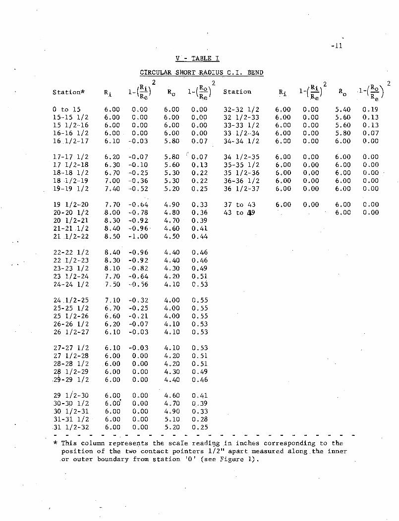
V- TABLE I
CIRCULAR SHORT RADIUS C.I. BEND2 2
1_(Ri)22
Station* Rl 1- (Ri) Ro 1_(:0 ) Station Ri Ro l_(Ro )Re e Re Re
0 to ~5 6.00 0.00 6.00 0.00 32-32 1/2 6.00 0.00 5.40 0.1915-15 1/2 6.00 0.00 6.00 0.00 32 1/2-33 6.00 0.00 5.60 0.1315 1/2-16 6.00 0.00 6.00 0.00 33-33 1/2 6.00 0.00 5.60 0.1316-16 1/2 6.00 0.00 6.00 0.00 33.1/2-34 6.00 0.00 5.80 0.0716 1/2-17 6.10 -0.03 5.80 0.07 34-34 1/2 6.00 0.00 6.00 0.00
17-17 1/2 6.20 -0.07 5~80 0.07 34 1/2-35 6.00 0.00 6.00 0.0017 1/2-18 6.30 -0.1.0 5.60 0.13 35-35 1/2 6.00 0.00 6.00 0.0018-18 1/2 6.70 -0.25 5.30 0.22 35 1/2-36 6.00 0.00 6.00 0.0018 1/2-19 7.00 ·,0.36 5.30 0.22 36-361/2 6.00 0.00 6.00 0.0019-19 1/2 7.40 -0.52 5.20 0.25 36 1/2:-37 6.00 0.00 6.00 0.00
19 1/2-20 7.70 -0.64 4.90 0.33 37 to 43 6.00 0.00 6.00 0.0020-20 1/2 8.00 -0.78 4.80 0.36 43 to 49 6.00 0.0020 1/2-21 8.30 -0.92 4.70 0.3921-211/2 8.40 -0.96' 4.60 0.4121 1/2-22 8.50 -LOO 4.50 0.44
22-22 1/2 8.40 -0.96 4.40 0.46221/2-23 8.30 -0.92 4.40 0.4623-23 1/2 8.1.0 -0.82 4.30 0.4923 1/2-24 7.70 -0.64 4.20 0.5124-24 1/2 7050 -0 . .56 4.10 0.53
24 1/2-25 7.10 -0.32 4.00 0.5525-25 1/2 6.70 -0.25 4.00 0.5525 1/2-26 6.60 -0.21 4.00 0.5526-26 1/2 6.20 -0.07 4.10 0.5326 1/2-27 6.10 -0.03 4.10 0.53
27-27 1/2 6.10 -0.03 4.10 0.5327 1/2-28 6.00 0.00 4.20 0.5128-28 1/2 .6.00 0.00 4.20 0.512~ 1/2-29 6.00 0.00 4.30 0.4929-29 1/2 6.00 0.00 4.40 0.46
29 1/2-30 6.00 0.00 4.60 0.4130-30 1/2 6.00' 0.00 4.70 0,.3930 1/2-31 6.00 0.00 4.90 0.3331-31 1/2 6.00 0.00 5.10 0.2831 1/2-32 6.00 0.00 5.20 0.25
* This column represents the scare ~eadigg .ininches corresponding to theposition of the two contact pointers 1/2" apart measured along the inneror outer boundary from station '0 I (see Figure 1).
-1.2
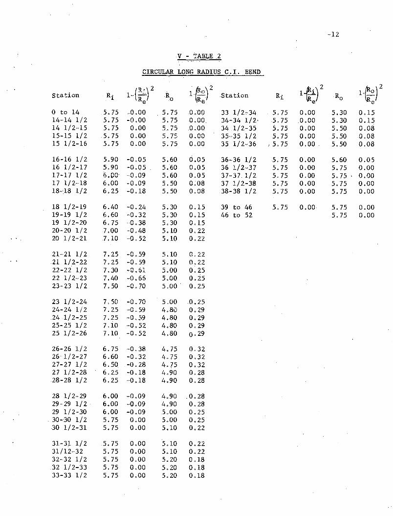
V - TABLE 2
CIRCULAR LONG RADIUS C.l. BEND
Station R (Ri) 2 R 1~:)2 Station Ri 1~i)2 Ro l{ot1- -. i Re '.0 e .. e
a to 1.4 5.15 ,0.00 5.7.5 0.00 33 1/2'0"34 5.15 0.00 5.30 0.1..514-14 1/2 5.15 -0.00 5.75 0.00 34-34 1/2' 5.15 ,a .00 5.30 0.1.514 1./2-1.5 5.75 0.00 5.75 0.00 34 1/2-35 5.75 0.00 5.50 0.0815-15 1/2 5.75 0.00 5.75 0.00 35~35 1/2 5.75 0.00 5.50 0.0815 1/2-1.6 5.75 0.00 5.75 0.00 3.51/2~36 I 5.75 0.00 . 5.50 0.08
16-16 1/2 5.90 -0.05 5.60 0.05 36-36 1/2 5.75 0.00 5.60 0.0516 1./2-17 5.90 -0.05 . 5.60 0.0.5 36 1/2~31 5.75 0.00 .5.75 0.00'11-11 1/2 6.00 -0.09 5.60 0.0.5 37-31 1/2 5.75 0.00 5.75 . 0.0017 1/2-18 6.00 -0.09 5.50 0.08 37 1/2~38 5.75 0.00 5.75 0.0018..18 1/2 6.25 -0.1.8 5.50 0.08 38-38 1/2 5. '75 0.00 5.75 0.00
18 1/2-19 6.40 -0.24 5.30 0.15 39 to 46 5.7.5 0.00 5.75 0.0019-19 1/2 6.60 -0.32. 5.30 0.15 46 to 52 5.75 0.0019 1/2-20 6.75 -a .38 5.30 0.1520-20 1/2 1.00 -0.48 5.10 0.22
.. 20 1/2-21 7.10 -0.52 5.10 0.22
21-21 1/2 7.25 -0.59 5.10 0.2221 1/2-22 7.25 -0.59 5.10 0.2222-2z' 1/2 7.30 -0.61 5.00 0.2522 1/2-23 .7.40 -0.66 5.00 0.2523-23 1/2 7.50 -0.70 5.00 - 0.25
23 1/2-24 7.50 -0.70 5.00 0.2524-24 1/2 7.25 ··0 . .59 4.80 0.29.24 1/2-25 7.25 -0.59 4.80 0.2925-25 1/2 7.10 -0.52 4.80 0.2925 1/2-26 1.10 -0.52 4.80 0. 29
26-26 1/2 6.75 -0.38 4.75 0.3226-1./ 2-21 6.60 -0.32 4.75 0.3227-'2,.7 1/2 6.50 -0.28 4.15 0.3227 1/2-28 6.25 -0 .18 4.90 0.2828-28 1/2 6.25 -0.18 4.90 0.28
28 1/2-29 .6.00 -0.09 4.90 .0.2829-29 1/2 6.00 -0.09 4.90 0.2829 1/2-30 6.00 -0.09 5.00 0.25
- 30-30 1/2 5.75 0.00 5.00 0.2530 1/2-31 5.75 0.00 5.10 0.22
31-31 1/2 5.75 0.00 5.10 0.2231/12-32 5.75 0.00 5.10 0.2232-32 1/2 5.75 0.00 5.20 0.1832 1/2-33 5.75 0.00 5.20 0.1833-33 1/2 5.15 0.00 5.20 0.18
~·13
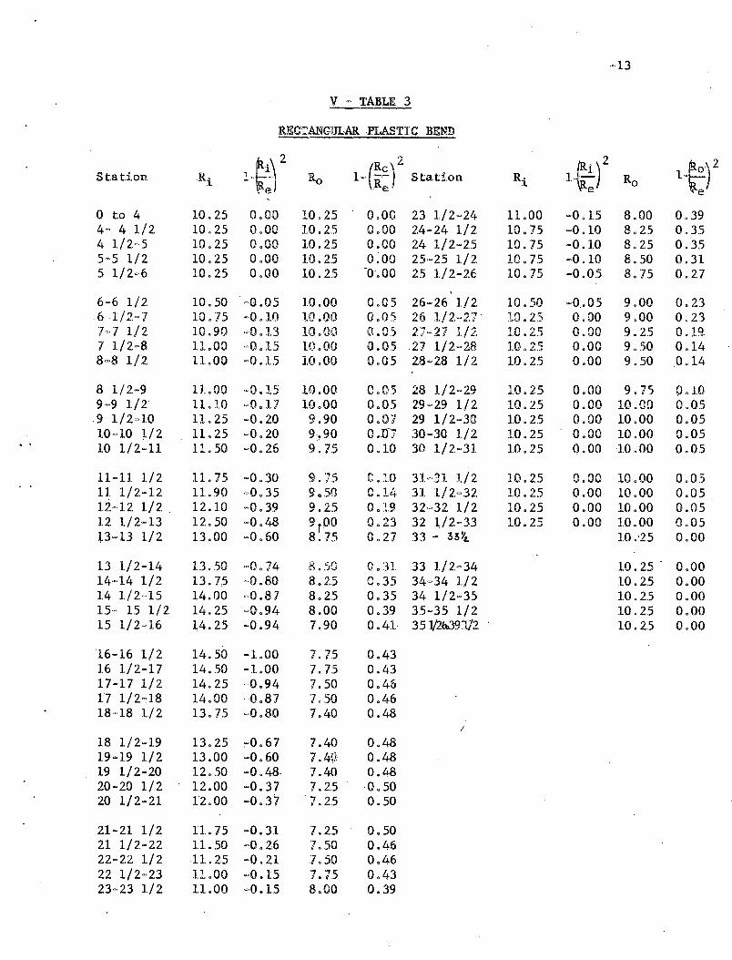
V - TABLE 3
RECTANGULAR PLASTIC BEND
l~f (RO
)
2 2~O)21~:)Station Ri Ro 1- R
e_ StaUon Ri Ro l~
a to 4 10.25 0.00 10.25 0.00 23 1/2=2/+ 11.00 -a .15 8.00 0.394·· 41/2 10.25 0.00 1.0.25 0.00 24-24 1/2 10.75 ~0.10 8.25 0.354 1/2-5 10.25 0.00 10.25 0.00 24 1/2=25 10. '75 -0.10 8.25 0.355-51/2 10.25 0.00 10.25 O~OO 25···25 1/2 10.75 -0.10 8.50 0.315 1/2-6 10.2.5 0.00 10.25 -0-.00 25 1/2=26 10.75 -0.05 8.75 0.27
6-6 1/2 10.50 -0.05 10.00 0.05 26-26 1/2 10. SO -0.05 9.00 0.236 1/2··7 10.75 -0.10 10.00 0.05 26 1/2.··2.7 ' 10.25 0.00 9.00 0.237'~ 7 1/2 10 .90 -0.13 }ALOa 0.05 2'7-2'1 1/~ 10.25 0.00 9.25 0.19.J. b
7 1/2-8 11.00 =0.15 io.oO 0.0.5 27 1/2·~28 10.2.5 0.00 9.50 0.148-8 1/2 11.00 -0.15 10.00 0.05 28-28 1/2 10.25 0.00 -9.50 0.14
8 1/2-9 11..00 -0.15 10.00 0.05 28 1/2··29 10.25 0.00 9.75 0.109-9 1/2' 11.10 -0.1'7 10.00 0.05 29-29 1/2 10.25 0.00 10.00 0.0.59 1/2-10 11.25 -0.20 9.90 0.07 29 1/2-30 1.0 • 25 0.00 10.00 0.0510-10 ~/2 11.25 -0.20 9:~90 O.D; 30-30 1/2 1.0.25 0.00 10.00 0.0510 1/2-11 11. 50 ·'0.26 9.75 0.10 30 1/2=31 1.0.25 0.00 1.0.00 0.05
11-11 1/2 11. 75 -0.30 9.'75 0.10 31 c ·31 1/2 10.25 0.00 10.00 0.0511 1/2=12 11.90 -0.35 9 • .50 0.14 31 1/2.-32 10.2..5 0.00 10.00 0.051.2-·12 1/2 . 12.• 10 -0.39 9.25 0.19 32·~.32 1/2 10.25 0.00 10.00 0.0512 1/2-13 12.50 -0.48 grOO 0.2.3 32 1/2~33 10.25 0.00 10.00 0.05P-13 1/2 13.00 -0.60 8.75 0.27 33 - 33 YL 10 .'25 0.00
13 1/2-14 13 • .50 ~O.74 8.S0 0.31 33 1/2=34 10.25 . 0.0014-14 1/2 13.75 -0.80 8.25 0.35 34-34 1/2 10.25 0.0014 1/2~15 14.00 ~O .87 8.2.5 0.35 34 1/2-35 1.0.25 0.0015- 15 1/2 14.25 -0.94 8.00 0.39 35-35 1/2 10.25 0.0015 1/2-16 ~4.25 -0.94 7.90 0.41- 35 J!2t0391/2 10.2.5 0.00
16-16 1/2 1.4.50 -1.00 7.7.5 0.4316 1./2-17 14.50 -LOO 7.75 0.4317-17 1/2 14.25 -0.94 7.50 0.4617 1/2-18 14.00 -0.87 7.50 0.4618-18 1/2 13.75 ~·o.80 7.40 0.48
I
18 1./2-19 13.25 :-0.67 7.40 0.4819-19 1/2 13.00 -0.60 7.4()i 0.4819 1/2-20 12.50 -0.48· 7.40 0.4820-20 1/2 12.00 -0.37 7.25 -0.5020 1/2-21 12.00 -0.37 7.25 0.50
21-21 1/2 n.75 -0.31 7.25 0.5021 1/2-22 11.50 -0.26 7.50 0.4622-22 1/2 11.25 -0.21 7.50 0.4622 1/2-23 11.00 -0.15 '7.75 0.4323-23 1/2 11.00 -0.1.5 8.00 0.39
N( OF~ ~C OIFTZGEN GRAPH PADE"R
20 .. £. PE F« ,. c:,...
_.-
j
I--·r.r
. -1 _ I
!
,II
_1
--, 1 ...' - r. ~j----t-l---;~-~--J
1
, .
a.118"
- ~--
r --
I.
_. - I:
I-~ -1---
I-;-+--.+--:-+.,--t-'-'"---f- -r- r-'
I'f-'-i- l 1 r- ~
1----;- '~I
I--_!,-..-~l~ -+__,_ ---i--.L-~----! . _
1-
t ,.!) I I 1 • . ! I I t
L~"/)~ --~il'-- - '-" Ti'-'1 .- - , '1 -. -;. 1C,f-\OR" p.ADIu~ c~~ ~ENP. , - t. '-', •
~- r- . .- -~- ---r-' I --~-~- - -.-'. ,- - f--r-+-- - -'~
~ . 11 --- - I .' . -' ~ ~ 1- - ~ -~- '- Et_~ .• I _ t'~-I- I ~ + <> ..'(',.- I r .' 1 I I , i~ <. -l- ,,~<>' ....
I! 'I" ..,1 0 I.-/C 0 ~i~', ' ;;:1 .xro -, 1+ ~
'.l"..-. +'~'"f~ " -- 1 '- - - . - - r-r;;P5"'f' ; 1- -~. - ,- . ~'~I"'G i ~ ~ I ,-....'ll ~ _,l__-t_-:-~_~__ '- ~ .-f-- ~-~--t--- - -.... L-.-.-tl _ _
~ ~".:--~ l. ..J-' ,I L1,.V01
L.":"_.. - _.: ,i.· c....,: I 0 JI'I I ~.I.' t I ! • I .. ~~
J:IJr~~of- " : •• - -- -, -t-f~~ 11- -, -' t .. ' ',~-'r--' ,~- ?~,~ -~'1:-! 11
' ~ : : ': Itt f~) I n~-- -y------. :/ ~ : ;: 'I t I I I a I _
-C'¥~--- T- -- ~. r--' - r- -';-_. .-. 1", - '--!', - ._.~ _. ~,I t-- )~ I I I
-(~"f- " '_ ., _._ j I', .j_]~~. r-.L_, l' _ _~/p :~ i._I _ '1. .. jf- ~-j I I f i ?' ""- : ! -,L ~ I. ~.. __ ._.J_ . 1
r I ~_-'---1,-- i I ~~-'I I }¥' -- -~. -- I I
-O-g:- :_I -, -" - - I 'I' . 1- j -f- 0, ! .-Vf~: I - i' t i ' .... I :.-I'CI ~I--=-"':'-'-+_~~_J,~+_~-+_+,_+-__+_:..t.....:...t--I--+-~"_+~~,~=r::::..~rl-~I!..-+---r-~-t------i--;:-T-!:-;!--;.-I-!;1
' !' I " f I?, '; I I I ! ! 1'--1 - --:-'--;- --+ - _. _.- ...,-- 1 1 - . t • - -- j - j-'1I I Iii; __ 1---_ I •__:___ _ I
-:- ·i·: ..: ...~ ··-f ..·1· i ---r I ~ L ~~. ··:I~'-
J ~.u:. I .... i .....EUGENE L ['TZliC"'-l CO •
,... .. ( "" oJ 9 ..
L _.
+0 li I-- _ -<----. __I-
+0.(,1-
I
301fI'
I ; I I I I I I L t
_.L I ~ ,. + " - ~- i .r -~ --~ 1-- r-r;--r- --- ;_. --~. -~ ..----; '-~-l"
-·j:",··-~··-ir--,----"-,,,,-- ----;T: i : I ,I, ~ I I I f I: I.~ 1'- - ,~-- , -J ,,- - r- -~--- '-'-~';-- ._~--- .........--- +- .!.~l _'1-_
1 ,.,-+-I I I •
" I I ,. .1
I
---------I ' II II :
I. I
I t I--T---~~-- :--- riii
'I : I' o, .......~ I -'" I~ \ '", t I _ ! .11 -~ ".., I"y ...... ;, .; I I -+ iJ '.- - 'I -r - -- -~ ..... ~. ~ ~I' If ~ ,t·~--.............J_",,-- -1---," l-T -'r
jI"T'·
f--~_._-+I_----1f--- .._ .~ I... I _'_ •• I I \ ~ ~ I ~.~, I I . -t--:...._+---L'-4-"-::_4-.-":"0---1
-" j>I- 1 I. 1 I J'. j .. ~ _. _ .?_J _~ "= I I I j' 1 I' ~_I'~~:'~ , ~, I .. : 1 1--' -1 ~f-- I- -; -~ L_ 1-- i r-_., _.- .~- -Il 1--
__ _I _- _' ~-+-~,_l' _i_",.'---11--_' +'__1; -..'-+-f-_:...;'_·~-i-._i;-"--1Lf----1; __--+-'-_'...t1_+-_,_,~i·..:.'.:.....+f-._: ,- ,~+ Ti -: 1 " I I I !
-I- . ; ,- - i I I • - --:- - •• - ; - -r-~1-' r- -~- ,-. -+ -~-
.n. ·:'OR e:::.C OIETZGEN
20" 20 PER I
GRAPH
CH
. .
-17
.VI. CONCLUSIONS
The results obtained by this method~fN.ere sufficiently
good, although a high degree of accuracy can not be cla~med. The.re is
greater scope for further research in.this field to obta~nmore precise
values, by improving the model and.the instrument set-up,
Fixed electrodes flush .with the surface of the electrolyte
can usually be located with greater accuracy than can .a movable probe
and they also present less disturbance to the flow •. Factors like
irregularity of joints,movable prc:>ba, irregularity of insulating
,material surface and capacitance were kept at .a minimum by taking .all
possible precautions though some possible error could not be avoided in
this inexpensive but simple instrument set'.up and method .
This is an inexpensive and reasonable method embodying
simplicity, flexibility, economy of time and economy of equipment as
compared with a mathematical solution for three dimensions flow. The
method is restricted to models which have an axis of symmetry.
Regardless of the level of precision attained in these studies, this
method is more accurate than the flow-net plotting technique for two
dimensional problems. This method' represents a practically rapid,
relatively inexpensive method for attackingthree-dimsional problems
for boundaries with a single axis of symmetry, the solution of which
cannot be obtained by flow-net plotting, and which heretofor· have
required an expensive and elaborate modeL It is of interest to note
that all three models were cut from bends which had previously been

. .
-18
used for water flow tests. Thus al~ boundary irregularities or
peculiarities inherent in the flow tests were automatically reproduced
in the anology model .
-19
VI1. ACKNOWLEDGMENTS
The laboratory work performed at Lehigh University was
made possible through student funds allocated by Professor W.J. Eney,
Head of the Department of Civil Engineering and Director of Fritz
Laboratory.
Grateful acknowledgments are due to Mr. Taylor and his
assistant Mr. Quinones (who originated the two-probe technique) and
to Mr. Gosztonyi, Mechanic, Hydraulic Laboratory.
I am grateful to the Department of Civil Engineering for
all the facilities including laboratory equipment and .the library that
were freely made available to me at all times. The photo taken by
Mr. Florance is also gratefully acknowledged.
The writer is particularly indebted to Professor Murray Burns
McPherson for his invaluable guidance and encouragement throughout this
investigation.
R .. -
ri
=
r o =
C .=
X -
V0
-20
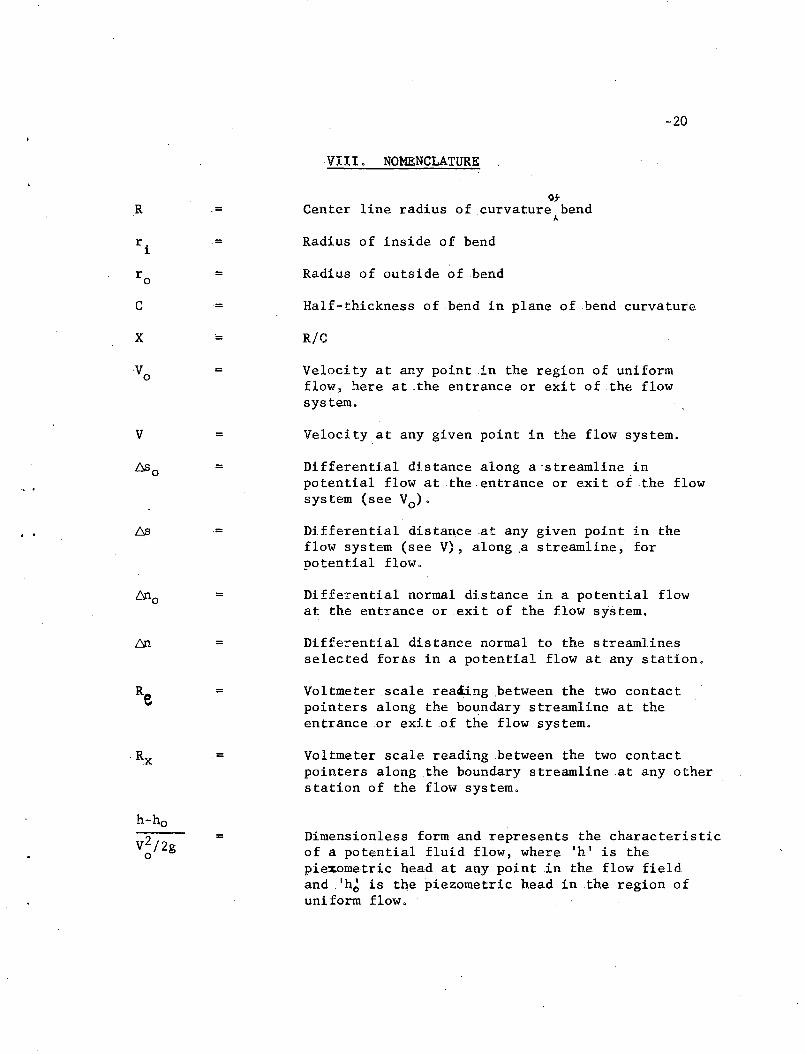
.VI I I • NOMENCLATURE
otCenter line radius of curvature bend
A
Radius of inside of bend
Radius of outside of bend
Half-thickness of bend in plane of bend curvature
R/C
Velocity at any point in the region of uniformflow, here at .the entrance or exit of the flowsystem.
..
V
/:':,so
t0no
h-ho
V2/2go
=
=
=
=
=
=
=
Velocity at any given point in the flow system.
Differential distance along a 'streamline inpotential flow at the entrance or exit of. the flowsystem (see Vo)'
Differential distance at .any given point in theflow system (see V), along ,a streamline, forpotential flow.
Differential normal distance in a potential flowat the entrance or .exit of the flow system.
Differential dista.nce normal to the streamlinesselected forAs ina potential flow at any station.
Voltmeter scalereaiing .between the two contactpointers along the boundary streamline at theentrance or exit of the flow system.
Voltmeter scale reading .between the two contactpointers along .the boundary streamline at any otherstation of the flow system.
Dimensionless form and represents the characteristicof a potential fluid flow, where Ih' is thepiexometric head at any point in the flow fieldand Ih~ is the piezometric head in the region ofuni form flow.
=21
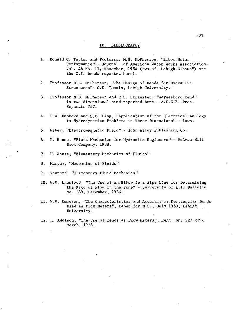
IX. BIBLIOGRAPHY
1. . Donald C. Taylor and .Pr.ofessor M. B. McPherson, "Elbow MeterPerformance" - Journal of American Water Works AssociationVol. 46 No. 11, November, 1954 (two of 'LehighElbows") arethe C.l. bends reported here).
2. Professor M.B. McPherson, liThe Design of Bends for HydraulicStructures"- C.E. Thesis, Lehigh University.
3, ·ProfessorM.B. McPherson andR.S. Strausser, ''Waynesboro Bend"is two=dimensi.onalbend reported here - A.S,C.E, .Proc.Separate 747,
4. P.G. Hubbard and S.C. Ling, "Application.of the Electrical Anologyto Hydrodynamics Problems in Three Dimensions II - Iowa.
5. Weber, IElectromagneticField" - JonnWiley J;\lblishing Co.
6, H. Rouse, "F1uid Mechanics for Hydraulic Engineers II - McGraw HillBook. Company, 1938.
7. H. Rouse, "E1ementaryMechanics of Fluids"
8. Murphy, "Mechanics of Fluids"
9 ..Vennard , "Elementary Fluid Mechanics"
10. W.M. Lansford) "The Use of an.Elbow in a Pipe Line for Determiningthe Rate of Flow in thePipe" - University of Ill. BulletinNo. 289, December, 1936.
ll.W.V. Onnneren, liThe Characteristics and Accuracy of Rectangular BendsUsed as Flow Meters", Paper for M.S., July 1953, LehighUniversity.
12. H. Addison, liThe Use of Bends as Flow Meters", Engg. pp. 227-229"March, 1938.
-22
X~ VITA
The. wri te.rwas born on 8th February 1922 at Doo.ballapur ,
Mysore.State, South India and .is the fourth (youngest) son of,
Mr. D,S. Subbarayappa and Mrs, Chowdamma,
Studied in elementary and secondary schools at Dodballapur
and later passed the college preparatory course (called Intermediate
Examination) in BangaloreCity, .South India with distinction in first
class i.n 1940.
Entered the Mysore Univers:lty College of Engineering,
Bangalore and passed the degree of Bachelor of .CivilEngine.ering
.withdistinction obtaining .a first class in 1945 •
.During September 1945, entered service with the Mysore 'State
Government as a Hydraulic Research Section Officer and later served
as a Lecturer inCivi1.Engineering in the Mysore University. Later
worked as an AssistanLEp.gineer in the Mysore.State Engineering
.Department being in-charge of survey, design and execution of various
Civil Engineering works wi thEngineeririg per,sonnel under direction,
Served as an Assistant Professor of Civil Engineering in
the Mysore University before departure to U.S,A. (August .1955)
for advanced study in Civil Engineering at Lehigh University.
This experience totals 4 years in teaching .and a professional
experience of6 years.

..
. .
Entered Lehigh University as a Gotshall scholar in Civil
.Engineering durin~.September 1955 for advanced study in.Civil
Engineering at Lehigh University, Bethlehem, Pennsylvania, U.S.A .
~23