Embed Size (px)
Citation preview
1
Fractional order control and simulation of wind energy systems with PMSG/full-power converter topology
R. Melício a, V.M.F. Mendes b, J.P.S. Catalão a,*
a Department of Electromechanical Engineering, University of Beira Interior, R. Fonte do Lameiro, 6201-001 Covilha, Portugal
b Department of Electrical Engineering and Automation, Instituto Superior de Engenharia de Lisboa, R. Conselheiro Emídio Navarro, 1950-062 Lisbon, Portugal
Received 25 May 2009
Abstract This paper presents a new integrated model for the simulation of wind energy systems. The proposed model is more realistic and accurate, considering a variable-speed wind turbine, two-mass rotor, permanent magnet synchronous generator (PMSG), different power converter topologies, and filters. Additionally, a new control strategy is proposed for the variable-speed operation of wind turbines with PMSG/full-power converter topology, based on fractional-order controllers. Comprehensive simulation studies are carried out with matrix and multilevel power converter topologies, in order to adequately assert the system performance in what regards the quality of the energy injected into the electric grid. Finally, conclusions are duly drawn. © 2009 Elsevier Ltd. All rights reserved. Keywords: Wind energy; modeling and simulation; permanent magnet synchronous generator; fractional-order control
1. Introduction
Wind energy is the fastest growing energy technology in terms of percentage of yearly growth of
installed capacity per technology source [1].
In Portugal, the wind power goal foreseen for 2010 was established by the government as 3750 MW
and that will constitute some 25% of the total installed capacity by 2010 [2]. This value has recently been
raised to 5100 MW, by the most recent governmental goals for the wind sector. Hence, Portugal has one
of the most ambitious goals in terms of wind power, and in 2006 was the second country in Europe with
the highest wind power growth.
* Corresponding author. Tel.: +351 275 329914; fax: +351 275 329972.
E-mail address: [email protected] (J.P.S. Catalão).

2
As wind energy is increasingly integrated into power systems, the stability of already existing power
systems is becoming a concern of utmost importance [3]. Also, network operators have to ensure that
consumer power quality is not deteriorated. Hence, the total harmonic distortion (THD) should be kept as
low as possible, improving the quality of the energy injected into the electric grid [4]. The new technical
challenges emerging due to increased wind power penetration, dynamic stability and power quality imply
research of more realistic and accurate models for wind energy systems.
Power-electronic converters have been developed for integrating wind power with the electric grid.
The use of power-electronic converters allows not only for variable-speed operation of a wind turbine, but
also for enhancement on power extraction [5]. In a recent overview of different wind generator systems
[6], it is shown that variable-speed conceptions equipped with power-electronic converts will continue to
dominate and be very promising technologies for large wind farms.
Variable-speed control is better than constant-speed control and is known for at least a decade [7].
In a variable-speed wind turbine with full-power converter, the wind turbine is directly connected to the
generator and the generator is completely decoupled from the electric grid. Of all the generators used in
wind turbines, the permanent magnet synchronous generator (PMSG) is the one with a significant
advantage: it is stable and secure under normal operating conditions; and comparing with a wound
synchronous generator, it is smaller and does not need a direct current power source for field excitation.
Accurate modeling and control of wind turbines have high priority in the research activities all over
the world [8]. Also, understanding the harmonic behavior of variable-speed wind turbines is essential in
order to analyze their effect on the electric grids where they are connected [9]. At the moment, substantial
documentation exists on modeling and control issues for the doubly fed induction generator (DFIG) wind
turbine. But this is not the case for wind turbines with PMSG and full-power converter.
In this paper, a variable-speed wind turbine is considered with PMSG and different power converter
topologies: matrix, and multilevel.
Matrix converters have received considerable attention during the past decades, since they may
become a viable alternative to back-to-back converters [10]. The matrix converter is capable of
converting the variable AC from the generator into constant AC to the electric grid in one stage. A
technology review of matrix converters can be seen in [11]. The converter is smaller, lighter and more
reliable than conventional converters, representing a good alternative for variable-speed operation of wind

3
energy systems [12]. One of the major drawbacks of a matrix converter is that 18 total switches are
required, causing an increase in converter semiconductor cost. Also, industrial wide use of matrix
converter is still very limited due to certain undesirable characteristics: its sensitivity to distortion in input
power supply due to the lack of reactive component in the power circuit, and its sensitivity to the rapidly
fluctuating input voltage frequency when used in wind energy systems [13].
Multilevel converters are widely used in high-voltage and high-power applications [14, 15], because
they allow operations at higher dc-link voltage levels, avoiding the problems of the series interconnection
of devices [16]. Compared to the conventional two-level converter topology, multilevel converters
provide several advantages: their ability to meet the increasing demand of power ratings and power
quality associated with reduced harmonic distortion, lower electromagnetic interference, and higher
efficiencies [17]. Hence, multilevel converters are a good tradeoff solution between performance and cost
in high-power systems [18]. A survey of topologies, controls, and applications for multilevel inverters can
be seen in [19]. Multilevel converters are, however, limited by the following drawbacks: voltage
unbalances, high component count, and increased control complexity. A critical issue in multilevel
converters is the design of the DC-link capacitors. Thus, special attention should be paid to the unbalance
in the capacitors’ voltage of multilevel converters, which may produce a malfunction of the control. One
possible design of the DC-link is given in [20].
Several papers have been issued on matrix and multilevel power converters, but mainly using
simplified models to describe the wind energy system or the control strategies themselves. However, the
increased wind power penetration, as nowadays occurs for instance in Portugal, requires new models for
the simulation of wind energy systems, more realistic and accurate, and new control strategies, improving
performance of disturbance attenuation and system robustness. These concerns are all accounted for in
our paper.
As a new contribution to earlier studies, an integrated model for the simulation of wind energy
systems with different power converter topologies is presented in this paper. Additionally, a new
fractional-order control strategy is proposed for the variable-speed operation of wind turbines with
PMSG/full-power converter topology.

4
Harmonic emissions are recognized as a power quality problem for modern variable-speed wind
turbines. Understanding the harmonic behavior of variable-speed wind turbines is essential in order to
analyze their effect on the electric grids where they are connected [9]. Hence, comprehensive simulation
studies are carried out with matrix and multilevel power converter topologies, in order to adequately
assert the system performance in what regards the quality of the energy injected into the electric grid.
This paper is organized as follows. Section 2 presents the integrated modeling of the wind energy
system with different power converter topologies: matrix and multilevel. Section 3 presents the new
fractional-order control strategy for the variable-speed operation of wind turbines with PMSG/full-power
converter topology. Section 4 provides the power quality evaluation by Fast Fourier Transform (FFT) and
THD. Section 5 presents the simulation results obtained on a case study. Finally, concluding remarks are
given in Section 6.
2. Integrated modeling
The notation used throughout the paper is stated as follows.
tP Mechanical power of the turbine.
Air density.
A Area covered by the rotor.
R Radius of the area covered by the blades.
u Wind speed value upstream of the rotor.
pc Power coefficient.
Pitch angle of the rotor blades.
Tip speed ratio.
t Rotor angular speed at the wind turbine.
tJ Moment of inertia for blades and hub.
tT Mechanical torque.
dtT Resistant torque in the wind turbine bearing.
atT Resistant torque in the hub and blades.
tsT Torsional stiffness torque.

5
g Rotor angular speed at the generator.
gJ Moment of inertia for the rotor of the generator.
dgT Resistant torque in the generator bearing.
agT Resistant torque due to the viscosity of the airflow in the generator.
gT Electric torque.
di , qi Stator currents.
dL , qL Stator inductances.
du , qu Stator voltages.
p Number of pairs of poles.
M Mutual inductance.
dR , qR Stator resistances.
fi Equivalent rotor current.
2.1 Wind turbine
The mechanical power of the turbine is given by:
pt cuAP 321 (1)
The computation of the power coefficient requires the use of blade element theory and the knowledge
of blade geometry. The power coefficient is a function of the pitch angle of rotor blades and the tip seed
ratio, which is the ratio between blade tip speed and wind speed upstream of the rotor. In this paper, the
numerical approximation developed in [21] is followed, where the power coefficient is given by:
i
ip ec
4.1814.2 2.13002.058.015173.0
(2)
)1(003.0
)02.0(1
1
3
i (3)
The mechanical power acquired from the wind is given by (1) to (3). From (2), the maximum power
coefficient is given for a null pitch angle and it is equal to:
4412.0max pc (4)
6
corresponding to an optimal tip speed ratio equal to:
057.7opt (5)
In order to achieve maximum power, the tip speed ratio should be kept at the value corresponding to
the global maximum for the power coefficient [5]. Hence, the rotor angular speed at the wind turbine is as
a function of the maximum mechanical power maxtP , given by:
optt
max5
max3 2
p
t
cR
P
(6)
A maximum power point tracking (MPPT) is used in determining the optimal rotor angular speed at the
wind turbine for each wind speed to obtain maximum rotor power [5].
When regulating the wind system under the specification of maximum power, it must be taken into
account that turbine power must never be higher than generator value for the rated power. Once generator
rated power is reached at rated wind speed it must be limited. For variable-speed wind turbines, a blade
active pitch angle controller must be included [22], employing pitch control when reducing the angle of
attack: increasing the blade pitch angle reduces the power coefficient and maintain the power at its rated
value. When rated turbine speed is reached, control strategy must be changed so that a higher wind
velocity no longer increases turbine speed but increases generated power until generator rated power;
increases in rotor speed of about 10% are allowed during transients because of the slow pitch control
response [23].
Fig. 1 shows the power coefficient as a function of the tip speed ratio, parameterized in function of
the pitch angle.
"See Fig. 1 at the end of the manuscript".
2.2 Two-mass drive train model
An accurate way to model a mechanical drive train of a wind energy system is to model the rotor as a
number of equivalent discrete masses connected together by springs and dampers. A two-mass model for
the mechanical drive train is considered in this paper: one mass represents the blades and the hub joint,
the wind turbine moment of inertia, and the other mass represents the generator moment of inertia. The
configuration of the simulated mechanical drive train is shown in Fig. 2.
"See Fig. 2 at the end of the manuscript".

7
The equations for the two-mass model are based on the torsional version of the second law of
Newton, deriving the state equation for the rotor angular speed at the wind turbine and for the rotor
angular speed at the generator, respectively given by:
tsatdttt
t TTTTJdt
d
1 (7)
gagdgtsg
g TTTTJdt
d
1 (8)
2.3 Generator
The model for the PMSG is the usual one, where the state equations for modeling the PMSG stator
currents, using motor machine convention, are given by:
ddqqgdd
d iRiLpuLdt
di
1 (9)
qqfddgqq
q iRiMiLpuLdt
di
1 (10)
In order to avoid demagnetization of permanent magnet in the PMSG, a null stator current 0di is
imposed [24]. The electric power is given by:
Tfqdfqdg iiiuuuP ][][ (11)
2.4 Matrix converter
The matrix converter is an AC-AC converter, with nine bidirectional commanded insulated gate
bipolar transistors (IGBTs) ijS . It is connected between a first order filter and a second order filter. The
first order filter is connected to a PMSG, while the second order filter is connected to an electric network.
A switching strategy can be chosen so that the output voltages have nearly sinusoidal waveforms at the
desired frequency, magnitude and phase angle, and the input currents are nearly sinusoidal at the desired
displacement power factor [25]. A three-phase active symmetrical circuit in series models the electric
network. The phase currents injected in the electrical grid are modeled by the state equation using, given
by:
)(1
jfjnfjn
fj uiRuLdt
di }6,5,4{j (12)

8
The configuration of the simulated wind energy system with matrix converter is shown in Fig. 3.
"See Fig. 3 at the end of the manuscript".
The IGBTs commands ijS are given in function of the on and off states, as follows:
)off(,0)on(,1
ijS }3,2,1{, ji (13)
For the matrix converter modeling it is considered that:
3
11
jijS }3,2,1{i (14)
3
11
iijS }3,2,1{j (15)
The vector of output phase voltages is related to the vector of input phase voltages through the
command matrix [26], as follows:
c
b
a
c
b
a
C
B
A
vvv
Svvv
SSSSSSSSS
vvv
][
333231
232221
131211
(16)
The vector of input phase currents is related to the vector of output phase currents through the
command matrix [26], as follows:
TCBA
TTcba iiiSiii ][][][ (17)
2.5 Multilevel converter
The multilevel converter is an AC/DC/AC converter, with twelve unidirectional commanded IGBTs
ijS used as a rectifier, and with the same number of unidirectional commanded IGBTs used as an
inverter. A group of four IGBTs linked to the same phase constitute a leg j of the converter. The rectifier
is connected between the PMSG and a capacitor bank. The inverter is connected between this capacitor
bank and a second order filter, which in turn is connected to an electric grid. Again, a three-phase active
symmetrical circuit in series models the electric grid [27, 28]. The phase currents injected in the electric
grid are modeled by the state equation (12).

9
The configuration of the wind energy system with multilevel converter is shown in Fig. 4.
"See Fig. 4 at the end of the manuscript".
The switching variable j of each leg j is a function of the states ijS of the converter. The index i
with }4,3,2,1{i identifies the IGBT. The index j with }3,2,1{j identifies the leg for the rectifier and
}6,5,4{j identifies the inverter one. The three valid conditions [29] for the switching variable of each
leg j are given by:
0)or(and1)and(,1
0)or(and1)and(,0
0)or(and1)and(,1
2143
4132
4321
jjjj
jjjj
jjjj
j
SSSS
SSSS
SSSS
}6,...,1{j (18)
A switching variable j1 is associated with the two upper IGBTs in each leg j ( jS1 and jS 2 ), and
also a switching variable j2 is associated with the two lower IGBTs ( jS3 and jS 4 ), respectively given
by:
2
)1(1
jjj
;
2)1(
2jj
j
}6,...,1{j (19)
Hence, each switching variable depends only on the conducting and blocking states of the IGBTs.
The voltage dcv is the sum of the voltages 1Cv and 2Cv in the capacitor banks 1C and 2C , modeled by
the state equation, given by:
6
42
3
12
2
6
41
3
11
1
11
jjj
jjj
jjj
jjj
dc iiC
iiCdt
dv (20)
3. Control strategy
3.1 Fractional-order controller
A novel control strategy based on fractional-order PI controllers is proposed for the
variable-speed operation of wind turbines with PMSG and full-power converters. Fractional calculus
theory is a generalization of ordinary differentiation and integration to arbitrary (non-integer) order [30].
Recently, applications of fractional calculus theory in practical control field have increased significantly
[31].

10
The fractional-order differentiator can be denoted by a general operator ta D [32], given by:
0)(
0)(
0)(
,)(
,1
,
t
a
ta
d
dtd
D (21)
where is the order of derivative or integrals, )( is the real part of the . The mathematical
definition of fractional derivatives and integrals has been the subject of several descriptions. The most
frequently encountered one is called Riemann–Liouville definition, in which the fractional-order integral
is given by:
t
ata dfttfD
)()()(Γ
1)( 1 (22)
while the definition of fractional-order derivatives is:
t
a nn
n
ta dt
fdtd
ntfD
1)()(
)(Γ1
)( (23)
where:
0
1)(Γ dyeyx yx (24)
is the Euler’s Gamma function, a and t are the limits of the operation, and is the number identifying
the fractional order. In this paper, is assumed as a real number that satisfies the restrictions 10 .
Also, it is assumed that 0a . The following convention is used: tt0 DD .
The other approach is Grünwald–Letnikov definition of fractional-order integral, given by:
)()(!)(
lim)(00
hrtfr
rhtfD
hat
rta
h
(25)
while the definition of fractional-order derivatives is:
)()1(!
)1()1(lim)(
00hrtf
rrhtfD
hat
r
rta
h
(26)
where the binomial coefficients 0r are given by: definition, given by:
!
)1()1(,1
0 rr
r
(27)

11
An important property revealed by (25) is that while integer-order operators imply finite series, the
fractional-order counterparts are defined by infinite series. This means that integer operators are local
operators in opposition with the fractional operators that have, implicitly, a memory of all past events.
The differential equation of the fractional-order PI controller, 10 , in time domain, is given
by:
)()()( teDKteKtu tip (28)
where pK is a proportional constant and iK is an integration constant. Taking 1 in (28), a classical
PI controller is obtained. Hence, using Laplace transforms the transfer function of the fractional-order
PI and proportional integral PI controllers are respectively given by:
sKKsG ip)( (29)
sKKsG ip )( (30)
3.2 Converters control
Power converters are variable structure systems, because of the on/off switching of their IGBTs. As
mentioned previously, the controllers used in the converters are respectively proportional integral and
fractional-order PI controllers. Pulse width modulation (PWM) by space vector modulation (SVM)
associated with sliding mode is used for controlling the converters.
The sliding mode control strategy presents attractive features such as robustness to parametric
uncertainties of the wind turbine and the generator as well as to electric grid disturbances [33].
Sliding mode controllers are particularly interesting in systems with variable structure, such as
switching power converters, guaranteeing the choice of the most appropriate space vectors. Their aim is
to let the system slide along a predefined sliding surface by changing the system structure.
The power semiconductors present physical limitations that have to be considered during design
phase and during simulation study. Particularly, they cannot switch at infinite frequency. Also, for a finite
value of the switching frequency, an error e will exist between the reference value and the control
value. In order to guarantee that the system slides along the sliding surface ),( teS , it has been proven
that it is necessary to ensure that the state trajectory near the surfaces verifies the stability conditions [26]
given by:

12
0),(
),( dt
tedSteS
(31)
in practice a small error 0 for ),( teS is allowed, due to power semiconductors switching only at
finite frequency. Consequently, a switching strategy has to be considered, given by:
),( teS (32)
The output voltages of matrix converter are switched discontinuous variables. If high enough
switching frequencies are considered (much higher than the input and output matrix converter
fundamental frequencies), it is possible to assume that in each switching period sT , the average value of
the output voltages is nearly equal to their reference average value. Hence, the following equality is
assumed:
s
s
Tn
nTsvdtv
T)1( *1
(33)
Similar to output voltages, the input current average value is nearly equal to their reference average
value. Hence, the following equality is also assumed:
s
s
Tn
nT qqs
idtiT
)1( *1 (34)
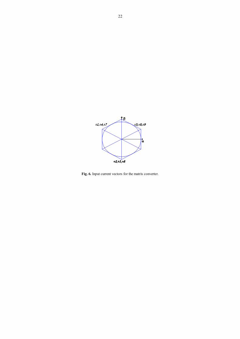
The output voltage vectors and the input current vectors in the plane for the matrix converter are
shown in Fig. 5 and Fig. 6, respectively.
"See Fig. 5 at the end of the manuscript".
"See Fig. 6 at the end of the manuscript".
The output voltage vectors in the plane for the multilevel converter are shown in Fig. 7.
"See Fig. 7 at the end of the manuscript".
4. Power quality assessment
The harmonic behavior computed by the FFT is based on Fourier analysis. If is )(X a continuous
periodical signal with period of T and satisfies Dirichlet condition, the Fourier series is given by:
N
n
njenxX1
)()( for 20 (35)

13
In order to implement Fourier analysis in a computer, the signal in both time and frequency domains
is discrete and has finite length with N points per cycle. Hence, Discrete Fourier Transform (DFT) is
introduced, given by:
N
n
kn nxWkX1
)1()1( )()( for Nk ,...,2,1 (36)
where )(nx is the Fourier coefficient at kth harmonic, )2( NnjeW is the spectrum of )(nx .
The harmonic behavior computed by the THD is given by:
F
HH
X
X 250
2100(%)THD (37)
where HX is the root mean square (RMS) value of the signal, and FX is the RMS value of the
fundamental component.
5. Simulation results
The wind energy system considered has a rated electric power of 900 kW, and the time horizon
considered in the simulation is 3.5 s. The mathematical models for the wind energy system with the
matrix and multilevel converters were implemented in Matlab/Simulink. In this paper, 7.0 is
assumed.
A ramp wind speed increase upstream of the rotor is considered in the simulation, taking 2 s between
the speed 5 and 25 m/s, maintaining this speed during the rest of the time horizon, which is 3.5 s in our
simulation. The switching frequency used in the simulation results is 5 kHz.
The mechanical power of the wind turbine, the electric power of the PMSG, and the difference
between these two powers, i.e., the accelerating power, are shown in Fig. 8.
"See Fig. 8 at the end of the manuscript".
The harmonic behavior computed by the FFT for the mechanical power of the wind turbine is shown
in Fig. 9.
"See Fig. 9 at the end of the manuscript".

14
The current injected in the electric grid with the matrix converter is shown in shown in Fig. 10. The
output RMS current injected in the electric grid with the matrix converter is shown in Fig. 11. The
harmonic behavior for the current injected in the electric grid with the matrix converter, computed by the
FFT and the THD, is shown in Figs. 12 and 13, respectively.
"See Fig. 10 at the end of the manuscript".
"See Fig. 11 at the end of the manuscript".
"See Fig. 12 at the end of the manuscript".
"See Fig. 13 at the end of the manuscript".
The current injected in the electric grid with the multilevel converter is shown in shown in Fig. 14.
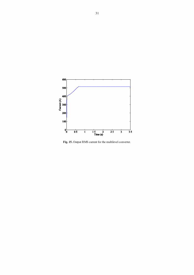
The output RMS current injected in the electric grid with the multilevel converter is shown in Fig. 15.
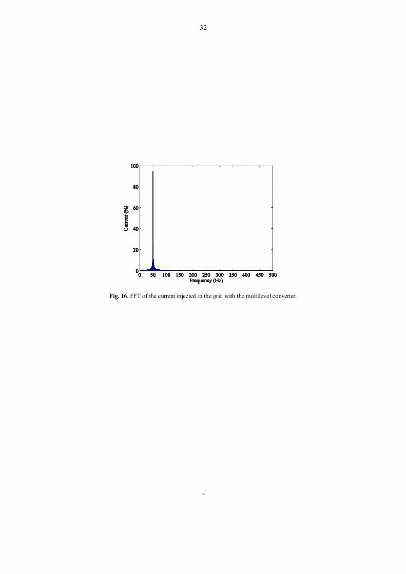
The harmonic behavior for the current injected in the electric grid with the multilevel converter,
computed by the FFT and the THD, is shown in Figs. 16 and 17, respectively.
"See Fig. 14 at the end of the manuscript".
"See Fig. 15 at the end of the manuscript".
"See Fig. 16 at the end of the manuscript".
"See Fig. 17 at the end of the manuscript".
Table 1 summarizes an overall comparison between the matrix and multilevel converters, regarding
the THD. The proposed wind energy system with the multilevel converter achieved the best performance.
Nevertheless, due to the new fractional-order control strategy proposed in this paper, the current THD
with either matrix or multilevel converter is lower than 5% limit imposed by IEEE-519 standard [34].
"See Table 1 at the end of the manuscript".
6. Conclusions
The increased wind power penetration leads to new technical challenges, dynamic stability and power
quality. The contributions of this paper are twofold. A new integrated model for the simulation of wind
energy systems, more realistic and accurate, is presented in this paper considering different power
converter topologies. Additionally, a new fractional-order control strategy is proposed for the variable-
speed operation of wind turbines with PMSG/full-power converter topology. The simulation results show

15
that the proposed fractional-order control strategy improves the performance of disturbance attenuation
and system robustness. Hence, the current THD with either matrix or multilevel converter is lower than
5% limit imposed by IEEE-519 standard, which is used as a guideline for comparison purposes.
References
[1] Ahmed NA, Miyatake M, Al-Othman AK. Power fluctuations suppression of stand-alone hybrid generation combining
solar photovoltaic/wind turbine and fuel cell systems. Energy Conv Manag 2008;49:2711–9.
[2] Estanqueiro A, Castro R, Flores P, Ricardo J, Pinto M, Rodrigues R, Peças Lopes J. How to prepare a power system for
15% wind energy penetration: the Portuguese case study. Wind Energy 2008;11:75–84.
[3] Ullah NR, Thiringer T. Variable speed wind turbines for power system stability enhancement. IEEE Trans Energy
Convers 2007;22:52–60.
[4] Carrasco JM, Franquelo LG, Bialasiewicz JT, Galvan E, Guisado RCP, Prats AM, Leon JI, Moreno-Alfonso N. Power-
electronic systems for the grid integration of renewable energy sources: A survey. IEEE Trans Ind Electron 2006;53:1002–
16.
[5] Baroudi JA, Dinavahi V, Knight AM. A review of power converter topologies for wind generators. Renew Energy
2007;32:2369–85.
[6] Li H, Chen Z. Overview of different wind generator systems and their comparisons. IET Renew Power Gener
2008;2:123–38.
[7] Hong YY, Lu SD, Chiou CS. MPPT for PM wind generator using gradient approximation. Energy Conv Manag
2009;50:82–9.
[8] Hansen AD, Michalke G. Modelling and control of variable-speed multi-pole permanent magnet synchronous generator
wind turbine. Wind Energy 2008;11:537–54.
[9] Tentzrakis ST, Papathanassiou SA. An investigation of the harmonic emissions of wind turbines. IEEE Trans Energy
Convers 2007;22:150–8.
[10] Wheeler PW, Clare JC, Apap M, Bradley KJ. Harmonic loss due to operation of induction machines from matrix
converters. IEEE Trans Ind Electron 2008;55:809–16.
[11] Wheeler PW, Rodríguez J, Clare JC, Empringham L, Weinstein A. Matrix converters: A technology review. IEEE
Trans Ind Electron 2002;49:276–88.
[12] Cardenas R, Peña R, Wheeler P, Clare J. Reactive power capability of WECS based on matrix converter. Electron Lett
2008;44:674–6.
[13] Jia S, Wang X, Tseng KJ. Matrix converters for wind energy systems. Proceedings of 2nd IEEE Conf Ind Electron
Appl 2007;488–94.
[14] Ceballos S, Pou J, Robles E, Gabiola I, Zaragoza J, Villate JL, Boroyevich D. Three-level converter topologies with
switch breakdown fault-tolerance capability. IEEE Trans Ind Electron 2008;55:982–95.
[15] Barros JD, Silva JF. Optimal predictive control of three-phase NPC multilevel converter for power quality applications.
IEEE Trans Ind Electron 2008;55;3670–81.
[16] Busquets-Monge S, Ortega JD, Bordonau J, Beristáin JA, Rocabert J. Closed-loop control of a three-phase neutral-
point-clamped inverter using an optimized virtual-vector-based pulsewidth modulation. IEEE Trans Ind Electron
2008;55;2061–71.
[17] Portillo RC, Prats MM, Leon JI, Sanchez JA, Carrasco JM, Galvan E, Franquelo LG. Modeling strategy for back-to-
back three-level converters applied to high-power wind turbines. IEEE Trans Ind Electron 2006;53;1483–91.
[18] Alepuz S, Busquets-Monge S, Bordonau J, Gago J, Gonzalez D, Balcells J. Interfacing renewable energy sources to the
utility grid using a three-level inverter. IEEE Trans Ind Electron 2006;53;1504–11.

16
[19] Rodriguez J, Lai J-S, Peng FZ. Multilevel inverters: A survey of topologies, controls, and applications. IEEE Trans Ind
Electron 2002;49;724–38.
[20] Eloy-Garcia J, Arnaltes S, Rodriguez-Amenedo JL. Extended direct power control for multilevel inverters including
DC link middle point voltage control. IET Electr Power Appl 2007;1;571–80.
[21] Slootweg JG, de Haan SWH, Polinder H, Kling WL. General model for representing variable speed wind turbines in
power system dynamics simulations. IEEE Trans. Power Syst. 2003;28:144–51.
[22] Conroy JF, Watson R. Low-voltage ride-through of a full converter wind turbine with permanent magnet generator. IET
Renew Power Gener 2007;1:182–9.
[23] Chinchilla M, Arnaltes S, Burgos JC. Control of permanent-magnet generators applied to variable-speed wind energy
systems connected to the grid. IEEE Trans Energy Convers 2006;21:130–5.
[24] Senjyu T, Tamaki S, Urasaki N, Uezato K. Wind velocity and position sensorless operation for PMSG wind generator.
Proceedings of 5th PEDC, 2003;787–92.
[25] Barakati SM, Aplevich JD, Kazerani M. Controller design for a wind turbine system including a matrix converter.
Proceedings 2007 IEEE PES GM, 2007.
[26] Pinto S, Silva J. Sliding mode direct control of matrix converters. IET Electr Power Appl 2007;1:439–48.
[27] Melício R, Mendes VMF, Catalão JPS. Two-level and multilevel converters for wind energy systems: a comparative
study. Proceedings of the 13th EPE-PEMC, 2008;1682–7.
[28] Melício R, Mendes VMF, Catalão JPS. Evaluating power quality in wind power generation systems with two-level and
multi-level converters. Proceedings of the 6th MedPower Conf., 2008.
[29] Barros JD, Silva JF. Optimal predictive control of three-phase NPC multilevel converter for power quality applications.
IEEE Trans Ind Electron 2008;55;3670–81.
[30] Podlubny I. Fractional-order systems and PI-lambda-D-mu-controllers. IEEE Trans Autom Control 1999;44:208–214.
[31] Li W, Hori Y, Peng FZ. Vibration suppression using single neuron-based PI fuzzy controller and fractional-order
disturbance observer. IEEE Trans Ind Electron 2007;54;117–26.
[32] Calderón AJ, Vinagre BM, Feliu V. Fractional order control strategies for power electronic buck converters. Signal
Processing 2006;86:2803–19.
[33] Beltran B, Ahmed-Ali T, Benbouzid MEH. Sliding mode power control of variable-speed wind energy conversion
systems. IEEE Trans Energy Convers 2008;23:551–8.
[34] IEEE Guide for Harmonic Control and Reactive Compensation of Static Power Converters, IEEE Standard 519-1992.

17
Figure captions
Fig. 1. Power coefficient as a function of the tip speed ratio, parameterized in function of the pitch angle.

18
Fig. 2. Configuration of the two-mass drive train model.

19
Fig. 3. Wind energy system with matrix converter.

20
Fig. 4. Wind energy system with multilevel converter.

21
Fig. 5. Output voltage vectors for the matrix converter.
22
Fig. 6. Input current vectors for the matrix converter.

23
Fig. 7. Output voltage vectors for the multilevel converter.

24
Fig. 8. Mechanical, electric and accelerating power.

25
Fig. 9. Harmonic behavior for the mechanical power of the wind turbine.

26
Fig. 10. Output current for the matrix converter.

27
Fig. 11. Output RMS current for the matrix converter.

28
Fig. 12. FFT of the current injected in the grid with the matrix converter.

29
Fig. 13. THD of the current injected in the grid with the matrix converter.

30
Fig. 14. Output current for the multilevel converter.
31
Fig. 15. Output RMS current for the multilevel converter.
32
Fig. 16. FFT of the current injected in the grid with the multilevel converter.
~

33
Fig. 17. THD of the current injected in the grid with the multilevel converter.

34
Tables
Table 1
THD of the current injected in the grid
Power converter topology THD (%)
Matrix 2.13
Multilevel 0.10