Embed Size (px)
Citation preview
Vol.:(0123456789)1 3
Production Engineering https://doi.org/10.1007/s11740-018-0796-1
COMPUTER AIDED ENGINEERING
Fracture mechanics based assessment of manufacturing defects laying at the edge of CFRP-metal bondlines
Konstantinos Anyfantis1 · Panagiotis Stavropoulos1,2 · George Chryssolouris1
Received: 24 November 2017 / Accepted: 11 January 2018 © The Author(s) 2018. This article is an open access publication
AbstractThis study presents a simplified approach for the evaluation of the bond line load capacity of CFRP-metal hybrid structural parts, bearing manufacturing defects. The proposed approach overcomes the need of modeling debonding with the use of advanced non-linear FEM, and relies on the post-processing of the stress and strain fields developed at the free edges of the hybrid material (critical locations in the presence of manufacturing defects), with the use of interfacial fracture mechanics. First, the mathematics, related to the analytical calculation of the bi-material fracture toughness, is presented and applied to a simple CFRP-metal geometry. Corresponding FE simulations are performed and the J-integral is employed for the numerical calculation of the SERR magnitude of different defect sizes. In the following, a simplified calculation of the SERR magnitude that sources from FE results and implemented in geometries modeled by shell finite elements that typically require advanced modeling techniques, is provided for the simulation of the de-bonding process.
Keywords Multi-materials · Hybrid CFRP-metal · Defects · Structural design
1 Introduction
The global demand for the minimization of the environ-mental impact on automotive and aerospace vehicles con-tinuously pose requirements for a lightweight design of the associated structural assemblies. The geometry of compo-nents conventionally produced by metallic materials has already achieved a high degree of optimization, in terms of weight savings, even with the introduction of modern stronger alloys. A solution to achieving higher mass reduc-tion is through the replacement of metals with carbon fiber reinforced polymer (CFRP) composites that have superior strength-to-weight and stiffness-to-weight mechanical prop-erties. Typical examples are those found in the aerospace industry with Boeing 787 [1] and Airbus A350 XWB [2] having 43 and 52% of the metallic structure constructed by
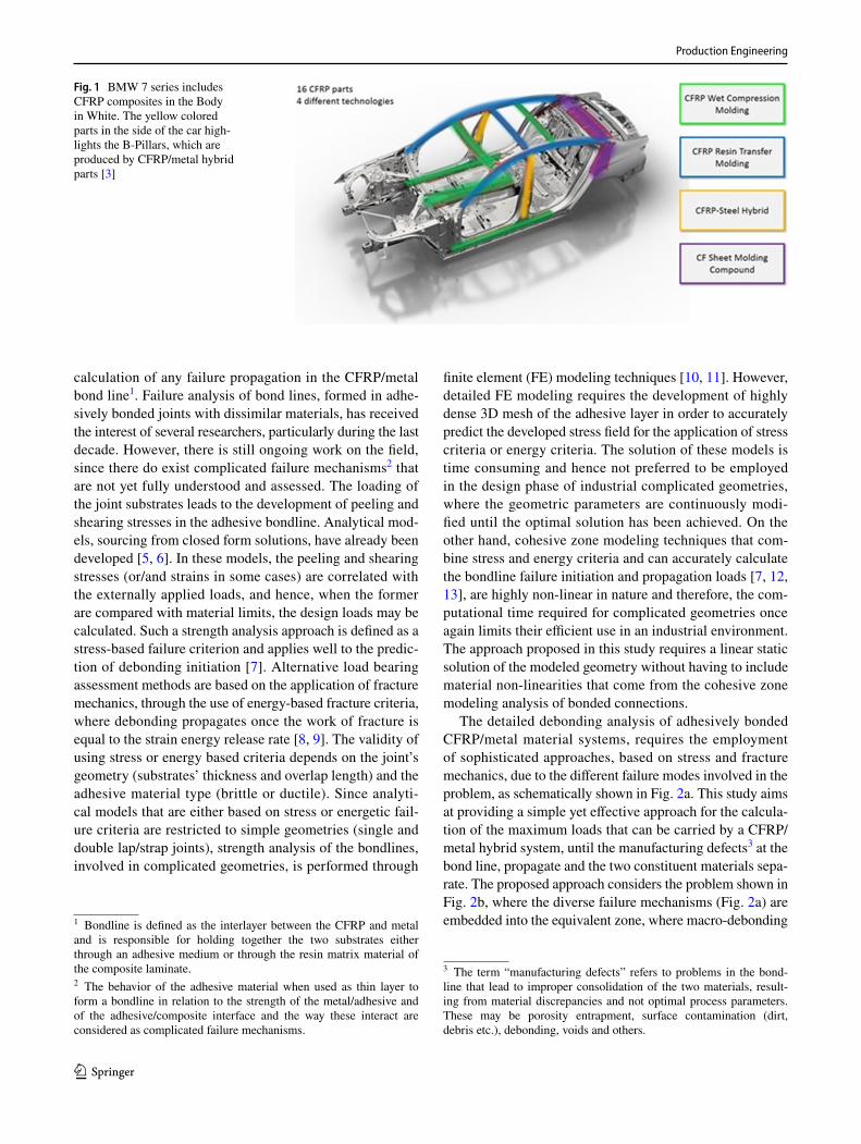
composite materials, respectively. In the automotive sec-tor, the BMW 7 series has replaced several metallic com-ponents with composite materials [3], as shown in Fig. 1. However, there are certainly components whose imposed design requirements are not met if the metal is fully replaced by composites. A good example is that of the B-Pillar com-ponent (side part of the Body In White for protecting the passengers in the case of a side collision), which if entirely made of composites, then its crashworthiness is not equiva-lent to the respective metallic one. A promising solution is by using a hybrid CFRP/metal combination (see Fig. 1), where the CFRP layers are adhesively bonded onto selected parts of the metallic component.
Besides research and development carried out in produc-tion technologies that will enable the automated manufac-turing of CFRP/metal hybrid parts, it is of high importance that specialized design methods and tools be developed. Recently, the authors have published relevant work [4] on the design of hybrid parts by employing optimization techniques for the calculation of the design variables (num-ber of layers, layer orientation, reduced metal thickness), where in the proposed formulation it is assumed that the bond area remains intact and only failure in the metal and composite has been considered. This study focuses on devel-oping a simplified yet effective modeling technique for the
* George Chryssolouris [email protected]
1 Laboratory for Manufacturing Systems and Automation, Department of Mechanical Engineering and Aeronautics, University of Patras, 26500 Patras, Greece
2 Department of Aeronautical Studies, Hellenic Air Force Academy, Dekelia Air-Force Base, TGA , 1010 Athens, Greece
Production Engineering
1 3
calculation of any failure propagation in the CFRP/metal bond line1. Failure analysis of bond lines, formed in adhe-sively bonded joints with dissimilar materials, has received the interest of several researchers, particularly during the last decade. However, there is still ongoing work on the field, since there do exist complicated failure mechanisms2 that are not yet fully understood and assessed. The loading of the joint substrates leads to the development of peeling and shearing stresses in the adhesive bondline. Analytical mod-els, sourcing from closed form solutions, have already been developed [5, 6]. In these models, the peeling and shearing stresses (or/and strains in some cases) are correlated with the externally applied loads, and hence, when the former are compared with material limits, the design loads may be calculated. Such a strength analysis approach is defined as a stress-based failure criterion and applies well to the predic-tion of debonding initiation [7]. Alternative load bearing assessment methods are based on the application of fracture mechanics, through the use of energy-based fracture criteria, where debonding propagates once the work of fracture is equal to the strain energy release rate [8, 9]. The validity of using stress or energy based criteria depends on the joint’s geometry (substrates’ thickness and overlap length) and the adhesive material type (brittle or ductile). Since analyti-cal models that are either based on stress or energetic fail-ure criteria are restricted to simple geometries (single and double lap/strap joints), strength analysis of the bondlines, involved in complicated geometries, is performed through
finite element (FE) modeling techniques [10, 11]. However, detailed FE modeling requires the development of highly dense 3D mesh of the adhesive layer in order to accurately predict the developed stress field for the application of stress criteria or energy criteria. The solution of these models is time consuming and hence not preferred to be employed in the design phase of industrial complicated geometries, where the geometric parameters are continuously modi-fied until the optimal solution has been achieved. On the other hand, cohesive zone modeling techniques that com-bine stress and energy criteria and can accurately calculate the bondline failure initiation and propagation loads [7, 12, 13], are highly non-linear in nature and therefore, the com-putational time required for complicated geometries once again limits their efficient use in an industrial environment. The approach proposed in this study requires a linear static solution of the modeled geometry without having to include material non-linearities that come from the cohesive zone modeling analysis of bonded connections.
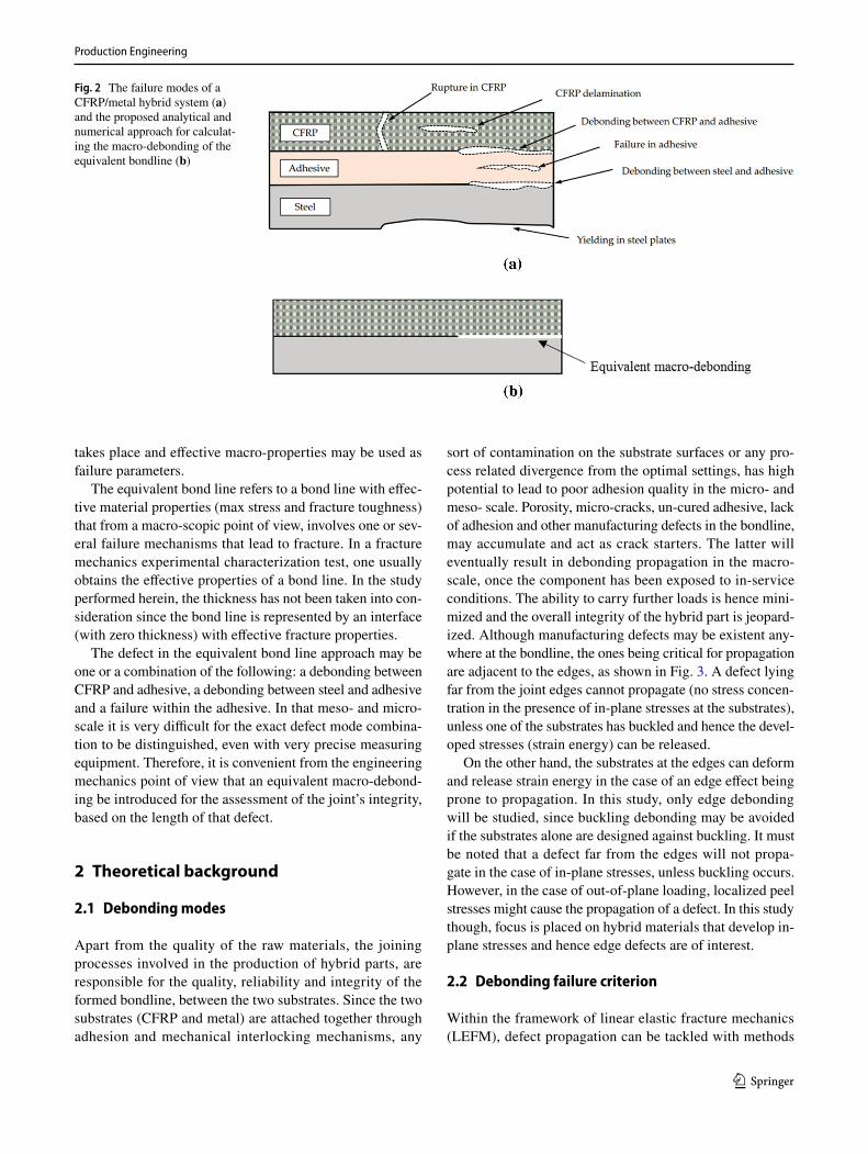
The detailed debonding analysis of adhesively bonded CFRP/metal material systems, requires the employment of sophisticated approaches, based on stress and fracture mechanics, due to the different failure modes involved in the problem, as schematically shown in Fig. 2a. This study aims at providing a simple yet effective approach for the calcula-tion of the maximum loads that can be carried by a CFRP/metal hybrid system, until the manufacturing defects3 at the bond line, propagate and the two constituent materials sepa-rate. The proposed approach considers the problem shown in Fig. 2b, where the diverse failure mechanisms (Fig. 2a) are embedded into the equivalent zone, where macro-debonding
Fig. 1 BMW 7 series includes CFRP composites in the Body in White. The yellow colored parts in the side of the car high-lights the B-Pillars, which are produced by CFRP/metal hybrid parts [3]
1 Bondline is defined as the interlayer between the CFRP and metal and is responsible for holding together the two substrates either through an adhesive medium or through the resin matrix material of the composite laminate.2 The behavior of the adhesive material when used as thin layer to form a bondline in relation to the strength of the metal/adhesive and of the adhesive/composite interface and the way these interact are considered as complicated failure mechanisms.
3 The term “manufacturing defects” refers to problems in the bond-line that lead to improper consolidation of the two materials, result-ing from material discrepancies and not optimal process parameters. These may be porosity entrapment, surface contamination (dirt, debris etc.), debonding, voids and others.
Production Engineering
1 3
takes place and effective macro-properties may be used as failure parameters.
The equivalent bond line refers to a bond line with effec-tive material properties (max stress and fracture toughness) that from a macro-scopic point of view, involves one or sev-eral failure mechanisms that lead to fracture. In a fracture mechanics experimental characterization test, one usually obtains the effective properties of a bond line. In the study performed herein, the thickness has not been taken into con-sideration since the bond line is represented by an interface (with zero thickness) with effective fracture properties.
The defect in the equivalent bond line approach may be one or a combination of the following: a debonding between CFRP and adhesive, a debonding between steel and adhesive and a failure within the adhesive. In that meso- and micro-scale it is very difficult for the exact defect mode combina-tion to be distinguished, even with very precise measuring equipment. Therefore, it is convenient from the engineering mechanics point of view that an equivalent macro-debond-ing be introduced for the assessment of the joint’s integrity, based on the length of that defect.
2 Theoretical background
2.1 Debonding modes
Apart from the quality of the raw materials, the joining processes involved in the production of hybrid parts, are responsible for the quality, reliability and integrity of the formed bondline, between the two substrates. Since the two substrates (CFRP and metal) are attached together through adhesion and mechanical interlocking mechanisms, any
sort of contamination on the substrate surfaces or any pro-cess related divergence from the optimal settings, has high potential to lead to poor adhesion quality in the micro- and meso- scale. Porosity, micro-cracks, un-cured adhesive, lack of adhesion and other manufacturing defects in the bondline, may accumulate and act as crack starters. The latter will eventually result in debonding propagation in the macro-scale, once the component has been exposed to in-service conditions. The ability to carry further loads is hence mini-mized and the overall integrity of the hybrid part is jeopard-ized. Although manufacturing defects may be existent any-where at the bondline, the ones being critical for propagation are adjacent to the edges, as shown in Fig. 3. A defect lying far from the joint edges cannot propagate (no stress concen-tration in the presence of in-plane stresses at the substrates), unless one of the substrates has buckled and hence the devel-oped stresses (strain energy) can be released.
On the other hand, the substrates at the edges can deform and release strain energy in the case of an edge effect being prone to propagation. In this study, only edge debonding will be studied, since buckling debonding may be avoided if the substrates alone are designed against buckling. It must be noted that a defect far from the edges will not propa-gate in the case of in-plane stresses, unless buckling occurs. However, in the case of out-of-plane loading, localized peel stresses might cause the propagation of a defect. In this study though, focus is placed on hybrid materials that develop in-plane stresses and hence edge defects are of interest.
2.2 Debonding failure criterion
Within the framework of linear elastic fracture mechanics (LEFM), defect propagation can be tackled with methods
Fig. 2 The failure modes of a CFRP/metal hybrid system (a) and the proposed analytical and numerical approach for calculat-ing the macro-debonding of the equivalent bondline (b)

Production Engineering
1 3
based on the energy approach to failure. When external loading is applied to the hybrid component, containing an initial defect of size α0, then the involved substrates deform, develop stresses and therefore store a certain amount of strain energy, U (units in Joules). The stresses are being transferred from one substrate to the other through the bon-dline, which load bearing capacity is directly related to the work of fracture or fracture toughness Gc (units in J/m2 or N/mm). This magnitude is experimentally measured, through specialized fracture tests (three- or four-point bending, dou-ble cantilever beam, mixed-mode tests, etc) in laboratory conditions. According to the energetic approach to failure, a manufacturing defect in the bondline will not propagate until the strain energy release rate (SERR), G, given by
is equal to or becomes higher than the macro-scale frac-ture toughness of the bondline Gc. Hence, the following frac-ture criterion can be used for the load bearing assessment of bondlines:
Experimental techniques have not yet been standardized for gauging the fracture toughness of bondlines, formed in multi-material systems, despite this field undergoing impor-tant research. Tests such as the end notch flexure (ENF), the single leg bending (SLB) and double cantilever beam loaded with uneven bending moments (DCB-UBM) have been used in research studies to gauge the Mode II fracture toughness of bondlines, formed between composites and metals [14].
The key advantage of this criterion (Eq. 2) is that it does not consider the complex stress field in the vicinity of the crack tip but only the energy stored in the material by the remote elastic stresses. Therefore, it is practical to be used
(1)G =�U
��,
(2)G ⩾ Gc
in the design phase of complicated geometries, as it will be shown in later sections.
2.3 Debonding of a hybrid beam
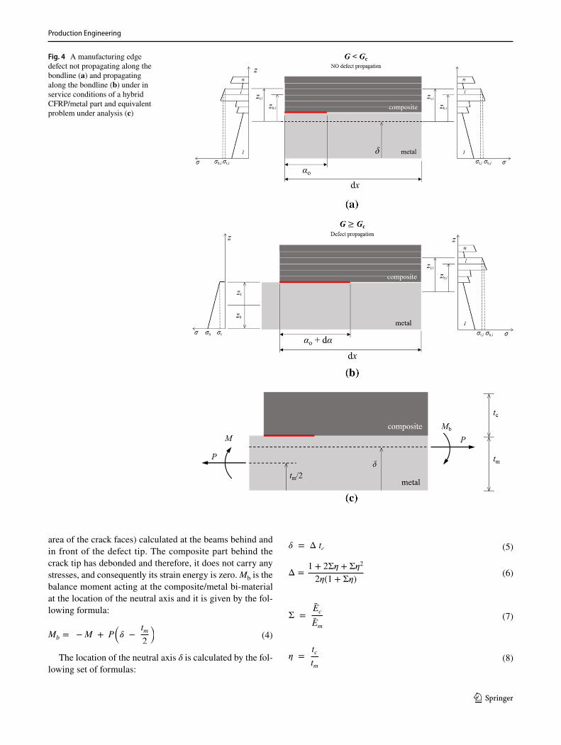
This section involves the load bearing assessment of a bon-dline formed in a CFRP/metal 1D beam geometry that is subjected to in-service conditions and contains an edge manufacturing defect of length α0. An infinitesimal element dx, in the vicinity of the edge, is taken for analysis, as shown in Fig. 4a. Assuming that the initial crack length is very small compared to the length dx, then the developed stress field is uniform along the entire length of the element and its magnitude and through-the-thickness distribution do not allow the development of high enough strain energy for the defect to propagate (G < Gc). Magnification of the stress pro-file will enable the defect to propagate (G ≥ Gc) and hence the debonding will interrupt the load transfer from one sub-strate to the other, since the part of the composite substrate, behind the crack tip, cannot absorb further load (Fig. 4b). Considering the composite layers as one isotropic layer with equivalent elastic constants, the problem shown in Fig. 4c is solved in [15] and the obtained formula for the calculation of the SERR magnitude of the bi-layer is provided below:
This formula yields Gss, which refers to the constant rate of energy being released, during the steady state debonding propagation. P is the resultant axial force and M is the result-ant bending moment acting on the metal substrate, as shown in Fig. 4c. This formula physically expresses the difference in the strain energy density (normalized strain energy to the
(3)Gss =1
2Em
(
P2
tm+12
M 2
t 3m
−P 2
A tc−
M 2b
It 3c
)
Fig. 3 Possible modes responsi-ble for debonding propagation
Production Engineering
1 3
area of the crack faces) calculated at the beams behind and in front of the defect tip. The composite part behind the crack tip has debonded and therefore, it does not carry any stresses, and consequently its strain energy is zero. Mb is the balance moment acting at the composite/metal bi-material at the location of the neutral axis and it is given by the fol-lowing formula:
The location of the neutral axis δ is calculated by the fol-lowing set of formulas:
(4)Mb = −M + P
(
� −tm
2
)
(5)� = Δ tc
(6)Δ =1 + 2Σ� + Σ�2
2�(1 + Σ�)
(7)Σ =Ec
Em
(8)� =tc
tm
Fig. 4 A manufacturing edge defect not propagating along the bondline (a) and propagating along the bondline (b) under in service conditions of a hybrid CFRP/metal part and equivalent problem under analysis (c)

Production Engineering
1 3
Magnitudes Ec and Em correspond to the effective plane stress Young modulus of the composite and metal layers, respectively, and are given by:
Ec =Ec
1 − v2c
and Em =Em
1 − v2m
, where, Ec, Em and vc, vm are
the substrate Young moduli and Poisson’s ratio, respectively.
The normalized axial stiffness A and bending stiffness I are given by the following formulas:
Equation (3), includes only geometric and material parameters alongside with the loading magnitudes, exclud-ing the defect size α0. This feature is advantageous for the assessment of the bondline’s load capacity within the design process of hybrid parts, since the exact location, density and size of the manufacturing defects are unknown parameters. Additionally, the provided formula considers only the thick-ness of the associated substrates and not any length related magnitudes, which in turn, result in the steady-state energy release rate Gss, which refers to the constant rate of energy being released during the steady state debonding propaga-tion. As it will be shown in the next section, there does exist a certain defect size beyond which the SERR magnitude becomes constant, Gss.
2.4 Effect of defect’s length
In order to evaluate the validity of Eq. 3 in hybrid parts with defects of finite length, numerical simulations based on finite element methods have been performed. The simple hybrid geometry shown in Fig. 5 has been considered in order for the effect of the defect’s length α0 on the SERR magnitude to be evaluated. The length of the metal lm is equal to 200 mm and the length of the composite patch lc is equal to 100 mm. The metal thickness tm is 2 mm. The composite consists of eight layers with a stacking sequence [0/90/45/-45]s and with a ply thickness tl equal to 0.2 mm.
(9)A =1
�+Σ
(10)
I = Σ
[
(
Δ −1
�
)2
−
(
Δ −1
�
)
+1
3
]
+Δ
�
(
Δ −1
�
)
+1
3�3
The total composite thickness tc is equal to 8 × 0.2 = 1.6 mm. The width of the hybrid system (normal to the cross sec-tional view of Fig. 5) is taken as equal to 100 mm. In order for Eq. 3 to be applied to the considered geometry that is for-mulated according to the 1D beam theory, the effective stiff-ness of the composite layers has been calculated according to the classical theory of laminated composites. Hence, the effective Young modulus of the composite stack in x direc-tion is equal to 73.9 GPa, given the ply elastic constants, i.e., E1 = 178 GPa, E2 = 10 GPa, G12 = 4.55 GPa, v12 = 0.3 and v21 = 0.02. The metal substrate was modeled with a Young modulus of 210 GPa and a Poisson’s ratio of 0.3. Although only an axial load P of 50 kN has been applied to the metal free edges, the hybrid area (CFRP/metal overlap) develops secondary bending stresses on top of the axial ones. This effect is due to the fact that the load application point on the metal (tm/2) is different from the location of the neutral axis of the hybrid part (δ), as it is schematically shown in Fig. 4c. The geometry has been modeled in ANSYS com-mercial FE software in both a 2D and a 3D space with linear quadrilateral finite elements, as shown in Fig. 6. The left end of the metal has been considered as being simply supported (constrained displacement at x and y direction, rotation is permitted) and the load is applied to the right end of the metal. Five models have been generated and solved as linear static by varying the length of the defect (α0 = 0.2, 0.3, 0.4, 0.5, 1 and 3 mm) and keeping the applied load equal for all cases. A quite dense mesh has been used in all models (2D and 3D) in the vicinity of the defect tip in order for the complex stress field to be accurately captured. The SERR magnitude has been numerically calculated through the use of the J-integral approach, which is a pre-coded feature in ANSYS program.
Figure 7 presents the effect of the defect’s size, lying at the edge of the bondline, with respect to the SERR magnitude. The numerically calculated G values are normalized by the Gss magnitude as calculated in Eq. 3 and are equal to 0.084 N/mm (84 J/m2). It is clear that SERR is increasing together with the defect’s size, in a progressive (non-linear) manner, until it reaches a pla-teau level, where it remains constant and it is not further influenced by longer defects. This plateau corresponds to the steady state SERR condition. For a given load case,
Fig. 5 Simple hybrid geometry considered for load bearing assessment

Production Engineering
1 3
debonding propagation will occur only under the exist-ence of a defect, with a size equal to or greater than a critical size, where in the considered example it is equal to approximately 1 mm. Hence, defects of smaller size will not propagate, since there is not enough strain energy stored into the substrates (< Gss) to be released, accord-ing to the energetic criterion, described by Eq. 2. The existence of a relatively minor defect at the edge will
not cause any noticeable stress redistribution that would allow energy release. As the defect’s size increases, the stresses redistribute and part of the edge material, being on the upper side behind the crack front gets unstressed, in a way that strain energy may be released. The analyti-cal solution does not model this transition and considers only a fully unstressed material behind the defect front and hence, it provides the steady state SERR magnitude.
Fig. 6 Simple geometry used for evaluating the effect of the defect’s length to the SERR magnitude and modeled in a 2D FE space (a) and 3D FE space (b). A magnification of the meshed region around the defect tip (for 2D and 3D models) is presented in sub-figure (c)
(a)
(b)
(c)
X
Y
Z
X
Y
Z
Fig. 7 Effect of the defect length on the SERR magnitude as calculated from 2D finite ele-ment analysis
0.80
0.84
0.88
0.92
0.96
1.00
1.04
0 0.5 1 1.5 2 2.5 3
G/ G
ss
Defect length - α0 (mm)
Steady state fracture Gss
Production Engineering
1 3
On the other hand, a detailed numerical model is able to capture this transition in the stress relief process towards the steady state.
The analytical method for evaluation Gss is also appli-cable to other material/thickness combinations, as long as the problem remains one dimensional, where axial load-ing and bending moment are applied in one direction. In case of in-plane load combinations, then the analytical formula has to be re-worked. On the other hand, numeri-cal simulations, based on FEA, may be used in complex loading conditions by varying the size of a defect, until the plateau level has been found.
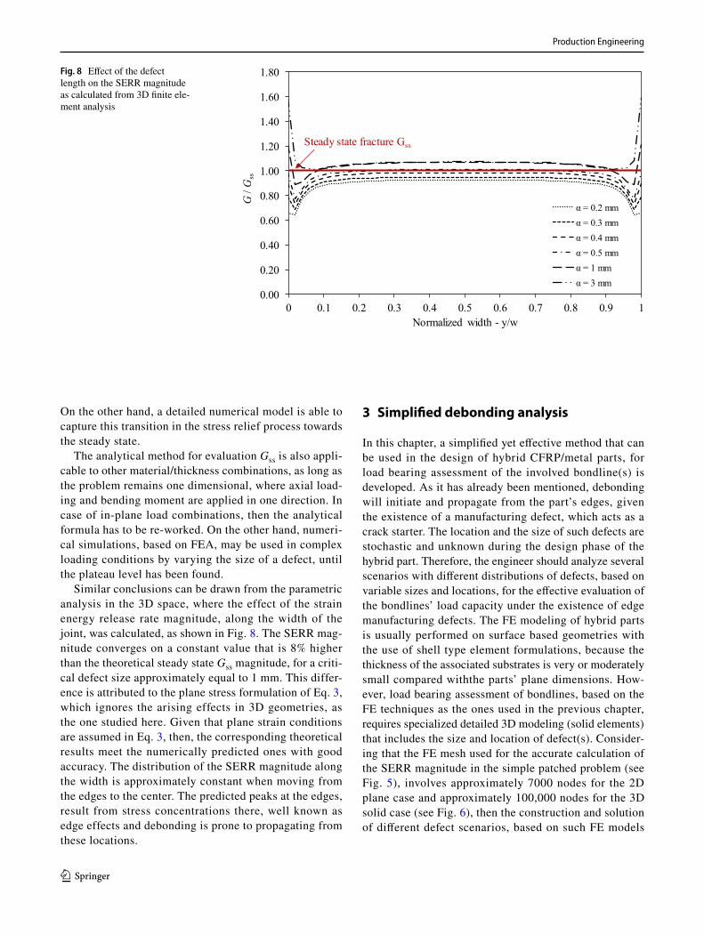
Similar conclusions can be drawn from the parametric analysis in the 3D space, where the effect of the strain energy release rate magnitude, along the width of the joint, was calculated, as shown in Fig. 8. The SERR mag-nitude converges on a constant value that is 8% higher than the theoretical steady state Gss magnitude, for a criti-cal defect size approximately equal to 1 mm. This differ-ence is attributed to the plane stress formulation of Eq. 3, which ignores the arising effects in 3D geometries, as the one studied here. Given that plane strain conditions are assumed in Eq. 3, then, the corresponding theoretical results meet the numerically predicted ones with good accuracy. The distribution of the SERR magnitude along the width is approximately constant when moving from the edges to the center. The predicted peaks at the edges, result from stress concentrations there, well known as edge effects and debonding is prone to propagating from these locations.
3 Simplified debonding analysis
In this chapter, a simplified yet effective method that can be used in the design of hybrid CFRP/metal parts, for load bearing assessment of the involved bondline(s) is developed. As it has already been mentioned, debonding will initiate and propagate from the part’s edges, given the existence of a manufacturing defect, which acts as a crack starter. The location and the size of such defects are stochastic and unknown during the design phase of the hybrid part. Therefore, the engineer should analyze several scenarios with different distributions of defects, based on variable sizes and locations, for the effective evaluation of the bondlines’ load capacity under the existence of edge manufacturing defects. The FE modeling of hybrid parts is usually performed on surface based geometries with the use of shell type element formulations, because the thickness of the associated substrates is very or moderately small compared withthe parts’ plane dimensions. How-ever, load bearing assessment of bondlines, based on the FE techniques as the ones used in the previous chapter, requires specialized detailed 3D modeling (solid elements) that includes the size and location of defect(s). Consider-ing that the FE mesh used for the accurate calculation of the SERR magnitude in the simple patched problem (see Fig. 5), involves approximately 7000 nodes for the 2D plane case and approximately 100,000 nodes for the 3D solid case (see Fig. 6), then the construction and solution of different defect scenarios, based on such FE models
Fig. 8 Effect of the defect length on the SERR magnitude as calculated from 3D finite ele-ment analysis
0.00
0.20
0.40
0.60
0.80
1.00
1.20
1.40
1.60
1.80
0 0.1 0.2 0.3 0.4 0.5 0.6 0.7 0.8 0.9 1
G/ G
ss
Normalized width - y/w
α = 0.2 mmα = 0.3 mmα = 0.4 mmα = 0.5 mmα = 1 mmα = 3 mm
Steady state fracture Gss
Production Engineering
1 3
is time and CPU inefficient for complicated geometries. In order to overcome these issues, an efficient method is proposed below for the calculation of the SERR magnitude in hybrid parts of complex geometries.
3.1 Method description
The proposed method takes advantage of the fact that the driv-ing force of a bondline fracture, i.e., the steady state strain energy release rate, does not depend on the defect’s size for values equal to or higher than a critical size level. It has already been shown that for a given load case, defects of a smaller size than the critical ones will not propagate, unless the loads are magnified or unexpected in-service loads occur. The goal is that magnitude Gss be calculated at the material points, located around the bondline’s edges of a hybrid part, mod-eled in FE environment with the use of shell elements. In such modeling techniques, it is assumed that the material develops in-plane stresses, as illustrated in Fig. 4a, whereas the out-of-plane stresses remain at low levels, hence are ignored. In this regard, the strain energy may be normalized by the element’s area, which leads to the strain energy density U with units of energy/area (J/m2) that compares with the units of fracture toughness magnitude. The difference between the strain energy density ahead of the defect tip and behind the crack tip yields the steady state SERR magnitude as given by the following formula:
The strain energy density is given by the formula:
(11)G =𝜕U
𝜕𝛼→ SERR = Uahead of defeat tip − Ubehind defeat tip
(12)U =1
2 ∫ 𝜎 ∶ 𝜀 dz
where, σ and ε are the in-plane stress and strain tensors in a Cartesian frame on the surface of an element,
Due to tensor’s symmetry, σ12 is equal to σ21 and ε12 is equal to ε21. Since the post-processing results of the finite element solution provide the stress and strain tensors for each defined layer of each element, then by approximating the integral of Eq. 12 and substituting with Eq. 13, the fol-lowing equation is generated:
where the summation runs through the total number n of the associated shell element layers.
Stress and strain components are calculated at the inte-gration points of the finite element mesh. Quadratic shell elements, with one in-plane integration point, located at the center of the element (following Gauss numerical integra-tion), are well known for their accurate prediction of the developed stress field. The through thickness stress variation is considered as linear and calculated through trapezoidal integration rules.
3.2 Method validation and benchmarking
The above mentioned approach, which is modeled with quadratic (8-node) shell elements, has been applied to the geometry presented in Fig. 5. A parametric analysis has been conducted by varying the in-plane dimensions of the shell elements attached to the bondline edge, i.e., 0.5 × 0.5, 1 × 1 and 5 × 5 m2. Following the solution of the FE models, Eq. 11 was applied to the stress–strain results at the row of
(13)� =
[
�11 �12�21 �22
]
, � =
[
�11 �12�21 �22
]
(14)
U =1
2
n∑
i=1
(
∫ 𝜎11𝜀11dz + 2 ∫ 𝜎12𝜀12dz + ∫ 𝜎22𝜀22dz
)
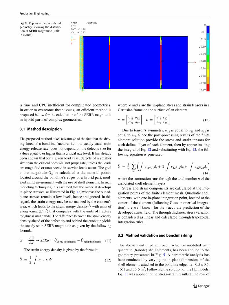
Fig. 9 Top view the considered geometry, showing the distribu-tion of SERR magnitude (units in N/mm)
MN
MX
11 X
Y
Z
0
.01
.019
.029
.039
.048
.058
.068
.078
.087
SERR (NOAVG)TOPDMX =1.98SMX =.087UROTF

Production Engineering
1 3
elements ahead and behind the bondline edge via Eq. 14. Figure 9 presents the distribution of the SERR magnitude to the modeled geometry with element dimensions 1 × 1 mm2. It can be seen that the maximum calculated SERR value is 0.087 N/mm that differs only by 3.4% from the analytical steady state magnitude Gss obtained by Eq. 3, i.e., 0.084 N/mm. Figure 10 presents the results of the parametric anal-ysis, in terms of the distribution of the SERR magnitude along the width of the hybrid system. It is evident that there is no important influence of the element dimensions on the SERR magnitude and the results show that the proposed method calculates with great accuracy the analytical steady state energy release rate magnitude. The extent of defect size comprising the shell element model is directly related to the critical defect size and the shell element size. Hence, the designer has to be aware of the critical defect size in order to mesh the surface geometry with shell elements of accu-rate dimensions. Two dimensional FE models with the given material and thickness combinations may be used prior to shell modeling.
4 Conclusions
A simplified method has been proposed for the evaluation of the criticality of manufacturing defects, lying on the bon-dline, on the structural integrity of the hybrid composite/metal systems. A simple patched geometry that enables the application of an analytical equation for the calculation of the energy release rate, has been selected for benchmark-ing purposes. Finite element simulations have shown that there does exist a critical defect size that will propagate once the SERR magnitude is equal to the analytically calculated
steady-state release rate. Smaller defects than this critical size will not propagate under the design load case. The pro-posed method is a post calculation tool that when applied to FE simulation results, the driving force for defect propaga-tion, i.e., the SERR magnitude can be calculated with high accuracy. The validity of the proposed method is yet to be evaluated in complex geometries under the existence of complicated stress fields and diverse load cases.
Acknowledgements This work is under the framework of EU Project Communion. This project has received funding from the European Union’s Horizon 2020 research and innovation programme under grant agreement no. 680567.
Open Access This article is distributed under the terms of the Creative Commons Attribution 4.0 International License (http://creativecom-mons.org/licenses/by/4.0/), which permits unrestricted use, distribu-tion, and reproduction in any medium, provided you give appropriate credit to the original author(s) and the source, provide a link to the Creative Commons license, and indicate if changes were made.
References
1. Ahmad F, Hong JW, Choi HS, Park MK (2016) Hygro effects on the low-velocity impact behavior of unidirectional CFRP compos-ite plates for aircraft applications. Compos Struct 135:276–285
Fig. 10 Effect of the element dimensions to the calculated SERR magnitude through the proposed approach
Production Engineering
1 3
2. Information found at http://scribol.com/technology/aviation/airbus-a350-composites-on-trial-part-i/. Accessed Jan 2018
3. Information found at http://www.compositesworld.com/articles/is-the-bmw-7-series-the-future-of-autocomposites. Accessed Jan 2018
4. Anyfantis K, Foteinopoulos P, Stavropoulos P (2017) Design for manufacturing of multi-material mechanical parts: a computa-tional based approach, 1st Cirp Conference on Composite Materi-als Parts Manufacturing, cirp-ccmpm2017. Proc CIRP 66:22–26
5. Da Silva LF, das Neves PJ, Adams RD, Spelt JK (2009) Analytical models of adhesively bonded joints—Part I: literature survey. Int J Adhes Adhes 29:319–330
6. Da Silva LF, das Neves PJ, Adams RD, Wang A, Spelt JK (2009) Analytical models of adhesively bonded joints—Part II: compara-tive study. Int J Adhes Adhes 29:331–341
7. Anyfantis K (2014) On the failure analysis of bondlines: stress or energy based fracture criteria? Eng Fract Mech 126:108–125
8. Colombi P (2006) Reinforcement delamination of metallic beams strengthened by FRP strips: fracture mechanics based approach. Eng Fract Mech 73:1980–1995
9. Lenwari A, Thepchatri T, Watanabe E (2002) Prediction of pre-mature separation of bonded CFRP plates from strengthened steel beams using a fracture criterio. Struct Eng Mech 14:565–574
10. Vallée T, Correia JR, Keller T (2010) Optimum thickness of joints made of GFPR pultruted adherents and polyurethane adhesive. Compos Struct 92:2102–2108
11. Zhang Y, Vassilopoulos PA, Keller T (2010) Mode I and II frac-ture behaviour of adhesively-bonded pultruted composite joints. Eng Fract Mech 77:128–143
12. Campilho RDSG., de Moura MFSF., Pinto AMG, Morais JJL, Domingues JJMS (2009) Modelling the tensile fracture behaviour of CFRP scarf repairs. Compos Part B 40:149–157
13. Campilho RDSG., de Moura MFSF., Ramantani DA, Morais JJL, Domingues JJMS. (2009) Tensile behaviour of three-dimensional carbon-epoxy adhesively bonded single- and double-strap repairs. Int J Adhes Adhes 29:678–686
14. Anyfantis KN (2016) Composite to metal. In: Wahab MA (ed) Joining composites via adhesives: theory and applications, vol 5. DEStech Publications, Inc., Lancaster
15. Suo Z, Hutchinson JW (1990) Interface crack between two elastic layers. Int J Fract 43:1–18