Embed Size (px)
Citation preview

framework for MPIS-Based Confrol of Optical SDti/SONET Networks
Greg Bernstein, Ciena Corporation Eric Mannie, Ebone
Vishal Sharma, Metanoia, Inc.
Abstract The suite of protocols that defines Multi-Protocol Label Switching is in the process of enhancement to generalize i ts applicability to the control of optical networks. One area of prime consideration is to use these eneralized MPLS protocols in upgrading the control plane of optical transport netwok This article describes those extensions to MPLS directed toward controlling SDH/SONET networks. SDH/SONET networks are ideal candidates for this process since they possess a rich multiplex structure, and a variety of protection/restoration options are well defined and widely deployed. Wediscuss theextensions toMPLS routing protocols to disseminate information needed for transport path computation and network operations, and the extensions to MPLS label distribution protocols needed for provisioning of transport circuits.
D H [l] /SONET [ 2 ] is the predominant optical networking technology used in today’s wide and metropolitan area networks and forms thc under- lying infrastructure for most data and voice ser-
vices. SDHiSONET signals are transported optically and may be switchcd eithcr optically (as a whole signal) or electronically (as a whole or in parts). While SDHiSONET and DWDM technology has advanced t o mect the raw capacity requirements of today’s fast growing data service t ransport , the control plane for such optical networks remains relatively primitive, and has not advanced as quickly [3].
For example, a lack of multi-vendor interoperability in pro- visioning new end-to-end SONETiSDH circuits leads to long provisioning times. Also, a lack of multi-vendor interoperabili- ty in automated topology discovery and resource status can lead to inefficient utilization of network resources.
A major advantage of the MPLS architecturc for use as a general network control plane is its clear separation between thc data forwarding plane, thc Ggnaling (connection control) plane, and the routing (topology discovcryiresource status) plane. This article describes how the MPLS protocol suite is being extended to Generalized MPLS (GMPLS) [ 11 and spe- cialized [5] to dynamically establish, maintain, and tear down time division multiplexcd (TDM) optical circuits. Thc overall structure and required functionality of an IP-centric control plane can be found in [3].
This articlc first revicws MPLS and optical TDM technolo- gy (SONET/SDH). The extensions to the GMPLS routing protocols to support SONETiSDH are discussed next, fol- lowed by a discussion of the signaling attributcs that need to be conveyed by a GMPLS label distribution protocol. The articlc concludcs by examining some outstanding issues.
MPlS Overwew Packet-based MPLS uscs labels to make forwarding deci- sions at the network nodes, in contrast to traditional desti- nation-based hop-by-hop forwarding used in IP networks.
An MPLS 161 network consists of MPLS nodes called label switch routers (LSR) connected by circuits called label switched paths (LSP). Border LSRs in an MPLS cloud act either as ingress or egress LSRs depending on the direction of the traffic being forwarded. MPLS allows the establish- ment of LSPs between ingress and egress LSRs. Each LSP i s associated with a forwarding equivalence class (FEC), which may be thought of as a set of packets that receive identical forwarding treatment at an LSR (e.g., the set of destination addresses lying in a given address range). To establish an LSP, a label distribution protocol, i.e.,, a signal- ing protocol such as LDPICR-LDP or RSVP-TE, is required. Between two adjacent LSRs a short, fixed-length identifier called a label (significant only between the two LSRs) locally identifies an LSP. The signaling protocol is responsible for the inter-node communication that assigns and maintains these labels.
When a packet enters an MPLS-based packet network, it is classified According to its FEC and, possibly, additional rules that together determine the LSP along which the packet i s serlt. For that purpose, the ingress LSR attaches an appropri- ate label to the packet and forwards the packet to the next hop. The labcl may be attached to a packet either in the form of a header encapsulating the packet (the “shim” header) or it may be written in the VPIiVCI field (or DLCI field) of the layer 2 encapsulation of the packet. In SDHiSONET networks a label is simply associated with a segment of a circuit, and is used in the signaling plane to identify this segment (e.g., a time-slot) between two adjacent nodes.
When a packet reaches a core packet LSR, this LSR uses the label as an index into a forwarding table to determine the next hop and the corresponding outgoing label, writes the new label into the packet, and forwards the packet to the next hop. When the packet reaches the egress LSR, the label is removed and the packet is forwarded using adequate for- warding, such as normal IP lookups. We will see that for a SDHiSONET network these operations do not occur in quite the same way.
20 0890-8044/01/$10.0D 0 2001 IEEE IEEE Network JulyiAugust 2001

Figure 1 . SDH and SONET multiplexing structure and typical PDHpayload signuls.
SDH / SONET Overview There are currcntly two different multiplexing technologies in use in optical networks: wavelength division multiplexing (WDM) and time division multiplexing (TDM). This article focuses on TDM technology. SDH [l] and SONET [2] are two TDM standards widely used by operators to transport and multiplex different tributary signals over optical links, thus creating a multiplexing structure that we call thc SDH/SONET multiplex. These two standards have several similarities, and to some extent SONET can be vicwed as a subset of SDH. Inter- networking between the two is possible using gateways.
The fundamental signal in SDH is the STM-1, which oper- ates at a rate of about 155 Mbis, while the fundamental signal in SONET is the STS-I, which operates at a rate of about 51 Mbis. Thesc two signals are made of contiguous frames that consist of a transport overhead (header) and a payload. To solve synchronization issues, the actual data is not directly transported in the payload but rather in another internal frame that floats over two successive SDHiSONET payloads, and is named a virtual container (VC) in SDH and a syn- chronous payload envelope (SPE) in SONET.
The SDHiSONET architecture identifies three different layers, each of which corresponds to one level of communica- tion between SDH/SONET equipment. Thesc are, starting with the lowest, the regenerator sectionisection layer, the mul- tiplex sectioniline layer, and the path layer. Each of these lay- ers has its own overhead (header). The transport overhead of a SDHiSONET frame is mainly subdivided into two parts that contain the regenerator sectionisection overhead and the mul- tiplex sectioniline overhead. I n addition, a pointer (in the form of the H1, H2, and H3 bytes) indicates the beginning of the VC/SPE in the payload.
The VCiSPE itself is made up of a header (the path over- head) and a payload. This payload can itself be subdivided into sub-elements (signals) in a fairly complcx way. In SDH an STM-1 frame itself may contain eithcr one VC-4 or three multiplexed VC-3s. The structurc of the SDHiSONET multi- plex is shown in Fig. 1.
The leaves of these multiplex structures are time slots (posi-
tions) of different sizes that can contain tributary signals (e.g., El, E3, etc.) which are mapped into the leaves using standard- ized mapping rules. What is important for MPLS-based con- trol of SONETiSDH is to identify the elements that can be switched from an input multiplex on one interface to an output multiplex on another interface. These elements are either those that can be re-aligned via a pointer, i.e., a VC-x in the case of SDH and a SPE in thc case of SONET, or those, such as TUG-2, TUG-3, or STM-N, for which proper pointer pro- cessing can bc done for each constituent of the group.
An STM-NISTS-N signal is formed from N x STM-1/STS-1 signals via byte interleaving. The VCsiSPEs in the N inter- leaved frames arc independent and float according to their own clocking. To transport tributary signals in excess of the basic STM-1ISTS-1 signal, the VCs/SPEs can be concatenated, i.e., glued together. In this case their relationship with respect to each othcr is fixed in time, which relieves an cnd system of any invcrse multiplexing bonding processes. Different types of concatenations are defined, with specific rules.
For instance, the standard SONET concatenation allows the concatenation of M x STS-1 signals within an STS-N signal with M 5 N a n d M = 3, 12, 48, 192. The SPEs of these M x STS-1s can be concatenated to form an STS-Mc, which is shorthand for describing an STS-M signal whose SPEs have been concatenated.
MPLS Routing for SDH/SONET Modern transport networks based on SDH/SONET excel at interoperability in the performance monitoring (PM) and fault management (FM) areas. However, they do not interoperate in the areas of topology discovery or resource status. Although link state routing protocols, such as IS-IS and OSPF, have been used for some time in the IP world to compute destina- tion-based next hops for I P datagrams (without routing loops), it is in providing timely topology and network status information in a distributed manner, at any network node, that thcy have immense value. If resource utilization informa- tion is disseminated along with the link status (as was done in
IEEE Network July/August 2001 21

Standard and arbitrary concatenations are net- work services, while virtual concatenation is a SDHiSONET end-system service, recently
Table 1 , SDHiSONETswitched signal gr0uping.s.
ATM’s PNNI routing protocol) thcn a very complete picture of network status is available to a network operator for use in planning, provisioning, and operations.
Therefore, information needed to compute the path of a con- nection through the network must be distributed via the routing protocol. In TDM this information includes, but is not limited to, the available capacity of the network links, the switching and termination capabilities of the nodes and interfaces, and the protection properties of the link. Hence the information dis- cussed in the following sections must he appropriately adver- tised via the routing protocol. Duc to this increase in information transferred in the routing protocol it is important to separate the relatively static parameters concerning a link from the dynamic parameters that may bc subject to frcquent changes.
Switching Capabilities The main switching capabilitics that characterize a SDHiSONET end system, and thus get advertised into the link state routing protocol, are: the switching granularity, sup- ported forms of concatenation, and the level of transparency.
Swifching Granulariiy - The signals that can be switched with- in the SDHiSONET hierarchies are those that are cither directly referenced via a pointer, i.e., the VCs in SDH and the SPEs in SONET, or those for which proper pointer processing may be done for their constituents, such as TUG-2 and TUG3 in SDH. These signals are subdivided into lower-order signals and higher-order signals, as shown in Table 1.
The equipment in use today has divcrse capabilities. Some equipment only switches signals starting at VC-4 for SDH or STS-1 for SONET, while some equipment only allows thc switching of aggregates (concatenated or not) of signals such as 16 V C - ~ S , i.e., a complete STM-16, and nothing below. Other cquipment switches subsets of the lower-ordcr signals as wcll.
Signal Concatenation Capabilities - Different types of con- catenations that have been defined or proposed for SDHiSONET equipment are: standard contiguous concatena- tion [2], arbitrary contiguous concatcnation [ 5 ] , and virtual concatenation [ l].Each of these has different rules governing its size, placement, and binding.
The size of SONET standard concatenated signals (STS-Mc signals), for example, must be a multiple of 3. Similarly, their starting location and interleaving are also constrained [2]. This helm with SDH comDatibilitv (since there is no STS-1 equiva-
approved by ITU-T [1] and the committee T1 0-f ANSI. This service allows SDH/SONET end sys- tems to “glue” together the VCs or SPEs of sepa-
rate signals rather than having the signals carried through the network as a single unit.
SDH/SONET Transparency - The purpose of SDHiSONET is to carry its payload signals in a transparent manner. This can include some of the layers of SDHiSONET itself, i.e., the path overhead can nevcr be touched since it actually belongs to the client. It may also be useful to transport, multiplex, and/or switch lower layers of the SDHiSONET signal transparently.
The SDHiSONET overhead is broken into three layers: the regenerator sectionisection layer, the multiplcx sectioniline layer, and the path layer. All these layers are concerned with fault and performancc monitoring. The regenerator sectionhection ovcrhead is primarily conccrned with framing, while the multiplex sectioniline overhead is primarily con- cerned with multiplexing and protection. To perform multi- plexing, an SDHiSONET network elcment should be multiplex sectioniline terminating. However, not all SDHiSONET multiplexersiswitches perform SDHiSONET pointer adjustments on all the STM-ls/STS-1s passing through them or, if they perform the pointer adjustments, they do not terminate the multiplex section/line overhead.
For example, a multiplexer may take four SONET STS-48 signals and multiplex them onto an STS-192 signal without performing standard line pointer adjustments on the individu- al STS-1s. This can be looked at as a carrier’s carrier service since it may be desirable to pass SONET signals, like an STS- 12 or STS-48, with some level of transparency through a net- work and still take advantage of TDM. Table 2 summarizes the levels of SDHiSONET transparency. In addition, a new type of flexible transparency service between the path and line layers has recently been defined [5].
Protection SDH and SONET networks offer a variety of protection options at both the multiplex sectioniline level and path level. Standardized SONETiSDH line level protection techniques include linear 1 + 1 and linear l:N automatic protection switching (APS) and both two-fibcr and four-fibcr bi-direc- tional line-switched rings (BLSRs) [7]. At the path layer, SONET offers unidirectional path-switched ring protection. Both ring and l :N line protection also allow for “extra traffic” to be carried over the protection line when that line is not being used, i.e., when it is not carrying traffic for a failed working line. These protection methods, which are summa-
len’t signal in SDH) &and reiuces the number of connection types.
The major disadvantages of these restrictions are a restricted bandwidth assignment (which inhibits finer grained traffic engineering), and the lack of flexibility in starting time slots and their interleaving for STS-Mc (i.e., whcre thc rest of the signal gets put in terms of STS-1 slot num- bers), which requires re-grooming due to band- width fragmentation.
Thus, some framcr manufacturers now support “flexible” or arbitrary concatenation where there are no restrictions on thc size of an STS-Mc (as long as M 2 N ) and no constraints on the STS-1 timeslots used to convey it, i.e., the signals can use any combination of available time slots.
any of the SDH/SONET bits. -- ~~ -
U Table 2. SDHiSONET transparency types and their properties.
22 IEEE Network JulyiAugust 2001
ends of the circuit. Dedicated
W Table 3. Common SDHISONETprotection mechanisms.
rized in Table 3, are completely separate from any MPLS layer protection or restoration mechanisms.
It may be desirable to route some connections over lines that support protection of a given type, while others may be routed over unprotected lines, or as “extra data” ovcr protec- tion lines. Also, to assist in the configuration of these various protection methods, it can be extremely valuable to advertise the link protection attributes in the routing protocol. For example to configure a l:N protection group via two nodes the lines must be “numbered the same” with respect to both ends of the connection, or else the APS (Kl/K2 byte) protocol will not operate correctly.
The amount of information to disseminate concerning pro- tection is an open issue. Table 4 presents one extreme, whilc the other extreme can be represented by a simple enumerated list of: extra-trafficlprotection line, unprotected, shared (1:N)lworkins line, dedicated ( l : l , It 1)lworking line, enhanced (rinalworking line.
Available Capaci?/ Adverfisement For each SDH/SONET LSR interface, the LSR must maintain an internal table indicating cach signal allocated in the multiplex structure. This is the most complete and accurate view of the link usage and available capacity. This information needs to be advertised in some way to all other SDH/SONET LSRs in the same domain for use in path computation. This requires a trade-off between :
The amount of detail in the available capacity information to be reported via a link state routing protocol. The frequency of updates and the conditions under which this information is updated. The percentage of connection establishments that are unsuccessful on their first attempt. The extent to which network resources can be optimized. Different levels of summarization are being
considered today for the available capacity. At one extreme, all signals allocated on an interface
IEEE Network JulyiAugust 2001
could be advertised, while at the other extreme, a single aggregated value of the available band- width could be advertised.
Consider first the relatively simple structure of SONET and its most common current and planned usage. DSls and DS3s are the signals most often carricd within a SONET STS-1. Either a single DS3 occupies the STS-I or up to 28 DSls (4 each within the 7 VT groups) occupy the STS- 1. With a reasonable VT1.5 placement algorithm within each node, it may be possiblc to just report on aggregate bandwidth usage in tcrms of the number of STS-1s currently allocated, and the number of VT-1.5s currently allocated in the STS-1 currently being filled with DS1 signals. In this manner a network optimization program could try to determine the optimal placement of DS3s and DSls to minimize wasted bandwidth due to half-empty STS-1s on various links within the transport network.
Similarly, consider the set of super ra tc SONET signals (STS-Nc). If the links between the two switches support arbitrary concatenation, then the reporting is straightfonvard since any of the STS-1s within an STS-M can be used for the STS-Nc being transported over that link. Howev-
er, if contiguous concatenation is also supported, then report- ing becomes trickier, since there are now constraints on where the STS-1s can be placed. SDH has still more options and constraints. Therefore the best way to advertise bandwidth resource availabilitylusage in SDWSONET is not clear yet.
LSP Provisioning for SDH/SONET Traditionally, end-to-end circuit connections in SDHiSONET networks have been set up via network management systems (NMSs), which issue commands (usually under the control of a human opcrator) to thc various network elcments involved in the circuit, via an equipment vendor’s element managemcnt system (EMS). Vcry little multi-vendor interopcrability has been achieved via management systems. A common signaling protocol, such as RSVP with TE extensions [8] or CR-LDP [9], appropriately extended for circuit switching applications, could therefore help to relieve these interoperability prob- lems.
Table 4. Parameters defningprotection mechanisms..
LJ

not significant for an unstructured VC-4. L = 1 indicates that the TUG- 3IVC-3ISTS-1 SPE is not further subdivided and contains a VC-3/C-3 in SDH or the equivalent in SONET. L = 2 + 8 indicatcs a specific TUG- 2IVT group inside the corresponding higher-order signal.
M indicates a specific branch of a TUG-2IVT group. It is not signifi- cant for an unstructured VC-4, TUG-3, VC-3, or STS-1 SPE. M = l indicates that the TUG-2/VT group
is not further subdivided and contains a VC-2/VT-6. M = 2->3 indicates a apccific VT-3 inside the corresponding VT group; these values must not be used for SDH since there is no equivalent of VT-3 with SDH. M = 4 -+ 6 indicates a specific VC-12IVT-2 insidc the corresponding TUG-2IVT group. M = 7 + 10 indicatcs a specific VC-11IVT-1.5 inside the corresponding TUG-2IVT group [S, 61. Note that M = 0 denotes an unstructured VC-4, VC-3, or STS-1 SPE. Example 1: S > 0, U = 1, K = 1, L = 0, M = 0, denotes
the unstructured VC-4 of the Sth STM-1. Example 2: S > 0, U = I , K > 1, L = 1, M = 0, denotes
the unstructured VC-3 of the Kth-1 TUG-3 of the VC-4 of the Sth STM-1.
Example 3: S > 0, U = 0, K = 0, L = 1, M = 0, denotes the unstructured STS-1 SPE of the Sth STS-1.
Example 4: S>O, U = 0, K = 0, L > 1, M = 9, denotes the 3rd VT-1.5 in the Lth-1 VT !a" in the Sth STS-1.
Label Structure in SDH/SONET The signaling protocol used to establish an SDH/SONET LSP must have specific information elements in it Lo map a label to the particular signal type that it represents and to the posi- tion of that signal in thc SDHiSONET multiplex. With a care- fully chosen label structure, the label itself can bc made to function as this information element. In particular, the well- defincd and finite structure of the SUH/SONET multiplexing tree leads to a signal numbering scheme.
For SDH the possible leaves of thc multiplex trce are VC- 4, VC-3, VC-2, VC-12, or VC-11. N x STM-1 signals may be intcrleaved togcther to form an STM-N signal. Therefore, we must identify the STM-1 that is itself composed of sub-signals. To do this, thc standard (K, L, M) numbcring scheme, defined in G.707 [SI, can be extended to:
(S, U, K, L, M) or S.U.K.L.M (in dot notation), where S:l + N indicates a specific STM-l/STS-1 inside an STM-
U:O --3 4 is an index indicating a VC-4 or a particular VC-3; K:O + 4 is an index indicating the content of a VC-4; L O -+ 8 is an index indicating the content of a TUG-3, VC-
3; or STS-1 SPE; and M:O + I0 is an index indicating the content of a TUG-2 or
VT group. Each letter indicatcs a possible branch number starting at
the parent node in the naming tree. Branches are numbered in increasing order, starting from the top of the naming tree. Thc numbering starts at 1, and zeros are used to indicate a non-significant field.
S is the index of a particular STM-
NISTS-N multiplex;
" I
Multiplex Hierarchies and ISP Tunnels The LSP tunncling fcaturc in MPLS turns out to be a necessi- ty for the control of switching networks that operate on multi- ple levels of a multiplex hierarchy, i.e., both TDM and WDM hierarchics. For cxample, in Fig. 2 we show an SDH connec- tion consisting of seven LSRs (switches). Three of these LSRs operate strictly on higher-order signals, i.e., LSR21, LSR22, and LSR23. Two of these LSRs operate strictly on lower- order signals, i.e., LSRl and LSR4. LSR2 and LSR3 have an unstructured VC-4 established between them that acts as an LSP tunnel for the lower-order LSP (VC-12) between LSRs 1 and 4. Note that LSR21-L23 do not need to know anything
about the contents of the VC-4, and 1/STS-1. S = 14 N indicates a specific STM-1ISTS-1 inside an STM-NISTS-N multiplex. For example, S = 1 indicates the first
U is only significant for SDH and must be ignored for SONET. It indicates a specific VC insidc a given STM-1. U = 1 indicates a single VC-4, while U = 2 + 4 indicatcs a spccific VC-3 inside the given STM-I. K is only significant for SDH and must be ignored for SONET. It indicates a specific branch o f a VC-4. K = 1 indicatcs that the VC-4 is not further subdivided and contains a C-4. K = 2 + 4 indicates a specific TUG-3 inside the VC-4. K is not significant when thc STM-1 is dividcd into VC-3s. L indicates a specific branch of a TUG-3, VC-3, or STS-1 SPE. It is
STM-1ISTS-I,
W Table 5. The encoding of the Mfield in the SDH/SONET multiplex entry.
if possible, should not be sent infor- mation about it.
Signaling Elements Information that is required to com- pletely specify the signal and its characteristics for the desired con- nection must be transferred via the label distribution protocol. This information can be partitioned into three groups. The first group speci- fies the natureitypc of the LSP in terms of the particular signal (or collection of signals) within the SDHiSONET multiplcx that the LSP represents, and is used by all the nodes along the path of the LSP. The second group specifies the pay- load carried by the LSP in terms of the termination and adaptation functions required at the endpoints, and is used by the source and desti- nation nodes of the LSP. The third
24 IEEE Network - JulyiAugust 2001
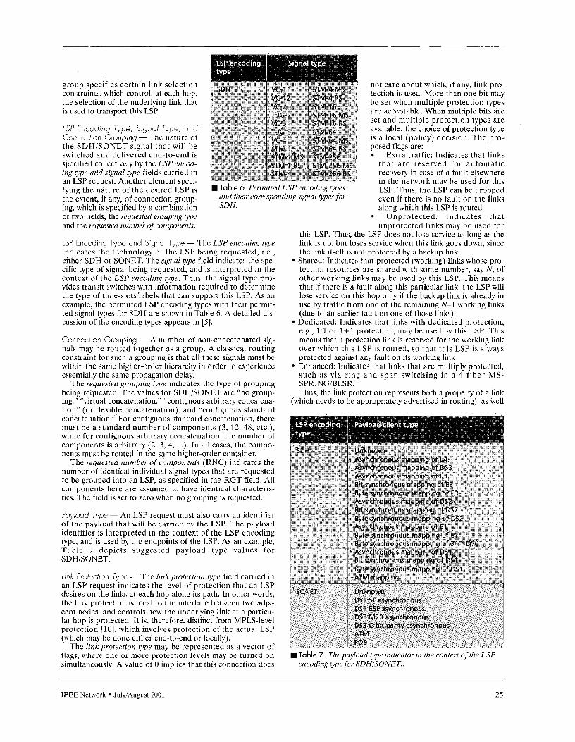
group specifies certain link selection not care about which, if any, link pro- constraints, which control, at each hop, tectiori is used. More than one bit may the selection of the underlying link that be set when multiple protection types is used to transport this LSP. are acccptable. When multiple bits i re
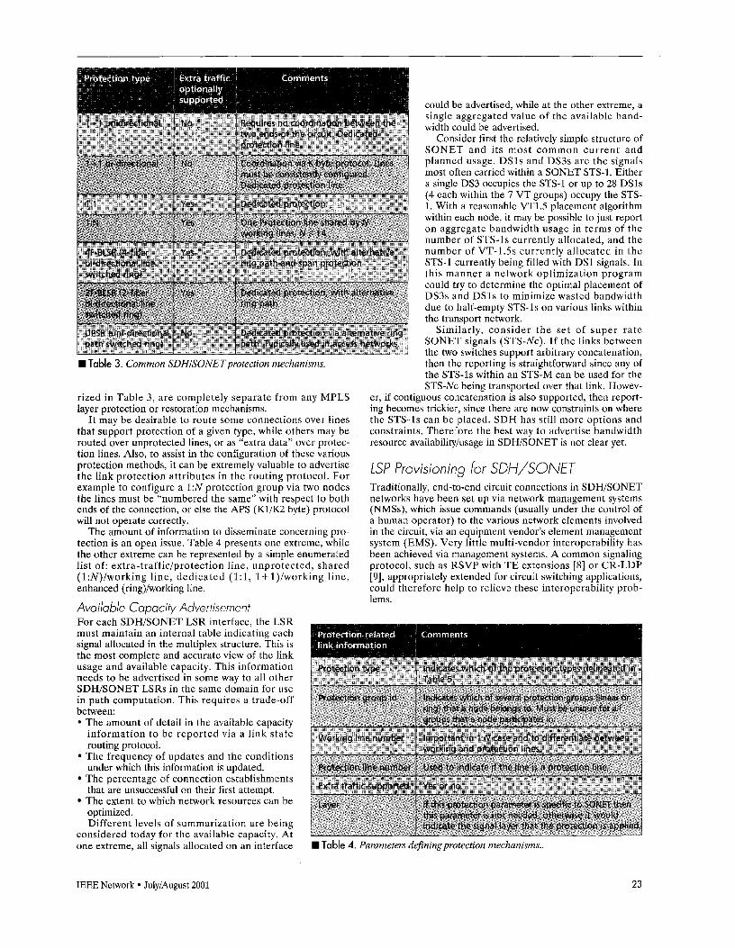
set and multiple protection types are LSP Encoding Type, Signa/ Type, and available, the choice of protection type Connection Grouping - The naturc of is a local (policy) decision. The pro- the SDHiSONET signal that will be posed flags are: switched and delivcrcd end-to-end is Extra traffic: Indicates that links spccified collectively by the LSP encod- that a rc reserved for automatic ing type and signal type fields carried in recovery in case of a fault elsewhere an LSP request. Another elemcnt speci- in the network may be used for this fying the nature of the desired LSP is LSP. Thus, the LSP can be dropped the extent, if any, of connection group- even if there is no fault on the links ing, which is specified by a combination along which this LSP is routed. of two fields, the requested grouping type Unprotected: Indicates that and the requested number of components. unprotectcd links may be used for
this LSP. Thus, the LSP does not lose scrvice as long as the LSP Encoding Type and Signal Type - The LSP encoding type link is up, but loses service when this link goes doan, since indicates the technology of the LSP being requested, i.e., the link itself is not protected by a backup link. either SDH or SONET. The signal type field indicate5 the spe- Shared: Indicates that protected (working) links whose pro- cific type of signal being requested, and is interpreted in the tection resources are shared with some number, say N , of context of thc LSP encoding type. Thus, the signal type pro- othcr working links may bc used by this LSP. This means vides tramit switches with information required to determine that if there is a fault along this particular link, the LSP will the type of time-alots/labels that can support this LSP. As an lose service on this hop only if the backup link is already in examplc, the permitted LSP encoding types with their permit- use by traffic from onc of the remaining N-1 working links ted signal types for SDH are shown in Table 6. A detailed dis- (due to an earlier fault on one of those links). cussion of the encoding types appears in [5]. Dcdicatcd. Indicates that links with dedicated protection,
e.g., 1:l or 1+1 protection, may be used by this LSP. This Connection Grouping - A number of non-concatenated sig- means that a protection link is rcscrved for the working link nals may be routed together as a group. A classical routing over which this LSP is routed, so that this LSP is always constraint for such a grouping is that all these signals must be protccted agaimt any fault on its working link within the samc higher-order hierarchy in order to experience Enhanced: Indicates that links that are multiply protected, essentially the same propagation delay. 5uch a\ via ring and span switching in a 4-fiber M S -
The requested grouping type indicates the type of grouping SPRINGIBLSR. being requested. The values for SDH/SONET are “no group- Thus, the link protection represents both a property of a link ing,” “virtual concatenation,’’ “contiguous arbitrary concatena- (which needs to be appropriately advertised in routing), as well tion” (or flexible concatenation), and “coiitiguous standard concatenation.” For contiguous standard concatenation, there must be a standard number of components (3, 12, 48, ctc.), while for contiguous arbitrary concatenation, the number of components is arbitrary (2, 3, 4, ...). In all cascs, the compo- ncnts must be routed in the Same higher-order container.
The requeyted number of components (RNC) indicates the number of identical individual signal types that are requested to be grouped into an LSP, as specified in the RGT tield. All components here are assumed to have identical characteris- tics. The ficld is set to zero when no grouping is requested.
Payioad Type - An LSP request must also carry an identifier of the payload that will be carried by the LSP. The payload identifier is interpreted in the context of the LSP encoding type, and is used by the endpoints of the LSP. As an examplc, Table 7 dcpicts suggested payload typc values for SDHISONET.
Link Protection Type - The hnk protection type field carried in an LSP request indicates the level of protection that an LSP desires on the links at each hop along its path. In other words, thc link protection is local to the interface bctween two adja- cent nodes, and controls how the underlying link at a paiticu- lar hop is protected. It is, therefore, distinct from MPLS-level protection [ lo] , which involves protection of thc actual LSP (which may be done either end-to-end or locally).
The link protection type may bc represented as a vector of flags, where one or more protection levels may be turned on simultaneously. A value of 0 implies that this connection does
Table 6.
sDH.
LSp encoding types their Lorre\Ponding AWal for
Table 7. Thepayload type indicator in the cuntext of the LSP encodrng lype Jor SDHISONET..
IEEE Network JulyiAugust 2001 25
COMPUTING, COMMUNICATIONS AND NETWORKING DIVISION DIRECTOR Los Alamos National Laboratory is seeking outstanding applicants for Director of the Computing, Communications and Networking (CCN) Division. Los Alamos is at the foretront of high performance computing and networking The CCN Division Director is responsible tor the acquisition/development, implementation, operation and support of all of Los Alamos’ high-performance computing environments, including present and future tera-scale systems. These include the present 1 teraOps Nirvana Blue system, the 3 teraOps Blue Mountain system, the planned 30 teraOps “9” computer system scheduled for delivery in April, 2002, and even higher-performance systems beyond these. “ Q wil l he the world’s largest and most capable platform. CCN is also responsible for the hardware and software aspects of the advanced visualization, archival storage, and advanced networking systems that are at the cutting edge of high performance computing. The CCN Division mission is to provide the world’s most powerful production high-performance computing environment for application to some of the most complex problems facing the nation The scope of the Division is complete from the machine room to the user desktop The CCN Division consists of approximately 470 scientists, engineers, systems operation staff, students and administrators and has an annual budget of approximately $1 50 million dollars.
Los Alamos National Laboratory is a key national resource for the development and integration of leading-edge science and technology to solve problems of national and global importance. High-performance computing i s central to the Laboratory’s core mission of ensuring safety and confidence in the U S. nuclear weapons stockpile. In addition, high-performance computing is an essential tool for the Laboratory to apply its scientific and engineering capabilities to assist the nation in addressing energy, environmental, infrastructure, and biological issues Partnering with universities and industries is critical to these missions and the CCN Division has many alliances and partnerships with major universities and industries across the US and abroad.
Los Alamos National Laboratory, located in the stunning Jemez mountains of northern New Mexico, offers the opportunity to work at a world-class research facility while enjoying a truly unique living environmerit. Long known for i ts artistic community, northern New Mexico also boasts a variety of exciting outdoor recreational opportunities, including hiking in the adjacent mountains and canyons, proximity to the Rocky Mountains and exceptional skiing opportunities at many nearby locations.
Salary and benetits are commensurate with experience The position requires the ability to obtain a DOE Q clearance, which normally requires L.S. citizenship, arld participation in the laboratory’s PSAP program Additional information about the position, the CCN Division, Los Alamos National Laboratory and the northern New Mexico and southwestern Colorado environments are
le at http://www.lanl.gov/ccnsearch. Further tion can also be obtained by contacting Ms. Mary
5-665-9921 or by email at [email protected].
a resume and cover letter, 3” to: Resume Service Center, 1663, Los Alamos, NM 87545.
as a constraint on which links may be used for a given path (which i s signaled during connection setup as specified above).
Conclusions In this article we presented a detailed account of the issues involved in applying MPLS-based coiltrol to TDM networks by focusing on the two main areas of application of these methods to TDM networks, namely, routing and signaling. As the industry moves toward this mode of operation, however, several issues require further consideration. One such area is routing protocol scalability, which requires a careful trade-off between the granularity of information advertised in routing and the volume of routing traffic generated. Similarly, thc number of underlying layers whose information is compressed into a single instance of the routing protocol is also an open question, and depends on the type of network model (overlay or peer) that a service provider intends to deploy. Finally, the bandwidth requirements of the control channel and the imple- mentation of the control channel itself are important issues that impact the realization of the distributed automated net- work control as proposed in this article.
References [ l ] G.707-2000, Network Node Interfoce for the Synchronous Digital Hierarchy
[2] ANSI T1 ,105-1995, “Synchronous Optical Network (SONET) - Basic
[3] G. Bernstein, J. Yotes, ond D. Saha, “IP-Centric Control and Management of
[4] L. Berger et a/., “Geneialized MPLS - Signoling Functional Description,”
151 E. Mannie et al., “GMPLS Extensions for SONET and SDH Contrj,” Iniernet
[6] B. Dovie, Y. Rekhter, ond M. Koufman, MPlS Technology ond Applications,
[7] J. Manchester, P. Bonenfant, and C. Newton, ”The Evolution of Transport
[a] L. Berger et al., “Generalized MPLS Signaling - RSVP-TE Extensions,” Inter-
[9] L. Berger et 01.. ”Generalized MPLS Si noling CR-LDP Extensions,” Internet
[ l O]V. Sharma and F. Heistrand, eds., ”Framework far MPLS-based Recovery,”
(SDH), International Telecommunication Union.
Description Including Multiplex Structure, Rates and Formats.”
Optical Transport Networks,” I € € € Commun. Mag., Oct. 2000.
Internet Draft: <draft-ietf-mpIs-generalized-signating-04.t~~, May 001
Draft: <draft-ietf-ccamp-gmpls-sonet-sdh-OO.txb, May 2001 ,
San Mateo, California, Jan. 2000.
Network Swvivability,!’ E€€ Commun . Mag., Aug. 1999.
net Draft:cdrah-ietf-mpls-generalized-rsvp-te-03.t~~, May 2001
Draft: cdroft-.ietf-mpls- enerolized-cr-l~p-03.txt>, May 2001 .
Internet Draft: <draFt-ietf-mpls-recovery-Frmwrk-02.txb, Mar. 2001 .
6 iograph ies GREG BERNSTEIN ([email protected]) is senior scientist ot Ciena Corporation spe- cializing in o tical network control and monogement planes. He was senior director for sofware engineering development at tightero Networks (acquired by Ciena Corporotion] where he led the development of intelli ent o tical switches. He was with Northern Telecom from 1994,until the founing ortightera Net- works in early 1998. At Northern Telecom, he was a senior manager responsi- bte For new roduct development in the oreos of ATM and Internet Protocol. He has filed or leen granted seven US/European patents in the areas of acketized voice, congestion control, and optical networking. Dr. Bernstein earneBhis Ph.D., M.S., and B.S. in electrical engineering and computer science from the University of California ot Berkeley
ERIC MANNIE i s technolo y and standards strategy manager ot Ebone IGTS), where he i s reyT ib !e er investigating and anolyzing new technologies. His current scope o activities is concerned with the integration of IP and optical tech- nologies. In that context he is a co-author of several GMPLS drahs and editor of
S) he worked as an IP telephon consul pany. Before that he worked for eighi of Brussels [ULB) where he was olso a
urers, operotors, and national and Euro- ties were focused on IP technologies, IP encing and IP telephony, cable modems,
and network management.
VlSHAL SHARMA ([email protected]) is principal consultoni at Metonoia, Inc., where he specializes in technical consulting for telecommunications vendors and sewice providers. His focus is on system/network architecture, algorithm and pro- tocol desi n, and system analysis. He earned a B. Tech. degree from the Indian Institute oPTechnology, Konpur, and M.S. and Ph.D. degrees from the Universiv of California, Santa Barbora. He has worked and consulted at companies such as Motorola, Tellabs, Jasmine Networks, ACT Networks, and Digital Instruments.
26 IEEE Network JulyiAugust 2001