Embed Size (px)
Citation preview

1
FREE VIBRATION ANALYSIS OF EDGE CRACKED FUNCTIONALLY GRADED
BEAMS RESTING ON WINKLER-PASTERNAK FOUNDATION
Şeref Doğuşcan Akbaş
Assoc. Prof. Dr., E-mail: [email protected]
Department of Civil Engineering, Bursa Technical University, Bursa, Turkey
Abstract
In this study, free vibration analysis of an edge cracked functionally graded cantilever beam resting on Winkler-
Pasternak foundation. Material properties of the beam change in the thickness direction according to exponential
distributions. The differential equations of motion are obtained by using Hamilton’s principle. The considered problem is investigated within the Euler-Bernoulli beam theory by using finite element method. The cracked beam is modeled as an
assembly of two sub-beams connected through a massless elastic rotational spring. In the study, the effects of the location
of crack, the depth of the crack, foundation stiffness and various material distributions on the natural frequencies and the
mode shapes of the cracked functionally graded beams are investigated in detail.
Keywords: Free vibration, Winkler-Pasternak Foundation, Open edge crack, Functionally graded materials,
1. Introduction
Structural elements are subjected to destructive effects in the form of initial defects within the
material or caused by fatigue or stress concentration. As a result of destructive effects, cracks occur
in the structural elements. It is known that a crack in structure elements introduces a local flexibility,
becomes more flexible and its dynamic and static behaviors will be changed. Cracks cause local
flexibility and changes in structural stiffness. Therefore, understanding the mechanical behavior and
the safe performance of edge-cracked structures is importance in designs.
Functionally graded materials (FGMs) are a new generation of composites where the volume fraction
of the FGM constituents vary gradually, giving a non-uniform microstructure with continuously
graded macro properties such as elasticity modulus, density, heat conductivity, etc.. Typically, in a
FGM, one face of a structural component is ceramic that can resist severe thermal loading and the
other face is metal which has excellent structural strength. FGMs consisting of heat-resisting ceramic
and fracture-resisting metal can improve the properties of thermal barrier systems because cracking
and delamination, which are often observed in conventional layered composites, are reduced by
proper smooth transition of material properties. Since the concept of FGMs has been introduced in
1980s, these new kinds of materials have been employed in many engineering application fields,
such as aircrafts, space vehicles, defense industries, electronics and biomedical sectors, to eliminate
stress concentrations, to relax residual stresses, and to enhance bonding strength. Because of the wide
material variations and applications of FGMs, it is important to study the responses of FGM
International Journal of Engineering & Applied Sciences (IJEAS)
Vol.7, Issue 3(2015)1-15

Akbaş
2
structures to mechanical and other loadings. With the increased use of FGMs, understanding the
mechanical behavior and safe performance of cracked FGM structures is very important.
In the literature, the free vibration and dynamic behavior of homogeneous cracked beams have been
extensively studied [1-17]. In recent years, the dynamic behavior of cracked FGM beams has been a
topic of active research. Sridhar et al. [18] developed an effective pseudo-spectral finite element
method for wave propagation analysis in anisotropic and inhomogeneous structures with or without
vertical and horizontal cracks. Briman and Byrd [19] studied the effect of damage on free and forced
vibrations of a functionally graded cantilever beam. Yang et al. [20] investigated an analytical study
on the free and forced vibration of inhomogeneous Euler–Bernoulli beams containing open edge
cracks that the beam is subjected to an axial compressive force and a concentrated transverse load
moving along the longitudinal direction. Yang and Chen [21] investigated free vibration and
buckling analysis of FGM beams with edge cracks by using Bernoulli–Euler beam theory and the
rotational spring model. Free vibration and elastic buckling of beams made of FGM containing open
edge cracks are studied within Timoshenko beam theory by Ke et al. [22]. Yu and Chu [23] studied
the transverse vibration characteristics of a cracked FGM beam by using the p-version of finite
element method. Ke et al. [24] investigated the post-buckling analysis of FGM beams with an open
edge crack based on Timoshenko beam theory and von Kármán nonlinear kinematics by using Ritz
method. Ferezqi et al. [25] studied an analytical investigation of the free vibrations of a cracked
Timoshenko beam made up of FGM. Yan et al. [26] studied dynamic response of FGM beams with
an open edge crack resting on an elastic foundation subjected to a transverse load moving at a
constant speed. Akbaş [27] investigated static analysis of an edge cracked FGM beam resting on
Winkler foundation by using finite element method. Yan et al. [28] investigated the nonlinear
flexural dynamic behavior of a clamped Timoshenko beam made of FGM with an open edge crack
under an axial parametric excitation which is a combination of a static compressive force and a
harmonic excitation force based on Timoshenko beam theory and von Kármán nonlinear kinematics.
Wei et al. [29] studied the free vibration of cracked FGM beams with axial loading, rotary inertia and
shear deformation by using an analytical method. Akbaş [30,31] studied geometrically nonlinear and
post-buckling analysis of edge cracked FG Timoshenko beams. Akbaş [32,33] investigated free
vibration and wave propagation of edge cracked FG beams.
In this study is the effect of the parameter of Winkler-Pasternak foundation on natural frequencies
and cracks in detail. To obtain more realistic answers and understand to edge cracked FGM beam,
more the parameter of FGM property distribution must be used in numerical results. Hence, a lot of
the parameters of FGM property distribution are used in this study.
The differential equations of motion are obtained by using Hamilton’s principle. The considered
problem is investigated within the Euler-Bernoulli beam theory by using finite element method. The
cracked beam is modeled as an assembly of two sub-beams connected through a massless elastic
rotational spring. Material properties of the beam change in the thickness direction according to
exponential distributions. In the study, the effects of the location of crack, the depth of the crack,
foundation stiffness and various material distributions on the natural frequencies and the mode
shapes of the functionally graded beams are investigated in detail.
2. Theory and Formulations
Consider a cantilever FGM beam of length L, width b, thickness h, containing an edge crack
of depth a located at a distance 1L from the left end, resting on Winkler-Pasternak foundation
with spring constants wk and pk , as shown in Figure 1. It is assumed that the crack is

Akbaş
3
perpendicular to beam surface and always remains open. When the Pasternak foundation
spring constant pk 0 , the foundation model reduces to Winkler type.
Figure 1: A cantilever FGM beam with an open edge crack resting on Winkler-Pasternak foundation
and cross-section.
In this study, Young’s modulus ( )YE and mass density ( )Y vary continuously in the
thickness direction (Y axis) according to exponential distributions as follows;
0
( )YE Y E e ,
0( )
YY e (1)
where 0E and 0 are the Young’s modulus and mass density at the midplane (Y=0) of the
beam. is a constant characterizing the gradual variation of the material properties along
thickness direction. When 0 , the material of the beam is homogeneous. According to Eq.
(1) that when / 2Y h , BE E and B ( BE and B are the Young’s modulus and
mass density of the bottom). When / 2Y h , TE E and T ( TE and T are the
Young’s modulus and mass density of the top).
According to the coordinate system (X,Y,Z) shown in figure 1, based on Euler-Bernoulli
beam theory, the axial and the transverse displacement field are expressed as
0
0
( , )-( , , ) ( , )
v X tu u Y
XX Y t X t (2)
0( , , ) ( , )v vX Y t X t (3)
Where 0u and 0v are the axial and the transverse displacements in the mid-plane, t indicates
time. Using Eq. (2) and (3), the linear strain- displacement relation can be obtained:
2
0 0
2
( , ) ( , )xx
u X t v X tuY
X X X (4)
According to Hooke’s law, constitutive equations of the FGM beam are as follows:
2
0 0
2
( , ) ( , )( ) ( )
xx xx
u X t v X tY
X XE EY Y (5)
Akbaş
4
Where xx and xx are normal stresses and normal strains in the X direction, respectively.
Based on Euler-Bernoulli beam theory, the elastic strain energy (V) and kinetic energy (T) of
the FGM beam resting on Winkler-Pasternak foundation are expressed as
2
2
0 0 0
1 1 1 ( , )( ( , )) dX dX
2 2 2
L L L
xx xx w p
A
v X tV dAdX k v X t k
x (6)
2 2
0 A
1
2
Lu v
T Y dAdXt t
(7)
With applying Hamilton’s principle, the differential equations of motion are obtained as
follows:
2 2 2 2
0 0 0 01 22 2 2 2XX XX
u v u vA B I I
X X X t t X (8)
2 2 22 2 2
0 0 0 0 00 3 12 2 2 2 2 2XX XX w p
u v v v vB D k v k I I
X X X X X t X t (9)
The stiffness components are defined as
2( , , ) (1, , )( )
A
XX XX XXB Y YE Y dAA D (10)
2
1 2 3( , , ) (1, , )
A
I Y YY dAI I (11)
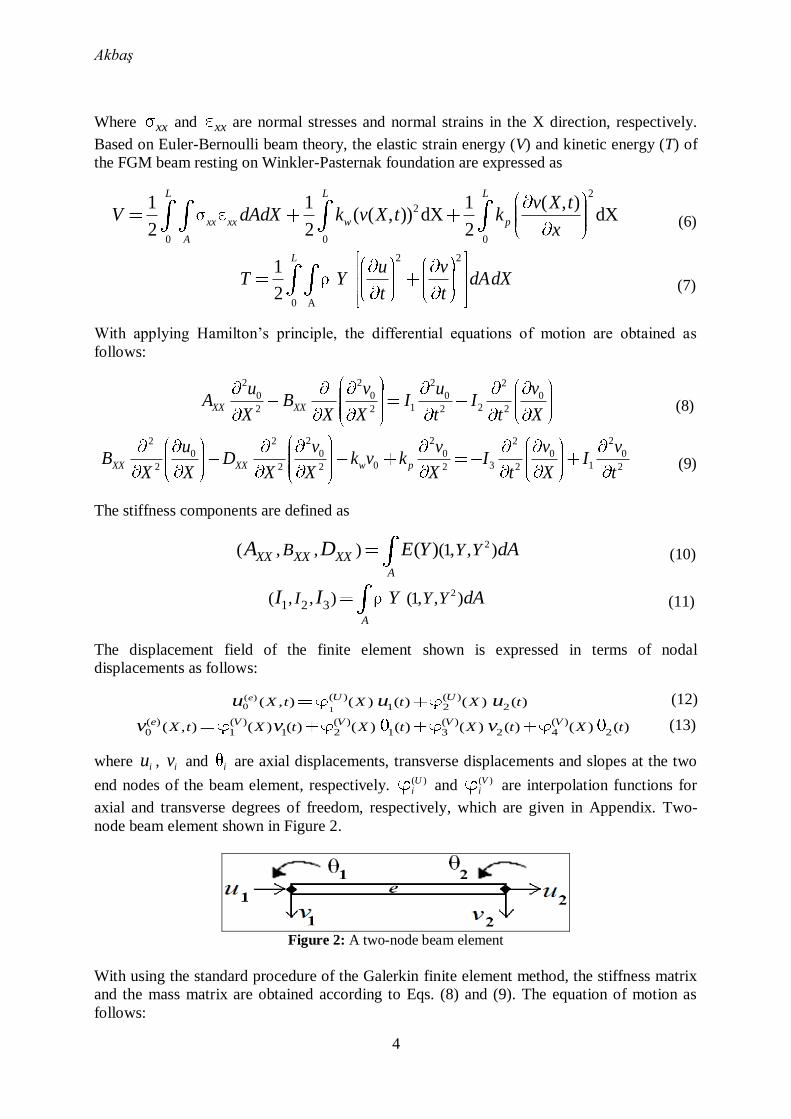
The displacement field of the finite element shown is expressed in terms of nodal
displacements as follows:
1
( )0
( ) ( )1 2 2( , ) ( ) ( ) ( ) ( )e U U
X t X t X tu u u (12)
( ) ( ) ( ) ( ) ( )0 1 1 2 1 3 2 4 2( , ) ( ) ( ) ( ) ( ) ( ) ( ) ( ) ( )e V V V V
X t X t X t X t X tv v v (13)
where iu , iv and i are axial displacements, transverse displacements and slopes at the two
end nodes of the beam element, respectively. ( )Ui and ( )V
i are interpolation functions for
axial and transverse degrees of freedom, respectively, which are given in Appendix. Two-
node beam element shown in Figure 2.
Figure 2: A two-node beam element
With using the standard procedure of the Galerkin finite element method, the stiffness matrix
and the mass matrix are obtained according to Eqs. (8) and (9). The equation of motion as
follows:

Akbaş
5
{ } { } 0q qK M (14)
where K is the stiffness matrix and [M] is the mass matrix. { }q is nodal displacement vector
which as follows
{ } { , , }Tq u v (15)
The stiffness matrix K can be expressed as a sum of three submatrices as shown below:
w pb
K K K K (16)
Where ( )b
K , ( )w
K and ( )pK are beam stiffness matrix, Winkler foundation stiffness
matrix and Pasternak foundation stiffness matrix, respectively. Explicit forms of [K] are given
in Appendix. The mass matrix M can be expressed as a sum of four sub-matrices as shown
below:
U V UM M M M M (17)
Where UM , VM and M are the contribution of u, v and degree of freedom to the
mass matrix, UM is coupling mass matrix due to coupling between u and . Explicit forms
of M are given in Appendix.
The cracked beam is modeled as an assembly of two sub-beams connected through a massless
elastic rotational spring shown in figure 3.
Figure 3. Rotational spring model.
The bending stiffness of the cracked section Tk is related to the flexibility G by
1T
kG
(18)
Cracked section’s flexibility G can be derived from Broek’s approximation [34]:
2 2 21 dG
2 da
( )
( )
IK M
E a (19)
where M is the bending moment at the cracked section, IK is the stress intensity factor (SIF)
under mode I bending load and is a function of the geometry, the loading, and the material
properties as well. indicates Poisson’s ratio which is taken to be constant since its
influence on the stress intensity factors is quite limited [35]. For an FGM strip with an open
edge crack under bending, the analytical solution and the expression of SIF is given Yu And
Chu [23] that obtained from the data given by Erdogan and Wu [35] through Lagrange
interpolation technique:

Akbaş
6
2
6( , / )
I R
MK a F
bhE a h (20)
Where a is depth of crack, RE is the ratio of Young’s modulus of bottom and top surfaces of
the beam ( /B TE E ) and F is an unknown function of two independent variables. The
function F is can be expressed as follows [23];
2 3 2
2 2 3
1 2 3 4 5 6
7 8 9 10 11
ln [ln ] [ln ] / /
1 ln [ln ] / / /
( ) ( ) ( ) ( ) ( )( , / )
( ) ( ) ( ) ( ) ( )
R R R
R R
R
p p E p E p E p a h p a hF
p E p E p a h p a h p a hE a h (21)
Where the coefficients 1p , 2p , …, 10p , 11p =1.1732, -0.3539, 0.0289, -0.0061, 0.6625, 3.072,
-0.0014, -0.0017, 1.9917, -0.3496, -3.0982 are given in Yu And Chu [23] that are determined
by fitting Eq. (20) based on the least square method to the numerical values of the SIF for
specific material gradients and normalized crack size given by Erdogan and Wu [35].
The spring connects the adjacent left and right elements and couples the slopes of the two
FGM beam elements at the crack location. In the massless spring model, the compatibility
conditions enforce the continuities of the axial displacement, transverse deflection, axial force
and bending moment across the crack at the cracked section ( 1X L ), that is,
1 2u u , 1 2
v v , 1 2N N , 1 2
M M (22)
The discontinuity in the slope is as follows:
1 2
1 2 1( )T T
k kdv dv
MdX dX
(23)
Based on the massless spring model, the stiffness matrix of the cracked section as follows:
1/ 1/
[ ]1/ 1/
T T
T T
Cr
k k
k k
G GK
G G (24)
The stiffness matrix of the cracked section is written according to the displacement vector:
1 2( ){ } { , }T
Crq (25)
Where 1 and 2 are the angles of the cracked section. With adding crack model, the
equations of motion for the finite element and by use of usual assemblage procedure the
following system of equations of motion for the whole system can be obtained as follows:
( )
( ){ } { } 0Cr
q qK K M (26)
If the global nodal displacement vector { }q is assumed to be harmonic in time with circular
frequency , i.e { } { } i tq q e becomes, after imposing the appropriate end conditions, an
eigenvalue problem of the form:
2
( )( ){ } 0
CrqK K M (27)

Akbaş
7
Where { }q is a vector of displacement amplitudes of the vibration. The dimensionless
quantities can be expressed as
2
0
10
L
DI
, 4
0
ww
L
D
kk , 2
0
pp
L
D
kk , X
X
L,
Y
hY , B
R
T
EE
E , BR
T
(28)
Where is the dimensionless frequency, wk is the dimensionless Winkler parameter, pk is
the dimensionless Pasternak parameter, RE is the ratio of Young’s modulus of bottom and top
surfaces of the beam, R is the ratio of mass density of bottom and top surfaces of the beam.
0D and
10I indicate the value of XXD and 1I of an isotropic homogeneous beam.
3. Numerical Results
In the numerical examples, the natural frequencies and the mode shapes of the beams are
calculated and presented in figures for various the effects of the location of crack, the depth of
the crack, foundation stiffness and material distributions. The beam considered in numerical
examples is made of Aluminum ( 70 ,E GPa 0.33, 32780 /kg m ) which the material
constants change exponentially as in Eq. (1). The top surface of the FGM beam is Aluminum.
In the numerical integrations, five-point Gauss integration rule is used. Unless otherwise
stated, it is assumed that the width of the beam is 0.1b m , height of the beam is 0.1h m
and length of the beam is 30L h in the numerical results. In the numerical calculations, the
number of finite elements is taken as n = 100.
In figure 4, the effect of the dimensionless Winkler parameter wk on the dimensionless
fundamental frequency 1 of edge cracked FGM beams ( 2RE , / 0.6a h , 0pk ) are
shown for various the crack location 1 /L L .
Figure 4: The effect the dimensionless Winkler parameter wk on the dimensionless fundamental
frequency 1 for various the crack location 1 /L L .
It is seen from figure 4 that the increasing the value of the dimensionless Winkler parameter
wk play important role on the fundamental frequency. With increase in the dimensionless
Winkler parameter wk , the fundamental frequency increases. Because, with increasing the
Winkler parameter wk , the beam gets more stiffer. Also, it is observed figure 4 that the

Akbaş
8
differences between of the crack location 1 /L L decrease with increase the Winkler parameter
wk .
Figure 5 shows that the effect of the dimensionless Winkler parameter wk on the
dimensionless fundamental frequency 1 of edge cracked FGM beams ( 2RE ,
1 / 0.05L L , 0pk ) are shown for various the crack depth ratio /a h .
Figure 5: The effect the dimensionless Winkler parameter
wk on the dimensionless fundamental
frequency 1 for various the crack depth ratio /a h .
It is seen from figure 5 that with the increasing the value of the dimensionless Winkler
parameter wk , the differences between of the crack depth ratio /a h decrease. Increases with
the stiffness parameter of the foundation, the effects of the crack reduce.
In Figure 6, the effect of the the dimensionless Winkler parameter wk on the dimensionless
fundamental frequency 1 of edge cracked FGM beams ( / 0.6a h , 1 / 0.05L L , 0pk )
are shown for 2RE and 0.5RE .
Figure 6: The effect the dimensionless Winkler parameter wk on the dimensionless fundamental
frequency 1 for 2RE and 0.5RE .

Akbaş
9
It is seen from figure 6 that with increase in the value of the dimensionless Winkler parameter
wk , the difference between the dimensionless fundamental frequency of 2RE and
0.5RE decreases. It is shown results that the stiffness parameter of the foundation is very
effective for reducing disadvantage of cracks.
Figure 7 displays the effect of the dimensionless Winkler parameter wk on the first and
second normalized vibration mode shapes for 2RE , 1 / 0.05L L , / 0.6a h , 0pk .
Figure 7: The effect the dimensionless Winkler parameter wk on the a) first and b) second
normalized vibration mode shapes.
It is seen from figure 7 that with increase in the value of dimensionless Winkler parameter
wk , vibration mode shapes change significantly. It is observed from the results, the stiffness
parameter of the foundation is very effective for the mechanical behavior of the beam. It is
observed from figure 7 that the dimensionless Winkler parameter wk is more effective in
first vibration mode than second vibration mode.
In figure 8, the effect of the dimensionless Pasternak parameter pk on the dimensionless
fundamental frequency 1 of edge cracked FGM beams ( 2RE , / 0.6a h , 10wk ) are
shown for various the crack location 1 /L L .
Figure 8: The effect the dimensionless Pasternak parameter
pk on the dimensionless fundamental
frequency 1 for various the crack location 1 /L L .

Akbaş
10
It is seen from figure 8 that with increase in the dimensionless Pasternak parameter pk , the
fundamental frequency increases. Because, with increasing the Pasternak parameter pk , the
beam gets more stiffer. The effect of Pasternak parameter pk on the dimensionless
fundamental frequency is less than Winkler parameter wk for various the crack location
1 /L L .
Figure 9 shows that the effect of the dimensionless Pasternak parameter pk on the
dimensionless fundamental frequency 1 of edge cracked FGM beams ( 2RE ,
1 / 0.05L L , 10wk ) are shown for various the crack depth ratio /a h . In figure 10, the
effect of the the dimensionless Pasternak parameter pk on the dimensionless fundamental
frequency 1 of edge cracked FGM beams ( / 0.6a h , 1 / 0.05L L , 10wk ) are shown
for 2RE and 0.5RE .
Figure 9: The effect the dimensionless Pasternak parameter
pk on the dimensionless fundamental
frequency 1 for various the crack depth ratio /a h .
Figure 10: The effect the dimensionless Pasternak parameter
pk on the dimensionless fundamental
frequency 1 for 2RE and 0.5RE .
It is seen from figure 9 and figure 10 that the stiffness parameter of the Pasternak foundation
is not effective for reducing disadvantage of cracks, significantly.

Akbaş
11
Figure 11 displays the effect of the dimensionless Pasternak parameter pk on the first and
second normalized vibration mode shapes for 2RE , 1 / 0.05L L , / 0.6a h , 10wk .
Figure 11: The effect the dimensionless Pasternak parameter
pk on the a) first and b) second
normalized vibration mode shapes.
It is seen from figure 11 that with increase in the value of dimensionless Pasternak parameter
pk , vibration mode shapes change significantly. It is observed from figure 11 that the
dimensionless Pasternak parameter pk is more effective in second vibration mode than first
vibration mode.
4. Conclusions
Free vibration analysis of an edge cracked FGM cantilever beam resting on Winkler-
Pasternak foundation are investigated within the Euler-Bernoulli beam theory by using finite
element method. Material properties of the beam change in the thickness direction according
to an exponential function. The differential equations of motion are obtained by using
Hamilton’s principle. The cracked beam is modeled as an assembly of two sub-beams
connected through a massless elastic rotational spring. The influences of the location of crack,
the depth of the crack, foundation stiffness and various material distributions on the natural
frequencies and the mode shapes of the FGM beams are examined in detail.
The following conclusions are reached from the obtained results:
(1) The crack locations and the crack depth have a great influence on the vibration
characteristics of the FGM beam.
(2) The stiffness parameter of Winkler foundation is very effective for reducing disadvantage
of cracks.
(3) The stiffness parameter of the Pasternak foundation is not effective for reducing
disadvantage of cracks.
(4) The stiffness parameters of the foundation have a great influence on vibration mode
shapes.
Appendix

Akbaş
12
The interpolation functions for axial degrees of freedom are
( ) ( ) ( )
1 2( ) ( ) ( )T
U U UX X X , (A1)
where
( )
1 ( ) 1U
e
XX
L, (A2)
( )
2 ( )U
e
XX
L, (A3)
The interpolation functions for transverse degrees of freedom are
( ) ( ) ( ) ( ) ( )
1 2 3 4( ) ( ) ( ) ( ) ( )T
V V V V VX X X X X , (A4)
where
( )
1
2 3
2 3( )
3 21V
ee
XX X
L L, (A5)
( )
2
2 3
3( )
2V
e e
XX X
L LX , (A6)
( )
3
2 3
32( )
3 2V
e e
XX X
LL, (A7)
( )
4
2 3
3( )V
e e
XX X
L L, (A8)
where eL indicates the length of the finite beam element. The components of the stiffness
matrix K : the beam stiffness matrix b
K , Winkler foundation stiffness matrix wK and
Pasternak foundation stiffness matrix pK are as follows
( ) ( )
( ) ( )
b T
A Bb b
B Db b
K K
K KK
, (A9)
where
( ) ( )
( )
0
e U U
b
TL
XXA A
d dK dX
dX dX, (A10)
( ) ( )
( )
0
2
2
e V U
b
TL
XXB B
d dK dX
dXdX (A11)
( ) ( )
( )
0
2 2
2 2
e V V
b
TL
XXD D
d dK dX
dX dX, (A12)

Akbaş
13
( ) ( )
0
e
V V
LT
w wk dXK , (A13)
( ) ( )
0
e V VTL
p pkd d
dXdX dX
K , (A14)
The components of the mass matrix M : UM , VM , M and UM are as follows
( ) ( )1
0
eLT
U UU I dXM (A15)
( ) ( )1
0
eLT
V V
V I dXM (A16)
( ) ( )
3
0
eTL V Vd d
IdX dX
dXM (A17)
2
0
( ) ( )( ) ( )
eTL V VT
U UU I
d ddX
dX dXM (A18)
References
[1] Dimarogonas, A.D., Vibration of Cracked Structures: A State of the Art Review.
Engineering Fracture Mechanics, 55, 831–857, 1996.
[2] Yokoyama, T. and Chen, M.C., Vibration Analysis of Edge-Cracked Beams using a Line-
Spring Model. Engineering Fracture Mechanics,59, 403–409,1998.
[3] Kisa, M., Brandon, J. and Topcu, M. Free Vibration Analysis of Cracked Beams by a
Combination of Finite Elements and Component Mode Synthesis Methods. Computers
and Structures, 67, 215–223, 1998.
[4] Chondros, T.G., Dimarogonas, A.D. and Yao, J., A continuous cracked beam vibration
Theory. Journal of Sound and Vibration, 215, 17–34, 1998.
[5] Kısa, M. and Brandon, J.A. “Free vibration analysis of multiple openedge cracked beams
by component mode synthesis,” Structural Engineering Mechanics,10, 81-92, 2000.
[6] Lin, H.P., Chang, S.C. and Wu, J.D., Beam vibrations with an arbitrary number of
Cracks. Journal of Sound and Vibration, 258, 987–999, 2002.
[7] Nag, A., Roy Mahapatra, D., Gopalakrishnan, S. and Sankar, T.S., A Spectral Finite
Element with Embedded Delamination for Modeling of Wave Scattering in Composite
Beams. Composites Science and Technology, 63, 2187–2200, 2003.
[8] Zheng, D.Y. and Kessissoglou, N.J., Free vibration analysis of a cracked beam by finite
element method. Journal of Sound and Vibration, 273, 457–475, 2004.
[9] Kısa, M., Free Vibration analysis of a cantilever composite beam with multiple cracks.
Composites Science and Technology, 64, 1391-1402, 2004.
[10] El Bikri, K., Benamar, R. and Bennouna, M.M.,Geometrically Non-Linear Free
Vibrations of Clamped-Clamped Beams with an Edge Crack. Computers & Structures,
84, 485–502, 2006.
[11] Kısa, M. and Gürel, M.A., Free vibration analysis of uniform and stepped cracked beams
with circular cross sections. International Journal of Engineering Science, 45, 364–380,
2007.
[12] Aydin, K., Vibratory characteristics of Euler-Bernoulli beams with an arbitrary number
of cracks subjected to axial load. Journal of Vibration and Control, 14, 485-510, 2008.

Akbaş
14
[13] Shafiei, M. and Khaji, N., Analytical solutions for free and forced vibrations of a
multiple cracked Timoshenko beam subject to a concentrated moving load. Acta
Mechanica, 221, 79–97, 2011.
[14] Akbaş, Ş.D., Free vibration characteristics of edge cracked piles with circular cross
section. International Journal of Engineering Research and Applications, 3, 363-371,
2013.
[15] Akbaş, Ş.D., Wave propagation analysis of edge cracked beams resting on elastic
foundation. International Journal of Engineering and Applied Sciences, 6,40- 52, 2014.
[16] Akbaş, Ş.D., Wave Propagation Analysis of Edge Cracked Circular Beams under Impact
Force. PLos One, 9(6), 100496, 2014.
[17] Akbaş, Ş.D., Large Deflection Analysis of Edge Cracked Simple Supported Beams.
Structural Engineering and Mechanics, 54, 433-451, 2015.
[18] Sridhar, R., Chakraborty, A. and Gopalakrishnan, S., Wave Propagation Analysis in
Anisotropic and Inhomogeneous Uncracked and Cracked Structures using Pseudospectral
Finite Element Method. International Journal of Solids and Structures, 43, 4997–5031,
2006.
[19] Briman, V. and Byrd, L.W., Vibration of Damaged Cantilevered Beams Manufactured
from Functionally Graded Materials. AIAA Journal., 45, 2747–2757, 2007.
[20] Yang, J., Chen, Y., Xiang, Y. and Jia, X.L., Free and Forced Vibration of Cracked
Inhomogeneous Beams under an Axial Force and a Moving Load,” Journal of Sound and
Vibration, 312, 166–181, 2008.
[21] Yang, J. and Chen, Y., Free Vibration and Buckling Analyses of Functionally Graded
Beams with Edge Cracks. Composite Structures, 83, 48–60, 2008.
[22] Ke, L. L., Yang, J., Kitipornchai, S. and Xiang,Y., Flexural Vibration and Elastic
Buckling of a Cracked Timoshenko Beam Made of Functionally Graded Materials.
Mechanics of Advanced Materials and Structures,16, 488–502, 2009.
[23] Yu, Z. and Chu, F., Identification of crack in functionally graded material beams using
the p- version of finite element method, Journal of Sound and Vibration, 325, 69–84,
2009.
[24] Ke, L. L., Yang, J. and Kitipornchai, S., Postbuckling analysis of edge cracked
functionally graded Timoshenko beams under end shortening. Composite Structures, 90,
152–160, 2009.
[25] Ferezqi, H.Z., Tahani, M. and Toussi, H.E., Analytical approach to free vibrations of
cracked Timoshenko beams made of functionally graded materials. Mechanics of
Advanced Materials and Structures,17, 353–65, 2010.
[26] Yan, T., Kitipornchai, S., Yang, J. and He, X. Q., Dynamic behaviour of edge-cracked
shear deformable functionally graded beams on an elastic foundation under a moving
load. Composite Structures, 93, 2992–3001, 2011.
[27] Akbaş, Ş.D., Static analysis of a functionally graded beam with edge cracks on elastic
foundation, Proceedings of the 9 th International Fracture Conference, Istanbul, Turkey,
2011.
[28] Yan, T., Yang, J. and Kitipornchai, S., Nonlinear dynamic response of an edge-cracked
functionally graded Timoshenko beam under parametric excitation. Nonlinear Dynamics,
67, 527–540, 2012.
[29] Wei, D., Liu, Y. and Xiang, Z., An analytical method for free vibration analysis of
functionally graded beams with edge cracks. Journal of Sound and Vibration, 331, 1686–
1700, 2012.
[30] Akbaş, Ş.D., Geometrically Nonlinear Static Analysis of Edge Cracked Timoshenko
Beams Composed of Functionally Graded Material. Mathematical Problems in
Engineering, 2013, Article ID 871815, 14 pages, 2013.

Akbaş
15
[31] Akbaş, Ş.D., Free vibration characteristics of edge cracked functionally graded beams by
using finite element method. International Journal of Engineering Trends and
Technology, 4, 4590-4597, 2013.
[32] Akbaş, Ş.D. Wave Propagation in Edge Cracked Functionally Graded Beams Under
Impact Force. Journal of Vibration and Control, 1-15, Doi: 10.1177/1077546314547531,
2014.
[33] Akbaş, Ş.D., On Post-Buckling Behavior of Edge Cracked Functionally Graded Beams
Under Axial Loads. International Journal of Structural Stability and Dynamics, 15,
1450065, 2015.
[34] D. Broek, Elementary engineering fracture mechanics, Martinus Nijhoff Publishers,
Dordrecht, 1986.
[35] F. Erdogan and B.H. Wu, “The Surface Crack Problem for a Plate with Functionally
Graded Properties,” Journal of Applied Mechanics, vol. 64, no. 3, pp. 448–456, 1997.